

Page 1

Cisco VG310 and Cisco VG320 Voice Gateways Hardware Installation
Guide
First Published: July 25, 2014
Americas Headquarters
Cisco Systems, Inc.
170 West Tasman Drive
San Jose, CA 95134-1706
USA
http://www.cisco.com
Tel: 408 526-4000
800 553-NETS (6387)
Fax: 408 527-0883
Text Part Number: OL-31292-01
Page 2

©
2014 Cisco Systems, Inc. All rights reserved.
Page 3

CONTENTS
Preface
CHAPTER 1
Preface ix
Related Documentation ix
Obtaining Documentation x
Conventions x
Obtaining Technical Assistance xi
Submitting a Service Request xi
Definitions of Service Request Severity xii
Obtaining Additional Publications and Information xii
Overview of the Cisco VG310 and Cisco VG320 Voice Gateways 1
Introduction to Cisco VG310 and Cisco VG320 Analog Voice Gateways 1
Front Panel View 2
Back Panel View 2
Locating the Product Serial Number 3
Interfaces and Service Capabilities of Cisco VG310 and Cisco VG320 3
Physical Description and LEDs 4
Gigabit Ethernet Ports and LED Indicators 7
Port Numbering Conventions 8
Hardware Features 8
Real-Time Clock 8
Built-In Interface Ports 8
USB Serial Console Port 9
Removable and Interchangeable Modules and Cards 9
Supported Voice Interface Cards and Voice WAN Interface Cards 10
Periodic Inspection and Cleaning 10
Software Elements 10
Configuration Connections 10
OL-31292-01 iii
Cisco VG310 and Cisco VG320 Voice Gateways Hardware Installation Guide
Page 4

Contents
Configuration Methods 11
CHAPTER 2
Planning Your Installation 13
Safety Recommendations 13
General Safety Practices 13
Safety Tips 14
Preventing Electrostatic Discharge Damage 14
Temperature Control and Ventilation 15
Enclosed Racks 15
Wall-Mounted 15
Bench-Mounted 15
Access to Chassis 16
Rack Requirements 16
Chassis Grounding 16
Power Source 16
Cable Types 16
Distance Limitations for Interface Cables 17
Console Port and Auxiliary Port Considerations 17
CHAPTER 3
Console Port Connections 17
Auxiliary Port Connections 18
Interference Considerations 19
Mounting Tools and Equipment 19
Keeping Track–Checklist 20
Installation Checklist 20
Site Log 21
Installing the Cisco VG310 and Cisco VG320 Voice Gateways 23
Safety Recommendations 23
Maintaining Safety with Electricity 24
General Safety Practices 25
Safety Tips 26
Preventing Electrostatic Discharge Damage 26
What You Need to Know 27
Before You Begin 27
Unpacking and Inspecting 27
Cisco VG310 and Cisco VG320 Voice Gateways Hardware Installation Guide
iv OL-31292-01
Page 5

Contents
Mounting the Chassis 27
Mounting Screws 28
Mounting the Chassis on a Rack 28
Mounting the Chassis on a Wall 30
Installing the Voice Gateway on a Bench 33
Installing the Ground Connection 33
Connecting Cables 34
LAN and Power Cables 35
Connecting Power 36
Connecting the Chassis to an AC Power Source 37
Connecting a UPS to an AC-Powered Voice Gateway 38
Connecting the Chassis to a +12V DC Power Supply 38
Connecting to a Console Terminal or Modem 41
Connecting to a Serial Port with Microsoft Windows 42
Connecting an Auxiliary Port to a Modem 42
Connecting a Gigabit Ethernet Port to a Gigabit Ethernet Switch 43
Ports and Cabling 43
Cable-Connection Procedures and Precautions 44
Voice Cables 45
Connecting the Analog Voice Interface to a Distribution Panel 46
Ports, Connectors, and Pinouts 47
Remote Terminal Connections (If Applicable) 48
Connecting to a Modem 48
Connecting to a Remote PC 48
Connecting to a Remote ASCII Terminal 49
Removing and Installing a CompactFlash Memory Card 49
Removing a CompactFlash Memory Card 49
Replacing a CompactFlash Memory Card 50
CHAPTER 4
Configuring the Cisco VG310 and Cisco VG320 Voice Gateways 53
Getting Your Network Information 53
Checklist for Power Up 53
Power-On Procedure 54
Performing the Initial Configuration on the Voice Gateway 55
Using the setup Command Facility 55
OL-31292-01 v
Cisco VG310 and Cisco VG320 Voice Gateways Hardware Installation Guide
Page 6

Contents
Using Cisco Configuration Professional Express 58
Using Cisco IOS CLI—Manual Configuration 58
Troubleshooting Cisco VG310 and Cisco VG320 59
CHAPTER 5
APPENDIX A
APPENDIX B
Getting Software Licenses for Cisco VG310 and Cisco VG320 Voice Gateways 61
Activating a New Software Package or Feature 61
RMA License Transfer 62
Technical Specifications 63
Physical Specifications 63
Power Specifications 64
Ports 64
Environmental Specifications 65
Acoustic 65
Transportation and Storage 65
Regulatory Compliance 66
Cable Specifications and Information 69
Console and Auxiliary Port Signals and Pinouts 69
Console Port Signals and Pinouts 70
Auxiliary Port Signals and Pinouts 71
Identifying a Rollover Cable 72
Console Port to ASCII Terminal 72
Gigabit Ethernet Connector Pinouts (RJ-45) 73
ISDN BRI Interface 74
ISDN BRI Connections 74
ISDN BRI Pinouts 75
E&M Pinouts 76
Analog Voice RJ-21 Pinouts 77
Serial Connection Signals and Pinouts 79
Connecting the WIC to the Network 79
EIA/TIA-232 Connections 79
EIA/TIA-449 Connections 80
V.35 Connections 80
X.21 Connections 81
Cisco VG310 and Cisco VG320 Voice Gateways Hardware Installation Guide
vi OL-31292-01
Page 7

Contents
EIA/TIA-530 Connections 81
USB Type A-to-USB 5-Pin Mini Type B Cable 82
OL-31292-01 vii
Cisco VG310 and Cisco VG320 Voice Gateways Hardware Installation Guide
Page 8

Contents
Cisco VG310 and Cisco VG320 Voice Gateways Hardware Installation Guide
viii OL-31292-01
Page 9

Preface
This preface discusses the audience, organization, and conventions of this publication and describes how to
obtain additional documentation.
Related Documentation, page ix
•
Obtaining Documentation, page x
•
Conventions, page x
•
Obtaining Technical Assistance, page xi
•
Obtaining Additional Publications and Information, page xii
•
Related Documentation
The Cisco IOS software running your Cisco Voice Gateway includes extensive features and functionality.
For information that is beyond the scope of this document, or for additional information, use the resources
listed here:
Cisco VG310 and Cisco VG320 Voice Gateways Regulatory Compliance and Safety
•
Information—Provides essential safety information applicable to your Cisco VG310 or Cisco VG320
and contains multiple-language translations of the safety warnings applicable to the device.
• Cisco VG310 and Cisco VG320 Voice Gateways Software Configuration Guide—Provides detailed
configuration information about the Cisco VG310 and Cisco VG320 voice gateways.
• Release Notes—Provides up-to-date information about Cisco IOS software releases used in Cisco VG310
and Cisco VG320 voice gateways.
Installing and Replacing Field Replaceable Units in Cisco VG310 and Cisco VG320 Voice
•
Gateways—This document is intended for trained and qualified service personnel. This document
describes how to install field-replaceable units (FRUs) in the Cisco VG310 and Cisco VG320 voice
gateways.
OL-31292-01 ix
Cisco VG310 and Cisco VG320 Voice Gateways Hardware Installation Guide
Page 10

Obtaining Documentation
Obtaining Documentation
Cisco documentation is available on Cisco.com. Cisco also provides several ways to obtain technical assistance
and other technical resources. These sections explain how to obtain technical information from Cisco Systems.
Cisco.com
You can access the most current Cisco documentation at:
http://www.cisco.com/cisco/web/psa/default.html?mode=prod
You can access the Cisco website at:
http://www.cisco.com/
You can access international Cisco websites at:
http://www.cisco.com/web/siteassets/locator/index.html
Ordering Documentation
Registered Cisco.com users (Cisco direct customers) can order Cisco product documentation from the Ordering
tool:
Preface
http://www.cisco.com/web/ordering/root/index.html
Non-registered Cisco.com users can order documentation through a local account representative by calling
Cisco Systems Corporate Headquarters (California, USA) at 408 526-7208 or, elsewhere in North America,
by calling 800 553-NETS (6387).
Conventions
This document use the following conventions: Cisco
Note
Caution
Means reader take note. Notes contain helpful suggestions or references to materials that may not be
contained in this manual.
Means reader be careful. In this situation, you might do something that could result in equipment damage
or loss of data.
Safety Warnings
Safety warnings appear throughout this publication in procedures that, if performed incorrectly, might harm
you. A warning symbol precedes each warning statement. The safety warnings provide safety guidelines that
you should follow when working with any equipment that connects to electrical power or telephone wiring.
Warnings are translated into several languages. For information about compliance guidelines and translated
safety warnings, refer to the Regulatory Compliance and Safety Information document for the Cisco VG310
and Cisco VG320 Voice Gateways.
Cisco VG310 and Cisco VG320 Voice Gateways Hardware Installation Guide
x OL-31292-01
Page 11

Preface
Obtaining Technical Assistance
Warning
IMPORTANT SAFETY INSTRUCTIONS
This warning symbol means danger. You are in a situation that could cause bodily injury. Before you
work on any equipment, be aware of the hazards involved with electrical circuitry and be familiar with
standard practices for preventing accidents. Use the statement number provided at the end of each warning
to locate its translation in the translated safety warnings that accompanied this device. Statement 1071
SAVE THESE INSTRUCTIONS
Obtaining Technical Assistance
For all customers, partners, resellers, and distributors who hold valid Cisco service contracts, Cisco Technical
Support provides 24-hour-a-day, award-winning technical assistance. The Cisco Technical Support Website
on Cisco.com features extensive online support resources. In addition, Cisco Technical Assistance Center
(TAC) engineers provide telephone support. If you do not hold a valid Cisco service contract, contact your
reseller.
Cisco Technical Support Website
The Cisco Technical Support Website provides online documents and tools for troubleshooting and resolving
technical issues with Cisco products and technologies. The website is available 24 hours a day, 365 days a
year at this URL:
http://www.cisco.com/cisco/web/support/index.html
Access to all tools on the Cisco Technical Support Website requires a Cisco.com user ID and password. If
you have a valid service contract but do not have a user ID or password, you can register at:
https://tools.cisco.com/RPF/register/register.do
Submitting a Service Request
Using the online TAC Service Request Tool is the fastest way to open S3 and S4 service requests. (S3 and
S4 service requests are those in which your network is minimally impaired or for which you require product
information.) After you describe your situation, the TAC Service Request Tool automatically provides
recommended solutions. If your issue is not resolved using the recommended resources, your service request
will be assigned to a Cisco TAC engineer. The TAC Service Request Tool is located at:
https://tools.cisco.com/ServiceRequestTool/scm/mgmt/case
For S1 or S2 service requests or if you do not have Internet access, contact the Cisco TAC by telephone. (S1
or S2 service requests are those in which your production network is down or severely degraded.) Cisco TAC
engineers are assigned immediately to S1 and S2 service requests to help keep your business operations
running smoothly.
To open a service request by telephone, use one of the following numbers:
Asia-Pacific: +61 2 8446 7411 (Australia: 1 800 805 227)
EMEA: +32 2 704 55 55
USA: 1 800 553 2447
OL-31292-01 xi
Cisco VG310 and Cisco VG320 Voice Gateways Hardware Installation Guide
Page 12

Definitions of Service Request Severity
For a complete list of Cisco TAC contacts, go to:
http://www.cisco.com/c/en/us/support/web/tsd-cisco-worldwide-contacts.html.
Definitions of Service Request Severity
To ensure that all service requests are reported in a standard format, Cisco has established severity definitions.
• Severity 1 (S1)—Your network is “down,” or there is a critical impact to your business operations. You
and Cisco will commit all necessary resources around the clock to resolve the situation.
• Severity 2 (S2)—Operation of an existing network is severely degraded, or significant aspects of your
business operation are negatively affected by inadequate performance of Cisco products. You and Cisco
will commit full-time resources during normal business hours to resolve the situation.
• Severity 3 (S3)—Operational performance of your network is impaired, but most business operations
remain functional. You and Cisco will commit resources during normal business hours to restore service
to satisfactory levels.
• Severity 4 (S4)—You require information or assistance with Cisco product capabilities, installation, or
configuration. There is little or no effect on your business operations.
Preface
Obtaining Additional Publications and Information
Information about Cisco products, technologies, and network solutions is available from various online and
printed sources.
Cisco Marketplace provides a variety of Cisco books, reference guides, and logo merchandise. Visit
•
Cisco Marketplace, the company store, at: http://www.cisco.com/go/marketplace.
Cisco Press publishes a wide range of general networking, training and certification titles. Both new and
•
experienced users will benefit from these publications. For current Cisco Press titles and other information,
go to Cisco Press at: http://www.ciscopress.com/.
Packet magazine is the Cisco Systems technical user magazine for maximizing Internet and networking
•
investments. Each quarter, Packet delivers coverage of the latest industry trends, technology
breakthroughs, and Cisco products and solutions, as well as network deployment and troubleshooting
tips, configuration examples, customer case studies, certification and training information, and links to
scores of in-depth online resources. You can access Packet magazine at: http://www.cisco.com/packet.
Internet Protocol Journal is a quarterly journal published by Cisco Systems for engineering professionals
•
involved in designing, developing, and operating public and private internets and intranets. You can
access the Internet Protocol Journal at: http://www.cisco.com/ipj.
• World-class networking training is available from Cisco. You can view current offerings at: http://
www.cisco.com/web/learning/index.html.
Cisco VG310 and Cisco VG320 Voice Gateways Hardware Installation Guide
xii OL-31292-01
Page 13

CHAPTER 1
Overview of the Cisco VG310 and Cisco VG320
Voice Gateways
This chapter provides a brief description of the Cisco VG310 and Cisco VG320 voice gateways and contains
the following sections:
Introduction to Cisco VG310 and Cisco VG320 Analog Voice Gateways, page 1
•
Locating the Product Serial Number, page 3
•
Interfaces and Service Capabilities of Cisco VG310 and Cisco VG320 , page 3
•
Physical Description and LEDs, page 4
•
Gigabit Ethernet Ports and LED Indicators, page 7
•
Port Numbering Conventions, page 8
•
Hardware Features, page 8
•
Periodic Inspection and Cleaning, page 10
•
Software Elements, page 10
•
Introduction to Cisco VG310 and Cisco VG320 Analog Voice
Gateways
The Cisco VG310 and Cisco VG320 Analog Voice Gateways provide an intermediate path to enable the Time
Division Multiplex (TDM) to IP transition.
Cisco VG310 and Cisco VG320 support the following interfaces:
Gigabit Ethernet
•
USB
•
Enhanced High-Speed WAN Interface Card (EHWIC), Voice Interface Card (VIC), and Voice WAN
•
Interface Card (VWIC)
OL-31292-01 1
Cisco VG310 and Cisco VG320 Voice Gateways Hardware Installation Guide
Page 14
Front Panel View
This unit is intended for installation in restricted access areas. A restricted access area can be accessed only
through the use of a special tool, lock and key, or other means by security. Statement 1017
The Cisco VG310 and Cisco VG320 chassis support the following:
•
•
•
• (For Cisco VG310 only)—24-analog Foreign Exchange Station (FXS) voice ports using one RJ-21
• (For Cisco VG320 only)—48-analog FXS voice ports using two RJ-21 analog voice interface connectors
Front Panel View
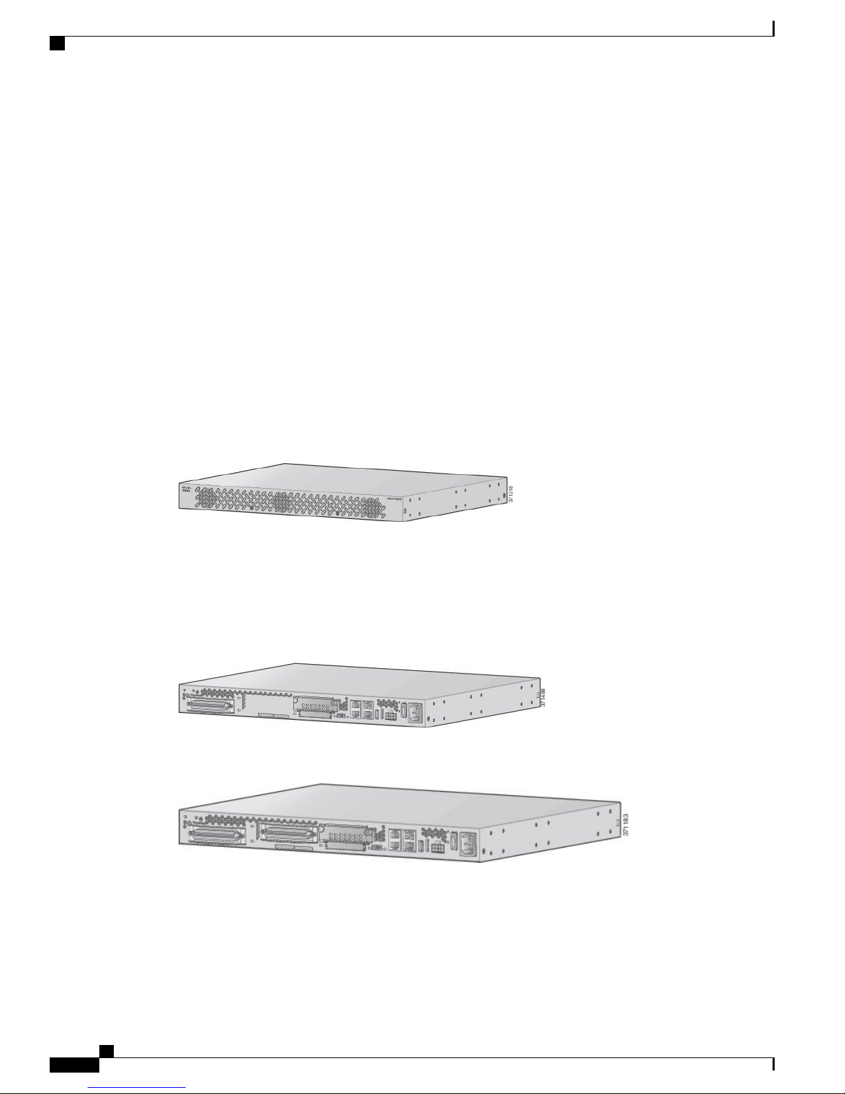
The following figure shows the front panel of the Cisco VG310 and Cisco VG320 chassis.
Overview of the Cisco VG310 and Cisco VG320 Voice Gateways
Two 10/100/1000BASE-T Gigabit Ethernet ports
External compact flash memory
AC and DC power inputs
analog voice interface connector
Figure 1: Front Panel of the Cisco VG310 and Cisco VG320 Chassis
Back Panel View
The following figures show the back panel views of the Cisco VG310 and Cisco VG320 chassis respectively.
Figure 2: Back Panel of the Cisco VG310 Chassis
Figure 3: Back Panel of the Cisco VG320 Chassis
Cisco VG310 and Cisco VG320 Voice Gateways Hardware Installation Guide
2 OL-31292-01
Page 15
Overview of the Cisco VG310 and Cisco VG320 Voice Gateways
Locating the Product Serial Number
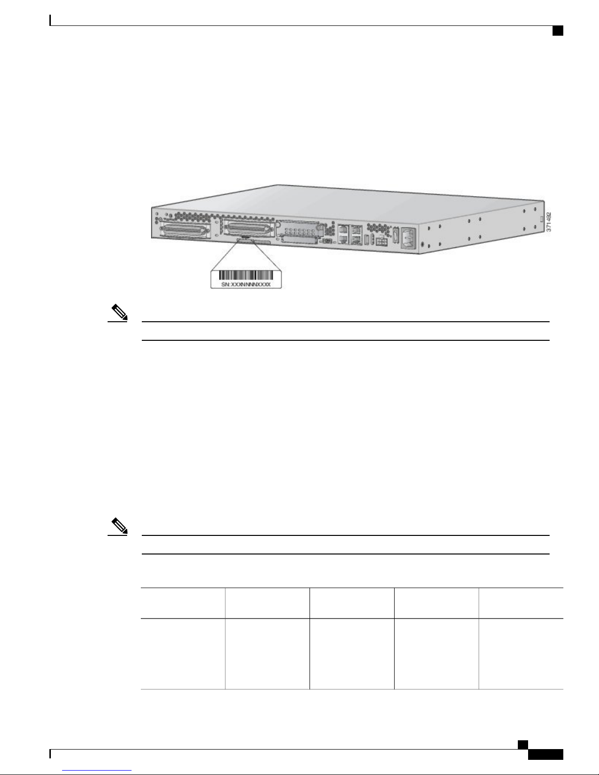
The serial number label for the Cisco VG310 and Cisco VG320 Analog Voice Gateways is located on the
back panel of the chassis, as shown in the following figure.
Figure 4: Locating the Product Serial Number
Locating the Product Serial Number
The serial number for Cisco VG310 and Cisco VG320 is 11 characters long.Note
Interfaces and Service Capabilities of Cisco VG310 and Cisco
VG320
The following table describes the physical ports and the services supported by each port type:
• Two administrative ports—One console and one auxiliary
Two 10/100BASE-T Gigabit Ethernet LAN ports
•
Cisco VG310 is equipped with an RJ-21 port for connection to a distribution panel
•
Cisco VG320 has two RJ-21 ports for connection to a distribution panel
•
WAN Interface is not supported on Cisco VG310 and Cisco VG320.Note
Table 1: Cisco VG310 and Cisco VG320 Analog Voice Gateway Interfaces and Service Capabilities
Port
Configuration
DetailsServices SupportedInterface ToInterface
Console
Port 0/0
OL-31292-01 3
EIA/TIA-232
asynchronous serial
(data
communications
equipment)
Cisco VG310 and Cisco VG320 Voice Gateways Hardware Installation Guide
ASCII terminal
Personal computer
Local administrative
access
RJ-45 physical
interface
Page 16

Physical Description and LEDs
Overview of the Cisco VG310 and Cisco VG320 Voice Gateways
Port
Auxiliary
Port 0/1
Gigabit Ethernet
Port 0/0, 0/1
(For Cisco VG310
only)
RJ-21
24 analog FXS
voice ports
Port 0/0/0 to 0/0/23
(For Cisco VG320
only)
RJ-21
48 analog FXS
voice ports
Port 0/0/0 to 0/0/23
and port 0/1/0 to
0/1/23
Configuration
asynchronous serial
(data terminal
equipment)
(802.3)
FXS (loop start or
ground-start)
FXS (loop start or
ground-start)
ModemEIA/TIA-232
Analog phone, fax,
or modem
Network side of key
system
Network side of
analog PBX
Analog phone, fax,
or modem
Network side of key
system
Network side of
analog PBX
Remote
administrative
access
Data backup
DataLAN1000BASE-T
Analog voice/fax or
modem
Analog voice/fax or
modem
DetailsServices SupportedInterface ToInterface
RJ-45 physical
interface
RJ-45 physical
interface
RJ-21 physical
interface
RJ-21 physical
interface
Compact slot
memory slot 0
Compact slot
memory slot 0
Physical Description and LEDs
All interface ports, connectors, and LEDs are on the back panel of the chassis.
——
Flash card
Cisco VG310 and Cisco VG320 Voice Gateways Hardware Installation Guide
4 OL-31292-01
Page 17
Overview of the Cisco VG310 and Cisco VG320 Voice Gateways
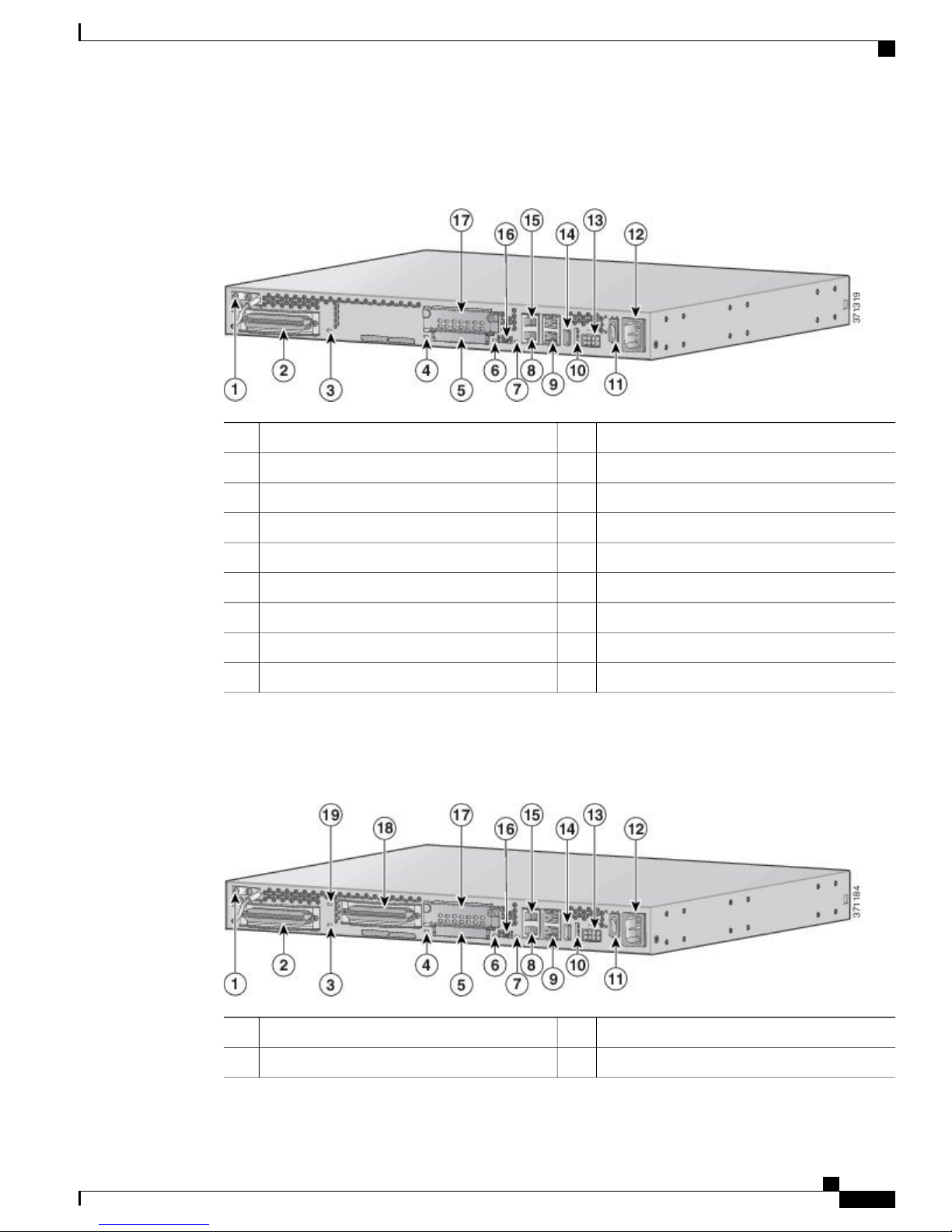
The following figure describes the back panel features of Cisco VG310.
Figure 5: Back Panel Features of Cisco VG310
Physical Description and LEDs
Status LEDs for DC input power10Chassis ground connection1
On/off switch11FXS RJ-21 connector2
AC power input12Status LED for FXS RJ-21 connector3
DC power input13Status LED for CompactFlash card4
USB connector14CompactFlash card slot5
RJ-45 serial AUX port15Status LED for mini USB6
Mini USB connector16Status LED for console7
EHWIC slot17RJ-45 serial console port8
Gigabit Ethernet ports (2)9
The following figure describes the back panel features of Cisco VG320.
Figure 6: Back Panel Features of Cisco VG320
OL-31292-01 5
On/off switch11Chassis ground connection1
AC power input12FXS RJ-21 connector 12
Cisco VG310 and Cisco VG320 Voice Gateways Hardware Installation Guide
Page 18

Physical Description and LEDs
Status LEDs for DC input power10
LED Indicators
The following table summarizes the LED indicators that are located on the chassis of both VG310 and VG320,
but not on the removable modules or interface cards.
For descriptions of LEDs in removable modules and interface cards, see the applicable documentation for
those products.
Overview of the Cisco VG310 and Cisco VG320 Voice Gateways
DC power input13Status LED for FXS RJ-21 connector 13
USB connector14Status LED for CompactFlash card4
RJ-45 serial AUX port15CompactFlash card slot5
Mini USB connector16Status LED for mini USB6
EHWIC slot17Status LED for console7
FXS RJ-21 connector 218RJ-45 serial console port8
Status LED for FXS RJ-21 connector 219Gigabit Ethernet ports (2)9
Table 2: Cisco VG310 and Cisco VG320 LED Indicators
Amber
GreenACT
DescriptionColorLED
Normal operation. System is receiving power.GreenSYS
Operating system boot up in progress.Blinking green
Power supply is available, but the unit has an error
condition.
System is not receiving power.Off
Indicates packet activity between the forwarding and
routing engine and an I/O port.
No packet transfers are occurring.Off
PVDM3 is detected and enabled.GreenPVDM
PVDM3 is detected, but has an error condition.Amber
PVDM3 is not installedOff
Cisco VG310 and Cisco VG320 Voice Gateways Hardware Installation Guide
6 OL-31292-01
Page 19

Overview of the Cisco VG310 and Cisco VG320 Voice Gateways
Gigabit Ethernet Ports and LED Indicators
DescriptionColorLED
GreenCF
Off
Green, blinkingSPD
GreenSER CON
GreenUSB CON
Flash memory is being accessed. Do not remove the
CompactFlash memory card.
CompactFlash error.Amber
Flash memory is not being accessed. Safe to remove the
CompactFlash memory card, if required.
System is running.GreenPWR
System is off.Off
Indicates that the Ethernet port has a link partner.GreenLNK
No link available.Off
Frequency of blinking indicates speed of the port.
For information about the LED blinking pattern, see
Gigabit Ethernet Ports and LED Indicators, on page 7.
No link available.Off
Indicates that the RJ-45 port is the active console port.
Note
When SER CON LED is On, the USB CON
LED will be Off.
Indicates that the USB port is the active console port.
Note
When USB CON LED is On, the SER CON
LED will be Off.
Gigabit Ethernet Ports and LED Indicators
There are two RJ-45 Gigabit Ethernet (GE) ports (GE0/0 and GE0/1) on the Cisco VG310 and Cisco VG320
chassis. These ports support 10BASE-T, 100BASE-TX, and 1000BASE-T standards.
The LED indicators for the GE ports display a sequence of blinks followed by a pause to indicate the link
speed. The following table describes the link speed indicated by the LED indicators of the GE ports.
Table 3: LED Indicator Pattern for GE Ports
OL-31292-01 7
Link SpeedLED Indicator Pattern
10 MbpsBlinks once followed by a pause
100 MbpsBlinks twice followed by a pause
1000 MbpsBlinks thrice followed by a pause
Cisco VG310 and Cisco VG320 Voice Gateways Hardware Installation Guide
Page 20

Port Numbering Conventions
Port Numbering Conventions
The following are the port numbering conventions for the Cisco VG310 chassis and Cisco VG320 chassis:
An external compact flash card is numbered CF 0.
•
10/100/1000BASE-T ports are numbered 10/100/1000BASE-T 0/0 (bottom) and 10/100/1000BASE-T
•
0/1 (top).
• (For Cisco VG310 chassis only)—FXS and E/M voice port numbering begins at 0/0/0 and extends to
0/0/23.
• (For Cisco VG320 chassis only)—FXS and E/M voice port numbering begins at 0/0/0 and extends to
0/0/23 for FXS RJ-21 connector 1. For FXS RJ-21 connector 2, port numbering begins at 0/1/0 and
extends to 0/1/23. To locate the FXS voice ports, see Physical Description and LEDs, on page 4.
Overview of the Cisco VG310 and Cisco VG320 Voice Gateways
Hardware Features
This section describes the hardware features of Cisco VG310 and Cisco VG320 and includes the following:
Real-Time Clock, on page 8
•
USB Serial Console Port, on page 9
•
Removable and Interchangeable Modules and Cards, on page 9
•
Real-Time Clock
When the system powers up, the internal real-time clock with battery backup provides the system software
with the time of day. This allows the system to verify the validity of the certification authority (CA) certificate.
Cisco VG310 and Cisco VG320 have a lithium battery. This battery lasts for the duration of the life time of
Cisco VG310 or Cisco VG320 under the operating environmental conditions specified for the chassis, and is
not field replaceable.
Note
If the lithium battery unit in Cisco VG310 and Cisco VG320 fails, the unit must be returned to Cisco for
repair.
Built-In Interface Ports
The following table summarizes the interface ports built into the chassis.
Cisco VG310 and Cisco VG320 Voice Gateways Hardware Installation Guide
8 OL-31292-01
Page 21

Overview of the Cisco VG310 and Cisco VG320 Voice Gateways
Table 4: Summary of Built-In Interfaces on Cisco VG310 and Cisco VG320
Built-In Interface Ports
Management PortsData Ports
USB Type A10/100/1000 GE
RJ-45
Console Serial,
RJ-45
USB Serial Console Port
The Mini-USB Type B serial port is enabled to perform management tasks on Cisco VG310 and Cisco VG320.
Before establishing physical connectivity between a personal computer and a voice gateway using this port,
make sure that a Windows USB device driver is installed.
Removable and Interchangeable Modules and Cards
The following table summarizes the type of removable modules and cards that can be installed in Cisco VG310
and Cisco VG320 to provide specific capabilities.
Table 5: Removable and Interchangeable Modules and Cards
DescriptionInternal or ExternalModules and
Cards
Auxiliary, RJ-45Console Serial,
Mini-USB (Type
B)
11112
Data Modules
(PVDM3)
memory
ExternalEHWIC
The EHWIC slot on the chassis supports one EHWIC card.
Legacy interface single-width cards such as WAN interface
cards (WICs), voice interface cards (VICs), and high-speed
WAN interface cards (HWICs) are supported in the EHWIC
slot.
For a list of supported VICs and VWICs, see Supported Voice
Interface Cards and Voice WAN Interface Cards.
InternalPacket Voice
The PVDM slot on the motherboard supports only a PVDM3.
Older PVDM cards are not supported.
ExternalFlash memory
A CompactFlash memory card stores the operating system
software image. The CompactFlash memory card can have sizes
of 512 MB, 1 GB, 2 GB, 4 GB, and 8 GB.
ExternalCisco USB flash
A Cisco USB flash memory (USB 2.0 compliant) supports 1
GB of memory.
Note
We recommend that you do not use third-party USB
devices on Cisco VG310 or Cisco VG320. USB 1.x
devices are also not supported on Cisco VG310 and
Cisco VG320.
OL-31292-01 9
Cisco VG310 and Cisco VG320 Voice Gateways Hardware Installation Guide
Page 22

Periodic Inspection and Cleaning
Cards
Overview of the Cisco VG310 and Cisco VG320 Voice Gateways
DescriptionInternal or ExternalModules and
ExternalDC power supply
(Optional)
Provides backup power using a 12-volt battery backup system
if AC power is not available.
Supported Voice Interface Cards and Voice WAN Interface Cards
The EHWIC slot on the Cisco VG310 and Cisco VG320 chassis supports the following VICs and VWICs:
Cisco VIC3-2FXS/DID
•
Cisco VIC3-2FXS-E/DID
•
Cisco VIC3-4FXS/DID
•
Cisco VIC3-2E/M
•
Cisco VIC2-2FXO
•
Cisco VIC2-4FXO
•
Cisco VWIC3-1MFT-T1/E1
•
Cisco VWIC3-2MFT-T1/E1
•
Cisco VIC2-2BRI-NT/TE
•
Periodic Inspection and Cleaning
Periodic inspection and cleaning of the external surface of the voice gateway is recommended to minimize
the negative impact of dust or debris. The frequency of inspection and cleaning is dependent upon the severity
of the environmental conditions, but a minimum of every six months is recommended. Cleaning involves
vacuuming the unit's air intake and exhaust vents.
Software Elements
The operating system for Cisco VG310 and Cisco VG320 is Cisco IOS software, which resides in the flash
memory.
Configuration Connections, on page 10
•
Configuration Methods, on page 11
•
Configuration Connections
You can use an ASCII terminal or a PC to configure a Cisco VG310 or Cisco VG320 Analog Voice Gateway.
The configuration can be performed in several ways:
Locally, with a direct connection through the console port
•
Cisco VG310 and Cisco VG320 Voice Gateways Hardware Installation Guide
10 OL-31292-01
Page 23

Overview of the Cisco VG310 and Cisco VG320 Voice Gateways
Remotely, with a connection through the auxiliary port and a modem
•
Through Telnet and TFTP
•
Configuration Methods
For information on performing the initial configuration on an analogy voice gateway, see Configuring the
Cisco VG310 and Cisco VG320 Voice Gateways, on page 53.
Configuration Methods
OL-31292-01 11
Cisco VG310 and Cisco VG320 Voice Gateways Hardware Installation Guide
Page 24

Configuration Methods
Overview of the Cisco VG310 and Cisco VG320 Voice Gateways
Cisco VG310 and Cisco VG320 Voice Gateways Hardware Installation Guide
12 OL-31292-01
Page 25

CHAPTER 2
Planning Your Installation
Before you install your Cisco VG310 or Cisco VG320 Analog Voice Gateway, read the information provided
in the following sections:
Safety Recommendations, page 13
•
Preventing Electrostatic Discharge Damage, page 14
•
Temperature Control and Ventilation, page 15
•
Access to Chassis, page 16
•
Rack Requirements, page 16
•
Chassis Grounding, page 16
•
Power Source, page 16
•
Cable Types, page 16
•
Distance Limitations for Interface Cables, page 17
•
Console Port and Auxiliary Port Considerations, page 17
•
Interference Considerations, page 19
•
Mounting Tools and Equipment, page 19
•
• Keeping Track–Checklist, page 20
Safety Recommendations
The following information is included to alert you about safety recommendations and best practices to be
followed when working with this equipment.
General Safety Practices
Follow these guidelines to ensure personal safety and protect the equipment:
Keep the area around the chassis clear of obstacles and free from dust during and after installation.
•
OL-31292-01 13
Cisco VG310 and Cisco VG320 Voice Gateways Hardware Installation Guide
Page 26

Safety Tips
Planning Your Installation
If you remove a chassis during installation and maintenance, place the chassis cover in a safe place.
•
Keep tools away from walk areas to prevent hazards such as slips, trips, and falls.
•
Do not wear loose clothing that may get caught in the chassis.
•
Wear safety glasses if you are working under conditions that might be hazardous to the eyes.
•
Warning
Safety Tips
This equipment must be installed and maintained by service personnel as defined by AS/NZS 3260.
Incorrectly connecting this equipment to a general-purpose outlet could be hazardous. The
telecommunications lines must be disconnected 1) before unplugging the main power connector or 2)
while the housing is open, or both. Statement 1043
Use these tips as safety guidelines when installing and working around this equipment:
Locate the emergency power off switch for the room in which you are working in order to be able to
•
quickly turn off power, if an electrical accident occurs.
Disconnect all power before installing or removing a chassis.
•
Do not work alone if potentially hazardous conditions exist.
•
Never assume that power is disconnected from a circuit. Always check.
•
Look carefully for possible hazards in your work area, such as moist floors, ungrounded power extension
•
cables, and missing safety grounds.
If an electrical accident occurs, proceed as follows:
•
Use caution; do not become a victim yourself.
◦
Turn off power to the system.
◦
If possible, send another person to get medical aid. Otherwise, assess the condition of the victim
◦
and then call for help.
Determine if the person needs rescue breathing or external cardiac compressions, and then take
◦
appropriate action.
Preventing Electrostatic Discharge Damage
Always follow ESD-prevention procedures when removing and replacing components. These procedures
include:
Ensure that the chassis is electrically connected to earth ground.
•
Wear an ESD-preventive wrist strap, ensuring that it makes good skin contact.
•
Connect a clip to the ESD-strap connection jack (to the left of the power switch on the rear of the chassis)
•
or to an unpainted chassis frame surface.
Cisco VG310 and Cisco VG320 Voice Gateways Hardware Installation Guide
14 OL-31292-01
Page 27

Planning Your Installation
Temperature Control and Ventilation
Caution
For safety, periodically check the resistance value of the antistatic strap, which should be between 1 МΩ
and 10 МΩ.
Temperature Control and Ventilation
The installation location (room, closet, or cabinet) for Cisco VG310 and Cisco VG320 should always be well
ventilated and provide adequate air circulation to ensure proper cooling. The room temperature should be
between 32 °F and 104 °F (0 °C to 40 °C).
The Cisco VG310 and Cisco VG320 analog voice gateway chassis is designed for back-to-front airflow.Note
Enclosed Racks
Note
Enclosed racks must have adequate ventilation. An enclosed rack should never be overcrowded and should
have louvers and a fan.
If the Cisco VG310 or Cisco VG320 analog voice gateway is installed in an enclosed rack with a ventilation
fan at the top, make sure that heated air drawn upward from other equipment does not prevent adequate
cooling.
If the chassis is installed using slide rails, check for blocked ventilation ports when it is in position in the rack
or cabinet. Make sure that the ventilation ports of the unit are not blocked.
Note
Baffles can help isolate exhaust air from intake air. Baffles also help draw cooling air through the cabinet.
The best location for baffles depends on the airflow patterns in the rack. You can test the airflow by
experimenting with different equipment arrangements.
Wall-Mounted
If Cisco VG310 or Cisco VG320 is installed on a wall, there should be plenty of space on both sides to ensure
that there is adequate airflow through the chassis.
Bench-Mounted
If the unit is placed on a bench top, do not stack other equipment or paper on the chassis. Provide plenty of
space for air circulation (front to back). Inadequate ventilation can result in overheating and damage.
OL-31292-01 15
Cisco VG310 and Cisco VG320 Voice Gateways Hardware Installation Guide
Page 28

Access to Chassis
Access to Chassis
Allow space at the rear of the chassis for cable connections. Also consider the need to access the chassis for
future upgrades, maintenance, and troubleshooting.
Rack Requirements
Use the following information to plan your equipment-rack configuration:
Allow clearance around the rack for maintenance.
•
Enclosed racks must have adequate ventilation. Ensure that the rack is not congested, because each voice
•
gateway generates heat. An enclosed rack should have louvered sides and a fan to provide cooling air.
Heat generated by equipment near the bottom of the rack can be drawn upward into the intake ports of
the equipment above it.
When mounting a chassis in an open rack, ensure that the rack frame does not block the ports. If the
•
chassis is installed on slides, check the position of the chassis when it is seated in the rack.
Planning Your Installation
Chassis Grounding
Chassis grounding is provided through the power cable, which uses a standard grounding plug. However, the
chassis also requires a reliable earth ground using the earth ground lug and hardware provided. For more
information, see Installing the Ground Connection, on page 33.
Power Source
You can connect Cisco VG310 or Cisco VG320 to either an AC power source or a +12V DC power supply.
Caution
The chassis provides inputs for both AC and DC power. Design your installation to use only one type of
power. Do not use AC and DC power at the same time. If you do, the unit stops operating, and you must
reboot it with only a single power source.
For more information, see Connecting Power, on page 36.
Cable Types
The cable types are dependent on the Cisco VG310 or Cisco VG320 analog voice gateway that you are using.
For more information, see Interfaces and Service Capabilities of Cisco VG310 and Cisco VG320 , on page
3 and Cable Specifications and Information, on page 69.
Cisco VG310 and Cisco VG320 Voice Gateways Hardware Installation Guide
16 OL-31292-01
Page 29

Planning Your Installation
Distance Limitations for Interface Cables
Distance Limitations for Interface Cables
When planning your installation, consider distance limitations and potential electromagnetic interference
(EMI) as defined by the Electronic Industries Association (EIA). Distance-limitation information is included
for the following Voice Gateway ports:
• Gigabit Ethernet ports—The maximum segment distance for Gigabit Ethernet is 330 feet (100 meters)
(specified in IEEE 802.3).
• FXS analog voice ports—The maximum distance is established by a total allowable loop resistance,
including the phone or terminal equipment, of 600 Ohms.
Console Port and Auxiliary Port Considerations
Cisco VG310 and Cisco VG320 include an asynchronous serial console port and an auxiliary port. The console
and auxiliary ports provide access to the unit either locally using a console terminal connected to the console
port, or remotely, using a modem connected to the auxiliary port. This section discusses important cabling
information to consider before connecting the unit to a console terminal or modem.
The main difference between the console and auxiliary ports is that the auxiliary port supports hardware flow
control and the console port does not. Flow control paces the transmission of data between a sending device
and a receiving device. Flow control ensures that the receiving device can absorb the data sent to it before the
sending device sends more. When the buffers on the receiving device are full, a message is sent to the sending
device to suspend transmission until the data in the buffers has been processed. Because the auxiliary port
supports flow control, it is ideally suited for use with the high-speed transmissions of a modem. Console
terminals send data at speeds slower than modems do; therefore, the console port is ideally suited for use with
console terminals.
Console Port Connections
Cisco VG310 and Cisco VG320 have EIA/TIA-232 asynchronous (RJ-45) and USB 5-pin mini Type B,
2.0-compliant serial console ports. The console port do not have any hardware flow control. Shielded USB
cables with properly terminated shields are recommended.
EIA/TIA-232
Depending on the cable and the adapter used, this port appears as a Date Terminal Equipment (DTE) or Data
Circuit-Terminating Equipment (DCE) device at the end of the cable. Only one port can be used at the same
time.
The default parameters for the console port are 9600 baud, 8 data bits, 1 stop bit, and no parity. The console
port does not support hardware flow control.
USB Serial Console
Use the USB console port on the chassis to access the Cisco IOS CLI and perform configuration tasks. A
terminal emulation program, such as Microsoft HyperTerminal for Windows, is required to establish
communication between the voice gateway and a PC. The USB serial console port connects directly to the
USB connector of a PC using a 5-pin mini USB Type A or USB Type-B cable. The USB console supports
full-speed (12 Mbps) operation.
OL-31292-01 17
Cisco VG310 and Cisco VG320 Voice Gateways Hardware Installation Guide
Page 30

Auxiliary Port Connections
Always use shielded USB cables with a properly terminated shield.Note
The default parameters for the console port are 9600 baud, 8 data bits, no parity, and 1 stop bit. The USB
console port does not support hardware flow control.
For operation with Microsoft Windows, the Cisco USB Console Driver must be installed on the PC connected
to the console port. If the driver is not installed, a series of prompts guide you through a simple installation
process.
Planning Your Installation
Note
Note
You may encounter USB driver-related errors if you are using a PC with Microsoft Windows 7.0, 64-bit
operating system to establish connectivity with a voice gateway. As a workaround, you can install the
Cisco USB console driver from:
The Cisco USB Console Driver allows plugging and unplugging of the USB cable from the console port
without affecting Microsoft HyperTerminal operations. No special drivers are needed for Mac OS X or Linux.
Only one console port can be active at a time. When a cable is plugged into the USB console port, the RJ-45
port becomes inactive. Conversely, when the USB cable is removed from the USB port, the RJ-45 port becomes
active.
Baud rates for the USB console port are 1200, 2400, 4800, 9600, 19200, 38400, 57600, and 115200 bps.
4-pin mini USB Type-B connectors are easily confused with 5-pin mini USB Type-B connectors. Only
the 5-pin mini USB Type-B is supported.
USB Console OS Compatibility
Microsoft Windows 7.0, 32 bit and 64 bit
•
Microsoft Windows 2000, Microsoft Windows XP 32 bit, and Microsoft Windows Vista 32 bit
•
Mac OS X Version 10.9
•
Redhat 10 or Fedora 10 with kernel 2.6.27.5-117
•
Ubuntu 8.10 with kernel 2.6.27-11
•
Debian 5.0 with kernel 2.6
•
SUSE 11.1 with kernel 2.6.27.7-9
•
Auxiliary Port Connections
The Cisco VG310 and Cisco VG320 have an EIA/TIA-232 asynchronous serial auxiliary port (RJ-45) that
supports flow control. Depending on the cable and the adapter used, this port appears as a DTE or DCE device
at the end of the cable.
For connection to a modem, your unit is provided with an RJ-45-to-DB-25 adapter cable. (A DB-9-to-DB-25
adapter is also included with the unit.) For more information, see Connecting an Auxiliary Port to a Modem,
on page 42.
Cisco VG310 and Cisco VG320 Voice Gateways Hardware Installation Guide
18 OL-31292-01
Page 31

Planning Your Installation
Interference Considerations
When you run cables for any significant distance in an electromagnetic field, interference can occur between
the electromagnetic field and the signals on the cables. This has the following implications on the installation
of terminal plant cabling:
Unshielded plant cabling can emit radio interference.
•
Strong electromagnetic interference (EMI), especially as caused by lightning or radio transmitters, can
•
destroy the EIA/TIA-232 drivers and receivers in Cisco VG310 or Cisco VG320.
Consider the following guidelines:
To prevent emitted radio interference, use twisted-pair cables with a good distribution of grounding
•
conductors in your plant cabling.
If you have cables exceeding recommended distances, or if you have cables that pass between buildings,
•
give special consideration to the effect of lightning strikes or ground loops. If your site has these
characteristics, consult experts in lightning suppression and shielding. The electromagnetic pulse caused
by lightning or other high-energy phenomena can easily couple enough energy into unshielded conductors
to destroy electronic devices. Take precautions to avoid these problems by providing a properly grounded
and shielded environment and by installing electrical surge suppression.
Interference Considerations
• All module openings must be either occupied or covered to prevent electromagnetic interference—you
must either install a module in its vacant slot or install a cover plate over the opening.
Consult experts in radio-frequency interference (RFI) for advice on the prevention of electromagnetic
•
interference.
Mounting Tools and Equipment
The following are the tools and parts required to install the voice gateway:
ESD-preventive cord and wrist strap.
•
Standard flat-blade screwdrivers-small (3/16-in. [4 mm to 5 mm]) and medium (1/4-in. [6 mm to 7 mm]):
•
To attach brackets to a rack or wall.
◦
To install or remove modules.
◦
To remove the cover if you are upgrading memory or other components.
◦
Phillips screwdriver for attaching brackets to the chassis.
•
Mounting brackets and screws for 24-inch rack, if required:
•
Four Telco machine screws for installing the chassis in a rack (use the screw size required by the
◦
rack).
Screws and anchors for wall-mounting, if required:
•
Eight wood screws or other fasteners for installing the chassis on a wall. An additional starter screw
◦
can be used to facilitate wall-mounting.
OL-31292-01 19
Cisco VG310 and Cisco VG320 Voice Gateways Hardware Installation Guide
Page 32

Keeping Track–Checklist
In addition, depending on the type of modules you plan to use, you may need the following external equipment:
Planning Your Installation
Wire crimper.
•
Wire for connecting the chassis to an earth ground:
•
AWG 14 (2 mm2) or larger wire for NEC-compliant chassis grounding.
◦
AWG 18 (1 mm2) or larger wire for EN or IEC 60950-compliant chassis grounding.
◦
For NEC-compliant grounding, an appropriate user-supplied ring terminal, with an inner diameter
◦
of 1/4 in. (5 mm to 7 mm).
Console terminal or personal computer with terminal emulation software.
•
Cables for connecting to the WAN and LAN ports (dependent on configuration).
•
PC-running terminal-emulation software for administrative access.
•
Modem for remote access.
•
Analog voice RJ-21 cable.
•
Ethernet switch.
•
Modem for remote configuration.
•
Keeping Track–Checklist
We recommend that you use an installation checklist and maintain a Site Log.
Installation Checklist
Include a copy of an installation checklist in your Site Log for each Cisco VG310 or Cisco VG320. The
installation checklist provides a record of the tasks performed for installing a unit. Print a copy of this checklist
and mark the entries as you complete each task.
Table 6: Installation Checklist
Installation Checklist for Site ___________________________
Cisco VG Name/Serial Number __________________________
Background information placed in
Site Log
DateVerified byTask
Environmental specifications
verified
Site power voltages verified
Cisco VG310 and Cisco VG320 Voice Gateways Hardware Installation Guide
20 OL-31292-01
Page 33

Planning Your Installation
Site Log
Installation Checklist for Site ___________________________
Cisco VG Name/Serial Number __________________________
Installation site prepower check
completed
Required tools available
Additional equipment available
Cisco VG received
Information packet, warranty card,
and Cisco.com card received
Software version verified
Rack, desktop, or wall-mounting of
chassis completed
Site Log
Initial electrical connections
established
ASCII terminal attached to console
port
Modem attached to console port (for
remote configuration)
Signal distance limits verified
Startup sequence steps completed
Initial operation verified
We recommend that you maintain a Site Log to record all the actions relevant to the system. Site Log entries
can include the following:
• Installation—Print a copy of the Installation Checklist and include it into the Site Log
• Upgrades and maintenance—Use the Site Log to record ongoing maintenance and expansion history.
Update the Site Log to display the following:
Configuration changes
◦
Maintenance schedules, requirements, and procedures performed
◦
Comments, notes, and problems
◦
OL-31292-01 21
Cisco VG310 and Cisco VG320 Voice Gateways Hardware Installation Guide
Page 34

Site Log
Changes and updates to Cisco IOS software
◦
Planning Your Installation
Cisco VG310 and Cisco VG320 Voice Gateways Hardware Installation Guide
22 OL-31292-01
Page 35

CHAPTER 3
Installing the Cisco VG310 and Cisco VG320 Voice
Gateways
This document describes how to install and connect Cisco VG310 and Cisco VG320 voice gateways to LAN,
WAN, and voice networks. The following sections are included:
Safety Recommendations, page 23
•
General Safety Practices, page 25
•
Safety Tips, page 26
•
Preventing Electrostatic Discharge Damage, page 26
•
What You Need to Know, page 27
•
Before You Begin, page 27
•
Unpacking and Inspecting, page 27
•
Mounting the Chassis, page 27
•
Connecting Power, page 36
•
Connecting to a Console Terminal or Modem, page 41
•
Connecting a Gigabit Ethernet Port to a Gigabit Ethernet Switch, page 43
•
Ports and Cabling, page 43
•
Voice Cables, page 45
•
Ports, Connectors, and Pinouts, page 47
•
Remote Terminal Connections (If Applicable), page 48
•
Removing and Installing a CompactFlash Memory Card, page 49
•
Safety Recommendations
The following information is included to alert you about safety recommendations and best practices to be
followed when working with this equipment.
OL-31292-01 23
Cisco VG310 and Cisco VG320 Voice Gateways Hardware Installation Guide
Page 36

Maintaining Safety with Electricity
Maintaining Safety with Electricity
Follow these guidelines when working on equipment powered by electricity.
Installing the Cisco VG310 and Cisco VG320 Voice Gateways
Warning
Warning
Warning
Warning
When installing the product, please use the provided or designated connection cables/power cables/AC
adaptors/batteries. Using any other cables/adaptors could cause a malfunction or a fire. Electrical Appliance
and Material Safety Law prohibits the use of UL-certified cables (that have the "UL" or "CSA" shown on
the cord), not regulated with the subject law by showing "PSE" on the cord, for any other electrical devices
than products designated by CISCO. Statement 371
Do not work on the system or connect or disconnect cables during periods of lightning activity. Statement
1001
This product relies on the building's installation for short-circuit (overcurrent) protection. Ensure that the
protective device is rated not greater than 120 V, 15 A or 240 V, 16 A for the Circuit Breaker. Statement
1005
Class 1 laser product. Statement 1008Warning
There is the danger of explosion if the battery is replaced incorrectly. Replace the battery only with the
same or equivalent type recommended by the manufacturer. Dispose of used batteries according to the
manufacturer's instructions. Statement 1015
Warning
To avoid electric shock, do not connect safety extra-low voltage (SELV) circuits to telephone-network
voltage (TNV) circuits. LAN ports contain SELV circuits, and WAN ports contain TNV circuits. Some
LAN and WAN ports both use RJ-45 connectors. Use caution when connecting cables. Statement 1021
Warning
This equipment must be grounded. Never defeat the ground conductor or operate the equipment in the
absence of a suitably installed ground conductor. Contact the appropriate electrical inspection authority
or an electrician if you are uncertain that suitable grounding is available. Statement 1024
Warning
Blank faceplates and cover panels serve three important functions: they prevent exposure to hazardous
voltages and currents inside the chassis; they contain electromagnetic interference (EMI) that might disrupt
other equipment; and they direct the flow of cooling air through the chassis. Do not operate the system
unless all cards, faceplates, front covers, and rear covers are in place. Statement 1029
Cisco VG310 and Cisco VG320 Voice Gateways Hardware Installation Guide
24 OL-31292-01
Page 37

Installing the Cisco VG310 and Cisco VG320 Voice Gateways
General Safety Practices
Warning
Warning
Warning
Warning
Warning
Do not use this product near water; for example, near a bathtub, wash bowl, kitchen sink or laundry tub,
in a wet basement, or near a swimming pool. Statement 1035
Never touch uninsulated telephone wires or terminals unless the telephone line has been disconnected at
the network interface. Statement 1037
Avoid using a telephone (other than a cordless type) during an electrical storm. There may be a remote
risk of electric shock from lightning. Statement 1038
To report a gas leak, do not use a telephone in the vicinity of the leak. Statement 1039Warning
Before opening the unit, disconnect the telephone-network cables to avoid contact with telephone-network
voltages. Statement 1041
This equipment contains a ring signal generator (ringer), which is a source of hazardous voltage. Do not
touch the RJ-11 (phone) port wires (conductors), the conductors of a cable connected to the RJ-11 port,
or the associated circuit-board when the ringer is active. The ringer is activated by an incoming call.
Statement 1042
Warning
For diverging beams, viewing the laser output with certain optical instruments within a distance of 100
mm may harm your eyes. For collimated beams, viewing the laser output with certain optical instruments
designed for use at a distance may harm your eyes. Statement 1054
Installation of the equipment must comply with local and national electrical codes. Statement 1074Warning
General Safety Practices
Follow these guidelines to ensure personal safety and protect the equipment:
Keep the area around the chassis clear of obstacles and free from dust during and after installation.
•
If you remove a chassis during installation and maintenance, place the chassis cover in a safe place.
•
Keep tools away from walk areas to prevent hazards such as slips, trips, and falls.
•
Do not wear loose clothing that may get caught in the chassis.
•
Wear safety glasses if you are working under conditions that might be hazardous to the eyes.
•
OL-31292-01 25
Cisco VG310 and Cisco VG320 Voice Gateways Hardware Installation Guide
Page 38

Safety Tips
Installing the Cisco VG310 and Cisco VG320 Voice Gateways
Warning
Safety Tips
This equipment must be installed and maintained by service personnel as defined by AS/NZS 3260.
Incorrectly connecting this equipment to a general-purpose outlet could be hazardous. The
telecommunications lines must be disconnected 1) before unplugging the main power connector or 2)
while the housing is open, or both. Statement 1043
Use these tips as safety guidelines when installing and working around this equipment:
Locate the emergency power off switch for the room in which you are working in order to be able to
•
quickly turn off power, if an electrical accident occurs.
Disconnect all power before installing or removing a chassis.
•
Do not work alone if potentially hazardous conditions exist.
•
Never assume that power is disconnected from a circuit. Always check.
•
Look carefully for possible hazards in your work area, such as moist floors, ungrounded power extension
•
cables, and missing safety grounds.
If an electrical accident occurs, proceed as follows:
•
Use caution; do not become a victim yourself.
◦
Turn off power to the system.
◦
If possible, send another person to get medical aid. Otherwise, assess the condition of the victim
◦
and then call for help.
Determine if the person needs rescue breathing or external cardiac compressions, and then take
◦
appropriate action.
Preventing Electrostatic Discharge Damage
Always follow ESD-prevention procedures when removing and replacing components. These procedures
include:
Ensure that the chassis is electrically connected to earth ground.
•
Wear an ESD-preventive wrist strap, ensuring that it makes good skin contact.
•
Connect a clip to the ESD-strap connection jack (to the left of the power switch on the rear of the chassis)
•
or to an unpainted chassis frame surface.
Caution
For safety, periodically check the resistance value of the antistatic strap, which should be between 1 МΩ
and 10 МΩ.
Cisco VG310 and Cisco VG320 Voice Gateways Hardware Installation Guide
26 OL-31292-01
Page 39

Installing the Cisco VG310 and Cisco VG320 Voice Gateways
What You Need to Know
Slot and Port Numbers
Cisco VG310 and Cisco VG320 have built in ports and slots to accommodate modules and interface cards
that include the Enhanced High-Speed WAN Interface Card (EHWIC) and the Packet Voice and Data Module
(PVDM3). For information on slot and port numbering, see Interfaces and Service Capabilities.
Before You Begin
Read the Safety Recommendations, on page 13 before installing and connecting Cisco VG310 or Cisco
VG320.
Unpacking and Inspecting
What You Need to Know
Do not unpack the voice gateway until you are ready to install it. If the installation site is not ready, keep the
chassis in its shipping container to prevent accidental damage.
The voice gateway, cables, printed publications, and any optional equipment you ordered might be shipped
in more than one container. When you unpack each shipping container, check the packing list to ensure that
you have received all the following items:
The Cisco VG310 or Cisco VG320 Analog Voice Gateway
•
Power cord, 6 foot (1.8 m)
•
RJ-45-to-DB-25 adapter cable (labeled Console)
•
RJ-45-to-DB-9 adapter cable (labeled Auxiliary)
•
Rack-mounting brackets for 19-inch rack (one pair) with screws for attaching to chassis
•
Chassis guard for wall-mounting applications
•
Grounding lug and fasteners
•
Inspect all items for shipping damage. If anything appears damaged, or if you encounter problems when
installing or configuring your system, contact Cisco customer service representative. (See Obtaining Technical
Assistance, on page xi.)
Mounting the Chassis
There are three methods of installing the chassis:
Mounting the Chassis on a Rack
•
Mounting the Chassis on a Wall, on page 30
•
Installing the Voice Gateway on a Bench, on page 33
•
OL-31292-01 27
Cisco VG310 and Cisco VG320 Voice Gateways Hardware Installation Guide
Page 40

Mounting Screws
Mounting Screws
Two types of mounting screws are provided in separate packages to attach the mounting brackets to the chassis.
Take care to use the correct screw type and washers for the required mounting option (rack mounting or wall
mounting). The following table shows the differences between rack-mounting and wall-mounting screws.
Table 7: Difference Between Rack-Mounting and Wall-Mounting Screws
Installing the Cisco VG310 and Cisco VG320 Voice Gateways
Wall-Mounting ScrewsRack-Mounting Screws
Eight countersunk Phillips head screws (four per
bracket)
Mounting the Chassis on a Rack
To mount the chassis on a rack:
Before You Begin
Your chassis ships with a pair of brackets and mounting screws for use with a 19-inch rack. For information
about the mounting screws that you must use, see Mounting Screws, on page 28.
Warning
To prevent bodily injury when mounting or servicing this unit in a rack, you must take special precautions
to ensure that the system remains stable. The following guidelines are provided to ensure your safety:
If the rack is provided with stabilizing devices, install the stabilizers before mounting or servicing
•
the unit in the rack. Statement 1006
The unit should be mounted at the bottom of the rack if it is the only unit in the rack.
•
When mounting the unit in a partially filled rack, load the rack from the bottom to the top with the
•
heaviest component at the bottom of the rack.
Four 6–32 slotted hexagonal head screws (two per
bracket) and four plastic washers
Washers are requiredWashers are not required
Warning
Cisco VG310 and Cisco VG320 Voice Gateways Hardware Installation Guide
28 OL-31292-01
This equipment must be grounded. Never defeat the ground conductor or operate the equipment in the
absence of a suitably installed ground conductor. Contact the appropriate electrical inspection authority
or an electrician if you are uncertain that suitable grounding is available. Statement 1024
Take care when connecting units to the supply circuit so that wiring is not overloaded. Statement 1018Warning
Page 41

Installing the Cisco VG310 and Cisco VG320 Voice Gateways
Mounting the Chassis on a Rack
Warning
Caution
Tip
Note
To prevent the system from overheating, do not operate it in an area that exceeds the maximum
recommended ambient temperature of: 40 °C (104 °F). Statement 1047
If installed on enclosed racks, the racks must have adequate ventilation. An enclosed rack should never
be overcrowded and should have louvers and a fan.
If the Cisco VG310 or Cisco VG320 is installed in an enclosed rack with a ventilation fan at the top, make
sure that heated air drawn upward from other equipment does not pass through the Cisco VG310 or Cisco
VG320 chassis.
If the chassis is installed using slide rails, check for blocked ventilation ports when it is in position in the rack
or cabinet. Make sure that the ventilation ports of the chassis are not blocked.
Baffles can help isolate exhaust air from intake air. Baffles also help draw cooling air through the cabinet.
The best location for the baffles depends on the airflow patterns in the rack. You can test the airflow by
experimenting with different equipment arrangements.
Machine screws for securing the chassis in a rack are not included in the package. You must arrange for
machine screws of the appropriate size required by your rack.
Step 1
Procedure
Attach the long leg of the mounting brackets to the chassis.
Figure 7: Attaching the Brackets to a Chassis (For 19-Inch Rack)
Figure 8: Attaching the Brackets to a Chassis (For Telco 19-Inch Rack)
OL-31292-01 29
Cisco VG310 and Cisco VG320 Voice Gateways Hardware Installation Guide
Page 42

Mounting the Chassis on a Wall
Installing the Cisco VG310 and Cisco VG320 Voice Gateways
Step 2
Position the chassis on the rack to align the holes on the short leg of the bracket with the appropriate holes
on the 19-inch rack.
Step 3
Using the machine screws (not supplied), attach the bracket to the rack to secure the chassis in the rack. (See
the following figure.)
Figure 9: Attaching the Chassis to the 19-Inch Rack
Mounting the Chassis on a Wall
Warning
Caution
Caution
Note
Before You Begin
This unit is intended to be mounted on a wall. Read the wall-mounting instructions carefully before
beginning installation. Failure to use the correct hardware or to follow the correct procedures could result
in a hazardous situation to people and damage to the system. Statement 248
Ensure that the chassis is oriented with the back panel connectors aligned sideways and not facing vertically
upward or downward.
Two types of mounting screws are provided in separate packages to attach the mounting brackets to the
chassis. Take care to use the correct screw type and washers for the required mounting option (rack
mounting or wall mounting). For more information, see Mounting Screws, on page 28.
You must arrange for the fasteners required to install the chassis on a wall. These fasteners are not included
in the package. We recommend that you select the fasteners that are appropriate for the material the wall
is made of.
To mount the chassis on a wall:
Cisco VG310 and Cisco VG320 Voice Gateways Hardware Installation Guide
30 OL-31292-01
Page 43

Installing the Cisco VG310 and Cisco VG320 Voice Gateways
Procedure
Mounting the Chassis on a Wall
Step 1
Step 2
Step 3
Step 4
Attach the short leg of one bracket to the chassis, using two 6-32 × 1/4 slotted hex screws (provided). Use a
plastic washer (provided) with each screw, with the narrow end of the washer fitting into the bracket slot, and
facing the chassis.
Figure 10: Attaching the Brackets for Wall Mounting
Attach the second bracket to the opposite side of the chassis.
Orient the chassis to ensure that the back panel with connectors faces sideways.
Note
Vertical orientation of the chassis with the back panel connectors facing up or down is not
recommended.
Secure the long legs of the brackets to the wall with fasteners that are appropriate for the material that wall
is made of:
a) To hold the unit in place for easy installation, install a starter screw in the wall, and hook the bracket
keyhole over the screw.
b) Secure both brackets to the wall using the fasteners (not supplied).
Note
To attach the brackets to a wall stud, each bracket requires two #10 wood screws (round-head or
pan-head) with #10 washers, or two #10 washer-head screws. The screws must be long enough to
penetrate at least 3/4 inch (20 mm) into the supporting wood or metal wall stud.
Note
For hollow-wall mounting, each bracket requires two wall anchors with washers. Wall anchors and
washers must be #10.
OL-31292-01 31
Cisco VG310 and Cisco VG320 Voice Gateways Hardware Installation Guide
Page 44

Mounting the Chassis on a Wall
Figure 11: Mounting the Chassis on a Wall
Installing the Cisco VG310 and Cisco VG320 Voice Gateways
Cisco VG310 and Cisco VG320 Voice Gateways Hardware Installation Guide
32 OL-31292-01
Wall stud3Wall1
Keyhole for starter screw4Bracket2
Page 45

Installing the Cisco VG310 and Cisco VG320 Voice Gateways
Installing the Voice Gateway on a Bench
Installing the Voice Gateway on a Bench
Caution
Caution
Do not plug this unit into an AC outlet that does not have a UL-certified receptacle that is properly tied
to the building ground.
If the unit is placed on a bench top, do not stack other equipment or paper on the chassis. Provide plenty
of space for air circulation (front to back). Inadequate ventilation can result in overheating and damage.
Ensure that a suitable AC power outlet is available.Note
1
Place the four rubber feet (from the accessory kit) in the four indentations on the underside of the chassis.
This facilitates proper airflow through and around the chassis.
2
Place the unit on a smooth, flat surface.
Installing the Ground Connection
To ground the Cisco VG310 or Cisco VG320 chassis, follow this procedure:
Before You Begin
Warning
This equipment must be grounded. Never defeat the ground conductor or operate the equipment in the
absence of a suitably installed ground conductor. Contact the appropriate electrical inspection authority
or an electrician if you are uncertain that suitable grounding is available. Statement 1024
Use copper conductors only. Statement 1025Warning
You must connect the chassis to a reliable earth ground; the ground wire must be installed in accordance with
local electrical safety standards.
For NEC-compliant grounding, use size AWG 14 (2 mm2) or larger wire and an appropriate user-supplied
•
ring terminal.
For EN/IEC 60950-compliant grounding, use size AWG 18 (1 mm2) or larger wire and an appropriate
•
user-supplied ring terminal.
Procedure
Step 1
OL-31292-01 33
Locate a suitable ground location.
Cisco VG310 and Cisco VG320 Voice Gateways Hardware Installation Guide
Page 46

Connecting Cables
Installing the Cisco VG310 and Cisco VG320 Voice Gateways
Use a multimeter to measure the resistance between various ground locations:Tip
Between the ground of a junction box (outlet) and the ground of a
•
power tap
Between the ground of a junction box and a metal water pipe
•
Between the chassis and the ground of a power tap
•
Between the chassis and the ground of a junction box
•
Step 2
Step 3
Step 4
Step 5
Note
A good ground connection should read between 0.0 Ω and
0.5Ω.
Strip one end of the ground wire till the length required for the ground lug or terminal is reached.
Crimp the ground wire to the ground lug or ring terminal using a crimp tool of the appropriate size.
Figure 12: Chassis Ground Connection Using Ring Terminal
Ring terminal attachment1
Attach the ground lug or ring terminal to the chassis as shown in the following figures. For the ground lug,
use the two screws with captive locking washers provided. For a ring terminal, use one of the screws provided.
Use a number 2 Phillips screwdriver and tighten the screws to a torque of 8 in-lb to 10 in-lb (0.9 N-m to 1.1
N-m).
Note
You can orient the crimped end of the ground lug in either direction (right or
left).
Connect the other end of the ground wire to a grounding point at your site.
Connecting Cables
Warning
Cisco VG310 and Cisco VG320 Voice Gateways Hardware Installation Guide
34 OL-31292-01
Do not work on the system or connect or disconnect cables during periods of lightning activity. Statement
1001
Page 47

Installing the Cisco VG310 and Cisco VG320 Voice Gateways
LAN and Power Cables
Warning
Warning
This product relies on the building's installation for short-circuit (overcurrent) protection. Ensure that the
protective device is rated not greater than 120 V, 15 A or 240 V, 16 A for the Circuit Breaker. Statement
1005
To prevent accidental discharge in the event of a power line cross, route on-premise wiring away from
power cables and off-premise wiring, or use a grounded shield to separate the on-premise wiring from the
power cables and off-premise wiring. A power line cross is an event, such as a lightning strike, that causes
a power surge. Off-premise wiring is designed to withstand power line crosses. On-premise wiring is
protected from power line crosses by a device that provides overcurrent and overvoltage protection.
Nevertheless, if the on-premise wiring is in close proximity to, or not shielded from, the off-premise wiring
or power cables during a lightning strike or power surge, the on-premise wiring can carry a dangerous
discharge to the attached interface, equipment, and nearby personnel. Statement 338
The voice gateway ports are color-coded for identification.
The installation must comply with all applicable codes.Note
For information on cables and pinouts, see Cable Specifications and Information, on page 69.Note
LAN and Power Cables
The cables and connections are described in the following table.
Table 8: LAN and Power Cables
Connection
Ethernet
shown)
CableConnected ToColor or TypePort or
Gigabit Ethernet switchYellowGigabit
Straight-through Gigabit Ethernet cable
(not included)
Light blueConsole
RJ-45-to-DB9 console cable (included)PC or ASCII terminal
communication (COM) port
Modem for remote accessBlackAuxiliary
RJ-45-to-DB25 auxiliary cable
(included)
PowerPower (not
100–240 VAC, 50–60 Hz
Grounding power cord (included)
Note
Power cables may vary
according to meet local
requirements.
OL-31292-01 35
Cisco VG310 and Cisco VG320 Voice Gateways Hardware Installation Guide
Page 48

Connecting Power
Installing the Cisco VG310 and Cisco VG320 Voice Gateways
The following figure shows the LAN and administrative access connections.
Figure 13: LAN and Administrative Access Connections
USB cable5
Connecting Power
Warning
Do not work on the system or connect or disconnect cables during periods of lightning activity. Statement
1001
Read the installation instructions before you connect the system to its power source. Statement 1004Warning
RJ-45-to-DB9 auxiliary cable6Mini USB port1
RJ-45-to-DB25 console cable7AUX port2
Ethernet hub8Console port3
Modem9PC4
Cisco VG310 and Cisco VG320 Voice Gateways Hardware Installation Guide
36 OL-31292-01
Page 49

Installing the Cisco VG310 and Cisco VG320 Voice Gateways
Connecting the Chassis to an AC Power Source
Warning
This product relies on the building's installation for short-circuit (overcurrent) protection. Ensure that the
protective device is rated not greater than 120 V, 15 A or 240 V, 16 A for the Circuit Breaker. Statement
1005
Warning
This unit is intended for installation in restricted access areas. A restricted access area can be accessed
only through the use of a special tool, lock and key, or other means by security. Statement 1017
Caution
The Cisco chassis provides inputs for both AC and DC power. Design your installation to use only one
type of power. Do not use AC and DC power at the same time. If you do, the unit stops operating, and
you must reboot it with only a single power source.
Depending on the power source you want to connect, see:
Connecting the Chassis to an AC Power Source, on page 37
•
Connecting the Chassis to a +12V DC Power Supply, on page 38
•
Connecting the Chassis to an AC Power Source
Before You Begin
Caution
Note
AC connected units must have a permanent ground connection in addition to the power cable ground wire.Warning
Design your installation to use either AC or DC power source. Do not use AC and DC power at the same
time. If you do, the unit stops operating, and you must reboot it with only a single power source.
If you suspect that your AC power is not clean—if lights flicker often or there is machinery with large
motors nearby—have a qualified person test the power. Install a power conditioner if necessary.
The Cisco VG310 or Cisco VG320 voice gateway with AC power supply autoselects either 100–127 volt or
200–240 volt operation. AC versions include a 6-foot (1.8-meter) electrical power cord. A label near the power
cord indicates the correct voltage, frequency, current draw, and power dissipation.
Follow these guidelines before you connect the chassis to an AC power source:
While being connected to an AC power source, do not connect the chassis to the DC power supply as
•
an arrangement for backup power in the event of AC power failures.
To ensure uninterrupted power, connect the chassis to an uninterruptible power supply (UPS). For more
•
information on connecting a UPS to the chassis, see Connecting a UPS to an AC-Powered Voice Gateway,
on page 38.
OL-31292-01 37
Cisco VG310 and Cisco VG320 Voice Gateways Hardware Installation Guide
Page 50

Connecting the Chassis to a +12V DC Power Supply
To connect the chassis to an AC power source:
Procedure
Installing the Cisco VG310 and Cisco VG320 Voice Gateways
Step 1
Step 2
Connect the AC power cable (supplied) to the recessed power plug on the rear of the concentrator.
Plug the cable into an AC power source with a voltage of 100 VAC to 240 VAC.
Connecting a UPS to an AC-Powered Voice Gateway
Before you install a UPS, make sure that you read the installation instructions.Note
The following figure shows a setup using a UPS.
Figure 14: Connecting a UPS to an AC-Powered Chassis
AC wall plug3AC plug1
UPS2
Connecting the Chassis to a +12V DC Power Supply
Caution
If you are powering the chassis using a +12V DC power supply, ensure that you have not connected the
chassis to an AC power source. Do not use AC and DC power at the same time. If you do, the unit stops
operating, and you must reboot it with only a single power source.
Power to a DC-powered chassis is provided by a 12 Volt battery.
Follow these guidelines before you install a battery:
Review the documents accompanying the battery before setting up your system.
•
Cisco VG310 and Cisco VG320 Voice Gateways Hardware Installation Guide
38 OL-31292-01
Page 51

Installing the Cisco VG310 and Cisco VG320 Voice Gateways
When you make the settings for the DC source voltage, you must consider the voltage drops between
•
the DC power supply and the DC input connector on Cisco VG310 or Cisco VG320. To ensure optimal
performance, the input voltage at the DC input connector should not be less than 11.5 V.
Use a battery of higher capacity if you require longer periods of battery operation (for example, up to 8
•
hours).
If you use a battery of high capacity or a high-capacity DC source to power the chassis, install an external
•
fuse for protection against fault and fire.
Power Connector for the DC Power Supply
The Cisco VG310 and Cisco VG320 analog voice gateways support the Molex Mini-Fit Jr. 5557 Series,
8-circuit dual-row, +12V DC power connector (Molex P/N 39-01-2085). The +12V DC power input is designed
to be used with an external UPS system, and it has status signals that are reported to Cisco VG310 or Cisco
VG320.
The following table shows the connector pin assignment for the +12V DC power connector pin assignment.
Table 9: +12V DC Connector Pin Assignment
Connecting the Chassis to a +12V DC Power Supply
DescriptionDirectionPin
DefinitionSW Register
0x4A80_0038
Enable (tie low)Input1
+12V (power)Input2
Output3
REP_BAT (tie
low)
Bit 6:
REP_MIS_BAT
——
——
Battery Missing:
Fail 1 = missing
Fail 0 = good
Input4
GND (power
——
return)
Bit 4: BAT_ONON_BAT (tie low)Output5
Battery on/off:
Status 1 = off
Status 0 = on
+12V (power)Input6
Output7
Bit 5: BAT_LOWLOW_BAT (tie
low)
——
Battery power:
Level status 1 = low
Level status 0 = okay
Input8
OL-31292-01 39
GND (power
——
return)
Cisco VG310 and Cisco VG320 Voice Gateways Hardware Installation Guide
Page 52

Connecting the Chassis to a +12V DC Power Supply
Connecting a Battery to a DC-Powered Chassis
The following figure shows a setup that uses an external battery. This is one of the many possible setups.
Figure 15: Connecting a Battery to a DC-Powered Chassis
Battery2
Installing the Cisco VG310 and Cisco VG320 Voice Gateways
AC wall plug3DC plug1
Connect the battery to the DC input connector on your Cisco VG310 or Cisco VG320. The following figure
shows the DC power connector.
Figure 16: +12V DC Power Connector
Pin 52Pin 11
Pinouts for the DC Power Connector
The following table provides information about the pinouts for the DC power connector on Cisco VG310 and
Cisco VG320.
Cisco VG310 and Cisco VG320 Voice Gateways Hardware Installation Guide
40 OL-31292-01
Page 53

Installing the Cisco VG310 and Cisco VG320 Voice Gateways
Table 10: Pinouts for the DC Power Connector
Connecting to a Console Terminal or Modem
DescriptionPin Number
GND (input enable)1
+12V (power)2
REP_BAT (replace battery)3
GND (power return)4
ON_BAT (battery is on)5
+12V (power)6
LOW_BAT (battery is low)7
GND (power return)8
Connecting to a Console Terminal or Modem
The Cisco VG310 or Cisco VG320 analog voice gateway unit has an asynchronous serial port and an auxiliary
port. These ports provide administrative access to the unit either locally (with a console terminal or a PC) or
remotely (with a modem). To configure the unit using the Cisco IOS CLI, you must establish a connection
between the console port on the voice gateway and either a terminal or a PC.
Use the cables and adapters listed in the following table to establish a local or remote connection.
CablePort Type
EIA RJ-45Serial (RJ-45)
Serial (USB)
USB 5-pin mini USB
Type-B-to-USB Type-A
DB-9-to-DB-25Auxiliary (Modem)
Section Containing Additional
Information
Connecting to a Serial Port with
Microsoft Windows, on page 42
Connecting an Auxiliary Port to a
Modem, on page 42
OL-31292-01 41
Cisco VG310 and Cisco VG320 Voice Gateways Hardware Installation Guide
Page 54

Installing the Cisco VG310 and Cisco VG320 Voice Gateways
Connecting to a Serial Port with Microsoft Windows
Connecting to a Serial Port with Microsoft Windows
Before You Begin
Note
Note
Step 1
Step 2
Step 3
Install the USB device driver before establishing a physical connection between the voice gateway and
the PC using the USB console cable plugged into the USB serial port. Otherwise, the connection will fail.
You may encounter USB driver-related errors if you are using a PC with Microsoft Windows 7, 64-bit operating system to connectivity
with the voice gateway. As a workaround, you can install the Cisco USB Console Driver from the Cisco software section at http://
software.cisco.com/download/
release.html?mdfid=282774223&flowid=7438&softwareid=282855122&release=3.1&relind=AVAILABLE&rellifecycle=&reltype=latest
For information on cabling, see Cable Specifications and Information, on page 69.
Procedure
Connect the end of the console cable with the RJ-45 connector to the console port on the voice gateway.
or
Connect a USB 5-pin mini-USB Type B to the USB console port, as shown in the figure in LAN and Power
Cables, on page 35.
Note
Connect the end of the cable with the DB-9 connector (or USB Type A) to the terminal or PC. If your terminal
or PC has a console port that does not accommodate a DB-9 connector, you must provide an appropriate
adapter for that port.
To communicate with the voice gateway, start a terminal emulator application, such as Microsoft HyperTerminal
for Windows. This software should be configured with the following parameters:
When the USB port is used, it takes priority over the RJ-45 EIA
port.
9600 baud
•
8 data bits
•
No parity
•
1 stop bit
•
No flow control
•
Connecting an Auxiliary Port to a Modem
To connect a modem to the voice gateway, follow these steps:
Cisco VG310 and Cisco VG320 Voice Gateways Hardware Installation Guide
42 OL-31292-01
Page 55

Installing the Cisco VG310 and Cisco VG320 Voice Gateways
Before You Begin
When a modem is connected to the auxiliary port, a remote user can dial in to Cisco VG310 or Cisco VG320
and configure it. Use the console cable and the DB-9-to-DB-25 connector adapter that comes with the accessory
kit.
For information on cabling, see Cable Specifications and Information, on page 69.
Procedure
Connecting a Gigabit Ethernet Port to a Gigabit Ethernet Switch
Step 1
Step 2
Connect the RJ-45 end of the adapter cable to the AUX port on the voice gateway.
Connect the other end of the cable to the connector on the modem.
See the figure in LAN and Power Cables, on page 35.
Connecting a Gigabit Ethernet Port to a Gigabit Ethernet Switch
Procedure
Step 1
Step 2
Connect the cable from a Gigabit Ethernet port to an available port on the Gigabit Ethernet switch.
If required, connect the second cable.
Ports and Cabling
The following table summarizes typical WAN, LAN, and voice connections for your Cisco VG310 or Cisco
VG320 voice gateway. For more information on cabling, see Cable Specifications and Information.
Table 11: WAN, LAN, and Voice Connections
OL-31292-01 43
CableConnectionPort Type, ColorPort or Connection
RJ-45, yellowEthernet
Cisco VG310 and Cisco VG320 Voice Gateways Hardware Installation Guide
Ethernet hub or Ethernet
switch
Category 5 or higher
Ethernet
Page 56

Cable-Connection Procedures and Precautions
Installing the Cisco VG310 and Cisco VG320 Voice Gateways
CableConnectionPort Type, ColorPort or Connection
T1/E1
Cisco Smart serial
RJ-48C/CA81A
RJ-48S, tan
60-pin D-sub, blueCisco serial
Cisco Smart compact
connector, blue
RJ-11, pinkAnalog voice FXO
T1 or E1 network
External T1 CSU or other
T1 equipment
CSU/DSU and serial
network or equipment
CSU/DSU and serial
network or equipment
Telephone, faxRJ-11, grayAnalog voice FXS
Central office, analog
PBX
RJ-48 T1/E1
RJ-48S to RJ-48S TE
RJ-48S to RJ-48S NT
RJ-48S to RJ-48S T1
RJ-48S to bare
RJ-48S to BNC
RJ-48S to twinaxial cable
RJ-48S to DB-15
RJ-48S to DB-15 null
Cisco serial transition
cable that matches the
signaling protocol
(EIA/TIA-232,
EIA/TIA-449, V.35,
X.21, or EIA-530) and the
serial port operating mode
(DTE or DCE)
RJ-11; RJ21,
straight-through
Cable-Connection Procedures and Precautions
Connect each WAN, LAN, and voice cable to the appropriate connector on the chassis or on a network
•
module or interface card.
Position the cables carefully, so that they do not put strain on the connectors.
•
Organize cables in bundles so that cables do not intertwine.
•
Inspect the cables to make sure that the routing and bend radius is satisfactory. Reposition cables, if
•
necessary.
Install cable ties in accordance with site requirements.
•
Cisco VG310 and Cisco VG320 Voice Gateways Hardware Installation Guide
44 OL-31292-01
Page 57

Installing the Cisco VG310 and Cisco VG320 Voice Gateways
Voice Cables
Voice Cables
Warning
Warning
Warning
Warning
Warning
Do not use this product near water; for example, near a bath tub, wash bowl, kitchen sink or laundry tub,
in a wet basement, or near a swimming pool. Statement 1035
Never install telephone jacks in wet locations unless the jack is specifically designed for wet locations.
Statement 1036
Never touch uninsulated telephone wires or terminals unless the telephone line has been disconnected at
the network interface. Statement 1037
Avoid using a telephone (other than a cordless type) during an electrical storm. There may be a remote
risk of electric shock from lightning. Statement 1038
To report a gas leak, do not use a telephone in the vicinity of the leak. Statement 1039Warning
This equipment contains a ring signal generator (ringer), which is a source of hazardous voltage. Do not
touch the RJ-11 (phone) port wires (conductors), the conductors of a cable connected to the RJ-11 port,
or the associated circuit-board when the ringer is active. The ringer is activated by an incoming call.
Statement 1042
Warning
For connections outside the building where the equipment is installed, the following ports must be connected
through an approved network termination unit with integral circuit protection. FXS/T3/E3 Statement 1044
The following table describes the analog FXS voice cables and connections.
OL-31292-01 45
CableConnected ToColor or Type
Distribution panelRJ-21
RJ-21-to-RJ-21 straight-through
cable (not included)
Cisco VG310 and Cisco VG320 Voice Gateways Hardware Installation Guide
Page 58

Connecting the Analog Voice Interface to a Distribution Panel
Figure 17: WAN and Voice Connections
Installing the Cisco VG310 and Cisco VG320 Voice Gateways
RJ-45 cable (through a patch panel) to central
3Distribution panel1
office
Network demarcation4RJ-21 cable2
Connecting the Analog Voice Interface to a Distribution Panel
Before You Begin
Make sure that you have an RJ-21 cable with Amphenol 50-pin connectors.
For information on RJ-21X/CA21A pinouts, see Cable Specifications and Information, on page 69.
Warning
This equipment contains a ring signal generator (ringer), which is a source of hazardous voltage. Do not
touch the RJ-11 (phone) port wires (conductors), the conductors of a cable connected to the RJ-11 port,
or the associated circuit-board when the ringer is active. The ringer is activated by an incoming call.
Statement 1042
Cisco VG310 and Cisco VG320 Voice Gateways Hardware Installation Guide
46 OL-31292-01
Page 59

Installing the Cisco VG310 and Cisco VG320 Voice Gateways
Procedure
Ports, Connectors, and Pinouts
Step 1
Step 2
Connect the RJ-21 cable from the analog voice multiport to the distribution panel.
Secure the cable in place using the strap.
Figure 18: Analog Voice Connection
Distribution panel2RJ-21 cable1
Ports, Connectors, and Pinouts
The following table summarizes the cable connections between the voice gateway and the network and user
interfaces. Find the port and the equipment or network type in the table and then look at the applicable pinout
table in Cable Specifications and Information, on page 69.
Table 12: Reference Guidelines for Cable Usage
PCRJ-45/RolloverLight blueConsole
ASCII terminal
Pinout InformationInterface ToConnector/CablePort ColorVoice Gateway Port
Console and
Auxiliary Port
Signals and
Pinouts, on page
69
Console Port to
ASCII Terminal, on
page 72
OL-31292-01 47
Cisco VG310 and Cisco VG320 Voice Gateways Hardware Installation Guide
Page 60

Remote Terminal Connections (If Applicable)
Installing the Cisco VG310 and Cisco VG320 Voice Gateways
Pinout InformationInterface ToConnector/CablePort ColorVoice Gateway Port
ModemRJ-45/RolloverBlackAuxiliary
LANRJ-45/Gigabit
Distribution panel
for analog
telephone, fax,
PBX, or central
office line
multiport
YellowGigabit Ethernet
Ethernet
GrayAnalog voice
RJ-21X/
50-conductor
Remote Terminal Connections (If Applicable)
If you are configuring a voice gateway from a remote location, connect the modem and the remote PC or
terminal to the telephone network as described in this section.
Auxiliary Port
Signals and
Pinouts, on page
71
Gigabit Ethernet
Connector Pinouts
(RJ-45), on page
73
Analog Voice RJ-21
Pinouts, on page
77
Connecting to a Modem
To connect the local modem and the remote modem to live telephone outlets, use standard telephone cables.
Connecting to a Remote PC
Before You Begin
The remote PC must be running terminal emulation software.Note
Procedure
Step 1
Step 2
Connect the remote PC to the modem.
Set the PC terminal emulation software requirements as follows:
9600 baud
•
8 data bits
•
1 stop bit
•
Cisco VG310 and Cisco VG320 Voice Gateways Hardware Installation Guide
48 OL-31292-01
Page 61

Installing the Cisco VG310 and Cisco VG320 Voice Gateways
No parity
•
No flow control
•
Connecting to a Remote ASCII Terminal
Step 3
Key in and dial the telephone number of the voice gateway's external modem.
Connecting to a Remote ASCII Terminal
Procedure
Step 1
Step 2
Step 3
Connect the remote ASCII terminal and modem.
Set the terminal requirements:
9600 baud
•
8 data bits
•
1 stop bit
•
No parity
•
No flow control
•
Key in the telephone number of the voice gateway external modem, or, if you are using a Hayes-compatible
modem, enter ATDT and the number to be dialed.
Removing and Installing a CompactFlash Memory Card
This section describes how to remove and replace a CompactFlash memory card in Cisco VG310 and Cisco
VG320:
Removing a CompactFlash Memory Card, on page 49
•
Replacing a CompactFlash Memory Card, on page 50
•
Removing a CompactFlash Memory Card
Caution
OL-31292-01 49
Do not remove a CompactFlash memory card from the chassis while it is being accessed. This can cause
data corruption and erratic operation. The CompactFlash memory card LED blinks to indicate when flash
memory is being accessed. Removing the CompactFlash memory card from the chassis while flash memory
is being accessed can cause data corruption and erratic operation.
Cisco VG310 and Cisco VG320 Voice Gateways Hardware Installation Guide
Page 62

Replacing a CompactFlash Memory Card
Procedure
Installing the Cisco VG310 and Cisco VG320 Voice Gateways
Step 1
Step 2
Step 3
Step 4
Step 5
Read the Safety Recommendations, on page 13 and disconnect the power supply before you replace any
module.
Press the ejector button next to the CompactFlash memory card. The ejector button moves outward so that it
projects from the panel.
Press the ejector button again to eject the CompactFlash memory card partially out of its slot.
Pull the memory card out of its slot.
Push the ejector button until the button is flush with the chassis.
To prevent damage to the ejector mechanism, the ejector button must remain pressed all the way in (flush
against the bezel) when not being used to eject a CompactFlash memory card.
Figure 19: CompactFlash Memory Card Slot
Replacing a CompactFlash Memory Card
Procedure
Step 1
Step 2
Cisco VG310 and Cisco VG320 Voice Gateways Hardware Installation Guide
50 OL-31292-01
Read the Safety Recommendations, on page 13 and disconnect the power supply before you replace any
module.
Make sure that the ejector button is fully seated until it is flush with the chassis.
If the ejector button is projecting out from the panel, push it in until it is flush with the chassis.Note
CompactFlash memory card slot2Ejector button1
Page 63

Installing the Cisco VG310 and Cisco VG320 Voice Gateways
Replacing a CompactFlash Memory Card
Step 3
Insert the CompactFlash memory card into the slot until it is fully seated. The ejector button remains flush
with the panel.
If the ejector button is projecting from the chassis after you insert the CompactFlash memory card, remove
the CompactFlash memory card, press the ejector button until it clicks, and reinsert the CompactFlash memory
card.
Caution
To prevent damage to the ejector mechanism, the ejector button must remain fully seated when
not being used to eject a CompactFlash memory card.
OL-31292-01 51
Cisco VG310 and Cisco VG320 Voice Gateways Hardware Installation Guide
Page 64

Replacing a CompactFlash Memory Card
Installing the Cisco VG310 and Cisco VG320 Voice Gateways
Cisco VG310 and Cisco VG320 Voice Gateways Hardware Installation Guide
52 OL-31292-01
Page 65

Configuring the Cisco VG310 and Cisco VG320
Voice Gateways
This chapter describes how to power up the Cisco VG310 and Cisco VG320 and perform the initial
configuration in the following sections:
Getting Your Network Information, page 53
•
Checklist for Power Up, page 53
•
Power-On Procedure, page 54
•
Performing the Initial Configuration on the Voice Gateway, page 55
•
Troubleshooting Cisco VG310 and Cisco VG320, page 59
•
Getting Your Network Information
CHAPTER 4
Before you begin the configuration process, get the IP address for the 10/100/1000BASE-T ports.
Checklist for Power Up
Check the following items before powering up Cisco VG310 or Cisco VG320:
Chassis is securely mounted and grounded.
•
Power and interface cables are connected.
•
The external CompactFlash memory card is properly seated into its slot.
•
PC with terminal-emulation program (HyperTerminal or equivalent) is connected to the console port
•
and configured for 9600 baud, 8 data bits, 1 stop bit, no parity, and flow control is set to None.
Suitable PC COM port is selected in the terminal-emulation program.
•
Passwords for access control are selected.
•
IP addresses for the Ethernet and serial interfaces have been determined.
•
OL-31292-01 53
Cisco VG310 and Cisco VG320 Voice Gateways Hardware Installation Guide
Page 66

Power-On Procedure
Power-On Procedure
Before You Begin
Perform this procedure to power on your voice gateway and verify that it goes through its initialization and
self-test. When this is finished, the voice gateway is ready to configure.
Procedure
Configuring the Cisco VG310 and Cisco VG320 Voice Gateways
Step 1
Step 2
Step 3
Power on your terminal or PC, and configure it for 9600 bps, 8 data bits, 1 stop bit, and no parity.
Move the voice gateway power switch to the ON position.
The SYS LED on the back panel of the chassis begins blinking green.
•
The fan begins to operate.
•
Startup messages appear in your Console window. When the startup messages finish, the SYS LED
•
appears solid green.
Caution
It takes a few minutes for the messages to stop. Do not press any keys on the keyboard until
the messages stop and the SYS LED is solid green. Any keys pressed during this time are
interpreted as the first command typed when the messages stop, which might cause the voice
gateway to power off and start over.
Use any of the following tools to perform the initial configuration:
• The Setup Command Facility—This enables you configure the initial settings for the voice gateway
using a configuration dialog. If you see the following messages, it indicates that the gateway has booted
and is ready for initial configuration using the setup command facility:
--- System Configuration Dialog ---
At any point you may enter a question mark '?' for help.
Use ctrl-c to abort configuration dialog at any prompt.
Default settings are in square brackets '[]'.
Would you like to enter the initial configuration dialog? [yes/no]:
For information about using the CLI to configure the voice gateway, see Performing the Initial
Configuration on the Voice Gateway.
• Cisco Configuration Professional Express—See Using Cisco Configuration Professional Express.
• Cisco CLI—This enables you to configure the initial settings for the voice gateway manually. If you
see the following messages, it indicates that the gateway has booted and is ready for initial configuration
using the CLI:
--- System Configuration Dialog ---
At any point you may enter a question mark '?' for help.
Use ctrl-c to abort configuration dialog at any prompt.
Default settings are in square brackets '[]'.
Would you like to enter the initial configuration dialog? [yes/no]:
For information about using the CLI to configure the gateway, see Using Cisco IOS CLI—Manual
Configuration.
Cisco VG310 and Cisco VG320 Voice Gateways Hardware Installation Guide
54 OL-31292-01
Page 67

Configuring the Cisco VG310 and Cisco VG320 Voice Gateways
Performing the Initial Configuration on the Voice Gateway
If the rommon 1> prompt is displayed, your system has booted in ROMmon mode. For information on
the ROMmon, see the section on using the ROMmon in the Cisco VG350, Cisco VG310 and Cisco 320
Voice Gateway Software Administration and Configuration Guide at Cisco.com.
Performing the Initial Configuration on the Voice Gateway
Use the following tools to perform the initial configuration on the voice gateway:
Using the setup Command Facility, on page 55
•
Using Cisco Configuration Professional Express, on page 58
•
• Using Cisco IOS CLI—Manual Configuration, on page 58
Using the setup Command Facility
Before You Begin
The setup command facility prompts you to enter the information that is needed to configure Cisco VG310
or Cisco VG320 quickly. The facility steps you through a initial configuration, including LAN and WAN
interfaces. For more general information about the 4719407618 command facility, see the chapter Configuration
Using Setup and Autoinstall in the Cisco IOS Configuration Fundamentals Configuration Guide, Release
12.4, at Configuration Fundamentals Configuration Guide, Cisco IOS Release 15.0S.
This section explains how to configure a hostname for the voice gateway, set passwords, and configure an
interface for communication with the management network.
Note
Step 1
If you make a mistake while using the setup command facility, you can exit and run the setup command
facility again. Press Ctrl-C, and enter the setup command in privileged EXEC mode (Router#).
Procedure
From the Cisco IOS CLI, enter the setup command in privileged EXEC mode:
Router> enable
Password: <password>
Router# setup
--- System Configuration Dialog ---
Continue with configuration dialog? [yes/no]:
You are now in the Setup Configuration Utility.
Step 2
To proceed using the setup command facility, enter yes.
The following message is displayed:
Continue with configuration dialog? [yes/no]:
At any point you may enter a question mark '?' for help.
OL-31292-01 55
Cisco VG310 and Cisco VG320 Voice Gateways Hardware Installation Guide
Page 68

Using the setup Command Facility
Use ctrl-c to abort configuration dialog at any prompt.
Default settings are in square brackets '[]'.
Step 3
To continue with the configuration, enter yes.
The following message is displayed:
Would you like to enter basic management setup? [yes/no]:
Basic management setup configures the minimum settings required for connectivity.Note
Configuring the Cisco VG310 and Cisco VG320 Voice Gateways
Step 4
Step 5
Step 6
Step 7
Step 8
Step 9
Step 10
Step 11
Enter yes to continue.
The following message is displayed:
Configuring global parameters:
Enter host name [Router]:
Enter a hostname for the voice gateway.
The following message is displayed:
The enable secret is a password used to protect access to
privileged EXEC and configuration modes. This password, after
entered, becomes encrypted in the configuration.
Enter enable secret:
Enter an enable secret password. This password is encrypted and cannot be seen when viewing the
configuration.
The following message is displayed:
The enable password is used when you do not specify an
enable secret password, with some older software versions, and
some boot images.
Enter enable password:
Enter an enable password that is different from the enable secret password. This password is not encrypted
(and is less secure) and can be seen when viewing the configuration.
The following message is displayed:
The virtual terminal password is used to protect
access to the router over a network interface.
Enter virtual terminal password:
Enter the virtual terminal password and press Enter. The virtual terminal password prevents unauthenticated
access to the gateway through ports other than the console port. The following message is displayed:
Configure SNMP Network Management? [no]:
Community string [public]:
Enter yes.
A summary of the available interfaces is displayed, as shown in the following example:
Current interface summary
Interface IP-Address OK? Method Status Protocol
GigabitEthernet0/0 unassigned YES NVRAM administratively down down
GigabitEthernet0/1 10.10.10.12 YES DHCP up up
Any interface listed with OK? value "NO" does not have a valid configuration
Select one of the available interfaces to connect the voice gateway to the management network. In the following
example, gigabitethernet0/1 is selected:
Enter interface name used to connect to the
management network from the above interface summary: gigabitethernet0/1
Respond to the following prompts as appropriate for your network:
Configuring interface GigabitEthernet0/1:
Configure IP on this interface? [yes]: yes
IP address for this interface [10.10.10.12]:
Cisco VG310 and Cisco VG320 Voice Gateways Hardware Installation Guide
56 OL-31292-01
Page 69

Configuring the Cisco VG310 and Cisco VG320 Voice Gateways
Subnet mask for this interface [255.0.0.0] : 255.255.255.0
Class A network is 10.0.0.0, 24 subnet bits; mask is /24
The configuration command script is created.
hostname myrouter
enable secret 5 $1$t/Dj$yAeGKviLLZNOBX0b9eifO0 enable password cisco123 line vty 0 4
password cisco snmp-server community public !
no ip routing
!
interface GigabitEthernet0/0
shutdown
no ip address
!
interface GigabitEthernet0/1
no shutdown
ip address 10.10.10.12 255.255.255.0
!
end
Step 12
Respond to the following prompts. Enter 2 to save the initial configuration:
[0] Go to the IOS command prompt without saving this config.
[1] Return back to the setup without saving this config.
[2] Save this configuration to nvram and exit.
Enter your selection [2]: 2
Building configuration...
Use the enabled mode 'configure' command to modify this configuration.
Press RETURN to get started! RETURN
The user prompt is displayed:
myrouter>
The facility prompts you to save the configuration.
Using the setup Command Facility
Step 13
Step 14
If you answer no, the configuration information you entered is not saved, and you return to the voice
•
gateway enable prompt (Router#). Enter setup to return to the System Configuration dialog box.
If you answer yes, the configuration is saved, and you are returned to the user EXEC prompt (Router>).
•
To save the configuration, enter yes.
The following message is displayed:
Use this configuration? {yes/no} : yes
Building configuration...
Use the enabled mode 'configure' command to modify this configuration.
Press RETURN to get started!
%LINK-3-UPDOWN: Interface Ethernet0/0, changed state to up
%LINK-3-UPDOWN: Interface Ethernet0/1, changed state to up
%LINK-3-UPDOWN: Interface Serial0/0/0, changed state to up
%LINK-3-UPDOWN: Interface Serial0/0/1, changed state to down
%LINK-3-UPDOWN: Interface Serial0/2, changed state to down
%LINK-3-UPDOWN: Interface Serial1/0, changed state to up
%LINK-3-UPDOWN: Interface Serial1/1, changed state to down
%LINK-3-UPDOWN: Interface Serial1/2, changed state to down
<Additional messages omitted.>
When the messages stop appearing on your screen, press Return to get the Router> prompt.
The Router> prompt indicates that you are now at the CLI and you have just completed the initial configuration.
At this stage, you have the following two options:
Run the setup command facility again, and create another configuration:
•
Router> enable
Password: password
Router# setup
OL-31292-01 57
Cisco VG310 and Cisco VG320 Voice Gateways Hardware Installation Guide
Page 70

Configuring the Cisco VG310 and Cisco VG320 Voice Gateways
Using Cisco Configuration Professional Express
Modify the existing configuration or configure additional features by using the CLI:
•
Router> enable
Password: password
Router# configure terminal
Router(config)#
Using Cisco Configuration Professional Express
Use Cisco Configuration Professional Express web-based application to configure the initial router settings.
For detailed instructions, see the Cisco Configuration Professional Express User Guide at: http://
www.cisco.com/c/en/us/td/docs/net_mgmt/cisco_configuration_professional_express/v2_7/guides/userguide/
ccp_express_EndUser_Guide.html.
Using Cisco IOS CLI—Manual Configuration
Step 1
Step 2
Before You Begin
This section shows how to access the CLI to perform the initial configuration on Cisco VG310 or Cisco
VG320.
If the system configuration dialog message does not appear, a default configuration file was installed on the
voice gateway before it was shipped. See Using Cisco Configuration Professional Express, on page 58 to
configure the voice gateway.
Procedure
Enter no as the response when the following system message is displayed:
Example:
--- System Configuration Dialog ---
At any point you may enter a question mark '?' for help.
Use ctrl-c to abort configuration dialog at any prompt.
Default settings are in square brackets '[]'.
Would you like to enter the initial configuration dialog? [yes/no]: no
Press Return to terminate autoinstall and continue with manual configuration when the following message
is displayed:
Would you like to terminate autoinstall? [yes] Return
Cisco VG310 and Cisco VG320 Voice Gateways Hardware Installation Guide
58 OL-31292-01
Page 71

Configuring the Cisco VG310 and Cisco VG320 Voice Gateways
Several messages are displayed, ending with lines similar to the following:
...
Copyright (c) 1986-2004 by cisco Systems, Inc.
Compiled <date> <time> by <person>
Step 3
Step 4
Press Return to bring up the Router> prompt:
...
flashfs[4]: Initialization complete.
Router>
Enter enable to enter privileged EXEC mode:
Router> enable
Router#
What to Do Next
See the Using the Cisco IOS CLI to Perform Initial Configuration section in the Cisco VG310 and Cisco
VG320 Voice Gateways Software Configuration Guide to complete the initial configuration settings on Cisco
VG310 or Cisco VG320.
Troubleshooting Cisco VG310 and Cisco VG320
Troubleshooting Cisco VG310 and Cisco VG320
If there appears to be a malfunction, check all the cables and connections first. If these are in order, see the
following table for specific troubles and solutions.
For problems with the configuration, refer to the Cisco VG350, Cisco VG310 and Cisco 320 Voice Gateway
Software Administration and Configuration Guide at Cisco.com.
Table 13: Troubleshooting Cisco VG310 and Cisco VG320
Corrective ActionPossible CauseSymptom
Power on the chassis.Power source switched off.Power LED and fans are off
Check and replace the power cable,
if required.
Check and correct the input power,
if required.
Contact Cisco or your Cisco
reseller.
Contact Cisco1Technical Service
Center or your Cisco reseller.
Power LED on; fan off
Faulty power cable.
Faulty power source.
Faulty internal power supply.
Faulty Cisco VG310 or Cisco
VG320.
Power LED off; fan on
OL-31292-01 59
Faulty Cisco VG310 or Cisco
VG320.
Cisco VG310 and Cisco VG320 Voice Gateways Hardware Installation Guide
Contact Cisco1or your Cisco
reseller.
Page 72

Troubleshooting Cisco VG310 and Cisco VG320
Configuring the Cisco VG310 and Cisco VG320 Voice Gateways
Corrective ActionPossible CauseSymptom
Cisco VG310 or Cisco VG320
some time
1
See Obtaining Technical Assistance.
Faulty modem console terminal.No initialization response from
Faulty cabling to terminal.
Faulty Cisco VG310 or Cisco
VG320.
Faulty Cisco VG310 or Cisco
VG320.
Faulty Cisco VG310 or Cisco
VG320.
Check and replace the modem or
terminal, if required.
Check and replace the cable, if
required.
Contact Cisco1or your Cisco
reseller.
Check the ventilation of the chassis.Overheating.Unit shuts off after operating for
Contact Cisco1or your Cisco
reseller.
Reset or replace the console.Console fault.Console screen display freezes
Repeat the power-on procedure.Software error.
Contact Cisco1or your Cisco
reseller.
Cisco VG310 and Cisco VG320 Voice Gateways Hardware Installation Guide
60 OL-31292-01
Page 73

CHAPTER 5
Getting Software Licenses for Cisco VG310 and
Cisco VG320 Voice Gateways
The Cisco VG310 and Cisco VG320 come with an evaluation license, also known as a temporary license,
for most packages and features supported on the voice gateway. To try a new software package or feature,
activate the evaluation license for that package or feature. The licensing provisions provided by the licensing
package offer greater flexibility to deploy new features while also improving visibility and management of
existing licenses on the voice gateways in the network.
When you order a new Cisco VG310 or a Cisco VG320, it is shipped with the software image and the
corresponding permanent licenses preinstalled for the packages and features that you specified. The software
does not need to be activated or registered before use.
Use the Cisco management application such as Cisco License Manager (CLM) to determine the licenses
activated on your system. CLM is a free software application available at: http://www.cisco.com/go/clm.
The following sections are included in this chapter:
Activating a New Software Package or Feature, page 61
•
RMA License Transfer, page 62
•
Activating a New Software Package or Feature
Before You Begin
Note
OL-31292-01 61
You must have the serial number of Cisco VG310 or Cisco VG320, where the license should be installed.
For information on locating the serial number, see Locating the Product Serial Number, on page 3.
Cisco VG310 and Cisco VG320 Voice Gateways Hardware Installation Guide
Page 74

RMA License Transfer
Getting Software Licenses for Cisco VG310 and Cisco VG320 Voice Gateways
Procedure
Step 1
Step 2
Step 3
Step 4
Purchase the software package or feature you want to install. You will receive a product activation key (PAK)
with your purchase.
If you do not have a Cisco.com username and password, register for an account at:
https://tools.cisco.com/RPF/register/register.do
Get the license file using one of the following options:
• Cisco License Manager—This is a free software application available at: http://www.cisco.com/go/clm
• Cisco License Registration Portal— This is a web-based portal for getting and registering individual
software licenses, and is available at: http://www.cisco.com/go/license
Install the license file using one of the following options:
• Cisco License Manager— This is a free software application available at: http://www.cisco.com/go/clm
• Simple Network Management Protocol— This should be used to install and manage software licenses.
RMA License Transfer
To transfer a software license from a failed device to a new device, go to the Cisco licensing portal at: http:/
/www.cisco.com/go/license You need the serial number of the defective device to initiate an RMA replacement
license. To locate this information, see Locating the Product Serial Number, on page 3.
Cisco VG310 and Cisco VG320 Voice Gateways Hardware Installation Guide
62 OL-31292-01
Page 75

Technical Specifications
The following sections list the technical specifications for the Cisco VG310 and Cisco VG320:
Physical Specifications, page 63
•
Power Specifications, page 64
•
Ports, page 64
•
Environmental Specifications, page 65
•
Acoustic, page 65
•
Transportation and Storage, page 65
•
Regulatory Compliance, page 66
•
Physical Specifications
APPENDIX A
Weight (Maximum)
OL-31292-01 63
ValueDescription
14.3 in. (363.22 mm)Depth
17.5 in. (444.5 mm)Width
1.75 in. (44.4 mm)Height
12.015 lb (5.45 kg) (Cisco VG310)
12.875 lb (5.84 kg) (Cisco VG320)
Cisco VG310 and Cisco VG320 Voice Gateways Hardware Installation Guide
Page 76

Power Specifications
Power Specifications
Table 14: AC Input Power
Technical Specifications
ValueDescription
100 VAC to 240 VAC, AutorangingInput voltage
47 Hz to 63 HzFrequency
2 A (Maximum)Input current
Ports
Surge current
Table 15: DC Input Power
DC, 12 Volt battery
30 A maximum at 115 VAC, 60 Hz
60 A maximum at 230 VAC, 50 Hz
140 W (480 BTU/h) (Maximum)Power consumption
ValueDescription
140 W (480 BTU/h) (Maximum)
Caution
ValueDescription
One mini USB Type B, USB 2.0 compliantConsole
Do not use AC and DC input power at the same time. If you do, the
unit stops operating and you will have to reboot it using a single power
source.
USB port
Ethernet
Cisco VG310 and Cisco VG320 Voice Gateways Hardware Installation Guide
64 OL-31292-01
RJ-45 connectorAuxiliary port
One USB Type A, USB 2.0 compliant, high speed (480 Mb/s), 2.5 W (500 mA
maximum)
Two RJ-45 connectors (GE0/0, GE0/1)10/100/1000 Gigabit
Page 77

Technical Specifications
Environmental Specifications
ValueDescription
Environmental Specifications
Warning
Acoustic
Nonoperating
temperature
Ultimate disposal of this product should be handled according to all national laws and regulations. Statement
1040
–4 °F to 149 °F (–20 °C to 65 °C)
5% to 95% relative humidityNonoperating humidity
0 ft to 15,000 ft (0 m to 4570 m)Nonoperating altitude
32 °F to 104 °F (0 °C to 40 °C)Operating temperature
10% to 85% relative humidityOperating humidity
0 ft to 10,000 ft (0 m to 3000 m)Operating altitude
ValueDescription
36 dBA/65 dBA at 3 ft (91.44 cm)Acoustic: Sound Pressure
(Typical/Maximum)
Transportation and Storage
ValueDescription
Nonoperating
temperature
–40 °F to 158 °F (–40 °C to 70 °C)
5% to 95%Nonoperating humidity
15,000 ft (4570 m)Nonoperating altitude
OL-31292-01 65
Cisco VG310 and Cisco VG320 Voice Gateways Hardware Installation Guide
Page 78

Regulatory Compliance
Regulatory Compliance
This section provides the regulatory compliance pertaining to the Cisco VG310 and Cisco VG320 Analog
Voice Gateways.
Safety Compliance
IEC 60950-1, Safety of information technology equipment
•
EN 60950-1, Safety of information technology equipment
•
UL 60950-1, Standard for safety for information technology equipment (U.S.)
•
CAN/CSA C22.2 No. 60950-1-07, Safety of information technology equipment including electrical
•
business equipment (Canada)
AS/NZS 60950.1 2011
•
GB 4943 (PRC)
•
Technical Specifications
IEC60950, 3rd edition (PRC)
•
IEC60950, 2nd Edition (Mexico)
•
EMC Immunity
CISPR24
•
EN300386: V1.4.1
•
EN55024
•
EN61000-6-1
•
KN24
•
TCVN 7317
•
Cisco VG310 and Cisco VG320 Voice Gateways Hardware Installation Guide
66 OL-31292-01
Page 79

Technical Specifications
EMC Emission
47 CFR Part 15
•
CISPR22: Edition 5.2
•
CNS13438
•
EN300386, Class A
•
EN300386: V1.4.1
•
EN55022
•
EN61000-3-2 (Inc amd 1 '&' 2)
•
EN61000-3-3
•
ICES-003 Issue 5
•
KN 22
•
TCVN 7189
•
Regulatory Compliance
Note
VCCI: V-3
•
For detailed compliance information, see the Regulatory Compliance and Safety Information Guide
pertaining to the Cisco VG310 and Cisco VG320 Analog Voice Gateways.
OL-31292-01 67
Cisco VG310 and Cisco VG320 Voice Gateways Hardware Installation Guide
Page 80

Regulatory Compliance
Technical Specifications
Cisco VG310 and Cisco VG320 Voice Gateways Hardware Installation Guide
68 OL-31292-01
Page 81

APPENDIX B
Cable Specifications and Information
This appendix provides the connector and pinout information you need for making or purchasing cables used
with the Cisco VG310 and the Cisco VG320 voice gateways. To order cables from Cisco, see Obtaining
Technical Assistance, on page xi.
This appendix contains the following sections:
Console and Auxiliary Port Signals and Pinouts, page 69
•
Console Port Signals and Pinouts, page 70
•
Auxiliary Port Signals and Pinouts, page 71
•
Console Port to ASCII Terminal, page 72
•
Gigabit Ethernet Connector Pinouts (RJ-45), page 73
•
ISDN BRI Interface, page 74
•
Analog Voice RJ-21 Pinouts, page 77
•
Serial Connection Signals and Pinouts, page 79
•
USB Type A-to-USB 5-Pin Mini Type B Cable, page 82
•
Console and Auxiliary Port Signals and Pinouts
Cisco VG310 and Cisco VG320 come with the cable and adapters you need to connect a PC, an ASCII terminal,
or a modem to your Cisco VG310 or Cisco VG320.
The cable kit includes:
RJ-45-to-RJ-45 rollover cable
•
RJ-45-to-DB-9 adapter cable for console connection
•
DB-9-to-DB-25 adapter cable for modem connection
•
The console port is configured as data communications equipment (DCE), and the auxiliary port is configured
as data terminal equipment (DTE). Both are asynchronous serial ports and use RJ-45 connectors.
OL-31292-01 69
Cisco VG310 and Cisco VG320 Voice Gateways Hardware Installation Guide
Page 82

Console Port Signals and Pinouts
Console Port Signals and Pinouts
Use the thin, flat, RJ-45-to-RJ-45 rollover cable and RJ-45-to-DB-9 female DTE adapter (labeled TERMINAL)
to connect the console port to a PC-running terminal-emulation software. Figure 20 shows how to connect
the console port to a PC. The following table lists the pinouts for the asynchronous serial console port, the
RJ-45-to-RJ-45 rollover cable, and the RJ-45-to-DB-9 female DTE adapter (labeled TERMINAL).
Table 16: Console Port Signaling and Cabling Using a DB-9 Adapter
Cable Specifications and Information
RJ-45-to-RJ-45 Rollover CableConsole Port (DTE)
RTS
1
Pin 1 is connected internally to pin 8.
1
Console DeviceRJ-45-to-DB-9
Console Device
Terminal Adapter
(connected to
Rollover Cable)
SignalDB-9 PinRJ-45 PinRJ-45 PinSignal
CTS881
DSR672DTR
RXD263TXD
GND554GND
GND545GND
TXD336RXD
DTR427DSR
RTS718CTS
The following table lists the pinouts for the asynchronous serial console port, the RJ-45-to-RJ-45 rollover
cable, and the RJ-45-to-DB-25 female DTE adapter (labeled TERMINAL).
Table 17: Console Port Signaling and Cabling Using a DB-25 Adapter
RTS
Cisco VG310 and Cisco VG320 Voice Gateways Hardware Installation Guide
70 OL-31292-01
RJ-45-to-RJ-45 Rollover CableConsole Port (DTE)
Console DeviceRJ-45-to-DB-25
Terminal Adapter
SignalDB-25 PinRJ-45 PinRJ-45 PinSignal
1
CTS581
DSR672DTR
Page 83

Cable Specifications and Information
Auxiliary Port Signals and Pinouts
RJ-45-to-RJ-45 Rollover CableConsole Port (DTE)
CTS
1
You can use the same cabling to connect a console to the auxiliary port.
2
Pin 1 is connected internally to pin 8.
2
Auxiliary Port Signals and Pinouts
The following table lists the pinouts for the asynchronous serial auxiliary port, the RJ-45-to-RJ-45 rollover
cable, and the RJ-45-to-DB-25 male DCE adapter (labeled MODEM).
Console DeviceRJ-45-to-DB-25
Terminal Adapter
RXD363TXD
GND754GND
GND745GND
TXD236RXD
DTR2027DSR
RTS418
Table 18: Auxiliary Port Signaling and Cabling Using a DB-25 Adapter
RJ-45-to-RJ-45 Rollover CableAuxiliary Port (DTE)
RTS
CTS
1
Pin 1 is connected internally to pin 8.
1
1
ModemRJ-45-to-DB-25
Modem Adapter
SignalDB-25 PinRJ-45 PinRJ-45 PinSignal
RTS481
DTR2072DTR
TXD263TXD
GND754GND
GND745GND
RXD336RXD
DCD827DSR
CTS518
OL-31292-01 71
Cisco VG310 and Cisco VG320 Voice Gateways Hardware Installation Guide
Page 84

Identifying a Rollover Cable
Identifying a Rollover Cable
You can identify a rollover cable by holding the plugs side by side, with the tab at the back, and comparing
the modular plugs at the two ends of the cable. The wire connected to the pin on the outside of the left plug
should be the same color as the wire connected to the pin on the outside of the right plug. (Figure 20.)
If your cable is from Cisco Systems, pin 1 is white on one plug, and pin 8 is white on the opposite plug.
Figure 20: Identifying a Rollover Cable
Cable Specifications and Information
Pin 1 and pin 8 are of the same color.Note
Note
A rollover cable reverses the wire connections at the opposite ends: 1 to 8, 2 to 7, 3 to 6, 4 to 5, 5 to 4, 6
to 3, 7 to 2, and 8 to 1.
Console Port to ASCII Terminal
The following figure shows the RJ-45-to-RJ-45 rollover cable assembly and the RJ-45-to-DB-25 female DTE
adapter (labeled TERMINAL).
Figure 21: Console Port to ASCII Terminal—Cable and Adapter
The following table lists the pinouts.
Cisco VG310 and Cisco VG320 Voice Gateways Hardware Installation Guide
72 OL-31292-01
Page 85

Cable Specifications and Information
Table 19: Console Port to ASCII Terminal—Cable Pinouts (RJ-45 to DB-25)
Gigabit Ethernet Connector Pinouts (RJ-45)
Console Port
(DCE, RJ-45)
RTS
CTS
1
Pin 1 is connected to pin 8 inside the Cisco VG310 or Cisco VG320.
RJ-45-to-RJ-45
Rollover Cable
1
1
RJ-45-to-DB-9
Adapter “TERMINAL”
PC Port
(DTE, DB-9)
SignalDB-9 PinRJ-45 PinRJ-45 PinRJ-45 PinSignal
CTS5881
DSR6772DTR
RxD3663TxD
GND7554GND
GND7445GND
TxD2336RxD
DTR20227DSR
RTS4118
Gigabit Ethernet Connector Pinouts (RJ-45)
The following figure shows the Gigabit Ethernet RJ-45 connector for the Gigabit Ethernet cable.
The RJ-45 ports are capable of operating in both 100BASE-T and 1000BASE-T modes.Note
Figure 22: RJ-45 Connector and Port
The following table lists the pinouts.
Table 20: Gigabit Ethernet Connector Pinouts (RJ-45)
GE SignalFE SignalPin 1
TX A+TX data+1
OL-31292-01 73
Cisco VG310 and Cisco VG320 Voice Gateways Hardware Installation Guide
Page 86

ISDN BRI Interface
Cable Specifications and Information
GE SignalFE SignalPin 1
TX A-TX data-2
RX B+RX data+3
TX C+Not used4
TX C-Not used5
6
Not used8
ISDN BRI Interface
This section contains the following topics:
ISDN BRI Connections, on page 74
•
ISDN BRI Pinouts, on page 75
•
E&M Pinouts, on page 76
•
Warning
Network hazardous voltages are present in the BRI, fractional T1/T1, and switched 56 cables. If you detach
the cable, detach the end away from the router first to avoid possible electric shock. Network hazardous
voltages also are present on the system card in the area of the BRI port (RJ-45 connector), fractional T1/T1
port (RJ-48C connector), and switched port (RJ-11 or RJ-48S connector), regardless of when power is
turned OFF. Statement 59
RX B–RX data–
RX D+Not used7
RX D–
ISDN BRI Connections
The ISDN connection is regarded as a source of voltage that should be inaccessible to user contact. Do not
attempt to tamper with or open any public telephone operator (PTO)-provided equipment or connection
hardware. Any hardwired connection (other than by a nonremovable, connect-one-time-only plug) must be
made only by PTO staff or suitably trained engineers. Statement 23
BRI WAN interface cards provide ISDN BRI connections. The BRI modules and BRI WAN interface cards
are available with either an S/T interface that requires an external Network Terminator 1 (NT1), or a U interface
that has a built-in NT1.
Use a BRI cable (not included with...) to connect BRI ports on WAN interface cards (WICs) or on high-speed
WICs (HWICs) directly to an ISDN.
Cisco VG310 and Cisco VG320 Voice Gateways Hardware Installation Guide
74 OL-31292-01
Page 87

Cable Specifications and Information
ISDN BRI Pinouts
Warning
Hazardous network voltages are present in WAN ports regardless of whether power to the unit is OFF or
ON. To avoid electric shock, use caution when working near WAN ports. When detaching cables, detach
the end away from the unit first. Statement 1026
Use a BRI cable (not included) to connect the BRI WAN interface card directly to an ISDN. The following
table lists the specifications for ISDN BRI cables.
Table 21: ISDN BRI Cable Specifications
Low-Capacitance CableHigh-Capacitance CableSpecification
160 ohm/km160 ohm/kmResistance (at 96 kHz)
Capacitance (at 1 kHz)
Note
nF= nano
30 nF/km120 nF/km
Farad
150 ohm75 ohmImpedance (at 96 kHz)
0.024 in. (0.6 mm)0.024 in. (0.6 mm)Wire diameter
32.8 ft (10 m)32.8 ft (10 m)Distance limitation
ISDN BRI Pinouts
Caution
To prevent damage to the system, ensure that you connect the BRI cable only to the BRI connector and
not any other RJ-45 connector. Also, make certain that you connect the E&M cable to an E&M connector
only.
The following table lists the connector signals and pinouts for an ISDN BRI S/T port.
Table 22: ISDN BRI S/T Port Signals and Pinouts (RJ-45)
8-Pin
1
TE
2
3
PolarityNT
+RXTX3
+TXRX4
TXRX5
RXTX6
–
–
OL-31292-01 75
Cisco VG310 and Cisco VG320 Voice Gateways Hardware Installation Guide
Page 88

E&M Pinouts
Cable Specifications and Information
1
8-Pin
1
Pins 1, 2, 7, and 8 are not used.
2
TE refers to terminal-terminating layer 1 aspects of TE1, TA, and NT functional groups (this applies to
TE
2
3
PolarityNT
ISDN BRI S/T WIC).
3
NT refers to network-terminating layer 1 aspects of NT1 and NT2 functional groups.
The following table lists the connector signals and pinouts for ISDN BRI U Port Signals and Pinouts (RJ-45).
Table 23: ISDN BRI U Port Signals and Pinouts (RJ-45)
1
Function8-Pin
No connection3
4
5
1
Pins 1, 2, 7, and 8 are not used.
Signal—Tip or Ring
Signal—Tip or Ring
E&M Pinouts
The following table lists the connector signals and pinouts for an E&M port
Table 24: E&M Pinouts
Four-Wire Operation, TypeTwo-Wire Operation, TypeDescriptionSignalPin
SM1
-48V
—
SB
———
signaling
battery
M-lead2
input
R3
Ring,
————
audio
input
4
R or
R1
audio
input/output
or
output
43214321
SBSB
—
MMMMMMMMSignaling
RRRR
R1R1R1R1RRRRRing,
Cisco VG310 and Cisco VG320 Voice Gateways Hardware Installation Guide
76 OL-31292-01
Page 89

Cable Specifications and Information
Analog Voice RJ-21 Pinouts
Four-Wire Operation, TypeTwo-Wire Operation, TypeDescriptionSignalPin
43214321
8
T or
T1
audio
input/output
or
output
T6
Tip,
audio
input
E-lead7
output
SG8
Signaling
—
ground
return
Analog Voice RJ-21 Pinouts
The following figure shows RJ-21 connector wiring for a 50-pin Amphenol cable.
T1T1T1T1TTTTTip,
————
TTTT
EEEEEEEESignaling
SGSG
——
SGSG
—
Figure 23: RJ-21 Connector Wiring
The following table lists the pinouts for the RJ-21 connector.
Table 25: Pinouts for FXS and FXO Voice Ports
Tip ConductorRing ConductorPair
2611
2722
2833
OL-31292-01 77
Cisco VG310 and Cisco VG320 Voice Gateways Hardware Installation Guide
Page 90

Analog Voice RJ-21 Pinouts
Cable Specifications and Information
Tip ConductorRing ConductorPair
2944
3055
3166
3277
3388
3499
351010
361111
371212
381313
391414
401515
411616
421717
431818
441919
452020
462121
472222
482323
492424
Cisco VG310 and Cisco VG320 Voice Gateways Hardware Installation Guide
78 OL-31292-01
Page 91

Cable Specifications and Information
Serial Connection Signals and Pinouts
This section provides information about the 1-port serial WAN interface card (WIC). With the appropriate
serial transition cable, this WIC can provide an EIA/TIA-232, EIA/TIA-449, V.35, X.21, DTE/DCE, EIA-530
DTE, or NRZ/NRZI serial interface.
Types of Serial Cables
Five types of serial cables (also called serial adapter cables or serial transition cables) are available from Cisco
Systems:
EIA/TIA-232 Connections, on page 79
•
EIA/TIA-449 Connections, on page 80
•
V.35 Connections, on page 80
•
X.21 Connections, on page 81
•
EIA/TIA-530 Connections, on page 81
•
Serial Connection Signals and Pinouts
All serial cables provide a universal plug at the WIC end. The network end of each cable provides the physical
connectors most commonly used for the interface. For example, the network end of the EIA/TIA-232 serial
cable is a DB-25 connector, the most widely used EIA/TIA-232 connector.
All serial interface types except EIA-530 are available in DTE or DCE format: DTE with a plug connector
(male) at the network end and DCE with a receptacle (female) at the network end. V.35 is available in either
mode with either gender at the network end. EIA-530 is available in DTE only.
Connecting the WIC to the Network
The serial WIC uses a universal high-density, 60-pin receptacle. Each universal port requires a serial port
adapter cable that determines the port’s electrical interface type and mode: DTE or DCE. Although all port
adapter cables use a universal plug at the serial module end, the network end of each cable type uses the
physical connectors commonly used for the interface. For example, the network end of the EIA/TIA-232 port
adapter cable is a DB-25 connector, the most widely used EIA/TIA-232 connector.
After you install the serial WIC, use the appropriate serial cable to connect the WIC DB-60 serial port to one
of the following types of equipment:
An asynchronous modem if connecting to an analog telephone line.
•
A synchronous modem data service unit/channel service unit (DSU/CSU), or other data circuit-terminating
•
equipment (DCE), if connecting to a digital WAN line.
EIA/TIA-232 Connections
The EIA/TIA-232 standard supports unbalanced circuits at signal speeds up to 64 kbps.
For connection to a Cisco VG310 or Cisco VG320 serial port, use the EIA/TIA-232 serial transition cable
with the Cisco 12-in-1 connector on one end and a DB-25 connector on the other (Figure 24). The DB-25
OL-31292-01 79
Cisco VG310 and Cisco VG320 Voice Gateways Hardware Installation Guide
Page 92

EIA/TIA-449 Connections
connector can be male for DTE or female for DCE. To order a cable, see Obtaining Technical Assistance,
on page xi.
Figure 24: EIA/TIA-232 Adapter Cable Connectors, Network End
EIA/TIA-449 Connections
The EIA/TIA-449 standard, which supports balanced and unbalanced transmissions, is a faster (up to 2 Mbps)
version of the EIA/TIA-232 standard that provides more functions and supports transmission over greater
distances.
The EIA/TIA-449 standard was intended to replace the EIA/TIA-232 standard. However, this standard was
not widely adopted because of the large installed base of DB-25 hardware. Also, the larger size of the 37-pin
EIA/TIA-449 connectors limited the number of connections possible (fewer than are possible with the smaller,
25-pin EIA/TIA-232 connector).
To make a connection to a Cisco VG310 or a Cisco VG320 voice gateway serial port, use the EIA/TIA-449
serial transition cable with the Cisco 12-in-1 connector on one end and a DB-37 connector on the other (Figure
25). The DB-37 connector can be male for DTE or female for DCE. To order a cable, see Obtaining Technical
Assistance, on page xi.
Cable Specifications and Information
Figure 25: EIA/TIA-449 Adapter Cable Connectors, Network End
V.35 Connections
The V.35 standard is recommended for speeds up to 48 kbps, although in practice, it is used successfully at
4 Mbps. Cisco VG310 and Cisco VG320 support speeds up to 2.048 Mbps.
Use the V.35 serial transition cable (not included with... ) the Cisco 12-in-1 connector on one end and a
standard 34-pin Winchester-type connector (as shown in Figure 26) on the other. The 34-pin Winchester-type
Cisco VG310 and Cisco VG320 Voice Gateways Hardware Installation Guide
80 OL-31292-01
Page 93

Cable Specifications and Information
connector can be male for DTE or female for DCE. To order a cable, see Obtaining Technical Assistance,
on page xi.
Figure 26: V.35 Adapter Cable Connectors, Network End
X.21 Connections
The X.21 connector uses a 15-pin connector for balanced circuits, and is commonly used in the United Kingdom
to connect to the public data network. X.21 relocates some of the logic functions to the DTE and DCE interfaces
and, as a result, requires fewer circuits and a smaller connector than EIA/TIA-232.
Use the X.21 serial transition cable (not included with...) the Cisco 12-in-1 connector on one end and a DB-15
connector on the other (Figure 27). The DB-15 connector can be male for DTE or female for DCE. To order
a cable, see Obtaining Technical Assistance, on page xi.
X.21 Connections
Figure 27: X.21 Adapter Cable Connectors, Network End
EIA/TIA-530 Connections
The EIA/TIA-530 standard, which supports balanced transmission, provides increased functionality, speed,
and distance of EIA/TIA-449 on the smaller DB-25 connector used for EIA/TIA-232. Like EIA/TIA-449,
EIA/TIA-530 refers to the electrical specifications of EIA/TIA-422 and EIA/TIA-423. Although the
specification recommends a maximum speed of 2 Mbps, EIA/TIA-530 is used successfully at 4 Mbps or faster
speeds over short distances. The Cisco VG310 and Cisco VG320 Analog Voice Gateways support speeds up
to 2.048 Mbps.
OL-31292-01 81
Cisco VG310 and Cisco VG320 Voice Gateways Hardware Installation Guide
Page 94

USB Type A-to-USB 5-Pin Mini Type B Cable
Use the EIA/TIA-530 serial transition cable (not included) with the Cisco 12-in-1 connector on one end and
a DB-25 connector on the other (Figure 28). The DB-25 connector can be male for DTE or female for DCE.
To order a cable, see Obtaining Technical Assistance, on page xi.
Figure 28: EIA-530 Adapter Cable Connector, Network End
USB Type A-to-USB 5-Pin Mini Type B Cable
The USB console port uses a USB Type A to 5-pin mini Type B cable. The USB Type A-to-USB mini Type
B cable is not supplied. You can order an accessory kit that contains this cable. To order a cable, see Obtaining
Technical Assistance, on page xi.
The RJ-45 console port uses an eight-pin RJ-45 connector (Table 25 and Table 26). The supplied RJ-45-to-DB-9
adapter cable is used to connect the console port of Cisco VG310 or Cisco VG320 to a console PC. Provide
a RJ-45-to-DB-25 female DTE adapter if you want to connect the switch console port to a terminal.
Cable Specifications and Information
Table 26: Console Port Signaling Using a DB-9 Adapter
Switch Console Port
(DTE)
Table 27: Console Port Signaling Using a DB-25 Adapter
Adapter
Console DeviceRJ-45-to-DB-9 Terminal
SignalDB-9 PinSignal
CTS8RTS
DSR6No connection
RxD2TxD
GND5GND
GND5GND
TxD3RxD
DTR4No connection
RTS7CTS
Switch Console Port
(DTE)
Cisco VG310 and Cisco VG320 Voice Gateways Hardware Installation Guide
82 OL-31292-01
Console DeviceRJ-45-to-DB-25 Terminal
Adapter
SignalDB-25 PinSignal
Page 95

Cable Specifications and Information
USB Type A-to-USB 5-Pin Mini Type B Cable
Switch Console Port
(DTE)
Console DeviceRJ-45-to-DB-25 Terminal
Adapter
CTS5RTS
DSR6No connection
RxD3TxD
GND7GND
GND7GND
TxD2RxD
DTR20No connection
RTS4CTS
OL-31292-01 83
Cisco VG310 and Cisco VG320 Voice Gateways Hardware Installation Guide
Page 96

USB Type A-to-USB 5-Pin Mini Type B Cable
Cable Specifications and Information
Cisco VG310 and Cisco VG320 Voice Gateways Hardware Installation Guide
84 OL-31292-01
 Loading...