

Page 1

Cisco VG30D Voice Gateway User Guide
April 28, 2009
Americas Headquarters
Cisco Systems, Inc.
170 West Tasman Drive
San Jose, CA 95134-1706
USA
http://www.cisco.com
Tel: 408 526-4000
800 553-NETS (6387)
Fax: 408 527-0883
Text Part Number: OL-19276-01
Page 2

THE SPECIFICATIONS AND INFORMATION REGARDING THE PRODUCTS IN THIS MANUAL ARE SUBJECT TO CHANGE WITHOUT NOTICE. ALL
STATEMENTS, INFORMATION, AND RECOMMENDATIONS IN THIS MANUAL ARE BELIEVED TO BE ACCURATE BUT ARE PRESENTED WITHOUT
WARRANTY OF ANY KIND, EXPRESS OR IMPLIED. USERS MUST TAKE FULL RESPONSIBILITY FOR THEIR APPLICATION OF ANY PRODUCTS.
THE SOFTWARE LICENSE AND LIMITED WARRANTY FOR THE ACCOMPANYING PRODUCT ARE SET FORTH IN THE INFORMATION PACKET THAT
SHIPPED WITH THE PRODUCT AND ARE INCORPORATED HEREIN BY THIS REFERENCE. IF YOU ARE UNABLE TO LOCATE THE SOFTWARE LICENSE
OR LIMITED WARRANTY, CONTACT YOUR CISCO REPRESENTATIVE FOR A COPY.
The following information is for FCC compliance of Class A devices: This equipment has been tested and found to comply with the limits for a Class A digital device, pursuant
to part 15 of the FCC rules. These limits are designed to provide reasonable protection against harmful interference when the equipment is operated in a commercial
environment. This equipment generates, uses, and can radiate radio-frequency energy and, if not installed and used in accordance with the instruction manual, may cause
harmful interference to radio communications. Operation of this equipment in a residential area is likely to cause harmful interference, in which case users will be required
to correct the interference at their own expense.
The following information is for FCC compliance of Class B devices: This equipment has been tested and found to comply with the limits for a Class B digital device, pursuant
to part 15 of the FCC rules. These limits are designed to provide reasonable protection against harmful interference in a residential installation. This equipment generates,
uses and can radiate radio frequency energy and, if not installed and used in accordance with the instructions, may cause harmful interference to radio communications.
However, there is no guarantee that interference will not occur in a particular installation. If the equipment causes interference to radio or television reception, which can be
determined by turning the equipment off and on, users are encouraged to try to correct the interference by using one or more of the following measures:
• Reorient or relocate the receiving antenna.
• Increase the separation between the equipment and receiver.
• Connect the equipment into an outlet on a circuit different from that to which the receiver is connected.
• Consult the dealer or an experienced radio/TV technician for help.
Modifications to this product not authorized by Cisco could void the FCC approval and negate your authority to operate the product.
Portions: Copyright (c) 1990-2007 Info-ZIP. All rights reserved.
For the purposes of this copyright and license, “Info-ZIP” is defined as the following set of individuals:
Mark Adler, John Bush, Karl Davis, Harald Denker, Jean-Michel Dubois, Jean-loup Gailly, Hunter Goatley, Ed Gordon, Ian Gorman, Chris Herborth, Dirk Haase, Greg
Hartwig, Robert Heath, Jonathan Hudson, Paul Kienitz, David Kirschbaum, Johnny Lee, Onno van der Linden, Igor Mandrichenko, Steve P. Miller, Sergio Monesi, Keith
Owens, George Petrov, Greg Roelofs, Kai Uwe Rommel, Steve Salisbury, Dave Smith, Steven M. Schweda, Christian Spieler, Cosmin Truta, Antoine Verheijen, Paul von
Behren, Rich Wales, Mike White.
This software is provided “as is,” without warranty of any kind, express or implied. In no event shall Info-ZIP or its contributors be held liable for any direct, indirect,
incidental, special or consequential damages arising out of the use of or inability to use this software.
Permission is granted to anyone to use this software for any purpose, including commercial applications, and to alter it and redistribute it freely, subject to the above disclaimer
and the following restrictions:
1. Redistributions of source code (in whole or in part) must retain the above copyright notice, definition, disclaimer, and this list of conditions.
2. Redistributions in binary form (compiled executables and libraries) must reproduce the above copyright notice, definition, disclaimer, and this list of conditions in
documentation and/or other materials provided with the distribution. The sole exception to this condition is redistribution of a standard UnZipSFX binary (including SFXWiz)
as part of a self-extracting archive; that is permitted without inclusion of this license, as long as the normal SFX banner has not been removed from the binary or disabled.
3. Altered versions--including, but not limited to, ports to new operating systems, existing ports with new graphical interfaces, versions with modified or added functionality,
and dynamic, shared, or static library versions not from Info-ZIP--must be plainly marked as such and must not be misrepresented as being the original source or, if binaries,
compiled from the original source. Such altered versions also must not be misrepresented as being Info-ZIP releases--including, but not limited to, labeling of the altered
versions with the names “Info-ZIP” (or any variation thereof, including, but not limited to, different capitalizations), “Pocket UnZip,” “WiZ” or “MacZip” without the explicit
permission of Info-ZIP. Such altered versions are further prohibited from misrepresentative use of the Zip-Bugs or Info-ZIP e-mail addresses or the Info-ZIP URL(s), such
as to imply Info-ZIP will provide support for the altered versions.
4. Info-ZIP retains the right to use the names “Info-ZIP,” “Zip,” “UnZip,” “UnZipSFX,” “WiZ,” “Pocket UnZip,” “Pocket Zip,” and “MacZip” for its own source and binary
releases.
The Cisco implementation of TCP header compression is an adaptation of a program developed by the University of California, Berkeley (UCB) as part of UCB’s public
domain version of the UNIX operating system. All rights reserved. Copyright © 1981, Regents of the University of California.
NOTWITHSTANDING ANY OTHER WARRANTY HEREIN, ALL DOCUMENT FILES AND SOFTWARE OF THESE SUPPLIERS ARE PROVIDED “AS IS” WITH
ALL FAULTS. CISCO AND THE ABOVE-NAMED SUPPLIERS DISCLAIM ALL WARRANTIES, EXPRESSED OR
LIMITATION, THOSE OF MERCHANTABILITY, FITNESS FOR A PARTICULAR PURPOSE AND NONINFRINGEMENT OR ARISING FROM A COURSE OF
DEALING, USAGE, OR TRADE PRACTICE.
IN NO EVENT SHALL CISCO OR ITS SUPPLIERS BE LIABLE FOR ANY INDIRECT, SPECIAL, CONSEQUENTIAL, OR INCIDENTAL DAMAGES, INCLUDING,
WITHOUT LIMITATION, LOST PROFITS OR LOSS OR DAMAGE TO DATA ARISING OUT OF THE USE OR INABILITY TO USE THIS MANUAL, EVEN IF CISCO
OR ITS SUPPLIERS HAVE BEEN ADVISED OF THE POSSIBILITY OF SUCH DAMAGES.
CCDE, CCSI, CCENT, Cisco Eos, Cisco HealthPresence, the Cisco logo, Cisco Lumin, Cisco Nexus, Cisco Nurse Connect, Cisco Stackpower, Cisco StadiumVision,
TelePresence, Cisco WebEx, DCE, and Welcome to the Human Network are trademarks; Changing the Way We Work, Live, Play, and Learn and Cisco Store are
Cisco
service marks; and Access Registrar, Aironet, AsyncOS, Bringing the Meeting To You, Catalyst, CCDA, CCDP, CCIE, CCIP, CCNA, CCNP, CCSP, CCVP, Cisco, the
Cisco
Certified Internetwork Expert logo, Cisco IOS, Cisco Press, Cisco Systems, Cisco Systems Capital, the Cisco Systems logo, Cisco Unity, Collaboration Without
Limitation, EtherFast, EtherSwitch, Event Center, Fast Step, Follow Me Browsing, FormShare, GigaDrive, HomeLink, Internet Quotient, IOS, iPhone, iQuick Study,
IMPLIED, INCLUDING, WITHOUT
Page 3

IronPort, the IronPort logo, LightStream, Linksys, MediaTone, MeetingPlace, MeetingPlace Chime Sound, MGX, Networkers, Networking Academy, Network Registrar,
PCNow, PIX, PowerPanels, ProConnect, ScriptShare, SenderBase, SMARTnet, Spectrum Expert, StackWise, The Fastest Way to Increase Your Internet Quotient, TransPath,
WebEx, and the WebEx
All other trademarks mentioned in this document or website are the property of their respective owners. The use of the word partner does not imply a partnership relationship
between Cisco and any other company. (0903R)
Any Internet Protocol (IP) addresses and phone numbers used in this document are not intended to be actual addresses and phone numbers. Any examples, command display
output, network topology diagrams, and other figures included in the document are shown for illustrative purposes only. Any use of actual IP addresses or phone numbers in
illustrative content is unintentional and coincidental.
Cisco VG30D Voice Gateway User Guide
© 2009 Cisco Systems, Inc. All rights reserved.
logo are registered trademarks of Cisco Systems, Inc. and/or its affiliates in the United States and certain other countries.
Page 4

Page 5

CONTENTS
CHAPTER
CHAPTER
1 Introduction 1-1
Scope of this Guide 1-1
The Cisco VG30D Voice Gateway 1-1
Management 1-3
2 Installation 2-1
Unpacking and Inspection 2-1
Hardware Installation 2-2
Connection Sequence 2-3
Front Panel Indicators 2-3
STATUS 2-3
LAN 2-3
P1 and P2 2-4
Power 2-4
Back Panel Equipment 2-4
Ports 2-4
Ethernet 2-4
Port 1 & Port 2 2-5
Craft Port 2-5
Alarm Port 2-5
Switches 2-5
Power On/Off 2-5
POST 2-5
Impedance Switches 2-5
Craft Switch 2-5
Power On Self Test and IP Address Setup 2-6
Successful Self-Test 2-6
Self-Test Failure 2-6
CHAPTER
3 Initial Configuration 3-1
Gateway Management Interface 3-1
Access Levels 3-2
Help Facility 3-3
OL-19276-01
Cisco VG30D Voice Gateway User Guide
1
Page 6

Contents
Logout 3-3
Access Control 3-3
Name & Password Defaults 3-3
Application Default Settings 3-4
Login 3-4
Change IP Address and Name 3-4
Set Time & Date 3-4
Change Passwords 3-5
Set Non-Use Timeout Period 3-5
Logging Out 3-5
Resetting Applications to Defaults 3-6
CHAPTER
4 Management and Configuration 4-1
Gateway 4-1
Set IP Address 4-1
Set Time & Date 4-1
Set PCM Clock Source 4-1
Configure SNMP Traps 4-1
Reset to Defaults 4-2
Back Up Configuration 4-2
Restore Configuration 4-3
Applications 4-3
Quick Configuration 4-4
DPNSS Configuration 4-4
Basic Settings 4-4
Advanced Settings 4-5
DPNSS Services 4-6
Q.931 Configuration 4-7
Basic Settings 4-7
Advanced Settings 4-8
Q.931 Services 4-9
Interworking 4-11
Administration 4-12
Access Control 4-12
Software Upgrade 4-12
Configuration Backups 4-12
Software Selection 4-13
Reboot the Cisco VG30D Voice Gateway 4-13
Cisco VG30D Voice Gateway User Guide
2
OL-19276-01
Page 7

Contents
CHAPTER
CHAPTER
5 Diagnostics 5-1
General 5-1
System Details 5-1
System Log 5-1
Ports 5-4
Major Alarm Log 5-4
Port Error Logs 5-4
Port Error Statistics 5-4
Call Statistics 5-4
6 Conversions and Transparency 6-1
Q.931/DPNSS Conversion Configuration 6-1
Q.931 Port 1 Configuration 6-1
Basic Configuration 6-1
Advanced Configuration 6-2
Services Configuration 6-2
DPNSS Port 2 Configuration 6-3
Basic Configuration 6-3
Services Configuration 6-3
DPNSS/QSIG Transparency Options Configuration 6-4
QSIG Transparency Through a DPNSS Network 6-4
DPNSS Transparency Through a QSIG Network 6-4
Advanced Service Interworking 6-5
DPNSS Message Waiting Implementations 6-5
DPNSS Networks Containing PBXs from More than One Manufacturer 6-6
ISDX Voice Messaging Systems 6-6
Name Mapping 6-6
DPNSS 6-6
QSIG 6-7
Route Optimisation Options 6-7
Use of DPNSS Route Optimisation Invite String 6-7
Restricted Route Optimisation Call Reference Mappings 6-7
QSIG Facility Element Encoding 6-7
QSIG Diversion Restriction 6-8
Using Diversion Restriction 6-8
Limitations to Diversion Restriction 6-9
Configuring Diversion Restriction 6-9
Configuring Cisco VG30D Voice Gateway Proxy Services 6-9
Proxy Diversion Address Filtering 6-9
OL-19276-01
Cisco VG30D Voice Gateway User Guide
3
Page 8

Contents
Operator Recall Timeout 6-10
Service Spoofing 6-10
CHAPTER
CHAPTER
CHAPTER
7 SCN Clock Synchronisation 7-1
8 SNMP Traps 8-1
Major Alarm Traps 8-1
Port Error Traps 8-1
Reset Traps 8-2
System Events Traps 8-2
Layer 1 Alarm Traps 8-3
9 DPNSS Compliance Tables 9-1
Basic Call 9-1
Data Call 9-4
Executive Intrusion (Partial Support) 9-5
Diversion 9-6
Diversion - Immediate 9-6
Diversion - On Busy 9-8
Diversion - On-No-Reply 9-10
CHAPTER
Hold 9-11
Three Party 9-12
Call Offer 9-13
Service Independent Strings 9-14
Bearer Service Selection 9-14
Route Optimisation 9-15
Redirection 9-16
Centralised Operator 9-17
Add-On Conference 9-20
Do Not Disturb 9-20
Loop Avoidance 9-20
Network Address Extension 9-21
10 Fault Determination 10-1
Introduction 10-1
Power-On Problems 10-1
Cisco VG30D Voice Gateway User Guide
4
OL-19276-01
Page 9

Management Interface Problems 10-1
Operational Problems 10-2
Diagnostic Procedures 10-4
Power Supply 10-5
Self Test Failure 10-5
Port Failure Alarm 10-6
Checking Cables 10-7
Call Failures 10-8
Fatal Errors 10-9
Event Reporting 10-9
SNMP Traps 10-9
Browser Interface Problems 10-10
Contents
APPENDIX
A Approvals, Safety Instructions, and
Statutory Information
A-1
Connection to Mains Voltage Supply A-1
Replacing the Mains Fuse A-1
Product Servicing A-1
Network Connections A-2
Equipment Port Classification A-2
Electrical Safety Compliance A-2
EMC Compliance A-2
Earthing Cable A-2
Lithium Cell A-3
Flammability A-3
CE Mark A-3
EMC Declaration of Conformity A-3
Safety Declaration of Conformity A-4
Special National Conditions A-4
Norway A-4
Spain A-4
Sweden A-4
Switzerland A-4
Denmark A-5
APPENDIX
B References and Technical Specifications B-1
References B-1
OL-19276-01
Cisco VG30D Voice Gateway User Guide
5
Page 10

Contents
Technical Specifications B-2
Environmental B-2
Physical B-2
Reliability B-2
Real Time Clock/NVRAM Devices B-3
Power B-3
Primary Rate Interfaces B-3
Clocking B-3
Management Interface B-4
APPENDIX
APPENDIX
APPENDIX
G
LOSSARY
C Connectors and Cabling C-1
Ethernet Port - 100 Mbit/s C-1
Alarm Port C-1
Craft Port - Craft Mode C-1
Craft Port - Factory Mode C-2
RJ45 120 - SCN C-2
D Craft Port Management D-1
Craft Port Functionality & Operation D-1
Access D-1
E Useful Information E-1
Using with GPT / Siemens Equipment E-1
Maintenance Replacement E-1
Cisco VG30D Voice Gateway User Guide
6
OL-19276-01
Page 11

Introduction
Scope of this Guide
This guide is intended for trained personnel familiar with SCN protocols and their network topology. It
describes the hardware configuration and management of the Cisco VG30D Voice Gateway product, its
installation, maintenance, and general operation.
The guide is divided into the following main sections:
• Chapter 1, “Introduction”
• Chapter 2, “Installation”
• Chapter 3, “Initial Configuration”
• Chapter 4, “Management and Configuration”
• Chapter 5, “Diagnostics”
• Chapter 6, “Conversions and Transparency”
• Chapter 7, “SCN Clock Synchronisation”
• Chapter 8, “SNMP Traps”
• Chapter 9, “DPNSS Compliance Tables”
• Chapter 10, “Fault Determination”
Appendices
• Appendix A, “Approvals, Safety Instructions, and Statutory Information”
• Appendix B, “References and Technical Specifications”
• Appendix C, “Connectors and Cabling”
• Appendix D, “Craft Port Management”
• Appendix E, “Useful Information”
• Glossary
CHAPTER
1
The Cisco VG30D Voice Gateway
The Cisco VG30D Voice Gateway is a dual-port ISDN unit that is designed to perform signalling and
service reconciliation between two unlike ISDN signalling systems.
It typically gets deployed to attach the following:
OL-19276-01
Cisco VG30D Voice Gateway User Guide
1-1
Page 12

The Cisco VG30D Voice Gateway
• A QSIG (or DPNSS) PBX to a DPNSS (or QSIG) network, or
• A number of DPNSS PBXs to a QSIG or Q.931 backbone network (VoIP or ATM, for example), or
• A DPNSS PBX to a Q.931-based Public ISDN service (such as ISDN 30e).
When you are attaching a QSIG (or DPNSS) PBX to a DPNSS (or QSIG) network, Cisco VG30D Voice
Gateway provides seamless service interworking between the attached PBX and other PBXs in the
network, including inter-operation of most of the commonly used services.
Cisco VG30D Voice Gateway facilitates basic call interworking, including simple services such as
calling and connected identity when attaching a number of DPNSS PBXs to a QSIG or Q.931 backbone
network, or a DPNSS PBX to a Q.931-based Public ISDN service.
In addition, when attaching a number of DPNSS PBXs to a QSIG backbone network, the, Cisco VG30D
Voice Gateway can transport DPNSS signalling across the network and deliver it practically
transparently through a similar InterChange unit to a remote DPNSS PBX. In this mode, all DPNSS
Supplementary Services get supported apart from some link-specific Traffic Channel maintenance
services.
Cisco VG30D Voice Gateway supports 2 E1 Primary Rate [2 Mbit/s (30B + D) Common Channel
Signalling] interfaces; providing a single Primary Rate conversion. The unit has been designed to be
installed on a 19-inch rack. It is particularly suited for use in Customer Premises Environments (CPE)
to interface equipment into Virtual Private Networks.
Figure 1-1 shows DPNSS PBXs interconnected across a QSIG network. In this configuration, the
combination of InterChange units and the network behave as a single DPNSS transit node and transports
DPNSS supplementary signalling.
Chapter 1 Introduction
Figure 1-1 Cisco VG30D Voice Gateway in a Private Network
PBX
DPNSS
PBX
DPNSS
VG30D
Gateway
L
in
k
S
/
R
p
T
e
x
x
D
e
D
d
S
S
S
S
0
1
2
3
N
LA
US
T
A
T
S
L
i
n
k
S
/
R
p
T
e
x
x
D
e
D
d
S
S
S
S
0
1
2
3
N
A
L
S
U
T
A
T
S
VG30D
Gateway
VG30D
Gateway
D
0
3
G
V
o
c
s
i
C
r
e
w
o
P
2
P
1
P
L
i
n
k
S
/
R
p
T
e
x
x
D
e
D
d
S
S
S
S
0
1
2
3
N
LA
US
T
A
T
S
D
0
3
G
V
o
c
s
i
C
r
e
w
o
P
2
P
1
P
QSIG/Q.931
D
0
3
G
V
o
c
is
C
r
e
w
o
P
2
P
1
P
L
i
n
k
S
/
R
p
T
e
x
x
D
e
D
d
S
S
S
S
0
1
2
3
N
A
L
S
U
T
A
T
S
D
0
3
G
V
o
c
is
C
r
e
w
o
P
2
P
1
P
VG30D
Gateway
PBX
DPNSS
PBX
DPNSS
274474
Figure 1-2 shows an Cisco VG30D Voice Gateway interfacing a PBX by using the UK standard DPNSS
protocol to the QSIG/Q.931 protocol.
Cisco VG30D Voice Gateway User Guide
1-2
OL-19276-01
Page 13

Chapter 1 Introduction
Management
Figure 1-2 Cisco VG30D Voice Gateway in a CPE
Conversions operate on the common signalling channel only. Bearer circuits get passed directly through
the unit. You can configure each protocol support to meet specific application needs.
You can configure the Virtual Private Network protocol support to operate into sub-equipped ISDN
trunks, which allows the user to maximise the benefits of the advantageous Primary Rate ISDN tariffs
now that are being offered by some PTOs.
The Cisco VG30D Voice Gateway also provides some additional facilities:
• The ability to perform diversions on behalf of the PBX
• Support for the Q.932 redirecting number element for diversion
• Custom configuration for Cisco Unified Communications Manager and other PBXs
• The ability to display DPNSS Message Waiting Indications on telephones that are controlled by
Management
PBX
DPNSS
VG30D
Gateway
Cisco Unified Communications Manager
D
0
3
G
V
o
c
is
L
i
n
k
S
/
R
p
T
e
x
x
D
e
D
d
S
S
S
S
0
1
2
3
LAN
US
T
A
T
S
C
r
e
w
o
P
2
P
1
P
QSIG/Q.931
QSIG/Q.931
274475
On powering on the Cisco VG30D Voice Gateway, Power On Self Test gets performed. You can monitor
the process using the Craft port and the serial cable that is supplied with the Cisco VG30D Voice
Gateway. See
Power On Self Test and IP Address Setup.
After this self test is complete, achieve configuration and management of the Cisco VG30D Voice
Gateway’s signalling functions by using the Gateway Management Interface and a Web browser on a
networked computer. See
Initial Configuration and Management and Configuration.
Factory default settings were installed during manufacturing. For any advanced engineering support
under the guidance of a Cisco Systems, Inc., support engineer, an additional cable will be required (Find
details in
Craft Port - Factory Mode.)
OL-19276-01
Cisco VG30D Voice Gateway User Guide
1-3
Page 14

Management
Chapter 1 Introduction
Cisco VG30D Voice Gateway User Guide
1-4
OL-19276-01
Page 15

CHAPTER
2
Installation
Before you can use your Cisco VG30D Voice Gateway, you will need to follow all the steps in this
section. This will provide you with basic functionality.
Configuration describe configuration of the more advanced features of the Cisco VG30D Voice Gateway.
Note Before unpacking the unit, check that you have received the product that you ordered. The package
carton label will show the following:
• Stock Number
• Product Description
• Serial Number
• Software Version
Contact the supplier if any discrepancy exists.
Initial Configuration and Management and
Unpacking and Inspection
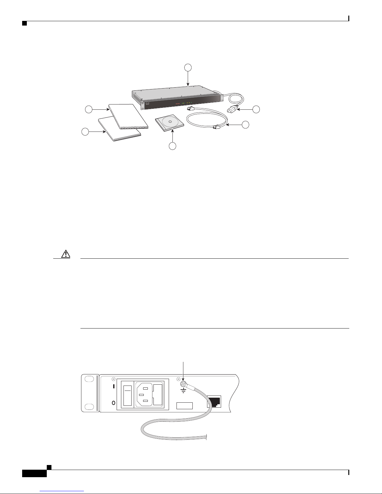
The Cisco VG30D Voice Gateway arrives supplied in a single package that contains the following items
that are shown in
1. Cisco VG30D Voice Gateway Unit
2. Mains Power Cable
3. RJ45 iSDN Crossover Stub Cable for QSIG/Q.931 connection, Port 1
4. CD-ROM with PDF versions of user documentation
5. Quick start guide
6. Safety guide
OL-19276-01
Figure 1:
Cisco VG30D Voice Gateway User Guide
2-1
Page 16
Hardware Installation
LANSTATU
S
P
o
wer
Speed
P1 P2
S0
S1
S2
S
3
T
x
D
L
i
n
k
/
R
x
D
C
i
sco VG30
D
1
2
3
4
5
6
Chapter 2 Installation
Figure 1 Package Contents
The customer must supply all other cables. For details, refer to Appendix C, “Connectors and Cabling”
of the Cisco VG30D Voice Gateway User Guide.
Store the packaging material in a clean, dry area for possible re-use.
Hardware Installation
The Cisco VG30D Voice Gateway may be either rack mounted (preferred) or used as a desktop unit.
When you are rack mounting, pay attention to cooling. The Cisco VG30D Voice Gateway has
side-to-side cooling. The design of the rack should allow for adequate airflow for either side of the unit.
Refer to the rack manufacturer’s specification for suitable mounting methods.
Caution Ensure the Cisco VG30D Voice Gateway is earthed at all times through the dedicated earth terminal on
the rear of the unit as shown in Figure 2.
The earthing cable must conform to the following specification. It shall:
- Be PVC covered green with yellow longitudinal coloured stripes as defined in EN 60950
- Be rated at 17 amps
- Have a cross sectional area of 1.5mm
- Be of stranded wire 7/0.53, and
- Be terminated with an M3 ring terminal 1-2.6 mm2 conductor
Figure 2 Earth Screw on Rear Panel
2
Earthing
Connection
DISCONNECT MAINS SUPPLY BEFORE REMOVING LID
NO USER SERVICEABLE PARTS
110 -230 VAC
60 - 50Hz
380mA
FUSE
T2A H 250V
Ethernet
10/100 Base-T
274470
Cisco VG30D Voice Gateway User Guide
2-2
OL-19276-01
Page 17
Chapter 2 Installation
Connection Sequence
To identify the ports, refer to Figure 4.
Caution Do not connect to the E1 telephony ports until first-time configuration is complete.
Step 1 Connect the earthing cable as described in the “Caution” in Hardware Installation.
Step 2 Connect the mains power cable.
Step 3 Connect the 10/100 Ethernet cable.
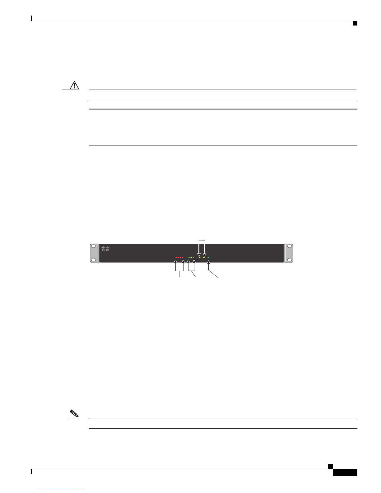
Front Panel Indicators
The Cisco VG30D Voice Gateway unit has 10 LEDs on its front panel. They show unit status information.
This section describes the front panel indicators that
Connection Sequence
Figure 3 shows.
STATUS
LAN
Figure 3 Front View
Port Active
LEDs
S0
S3
S2
S1
Status of
active port
LEDs
L
in
Speed
k/
Rx
T
x
D
D
LANSTATUS Power
Local Area
Network
LEDs
P1 P2
Power LED
(Amber in self
test, Green when
operational)
Cisco VG30D
274472
The 4 red STATUS LEDs are labelled S3, S2, S1, and S0. They indicate unit status in conjunction with
the two port LEDs, P1 and P2. During unit self-test, the status LEDs will come on and go off in sequence,
and in the event of a self-test failure, stop with one LED remaining on.
Three LEDs indicate LAN activity. The TxD LED flashes amber on transmission of a packet. The
Link/RxD LED flashes green on receipt of a packet. The green Speed LED is ON for 100 Mbit/s or OFF
for 10Mbit/s. If Ethernet is not connected, these LEDs will remain off.
Note The RxD LED will flash for any traffic on the Ethernet, regardless of destination.
OL-19276-01
Cisco VG30D Voice Gateway User Guide
2-3
Page 18
Back Panel Equipment
110 -230 VAC
60 - 50Hz
380mA
DISCONNECT MAINS SUPPLY BEFORE REMOVING LID
NO USER SERVICEABLE PARTS
Ethernet
10/100 Base-T
Factory POST
Factory Craft
Select Craft Port
FUSE
T2A H 250V
Serial No. 3277 19 5
RJ45 BNC RJ45 BNC
BNC Connectors
(75 Ohm only)
Craft
Switch
Power Supply
Unit
Earth
Impedance
Switch
Serial
Number
Craft Port
(RS232)
Ethernet
Port
POST
Switch
RJ45 Connectors
(120 Ohm only)
Alarm Port
Fuse
Impedance
Switch
274469
P1 and P2
The two amber Port LEDs are labelled P1 and P2. Together with the STATUS LEDs, they indicate unit
status. When the unit is operating normally and all is well, these LEDs turn on and off every few seconds
with all STATUS LEDs off.
When a problem exists, the Port LEDs will show the problem’s location (P1 or P2, or if both P1 and P2
are lit, a major alarm exists). The STATUS LEDs will then indicate the problem. If more than one port
has a problem, they will be shown in a cycle of 5 seconds each.
Power
The Power LED has two functions. When power is applied, it comes on amber to indicate that the unit is in
self-test mode. When the self-test satisfactorily completes, it changes to green to indicate that the unit is
functioning correctly.
Back Panel Equipment
Chapter 2 Installation
Ports
Ethernet
This section describes the Cisco VG30D Voice Gateway back panel ports and switches that are shown in
Figure 4.
Figure 4 Rear View
Use the 10/100 Base-T Port to connect to the IP Network to allow voice packets to be transmitted and
received and for a computer using a Web browser to communicate with the Cisco VG30D Voice Gateway
configuration and management interface.
2-4
Cisco VG30D Voice Gateway User Guide
OL-19276-01
Page 19

Chapter 2 Installation
Port 1 & Port 2
Craft Port
Alarm Port
Back Panel Equipment
Each port has three connectors. The two BNC connectors, which are 75-ohm unbalanced, are marked Rx
and Tx. The RJ45 connector is 120-ohm balanced. Ensure the Impedance Switch is set to the correct
impedance. You can configure parameters for each port using the Gateway Management Interface on a
Web browser.
The Craft Port exists primarily to enable a serial connection to a dumb terminal or a terminal emulation
application on a computer that is running RS-232 at 9600 baud, 8 bit, 1 stop bit, and no parity.
If required, you can connect the Cisco VG30D Voice Gateway Alarm Port to an alarm signal detector
before powering on the unit.
Switches
Power On/Off
The power On/Off switch (I / O) is adjacent to the mains connector.
Caution Before connecting any cables or changing any switches, power off the Cisco VG30D Voice Gateway.
POST
You must set the Power On Self Test (POST) switch in the POST position before powering on the Cisco
VG30D Voice Gateway unit. Only Cisco Systems, Inc., engineers use the Factory position.
Impedance Switches
This allows the selection of either 75-ohm or 120-ohm impedance for the SCN ports. Use 75 ohms for
coaxial BNC connection (BNC position), and 120 ohms for UTP RJ45 connectivity (RJ45 position).
Caution Make this selection before power is applied to the unit.
Craft Switch
Use the Craft switch to switch between serial connection for initialising the Cisco VG30D Voice
Gateway and Factory Engineering management. By default, the switch should stay set to Craft.
OL-19276-01
Cisco VG30D Voice Gateway User Guide
2-5
Page 20

Power On Self Test and IP Address Setup
Power On Self Test and IP Address Setup
On power ON of the Cisco VG30D Voice Gateway, the unit will perform a self-test. The Power LED on
the front panel shows amber, and the four STATUS LEDs come on and go off (in sequence from left to
right) to indicate that the unit is performing the self-test. These tests check the correct operation of the
hardware and start the operational software. This process should complete in less than 1 minute.
Successful Self-Test
When all the tests complete successfully and the software is operational, the Power LED changes colour from
amber to green. Approximately 30 seconds later, you can log in to the web-based Gateway Management
Interface.
The Cisco VG30D Voice Gateway has been configured with the default IP address of 192.168.1.1 and
sub-net mask 255.255.255.0.
Proceed as follows:
Step 1 Connect the ethernet port of the Cisco VG30D Voice Gateway directly to the ethernet port of a computer.
Step 2 Open a web browser and enter 192.168.1.1 directly into the IP address bar.
Chapter 2 Installation
Note You may need to change the IP address and sub-net mask of your computer to be on the same
Step 3 Log in to the Cisco VG30D Voice Gateway by using Advanced (case sensitive) for both Username and
Password.
Step 4 Browse to Configuration/Gateway/Set IP Address.
Step 5 Set Gateway Management IP Address, Set Gateway Management Subnet Mask and, if required, Set
Management Default Gateway Address and click the Submit button.
Note The set parameters will get used next time that the Cisco VG30D Voice Gateway gets re-booted,
The Cisco VG30D Voice Gateway may now be powered OFF, installed and connected to the IP network
(accessible through the new IP address). As an alternative, you may continue with further configuration
using the Gateway Management Interface as described in Sections
Gateway User Guide.
Self-Test Failure
sub-net.
but the Cisco VG30D Voice Gateway will remain accessible through the active connection until
then.
3 and 4 of the Cisco VG30D Voice
If any test in the sequence fails, the cycle of the STATUS LEDs will stop (with one LED remaining on)
and the Power LED will remain AMBER.
Cisco VG30D Voice Gateway User Guide
2-6
OL-19276-01
Page 21

Chapter 2 Installation
Power On Self Test and IP Address Setup
You can obtain details of any failures if the unit undergoes the self-test when it is connected through the
Craft Port to a dumb terminal or a terminal emulation application on a computer that is running RS-232
at 9600 baud, 8 bit, 1 stop bit, and no parity or flow control.
If an error is reported, consult Fault Determination for the appropriate corrective action or call your
support contact. After errors have been corrected, make sure that the self-test runs satisfactorily to
completion and proceed as described in
Successful Self-Test .
OL-19276-01
Cisco VG30D Voice Gateway User Guide
2-7
Page 22

Power On Self Test and IP Address Setup
Chapter 2 Installation
Cisco VG30D Voice Gateway User Guide
2-8
OL-19276-01
Page 23

Initial Configuration
Gateway Management Interface
To configure the Cisco VG30D Voice Gateway, you must now connect the Ethernet Port to the IP
Network, but do NOT connect to the E1 telephony ports yet.
You need a standard Web browser application to configure the Cisco VG30D Voice Gateway unit. Ensure
that your browser is set to accept cookies and always check for newer versions of stored pages.
You can set configuration parameters by using a simple intuitive menu as shown in Figure 3-1.
CHAPTER
3
OL-19276-01
Cisco VG30D Voice Gateway User Guide
3-1
Page 24
Access Levels
274477
Configuration
Administration
Diagnostics
Help
Logout
Set IP Address
Set Time and Date
Set PCM Clock Source
Configure SNMP Traps
Reset to Defaults
Back Up Configuration
Restore Configuration
Gateway
Applications
DPNSS Basic
DPNSS Advanced
DPNSS Services
Q.931 Basic
Q.931 Advanced
Q.931 Services
Inter-Working
System Details
System Log
Major Alarm Log
Port Error Logs
Port Error Statistics
Call Statistics
Access Control
Software Upgrade
Software Selection
Reboot the Gateway
Cisco UCM
QSIG
VoIP
ISDN
Q.931
DPNSS
Avaya
Nortel
PBX
Chapter 3 Initial Configuration
Figure 3-1 Configuration Menu Structure
Buttons on many pages provide the same function:
Submit Use this button to submit the configuration setting or change.
Refresh Use this button to refresh the page to see the original settings or to confirm the
submitted settings or changes.
Access Levels
Cisco VG30D Voice Gateway User Guide
3-2
The Cisco VG30D Voice Gateway has 3 access levels:
• Monitor
• Configure
• Advanced
Close This button takes you back to the Menu or previous pages.
OL-19276-01
Page 25

Chapter 3 Initial Configuration
Monitor level access allows the user to view the entire system configuration but prevents them from
making any changes.
Configure level access allows the user to make changes on the Application, DPNSS Basic and Q.931
Basic pages and to Back Up Configuration. At this access level, the user can view the remaining pages
but cannot change them.
Advanced level access users can make changes to any part of the configuration.
Help Facility
This facility, which is available from the Main menu, will open a separate browser window that may be
kept open at the same time as the Configuration window. However, it does not have the level of detail
of this User Guide and does not provide guidance on communications protocols.
Logout
The Logout facility is provided because only a single user may access the Cisco VG30D Voice Gateway
management interface at any one time. When a user is logged in, no other logins will be accepted.
Therefore, the user should Logout at the end of the session.
An inactivity timer is provided for when a user does not log out. This timer enables another user to log
in after a set period of inactivity in the event of a network or computer failure. The factory default value
for the Non-Use Timeout Period is 5 minutes, but it may be set between 3 and 15 minutes. When the
Non-Use Timeout Period expires, it does not log out the user. This logout occurs when another user
attempts to log in.
Help Facility
Note When using Internet Explorer, if you close the browser or navigate to another location without first
logging out, a window will pop up to ask whether you want to log out from the Gateway Management
Interface. Selecting Logout will enable another user to log in immediately. Selecting Ignore will close
the window and leave you logged in until the Non-Use Timeout Period elapses.
Access Control
Name & Password Defaults
The factory default settings for the User Name (or User ID) and Password are the same as for the levels
of access. For example, to access the interface at Monitor level, the User Name is Monitor and the
Password is also Monitor. User Name is always the level of Access. Only the Password may get
changed. Remember that the User Name and Password are case sensitive.
Cisco Systems, Inc., recommends that you change the default passwords. You can do this only when you
are logged in at the Advanced level.
OL-19276-01
Cisco VG30D Voice Gateway User Guide
3-3
Page 26

Access Control
Application Default Settings
At any time during the configuration process you can undo your settings and start again by resetting the
Cisco VG30D Voice Gateway to its default settings. Refer to
Login
To access the Gateway Management Interface, perform the following procedure:
Step 1 Enter the Management IP address of the Cisco VG30D Voice Gateway (default is 192.168.1.1) in the
Address field of your browser. When the Cisco VG30D Voice Gateway unit is located, you will be asked
to enter a User Name and a Password.
Step 2 For User Name (or User ID), enter Advanced.
Step 3 For Password, enter Advanced. An introduction screen will display.
Step 4 Click Continue and the Cisco VG30D Voice Gateway Diagnostic Overview screen (the main screen)
displays.
Chapter 3 Initial Configuration
Resetting Applications to Defaults.
Change IP Address and Name
Step 1 Select Configuration, Gateway and then Set IP Address.
Step 2 Insert new IP address at Set Gateway Management IP Address.
Step 3 If required, insert a name for the unit at Gateway Name.
Step 4 If required, you may also change the Subnet Mask and Default Gateway Address.
Step 5 Select Submit and the displayed settings will be confirmed.
Step 6 To return to the Menu, select Close .
Note Changes will take effect next time that the Cisco VG30D Voice Gateway is rebooted.
Set Time & Date
Step 1 Select Configuration, Gateway and then Set Time & Date.
Step 2 Select Synchronise with PC (if the computer clock is set correctly), or enter the correct values and then
Set with current values.
Step 3 To return to the Menu, select Close .
Cisco VG30D Voice Gateway User Guide
3-4
OL-19276-01
Page 27

Chapter 3 Initial Configuration
Change Passwords
Note Be aware that passwords are case sensitive and must consist of not less than seven and not more than ten
alphanumeric characters.
Step 1 Select Administration and then Access Control.
Step 2 Select the Access level field and enter the new password.
Step 3 Select the next field and reenter the new password.
The operation stays the same for other access levels.
Step 4 Select Submit and the Change Confirmation screen will display.
Step 5 Select Go Back to return to Access Control Settings or select Close to exit Access Control.
Note Once the password has been changed, you will not be able to change any parameters until you
Access Control
logout and login again with the new Password.
Step 6 Logout and then log in again with the new password at either the Advanced or the Configure level.
Set Non-Use Timeout Period
The Non-Use Timeout Period specifies the time that is allowed for a user to be logged in to the Gateway
Management Interface without actively using it before being automatically logged out when another user
attempts to log in. You can set it for 3 to 15 minutes.
Step 1 Select Administration and then Access Control.
Step 2 Insert a number for the Non-Use Timeout Period.
Step 3 Select Go Back to return to Access Control Settings or select Close to exit Access Control.
Logging Out
Step 1 Select Logout from the main Menu.
Step 2 Confirm that you want to log out.
Step 3 Close the browser window.
OL-19276-01
Cisco VG30D Voice Gateway User Guide
3-5
Page 28

Resetting Applications to Defaults
Note If you do not log out, another user will not be allowed to log in until the Non-Use Timeout Period
has elapsed (Refer to
Set Time & Date.). If another user is unable to log in immediately, make
sure the browser window has been closed. If necessary, close down the browser application.
You need to configure the Cisco VG30D Voice Gateway Ports. Refer to Management and Configuration.
Resetting Applications to Defaults
Refer to Reset to Defaults for a list of configuration values that will be reset. IP Addresses and Time and
Date settings will not get changed:
Should you want to reset the Cisco VG30D Voice Gateway to its default settings, perform the following
procedure:
Step 1 Select Configuration, Gateway and then Reset to Defaults.
Step 2 Select Set to Defaults.
Step 3 Select Administration from the top level Menu
Step 4 Select Reboot the Gateway.
Step 5 When the unit has rebooted, close the current Browser window and open a new one.
Step 6 Log in again. Refer to the Login section.
Chapter 3 Initial Configuration
Cisco VG30D Voice Gateway User Guide
3-6
OL-19276-01
Page 29

Gateway
Set IP Address
CHAPTER
4
Management and Configuration
This section provides an overview of all management and configuration facilities that are provided by
the Cisco VG30D Voice Gateway's Gateway Management Interface. Refer to the
Interface section.
You should have established the Cisco VG30D Voice Gateway's IP Addresses and Subnet Masks during
the initial setup process. However, you can change these addresses at any time and also insert a Default
Gateway IP Address. Leaving the Default Gateway IP Address field blank signifies that no default
gateway is to be used.
You can also give the Cisco VG30D Voice Gateway a Gateway Name, which will display beneath the
IP address at the bottom of the Gateway Management Interface configuration pages.
IP Address changes will not be effected until the Cisco VG30D Voice Gateway has been reset. You will
need to log in to the new address for any further configuration changes. Name changes take effect
immediately.
Gateway Management
Set Time & Date
You can set the time and date by entering them into the fields that are provided. You can do this by
accepting the values that are displayed or by synchronising them with your computer.
Set PCM Clock Source
You can set Clock Synchronization to Port 1 or Port 2
Configure SNMP Traps
You can enable up to eight Trap Destination Addresses by inserting the address value. To disable an
address, remove the address value.
OL-19276-01
Cisco VG30D Voice Gateway User Guide
4-1
Page 30

Gateway
Traps are grouped as follows:
• Major Alarm
• Port Errors
• Reset Traps
• System Events
• Layer 1 Alarms
To enable a group, check the box as required. To enable all groups select Enable All. Select Submit to
save any changes.
Refer to SNMP Traps for the group tables. You will find links to the MIBs that define the Cisco VG30D
Voice Gateway traps on the Gateway Management Interface page.
Reset to Defaults
This allows the user to set the following groups of the Cisco VG30D Voice Gateway configuration
parameters to their default values.
• DPNSS Basic, Advanced and Services
• Q.931 Basic, Advanced and Services
• SNMP Traps
• Inter-working
• Access Control
No change will occur to the Cisco VG30D Voice Gateway’s date and time settings, IP address, software
selection, logs, or statistics. Reboot the Cisco VG30D Voice Gateway for changes to take effect.
Chapter 4 Management and Configuration
Back Up Configuration
Caution You cannot restore backups from a Westell IiQ3000 Voice Gateway to the Cisco VG30D Voice Gateway.
You cannot restore backups from a Cisco VG30D Voice Gateway to the Westell IiQ3000 Voice Gateway.
When the Cisco VG30D Voice Gateway has been satisfactorily configured, you can back up this
configuration to an FTP server for restoring at a later date in the event of a nonrecoverable system failure.
To back up the configuration, perform the following procedure:
Step 1 From the main menu, select Configuration, Cisco VG30D Voice Gateway and
Back Up Configuration.
Step 2 Enter the FTP Server IP Address onto which the configuration is to be backed up.
Step 3 Enter the User Name and Password to access the FTP Server.
Step 4 Insert the name of the Directory on the FTP Server.
Step 5 Give your back up configuration a file name.
Step 6 Give a brief description of the configuration. Consider this step as optional.
Cisco VG30D Voice Gateway User Guide
4-2
OL-19276-01
Page 31

Chapter 4 Management and Configuration
Step 7 Press Back Up to save the file.
Step 8 When the back up is complete, press Close to return to the Main menu.
Restore Configuration
This allows a configuration that previously has been backed up to either be restored to the Cisco VG30D
Voice Gateway from which it was backed up or to be installed on another Cisco VG30D Voice Gateway
unit.
Note You can restore a configuration only to an Cisco VG30D Voice Gateway that is running the same
software and version as that on the Cisco VG30D Voice Gateway from which and when the Back up
Configuration was made.
To restore a configuration, perform the following procedure. Changes will not occur to IP addresses,
software selection, logs or statistics.:
Applications
Step 1 From the Main Menu, select Configuration, Cisco VG30D Voice Gateway and Restore
Configuration.
Step 2 Enter the IP Address of the server that contains the backup file.
Step 3 Enter a User Name and Password for the FTP server.
Step 4 Enter the Directory name that contains the backup file.
Step 5 Enter the Name and extension of the backup file.
Step 6 Click on Select and the Configuration Details window will display.
Step 7 Check that the Configuration Details are correct and compatible with the Cisco VG30D Voice Gateway
to which you are restoring or installing on and select Install.
Step 8 When the Restore is confirmed, select Close. The Cisco VG30D Voice Gateway will reboot itself.
Applications
Use the following preset applications for quick configuration:
• Cisco UCM (Cisco Unified Communications Manager)
• QSIG
• Vo I P
• ISDN
• Q.931
• DPNSS
• Avaya
• Nortel
OL-19276-01
Cisco VG30D Voice Gateway User Guide
4-3
Page 32

DPNSS Configuration
• PBX
Quick Configuration
To configure any of the preceding preset applications, perform the following procedure:
Step 1 Select Configuration and then Applications.
Step 2 Select the required application and the relevant settings will display.
Step 3 Complete the fields as required.
Step 4 Select Submit and the settings will change.
Step 5 Select Close to return to the Menu.
Note Any active ports temporarily will get deactivated while the changes are being made to the basic
configuration. Calls in progress will get lost, and service will get interupted.
Chapter 4 Management and Configuration
DPNSS Configuration
Basic Settings
Note Any changes that are made to the basic settings will cause the Cisco VG30D Voice Gateway to
temporarily deactivate the DPNSS Port. A warning will tell you that calls in progress will be lost, and
confirmation is requested before changes are submitted.
Options are:
• Activate or deactivate DPNSS Port
Puts the DPNSS port (Port 2) in or out of service.
Note You cannot activate the port if no channels are commissioned.
• Channel Commissioning (for up to 30 channels)
All channels are set to In Use when the Cisco VG30D Voice Gateway is supplied. Channels that are
not required may be decommissioned
• DPNSS A/B Orientation
Ensure the Cisco VG30D Voice Gateway is set to the opposite A/B Orientation from that of the Port
on the PBX or other equipment to which the Cisco VG30D Voice Gateway is connected.
• X or Y Channel Orientation
Ensure Channel Orientation is set opposite to the orientation for each of the Channels on the PBX
or other SCN equipment with which the Cisco VG30D Voice Gateway is communicating.
.
Cisco VG30D Voice Gateway User Guide
4-4
OL-19276-01
Page 33

Chapter 4 Management and Configuration
• Select or deselect Initiate DLC Establishment
If checked, the Cisco VG30D Voice Gateway will attempt to establish each LAP by sending
SABMEs on each commissioned channel.
• Select or deselect Clear on Establish
If checked, the Cisco VG30D Voice Gateway will send a CRM on each LAP as it is established.
• Channel Allocation - Low to High / High to Low
This dictates whether channels get allocated to calls starting at the highest or the lowest enabled
channel.
Advanced Settings
Available settings include the following:
• Proxy Diversion Service: If service is enabled and a call from the QSIG network to the DPNSS
network is diverted, the Cisco VG30D Voice Gateway will intervene to ensure that the diversion
takes place. If service is disabled, calls from the QSIG network that encounter diversion at a DPNSS
PBX are likely to fail. This setting does not affect calls from DPNSS, either to QSIG or transparently
over QSIG to other DPNSS extensions.
You can configure diversion service to act on behalf of all calls (All), a specific dialed number
(Exact), calls matching a part of the dialed number (Match) or calls that do not match (No Match)
a given part of a dialed number.
• Proxy Divert Address Filter: The filter represents the digits against which the dialed number is
matched, if the Proxy Diversion Service is set to Exact, Match or No Match.
• Operator Recall Timeout: This setting only applies if Proxy Diversion is enabled. If a call is
diverted by an Operator in the DPNSS network to a phone in the QSIG network, the phone to which
it has been diverted will ring for the number of seconds that is configured and then will revert to the
operator (unless answered). If the Operator Recall Timeout is disabled, the call will continue
ringing at the QSIG extension.
• Enable ISDX VMS Emulation: Checking this setting allows extensions on QSIG PBXs to be
integrated into a Voice Mail System (VMS) that is hosted on an ISDX PBX.
• ISDX VMS Diversion on No-reply Timer: See DPNSS Message Waiting Implementations and
ISDX Voice Messaging Systems.
• Default ISDX VMS Number: See DPNSS Message Waiting Implementations and ISDX Voice
Messaging Systems.
• ISDX VMS Diversion Count Threshold: See DPNSS Message Waiting Implementations and
ISDX Voice Messaging Systems.
• Enable Supplementary String Generation: This setting adds any supplementary service strings to
the Selection field.
• Enable Incoming Name Services: This setting allows DPNSS text strings to be mapped into Called
and Calling party names in QSIG.
• Enable Divert Messages: This setting allows DPNSS text strings to be mapped into QSIG Diversion
service messages as names.
• Enable Proxy Mapping of Calling Party Category: When Proxy Mapping of Calling Party
Category is enabled, the Cisco VG30D Voice Gateway will generate appropriate calling part
category elements from QSIG name elements.
DPNSS Configuration
OL-19276-01
Cisco VG30D Voice Gateway User Guide
4-5
Page 34

DPNSS Configuration
Chapter 4 Management and Configuration
The Calling Party Category ‘Operator’ match string, Calling Party Category ‘PSTN’ match
string, Calling Party Category ‘ISDN’ match string and the Calling Party Category ‘Decadic’
match string fields define the strings to be matched for each type CPC that can be generated in this
way.
• Segment long ISRMs: When checked, this field allows the Cisco VG30D Voice Gateway to
generate ISRM(i) - SSRM(c) sequences where the incoming Q.931 Setup message that indicates
sending complete would result in a generated ISRM(c) that is exceeding the maximum DPNSS PDU
size.
• Incoming Channel Mapping: If setting is configured to Fixed, the channel that is used by the
incoming call must get used for the outgoing call. If setting is configured to Switched, a different
channel may get negotiated in the outgoing Q.931 call, and the Cisco VG30D Voice Gateway will
switch the bearer channel internally.
• Transparent Transport Service Support: This setting enables the generation of information that
is necessary to transport the original DPNSS messaging transparently across a QSIG network.
• Re-attempt Transparency after transfer: If the box is checked, the Cisco VG30D Voice Gateway
will attempt to work transparently to a new destination following call transfer.
DPNSS Services
Configuration options include the following:
• Enable Virtual Calls: Enabling virtual calls allows the Cisco VG30D Voice Gateway to process
• SIC mapping for Telephony calls: This option allows a received “Speech” to be mapped to a Q.931
• Enable Data Calls: This option allows 64kBit unrestricted digital calls to be accepted by the Cisco
• Enable BSS-M and Enable BSS-P: These fields control the insertion of Bearer Service Selection
• Enable CLC Mapping: If CLC mapping is enabled, the Cisco VG30D Voice Gateway will attempt
• Enable RTI Mapping: If RTI mapping is enabled, the Cisco VG30D Voice Gateway will attempt
• Enable Text to Name Mapping: If option is enabled, the Cisco VG30D Voice Gateway will
• Enable Three Party Working: This option allows the Cisco VG30D Voice Gateway to operate
• Enable Call Offer: This option allows the Cisco VG30D Voice Gateway to operate DPNSS Call
• Enable Route Optimisation Service: This option allows the Cisco VG30D Voice Gateway to
• PBX accepts Route Optimisation Invite string: Normally checked, this option can get used to
• Restrict Route Optimisation Call Ref. mappings: This option can be used to limit the length of
non-bearer-related signalling used by many supplementary services.
Bearer Capability of either “Speech” or “3k1 Audio”. Additionally, progress indicators may also get
generated (“Speech + PI” or “3k1 Audio + PI”).
VG30D Voice Gateway.
(BSS) strings by the Cisco VG30D Voice Gateway.
to map received Calling Line Category information into Q.931 Progress Indicators.
to map received routing information into Q.931 Progress Indicators.
generate QSIG Name Supplementary Service invocations from DPNSS Text strings.
DPNSS Call Transfer Services.
Offer Services.
interwork the DPNSS Route Optimisation Service to the QSIG Path Replacement Service.
suppress sending ROP-INV string to a DPNSS PBX that cannot accept it by unchecking the box.
the embedded call reference when mapping it from the ROP-INV to Path Replacement.
Cisco VG30D Voice Gateway User Guide
4-6
OL-19276-01
Page 35

Chapter 4 Management and Configuration
• Enable Diversion Service: This option allows the Cisco VG30D Voice Gateway to operate
Diversion Services.
• Diversion Validation response time: This option specifies the time (in seconds) that the Cisco
VG30D Voice Gateway will wait before autonomously generating a positive response to Diversion
Validation Request from the DPNSS PBX or network.
• Enable Loop Avoidance Insertion: If option is enabled, the Cisco VG30D Voice Gateway will
insert a loop avoidance (LA) string containing the Number of Further Transits value in the outgoing
signalling.
• Loop Avoidance mapping: If option is set to Simple the DPNSS LA value gets mapped directly to
the Q.931 transit Counter, but if option is set to Enhanced it gets treated as though it is passing
through a transit PBX before it is forwarded.
• Include Loop Avoidance in CRM: If the treatment of the LA results in the call clearing and this is
checked, the LA string will get included in the Clear Request Message that is generated by the Cisco
VG30D Voice Gateway.
• En-bloc Call Forward Digit Count: You can use this option to turn overlap dialed DPNSS calls
into en-bloc calls. When the specified number of digits has been received, the call gets forwarded
en-bloc. Be aware that this is only appropriate for networks with fixed-length dial plans.
• En-bloc Call Forward Timeout: This option acts as an interdigit timer that will forward the call
when it expires. It restarts as each digit arrives. This option proves suitable for networks with
variable-length dial plans, but introduces a post dial delay.
• Default Destination Address: You can use this field to provide a default destination address when
no dialed digits are received from the Q.931/QSIG PBX or network.
• Number of leading Destination Digits to strip: You can use the Cisco VG30D Voice Gateway to
strip leading digits such as node numbers from the dialed number, if required.
• Enable Service Spoofing: If this option is enabled, Transfer Hold and Diversion Validation Service
may get spoofed on behalf of the Q.931 network. (The services must also be enabled.)
• Three Party Working EEM Spoofing: When this option is enabled, the Cisco VG30D Voice
Gateway will generate EEM messages to resolve interaction between spoofed Transfer and ROP
services.
Q.931 Configuration
Q.931 Configuration
Basic Settings
Note Any changes that are made to the basic settings will cause the Cisco VG30D Voice Gateway to
temporarily deactivate the Q.931 Port. A warning will be given that calls in progress will be lost, and
confirmation is requested before changes are submitted.
Options include the following:
• Activate Q.931 Port 1: Checking this option puts the Q.931 port (Port 1) in service.
• Layer 1 Framing: Select CRC4 or Double Frame layer 1 Framing.
• Orientation: Select User or Network end for layer 2 framing to be the opposite of the connected
PBX or network.
OL-19276-01
Cisco VG30D Voice Gateway User Guide
4-7
Page 36

Q.931 Configuration
• Initiate Link Establishment: This option determines how the link layer (layer 2) will be
established. Select Never if the connected equipment will always initiate link establishment. Select
Immediate if the Cisco VG30D Voice Gateway is to initiate the link, or select Call if the Cisco
VG30D Voice Gateway has only to establish the link if it has a call to deliver and the link layer has
not yet been established.
• Action on Layer 2 Reset: The Cisco VG30D Voice Gateway may react to a layer 2 reset or loss and
re-establishment of the link in three ways while calls are in progress. The response may be to Ignore
the layer 2 event, to send a Status message for each active call, or to send a Status Enquiry message
for each call.
• Overlap Signalling Support: The support for overlap dialed calls can be configured to:
–
–
–
–
Advanced Settings
Chapter 4 Management and Configuration
None when calls in both directions will be converted to en-bloc
Incoming when incoming calls overlap, outgoing calls will be converted to en-bloc
Outgoing when outgoing call overlap, incoming calls will be converted to en-bloc, or
Both Ways when all calls are treated as overlap calls.
Available settings include the following:
• Layer 3 Protocol Profile: Select the protocol type from QSIG - (ETSI QSIG 1995), Euro-ISDN
(ETS300-403-1), AT&T TR-41449, or ETSI (Generic Q.931).
• Service Message Supported: Valid only in TR41449 profile, if checked this flag controls the
response to a Service message with global call reference that is being received. The Cisco VG30D
Voice Gateway will respond with Service Ack message if option is enabled or a Status message with
cause of Message Not Implemented if disabled.
• Call Reference Length: Setting allows the Cisco VG30D Voice Gateway to accept one-octet or
two-octet Call references. If Single is selected, the Cisco VG30D Voice Gateway will only send and
receive one octet length call references. If Double is selected, only call references that are two octets
in length will be deemed valid. When Both is selected, the Cisco VG30D Voice Gateway will accept
either length for incoming calls and generate two-octet Call References on outgoing calls.
• Send Sending Complete Element: Unchecking the box allows the Sending Complete Information
Element to be suppressed in outgoing en-bloc calls.
• Send Connected Number Element: Unchecking the box allows the Connected Number
Information Element to be suppressed in outgoing Connect messages.
• Enable Calling Line Id: Unchecking the box allows the Calling Party Number Information Element
to be suppressed in outgoing messages.
• Connected Number Element Identifier: This setting allows the encoding to be selected according
to the connected network requirements. 76/0x0C provides compatibility with older TR41449
implementations that use that coding.
• Include Octet 3a in Connected Number: Checking this box will enable the transmission of
Presentation and Screening Indicators in Connected Number Information Elements.
• Support Progress Indicator in Call Proc. and Disconnect: Checking this box will enable any
available progress information to be sent in Call Proceeding and Disconnect messages.
Note Some types of networks do not support Progress Indicator in Call Proc. and Disconnect.
Cisco VG30D Voice Gateway User Guide
4-8
OL-19276-01
Page 37

Chapter 4 Management and Configuration
• Support ECMA Progress Description Codes: Checking this box will allow the Cisco VG30D
Voice Gateway to process ECMA progress description codes in addition to the default ITU-T codes.
• Change Status Element Supported: Checking this box enables the Cisco VG30D Voice Gateway
to process Change Status Information elements.
• Channel Preference for Outgoing Calls: This setting controls the encoding of the outgoing
Channel Id Information Element and the behaviour of the Cisco VG30D Voice Gateway when
requested channels are unavailable. Set to Preferred if you are using switched channel mapping.
Otherwise, use Exclusive.
• Incoming Channel Mapping: If this setting is configured to Fixed, the channel that is used by the
incoming call must be used for the outgoing call. If this setting is configured to Switched, a different
channel may be used in the outgoing Q.931 call, and the Cisco VG30D Voice Gateway will switch
the bearer channel internally.
• B-channels Initial State: This setting sets the initial state of each channel to either Free (and
in-service) or Out of Service.
• Response to Status Enquiry in Null-State: This setting sets the response of the Cisco VG30D
Voice Gateway to an incoming Status Enquiry message received when the call is in the NULL state.
The Cisco VG30D Voice Gateway may respond by sending either a Release Complete message or a
Status message.
• Response to Status Enq. with Global Call Ref: This setting sets the response of the Cisco VG30D
Voice Gateway to an incoming Status Enquiry message with the Global call Reference. The Cisco
VG30D Voice Gateway may be configured to Always Null and ignore the message or Send Status
to send the message.
• Send Status to Errored Optional Elements: This setting dictates whether the Cisco VG30D Voice
Gateway should send a Status message in response to a message that contains an errored Information
Element. If it sends the status message, this setting dictates whether it should be the call status
Before Processing or After Processing the received message.
• Clear Forward if No Response to Setup: This parameter allows the Cisco VG30D Voice Gateway
behaviour on expiry of the Q.931 T303 timer to be specified. The Cisco VG30D Voice Gateway may
be configured to Always send Release Complete forward, Never send it, or send when configured
as the Network end only.
• Symmetrical Call State: When this setting is checked, call state reported in Status messages will
be QSIG. Otherwise, the Cisco VG30D Voice Gateway will report Q.931 user or Network end state
dependent on configuration.
• En-bloc Call Forward Digit Count: Overlap dialed Q.931/QSIG calls can be turned into en-bloc
calls. When the specified number of digits has been received, the call gets forwarded en-bloc. This
is only appropriate for networks with fixed-length dial plans.
• En-bloc Call Forward Timeout: This setting acts as an interdigit timer that will forward the call
when it expires. It gets restarted as each digit arrives. This setting proves suitable for networks with
variable-length dial plans but introduces a post dial delay.
Q.931 Configuration
Q.931 Services
Configuration options include the following:
• Enable Call Independent Signalling: This option allows the Cisco VG30D Voice Gateway to
process non-bearer-related signalling necessary for supplementary services operation.
OL-19276-01
Cisco VG30D Voice Gateway User Guide
4-9
Page 38

Q.931 Configuration
Chapter 4 Management and Configuration
• Enable Call Forwarding Service: This option enables or disables acceptance and generation of
QSIG Call Forwarding Services.
• Enable Call Transfer Service: This option enables or disables acceptance and generation of QSIG
Call Transfer Services.
• Enable Call Offer Service: This option enables or disables acceptance and generation of QSIG Call
Offer Services.
• Enable Call Completion Service: This option enables or disables acceptance and generation of
QSIG Call Completion Services.
• Enable Message Waiting Indication Service: This option enables or disables acceptance and
generation of QSIG Message Waiting Services.
• Enable Name Identification Service: This option enables or disables acceptance and generation of
QSIG Name Identification Services.
• Name Text to Display element Mapping: This option disables or controls the direction in which
DPNSS text strings and the QSIG Name Supplementary service are mapped. Options include: No
mapping, Display to Name Text, Name Text to Display or Name Text to/from Display.
• Spoof Connected Name Elements: Checking the box allows a previously received Called Party
Name or Alerting Party Name to be used as the Connected Name, if none is received.
• Diversion Mapping: This option selects which QSIG services will generate a DPNSS Diversion
Request. Options include: No mapping, Redirect, Redirect and Call Fwd or Call Forward.
• Enable ETSI Party Category Generation: Checking the box enables ETSI Party Category codes
as well as ITU-T codes to be accepted.
• Enable Path Replacement Service: Checking the box enables acceptance and generation of QSIG
Path Replacement Services.
• Enable Path Retain Service: Checking the box enables acceptance and generation of QSIG Path
Retain Services.
• Transit Counter Mapping: If Transit Counter Mapping is set to Simple the Q.931 Transit Counter
value gets mapped directly to the DPNSS Loop Avoidance SIS. If it is set to Enhanced, it gets
treated as though it is passing through a transit PBX before it is forwarded. It may also indicate
Disabled.
• Transit Counter Insertion: If the box is checked, the Cisco VG30D Voice Gateway will insert a
Transit Counter Information element with the value that is defined in Maximum Transits.
• Maximum Transits: If the box alongside Transit Counter Insertion is checked, the Cisco VG30D
Voice Gateway will insert a Transit Counter Information element with the defined value.
• Transparent Transport Service Support: This option enables the generation of information that is
necessary to transport the original Q.931/QSIG messaging transparently across a DPNSS network.
Options include: Disabled, Generate or Carry.
• Facility Element Coding Standard: This option allows the selection of ISO, ETSI or ECMA
encoding and decoding of Facility Information Elements.
• Invoke Identifier Length: This option sets the length of ROSE Components Invoke Identifiers to
be generated and received by the Cisco VG30D Voice Gateway. It may be set to 1 or 2.
• Default Outgoing Calling Number Plan: This option gets used to force a particular number type
and plan in Called and Calling Party Number Information Elements. Options include: No Default,
Unknown, ISDN/E.164, Data/X.121,: Telex/F.69, National or Private.
Cisco VG30D Voice Gateway User Guide
4-10
OL-19276-01
Page 39

Chapter 4 Management and Configuration
• Default Outgoing Calling Number Type: This option gets used to force a particular number type
and plan in Called and Calling Party Number Information Elements. Options include: No Default,
Unknown, L2 Regional, L1 Regional, Private, Local, International, National, Network
Specific, Subscriber or Abbreviated.
• Default Outgoing Called Number Plan: This option gets used to force a particular number type
and plan in Called and Calling Party Number Information Elements. Options include: No Default,
Unknown, ISDN/E.164, Data/X.121, Telex/F.69, National or Private.
• Default Outgoing Called Number Type: This option gets used to force a particular number type
and plan in Called and Calling Party Number Information Elements. Options include: No Default,
Unknown, L2 Regional, L1 Regional, Private, Local, International, National, Network
Specific, Subscriber or Abbreviated.
• Insert Default Destination Address: This box needs to be checked if a Default Destination
Address is used.
• Default Destination Address: This option gets used to provide a Called Party Number when no
dialed digits are received from the DPNSS PBX or network.
• Reject Diversion Requests for Numbers longer than: The Cisco VG30D Voice Gateway will
reject diversion requests if the Destination Address is longer than the specified number of digits.
Interworking
Interworking
Interworking configuration options include the following:
• Call Completion enabled: If box is checked, this enables the interworking of QSIG Call
• Message Waiting option: Use this option to specify the way in which Message Waiting
• Facility Element coding: Facility elements that are generated by the interworking task may get
• Message Waiting NSI option: The Non Standard Information (NSI) that is used by various PBXs
• Message Waiting ON NSI string: This option will represent the default string for the Message
• Message Waiting ON call centre number: If MD110 or Both are selected in the Message Waiting
Completion services into DPNSS Call Back when Free and Call back when Next Used.
Supplementary service is interworked. The Cisco VG30D Voice Gateway can support interworking
DPNSS into pure Q.Sig, the Cisco Call Manager method (which requires the CCM Message
Waiting ON number and the CCM Message Waiting OFF number to be provided), attempt to
perform Both methods, or None.
encoded by using the ETSI or ISO standard.
may be generated by the Cisco VG30D Voice Gateway. The strings that are used by ISDX and
MD110 PBXs are provided, or the user may specify any other string by selecting Raw. Refer to
DPNSS Message Waiting Implementations for further information.
When MD110 is selected, the user must also specify the Message Waiting ON call centre number
and the Message Waiting OFF call centre number.
When Raw is selected as the Message Waiting NSI option, the user must specify the entire SIS used
by the recipient DPNSS PBX in the Message Waiting ON NSI string and Message Waiting OFF NSI
string fields.
Waiting NSI option unless Raw has been selected, when the user must insert the string to a
maximum of 30 characters.
NSI option, the user may insert up to a 10 character call centre number.
OL-19276-01
Cisco VG30D Voice Gateway User Guide
4-11
Page 40

Administration
• Message Waiting OFF NSI string: This option will be the default string for the Message Waiting
NSI option unless Raw has been selected, when the user must insert the string to a maximum of 30
characters.
• Message Waiting OFF call centre number: If MD110 or Both are selected in the Message
Waiting NSI option, the user may insert up to a 10-character call centre number.
• CCM Message Waiting ON number: This destination address must be provided when a DPNSS
voice mail system is attempting to send MWI notifications to phones that are controlled by Cisco
Unified Communications Manager.
• CCM Message Waiting OFF number: This destination address must be provided when a DPNSS
voice mail system is attempting to send MWI notifications to phones that are controlled by Cisco
Unified Communications Manager.
• DPNSS Message Waiting Call Back Messaging string: This option specifies the encoding of Call
Back Messaging - Request (CBM-R) and Call Back Messaging - Cancel (CBM-C) SIS strings.
Administration
To access Administration functions, you must have Advanced Access.
Chapter 4 Management and Configuration
Access Control
Access Control settings allow the user passwords and Non-Use Timeout Period to be set. Alphanumeric
characters, with the exception of space, are legal for passwords. The Non-Use Timeout Period specifies
the time that is allowed for a user to be logged into the Gateway Management Interface without actively
using it before being automatically logged out when another user attempts to log in. It may be set from
3 to 15 minutes.
Software Upgrade
The Cisco VG30D Voice Gateway gets supplied with an embedded default operational software. It can
only get upgraded with software that is of the same type as the embedded software.
Software Upgrade allows a new version of the software application to be downloaded to the Cisco
VG30D Voice Gateway by using an FTP server.
The IP address of the FTP server, a User Name and a Password are all required to access the FTP server.
The directory and filename of the new application on the FTP server is also required. Selecting
Upgrade will download the new application to the Cisco VG30D Voice Gateway.
This new application will overwrite an existing previously downloaded application but not the default
application. The new application will run next time the Cisco VG30D Voice Gateway is reset, but only
if the new software has been selected by using the Software Selection facility. Instructions on installing
the software version will be provided with the new software.
Configuration Backups
Be aware that configuration backups are release specific. After the software upgrade completes
successfully and is operational on the unit, a new configuration backup should be saved.
The procedure is as follows:
Cisco VG30D Voice Gateway User Guide
4-12
OL-19276-01
Page 41

Chapter 4 Management and Configuration
Step 1 Upgrade to the new version of the software.
Step 2 Select the version of the software to run next time the unit is restarted.
Step 3 Restart the Cisco VG30D Voice Gateway unit. The configuration that is stored on the unit automatically
gets loaded into the new version of software.
Step 4 Perform a Back Up Configuration as described in the Gateway section. A configuration backup file that
is compatible with the newly activated software gets produced.
Note You cannot restore a backed-up configuration file to a system that is running a different version of
software to that under which the backup file was saved.
Note Cisco Systems, Inc., recommends that each backup configuration file be given a unique name that
includes the software release number. This will ensure that, if the configuration backup files are stored
in a central location, a new backup file does not overwrite an existing file that may be required for a
different location.
Administration
Software Selection
The Cisco VG30D Voice Gateway comes supplied with an embedded default operational software.
Software Selection provides a choice between using the new software downloaded or the embedded
default software that is supplied with the Cisco VG30D Voice Gateway.
Reboot the Cisco VG30D Voice Gateway
Selecting Reboot the Cisco VG30D Voice Gateway will, after confirming the action, immediately halt
and restart the Cisco VG30D Voice Gateway.
Note Be aware that this action is service affecting. Calls in progress will get lost and service will be
interrupted until the Cisco VG30D Voice Gateway is fully operational again.
OL-19276-01
Cisco VG30D Voice Gateway User Guide
4-13
Page 42

Administration
Chapter 4 Management and Configuration
Cisco VG30D Voice Gateway User Guide
4-14
OL-19276-01
Page 43

General
CHAPTER
5
Diagnostics
The Gateway Management Interface produces logs for System, Major Alarm, and Port Errors and
statistics for Port Errors and Calls.
You can print information in management diagnostics screens. As an alternative, by using the Select All,
Copy and Paste facilities in the Web browser, you can export the information in ASCII text to other
applications.
Note If the system is set to Factory Defaults and the Cisco VG30D Voice Gateway is rebooted, all the logs
will get cleared, and the information other than the System Log will get lost.
System Details
System Log
System Details provide hardware and software information for the Cisco VG30D Voice Gateway unit.
You will need to be able to refer to this information when you communicate with the Helpdesk for
support.
The system log is created and updated dynamically. It records the date and time of certain system events,
including system crashes, automatic reboots, and manual restarts. Successful and attempted logins get
recorded.
Table 5-1 defines the various events that may get generated by the Cisco VG30D Voice Gateway and get
written to the System Log during operation. Event classifications indicate their seriousness. Events get
classified at the following four levels:
• Critical
• Major
• Minor
• Informational.
Critical indicates an event that has caused the Cisco VG30D Voice Gateway to restart. Always report
these events your supplier. Error codes for critical events include 1, 2, 303 and 601.
OL-19276-01
Cisco VG30D Voice Gateway User Guide
5-1
Page 44

Chapter 5 Diagnostics
General
Major indicates an event that will cause calls to fail. In some cases, remedial action is possible and
should be attempted before contacting your supplier.
Minor indicates an event that may have caused a single call or few calls to fail.
Informational indicates an event that contains information that may be useful but does not require any
action.
Content in Tabl e 5-1 appears in order of error code number.
Ta b l e 5-1 System Log Events
Error Code Log Description Seriousness Meaning Automatic Action User Action
1 Internal error,
Gateway will
reboot.
2 Watchdog timeout Critical A software error
400 System is starting Informational The gateway
Critical A software error
occurred from
which the gateway
could not recover.
occurred from
which the gateway
could not recover.
restarted due to
power on, or
software error, or
The gateway
restarts and an
entry gets written
to the log.
The gateway
restarts and an
entry gets written
in the log.
An entry gets
written to the log
and an SNMP trap
gets generated.
Report problem to
your supplier.
Report problem to
your supplier.
None
reboot requested
by user.
600 Reboot requested
by user
Informational The user requested
that the gateway be
restarted.
The gateway
restarts, an entry
gets written to the
None
log, and an SNMP
trap gets
generated.
601 Recovered from
SCN fatal error
602 The application
configuration has
been reset to
default values
Critical A software error
occurred from
which the gateway
could not recover.
Informational The user requested
that the Gateway
configuration be
reset to factory
default.
The gateway
restarts, and an
entry gets written
to the log.
The configuration
gets reset to
factory default, an
entry gets written
to the log, and an
Report problem to
your supplier.
None
SNMP trap gets
generated.
603 A user has logged
in to Web
management
Informational The IP address of
everyone who
logged into the
gateway’s
An entry gets
written to the log
and an SNMP trap
gets generated.
None.
management
system is recorded.
Cisco VG30D Voice Gateway User Guide
5-2
OL-19276-01
Page 45

Chapter 5 Diagnostics
Table 5-1 System Log Events (continued)
Error Code Log Description Seriousness Meaning Automatic Action User Action
604 A user logged out
of Web
management.
Informational Everyone who
logged out of the
gateway’s
management
An entry gets
written to the log,
and an SNMP trap
gets generated.
None.
system gets
recorded.
605 A user failed to log
in to Web
management
Informational A login attempt to
the gateway failed.
An entry gets
written to the log,
and an SNMP trap
None.
gets generated.
608 Automatic reboot
occurred after
configuration was
restored from
backup file
Informational Configuration got
successfully
restored from a
backup file.
The gateway’s
configuration gets
changed, an entry
gets written to the
log, an SNMP trap
None.
gets generated, and
the gateway
restarts.
609 Failed to restore
configuration from
backup file
Minor Corruption
occurred in
configuration file
or attempt to
restore to a
different software
revision occurred.
An entry gets
written to the log,
and an SNMP trap
gets generated.
Check that the
software revision
of the gateway and
configuration file
match. If this does
not solve your
problem, contact
your supplier.
610 System date/time
set
Informational The gateway date
and time changed
An entry gets
written to the log.
None.
by use of the Web
management.
816 System date/time
set from craft menu
Informational The gateway date
and time got
An entry gets
written to the log.
None.
changed by use of
the Craft menu.
General
OL-19276-01
Error Code
LogDescription
Seriousness
Meaning
AutomaticAction
UserAction
Cisco VG30D Voice Gateway User Guide
5-3
Page 46

Ports
Ports
Major Alarm Log
The SCN Major Alarm Log records the Date, Time and a Description of hardware errors.
You can clear the log by using the Clear button that is provided. You cannot recover data that is cleared.
You may want to print or export this information as ASCII text as described at the start of this section.
Port Error Logs
Logs get created dynamically for each SCN Port. For each error, the log records the Date, Time and a
brief Description.
You can clear the log for any port by using the button that is provided. You cannot recover data that is
cleared. You may want to print or export this information as ASCII text as described at the start of this
section.
Chapter 5 Diagnostics
Port Error Statistics
For each Port, SCN Port Error Statistics records the number of each of the following error types:
• Framing
• Loss of Synchronisation
• Loss of Signal
• Receiving RAI
• Receiving and Transmitting AIS
• Positive and Negative Frame Slips
• Degraded and Errored Seconds.
You can clear the statistics for any port by using the button that is provided. You cannot recover data that
is cleared. You may want to print or export this information as ASCII text as described at the start of this
section.
Call Statistics
For each Port, SCN Call Statistics records the number of each of the following call types:
• Current and Peak Active Calls
• Incoming and Outgoing Voice Calls
• Total Incoming and Outgoing Calls
• Incoming and Outgoing Collisions
You can clear statistics by using the button that is provided. You cannot recover data that is cleared. You
may want to print or export this information as ASCII text as described at the start of this section.
Cisco VG30D Voice Gateway User Guide
5-4
OL-19276-01
Page 47

CHAPTER
Conversions and Transparency
Q.931/DPNSS Conversion Configuration
Q.931 Port 1 Configuration
Basic Configuration
The default setting of the Q.931 port at Layer 2 (Q.921) specifies USER End. You must configure this
with inverse orientation to the attached equipment/network.
As the default, the Cisco VG30D Voice Gateway causes a Layer 2 RESET on recovery after physical
layer failures. This causes all calls to be cleared when a Channel 0 fault is notified. Alternatively, you
can configure the Cisco VG30D Voice Gateway to ignore Layer 1 fault indications and rely on periodic
Layer 2 status polling to detect link problems.
6
Protocol Orientation
The Layer 3 orientation gets set automatically according to the profile and Layer 2 orientation.
Action on Link Layer RESET
As the default, the Cisco VG30D Voice Gateway takes action to validate Q.931 call status for all fully
active calls on notification of a Link Layer RESET. Calls only get cleared if they are not fully set up or
a discrepancy exists in call state.
You can configure this to cause all calls to be cleared when a Layer 2 fault is notified, regardless of their
state. If the glitch sensitivity has been reduced in Channel 0 configuration, you may want to clear calls
after a fault is finally notified. Status validation should be adequate in most cases.
Overlap Signalling Support
If the Q.931 network/equipment supports overlap signalling, enable it by selecting Incoming for overlap
from Q.931, Outgoing for overlap towards Q.931, or Both Ways.
For transparent signalling, set overlap signalling to Both Ways.
OL-19276-01
Cisco VG30D Voice Gateway User Guide
6-1
Page 48

Q.931/DPNSS Conversion Configuration
DPNSS Networks in the UK typically support overlap signalling for all calls. You can make the Cisco
VG30D Voice Gateway block up incoming digits from DPNSS by setting this option to None or
Incoming. In isolated cases, it may be appropriate to turn on preemptive call forwarding in the Q.931
stack. This action very rarely is required. However, if it is needed, it operates as described in
Port 2 Configuration.
If the En-bloc Call Forwarding Timeout in Advanced Configuration is set to 0, the normal Q.931 T302
timer runs to clear incomplete calls after 15 seconds without dialling activity.
Advanced Configuration
Q.931 Profile Selection
You can profile the Q.931 port to conform to ETSI, AT&T (TR 41449), Euro-ISDN or QSIG definitions.
The default is QSIG.
For DPNSS/QSIG transparency the Layer 3 protocol Profile must get set to QSIG.
The ETSI profile is based on ETSI Specification ETS 300 102-1,). The Euro-ISDN profile is based on
the same specification, with amendments applied in ETSI specification ETS 300 102-1/A2. The
differences between the ETSI and Euro-ISDN profiles relate to the content of messages. No changes
occur to call setup and clear-down.
Cisco Systems, Inc., recommends that Euro-ISDN profile be used when you are not configuring the
Cisco VG30D Voice Gateway for transparency, irrespective of a requirement for TBR-4 compliancy.
Choose the ETSI profile only where TBR-4 compliancy is not required and where the Euro-ISDN profile
is deemed to be incorrect. Where TBR-4 compliance is required, you must choose the Euro-ISDN
profile.
Each profile sets particular defaults, appropriate to the standard definition, but these values can then be
overridden by specific action, which allows customisation of the interface to non-standard equipment
implementations. The rest of this section discusses these override options.
Chapter 6 Conversions and Transparency
DPNSS
Services Configuration
Default Destination Address
When you are operating into a DPNSS-based public network, which may address to the subscriber
number only with no private network extension number, you must ensure that a private network
extension number is supplied. This enables non-DDI calls to get directed to a sensible destination such
as the common operator. Normally, this would occur in the Q.931 PBX. However, in Cisco VG30D Voice
Gateway AT&T and QSIG implementations, it can get configured to be supplied by the Converter.
By default, non-DDI calls get a Q.931/QSIG Called Party Address of 0 as the ubiquitous operator
number. You can customize this forwarding address by configuring the appropriate private network
number, including any node address, as the Default Destination Address.
You do not need the Default Destination Address for transparency.
Cisco VG30D Voice Gateway User Guide
6-2
OL-19276-01
Page 49

Chapter 6 Conversions and Transparency
DPNSS Port 2 Configuration
Basic Configuration
The default setting of Level 2 for the DPNSS port specifies A end. Ensure that this is configured with
inverse orientation to the attached equipment/network.
Sub-Configured Links
You can configure DPNSS channels individually for operational service (that is, the DPNSS link can be
sub-configured). Q.931 calls will only get generated or accepted on those channels for which an
equivalent DPNSS channel is configured.
Contention (Glare) Resolution
When all channels on the associated DPNSS link are configured as X, the DPNSS equipment, being the
Y end, gives precedence to incoming calls, so most channel contention problems get resolved in the
DPNSS network.
Similarly, it is advantageous though not mandatory, if Cisco VG30D Voice Gateway can be configured
as the “Network” end of the Q.931 link. This is because this gives it precedence for calls over the
attached “User” end equipment.
Reduce channel contention (glare) problems further by influencing the choice of alternative channel.
Select High to Low or Low to High as the Channel Allocation option, when you are configuring the
DPNSS stack. High to Low causes the highest free channel to be selected, and Low to High causes the
lowest free channel to be selected.
Q.931/DPNSS Conversion Configuration
Services Configuration
Default Private Network Number
When you are operating into a Q.931-based public network, which may address calls to the subscriber
number only, with no private network extension number, you must ensure that a private network
extension number is supplied, so that non-DDI calls get directed to a sensible destination such as the
common operator. Normally, this would be done in the DPNSS PBX, but you can configure it to be
supplied by the converter.
By default, non-DDI calls are receive a DPNSS Called Line Identity of 0, as the ubiquitous operator
number. You can customize this forwarding address by configuring the appropriate private network
number, including any node address, as the Default Destination Address.
You do not need the Default Private Network Number for transparency.
Destination Address Editing
You can edit the destination address that is associated with calls from DPNSS before the address passes
out to Q.931, by discarding up to three leading digits. For example, a leading 9 inserted to cause the call
to be routed to an outgoing public trunk can get stripped before the call passes to the ISDN by setting
Number of Destination Digits to Strip to 1.
No requirement exists for Address Editing when you are using transparency.
OL-19276-01
Cisco VG30D Voice Gateway User Guide
6-3
Page 50

Chapter 6 Conversions and Transparency
DPNSS/QSIG Transparency Options Configuration
Preemptive Call Forwarding
Depending on whether the Q.931 implementation to which the Cisco VG30D Voice Gateway is
interfaced fully supports overlap signalling, you may need to configure the En-bloc Call Forward
Timeout and/or En-bloc Call Forward Digit Count parameters in the DPNSS stacks.
The converter uses these call forwarding parameters when overlap signalling is encountered from
DPNSS to Q.931. The converter uses these parameters to recognise when no more digits are forthcoming
and to indicate address completion and speed call setup. You should include any edited-out digits in the
count of address digits after which the call must get forwarded. They are not normally required when
you are interfacing into a public network because the network preempts such contrivances.
In both cases, a value 0 turns the address-phase termination function off. The En-bloc Call Forward
Timeout represents an interdigit timer.
You do not need this feature for transparent signalling.
DPNSS/QSIG Transparency Options Configuration
Transparent operation between Cisco VG30D Voice Gateway systems across a QSIG or DPNSS network
does get supported.
Caution Never use this feature in conjunction with Cisco Unified Communications Manager.
QSIG Transparency Through a DPNSS Network
To configure the Cisco VG30D Voice Gateway to enable QSIG Transparency through a DPNSS network,
in the Gateway Management Interface, perform the following procedure:
Step 1 Go to Configuration / DPNSS Services.
Step 2 Enable Virtual Calls by checking the box.
Step 3 Enable Data Calls by checking the box and click SUBMIT.
Step 4 Go to Configuration / DPNSS Advanced.
Step 5 Set Transparent Transport Service Support to Carry and click SUBMIT.
Step 6 Go to Configuration / Q.931 Services.
Step 7 Set Transparent Transport Service Support to Generate and click SUBMIT.
DPNSS Transparency Through a QSIG Network
To configure the Cisco VG30D Voice Gateway to enable DPNSS Transparency through a QSIG network,
in the Gateway Management Interface, perform the following procedure:
Step 1 Go to Configuration / Q.931 Advanced.
Step 2 Set Layer 3 protocol Profile to QSIG and click SUBMIT.
Cisco VG30D Voice Gateway User Guide
6-4
OL-19276-01
Page 51

Chapter 6 Conversions and Transparency
Step 3 Go to Configuration / Q.931 Services.
Step 4 Enable Call Independent Signalling. by checking the box.
Step 5 Set Facility Element Coding Standard to ISO or ETSI.
Note Ensure it set the same at both ends.
Step 6 Set Transparent Transport Services Support to Carry and click SUBMIT.
Step 7 Go to Configuration / DPNSS Advanced.
Step 8 Set Transparent Transport Service Support to Generate and click SUBMIT.
Advanced Service Interworking
Advanced Service Interworking
DPNSS Message Waiting Implementations
Message Waiting service does not get defined in DPNSS. Therefore, it is not always possible to find an
interworking service match. Various manufacturers define proprietary signalling for turning ON and
OFF Message Waiting indicators, or use the DPNSS Call Back Messaging service for this purpose. To
configure the Cisco VG30D Voice Gateway to interwork QSIG Message Waiting with some common
PBXs, go to Configuration / Inter-Working.
Table 6-1 shows what should get selected for the various manufacturer’s products for Message Waiting
NSI option on the Interworking Configuration window.
Table 6-1 Message Waiting NSI Options for Various Manufacturer’s PBXs
PBX Message Waiting NSI option
Siemens iSDX and Realitis ISDX
Ericsson MD110
Mitel Default
Avaya Definity (as a DPNSS PBX) ISDX
If your network requires a Call Centre id, enter the
Message Centre numbers that will get appended
automatically to the signalling string
No special configuration is necessary. Mitel PBXs
use the DPNSS Call Back Messaging that is
preconfigured into the Cisco VG30D Voice
Gateway.
OL-19276-01
Cisco VG30D Voice Gateway User Guide
6-5
Page 52

Advanced Service Interworking
Table 6-1 Message Waiting NSI Options for Various Manufacturer’s PBXs
PBX Message Waiting NSI option
Nortel PBXs (e.g. Meridian) ISDX
Other PBXs Try Default first (DPNSS Call Back Messaging is
preconfigured into the Cisco VG30D Voice
Gateway). If necessary, next try ISDX or call
Support for further advice if preset strings do not
work for your network. You can enter
user-defined strings by selecting Raw.
DPNSS Networks Containing PBXs from More than One Manufacturer
You can combine some options that are described in preceding sections. By selecting BOTH in the
Message Waiting NSI option, Ericsson, Mitel, Nortel, and Siemens (GPT) PBXs will get covered.
Contact Support for further advice.
Chapter 6 Conversions and Transparency
ISDX Voice Messaging Systems
Siemens implemented proprietary extensions to DPNSS Diversion to achieve better integration with
their voice messaging servers (VMSs). You can configure the Cisco VG30D Voice Gateway to attempt
to interwork these extensions with the QSIG Call Forwarding service. However, in some cases,
interworking is partial.
In iSDX/Realitis networks where a single VMS, ensure the Cisco VG30D Voice Gateway is configured
with the SPIDG address (the Logical Extension Identifier for the VMS hunt group - sometimes called
the RFD address). This is unnecessary in multiple VMS networks, where the PBXs assert the required
number explicitly in their RFD signalling. ISDX VMS parameters get set up on the DPNSS Advanced
page.
Cisco VG30D Voice Gateway units have further advanced configuration options. Your support
organisation may direct you to use these options to resolve specific VMS interworking problems. The
default configuration settings remain correct for most networks.
Name Mapping
Cisco VG30D Voice Gateway units support both the Q.931 display element to transfer name information
(in either direction) and the QSIG Name Identification service options.
The most prevalent use of the display element option is by media gateway (DE30+) cards that are
attached to the Cisco Unified Communications Manager, supporting Q.931 protocol (not QSIG).
DPNSS
Step 1 Go to Configuration / DPNSS Services
Step 2 Check the box alongside Enable Text to Name Mapping and click SUBMIT.
Cisco VG30D Voice Gateway User Guide
6-6
OL-19276-01
Page 53

Chapter 6 Conversions and Transparency
QSIG
Step 1 Go to Configuration / Q.931 Services
Step 2 Check the box beside Enable Name Identification Service to enable the QSIG name supplementary
service.
Step 3 Select from the list beside Name Text to Display element Mapping and click SUBMIT.
Route Optimisation Options
The DPNSS Services Configuration window provides two additional options when DPNSS Services /
Enable Route Optimisation Service and Q.931 Services / Enable Path Replacement Service are
checked:
• PBX accepts Route Optimisation Invite String
• Restrict Route Optimisation Call Ref. Mapping
Advanced Service Interworking
Use of DPNSS Route Optimisation Invite String
If you selected full interworking. Cisco VG30D Voice Gateway can occasionally persuade the network
to achieve more effective call routing by issuing a “ROP-INV” request to the DPNSS PBX. ROP-INV
was a late addition to the DPNSS specification, so not all DPNSS PBXs support this request. It can
prevent some of those PBXs from achieving correct Route Optimisation. You may need to ask your PBX
supplier, or experiment to determine whether your PBX accepts this string.
If the DPNSS PBXs attached through this unit support ROP-INV, then no calls will fail. However, if you
are in any doubt about the ability of your DPNSS PBXs to handle ROP-INV, you should not check the
box beside PBX accepts Route Optimisation Invite string in DPNSS Services, because correctly
operating Route Optimisation without ROP-INV is better than incorrect operation if the PBX does object
to the Cisco VG30D Voice Gateway’s use of this signalling.
Restricted Route Optimisation Call Reference Mappings
When the Cisco VG30D Voice Gateway interworks the QSIG Path Replacement Network Feature with
DPNSS Route Optimisation, it constructs a DPNSS Call Reference value from the Path Replacement
parameters that are provided in QSIG, and vice versa. The service parameter definitions do not always
match exactly. This has been rectified only in the most recent DPNSS specification (issue 7), and many
PBXs do not implement the upgraded standard.
QSIG Facility Element Encoding
Cisco VG30D Voice Gateway’s QSIG Protocol and Supplementary Services support can comprise any
one of three different QSIG definitions:
• The original definition defined by ECMA on behalf of ETSI in 1993 (ETS 300 172 / ETS 300 239
versions 1 & subsequently adopted service specifications).
• The ISO definition, adopted in 1994 (ISO/IEC 11572/11582:1995 & services).
• The ISO-aligned definition adopted by ETSI in 1995 (ETS 300 172/239 versions 3 & services).
OL-19276-01
Cisco VG30D Voice Gateway User Guide
6-7
Page 54

Advanced Service Interworking
When the Q.931 QSIG protocol profile is selected, the QSIG facility element encoding defaults to ETSI
1995.
To change the facility coding definition manually, you must make changes in two windows as follows:
Step 1 Go to Configuration / Q.931 Services.
Step 2 Set Facility Element Coding Standard to ISO (ISO 1994), ETSI (ETSI = ETSI 1995), or ECMA
(ECMA = ETSI 1993), and click SUBMIT.
Step 3 Go to Configuration / Inter-Working.
Step 4 Set Facility Element coding to ISO if you need either the ISO 1994 or the ETSI 1995 definition, or
ETSI for the ECMA 1993 definition, and click SUBMIT.
Note Beware the discrepancy between meanings of the ETSI selection in the two different windows.
Cisco Systems, Inc., suggests that you contact your Q.931 equipment supplier if one or more
Supplementary services will not interoperate with its default ETSI (1995) encoding and you suspect the
Q.931 equipment may be operating to an alternative standard. With some PBX equipment, more service
capabilities are available with the PBX configured for ECMA (1993) rather than ISO operation.
Chapter 6 Conversions and Transparency
QSIG Diversion Restriction
Certain DPNSS PBXs enforce an arbitrary constraint that prohibits a network user from diverting the
phone to an off-net number (for example, a national mobile number). In a mixed network that includes
such PBXs, the feature permits those QSIG PBXs that are capable of performing “call forward by join”
to offer off-net diversion without the diversion request being referred back to and rejected by the DPNSS
PBX.
In DPNSS, on determining that a call is being attempted to a phone against which a diversion is
registered, the destination PBX signals this to the originating PBX. It should then attempt a new call to
the “divert to” number that is identified by the destination PBX. Certain DPNSS PBXs enforce an
arbitrary limit on the length of the “divert to” number. If it exceeds that length, the PBX will not attempt
to divert the call, and the call fails.
This can be controlled by setting Reject Diversion Request for Numbers Longer than.
Some QSIG PBXs overcome this restriction, without requiring action from the originating DPNSS PBX,
by making the diverting leg of the call and joining the new and original call legs. Cisco VG30D Voice
Gateway can now get set up to detect the condition (overlong divert-to-number) and change its signalling
to trigger the QSIG PBX to take alternative diversion action. Where the length of the divert to number
is not excessive, Cisco VG30D Voice Gateway units allow the QSIG diversion request to “interwork”
with the DPNSS PBX as normal.
automatically, and you can only turn it off by reconfiguring the option.
Using Diversion Restriction
After it is configured, the diversion interception action acts entirely
The diversion restriction problem has been encountered specifically in networks that contain Ericsson
MD110 PBXs that are using DPNSS signalling.
Cisco VG30D Voice Gateway User Guide
6-8
OL-19276-01
Page 55

Chapter 6 Conversions and Transparency
Limitations to Diversion Restriction
Diversion Restriction should not be used unless the following conditions are true:
• The originating PBX refuses to implement certain kinds of diversion.
• You are certain that your QSIG PBXs can perform call forward by join.
Note Call forward by join can result in non-optimal bearer paths (trombones). Because of the particular way
in which the path is created, these may not always get optimised by subsequent path replacement
requests.
Configuring Diversion Restriction
Changes in diversion behaviour take place by using the Cisco VG30D Voice Gateway
Configuration / Q.931 Services window. Set Reject Diversion Requests for Numbers longer than to
the maximum length of the number that is permitted, or set to 0 to disable diversion restriction.
Configuring Cisco VG30D Voice Gateway Proxy Services
Configuring Cisco VG30D Voice Gateway Proxy Services
For most applications the Cisco VG30D Voice Gateway Application windows give adequate control over
the services to be proxied by the Cisco VG30D Voice Gateway on behalf of Q.931 equipment, but some
more detailed tuning is possible using the Configuration / DPNSS Advanced window.
Proxy Diversion Address Filtering
In particular, you can set an address filter to determine whether the Cisco VG30D Voice Gateway will
attempt to make a proxy diversion or will reject the call immediately.
The filter operates by comparing the leading digits of the diverted-to number with a pre-set number. You
can configure the Cisco VG30D Voice Gateway to attempt proxy diversion if the diverted-to address
digits meet any of the following criteria:
• Match the preset digits up to the length of the pre-set, but the diverted-to address may be longer than
the pre-set (if your network numbering plan uses a node numbering strategy, this allows you to
confine proxy diversions to a single node or group of nodes. For example you can confine the
diversions to occur within the DPNSS network only);
• Fail to match the preset digit string, up to the length of that string (This is the inverse of the previous
option. If your network numbering plan uses a node numbering strategy, it allows you to perform
proxy diversions except to a single node or group of nodes. For example this option allows you to
exclude diversions to the Q.931 equipment);
• Match the preset exactly, including having the same number of digits as the preset (This allows you
to permit only one proxy diversion address. For example, this option allows you to permit configure
the address of a voice mail system.);
• Are any value (That is, the Cisco VG30D Voice Gateway will attempt to proxy all diversion
requests).
The address filter gets set from the Configuration/DPNSS Advanced window.
OL-19276-01
Cisco VG30D Voice Gateway User Guide
6-9
Page 56

Configuring Cisco VG30D Voice Gateway Proxy Services
Set the Proxy Diversion Service as follows:
All The Cisco VG30D Voice Gateway will proxy all diversion requests regardless of
Exact The diverted-to digits must be an exact match on the filter digits.
Match The diverted-to digits must start with the filter digits
No Match The diverted-to digits must not match the filter digits
Disable Disables the Proxy Divert service within the Cisco VG30D Voice Gateway
Set the Proxy Divert Address Filter to the required address digits against which to compare.
Operator Recall Timeout
Operator Recall Timeout applies to calls incoming to the DPNSS operator that have been transferred
to a phone in the Q931 network. It ensures that, if the wanted party does not answer in a predefined
period, the call gets returned to the operator. If, after speaking to the operator the caller wants to hold,
the operator may reconnect the caller to the wanted number with a single key press. Otherwise, the call
may get redirected to a different number
The Configuration/DPNSS Advanced page allows the user to set the Operator Recall Timeout to the
period to wait before returning the call to the operator.
Chapter 6 Conversions and Transparency
the diverted-to address
Note This configuration will not in itself enable Operator Redirection. This service only gets provided when
Proxy Diversion Service is enabled and the Operator Recall Timeout is not set to zero.
Service Spoofing
Further service spoofing may get enabled or disabled within the Cisco VG30D Voice Gateway. Service
spoofing covers the following areas:
• Automatic acknowledgement of DPNSS Diversion Validation requests
• Returning “last known” party number as update information to DPNSS if a call to or from a Q.931
To enable / disable service spoofing, open the Configuration/DPNSS Services window. To enable
Diversion Validation spoofing, check the Enable Service Spoofing box in the Virtual Calls column. To
enable the spoofing of the last known number, check the Enable Service Spoofing box in the Real Calls
column. Ensure the Enable Three Party Working box also is checked.
phone is transferred within the DPNSS network. This information may be inaccurate because, unlike
QSIG, the Q.931 protocol does not have a Connected Party number notification.
Cisco VG30D Voice Gateway User Guide
6-10
OL-19276-01
Page 57

CHAPTER
7
SCN Clock Synchronisation
Incorrect clock synchronisation on the SCN side of the Cisco VG30D Voice Gateway can cause severe
problems with modem and fax quality, and lesser problems with voice quality. Calls may also get
dropped.
Ensure the clock is set by using the Gateway Management Interface. Go to Configuration /
Gateway / Set PCM Clock Source. Select whichever port can provide a network-provided clock. It will
synchronise to the source that is selected if a valid clock is present or synchronise to the other port if a
clock is not present. If you are unable to synchronise to either port, the Cisco VG30D Voice Gateway
internal source will get used.
The Cisco VG30D Voice Gateway does not get specified to have its own very high resolution clock tied
to the National Public Network frequency, nor does it get specified to accept a Kilostream clock input.
OL-19276-01
Cisco VG30D Voice Gateway User Guide
7-1
Page 58

Chapter 7 SCN Clock Synchronisation
Cisco VG30D Voice Gateway User Guide
7-2
OL-19276-01
Page 59

CHAPTER
8
SNMP Traps
The Cisco VG30D Voice Gateway is configured to generate SNMP Traps for up to 8 destinations. SNMP
traps have been divided into five groups as follows:
• Major Alarm
• Port Errors
• Reset Traps
• System Events
• Layer 1 Alarms
To access the MIBs which define the Cisco VG30D Voice Gateway Traps may be accessed through links
provided on the SNMP Configuration page when using the Cisco VG30D Voice Gateway Management
Interface. Using the Save As facility in the browser, these MIBs may be saved to allow the information
to be compiled into the Network Management System (NMS).
Major Alarm Traps
Trap Code Description
45 Port is not operational
46 Port has been commissioned
47 Port has been decommissioned
Port Error Traps
Trap Code Description
1 Layer 1 is operational
2 Layer 1 is not operational
20 Layer 2 is misconfigured
21 Layer 2 is operational
22 Layer 2 is not operational
OL-19276-01
Cisco VG30D Voice Gateway User Guide
8-1
Page 60

Reset Traps
Reset Traps
Chapter 8 SNMP Traps
Trap Code Description
30 Layer 3 is operational
31 Layer 3 is not operational
32 Layer 3 disabled
35 Alarm propagation on
36 Alarm propagation off
40 Loopback mode detected
41 Loopback mode cleared
42 Port impedance is set to 75 ohm
43 Port impedance is set to 120 ohm
Trap Code Description
55 Unit has been reset
90 Unit reset after restoring configuration
System Events Traps
Trap Code Description
50 Fatal or watchdog error
51 Major alarms have been acknowledged
62 Media card fatal
70 Factory/Post is set to POST
71 Factory/Post is set to FACTORY
72 Management IP address change from craft port
73 Management subnet mask change from craft port
74 Management IP address change from webserver
75 Management subnet mask change from webserver
76 New software has been installed
77 New software has been activated by the webserver
78 New software has been activated by the Craft port
79 Webserver login detected
80 Webserver logout detected
81 Webserver login fail
82 System fully operational
Cisco VG30D Voice Gateway User Guide
8-2
OL-19276-01
Page 61

Chapter 8 SNMP Traps
Trap Code Description
83 Default configurations have been applied
91 Failed to restore configuration
Layer 1 Alarm Traps
Trap Code Description
3 Layer 1 enabled
4 Layer 1 disabled
5 Layer 1 no signal
6 Layer 1 receiving AIS
7 Layer 1 lost sync
8 Layer 1 transmitting AIS
9 Layer 1 receiving RAI
10 Layer 1 has excessive errors
11 Layer 1 receiving RAI and E bits
12 Layer 1 transmitting no signal
Layer 1 Alarm Traps
OL-19276-01
Cisco VG30D Voice Gateway User Guide
8-3
Page 62

Layer 1 Alarm Traps
Chapter 8 SNMP Traps
Cisco VG30D Voice Gateway User Guide
8-4
OL-19276-01
Page 63

Note These compliance tables clarify the specified functionality that is provided by Cisco VG30D Voice
Basic Call
CHAPTER
9
DPNSS Compliance Tables
The following tables give an indication of the level of compliance with the DPNSS supplementary
services as defined in BTNR 188 that can be achieved by a QSIG PBX interworking with DPNSS by
using the Cisco VG30D Voice Gateway. Be aware that tables are derived from the Compliance section
of BTNR188 for each service.
Gateway and have been prepared with due care. However, not all PBXs provide services in full
compliance to the BTNR. In practise, some deviations may be found in interworking two PBXs.
Compliance table for a PBX that supports the simple telephony call
Service Variant Comply Comment
Originate Simple Telephony
Calls?
Receive Simple Telephony
Calls?
Act as Transit for Simple
Telephony Calls?
Ye s
Ye s
Ye s
OL-19276-01
Cisco VG30D Voice Gateway User Guide
9-1
Page 64

Basic Call
Chapter 9 DPNSS Compliance Tables
DPNSS features supported by the Cisco VG30D Voice Gateway with Cisco Unified Communications
Manager (CUCM) Versions 4.1 and later.
Comments (specific to CUCM
DPNSS 188 Section Feature Description
interworking)
5 Transit PBX Partial support. Features
supported are limited to those
features that are interworked
between DPNSS and QSIG.
DPNSS services such as NSI
strings do not get passed if you
are connecting DPNSS to
DPNSS through Cisco Unified
Communications Manager.
6 Simple telephony call Including OLI (Calling Party
Number)
9 Call back when free Partial support. Can only be
supported where a single link
exists between Cisco Unified
Communications Manager and
DPNSS end point
11 Diversion For diversion and re-diversion
from legacy to IP and IP to
legacy (Including diverting
number, required for forwarding
to Voice Mail).
Diversion validation gets
spoofed. There is no Cisco
Unified Communications
Manager QSIG equivalent.
12 Hold VG30D notifies Cisco Unified
Communications Manager of
Hold but spoofs the
“Acknowledge” since no QSIG
equivalent service exists.
13 Three party service Includes support for the
following items:
• 3 party enquiry
• 3 party shuttle
• 3 party transfer
• 3 party conference
• 3 party reversion to two
party
3 party add on validation does
not get supported. Cisco Unified
Communications Manager does
not have a QSIG equivalent
service.
Cisco VG30D Voice Gateway User Guide
9-2
OL-19276-01
Page 65

Chapter 9 DPNSS Compliance Tables
DPNSS 188 Section Feature Description
14 Call offer Cisco Unified Communications
15 Non specified information (NSI) Partial support. NSI represents
16 Service independent strings Partial support. VG30D uses a
17 Call waiting Cisco Unified Communications
18 Bearer service selection This gets switched off by default
19 Route optimisation The Path Replacement timers on
22 Redirection Partial support. Return to
23 Series call Partial support. Series call
Basic Call
Comments (specific to CUCM
interworking)
Manager should get configured
to provide “Dual Appearance”,
so the telephone is never busy
when a new call arrives.
the “escape” clause for
manufacturer-specific
proprietary signalling. VG30D
supports interactions for
Message Waiting Indicator
setting – ON/OFF for
GPT/Siemens, Nortel, Ericsson,
and others.
number of these where they
enhance interworking with Cisco
Unified Communications
Manager.
Manager should get configured
to provide “Dual Appearance”,
so the telephone does not get
found busy when a new call
arrives. The second call will not
get dropped until the called party
accepts or rejects it.
but can be configured if required.
Cisco Unified Communications
Manager need to be set to delay
Cisco Unified Communications
Manager from attempting to
“Path Replace” until after the
call reaches the connected state
on a “Blind” Transfer.
operator gets supported for calls
that originate in DPNSS that are
camped on to ringing extensions.
from DPNSS operator only
OL-19276-01
Cisco VG30D Voice Gateway User Guide
9-3
Page 66

Data Call
Chapter 9 DPNSS Compliance Tables
Comments (specific to CUCM
DPNSS 188 Section Feature Description
25 Night service Partial support. Supported
26 Centralised operator Partial support. The following
29 Add on conference Standard conferencing
31 Call back when next used Partial support. Can only be
36 Call back messaging Some PBXs (for example, Mitel
37 Loop avoidance Configurable, default set to 10
48 Number Presentation Restriction A-party number restriction only
49 Non-Specified Information
Message
interworking)
when PBX provides diversion
number. No provision for
configuring a pre-set Night
Service Answer Point number.
BTNR 188 features get
supported:
functionality - supported
between the Legacy and IP
environments.
support where a single link exists
between Cisco Unified
Communications Manager and
DPNSS end point
PBXs) use this service for
setting/clearing Message
Waiting Indicators. The Cisco
VG30D Voice Gateway supports
this usage.
Fully supported in Transit Mode
Note NSIMs get filtered out
11, 12, 13, 14 & 22.
when calls are transited
through Cisco Unified
Communications
Manager.
Data Call
Compliance table for a PBX that supports the circuit switched data call
Service Variant Comply Comment
Originate Circuit Switched-Data
Calls?
Cisco VG30D Voice Gateway User Guide
9-4
Ye s
OL-19276-01
Page 67

Chapter 9 DPNSS Compliance Tables
Service Variant Comply Comment
Receive Circuit Switched-Data
Calls?
Act as Transit for Circuit
Switched-Data Calls?
Compliance table for a PBX with operators or extensions that can originate circuit-switched data calls
Service Variant Comply Comment
Originate Circuit Switched Data
Calls through Digital Traffic
Channels?
Able to originate Circuit
Switched Data Calls through
Analogue Traffic Channels?
Executive Intrusion (Partial Support)
Ye s
Ye s
Ye s All common SICs supported
No Voice band data can get carried
through 3.1K Audio circuit.
Compliance table for a PBX with operators or extensions that can receive circuit-switched data calls
Service Variant Comply Comment
Receive Circuit Switched Data
Calls through Digital Traffic
Channels?
Receive Circuit Switched Data
Calls through Analogue Traffic
Channels?
Compliance table for transit PBXs in a network that supports circuit-switched data calls
Service Variant Comply Comment
Transit Circuit Switched-Data
Calls between Digital Traffic
channels?
Transit Circuit Switched-Data
Calls between Analogue Traffic
channels?
Transit for Circuit
Switched-Data Calls between
Analogue and Digital traffic
channels?
Ye s All common SICs supported
No Voice band data can get carried
through any 3.1K Audio circuit.
Ye s
No Voice band data can get carried
through any 3.1K Audio circuit.
No Voice band data can get carried
through any 3.1K Audio circuit.
Executive Intrusion (Partial Support)
Compliance table for a PBX with operators or extensions in a network that supports executive intrusion
OL-19276-01
Cisco VG30D Voice Gateway User Guide
9-5
Page 68

Diversion
Chapter 9 DPNSS Compliance Tables
Service Variant Comply Comment
Accept an executive intrusion
without prior validation call?
Accept an executive intrusion
with prior validation call?
Respond correctly to an
intrusion protection level
request?
Send and intrusion protection
level request?
Apply a delay time before
intrusion takes place?
Re-ring the wanted party if it
hangs up during intrusion?
Default intrusion protection
level assumed if signal not
understood is indicated in
response to intrusion level
request?
Accept a withdraw from
intrusion request?
No
No
No Mandatory for full BTNR
compliance
Ye s
No
No
No Mandatory for full BTNR
compliance
No
Compliance table for a PBX with operators or extensions in a network that can request executive
intrusion
Service Variant Comply Comment
Request executive intrusion
without prior validation?
Request executive intrusion with
prior validation?
Request withdrawal from
intrusion?
Diversion
Diversion - Immediate
Compliance table for a PBX with operators or extensions in a network that supports diversion immediate
service
Ye s
No
No
Cisco VG30D Voice Gateway User Guide
9-6
OL-19276-01
Page 69

Chapter 9 DPNSS Compliance Tables
Service Variant Comply Comment
Make a diverted call through a
separate channel on receipt of a
Divert immediate instruction
from a called extension on
another DPNSS 1 PBX?
Make a diverted call to a PBX
extension on receipt of a Divert
immediate instruction from a
called extension on another
DPNSS 1 PBX?
Accept Diverted-immediate calls
through a separate channel from
other DPNSS 1 PBXs?
Process a Diversion Validation
Request from other DPNSS 1
PBXs?
Extensions on the PBX able to
request Follow-Me Diversion to
extensions on other DPNSS 1
PBXs?
Request, from the nominated
extension, cancellation of the
Diversion-immediate instruction
on another DPNSS 1 PBX
Request Bypass of Diversion
when it is encountered on
another DPNSS 1 PBX?
Diversion
Ye s
Ye s
Ye s
Ye s Always accepted
No
No
Ye s
OL-19276-01
Additional compliance table for a PBX with extensions that are capable of having their calls diverted
immediate
Service Variant Comply Comment
Process a Diversion Follow-Me
Ye s
Request or Cancellation from
other DPNSS 1 PBXs?
Bypass Diversion on own PBX
No
extensions when requested by
other DPNSS 1 PBXs?
Inform another DNSS 1 PBX
Ye s
that an incoming call has been
Diverted Immediate to an
extension within the PBX?
Cisco VG30D Voice Gateway User Guide
9-7
Page 70

Diversion
Chapter 9 DPNSS Compliance Tables
Service Variant Comply Comment
Make a diverted call to another
Ye s
PBX when Diversion Immediate
is encountered on a call between
extensions on the PBX?
Extensions on the PBX able to
Ye s
register a request that incoming
DPNSS 1 calls are Diverted
Immediate to extensions on other
PBXs?
Able to instruct incoming calls to
Ye s
Divert Immediate to extensions
on other PBXs?
Able to process a Diversion
No
Immediate Cancellation from
other DPNSS 1 PBXs?
Able to make a Diversion
No
Validation Request to other
DPNSS 1 PBXs
Compliance table for a transit PBX in a network that supports the diversion on-busy service
Service Variant Comply Comment
Able to act as a Transit PBX for
Diverted-On-No- Reply Calls
received on a separate channel to
the original call?
Diversion - On Busy
Compliance table for a PBX with operators or extensions in a network that supports diversion on-busy
service
Service Variant Comply Comment
Able to make a diverted call
through a separate channel on
receipt of a Divert On-Busy
instruction from a called
extension on another DPNSS 1
PBX?
Able to make a diverted call to a
PBX extension on receipt of a
Divert On-Busy instruction from
a called extension on another
DPNSS 1 PBX?
Ye s
Ye s
Ye s
Cisco VG30D Voice Gateway User Guide
9-8
OL-19276-01
Page 71

Chapter 9 DPNSS Compliance Tables
Service Variant Comply Comment
Able to accept
Diverted-On-Busy calls through
a separate channel from other
DPNSS 1 PBXs?
Able to process a Diversion
Validation Request from other
DPNSS 1 PBXs?
Additional compliance table for a PBX with extensions that are capable of having their calls
diverted-on-busy
Service Variant Comply Comment
Able to Bypass Diversion on
own PBX extensions when
requested by other DPNSS 1
PBXs?
Able to inform another DPNSS 1
PBX that an incoming call has
been Diverted On-Busy to an
extension within the PBX?
Able to make a diverted call to
another PBX when Diversion
On-Busy is encountered on a call
between extensions on the PBX?
Extensions on the PBX able to
register a request that incoming
DPNSS 1 calls are Diverted
On-Busy to extensions on other
PBXs?
Able to instruct incoming calls to
Divert On-Busy to extensions on
other PBXs?
Able to process a Diversion
On-Busy Cancellation from
other DPNSS 1 PBXs?
Able to make a Diversion
Validation Request to other
DPNSS 1 PBXs?
Diversion
Ye s
Ye s
Ye s
Ye s
Ye s
Ye s
Ye s
No
No
Compliance table for a transit PBX in a network that supports the diversion on-busy
OL-19276-01
Cisco VG30D Voice Gateway User Guide
9-9
Page 72

Diversion
Service Variant Comply Comment
Able to act as a Transit PBX for
Diverted-On-Busy Calls
received on a separate channel to
the original call?
Diversion - On-No-Reply
Compliance table for a PBX with operators or extensions in a network that supports diversion
on-no-reply service
Service Variant Comply Comment
Able to make a diverted call
through a separate channel on
receipt of a Divert On-No-Reply
instruction from a called
extension on another DPNSS 1
PBX?
Able to make a diverted call to a
PBX extension on receipt of a
Divert On-No-Reply instruction
from a called extension on
another DPNSS 1 PBX?
Able to accept
Diverted-On-No-Reply calls
through a separate channel from
other DPNSS 1 PBXs?
Able to process a Diversion
Validation Request from other
DPNSS 1 PBXs?
Able to request, from the
nominated extension,
cancellation of the
Diversion-On-No-Reply
Instruction on another DPNSS 1
PBX?
Chapter 9 DPNSS Compliance Tables
Ye s
Ye s
Ye s
Ye s
Ye s Always accepted
No
Additional compliance table for a PBX with extensions that are capable of having their calls
diverted-on-no-reply
Cisco VG30D Voice Gateway User Guide
9-10
OL-19276-01
Page 73

Chapter 9 DPNSS Compliance Tables
Service Variant Comply Comment
Able to Bypass Diversion on
own PBX extensions when
requested by other DPNSS 1
PBXs?
Able to inform another DPNSS 1
PBX that an incoming call has
been Diverted On-No-Reply to
an extension within the PBX?
Able to make a diverted call to
another PBX when Diversion
On-No-Reply is encountered on
a call between extensions on the
PBX?
Extensions on the PBX able to
register a request that incoming
DPNSS 1 calls are Diverted
On-No-Reply to extensions on
other PBXs?
Able to instruct incoming calls to
Divert On-No-Reply to
extensions on other PBXs?
Able to make a Diversion
Validation Request to other
DPNSS 1 PBXs?
Able to make a Diversion
Validation Request to other
DPNSS 1 PBXs?
Hold
No
Ye s
Ye s
Ye s
Ye s
No
No
Hold
OL-19276-01
Compliance table for a transit PBX in a network that supports the diversion on-busy
Service Variant Comply Comment
Able to act as a Transit PBX for
Diverted-On-No-Reply Calls
received on a separate channel to
the original call?
Compliance table for a PBX with operators or extensions in a network that supports hold
Ye s
Cisco VG30D Voice Gateway User Guide
9-11
Page 74

Three Party
Chapter 9 DPNSS Compliance Tables
Service Variant Comply Comment
Put an extension on hold on
receipt of a hold request from
another DPNSS 1 PBX?
Reconnect an extension which is
on hold on receipt of a
reconnected indication from
another DPNSS 1 PBX?
Reconnect an extension which is
on hold on receipt of an
indication that the holding party
has cleared and is being re-rung?
Additional compliance table for a PBX with operators or extensions that can request hold
Service Variant Comply Comment
Able to request that the other
party in a call be placed on hold?
Indicate to the other party that it
has been reconnected?
Re-ring the holding extension if
it clears?
Ye s Hold not indicated to the QSIG
PBX
Ye s Call does not get disconnected
on the QSIG PBX side.
Ye s Call does not get disconnected
on the QSIG PBX side.
No Service not used in QSIG - local
hold implemented
No Service not used in QSIG - local
hold implemented
No Service not used in QSIG - local
hold implemented
Three Party
Compliance table for a PBX with operators or extensions in a network that provides three-party service
Service Variant Comply Comment
Accept incoming enquiry calls
through separate channel?
Accept transfer to extensions on
other DPNSS 1 PBXs through
separate channel?
Accept being added into and
split from a Three-Part
Conference through a separate
channel?
Compliance table for a PBX with operators or extensions that can request three-party service
Ye s
Ye s
Ye s
Cisco VG30D Voice Gateway User Guide
9-12
OL-19276-01
Page 75

Chapter 9 DPNSS Compliance Tables
Service Variant Comply Comment
Establish an enquiry call to an
extension on another PBX
through a separate channel?
Able, as a Controlling PBX, to
control Shuttle through a
separate channel?
Able, as a Controlling PBX, to
transfer calls to extensions on
other DPNSS 1 PBXs (calls
through separate channels)?
Able, as a Controlling PBX to
establish and release a
Three-Party Conference (calls
through separate channels,
conference bridge at the
controlling PBX)?
Call Offer
Ye s
Ye s
Ye s
Ye s
Call Offer
Compliance table for a PBX with operators or extensions in a network that supports call offer
Service Variant Comply Comment
Accept a call offer request? Yes
Accept an offered call by
clearing the existing call?
Accept an offered call by placing
the existing call on hold?
Indicate to the caller that the
extension has rejected the
offered call?
Accept a request to convert to
executive intrusion on an offered
call
Compliance table for a PBX with operators or extensions in a network that can request call offer
Ye s
Ye s
Ye s
No
OL-19276-01
Cisco VG30D Voice Gateway User Guide
9-13
Page 76

Service Independent Strings
Service Variant Comply Comment
Request that a call be offered to
a busy extension on another
DPNSS 1 PBX?
Take further action should the
call offer be ignored by the
wanted party for a length of
time?
Request conversion to executive
intrusion on an offered call?
Service Independent Strings
Note Only the TEXTUAL DISPLAY string gets supported.
Chapter 9 DPNSS Compliance Tables
Ye s Requires supplementary string
programming
No
No
Compliance table for a PBX that supports service independent strings
Service Variant Comply Comment
Send a textual display string Ye s
Display text received in a
'Textual display string
Bearer Service Selection
Compliance table for a PBX with operators or extensions that can request bearer service selection
Service Variant Comply Comment
Bearer Service Selection
(BSS-M) to request specific
transmission path capabilities on
outgoing calls?
Bearer Service Selection
(BSS-P) to request specific
transmission path capabilities on
outgoing calls?
Bearer Service Selection
(BSS-P) to request specific
transmission path capabilities on
outgoing calls?
Ye s
Ye s Capabilities set in administration
Ye s Capabilities set in administration
Ye s Capabilities set in administration
Compliance table for a transit PBX that supports bearer service selection
Cisco VG30D Voice Gateway User Guide
9-14
OL-19276-01
Page 77

Chapter 9 DPNSS Compliance Tables
Service Variant Comply Comment
Select a transmission path for the
ongoing routing of a call based
on the Service requirements
(BSS-M, BSS-P, BSS-N)
included in a received ISRM or
RM?
Route Optimisation
Compliance table for a PBX with extensions in a network that supports route optimisation
Service Variant Comply Comment
Establish a Route Optimisation
Call Set Up on of a Route
Optimisation Request? through a
separate channel
Establish a Route Optimisation
Call Set Up on of a Route
Optimisation Request? through
the same channel
Route Optimisation
Ye s Capabilities set in administration
Ye s
No Single Channel Working not
supported
Compliance table for a PBX with extensions and can initiate route optimisation
Service Variant Comply Comment
Send a Route Optimisation Request?
Accept and respond correctly to
a Route Optimisation Call Set
Up? through a separate channel
Accept and respond correctly to
a Route Optimisation Call Set
Up? through the same channel
Compliance table for a transit PBX in a network that supports route optimisation
Service Variant Comply Comment
Transit Route Optimisation
Requests?
Prevent Alternative Routing
during Route Optimisation Call
Set-Up received on a separate
channel?
Ye s
Ye s
Ye s Single Channel Working not
supported
Ye s
Ye s
OL-19276-01
Cisco VG30D Voice Gateway User Guide
9-15
Page 78

Redirection
Redirection
Chapter 9 DPNSS Compliance Tables
Service Variant Comply Comment
Able to transit Route
Optimisation Call Set-Up
received on the same channel as
the existing call? Non-branching
Able to transit Route
Optimisation Call Set-Up
received on the same channel as
the existing call? Branching
Compliance table for a PBX with extensions in a network that supports the redirection service
Service Variant Comply Comment
Accept redirected calls from
o t h e r D P N S S 1 P B X s ?
through a separate channel
Accept redirected calls from
o t h e r D P N S S 1 P B X s ?
through the same channel
No Single Channel Working not
supported
No Interchange never a branching
PBX function
Ye s
No Single Channel Working not
supported
Compliance table for a PBX with extensions and can initiate the redirection service
Service Variant Comply Comment
Initiate a redirected call? through
a separate channel
Only Redirection back to
originating attendant group
supported Initiate a redirected
call? through the same channel
Compliance table for a transit PBX in a network that supports the redirection service
Service Variant Comply Comment
Able to act as a transit for
redirected calls received on a
new channel?
No
No Single Channel Working not
supported
Ye s
Cisco VG30D Voice Gateway User Guide
9-16
OL-19276-01
Page 79

Chapter 9 DPNSS Compliance Tables
Service Variant Comply Comment
Able to act as a transit for
redirected calls received on the
same channel as the original
call? Non-branching
Able to act as a transit for
redirected calls received on the
same channel as the original
call?
Centralised Operator
Compliance table for a PBX with extensions in a network that supports centralised operator
Service Variant Comply Comment
Support the Three Party service
in accordance with Table 2 of the
Compliance for SECTION 13 of
BTNR 188?
Support Call Offer in accordance
with Table 2 of the Compliance
for SECTION 14 of BTNR 188?
Support the Redirection service
in accordance with Table 2 of the
Compliance for SECTION 22 of
BTNR 188?
Support Executive Intrusion in
accordance with Table 2 of the
Compliance for SECTION 10 of
BTNR 188?
Send service information when
clearing back a call owing to a
busy resource being
encountered?
Support Route Optimisation in
accordance with Table 2 & 3 of
the Compliance for SECTION
19 of BTNR 188?
Support Night Service in
accordance with Table 2 of the
Compliance for SECTION 25 of
BTNR 188?
Support Extension status service
in accordance with Table 2 of the
Compliance for SECTION 20 of
BTNR 188?
Centralised Operator
No Single Channel Working not
supported
No Interchange never a branching
PBX function
Ye s
Partial But see notes on actions on
receipt of call offer.
Ye s
No Mandatory
No
Ye s
No
No
OL-19276-01
Cisco VG30D Voice Gateway User Guide
9-17
Page 80

Centralised Operator
Chapter 9 DPNSS Compliance Tables
Service Variant Comply Comment
Support Controlled diversion in
No
accordance with Table 2 of the
Compliance for SECTION 21 of
BTNR 188?
Support Series Call service in
No
accordance with Table 2 of the
Compliance for SECTION 13 of
BTNR 188?
Support the Three Party
No
Takeover in accordance with
Table 2 of the Compliance for
SECTION 24 of BTNR 188?
Support the Hold service in
Ye s
accordance with Table 2 of the
Compliance for SECTION 12 of
BTNR 188?
Compliance table for a PBX with operators a network that supports the centralised operator
Service Variant Comply Comment
Provide additional displays Ye s
Able to support the Three Party
Ye s
service in accordance with Table
4 of the Compliance for
SECTION 13ofBTNR188?
Support Call Offer in accordance
with Table 3 of the Compliance
Ye s Requires supplementary string
programming
for SECTION 14 of BTNR 188?
Support the Redirection service
Ye s
in accordance with Table 3 of the
Compliance for SECTION 22 of
BTNR 188?
Support Executive Intrusion in
accordance with Table 3 of the
Ye s Requires supplementary string
programming
Compliance for SECTION 10 of
BTNR 188?
Support Night Service in
No
accordance with Table 3 of the
Compliance for SECTION 25 of
BTNR 188?
Support Extension status service
No
in accordance with Table 3 of the
Compliance for SECTION 20 of
BTNR 188?
Cisco VG30D Voice Gateway User Guide
9-18
OL-19276-01
Page 81

Chapter 9 DPNSS Compliance Tables
Service Variant Comply Comment
Support Controlled diversion in
accordance with Table 3 of the
Compliance for SECTION 21 of
BTNR 188?
Support Series Call service in
accordance with Table 3 of the
Compliance for SECTION 13 of
BTNR 188?
Compliance table for a transit PBX in a network that supports the centralised operator
Service Variant Comply Comment
Support the Three Party service
in accordance with Table 6 of the
Compliance for SECTION 13 of
BTNR 188?
Support Call Offer in accordance
with Table 4 of the Compliance
for SECTION 14 of BTNR 188?
Support the Redirection service
in accordance with Table 4 of the
Compliance for SECTION 22 of
BTNR 188?
Support Executive Intrusion in
accordance with Table 4 of the
Compliance for SECTION 10 of
BTNR 188?
Support Route Optimisation in
accordance with Table 4 of the
Compliance for SECTION 19 of
BTNR 188?
Support Night Service in
accordance with Table 4 of the
Compliance for SECTION 25 of
BTNR 188?
Support Extension status service
in accordance with Table 4 of the
Compliance for SECTION 20 of
BTNR 188?
Support Controlled diversion in
accordance with Table 4 of the
Compliance for SECTION 21 of
BTNR 188?
Centralised Operator
No
No
Ye s
Ye s
Ye s
Ye s
Ye s
Ye s
Ye s
Ye s
OL-19276-01
Cisco VG30D Voice Gateway User Guide
9-19
Page 82

Add-On Conference
Add-On Conference
Conference facilities that are provided beyond the DPNSS specification, allowing up to six-party
conferences to be established by a single user who is using basic DPNSS telephony calls.
Do Not Disturb
Compliance table for a PBX with operators or extensions in a network that supports DND
Service Variant Comply Comment
Able as an outgoing PBX to
respond correctly when it
receives a DND indication from
a called extension on another
PBX?
Request override of DND when
it is encountered on another
PBX?
Chapter 9 DPNSS Compliance Tables
No Mandatory
Ye s Requires supplementary string
programming
Compliance table for a PBX with extensions that are capable of having a DND condition invoked
Service Variant Comply Comment
Able to inform another PBX that
an incoming call has
encountered an extension with
DND invoked?
Able to override DND when
requested to do so by other
PBXs?
Loop Avoidance
Compliance table for an originating PBX in a network that supports loop avoidance
Service Variant Comply Comment
Able to insert a loop avoidance
string in an ISRM or RM?
Able to add an
alternative-routing count to an
inserted loop avoidance string?
Able to take special action on
receipt of a loop avoidance string
in a CRM?
No Mandatory
No Mandatory
Ye s Initial transit count value is
configurable.
No
No
Cisco VG30D Voice Gateway User Guide
9-20
OL-19276-01
Page 83

Chapter 9 DPNSS Compliance Tables
Compliance table for a terminating PBX in a network that supports loop avoidance
Service Variant Comply Comment
Able to receive DPNSS 1 calls
where the ISRM contains a loop
avoidance string?
Network Address Extension
Compliance table for a PBX that can add destination subaddresses on outgoing calls
Service Variant Comply Comment
Add either decimal or binary
form of subaddresses on
outgoing calls?
React to indication that the NAE
has been ignored?
Upper Limit imposed on
subaddress length?
Network Address Extension
Ye s Inherent DPNSS 1 capability
Ye s binary supported
No
Ye s limit = 32
Compliance table for a PBX that has destinations to which subaddresses can be passed
Service Variant Comply Comment
Pass either decimal or binary
form of subaddress to
appropriate destinations?
Upper limit imposed on
subaddress lengths?
Ye s binary supported
Ye s length = 32
OL-19276-01
Cisco VG30D Voice Gateway User Guide
9-21
Page 84

Network Address Extension
Chapter 9 DPNSS Compliance Tables
Cisco VG30D Voice Gateway User Guide
9-22
OL-19276-01
Page 85

Introduction
CHAPTER
10
Fault Determination
This chapter on Troubleshooting has sections that cover the following:
• Power-On Problems
• Management Interface Problems
• Operational Problems
• Diagnostic Procedures
• Browser Interface Problems
These sections are written for a user attending a new or failed installation. Flow charts outline the initial
diagnostic procedure and direct the user to specific procedures for the recommended recovery action.
These sections also provide an indication of the level to which remote diagnosis may assist.
Be aware that, when you are performing an installation, cabling problems are common.
The section on Port Failure Alarms shows how to diagnose the majority of these alarms by using the
information that is shown on the status display.
Power-On Problems
When a Cisco VG30D Voice Gateway is powered on, it performs a series of self-tests to ensure that the
hardware is functioning correctly. Normal operation of the module resumes only if all tests are
successful.
The four STATUS LEDs and the Power LED on the front panel indicate the progress of tests.
If nothing is displayed, follow the Power Supply diagnosis procedure.
Management Interface Problems
You cannot to log in to the Gateway Management Interface if:
• The Gateway IP Address or Subnet Mask are incorrectly set
• Another User is logged in to the Gateway Management Interface
• The last User hasn’t logged out correctly, and the Non-use timeout has not expired
OL-19276-01
Cisco VG30D Voice Gateway User Guide
10-1
Page 86

Operational Problems
• The Self Test has failed
• Access is attempted from a different LAN segment, and the Default Gateway IP Address has not
been set up in the Cisco VG30D Voice Gateway unit
or
• A connection was made to the web server before the unit is fully operational. This may result in a
delay in displaying the main window and could also result in question marks appearing in the SCN
Status. You can resolve this by refreshing the page or by closing down and then restarting the
browser.
Operational Problems
Figure 10-1 shows how to pinpoint a failing piece of equipment or cabling by deduction from local
equipment and Cisco VG30D Voice Gateway alarm relay indications, assuming that the IP network and
its diagnostic information are outside the control of the local management system.
Figure 10-1 Problem Determination Flow
Chapter 10 Fault Determination
No
Has
Management
Interface shown
an alarm?
No
Have calls
been made
previously?
No
LEDs showing
Yes
Hardware failure.
further diagnosis
Yes
Problem
Are Gateway
an alarm?
Suspect
Follow this
Chapter for
Yes
No
Possible
attached
equipment
failure.
Review line
Has
Management
Interface shown
an alarm?
Yes
Suspect
downline
(network)
failure
Suspect Gateway
misconfiguration.
Follow this
Chapter for
further diagnosis
Problems get detected initially by one or a combination of the following symptoms:
Cisco VG30D Voice Gateway User Guide
10-2
Consult
Diagnostics
for attached
equipment
274467
OL-19276-01
Page 87

Chapter 10 Fault Determination
• An alarm monitor detects that the alarm relay has triggered
• A user advising of lack of service
• An indication of Alarms from connected equipment
• Error status on the LED display
If a fault is indicated in the Cisco VG30D Voice Gateway or the network beyond, you can interrogate for
the status of each port if management terminal access is available. Otherwise, examine the status
indications on the Cisco VG30D Voice Gateway front panel.
Examine the status LEDs. In the normal operational state, an LED is shown for each in-service port. If
this is not the case, follow the checks that are outlined in
to the most appropriate of the specific diagnostic procedures that are described in Diagnostic Procedures.
Operational Problems
and/or
Figure 10-2. This first-level chart guides you
OL-19276-01
Cisco VG30D Voice Gateway User Guide
10-3
Page 88

Diagnostic Procedures
Chapter 10 Fault Determination
Figure 10-2 Problem Determination Checklist
Problem
No LEDs
lit on
front panel?
No
STATUS LEDs
cycling and Power
LED amber?
No
Power LED
amber for >
Yes
1 minute?
No
STATUS LEDs
indicate Port
failure(s)?
Yes
Yes
Yes
Yes
Go to
Power Supply
section for
further details
Self-Test
sequence not
complete. Wait
for completion
Go to Self-Test
failure section
for further
diagnosis
Yes
No
Go to Call
Failures section
for further
diagnosis
Diagnostic Procedures
This section contains a set of diagnostic procedures that may be referenced directly or used in
conjunction with the Operational Problems first level diagnosis flow charts.
Each procedure starts with a description of the symptoms of the error class, followed by diagnostic
actions that allow the actual fault to be pinpointed more accurately. After this has been achieved, it
should be possible for the user to attempt to correct the fault.
Cisco VG30D Voice Gateway User Guide
10-4
Go to Port
Failure Alarm
section for
further diagnosis
274468
OL-19276-01
Page 89

Chapter 10 Fault Determination
Power Supply
Symptoms
No LEDs illuminated.
Diagnostic Actions
Step 1 Check whether there is power to the unit and the unit is switched on.
Step 2 Check for fuse failure in the power feed or on the rear panel of the unit.
Step 3 If you still cannot locate the problem, you must return the Cisco VG30D Voice Gateway unit for repair.
.
Self Test Failure
Symptoms
The Power LED remains amber for more than 1 minute.
Diagnostic Procedures
Diagnostic action
The hardware self-test failed.
If the BNC cables (75 E1) are connected, power OFF the unit and disconnect the cables. Repeat the test.
If the unit successfully completes self-test, the Tx and Rx cables are reversed.
Note The unit will fail self test if the E1 ports are looped back to each other.
Power OFF and connect a dumb terminal (or computer with a terminal emulation program) to the Craft
Port and set the Craft Switch to CRAFT Mode. Power ON to reset the unit. The Cisco VG30D Voice
Gateway will Self Test again, and the terminal will display any failures. If no Self Test failures exist, but
the Power LED remains amber, check that the POST switch has not been left in the Factory setting. If
it has, power OFF the unit, switch the POST switch to POST, and power ON the unit. It should now pass
and exit Self Test.
If the unit continues to fail the self test, take the following action:
• Contact your second line support engineers for assistance, if needed.
• Return the failed unit for repair, with a note of the errors that were reported to the terminal.
Symptoms
The Power LED remains amber for more than 1 minute, the S2 status LED is blinking and all other status
LEDs are off.
Diagnostic action
Check whether the Craft cable is attached to the unit but the other end of the cable is not attached to a
dumb terminal (or computer with a terminal emulation program). If this is the case, power OFF the unit,
disconnect the cable and then power ON the unit. It should now pass and exit Self Test.
Alternatively, the IP addresses and sub-net masks may not have been configured.
OL-19276-01
Cisco VG30D Voice Gateway User Guide
10-5
Page 90

Diagnostic Procedures
Power OFF and connect a dumb terminal (or computer with a terminal emulation program) to the Craft
Port and set the Craft Switch to CRAFT Mode. Power ON to reset the unit. The Cisco VG30D Voice
Gateway will start Self-Test again and request the IP addresses and sub-net masks if they have not
already been set. After Power On Self-Test runs to completion, power cycle the Gateway unit.
Port Failure Alarm
Symptoms
When when a Port Failure alarm exists, it is indicated by either P1 or P2 LEDs showing amber.
Note If both P1 and P2 LEDs show amber at the same time, this indicates that an un-acknowledge
Cause
The cause conditions get indicated by the STATUS LEDs as shown in Figure 10-3.
Chapter 10 Fault Determination
major alarm exists in the major alarm log.
Cisco VG30D Voice Gateway User Guide
10-6
OL-19276-01
Page 91

Chapter 10 Fault Determination
Layer 1 is disabled
Loss of signal
Layer 1 error detected other
than loss of signal,
Alarm indication signal is
not being sent
Sending alarm indication signal
Layer 3 is disabled
Layer 2 is misconfigured
Port is in loopback
Ports
On
On
On
On
On
On
Off
S3
On
On
On
Off
On
Off
Off
S2
On
Off
On
On
Off
Off
On
S1
On
On
Off
Off
Off
Off
On
S0
274466
Figure 10-3 Meanings of Status LED Indication
Diagnostic Procedures
Checking Cables
More detailed information may be obtained through the Management Interface.
• Check for continuity of both the inner conductor and the screen.
• Check for short circuits between the inner conductor and the screen.
• Check for correct attachment of connectors to cables.
• Hold the cables firmly and move the connectors to and fro thoroughly. Then, recheck as above.
• Check that the cables are 75 ohm and not 50 ohm. The centre pin diameter differs.
• Perform local checks and ensure fault symptoms do not vary between them. If they do, a cable fault
is indicated.
OL-19276-01
Cisco VG30D Voice Gateway User Guide
10-7
Page 92

Diagnostic Procedures
Call Failures
Chapter 10 Fault Determination
Symptom
The STATUS LEDs show no faults, but no calls can be made. No indication of failure comes from
attached equipment.
Diagnostic Action
If the attached equipment is indicating a problem, you may be able to diagnose the fault by referring to
that equipment’s troubleshooting documentation.
Log in to the Cisco VG30D Voice Gateway by using a web browser. Check that the Diagnostic Overview
window shows no problems.
You can also monitor the Cisco VG30D Voice Gateway's ports in turn by using a Primary Rate signalling
protocol analyser. Check that calls are being received into the equipment and are being passed on to the
associated port. If not, and the cause is not obvious from inspection of the analyser diagnostics, contact
your support organisation for further guidance.
Symptom
Calls get dropped unexpectedly while in progress.
Diagnostic Action:
The commonest cause is transient transmission problems on the network-side connections. Check
whether errors are occurring on either port. Alternatively, request that the network provider run checks
on the connection.
Symptom
Higher than expected levels of unsuccessful call attempts.
Diagnostic Action:
In a DPNSS environment some or all channels may be incorrectly configured at Layer 3 (set to X or to
Y at both ends), which causes failure to resolve channel contention correctly. Therefore, the
configuration must be reviewed.
Symptom
DPNSS transparency is not achieved across a Q.931 network.
Diagnostic Action
The switching elements in Q.931 network do not support the Generic Functional Protocol, or do not have
this function enabled. Therefore, the configuration must be reviewed.
Symptom
DPNSS services requiring virtual calls do not work.
Diagnostic Action
Switching elements in the Q.931 network do not support non-call-associated signalling or do not have
this function enabled. Therefore, the configuration must be reviewed.
Cisco VG30D Voice Gateway User Guide
10-8
OL-19276-01
Page 93

Chapter 10 Fault Determination
Fatal Errors
Diagnostic Procedures
Symptom
Unexpected restart; calls in progress may get lost, but the unit recovers within a couple of minutes. On
examination the unit appears to be functioning normally.
Cause
The software has detected an error that it cannot correct. The problem could be due to a catastrophic
hardware malfunction or a fault in the software.
Any permanent hardware failure gets discovered by the self-test function, and the unit will not be
returned to service. If the fault was transient, the unit reinitialises, clears any calls that may have been
left hanging, and resumes normal operation.
After they are properly installed, configured and operational, gateway units are extremely reliable.
Software-detected errors seldom occur. It is usually impossible to diagnose the causative factors. Unless
due to a persistent hardware problem, full recovery within a couple of minutes is automatic, although
calls in progress at the time of the failure will have been cleared.
Diagnostic action
The error gets recorded in the unit’s event log automatically. When the unit restarts, record the content
of the following logs:
• System
• Port
• Major
• Port Error
• Call Statistics
Event Reporting
Each Cisco VG30D Voice Gateway maintains an internal cyclic log of significant events and can report
the contents of this log to a terminal that is attached to the management port. During normal operation,
event reporting gets disabled, but when you are investigating problem conditions you can enable the
event reporting function to assist in fault diagnosis. Reports may get filtered by class and severity to
reduce the amount of information to be sifted.
If your supplier suggests that you do access the event log, they should tell you what classes of event to
filter. For most purposes, you only need to display Alarm conditions, but more detailed information also
gets maintained within the log in case of exceptional need. In practise, the most common faults are port
errors. These conditions normally get diagnosed from the status LEDs or the port alarm log without a
need to access the event log.
SNMP Traps
On a Cisco VG30D Voice Gateway that has been configured to use Ethernet, certain error conditions will
cause a Simple Network Management Protocol (SNMP) trap to be sent to a configured IP address. Up
to eight such addresses may be configured. These will contain basic information, but on receipt of the
trap, the user is intended to connect to the Cisco VG30D Voice Gateway unit by using the Gateway
management Interface for a more detailed summary. The following events will result in a trap being sent:
OL-19276-01
Cisco VG30D Voice Gateway User Guide
10-9
Page 94

Browser Interface Problems
• A port going out of service (port number sent as a parameter)
• A port coming into service (port number sent as a parameter)
• A layer 2 error (port number sent as a parameter)
• Recovery of Layer 2 (port number sent as a parameter)
• A Layer 3 error (port number sent as a parameter)
• Recovery of Layer 3 (port number sent as a parameter)
• Impedance switch being changed (port number sent as a parameter)
• Flash failure
• Error log overrun (that is, events may have been missed)
• The Cisco VG30D Voice Gateway has been reset by management command
• The Cisco VG30D Voice Gateway has been reset into Configuration Menus by management
• Outstanding Major Alarms have been acknowledged
Chapter 10 Fault Determination
command
Browser Interface Problems
Symptom
Unable to connect a Web browser to the Gateway Management Interface.
Potential Cause and Action
A user is already logged in to the Cisco VG30D Voice Gateway, or the last user failed to log out. Retry
connecting after waiting for the Non-Use Timeout period to expire.
Potential Cause and Action
Incorrect IP address entered. Enter the correct IP address. Confirm IP communications by “pinging” the
unit. If pings succeed, activity can be seen on the Ethernet Port LEDs. If the Non-Use Timeout expired,
access the unit by using the Craft Port to confirm correct IP Addresses and Sub Net Masks. Reboot the
Cisco VG30D Voice Gateway and, if communication is restored, check the logs for errors.
Symptom
Management screens not updated as expected.
Potential Causes and Action
The Web browser has presented a cached page. The time and date information that is sent from the Cisco
VG30D Voice Gateway gets recorded as earlier than the cached page date and time information, or the
browser has been configured not to check for newer versions of stored pages.
Make sure that the browser is appropriately configured to check for newer versions of stored pages. Use
the Web browser’s “delete all temporary files” or “clear cache” facility and retry.
Symptom
A valid password does not get accepted, and no message appears stating that an incorrect password has
been entered.
Cisco VG30D Voice Gateway User Guide
10-10
OL-19276-01
Page 95

Chapter 10 Fault Determination
Potential Cause and Action
The Web browser is set to refuse cookies. Change the setting in the Web browser. If necessary, first
consult your System Administrator.
Symptom
Management system menus absent and/or error messages about j/script support presented.
Potential Cause and Action
The Web browser is set to disallow javascript. Change the setting in the Web browser. If necessary,
consult your System Administrator.
Symptom
Window selected from menu will appear (probably with no content) and then disappear.
Potential Cause and Action
The browser has been set to disable pop-ups. The Cisco VG30D Voice Gateway requires that pop-ups be
enabled in the browser for the management program to function correctly.
Browser Interface Problems
OL-19276-01
Cisco VG30D Voice Gateway User Guide
10-11
Page 96

Browser Interface Problems
Chapter 10 Fault Determination
Cisco VG30D Voice Gateway User Guide
10-12
OL-19276-01
Page 97

Approvals, Safety Instructions, and
Statutory Information
This information must be read prior to use of this equipment and overrides as appropriate any
information in respect of connection and use of the equipment.
Address any enquiries regarding regulatory aspects of this equipment to Cisco Systems, Inc.
Connection to Mains Voltage Supply
The wires in the mains lead are coloured in accordance with the following code. As the colours of the
wire in the mains lead may not correspond with the coloured markings in the plug, proceed as follows:
Step 1 The wire coloured GREEN and YELLOW must be connected to the terminal marked E or by the earth
symbol or coloured GREEN, or GREEN and YELLOW.
Step 2 The wire coloured BLUE must be connected to the terminal marked N or coloured BLACK or BLUE.
Step 3 The wire coloured BROWN must be connected to the terminal marked L or coloured RED or BROWN.
APPENDIX
A
Replacing the Mains Fuse
Warning
For continued protection against the risk of fire and shock hazard, replace fuses only with the same
type and rating.
Fuse type: T2A H 250V
Product Servicing
This product contains no user-serviceable parts. Any attempt by non-qualified personnel to gain access
inside the product enclosure will compromise the terms of the approval quoted above. Should such
access be attempted, liability will not be accepted if the equipment is shown subsequently not to be in
compliance with the terms of approval.
OL-19276-01
Cisco VG30D Voice Gateway User Guide
A-1
Page 98

Network Connections
Caution To avoid electric shock, do not remove covers
Appendix A Approvals, Safety Instructions, and Statutory Information
Warning
This equipment must only be installed and maintained by qualified service personnel.
Network Connections
This apparatus has been approved by the British Approvals Board for Telecommunication under Section
22 of the Telecommunication Act 1984 for connection to the following:
• Private Circuits at interfaces in the UK compatible with G.703 (75 Ohms) at 2048 kbit/s
or
• Private Circuits at interfaces compatible with G.703 (120 Ohms) at 2048 kbit/s.
Equipment Port Classification
The ports are classified as follows:
Name Ty pe
Port 1 TNV1
Port 2 TNV1
Ethernet SELV
Alarm SELV
Craft SELV
Electrical Safety Compliance
Complies with EN60950-1:2001, IEC60950-1:2000, AS/NZS60950:2000, UL60950-1 1st edition.
EMC Compliance
EMC complies with EN55022:1994 +A1 +A2 and EN55024:1998 +A1 +A2.
Earthing Cable
The units must be installed with an earthing cable in accordance with EN 60950:2000 Clause 6.1.2.2.
This requires a PVC covered earth cable (longitudinal Green and Yellow coloured stripes in accordance
with EN 60950 / IEC60950) and must be connected to the chassis earth stud on the back of the unit.
Cisco VG30D Voice Gateway User Guide
A-2
OL-19276-01
Page 99

Appendix A Approvals, Safety Instructions, and Statutory Information
The specification of the earth connecting cable is:
• Current rating 17 Amps, with a cross sectional area of 1.5 mm2, Wire 7/0.53 mm
• Terminated at the Cisco VG30D Voice Gateway with an M3 ring terminal 1-2.6 mm2 conductor
Note When the 75-ohm BNC connectors are in use, permanent earthing replaces the requirements of clause
6.1.2 of EN 60950 as both the TNV and the metal case have an earth connection.
Lithium Cell
This product includes an Integrated Circuit which contains a Lithium Cell. This device is identified by
the words Lithium Battery on its case and is fitted in position U4 on the processor card
(M48T37V-10MH 1 TR). The following warning should be strictly adhered to. Do not attempt to open
this device.
Caution Risk of explosion if battery is replaced with incorrect type. Dispose of used batteries according to
instructions.Do not dispose of in fire.
Lithium Cell
Flammability
Flammability meets the requirements of EN 60950-1:2001, IEC60950-1:2001, AS/NZS60950:2000,
andUL60950-1 1st edition.
CE Mark
To meet the essential requirements of the R&TTE Directive (1999/5/EC), the following declarations are
made for CE marking:
EMC Declaration of Conformity
The Cisco VG30D Voice Gateway meets the requirements of the European Electromagnetic
Compatibility (EMC) Directive 89/336/EEC.
The product complies with the requirements of the following:
• EN55022:1994 inc Amendment 1:1995 and Amendment 2:1996 Information Technology
Equipment- Radio Disturbance Characteristics- Limits and methods of measurement
• EN55024:1998 inc Amendment 1:1995 and Amendment 2:2003 Information Technology
Equipment- Immunity Characteristics- Limits and Methods of Measurement.
• EN55022:2006 Telco Lines
• EN6100-3-3:2006
• EN6100-3-3:A2:2005
OL-19276-01
Cisco VG30D Voice Gateway User Guide
A-3
Page 100

Safety Declaration of Conformity
Appendix A Approvals, Safety Instructions, and Statutory Information
Warning
Note The domestic environment is an environment where the use of broadcast radio and television receivers
This is a Class A product. In a domestic environment this product may cause radio interference, in
which case the user may be required to take adequate measures.
may be expected within a distance of 10 m of the apparatus concerned.
Safety Declaration of Conformity
The Cisco VG30D Voice Gateway meets the requirements of the European Low Voltage Directive (LVD)
73/23/EEC.
The product complies with the requirements of EN60950-1:2001 for safety of information technology
equipment, including electrical business equipment.
Special National Conditions
Norway
The local distributor of the Cisco VG30D Voice Gateway in Norway must attach a self adhesive label
placed just above the fuse rating, which is situated above the mains inlet filter. This label displays the
following text in Norwegian:
Spain
Sweden
Switzerland
Apparatet ma kun tilkoples jordet stikkontakt
The local distributor of the Cisco VG30D Voice Gateway in Spain must supply a plug compliant with
the requirements of UNE-EN 50075:1993.
The local distributor of the Cisco VG30D Voice Gateway product in Sweden must attach a self adhesive
label placed just above the fuse rating, which is situated above the mains inlet filter. This label displays
the following text in Swedish:
Apparaten skall anslutas till jordat uttag nar den ansluts till ett natverk
The local distributor of the Cisco VG30D Voice Gateway in Switzerland must supply a moulded plug
that conforms to SEC/ASE 1011.
Cisco VG30D Voice Gateway User Guide
A-4
OL-19276-01
 Loading...