

Page 1

Cisco VG248 Analog Phone Gateway
Software Configuration Guide
Corporate Headquarters
Cisco Systems, Inc.
170 West Tasman Drive
San Jose, CA 95134-1706
USA
http://www.cisco.com
Tel: 408 526-4000
800 553-NETS (6387)
Fax: 408 526-4100
Customer Order Number:
Text Part Number: OL-1209-02
Page 2

THE SPECIF IC ATIONS A ND I N FO R M ATION RE G AR D I N G THE PRO DU C TS I N TH I S MA NUAL ARE SU B J EC T TO C HA NGE WI T H OU T
NOTICE . AL L STATEM E N TS , I NF O R MATION, AND R EC O MMENDATIONS IN THIS MANUAL AR E B ELIE VE D T O BE ACCURATE BUT
ARE PRESENTED WITHOUT WARRANTY OF ANY KIND, EXPRESS OR IMPLIED. USERS MUST TAKE FULL RESPONSIBILITY FOR
THEIR APPLICATION OF ANY PRODUCTS.
THE SOF TWARE LICE NSE AND LI MIT ED WARRANTY F OR THE ACCOM PANYING PR ODUC T AR E SET FORTH IN THE INFOR MATION
PACKET THAT SHIPPED WITH THE PRODUCT AND ARE INCORPORATED HEREIN BY THIS REFERENCE. IF YOU ARE UNABLE TO
LOCATE THE SOFTWARE LICENSE OR LIMITED WARRANTY, CONTACT YOUR CISCO REPRESENTATIVE FOR A COPY.
The Cisco implementation of TCP header compr ession is an adaptat ion of a program developed by the University of California, Berkeley (UCB) as
part of UCB’s public domain version of the UNIX operating system. All rights reserved. Copyright © 1981, Regents of the University of Califor nia.
NOTWITHSTANDING ANY OTHER WARRANTY HEREIN, ALL DOCUMENT FILES AND SOFTWARE OF THESE SUPPLIERS ARE
PROVIDED “A S IS” WITH ALL FAULTS. CISCO AND THE ABOVE-NAMED SUPPLIERS DISCLAIM ALL WARRANTIES, EXPRESSED
OR IMPLIED, INCLUDING, WITHOUT LIMITATION, THOSE OF MERCHANTABILITY, FITNESS FOR A PARTICULAR PURPOSE AND
NONINFRI NG E M ENT OR A R IS I N G F RO M A C O URSE OF DE ALIN G, USAGE, OR TR A DE PR ACTI C E.
IN NO EVENT SHALL CISCO OR ITS SUPPLIERS BE LIABLE FOR ANY INDIRECT, SPECIAL, CONSEQUENTIAL, OR INCIDENTAL
DAMAGES, INCLUDING, WITHOUT LIMITATION, LOST PROFITS OR LOSS OR DAMAGE TO DATA ARISING OUT OF THE USE OR
INABIL ITY TO US E T H IS MAN UAL , EV EN IF CI S C O OR ITS S UP P L IERS HAVE BEEN ADVI SED OF THE POS S IB I L I TY OF S UC H
DAMAGES.
AccessPath, AtmDirector, Browse with Me, CCIP, CCSI, CD-PAC, CiscoLink, the Cisco Powered Network logo, Cisco S ystems Net workin g
Academy, the Cisco System s Ne tworking A cade my logo, Cisco Un ity, F ast Step , Follow M e Browsi ng, Fo rmSha re, Fra meShare , IGX, Internet
Quotient, IP/VC, iQ Breakthrough, iQ Expertise, iQ FastTrack, the iQ Logo, iQ Net Readiness Scorecard, MGX, the Networkers logo, ScriptBuilder,
ScriptShare, SMARTne t, TransPa th, Voi ce LAN, Wave length Rout e r, and WebV iewer a re tradem arks of C isco Sys tems, Inc .; Changi ng the Way
We Work, Live, Play, and Learn, and Discover All That’s Possible are service marks of Cisco Systems, Inc.; and Aironet, ASIST, BPX, Catalyst,
CCDA, CCDP, CCIE, CCNA, CCNP, Cisco, the Cisco Certified Internetwork Expert logo, Cisco IOS, the Cisco IOS logo, Cisco Press, Cisco
Systems, Cisco Systems Capital , the Ci sco Syst ems logo, Em powering t he Interne t Gen erat ion, Enterpr ise /Solve r, Ether Chann el, Et herSwi tch,
FastHub, FastSwitch, GigaStack, IOS, IP/TV, LightStream, MICA, Network Registrar, Packet, PIX, Post-Routing, Pre-Rout ing, RateM UX,
Registrar, SlideCas t, StrataView Plus, Stratm, S witchPr obe, Te leRout er, and VCO are regist ered tra demarks of Cisco Systems, Inc. a nd/or i ts
affiliates in the U.S. and ce rtain ot her coun trie s.
All other trademarks mentioned in this document or Web site are the property of their respective owners. The use of the word partner does not imply
a partnership relationshi p betw een Cisc o an d any othe r compan y. (0110R)
Cisco VG248 Analog Phone Gateway Sof tware Configuration Guid e
Copyright © 2001-2002, Cisco Syste ms, Inc.
All rights reserved.
Page 3

About this Guide xi
Overview xi
Audience xi
Objectives xi
Organization xii
Related Documentation xii
Obtaining Documentation xiii
World Wide Web xiii
Documentation CD-ROM xiii
CONTENTS
Ordering Documentation xiii
Documentation Feedback xiv
Obtaining Technical Assistance xiv
Cisco.com xiv
Technical Assistance Center xv
Contacting TAC by Using the Cisco TAC Website xv
Contacting TAC by Telephone xvi
Overview 1-1
Understanding How the VG248 Integrates with the Cisco IP Telephony
Network 1-2
Understanding How the VG248 Supports Telephony Features 1-3
Supported Telephony Features 1-3
Understanding Voice-Mail Message Indicators 1-4
OL-1209-02
Cisco VG248 Analog Phone Gateway Software Configuration Guide
iii
Page 4

Contents
Understanding Call Control Modes 1-4
Basic 1-5
Standard 1-5
Feature 1-5
Understanding Caller ID Support 1-7
Supported Analog Devices 1-8
Analog Phones 1-8
Speakerphones 1-9
Private Line Automatic Ringdown Phones 1-9
Fax Machines 1-9
Modems 1-9
Supported Protocols 1-10
Data and Voice Protocols 1-10
Network Management Protocols 1-10
Understanding SNMP Support 1-11
Understanding Trap Support 1-11
Understanding Supported MIBs 1-11
Getting Started with the VG248 2-1
Accessing Configuration Options 2-1
Using the Console Port 2-2
Using Telnet 2-2
Displaying the Main Menu 2-3
Restarting the VG248 2-4
Configuring Network Settings 2-4
Configuring Ethernet 2-5
Using DHCP 2-5
Renewing IP Address from DHCP 2-6
Cisco VG248 Analog Phone Gateway Software Configuration Guide
iv
OL-1209-02
Page 5

Setting the Host Name 2-7
Setting the IP Address 2-7
Setting the Subnet Mask 2-8
Setting the Default Router 2-8
Setting the DNS Server 2-9
Setting the Domain Name 2-9
Enabling CDP 2-10
Setting DSCP Quality of Service Values 2-10
Configuring Passwords 2-11
Configuring the Login Password 2-11
Configuring the Enable Password 2-12
Configuring SNMP Settings 2-12
Contents
Setting Community Strings 2-12
Configuring Contact Information 2-13
Configuring Contact Name 2-13
Configuring System Name 2-14
Configuring Location 2-14
Configuring Trap Settings 2-14
Enabling Authentication Traps 2-15
Configuring Trap Receiver Stations 2-15
Configuring the Telephony Settings on the VG248 3-1
Identifying the Cisco CallManager TFTP Server 3-2
Changing the Cisco CallManager Device Name 3-2
Disabling Cisco Fax Relay 3-3
Reverting to Previous Configuration 3-3
Choosing the Call Control Mode 3-4
Assigning Feature Codes 3-4
OL-1209-02
Cisco VG248 Analog Phone Gateway Software Configuration Guide
v
Page 6

Contents
Identifying the Country Code for VG248 3-6
Changing the Hook Flash Timer for Analog Phones 3-7
Setting the Port Enable Policy 3-7
Configuring Port Parameters 3-9
Enabling a Specific Port 3-9
Enabling Caller ID 3-11
Choosing Message Waiting Indicator Type 3-11
Enabling Disconnect Supervision 3-12
Setting the Output Gain 3-13
Setting the Input Gain 3-14
Configuring Analog Phones Using Cisco CallManager 4-1
Overview 4-1
Adding the VG248 to Cisco CallManager 4-2
Using Auto-Registration 4-2
Manually Adding the VG248 4-3
Configuring the VG248 Analog Ports 4-3
Integrating Cisco CallManager with Voice Mail Systems Using SMDI 5-1
Overview 5-2
Choosing a Configuration Option 5-4
Basic Configuration 5-5
Chained Configuration 5-6
Multiplexing Configuration 5-8
Connecting the SMDI Links to the VG248 5-12
Configuring VG248 SMDI Ports in Cisco CallManager 5-13
Configuring Voice Mail Parameters in Cisco CallManager 5-13
Adding the MWI Port to Cisco CallManager 5-14
Cisco VG248 Analog Phone Gateway Software Configuration Guide
vi
OL-1209-02
Page 7

Adding and Configuring Voice Mail Ports in Cisco CallManager 5-16
Configuring End-User Phones 5-18
Configuring SMDI Settings on the VG248 5-19
Identifying the Pilot Directory Number 5-20
Assigning Number of SMDI Ports 5-21
Identifying the First Voice Mail Port Number 5-21
Setting SMDI Number Length 5-22
Allowing SMDI Number to be Truncated 5-23
Setting the SMDI Number Format 5-23
Assigning the Message Desk Number 5-24
Forwarding MWIs to Cisco CallManager 5-24
Forwarding MWIs to Async 2 5-25
Forwarding INV Responses to Async 1 5-26
Contents
Identifying the Directory Number for Setting MWI on
Cisco CallManager 5-26
Identifying the Directory Number for Clearing MWI on
Cisco CallManager 5-27
Entering a Keep Alive Number 5-27
Configuring Disconnect Notification 5-28
Verifying and Troubleshooting the SMDI Connection 5-28
Checking Link Status 5-29
Verifying Port Status and Displaying Port Statistics 5-29
Validating the SMDI Configuration on the VG248 Devices 5-30
Suspending SMDI Port Activity 5-31
Troubleshooting SMDI Errors and Warnings 5-32
Troubleshooting the VG248 6-1
Troubleshooting Hardware Errors 6-1
Displaying Hardware Status 6-2
OL-1209-02
Cisco VG248 Analog Phone Gateway Software Configuration Guide
vii
Page 8

Contents
Identifying Fan Faults 6-2
Identifying Power Supply Faults 6-3
Monitoring Internal Operating Temperature 6-3
Connecting Too Many Phones to the VG248 6-4
Resolving Additional Hardware Errors 6-4
Troubleshooting Software Errors 6-5
Resolving Network and System Errors 6-5
Resolving Analog Errors 6-10
Resolving Cisco CallManager Errors 6-11
Upgrading Software Images 6-13
Upgrading the Main Image 6-13
Upgrading the Boot Loader 6-14
Resolving an Incomplete Upgrade 6-15
Verifying Network Connectivity 6-15
Displaying Status and Configuration Settings 6-16
Displaying System Status 6-16
Displaying Network Statistics 6-17
Displaying Port Status 6-17
Displaying Detailed Port Status 6-19
Displaying Port Statistics 6-20
Displaying Current Configuration 6-21
Displaying Software Version 6-21
Monitoring System Status Remotely 6-22
Working with the Event Log 6-22
Identifying a Syslog Server 6-23
Enabling Syslog 6-23
Identifying a Specific Syslog Server 6-23
Cisco VG248 Analog Phone Gateway Software Configuration Guide
viii
OL-1209-02
Page 9

INDEX
Contents
Selecting Logging Levels and Logged Ports 6-24
Displaying Recent Messages 6-24
Understanding Sub-Systems on the VG248 6-25
Resolving Incorrect Date and Time in Event Log 6-26
OL-1209-02
Cisco VG248 Analog Phone Gateway Software Configuration Guide
ix
Page 10

Contents
Cisco VG248 Analog Phone Gateway Software Configuration Guide
x
OL-1209-02
Page 11

Overview
About this Guide
The Cisco VG24 8 Ana log Pho ne Gate way Softwar e Conf igur ation Gu ide pro vides
the information you need to configure and manage the Cisco VG248 Analog
Phone Gateway (VG248) on your network.
Audience
Objectives
Network engineers, system administrators, and telecom engineers should review
this guid e for info rmati on ab out con f ig uring and usi ng th e VG248 in the netwo rk.
The tasks described in this guide are considered to be administration-level tasks.
Because of the close interaction of the VG248 with Cisco CallManager and
analog te le ph on y sy stems, th ese tasks r eq u ir e t ha t y o u ar e fa m il ia r with these
systems as well.
This guide provides the required steps to configure and manage the VG248. You
must us e this guide in conjunction with the Cisco VG24 8 Analog Phone Gateway
Hardware I nstalla ti on Gu id e to get the VG248 up and running on your network.
OL-1209-02
Cisco VG248 Analog Phone Gateway Software Configuration Guide
xi
Page 12

About this Guide
Organization
Becaus e of the comple xity of an IP teleph ony n etwork , this guide do es not prov ide
detailed information for required procedures performed on other Cisco or
third-party devices. Refer to the documentation provided with these systems for
insta lla tion an d co n fig ur at io n instr uction s.
Organization
Table 1 pr ovides an over view of th e o rganiza t io n of t hi s g uide.
Table 1 Cisco VG248 Analog Phone Gateway Software Configuration Guide Organization
Chapter Description
Chapter 1, “Overview” Provid es an ove rvi ew o f softw ar e f ea tu r es an d
how they are implemented on the VG248.
Chapter 2, “Getting Started with the VG248” Describes the basic network settings you need to
configure on the VG248.
Chapt e r 3, “Configur ing th e Teleph o ny S ett ings
on the VG248”
Chapter 4, “Configuring Analog Phones Using
Cisco C al lManager ”
Chapt er 5, “Integ ra tin g C is co CallM an ag er w it h
Voi ce Mail Systems U sing S MDI”
Chapter 6, “Troubleshooting the VG248” Provides troubleshooting tips for the VG248.
Includes the procedures for configuring the
tele ph ony se tt ings on the VG2 48 .
Describes necessary steps i n Cisco CallManager
for adding and configuring the VG248 ports.
Provides an overview of SMDI support,
configuration options, instructions for
configuring, and troubleshooting tips.
Related Documentation
For information about Cisco CallManager and additional information about the
VG248 , r ef er t o these public at ions:
• Cisco VG248 Analog Phone Gateway Hardware Installation Guide
• Cisco VG248 Analog Phone Gateway Release Notes
• Cisco Cal lManager Ad m in i stration Gu id e
Cisco VG248 Analog Phone Gateway Software Configuration Guide
xii
OL-1209-02
Page 13

About this Guide
Obtaining Documentation
The following sections provide sources for obtaining documentation from Cisco
Systems.
World Wide Web
You can access the most current Cisco documentation on the W o rld Wide Web at
the fo ll owing s i tes:
• http:/ /w ww.cisco.com
• http://www-china.cisco.com
• http://www-europe.cisco.com
Obtaining Documentation
Documentation CD-ROM
Cisco doc umen tatio n and addi tion al liter ature are available in a CD-ROM
package, which ships with your product. The Documentation CD-ROM is updated
mont hly and may be more current than printed documentation. The CD-ROM
package is availabl e as a s i ngle unit o r as an an n ual subscr ip tio n .
Ordering Documentation
Cisco documentation is available in the following ways:
• Registered Cisco Direct Customers can order Cisco Product documentation
from the Networking Products MarketPlace:
http:/ /w ww.cisco.com/cgi- bin/o r de r/ or der_root.p l
• Registered Cisco.com users can order the Documentation CD-ROM through
the online Subscription Store:
http://www.cisco.com/go/subscription
• Nonregistered Cisco.com users can order documentation through a local
accoun t rep r es en ta tive by ca ll in g Cisco co r po rate head qu arters ( Cal if o rnia,
USA) at 408 526-7208 or, in North America, by calling 800
553-NETS(6387).
OL-1209-02
Cisco VG248 Analog Phone Gateway Software Configuration Guide
xiii
Page 14

Obtaining Technical Assistance
Documentation Feedback
If you are readi ng Cisco pr odu ct docum ent atio n on t he World Wide Web, you can
submit techn ic al comm en ts electro ni cal ly. Click Feed ba ck in the toolbar and
select Documentation. After you complete the form, click Submit to s e nd it to
Cisco .
Yo u can e -m a il you r c o m m e nts to bu g- d oc@ci s c o .com.
To submit your comments by mail, use the response card behind the front cover
of your document, or write to the following address:
Attn Document Resource Connection
Cisco Systems, Inc.
170 West Tasman Drive
San Jose, CA 95134-9883
We appreciate your comments.
About this Guide
Obtaining Technical Assistance
Cisco p rovides Ci s co .co m as a s tarting po in t fo r al l t ech n ica l assist an ce.
Customers and partners can obtain documentation, troubleshooting tips, and
sample configurations from online tools. For Cisco.com registered users,
additi onal tr o ub le s ho o ti ng tools ar e availa bl e f r om th e TAC website.
Cisco.com
Cisco.com is the foundation of a suite of interactive, networked services that
provides i m mediate , o pe n access to Ci sc o in f orm a tio n an d re s our ces a t any t ime,
from anywhere in the world. This highly integrated Internet application is a
powerful, easy-to-use tool for doing business with Cisco.
Cisco.com provides a broad range of features and services to help customers and
partners streamline business processes and improve productivity. Through
Cisco.com, you can find information about Cisco and our networking solutions,
services, and programs. In addition, you can resolve technical issues with online
technic al s uppo rt , do wnl oad a nd tes t so ftwa re pa cka ges, and ord er Cisc o le ar ning
materials and merchandise. Valuable online skill assessment, training, and
certification programs are also available.
Cisco VG248 Analog Phone Gateway Software Configuration Guide
xiv
OL-1209-02
Page 15

About this Guide
Customers and partners can self-register on Cisco.com to obtain additional
personalized information and services. Registered users can order products, check
on the status of an order, access technical support, and view benefits specific to
their re lat io nsh i ps w i th C is co .
To acces s C is c o.c om, go to th e fo ll owi ng w ebsite:
http:/ /w ww.cisco.com
Technical Assistance Center
The Cisco T A C website is available to all customers who need technical assistance
with a Cisco product or technology that is under warranty or covered by a
mainten ance cont ract.
Obtaining Technical Assistance
Contacting TAC by Using the Cisco TAC Website
If you have a priority level 3 (P3) or priority level 4 (P4) problem, contact TAC
by goin g to t he TAC webs ite:
http:/ /www.cisco.c om/ta c
P3 and P4 level problems are defined as follows:
• P3—Your network performance is degraded. Network functionality is
notice ably imp aired , bu t most bus i ne s s opera tio n s co n tin u e .
• P4—You need information or assistance on Cisco product capabilities,
product installation, or basic product configuration.
In each of the above cases, use the Cisco TAC website to quickly find answers to
your questions.
To register for Cisco.com, go to the following website:
http:/ /www.cisco.c om/regis t er/
If you cannot resolve your technical issue by using the TAC online resources,
Cisco .c o m registe red users can op en a c as e online by using t he TAC Ca s e O p e n
tool a t the following w ebsi te :
http:/ /w ww.cisco.com/ta c/c a se o p e n
OL-1209-02
Cisco VG248 Analog Phone Gateway Software Configuration Guide
xv
Page 16

Obtaining Technical Assistance
Contacting TAC by Telephone
If you have a priority level 1 (P1) or priority level 2 (P2) problem, contact TAC
by telephone and immediately open a case. To obtain a directory of toll-free
numbers for your country, go to the following website:
http:/ /www.cisco.com/warp/ pu blic/6 87/Di rector y /D irTAC.shtm l
P1 and P2 level problems are defined as follows:
• P1—Your production network is down, causing a critical impact to business
operations if service is not restored quickly. No workaround is available.
• P2—Your production network is severely degraded, affecting significant
aspects of your business operations. No workaround is available.
About this Guide
Cisco VG248 Analog Phone Gateway Software Configuration Guide
xvi
OL-1209-02
Page 17

CHAPTER
1
Overview
The Cisco VG248 Analog Phone Gateway (VG248) enables you to integrate
analog te lephones, mod em s, and fax m a ch in es w it h th e C is c o CallM a na ger IP
telephony system. You can also integrate legacy voice mail and PBX systems with
Cisco CallM an ag er u sin g S imp li fied M ess a ge D es k Int er fac e ( SMDI).
The following topics provide an overview of the supported features and analog
devices and describe the supported data and voice protocols:
• Understanding How the VG248 Integrates with the Cisco IP Telephony
Network, page 1-2
• Understanding How the VG248 Supports Telephony Features, page 1-3
OL-1209-02
• Supported Analog Devices, page 1-8
• Supported Protocols, page 1-10
For details on using SMDI to integrate your existing voice mail systems with
Cisco CallM an ag er see the C h ap ter 5, “I nt egr ati ng Cisco CallMa nager with
Voic e M ai l Sy st em s U sing SM D I .”
Cisco VG248 Analog Phone Gateway Software Configuration Guide
1-1
Page 18
Chapter 1 Overview
Understanding How the VG248 Integrates with the Cisco IP Telephony Network
Understanding How the VG248 Integrates with the
Cisco IP Telephony Network
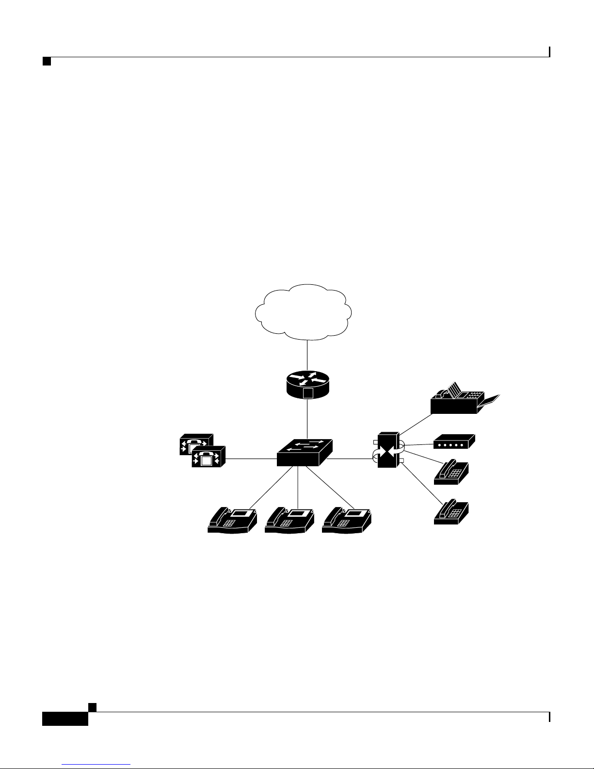
The Cisco VG248 is a high-density gateway for using analog phones, fax
machines, modems, and speakerphones within the Cisco IP telephony network
(see Figure 1-1) . The Cis co VG248 off ers 48 f ully-feat ured ana log phone lines to
be used as extensi on s t o th e C is c o CallMan ag er s y ste m i n a co mp act 19 -inc h
rack-mount chassis.
Figure 1-1 VG248 Integrated in the Cisco IP Telephony Network
PSTN
Cisco CallManager
cluster
M
M
Gateway
V
IP IP IP
IP phones
VG248
Fax
Modem
Analog
phones
63891
Cisco VG248 Analog Phone Gateway Software Configuration Guide
1-2
OL-1209-02
Page 19

Chapter 1 Overview
Understanding How the VG248 Supports Telephony Features
Understanding How the VG248 Supports Telephony
Features
Review t he fol lowing s e c t io ns to und e r stand w hich tele ph o ny fea tu r e s are
supported by the VG248 and to understand how they are implemented:
• Supported Telephony Features, page 1-3
• Understanding Voice-Mail Message Indicators, page 1-4
• Understanding Call Control Modes, page 1-4
• Understanding Caller ID Support, page 1-7
Supported Telephony Features
The VG248 supports the following features:
• Call Trans f er ( s u pervised a n d blind)
• Conference
• Call Waiting (w i th callin g p a r t y I D d is p lay)
• Hold (including switch between parties on hold)
• Call Fo rwar d A ll
• Send All Ca lls to Voi ce Mail
• Pickup
• Call Voice M ai l
• Spee d D ial (m axim um of 9 s p e e d dial s)
• Last Nu mb er Re di al
• Caller ID
To under s tan d h ow user s access an d us e th ese featur e s , see Table 1-1.
OL-1209-02
Cisco VG248 Analog Phone Gateway Software Configuration Guide
1-3
Page 20

Understanding How the VG248 Supports Telephony Features
Understanding Voice-Mail Message Indicators
The VG248 can receive message-waiting indicator (MWI) information from
Cisco CallM an ag er an d s en d it to an al og p h on es. The VG2 4 8 sen ds MWI
messages using any of the following methods:
• Playing stutter dial tone when a user picks up the phone
• Illumi nating th e MW I lamp on th e ph o ne
• Using caller ID m e ch anism to se n d in f orm ation to t he L C D sc re e n on the
phone
Yo u can enabl e or disable any of these opti ons. See th e “Choosing Message
Waiting Indicator Type” section on page 3-11 for deta ils .
Understanding Call Control Modes
Chapter 1 Overview
The VG248 supports different call control modes, which indicate how users
access an d use t he s up por ted tele ph o ny feat ur es. You can cho os e th e call con tr o l
mode appropriate to the specific needs of your users and the abilities of your
analog devices. The supported call control modes include:
• Basic
• Standard
• Feature
T o und erst and t he dif fe re nce s amon g th e thre e mo des, k e ep in mind t he fol l o wing
tips:
• The three modes differ in how they support transfer and conference.
• All modes support call waiting, and you can disable it on a per port basis
using Cisco CallManager.
• All mo de s su pp o rt feat ur e co de s f or s p eed d ia l, re di al, call for wa rd an d
pickup, and you can define or disable them on a per device basis.
• Users can access features using the hook flash, 0-9, *, or # buttons, depending
on how you have configured the feature codes.
• You cannot use a double flash hook.
See the “Choosing the Call Control Mode” section on page 3-4 for details about
setting the call control mode on the VG248.
Cisco VG248 Analog Phone Gateway Software Configuration Guide
1-4
OL-1209-02
Page 21

Chapter 1 Overview
Basic
Standard
Understanding How the VG248 Supports Telephony Features
This m od e prov id es t he mos t b asic ph on e in ter fa ce with no cal l t r an s fe r or
conferen ce f eat ures . B as ic mo de m i ght work b est f or f ax m ac hi ne s o r mo de m s.
See Table 1-1 for details about how the telephony features are accessed in basic
mode.
Standard is the default telephony mode, and it provides standard Bellcore
features, s uc h as u sed i n N o r th A m eri ca.
Users use the flash button or hook flash to transfer, conference and hold calls,
with t he f ollowin g re qu ir ements :
• You cannot use a double hook flash to end a call.
Feature
• When putting calls on hold, the first call can be e ither incoming or outgoing.
• When tran sferring a c all or establishing c o nferences, the second call must be
outgoing.
Users al so us e f eat ure code s to ac tivate ot he r features i n stan d ar d mod e. See
Table 1-1 for details about how the telephony features are accessed in standard
mode.
For simple call s , th e fe atu r e mode i s indist in guishabl e f r om th e s t an da rd m od e.
While on calls, users use the flash button or hook flash to get a second dial tone
to dial a secon d pa rt y. However, users then mu s t en ter feature co d e s t o t r an sfe r
the call o r establish a confer en ce .
When usi ng feat ure m o de wi th tw o ca lls es tabl is hed, t he ho ok flas h cyc les ar oun d
four states:
1. First call connect ed
2. Feature code to n e
3. Second call conn ected
4. Feature code to n e
OL-1209-02
Cisco VG248 Analog Phone Gateway Software Configuration Guide
1-5
Page 22

Understanding How the VG248 Supports Telephony Features
These di fferen t s tat es enable y ou to keep both calls active and s w it ch b etw e en
them. Thus, unlike Standard mode you can keep both calls active for as long as
you want and freely switch between them.
T o transfer or conference, you need to enter the relevant feature code at one of the
feature t o nes (w h ic h ar e si m il ar to d ial tones exce pt y ou can only enter f eat ur e
codes r ath er t ha n be in g ab le to d ial a d i re cto ry numb er).
See Table 1-1 for details about how the telephony features are accessed in feature
mode
Table 1-1 Overview of Default Feature Access in Call Control Modes
Basic Standard Feature
SpeedDial SpeedDial SpeedDial
*1 *2 *1 *2 *1 *2
Chapter 1 Overview
*3 *4 *3 *4 *3 *4
*5 *6 *5 *6 *5 *6
*7 *8 *7 *8 *7 *8
*9 *9 *9
Call Voice Mail Call Voice Mail Call Voice Mail
*0 *0 *0
Last Number Redial Last Number Redial Last Number Redial
*# *# *#
Forward All to Voicemail Forward All to Voicemail Forward All to Voicemail
**0 **0 **0
Forward All
1
Forward All
1
Forward All
1
**1 number **1 number **1 number
Disable Forward All Disable Forward All Disable Forward All
**2 **2 **2
Pickup Pickup Pickup
**3 **3 **3
Cisco VG248 Analog Phone Gateway Software Configuration Guide
1-6
OL-1209-02
Page 23

Chapter 1 Overview
Understanding How the VG248 Supports Telephony Features
Table 1-1 Overview of Default Feature Access in Call Control Modes (continued)
Basic Standard Feature
Call Waiting Call Waiting Call Waiting
Hook f lash to a n s w er
and switch between
Hook f la s h to an sw er an d sw it ch
betwe en calls.
Hook flash to answer and switch
betwe e n cal ls.
calls .
Blind Transfer Blind Transfer
Call 1, hook flash, call 2, hang up. Call 1, hook flash, #2, call 2, hang up
Supervised Transfer Supervised Transfer
Call 1, hook flash, call 2, wait for
call 2 to be a nsw e r e d, hang u p
Conference Conference
Call 1, hook flash, call 2, hook
Call 1, hook flash, call 2, wait for call 2
to be answered, hook flash, #2
Call 1, ho ok f las h, c all 2, hook f la sh, #3
flash
Hang up Last Call
Call 1, ho ok f las h, c all 2, hook f la sh, #1
Hold
Call 1, ho o k fla s h, call 2; hoo k fl a sh to
toggle
1. When forward all is activated, users hear a distinctive dial tone to indicate that all incoming calls are currently being
forwar de d to a differ en t dir ectory num be r .
Understanding Caller ID Support
If you have activated caller ID on Cisco CallManager, the VG248 can collect that
informat io n and pa ss it on to an alog ph on es. You can d isable ca ll er I D on a per
port basis. This enables you to support caller ID on some analog phones and not
on others (see the “Enabling Caller ID” section on page 3-11 for details).
The VG248 supports the following caller ID standards:
• Bellco re G R- 3 0- CORE—North Am er ica
• ETS 300 648 and ETS 300 659-1—Europe (excluding the United Kingdom)
• British Telecom SIN227 and SIN 242—United Kingdom
OL-1209-02
Cisco VG248 Analog Phone Gateway Software Configuration Guide
1-7
Page 24

Supported Analog Devices
When a call ar r ives, th e VG 2 48 s en d s th e fo ll owing i nf o rm ati on :
• Time and date in form atio n
• Calling number up to 18 digits when available, otherwise the reason why
number i s u navaila bl e
• Callin g n ame up to 2 0 ch ar act er s w h en availab le
Supported Analog Devices
The VG248 has a maximum ringer equivalency number (REN) load of three (3)
analog devices per line (using a shared directory number), and only two of these
devices can be off-hook at any one time.
You should use analog devices designed to work in the country in which you are
using the VG248. For example, if you are using the VG248 in the United
Kingdom, you should use analog devices designed for use in that country.
Chapter 1 Overview
These s ections pr ovide an over view of the types of analog devices s up p or t e d by
the VG248:
Analog Phones
The V G248 s upp orts anal og phon e s and the st an dard t ele pho n y fea tur es a v ail a ble
on them .
• Analog Phones, page 1-8
• Speakerphones, page 1-9
• Private Line Automatic Ringdown Phones, page 1-9
• Fax Machines, page 1-9
• Modems, page 1-9
Cisco VG248 Analog Phone Gateway Software Configuration Guide
1-8
OL-1209-02
Page 25

Chapter 1 Overview
Speakerphones
The VG248 pe rforms line ec ho cancel lat ion, bu t it does not perfor m acoust ic echo
cancell ati on . S p ea ker p hones wi th bui lt -in ech o cance ll ati on su ch as the
Polycom-brand phones should work fine. However the voice quality might be
unsatisfactory when using a speakerphone that does not perform acoustic echo
cancell ati on i tself.
Private Line Automatic Ringdown Phones
A telephon e conf igur ed as a Pri va te Line Auto matic Rin gdo wn (PLAR) telepho ne
dials a pre-configured number when it goes off-hook. You cannot use PLAR
phones to dial any other numbers. Telephones in hotel lobbies and airports are
often configured in this way.
Supported Analog Devices
Fax Machines
Modems
Cisco CallManager release 3.0 and later can be configured to support the PLAR
phone fe atu re for a n IP pho ne or for an a nalo g tel ep hone c onnec ted to t he VG2 48.
The V G248 supp orts fax m achines in pass-through and Cisco fax relay modes. In
fax pass-through mode, the gateways do not distinguish a fax call from a voice
call. Cisco fax relay offers a more reliable way of transporting the fax data in
order to increase the data rate. However, the terminating gateway must also
support Cisco fax relay. If necessary, you can disable Cisco fax relay (see the
“Disabling Cisco Fax Relay” section on page 3-3 for details) .
The VG248 supports modems in pass-through mode.
OL-1209-02
Cisco VG248 Analog Phone Gateway Software Configuration Guide
1-9
Page 26

Supported Protocols
Supported Protocols
The VG248 supports several industry-standard and Cisco networking protocols
required for voice communication over an IP network. Additionally, the VG248
supports protocols required for remote network management.
These sections provide an overview of the protocols supported by the VG248:
• Data and Voice Protocols, page 1-10
• Network Management Protocols, page 1-10
Data and Voice Protocols
The VG248 supports the following data and voice communication protocols.
Chapter 1 Overview
• Internet Protocol (IP)—addresses and sends packets across the network.
• Inte r net Gr ou p Manage m e nt Pr ot ocol ( IG M P ) — u s ed to report multicast
group memberships
• Trivial File Transfer Protocol (TFTP)—allows you to transfer files over the
network.
• Hyper Text Trans f e r P r ot ocol ( H T TP ) — d e fi nes how m essages a re for matte d
and trans mitte d, and what acti ons Web servers and browsers s hould take in
respons e to va ri ous c omma n ds .
• File Transfer Protocol (FTP)—allows you to transfer files over the network.
• Dynam ic Hos t Con figurat ion P roto col (DH CP )—d ynam ica lly allo ca tes and
assi gn s an IP a ddres s to networ k devic es .
• Real-Time Transport Protocol (RTP)—enables transporting of real-time data,
such as inter a ctive voic e a n d v ideo over data networ ks.
• Skinny Client Control Protocol (SCCP)—enables communication between
the VG24 8 an d Ci sc o CallM an ag er.
Network Management Protocols
The VG248 supports Simple Network Management Protocol (SNMP) and
implements several industry-standard Management Information Bases (MIBs).
Cisco VG248 Analog Phone Gateway Software Configuration Guide
1-10
OL-1209-02
Page 27

Chapter 1 Overview
Understanding SNMP Support
The VG248 supports SNMP versions 1 and 2, enabling you to perform the
following commands:
• Get—Retrieve a specific node’s value.
• GetNext—Retrieve the first value present in the ordered tree whose node
succee ds th e o n e s p ec ifie d.
• GetBulk—Retrieve bounded number of values whose nodes succeed, in the
numer ica l orde rin g, the on e spe cified. GetBulk is a vailabl e only in SNMP v2.
• Set—S et a s pe cifi c valu e.
Understanding Trap Support
The VG248 generates the following general traps, as defined in RFC 1157:
Supported Protocols
• Cold st ar t—whe n the VG24 8 star ts up a nd o bt ai ns an IP ad dr ess
• Warm start—when the VG248 changes IP addresses
• Authe nt ic ation fa il ur e— w hen an invalid commu n ity string i s u s ed
Yo u mu st h ave se t at lea s t on e networ k m anage ment s tation in or der f or the
VG248 to generate traps. See the “Configuring Trap Settings” section on
page 2-1 4 for details.
Understanding Supported MIBs
The VG248 supports the following MIBs.
RFC 1213
RFC 1213 is the basi c MIB 2 specif i cat io n whic h indi cat es th e sta te of embe dd ed
interfaces and s tat ist ics fo r n etw o rk p r ot oc ol s .
The VG248 supports RFC 1213 with the following caveats:
• ifAdm in Stat u s f or t he Ethernet inte rface cann ot b e w ritten, an d i t i s fixe d at
“up”.
• ifSpeci ficfo r a ll in terface s r etu r ns as “ 0, 0” .
• atTable c an no t be w r itt en .
OL-1209-02
Cisco VG248 Analog Phone Gateway Software Configuration Guide
1-11
Page 28

Supported Protocols
Chapter 1 Overview
• No “ip***” values can be written.
• You cannot write to “tcpConnState” for an active TCP connection.
• The VG248 does not implement the External Gateway Protocol (EGP).
Interface MIB
This MIB is defin ed in RFC 1573 and e xtends the range of information availabl e
about a device's interfaces from that provided by the ifTable in RFC 1213. The
VG248 implements this MIB for its Ethernet interface and the 48 FXS interfaces.
However, the octet or packet count values are not available for the FXS interfaces
becaus e th ey a re not applic ab le to these inte rface typ es .
RMON
The VG248 implements the Ethernet Statistics group in Remote Monitoring
(RMON ), w it h th e ex cep ti on o f “Et he r St at sS tat us. ” This is fixed at “val id ” a nd
cannot be written.
Cisco CDP MIB
Cisco D is covery P ro t o co l (CD P ) is a m e thod t hat Cis co devices us e to advert is e
their presence and to discover information about other nearby devices. The
VG248 supports CDP and implements this MIB. You can enable or disable CDP
on the VG2 48 . S ee t h e “Ena bl in g CDP” section on pag e 2-10 for de tails .
Cisco Process MIB
This MIB describes the processes currently running on the device. However,
because the VG2 4 8 ru n s th r ead s, r ather than p rocesses, t he M I B i s impleme nt ed
with t he f ol low in g caveats:
• The amount of memory allocated is not recorded on a per-thread basis.
Therefore, cp m Pr oc Ex tM em Al lo ca ted a nd cp m Pr o cEx tMemFreed ar e
returned as 0.
• All threads run at the same priority. Therefore, every process
cpmProcExtPriority are returned as “normal.”
• It is not possi bl e t o cha ng e a proces s’s prior it y, so attempts to w r it e
“cpmPro cEx tPr io r it y” ar e un s uc cessf u l.
Cisco VG248 Analog Phone Gateway Software Configuration Guide
1-12
OL-1209-02
Page 29

Chapter 1 Overview
Supported Protocols
Cisco Memory Pool MIB
This MI B allo ws de tail ed info rmat ion to be retri e ved f or all m emory po ols p resen t
within a Cis co device. The VG 248 im pleme nt s th is MI B, b ut beca use al l dyn amic
memory ma nage ment use s a sin gle he ap, the re sult i ng t able has one ro w, which is
returned as “Processor”.
Cisco EnvMon MIB
“EnvMon” re fe r s to t he on - bo ar d enviro nm en tal mon ito r o n t h e VG2 4 8 th at
monito rs th e internal voltag e, power su pp ly, tem p er atu r e, a nd f an setting s.
The VG248 ro utin ely measur es the se val ues record ing th e informat ion in the row s
withi n th e different tables:
• ciscoEnvMonVoltageStatusTable—records voltage and power supply
readings
• ciscoEnvMonFanStatusTable—records fan status readings
• ciscoEnvMon Tempera tu reS tat usTable—re co rd s t em p er at ure settin gs
You can use this MIB to access these recorded values. Also, if the VG248 detects
readings beyond the acceptable limits, the device generates warning messages.
See the “Troub lesh oo ting H a r d ware Er r ors” s ection on page 6 - 1 fo r deta ils.
Cisco Voice Interface MIB
This C is co pr o pr ietary MIB (CISCO-VOICE-IF-MIB.my) allows access to
voice inter fa ce pa ra met er s su ch as g ai n val ue s an d ec ho ca nc ell ation stat us. The
VG248 implementation of this MIB provides read access only. You can configure
the gain values using the VG248 interface (see the “Se tti n g t h e O u tput G ai n”
section on page 3-13 and the “Setting the Input Gain” section on page 3-14 for
detai ls ) .
Cisco Analog Voice Interface MIB
This C is co pr o pr ietary MIB (CISCO-VOICE-ANALOG-IF-MIB.my) allows
access to in terface pa ram eter s related to the ana log po rts. The se param ete rs
include h ar d wa re iss u es s uc h as el ect r ica l imped an ce val ue an d r ing fr eq u en cy
and user factors such as whether an attach ed handset is currently on- or off-hook.
The electrical impedance value and ring frequency is determined by the country
code you set in the VG248 (see “Identifying the Country Code for VG248”
section on page 3-6 for details). You can modify the hook-flash timer using the
VG248 int er face ( s ee “Changing the Hook Flash Timer for Analog Phones”
section on page 3-7).
OL-1209-02
Cisco VG248 Analog Phone Gateway Software Configuration Guide
1-13
Page 30

Supported Protocols
Chapter 1 Overview
Cisco VG248 Analog Phone Gateway Software Configuration Guide
1-14
OL-1209-02
Page 31

CHAPTER
2
Getting Started with the VG248
Before you can configure the telephony features on the VG248 to interact with the
analog phones, you must first configure the basic network, SNMP, and password
settings. These settings enable the VG248 to connect to the IP network and help
you manage the device.
These sections provide details about configuring these settings on the VG248:
• Accessing Configuration Options, page 2-1
• Restarting the VG248, page 2-4
• Configuring Network Settings, page 2-4
• Configuring Passwords, page 2-11
• Configuring SNMP Settings, page 2-12
Accessing Configuration Options
You can access the VG248 configuration options, after the device has started up,
using a console terminal connected to the RJ-45 console port or through a Telnet
session.
Cisco VG248 Analog Phone Gateway Software Configuration Guide
OL-1209-02
2-1
Page 32

Accessing Configuration Options
Using the Console Port
You might want to use the console port to connect to the VG248 when you
initial ly i ns t all th e device. Th is e nables y o u to obse rve th e i nitial startup
procedure and manually assign an IP address and host name if you are not using
DHCP.
To access the VG248 through the console RJ-45 port, perform these steps.
Task Description
Chapter 2 Getting Started with the VG248
Step 1
Step 2
Step 3
Step 4
Connec t t h e co n sol e t er m in al t o
the console port.
At the prompt, enter the password.
The VG248 does not have a
default password. If no password
has been co n fig ured , t h e m a in
menu displays.
Choose the necessary options to
complete your desired tasks.
When finished, exit the session. —
Using Telnet
See th e Cisco VG248 Analog Phone Gateway Hardware
Installation Guide.
<password>
Choose th e d es i red option f r om th e men us.
To access the VG248 through a Telnet session, you must know its IP address or
host name. By default, the device uses DHCP. If you want to assign a specific IP
address or host name, you must first configure the network settings using the
console port before connecting through a Telnet session.
To acces s t he VG248 f r om a r emote h o s t with Telnet, pe r for m th ese steps :
Cisco VG248 Analog Phone Gateway Software Configuration Guide
2-2
OL-1209-02
Page 33

Chapter 2 Getting Started with the VG248
Task Co mm an d
Accessing Configuration Options
Step 1
From the remote host, enter the
telnet com mand an d th e hos t nam e
or IP address of the VG248 that
you want to access.
Step 2
At the pr ompt, enter the passwo rd,
if you have configured one.
The VG248 does not have a
default password. If no password
has been co n fig ured , t h e m a in
menu displays.
Step 3
Choose the necessary options to
complete your desired tasks.
Step 4
When finish ed, exit the Telnet
session
Displaying the Main Menu
After connecting to the VG248 through the console port or a Telnet session, the
main men u ap pe ar s ( see Figure 2-1). Follow these guidelines to navigate the
menus:
telnet hostname | ip_addr
<password>
Choose th e d es i red option f r om th e men us.
—
• Use the arrow keys or numeric keypad to navigate the available options.
• Press Enter to c h oo s e an op tion.
• Press Esc to return to th e p r evio us me n u.
OL-1209-02
Cisco VG248 Analog Phone Gateway Software Configuration Guide
2-3
Page 34

Restarting the VG248
Chapter 2 Getting Started with the VG248
Figure 2-1 VG248 Main Menu
Restarting the VG248
Certain configuration changes to the VG248 do not take effect until you restart
the device. To restart the VG248, perform these steps:
Step 1 From the main menu, choose Configure.
Step 2 Choose Restart.
Configuring Network Settings
Yo u mu st config ur e th e n etwor k sett in gs on the VG 248 t o c o nn e ct it to the I P
netwo rk. After conf iguri ng any ne twor k setting s, you mu st rest art th e VG248. See
the “Restarting the VG248” section on page 2-4.
63311
Cisco VG248 Analog Phone Gateway Software Configuration Guide
2-4
OL-1209-02
Page 35

Chapter 2 Getting Started with the VG248
Configuring Ethernet
The VG248 fully supports 10/100 Mbps half- and full-duplex Ethernet. If you
choos e auto -ne gotia tio n, th e VG248 a utom atic all y adjus ts to the s peed a nd du ple x
mode o f t h e sw itch t o w h ic h it is attach ed. Thi s is the d efa ul t and r ec ommen de d
setting.
Follow these steps to configure the VG248 as your network requires:
Step 1 From the main menu, choose Configure.
Step 2 Choose Network interface.
Step 3 Choose Ethernet.
Step 4 Choose the op tion t ha t matc hes the setting on t he switch to w h ich t he VG2 48 i s
connected :
Configuring Network Settings
Step 5 Restart th e V G 24 8 .
Using DHCP
• auto-neg ot iat io n
• 100Mb/s half duplex
• 100Mb/s full duplex
• 10Mb/s half duplex
• 10Mb /s f u ll du p lex
If you are using Dynamic Host Configuration Protocol (DHCP) in your network,
the VG24 8 automaticall y obta in s an I P ad dress when y ou co n ne ct it to th e
network. Alt hough the VG248 uses DHCP by default, you can disabl e DHCP and
manually assign an IP address to the VG248.
To use DHCP, perform these steps:
Step 1 From the main menu, choose Configure.
Step 2 Choose Network interface.
OL-1209-02
Cisco VG248 Analog Phone Gateway Software Configuration Guide
2-5
Page 36

Configuring Network Settings
Step 3 Choose Use DHCP.
Step 4 Press Enter to to g gl e b etween yes (use DHCP) and no (do not use DHCP).
If you use DHCP, you can only modify the host name; you cannot modify the
othe r ne tw ork se t tin gs. S e e t he “Setting the H ost N ame” s ect io n on p ag e 2 - 7 fo r
detai ls .
If yo u do no t u se D HCP, you mus t ent e r the addi ti on al ne t wor k se tti ngs. Se e th ese
sections for details:
• Setting the Host Name, page 2-7
• Setting the IP Address, page 2-7
• Setting the Subnet Mask, page 2-8
• Setting the Default Router, page 2-8
Chapter 2 Getting Started with the VG248
• Setting the DNS Server, page 2-9
• Setting the Domain Name, page 2-9
Renewing IP Address from DHCP
You might ne ed to re ne w t he IP ad dres s a utom ati cal ly as si gned t o the V G248 . Fo r
exa mple, i f you have changed th e ph ysi cal l oca ti on of t he V G24 8 f rom one su bne t
to another or if you need assistance troubleshooting a connectivity problem.
To renew an I P add re s s ass i gn ed by D H C P, foll ow the s e st ep s :
Step 1 From the main menu, choose Configure.
Step 2 Choose Network interface.
Step 3 Choose Renew DHCP.
Cisco VG248 Analog Phone Gateway Software Configuration Guide
2-6
OL-1209-02
Page 37

Chapter 2 Getting Started with the VG248
Setting the Host Name
The host name identifies each VG248 on your TCP/IP network, enabling you to
access t he d evice u s in g th is n ame rat he r t h an th e I P a dd r ess .
By def au lt, th is valu e i s set to be t he s ame as the devic e n ame regi ster ed i n th e
Cisco CallM an ag er d ata ba se . T hi s d evice n am e is a u ni qu e ch ar act er str in g
gener ated base d on the MAC address for the VG248 (s ee the “Adding the VG24 8
to Cisco CallManager” section on page 4-2 for details ). Ho wev er , you can use th is
setting to modify the host name.
To chan ge th e h o st n a m e, p e rf or m these s teps :
Step 1 From the main menu, choose Configure.
Step 2 Choose Network interface.
Configuring Network Settings
Step 3 Choose Host name.
Step 4 Enter the host name to be used by the VG248.
Step 5 Restart th e V G 24 8 .
Setting the IP Address
The IP address identifies each VG248 on your TCP/IP network. You must enter
the IP address if you are not using DHCP. The VG248 automatically obtains an
IP ad dress if y ou are usin g D H C P.
To assign an I P ad d res s, p er f orm th ese steps:
Step 1 From the main menu, choose Configure.
Step 2 Choose Network interface.
Step 3 Choose IP address.
Step 4 Enter the IP address to be used by the VG248.
Step 5 Restart th e V G 24 8 .
OL-1209-02
Cisco VG248 Analog Phone Gateway Software Configuration Guide
2-7
Page 38

Configuring Network Settings
Setting the Subnet Mask
You must enter the subnet mask if you are not using DHCP. The VG248
automatically ob ta in s a s ub n et mask if y o u ar e u s in g D H CP.
To set the subnet mask, perform t hese st eps:
Step 1 From the main menu, choose Configure.
Step 2 Choose Network interface.
Step 3 Choose Subnet mask.
Step 4 Enter the subnet ma sk.
Step 5 Restart th e V G 24 8 .
Chapter 2 Getting Started with the VG248
Setting the Default Router
You must enter the default router if you are not using DHCP. The VG248
automa t ic ally ob tains a def a u lt r ou te r if y ou ar e using D H C P.
To set th e d ef a u lt ro u ter, pe r fo r m th es e s te ps:
Step 1 From the main menu, choose Configure.
Step 2 Choose Network interface.
Step 3 Choose Default router.
Step 4 Enter the IP address of the default router.
Step 5 Restart th e V G 24 8 .
Cisco VG248 Analog Phone Gateway Software Configuration Guide
2-8
OL-1209-02
Page 39

Chapter 2 Getting Started with the VG248
Setting the DNS Server
Domain Name System (DNS) allows users to specify remote computers by host
names. The VG248 uses D NS to r esolve the host name o f TFT P servers a nd
Cisco CallM an ag er sy stems whe n th e s y ste m i s co n figur ed to u se names ra t h er
than IP addresses.
To set th e D NS server, perfor m t h es e st ep s :
Step 1 From the main menu, choose Configure.
Step 2 Choose Network interface.
Step 3 Choose DNS server.
Step 4 Enter the IP address of the DNS server.
Step 5 Restart th e V G 24 8 .
Configuring Network Settings
Tips You can e nt er a secondar y D N S s er ver by c ho o sin g Network
interfa ce > DNS server 2 and en te ri ng t he IP ad dres s.
Setting the Domain Name
The dom ai n n ame is th e name o f th e Do main Nam e S y stem (D NS) d o mai n in
which th e VG248 is locat ed .
To set the domai n name , perfo rm these step s:
Step 1 From the main menu, choose Configure.
Step 2 Choose Network interface.
Step 3 Choose Domain na me .
Step 4 Enter t he d omain n a me.
Step 5 Restart th e V G 24 8 .
OL-1209-02
Cisco VG248 Analog Phone Gateway Software Configuration Guide
2-9
Page 40

Configuring Network Settings
Enabling CDP
Step 1 From the main menu, choose Configure.
Step 2 Choose Network interface.
Step 3 Choose CDP.
Step 4 Press Enter to to g gl e b etween enabled and disabled.
Chapter 2 Getting Started with the VG248
The VG2 48 ca n adve rt ise its elf to ot her ne two rk devi ces usi ng Cis co Dis cove ry
Protocol (CDP). Many network management applications require that CDP is
enabled.
To enab le CD P, per fo rm t he se s t ep s:
Setting DSCP Quality of Service Values
Differentiated Services Code Point (DSCP) is an IETF standard that uses 6 bits in the
IPv4 header's ToS (Type of Service) field to specify the class of service for each
packet. This enables you to apply differentiated grades of service to different packet
types.
You can modify the assigned DSCP Quality of S ervice (QoS) value for c ertain types
of traffic. This enables you to giv e priority to media traffic over control traf fic.
To enab le m odi fy t he D SCP Q o S val ue s , p erfo r m t he s e st ep s :
Step 1 From the main menu, choose Configure.
Step 2 Choose Network interface.
Step 3 Choose Set DSCP QoS values.
Step 4 Choos e one of the f ol lowing op tions :
• Medi a tr affic —RTP packets carrying voice, fax, and modem calls
• Control t r a ffi c—SCCP data packets carrying telephony control data
• All othe r tra ffic—such as FTP, HTTP, SNMP, and so on
Cisco VG248 Analog Phone Gateway Software Configuration Guide
2-10
OL-1209-02
Page 41

Chapter 2 Getting Started with the VG248
Step 5 Enter t he n ew valu e fo r M e d i a traffic or Control traffic from 0 to 63, using
decima l format .
By default, Media traffic is set to 46, and Control traffic is set t o 2 6. You canno t
change th e valu e f o r All oth e r traffic; it is set to 0.
Configuring Passwords
The VG248 ships without a set or enabled password. You should enable
passwords to prevent unauthorized access to and control of the VG248. The
VG248 does not support or use user names.
Once you set a password, however, the VG248 requires that you use it, whether
you are ac ces si ng th e d evic e u sin g t he co nso le po rt, t eln et , H TTP, or FTP. W h en
using the HTTP, you are required to enter the login password if one is set; you
cannot modify any settings when accessing the VG248 using HTTP. When
accessing the VG248 using FTP, the FTP server adopts the highest level of
securit y cu rren tl y s et. For exa m pl e, if y ou h ave s et b ot h a l og in an d enable
password, you must use the enable password to use FTP.
Configuring Passwords
Caution By default, the VG248 does not have an assigned password. To
avoid unauthorized access, assign passwords to this device.
Configuring the Login Password
The login password enables you or other users to view the current status of the
VG248. To configure the login password, perform these steps:
Step 1 From the main menu, choose Configure.
Step 2 Choose Passwords.
Step 3 Choose Login password.
Step 4 Enter the new password.
Cisco VG248 Analog Phone Gateway Software Configuration Guide
OL-1209-02
2-11
Page 42

Configuring SNMP Settings
Configuring the Enable Password
The enab le pass wo rd a llo ws yo u to vie w c urr en t se ttin gs and mak e chang es t o th e
VG248. Once set, you must use the enable password to make changes to the
VG248.
To configu re the enab le pass wor d, pe rfo rm th es e s te ps:
Step 1 From the main menu, choose Configure.
Step 2 Choose Passwords.
Step 3 Choose Enable password.
Step 4 Enter the new password.
Chapter 2 Getting Started with the VG248
Configuring SNMP Settings
The VG248 supports Simple Network Management Protocol (SNMP) by
supporting standard MIBs. Modify the SNMP settings as appropriate for your
network management needs. You need to configure the SNMP settings if you
want to ma nage th e VG24 8 r em o tely.
Setting Community Strings
The community string settings enable network management systems to access the
VG248 for remote management.
You can configure a read-only password, which restricts access to the device,
allowing users to view information but not to make changes. You can also
configure a re ad -wr it e co mm u ni ty str ing, w h ich all ows u ser s to mak e ch an ge s to
the device remotely.
By def au lt, the r ea d- o nl y comm u n ity s t ri ng i s set to
read-only access. If you do not set these community strings on the VG248, you
cannot manage the device remotely using the Simple Network Management
Prot ocol ( S NMP) .
public, which provides
Cisco VG248 Analog Phone Gateway Software Configuration Guide
2-12
OL-1209-02
Page 43

Chapter 2 Getting Started with the VG248
To set the community strings, p erform the se steps:
Step 1 From the main menu, choose Configure.
Step 2 Choose SNMP.
Step 3 To set the read- onl y co mmu ni ty st ring , cho ose Read-only community string.
Step 4 To set th e r ead-wr ite commu n it y st r in g, choo se R ea d -wri t e co m mu nity stri n g.
Step 5 Enter the community string value.
Configuring Contact Information
You can enter the contact name of the person responsible for the VG248 and the
location of the VG248 on your campus.
Configuring SNMP Settings
Configuring Contact Name
The contact name on the VG248 corresponds to the sysContact variable defined
in RFC 1213.
To add a contact name indicating the person responsible for the VG248, perform
these steps:
Step 1 From the main menu, choose Configure.
Step 2 Choose SNMP.
Step 3 Choose Contact name.
Step 4 Enter the name of the person responsible for the VG248.
OL-1209-02
Cisco VG248 Analog Phone Gateway Software Configuration Guide
2-13
Page 44

Configuring SNMP Settings
Configuring System Name
The system name on the VG248 corresponds to the sysName variable defined in
RFC 1213.
To specify the system name of the VG248 to the network management system
perform these steps:
Step 1 From the main menu, choose Configure.
Step 2 Choose SNMP.
Step 3 Choose System name.
Step 4 Enter the system name of the VG248.
Chapter 2 Getting Started with the VG248
Configuring Location
The location on the VG248 corresponds to the sysLocation variable defined in
RFC 1213.
To add the location of the VG248 in your network or on your site, perform these
steps:
Step 1 From the main menu, choose Configure.
Step 2 Choose SNMP.
Step 3 Choose Location.
Step 4 Enter t he locati on o f th e V G 24 8.
Configuring Trap Settings
You can configure the VG248 to notify up to four network management systems
when certain significant system events occur. You can also specify the IP address
for the ne tw or k man a g ement sy stem tha t i s ac tin g as a tr a p r ec eiver. See th e
“Understanding Trap Support” section on page 1-11 for information about
supported trap types.
Cisco VG248 Analog Phone Gateway Software Configuration Guide
2-14
OL-1209-02
Page 45

Chapter 2 Getting Started with the VG248
Enabling Authentication Traps
To enab le au th en ticatio n t rap s , p er for m these steps:
Step 1 From the main menu, choose Configure.
Step 2 Choose SNMP.
Step 3 Choose Ge nera te au th entica t i o n traps.
Step 4 Press Enter to to g gl e b etween yes and no.
Configuring Trap Receiver Stations
To set up to fou r t r ap re ceiver s t ati on s, perfo rm th es e s te ps:
Configuring SNMP Settings
Step 1 From the main menu, choose Configure.
Step 2 Choose SNMP.
Step 3 Choose Trap receive r statio ns.
Step 4 Enter the IP address or host name of the network management system used to
receive the trap s .
OL-1209-02
Cisco VG248 Analog Phone Gateway Software Configuration Guide
2-15
Page 46

Configuring SNMP Settings
Chapter 2 Getting Started with the VG248
Cisco VG248 Analog Phone Gateway Software Configuration Guide
2-16
OL-1209-02
Page 47

CHAPTER
3
Configuring the Telephony Settings on
the VG248
The telephony settings on the VG248 determine the functionality of the analog
phones connected to it. However, before configuring these settings, ensure that
you have completed the basic network configuration described in Chapter 2,
“Getti ng S t ar ted w it h th e V G 248.”
After ver i fyin g connec tivity to the n etw ork , r eview th ese sectio n s to cu st omize
the telephony settings:
• Identifyi ng t he Ci sco Cal lM an ag er TFTP Ser ver, page 3-2
OL-1209-02
• Changin g th e Cisco CallMan ag er D evi ce Na m e, pa ge 3-2
• Disabling Cisco Fax Relay, page 3-3
• Reverting to Previous Configuration, page 3-3
• Choosing the Call Control Mode, page 3-4
• Assigning Feature Codes, page 3-4
• Identifying the Country Code for VG248, page 3-6
• Changing the Hook Flash Timer for Analog Phones, page 3-7
• Setting the Port Enable Policy, page 3-7
• Configuring Port Parameters, page 3-9
Cisco VG248 Analog Phone Gateway Software Configuration Guide
3-1
Page 48

Chapter 3 Configuring the Telephony Settings on the VG248
Identifying the Cisco CallManager TFTP Server
Identifying the Cisco CallManager TFTP Server
The VG24 8 use s th e TFTP server to id en ti f y t h e co rr ect Ci s co CallM an ag er
system. If you are using DHCP, the VG248 attempts to obtain the TFTP server
address fro m t he D H CP s erver. Or, you can s el ect a di fferent TF TP server by
modifying this setting. If you are not using DHCP, or if your DHCP server is not
conf igured wi th a TFT P serv er addre ss, you should i dentif y the TFTP serv er usi ng
this sett ing.
To assign a TF TP server, perform t h ese st ep s :
Step 1 From the main menu, choose Configure.
Step 2 Choose Telephony.
Step 3 Choose CallManager TFTP server.
Step 4 Enter the IP address or host name of the TFTP server.
Changing the Cisco CallManager Device Name
The VG248 uses the Cisco CallManager device name when registering ports with
Cisco CallManager. The actual device name used is the value shown for this menu
option followed by the port number. By default, this is se t to “VGC ” f ollo w ed by
10 digits of the VG248's MAC address. For example, port one would use
VCGxxxxxxxxxx01 as its device name, where xxxxxxxxxx are the last 10 digits
of the MAC address.
You can change the default device name, but you must use the standard format
described in the “Using Auto-Registration” section on page 4-2.
Step 1 .From the main menu, choose Configure.
Step 2 Choose Telephony.
Step 3 Choose CallManager device name.
Step 4 Enter the new device name.
Cisco VG248 Analog Phone Gateway Software Configuration Guide
3-2
OL-1209-02
Page 49

Chapter 3 Configuring the Telephony Settings on the VG248
Disabling Cisco Fax Relay
The VG248 supports Cisco fax relay. Cisco fax relay provides a more reliable
method of transporting fax data over the IP network rather than sending the fax
information as a voi ce call. H owever, the te rm in ati ng d evic e must also sup p or t
Cisc o fax relay.
By defaul t, Cis co f ax re lay i s ena bled on th e VG248 . Howeve r, follo w thes e step s
to disable i t:
Step 1 From the main menu, choose Configure.
Step 2 Choose Telephony.
Step 3 Choose Fax re la y.
Step 4 Choos e one of the f ol l ow in g:
Disabling Cisco Fax Relay
• Enabled
• Disabled
Reverting to Previous Configuration
By def au lt, the V G 48 p o rt s identi fy t he ir co n fig ur at io n usi ng TFTP. Th is
configur ati on d et er min es th e Cisco CallM a nager sy st em t o w hi ch th es e p or ts
connec t.
If persistent TFTP problems prevent the VG248 from retrieving this
configuration, the VG248 ports can revert to their previous configuration. This
enables th e p o rt s to connect to t he C isco Cal lM an ag er sy s tem w it h wh i ch th ey
were previously registered.
By def au lt, the V G 24 8 au to m at ic a ll y rever ts to th e p r evio us co nfi gu r ati on i f th e
ports f ail t o connect via TF TP. To d is ab le th is fu n cti o nality, follow t he s e steps:
Step 1 From the main menu, choose Configure.
Step 2 Choose Telephony.
OL-1209-02
Cisco VG248 Analog Phone Gateway Software Configuration Guide
3-3
Page 50

Chapter 3 Configuring the Telephony Settings on the VG248
Choosing the Call Control Mode
Step 3 Choose Allow last good configuration.
Step 4 Choos e one of the f ol l ow in g:
• yes
• no
Choosing the Call Control Mode
The call co nt rol mode d et er min es h ow users int eract with t he ir an alo g ph o ne s to
access fe a tu re s su ch as s pe ed di al in g, cal l tr an s fer, con fer en ce, call w ai tin g , a nd
so on.
For assistance determining which call control mode best meets your needs, see the
“Understanding Call Control Modes” section on page 1-4.
Follow the s e st eps to s e t t he call co ntrol mo de:
Step 1 From the main menu, choose Configure.
Step 2 Choose Telephony.
Step 3 Choose Call co ntrol mode .
Step 4 Choos e one of the f ol l ow in g:
• Basic
• Standard
• Feature
Step 5 Restart th e V G 24 8 .
Assigning Feature Codes
Many of t h e t elephony features availa bl e i n s tand ar d an d fe atu r e mode a re
activated by feature codes, which end users indicate using the dial pad on their
telephones.
Cisco VG248 Analog Phone Gateway Software Configuration Guide
3-4
OL-1209-02
Page 51

Chapter 3 Configuring the Telephony Settings on the VG248
Yo u can c han g e t he se f eature co d es fr om thei r de fault valu es u sing the s e st ep s :
Step 1 From the main menu, choose Configure.
Step 2 Choose Telephony.
Step 3 Choose Feature codes.
Step 4 Choose th e code to co n figur e.
Step 5 Enter the setting for the code.
The defa u lt settings for th e featu re codes ar e as fol lows:
Code Default Setting Call Mode
Assigning Feature Codes
Hang up last call
Transfer
Conference
Forward all to voice mail
Call forward all
Cancel call forward
Pickup
Redial
SpeedDial Voicemail
SpeedDial 1
SpeedDial 2
SpeedDial 3
SpeedDial 4
SpeedDial 5
SpeedDial 6
1
#1 Feature
#2 Feature
#3 Feature
**0 All
**1 All
**2 All
**3 All
*# All
*0 All
*1 All
*2 All
*3 All
*4 All
*5 All
*6 All
SpeedDial 7
SpeedDial 8
SpeedDial 9
OL-1209-02
*7 All
*8 All
*9 All
Cisco VG248 Analog Phone Gateway Software Configuration Guide
3-5
Page 52

Identifying the Country Code for VG248
1. When forward all is activated, users hear a distinctive dial tone to
indicate that all incoming calls are currently being forwarded to a
different directory number.
Tip • If you set a feature code to a blank string, users cannot use that feature.
• Yo u can n ot d isab le tr an sf er o r co nf er en ce in st an da rd mo d e b ecause t ho se
features are activated by hanging up or using the hook flash, rather than by
feature c odes .
• If y ou ha v e t w o f eatu re code s a ssi gne d to t he same set ti ng , one o f the f eat ure s
does no t work .
• If one feature code setting masks ano ther, you cannot use the masked set ting
(such a s if t ra nsf er i s * an d co n fe re nc e i s **, confer en ce d oes no t wo r k).
Chapter 3 Configuring the Telephony Settings on the VG248
Identifying the Country Code for VG248
The country code identifies the country in which you are using the VG248. It
automaticall y sets co un tr y -specific se t ti ng s, s u ch as the soun d o f th e to nes, the
cadence o f th e rin g s , i mpe da nc e, hook flash ti m er, and gai n, f or ex amp le.
Follow these steps to set the country code,
Step 1 From the main menu, choose Configure.
Step 2 Choose Telephony.
Step 3 Choose Country.
Step 4 Choose the country name in which you are using the VG248.
If your country is not available, select a country that uses the same telephony
standards.
Step 5 Restart th e V G 24 8 .
Cisco VG248 Analog Phone Gateway Software Configuration Guide
3-6
OL-1209-02
Page 53

Chapter 3 Configuring the Telephony Settings on the VG248
Changing the Hook Flash Timer for Analog Phones
Changing the Hook Flash Timer for Analog Phones
The hook flash timer is the length of time before the hook flash indicates a
time-out (or call disconnect). The hook flash timer setting is based on the country
of or igin of the analog phones . When you s et the country code on the VG248, the
hook flash timer is automatically set to the default for that country.
However, you can m o d if y th is settin g, if d esired.
To change the hook flas h timer, follow thes e steps:
Step 1 From the main menu, choose Configure.
Step 2 Choose Telephony.
Step 3 Choose Hook flas h time r.
Step 4 Choose the appropriate hook flash timer value for your analog phones.
Setting the Port Enable Policy
To configure the ports on the VG248 and the features required for the analog
devices co nn ec ted t o th e p o rt s, y ou must ad d th em to th e Cisco CallM an age r
datab as e.
The port e na bl e p olicy on th e V G24 8 d et er min es w h et he r t he VG2 48 ca n en ab l e
a port an d r egist er th e ph o ne in C isco Cal lM an ag er.
Before You Begin
The po rt en ab le policy in ter ac ts w i th th e au to -r egi s tr at io n se t tin g s in
Cisco CallM an ag er. Review the f ol lowin g exp lan at io ns befor e choos in g a p ort
enable poli cy:
OL-1209-02
Cisco VG248 Analog Phone Gateway Software Configuration Guide
3-7
Page 54

Chapter 3 Configuring the Telephony Settings on the VG248
Setting the Port Enable Policy
VG248 Cisco CallManager Analog Phone Behavior Tips
auto auto-regi strat ion enab led
auto auto-regi strat ion dis abled
manual auto-regi strat ion enab led
or dis abled
1. User picks up the phone to use for
first ti m e.
2. VG24 8 attemp ts to register in
Cisco C al lManager
3. Cisco C allManag er adds p hon e t o
database.
4. User m akes cal l.
1. User picks up the phone to use for
first ti m e.
2. VG24 8 attemp ts to register in
Cisco C al lManager
3. Cisco C allManag er r ef u ses
registration.
4. If phone is not registered, user
canno t m ake cal l.
1. User picks up the phone to use for
first ti m e.
2. VG248 doe s not att empt to re gist er
with Cisc o C allM anager.
3. User cannot make call.
If the phone has
already been
manu all y adde d and
configured in
Cisco CallM an age r,
Cisco CallM an age r
recogniz es t hi s, and
the phone works.
Yo u can en ab le th e
specific p ort that is
connec ted to th is
phone. The VG248
will th en a ttemp t t o
register this port with
Cisco CallM an age r.
See the “Enablin g a
Specific Port” section
on page 3-9 fo r
detai ls .
To set th e p o rt en able p ol icy on t he VG248 , f o ll ow the s e st ep s :
Step 1 From the main menu, choose Configure.
Step 2 Choose Telephony.
Cisco VG248 Analog Phone Gateway Software Configuration Guide
3-8
OL-1209-02
Page 55

Chapter 3 Configuring the Telephony Settings on the VG248
Step 3 Choose Port e n abl e p o li cy.
Step 4 Choose one of these options:
• auto (default setting)
• manual
Configuring Port Parameters
You must con figur e the VG248 ports us ing Cisco Ca llManager. Each of the ports
are ente red in the C isco Cal lM an ag er d ata ba s e a s a “VGC” p h on e t yp e. S ee th e
“Configuring the VG248 Analog Ports” section on page 4-3 for details.
These se cti on s p rovid e d etails of th e p ar ame ter s th at yo u co nfigu re on a per por t
basis:
Configuring Port Parameters
• Enabli ng a Specifi c Po r t, p ag e 3-9
• Enabling Caller ID, page 3-11
• Choosing Message Waiting Indicator Type, page 3-11
• Enab ling D is c onnec t S u pervis ion, page 3-12
• Setting the Output Gain, page 3-13
• Setting the Input Gain, page 3-14
Althou gh t hese pr oced ures des cri be how to make change s t o i ndi v id ual p orts , yo u
can configure a range of ports to use the same settings. To do this, choose
Telephony > Port specific parameters, and then pres s R on the keyboard. Then
enter a port range (such as 1-10, or 1, 2,3) and apply cha nges to all of those ports
at once .
Enabling a Specific Port
By enabli ng a spe cifi c port on t he VG2 48, you ar e allo wing it to be re giste red wit h
Cisco CallM an ag er. When u sed in co n ju nc ti on w it h th e p o rt en ab le policy (se e
the “ S ett in g th e P o r t E na bl e P o li cy” section on p ag e 3-7), yo u ca n de t e r m i ne
whether an analog phone can simply be plugged into a port connected to the
VG248 and be ready to use.
OL-1209-02
Cisco VG248 Analog Phone Gateway Software Configuration Guide
3-9
Page 56

Chapter 3 Configuring the Telephony Settings on the VG248
Configuring Port Parameters
Before You Begin
Before ch angin g th e po rt enabl e st atus for a speci fi c po rt, re vi e w these gu id eli nes
to und er s t and how th is sett in g intera cts with t he port e nable p o licy.
Port Enable Policy Port Enable Status Explanation
auto enabled You have used this phone and registered this port in
Cisco C al lManager.
auto disabl ed You h ave eit h er man u a ll y dis ab le d t h e sp ecific port
using the Telephony > Port specific parameters
menu, or no one has attempted to use a phone
conne c te d to this por t.
This is t he defaul t s ettin g.
After s o meone att emp ts to u s e a ph o ne co n ne cted to
this port, the port enable status will change to enabled.
manual enabl ed You have ma nually en abled the specific port us ing the
Telephon y > Por t sp eci fic para meters menu. By
doing t his, y ou ar e ove rridi ng th e manual sett ing on t he
port en ab le po li cy.
When the VG 2 48 starts u p , t he por t w i ll at tempt to
register w i th C is co CallM an ag er.
manual disabled The port cannot be enabled by picking up the phone.
To use the phone, you must manually change the port
from disabled to enabled using the Te lephony > Port
specific p ar am e te r s menu.
Follow thes e st ep s to e na bl e a speci fic po rt :
Step 1 From the main menu, choose Configure.
Step 2 Choose Telephony.
Step 3 Choose Port sp e cific p a ra me te rs.
Step 4 Use the ar r ow keys t o s ele ct the p o rt to configur e an d pr ess Enter.
Cisco VG248 Analog Phone Gateway Software Configuration Guide
3-10
OL-1209-02
Page 57

Chapter 3 Configuring the Telephony Settings on the VG248
Step 5 Choose Status.
Step 6 Choose enabled or disabled.
Enabling Caller ID
You can enable caller ID on a per-port basis. This allows caller ID information to
be passed to some, all, or none of the analog phones connected to the VG248.
Enabling caller ID determines how the VG248 handles any caller ID instructions
received from Cisco CallManager. If you are not using caller ID on
Cisco CallM an ag er, then th e V G 24 8 does no t re ceive a ny cal ler i nf o rm ati on t o
pass on to the analog ports, regardless how you set the VG248.
To enab le cal ler I D f or a speci fic por t o n th e V G 24 8 , fol low th ese inst ru ct io ns:
Configuring Port Parameters
Step 1 From the main menu, choose Configure.
Step 2 Choose Telephony.
Step 3 Choose Port sp e cific p a ra me te rs.
Step 4 Use the ar r ow keys t o s ele ct the p o rt to configur e an d pr ess Enter.
Step 5 Choose Calle r I D .
Step 6 Choose from the following options:
• enabled
• not with call waiting—Caller ID di spla ys on ly if no ot her c all s are cur rent ly
active
• disabled.
Choosing Message Waiting Indicator Type
The VG248 supports several types of methods for sending MWI messages to
analog phones. Because you might have different types of analog phones
conne cte d to the V G248 , you ca n modi fy the MWI type on a per -p ort basi s. So, if
OL-1209-02
Cisco VG248 Analog Phone Gateway Software Configuration Guide
3-11
Page 58

Configuring Port Parameters
you ha v e s ome a na log pho nes th at h av e MWI lamps o n the m, you can no tify use rs
of awaitin g mes sages u s in g th e l amp . O r, you can cho o se t o pl ay a to ne when
users pick up their phones.
Keep in mind that the VG248 only sends this information to the phones if it is
received from Cisco CallManager. If Cisco CallManager is not integrated with
your voice mail system, it does not send this information to the VG248.
Step 1 From the main menu, choose Configure.
Step 2 Choose Telephony.
Step 3 Choose Port sp e cific p a ra me te rs.
Step 4 Use the ar r ow keys t o s ele ct the p o rt to configur e an d pr ess Enter.
Step 5 Choose MWI type.
Step 6 Choose from the following options:
Chapter 3 Configuring the Telephony Settings on the VG248
• Lamp —illuminates lamp on phone
• Caller ID—uses cal le r ID mechan ism to sen d M W I messages t o t h e LC D
screen on phone
• Stutter—plays tones when user picks up the phone
• Lamp + stutter—illuminates lamp and plays tone
• Caller ID + stutter—sends message to LCD screen and plays tone
• None—does not send MWI information
Enabling Disconnect Supervision
Discon nect sup er v is i on i nd icates to a n analo g devi ce that th e r emote c a ll er h as
hung up. For example, if a user calls someone with an answering machine, leaves
a messa ge, and ha ngs up , d iscon ne ct s uperv isi on i s th e ele ctr ic al s tat e tha t b riefl y
drops the lo op cu r re nt an d i ndicates to th e an sw er in g mach ine that the cal ler h as
hung up.
Cisco VG248 Analog Phone Gateway Software Configuration Guide
3-12
OL-1209-02
Page 59

Chapter 3 Configuring the Telephony Settings on the VG248
Follow these steps to enable disconnect supervision on a per port basis:
Step 1 From the main menu, choose Configure.
Step 2 Choose Telephony.
Step 3 Choose Port sp e cific p a ra me te rs.
Step 4 Use the ar r ow keys t o s ele ct the p o rt to configur e an d pr ess Enter.
Step 5 Choose Disconnect supervision.
Step 6 Choose from enabled or disabled.
Setting the Output Gain
Configuring Port Parameters
The outpu t gai n sp eci fies, in d eci be ls, th e am o u nt of gain fro m th e VG24 8 to th e
analog phone.
The country option you set on the VG248 determines the default output gain.
However, you migh t n eed t o m o di fy i t t o account f o r di fferen t cab le lengths
(longer cables might require more gain), to make the signal louder or quieter, or
to use a phone from a different country.
Follow the s e steps to modif y th e inpu t gai n. The d e fa u lt s ett in g is based on t he
country code you set (see the“Identif yi ng the Cou n t r y Co de for V G 24 8” section
on page 3-6).
Step 1 From the main menu, choose Configure.
Step 2 Choose Telephony.
Step 3 Choose Port sp e cific p a ra me te rs.
Step 4 Use the ar r ow keys t o s ele ct the p o rt to configur e an d pr ess Enter.
Step 5 Choose Output gain.
Step 6 Choose from the available options (ranging from -14dB through 0db)
OL-1209-02
Cisco VG248 Analog Phone Gateway Software Configuration Guide
3-13
Page 60

Configuring Port Parameters
Keep in mind that the value you are choosing is a delta value and does not reflect
the actu al g ain val ue. For exa mp le, if t he ba se val ue is -3 d B, yo u might cho o s e
+1dB a s th e d el ta value. Th eref or e, th e a ctual gain val ue f or t hat p ort is -2d B
overal l.
Setting the Input Gain
The input ga in s peci f ies , i n deci bel s , the amou nt of ga i n from the an alog pho ne to
the VG248.
The country option you set on the VG248 determines the default input gain.
However, you migh t n eed t o m o di fy it to accoun t fo r di fferen t cab le leng th s, to
make the signal louder or quieter, or to use a phone from a different country.
Chapter 3 Configuring the Telephony Settings on the VG248
Follow the s e steps to modif y th e inpu t gai n. The d e fa u lt s ett in g is based on t he
country code you set (see the“Identif yi ng the Cou n t r y Co de for V G 24 8” section
on page 3-6).
Step 1 From the main menu, choose Configure.
Step 2 Choose Telephony.
Step 3 Choose Port sp e cific p a ra me te rs.
Step 4 Use the ar r ow keys t o select th e p o rt to configure and pres s Enter.
Step 5 Choose Input gain.
Step 6 Choose from the available options (ranging from -6dB through + 14db)I
Keep in mind that the value you are choosing is a delta value and does not reflect
the actu al g ain val ue. For exa mp le, if t he ba se val ue is -3 d B, yo u might cho o s e
+1dB a s th e d el ta value. Th eref or e, th e a ctual gain val ue f or t hat p ort is -2d B
overal l.
Cisco VG248 Analog Phone Gateway Software Configuration Guide
3-14
OL-1209-02
Page 61

CHAPTER
4
Configuring Analog Phones Using
Cisco CallManager
The VG24 8 co nn ec ts to Ci sco Call Ma na ge r to p rovid e access fr om the a na lo g
phones to Cisco CallManager. To configure the analog phones using
Cisco CallManager, you actually configure the ports on the VG248. The changes
you make to a specific port (such as disabling call waiting or assigning speed
dials) appl y directl y to the an alog device co nnec ted to that po rt.
The following sections provide an overview of the configuration requirements for
Cisco CallM an ag er :
• Overview, page 4-1
Overview
OL-1209-02
• Adding the VG248 to Cisco CallManager, page 4-2
• Configuring the VG248 Analog Ports, page 4-3
This guide does not contain details about configuring Cisco CallManager. Refer
to the do cu mentati on and o n lin e he lp p rovided wit h Cisco CallM an ag er f or
insta lla tion an d co n fig ur at io n instr uction s.
Cisco CallM an ag er d oe s no t re co gn iz e t he VG 2 4 8 a s a singl e IP t elephony
device. Inst ead , each of th e 48 p or t s ar e i d en tifi ed as i nd ividu al d evice s, s im il ar
to IP phones.
Cisco VG248 Analog Phone Gateway Software Configuration Guide
4-1
Page 62

Chapter 4 Configuring Analog Phones Using Cisco CallManager
Adding the VG248 to Cisco CallManager
Adding the VG248 to Cisco CallManager
Yo u can a dd th e VG 2 48 p ort s to C isc o CallM an ag er automa ti cal ly o r m an ua ll y.
These sectio ns prov ide the deta ils :
• Using Auto-Registration, page 4-2
• Manually Adding the VG248, page 4-3
Using Auto-Registration
Yo u can c ho ose to h ave t he VG2 48 au t omatical ly ad d ed to C is co CallM an ag er
using auto-registration. To do this, you must
• Ver if y th at au t o- registrati on is enab le d i n Cisco CallM an ag er. Refe r to th e
docume nt ati on o r o nl in e h el p in clu d ed w it h th e C is c o CallManager
applic ati on f o r de tai ls.
• Verify that the VG248 port enable policy is set to “auto.” See the “Setting the
Port Enable Policy” section on page 3-7 for details.
When the VG248 connects to Cisco CallManager through auto-registration, each
port con n ect ed to a n an alo g devi ce reg ist er s it sel f a s a Ci sc o VGC p ho n e.
Auto-registra tion a utom ati cal ly ass ign s phone s a dire ctory nu mber. The direct or y
number assigned is the next one available in sequential order within the device
pool assi gn ed to th is ph o ne typ e i n C isco Cal lM an ag er. However, if you need to ,
you can m od ify th i s dir ect or y n umb er fo r each emu la ted p hon e (s ee th e
“Configuring the VG248 Analog Ports” section on page 4-3).
During auto-registration, the host name assigned to the VG248 is entered in the
Descrip t io n fiel d i n th e r ecord f or t he emul ated phon e in Cisco C allMan ag er. If
you do not enter a host name, the foll owing sequ ence ap plies for the device
description: VGC + the last 10 digits of the MAC address.
Additi onal ly, Cisco Call Manag er requ ir es uni qu e MA C ad dres ses for all devices ,
but all 48 ports on the VG248 share the same MAC address. Therefore,
auto-reg istr at ion in cl udes a p ro ce s s th at converts th e M AC a dd r ess es into t hi s
format:
1. T h e first tw o digits of the M AC ad dress are drop p e d .
2. T h e n u m be r is sh ifted tw o places to t he left.
Cisco VG248 Analog Phone Gateway Software Configuration Guide
4-2
OL-1209-02
Page 63

Chapter 4 Configuring Analog Phones Using Cisco CallManager
3. The two-digit port number is added to the right.
For exampl e, if th e MAC a ddr es s o n th e VG248 is
000039A44218
the MAC address registered for port 12 in Cisco CallManager is
0039A4421812
After a d ding e ach po r t , make configuration c h a nges as d e s c ribed in th e
“Configuring the VG248 Analog Ports” section on page 4-3.
Manually Adding the VG248
If you w ant to assi gn spe cif i c di rec tor y numb ers to the e mula ted IP phone s on t he
VG248 wi th out usi ng aut o-r e gis tr ati on, yo u m ust manual ly add ea ch ph one to th e
Cisco CallM an ag er d ata base. Keep in m i nd sever al im p o rt an t facts:
Configuring the VG248 Analog Ports
• To add a VG248 port to Cisco CallManager,
a. From Cisco CallManager, choose Devices > Add a New Device.
b. Choose Cisco VGC Phone from the Ph on e ty pe me nu .
c. Cl ick Ne xt.
• Each po rt must have a u ni q ue M AC addr ess . U se t he au to - reg ist ra ti on
formula (see page 4-2) to calculate the MAC address for each port.
• Use the host name or other name for the Description for each port. For eas e
of administration, use a similar name for ports configured on the same
VG248.
• Consider adding a descriptive line to the Display field, such as “Analog
phone.”
• Configure each port as described in the “Configuring the VG248 Analog
Ports” section on page 4-3.
Configuring the VG248 Analog Ports
Each port on the VG248 corresponds to an analog device in your IP telephony
networ k. To mana ge these de vi ce s us i ng Cisc o CallManager you m u s t a dd ea ch
port to th e C is c o CallM a na ge r d at ab as e . To Cisco CallM an ag er, eac h port is
recognized and handled as a phone.
OL-1209-02
Cisco VG248 Analog Phone Gateway Software Configuration Guide
4-3
Page 64

Configuring the VG248 Analog Ports
For example, if you have 48 devices connected to the VG248, you must add and
configure 4 8 po r ts to Ci s co CallM an ag er. Cisco CallM an ag er r eco g ni zes 48
separate phones connected to it.
After the se phones are added to Cisco CallM anager, treat them as you would any
other phone in your IP telephony network. You need to add directory numbers,
calling search space, and so on. Refer to the documentation and online help
included w it h Ci s co Call M an ag er for d et ail s .
If you are using any ports on the VG248 for SMDI connections, refer to the
“Conf igur ing VG 248 SMDI Port s in Cisc o CallMana ger” sectio n on page 5- 13for
detai ls .
Chapter 4 Configuring Analog Phones Using Cisco CallManager
Cisco VG248 Analog Phone Gateway Software Configuration Guide
4-4
OL-1209-02
Page 65

CHAPTER
5
Integrating Cisco CallManager with
Voice Mail Systems Using SMDI
Simplified Message Desk Interface (SMDI) defines how phone system s provide
voice mail systems with the information needed to intelligently process incoming
calls. It is an industry-s tandard signaling protocol that supplies calling and called
party identification and sets and clears Message Waiting Indicators (MWIs)
through an RS-232 serial connection.
Using SMDI and the VG248, you can integrate your existing voice mail systems
(such as Lyrix, Octel 200, Octel 250, Octel 300 and Octel 350) and legacy PBX
systems with Cisco CallManager.
OL-1209-02
These sections provide details about designing, installing, configuring, and
verify ing th is integr atio n:
• Overview, page 5-2
• Choosing a Configuration Option, page 5-4
• Connecting the SMDI Links to the VG248, page 5-12
• Configuring VG248 SMDI Ports in Cisco CallManager, page 5-13
• Config ur in g SM D I S ettings on the VG 248, page 5-19
• Verifying and Troubleshooting the SMDI Connection, page 5-28
Cisco VG248 Analog Phone Gateway Software Configuration Guide
5-1
Page 66

Overview
Overview
Chapter 5 Integrating Cisco CallManager with Voice Mail Systems Using SMDI
The VG248 generates call information in an SMDI format for all calls coming into
any of th e SM D I -e na bled p or ts. Th e V G 248 can a ls o sen d an d receive SMDI
messag es to and f rom o th er SMDI de vi ces, suc h as oth er V G248 de vi ces, a l e g ac y
PBX, or t he leg acy voice ma il sy s tem .
The VG248 provides advantages to other methods used for integrating
Cisco CallM an ag er wit h SM D I- ba s ed voice mail sy s te m s, in clu d in g:
• Reliab ili ty f or S M D I li n ks u s i ng C isco Cal lM an ager failover (s ee
Figure 5-1).
• Scalabil ity by l in ki ng V G 248 devi ces (se e Figure 5-2).
• Multiple SMDI-based voice mail systems can be used on a single cluster, by
using on e V G2 4 8 pe r voice mail sy s tem ( see Figure 5-2).
• A single voice mail system to be used by multiple clusters, by using one
VG248 per cluster (see Figure 5-3).
• A sing le voice mail s y ste m to b e s ha re d b et w een C isco Ca llMana ge r an d a
legacy PBX ( see Figure 5-4).
Table 5-1 provides an over v iew o f the task s r eq u ir ed to i m p lement t hi s
integra tio n.
Cisco VG248 Analog Phone Gateway Software Configuration Guide
5-2
OL-1209-02
Page 67

Chapter 5 Integrating Cisco CallManager with Voice Mail Systems Using SMDI
Overview
Table 5-1 SMDI Configuration Tasks
Task Description For More Information
Decide on an
integration method
Connect the SMD I
links to the VG248
Update s ervice
parameters in
Cisco C al lManager.
Choos e one of the f ollowin g m e t ho ds:
• Basic— co nnect a voi ce mail syste m t o
Cisco CallManager system via the VG248 using
SMDI ( 4 8 por t m axim u m )
• Chained— connect a voice ma i l s y s tem t o
Cisco CallManager system via multiple VG248
devices us i ng S MDI ( m or e than 48 po r t s)
• Multip lex in g—con ne c t a vo ice mail syst em to
multiple Cisco CallManager clusters or legacy
PBX systems
Use Asyn c 1 t o c on n ect to th e voice mail s y stem (any
configuration) or SMDI source (chained or
multiplexing configuration). Use Async 2 to connect
VG248 devices together and to a legacy PBX system.
Yo u shoul d ver ify that th e voic e mail s er v ice
parameters are properly configured to support the
SMDI-ba sed voi ce ma i l sy st em .
See the “Choosing a
Config uration
Option” section on
page 5-4 .
See the “Connecting
the SM DI Links to the
VG248” section on
page 5-1 2.
See the “Configuring
Voice Mail
Parame ters in
Cisco CallM an age r ”
section on page 5-13.
Add the MWI port to
Cisco C al lManager.
Add th e vo ice ma il
ports to
Cisco C al lManager.
Upda te en d-u ser
phones.
OL-1209-02
You must add a special port to Cisco CallManager that
is used to set and clea r MWI co mmand s.
You must add and configure the V G248 ports used for
voice mail to t he C isc o CallM an ager database .
Yo u shoul d up d ate the voi ce mail setting s f o r th e
end-user p ho n es t ha t ar e usi n g t he S M D I-b ased voice
mail system.
Cisco VG248 Analog Phone Gateway Software Configuration Guide
See the “Adding the
MWI Port to
Cisco CallM an age r ”
section on page 5-14.
See the “Adding and
Configuring Voice
Mail P o rt s in
Cisco CallM an age r ”
section on page 5-16.
See the “Configuring
End- U se r P h ones”
section on page 5-18.
5-3
Page 68

Chapter 5 Integrating Cisco CallManager with Voice Mail Systems Using SMDI
Choosing a Configuration Option
Table 5-1 SMDI Configuration Tasks (continued)
Task Description For More Information
Configure the local
SMDI settings on the
VG248.
Yo u must co n fig ur e th e l ocal S MD I setting s o n th e
VG248. Some of these SMDI settings must match
settings on the voice mail system or
Cisco CallManager.
Verify the status of
the SMDI
Yo u c an ch eck th e st atu s o f th e S MDI connections to
help resolve any problems.
config ur at ion.
Choosing a Configuration Option
Yo u can u se t h e VG 2 4 8 t o in teg rate SMDI- ba s ed voice mail sy s t ems w i th
Cisco CallManager in different configurations depending on your needs:
• Basic—if you need 48 or fewer voice mail ports and do not need to integrate
with m ul ti pl e C isco Cal lM an ag er c lu ster s o r a legacy PB X s ys tem.
• Chaine d— if y o u n ee d m o re th an 4 8 voice mail p or ts ; can be u sed w it h t h e
multiplexing configuration.
See the “Configuring
SMDI Settings on the
VG248” section on
page 5-1 9.
See the “Verifyin g
and Troubleshooting
the SMD I
Conne ction ” sectio n
on page 5-28.
5-4
• Multiplexing—if you need to integrate with multiple Cisco CallManager
cluster s o r wi th a lega cy PBX sy stem.
These sect ions prov ide addit ion al infor matio n abou t these met hods :
• Basic Configuration, page 5-5
• Chaine d Co nfig urat io n, page 5-6
• Multiplexing Configuration, page 5-8
Cisco VG248 Analog Phone Gateway Software Configuration Guide
OL-1209-02
Page 69

Chapter 5 Integrating Cisco CallManager with Voice Mail Systems Using SMDI
Basic Configuration
In the basic configuration (see Figure 5-1), you can use a single VG248 device to
connec t u p to 4 8 voice chan ne ls t o a vo ice m ai l system. This configuration
enables you to u se your ex is t in g voic e mail s y s tem an d integ ra te it w ith
Cisco CallM an ag er u sin g S MD I.
When usi n g t he VG2 48 in this co nfigura t i on , y o u have a m o r e f lexible fa i love r
system than when using a single Cisco CallManager server for SMDI integration.
When co nn ec ting SM D I dir ect ly to Cisc o CallM an ag er, if t ha t
Cisco C allManag er s y stem fails, th e S M D I l in k go es d own. Th e l in k can n ot
automatically be switched or transferred to another Cisco CallManager system.
However, if you are using the VG248 and the primary Cisco CallManager system
fails, the VG248 automatically switches to its backup Cisco CallManager system,
and th e S M D I li nk r e m a in s.
Choosing a Configuration Option
Configuration Tips
When configuring the VG248 using the basic configuration, refer to these tips.
Note, how ever, that th is is n o t a co m p le te list o f th e i tems y ou mu s t co nfi gu re;
these are tips specific to the basic configuration. Refer to the “Conf iguri ng SMDI
Settings on the VG248” section on page 5-19 for a description of all SMDI
configuration tasks.
• The VG248 should be set to forward MWI commands to Cisco C allManager.
See the “Forwarding MWIs to Cisco C allManager” section on page 5-24 for
detai ls .
• If the VG248 is set to forward MWI commands to Cisco CallManager, you
must se t t he MWI d ir ect ory numbe rs in Cisco CallM an ag er. See th e
“Identifying the Directory Number for Setting MWI on Cisco CallManager”
section on page 5-26 and “Identifying the Directory Number for Clearing
MWI on C isc o CallM an ag er” sectio n on p ag e 5-27.
OL-1209-02
Cisco VG248 Analog Phone Gateway Software Configuration Guide
5-5
Page 70

Choosing a Configuration Option
Figure 5-1 Basic Configuration of VG248 SMDI Integration
Chapter 5 Integrating Cisco CallManager with Voice Mail Systems Using SMDI
Legacy
voice mail
Analog
IP IP
Chained Configuration
SMDI
Cisco CallManager
M
M
IP
68461
Each VG248 system enables you to use up to 48 ports for voice mail access. If
you need more than 48 port s, you can use the chained co nfigur ation. The chained
configurati on ( see Figure 5-2) enables you to connect multiple VG248 devices
together, expanding the number of voice ports available for your voice mail
integration.The SMDI information is shared and passed between the VG248
devices via the As y nc por ts .
Configuration Tips
When using multiple VG248 syste m s, refer to these tips. Note, howev er, that th is
is not a complete list of the items you must configure; these are tips specific to the
chained configuration. Refer to the “Configuring SMDI Settings on the VG248”
section on page 5-19 for a description of all SMDI configuration tasks.
Cisco VG248 Analog Phone Gateway Software Configuration Guide
5-6
OL-1209-02
Page 71

Chapter 5 Integrating Cisco CallManager with Voice Mail Systems Using SMDI
• All VG 2 48 s y stems co n necte d to gether must be conn ected t o a single vo ice
mail system.
• Verify that you identify the first voice mail port correctly on each VG248
device. See th e “Id en ti f yi ng the Fir st Vo ic e M ail Por t N u mb er ” sectio n o n
page 5-2 1 for details.
• The first VG248 per CallManager cluster should be set to forward MWI
commands to Cisco CallManager. See the “Forwarding MWIs to
Cisco CallM an ag er ” se cti on o n pa ge 5-24 for details.
• You do not need to s et the V G248 syste ms to forward MWI co mmands alon g
the Async 2 connection unless a second cluster or a legacy voice mail system
is attach ed t o t h e en d o f th e SM D I ch ai n. For example, if y ou ar e usi ng t he
chained configuration in conjunction with the multiplexing configuration.
See the “Forwarding MWIs to Async 2” section on page 5-25.
• If a VG248 device is configured to forward MWI commands to
Cisco CallManager, you must identify the MWI directory numbers used in
Cisco CallM an ag er. See th e “ Identifying the Directory Number for Setting
MWI on C isc o CallM an ag er” sectio n on p ag e 5-26 and “Identifying the
Directo ry N u m b er f or C lea rin g M W I o n C isco CallM an ag er ” s e cti o n o n
page 5-2 7.
Choosing a Configuration Option
• All VG248 systems connected together should use the same “Message Desk
Numbe r” value. See th e “Assigning the Message Desk N umb er” se ction on
page 5-2 4 for details.
OL-1209-02
Cisco VG248 Analog Phone Gateway Software Configuration Guide
5-7
Page 72

Choosing a Configuration Option
Figure 5-2 Chained Configuration of VG248 SMDI Integration
Chapter 5 Integrating Cisco CallManager with Voice Mail Systems Using SMDI
Legacy
voice mail
Analog
VG248
SMDI SMDI
MDI passed
etween VG248s
IP IP
Multiplexing Configuration
SMDI
Cisco CallManager
M
M
IP
68460
This m eth o d en ab les yo u to s h are a sing le voi ce m ail syste m w it h mul ti pl e
Cisco CallManager system s or another PB X sy stem. Usi ng the mu ltiplexing
configuration, you can integrate SMDI with multiple PBX systems, including:
• Multipl e C isco Cal lM an ag er c lu ster s (s ee Figure 5-3)
• Legacy PBX sy stem and Ci sco Call M an ag er (see Figure 5-4)
Configuration Tips
When integrating SMDI links from more than one PBX system, refer to these tips.
Note, how ever, that th is is n o t a co m p le te list o f th e i tems y ou mu s t co nfi gu re;
these are tips specific to the multiplexing configuration. Refer to the “Configuring
SMDI Sett in gs on t he V G248 ” se cti on on page 5-19 for a descr ipti on o f all SMDI
configuration tasks.
Cisco VG248 Analog Phone Gateway Software Configuration Guide
5-8
OL-1209-02
Page 73

Chapter 5 Integrating Cisco CallManager with Voice Mail Systems Using SMDI
• If connecting to a legacy PBX, all VG248 devices should be set to forward
MWIs to Async 2. See the “Forwarding MWIs to Async 2” section on
page 5-2 5.
• At least one VG248 per cluster should be set to forward MWI commands to
Cisco CallM an ag er. See th e “ Forwar din g MWIs to Cisco C allM anag er”
section on page 5-24.
• If you ar e n o t us in g a l egacy PBX , s et th e VG 248 s y stems to f o rwar d M W I
commands along the Async 2 connection. You do not need to set this on the
VG248 system furthest away on the SMDI chain from the voice mail system.
That VG248 device should be configured to forward MWI commands to
Cisco CallM an ag er. See th e “ Forwarding MWIs to Async 2” section on
page 5-2 5.
• If the VG248 is set to forward MWI commands to Cisco CallManager, you
must se t t he MWI d ir ect ory numbe rs in Cisco CallM an ag er. See th e
“Identifying the Directory Number for Setting MWI on Cisco CallManager”
section on page 5-26 and “Identifying the Directory Number for Clearing
MWI on C isc o CallM an ag er” sectio n on p ag e 5-27.
Choosing a Configuration Option
OL-1209-02
Cisco VG248 Analog Phone Gateway Software Configuration Guide
5-9
Page 74

Chapter 5 Integrating Cisco CallManager with Voice Mail Systems Using SMDI
Choosing a Configuration Option
Figure 5-3 Multiplexing Configuration of VG248 Integration with Multiple Cisco CallManager
Clusters
Legacy
voice mail
SMDI
SMDI
passed between
Analog
SMDI
VG248-1 VG248-2
VG248 devices
Cisco CallManager
Cluster 2
Cisco CallManager
Cluster 1
Network
IP
IP
M
M
IP
IP
M
M
IP
68594
Cisco VG248 Analog Phone Gateway Software Configuration Guide
5-10
OL-1209-02
Page 75

Chapter 5 Integrating Cisco CallManager with Voice Mail Systems Using SMDI
Figure 5-4 Multiplexing Configuration of VG248 Integration with
Cisco CallManager and Legacy PBX
Legacy
voice mail
Choosing a Configuration Option
Analog
Analog
VG248
Cisco CallManager
M
M
IP IP
IP
SMDI
SMDI
V
Gateway
Legacy PBX
68459
OL-1209-02
Cisco VG248 Analog Phone Gateway Software Configuration Guide
5-11
Page 76

Chapter 5 Integrating Cisco CallManager with Voice Mail Systems Using SMDI
Connecting the SMDI Links to the VG248
Connecting the SMDI Links to the VG248
SMDI is an RS-232-based serial protocol, and the VG248 has two serial ports for
supporting SMDI connections, the Async 1 and Async 2 ports (see Figure 5-5).
Figure 5-5 VG248 SMDI Connections
VG 248
10/100
Power
Status
Console
BASE-TX
Ports 1-24
4 8 12 16 20 24
Ports 28-48
28 32 36 40 44 48
ASYNC 1 ASYNC 2
CONSOLE
A1
A2
Tx
Rx
100
Link
68462
1
3
2
1 Async 1
2 Async 2
3 LED s
Both serial ports opera te at a fixed rate and format of 9600 baud, no parity, 8 da ta
bits, one s to p bit, and no f low contr ol. Us e a s t andard RJ - 45 - to-RJ - 45 r ollover
serial cable (up to 50 feet in length) and an RJ-45-to-DB-9 adapter to connect the
VG248 to other SMDI devices using these ports:
• Async 1—the primary serial port used for connecting to the voice mail system
(any conf ig ura tio n) or SMDI s ource (cha i ned or mul ti ple x ing co nf igur at i on).
If you are u s in g a si n gl e VG2 4 8 devi ce, co nn ec t t he voi ce ma i l sy ste m ’s
SMDI po rt to the Async 1 port on the VG248. With multiple VG248 devices,
use the As ync 1 po rt t o conne ct to the pre vi ous V G248 dev ic e’s Async 2 port.
• Async 2—used for connecting multiple VG248 devices together. If there are
multiple VG248 devices in use, connect the Async 2 port of the first VG248
device (which is connected directly to the voice mail system via the Async 1
port) to the next VG248 device’s Async 1 port. Continue to connect all the
VG248 device s in the ch ai n s imi lar l y. If you ar e c on necting a legacy PBX
system to the SMDI chain, connect the Async 2 port of the last chained
VG248 device to the SMDI port of the legacy PBX.
Cisco VG248 Analog Phone Gateway Software Configuration Guide
5-12
OL-1209-02
Page 77

Chapter 5 Integrating Cisco CallManager with Voice Mail Systems Using SMDI
Configuring VG248 SMDI Ports in Cisco CallManager
Configuring VG248 SMDI Ports in Cisco CallManager
When usi n g t h e VG 2 4 8 t o in teg rate SMDI -ba s ed voice mail s y st em s w i th
Cisco CallManager, you must make changes to Cisco CallManager to support the
VG248 and the end-user phones that will use this voice mail system.
These s ect io ns prov id e d et ai ls about t he ne ces sa r y c ha ng es:
• Configur in g Vo i ce M ail Paramete rs in Cisco Cal lM an ager, page 5-13
• Adding the MWI Por t to Cisco Call Manag er, page 5-1 4
• Adding and Configuring Voice Mail Ports in Cisco CallManager, page 5-16
• Configuring End-User Phones, page 5-18
Configuring Voice Mail Parameters in Cisco CallManager
You need to update some of the Cisco CallManager service parameters to support
the SMD I - ba sed voi ce ma i l sy stem and th e VG 248 .
Step 1 From Cisco CallManager, choose Servic e > S erv ic e Pa ra me te rs.
Step 2 From the Server drop-down list box, choose a server.
Step 3 From th e S ervices l ist, ch o os e Ci s co CallM an ag er.
Step 4 Enter the settings described in Table 5-2.
Step 5 Click Update.
OL-1209-02
Cisco VG248 Analog Phone Gateway Software Configuration Guide
5-13
Page 78

Chapter 5 Integrating Cisco CallManager with Voice Mail Systems Using SMDI
Configuring VG248 SMDI Ports in Cisco CallManager
Table 5-2 Voice Mail Service Parameter Settings
Field Description
V o iceMail Enter the number users use to access their voice mail messages. This
number should correspond to the directory number of the first voice
mail po r t ( see the “Adding an d Co nfigurin g Vo ice Ma il Ports in
Cisco C allM anag er” sect ion on pag e 5- 16) and the pilot directory
number entered on the VG248 (see the “Identifying the Pilot
Directory Number” section on page 5-20).
If you ar e co nn ec tin g m u lt ip le VG 24 8 sy stems to more t h an on e
voice mail system, you have multiple hunt groups. These hunt
groups r eq ui re di fferen t voice m a il ac ces s n umbers. For efficiency,
enter the directory number of the largest hunt group as the
Voi ceMa il para meter and ensure that the
Advanc edCa llFor war dHo pFl ag is set to true.
Note The directo r y nu mb er en t er ed in t he VoiceM ai l
parameter should not correspond to the directory
numbers assigned to any of the ports attached to a
VG248 device.
Advanced Cal lF orw ar dHo pF l ag Set to t rue.
Voi ceM a ilM aximumHopC ou nt Set thi s valu e t o be at least as h ig h as t he tota l nu mb er o f S MDI
ports in use across all VG248 devices.
MultiTenantMWIMode Set this flag to True, if you want Cisco CallManager to use
translation patterns to convert voice message box numbers into
directory numbers when your voice mail system issues a command
to se t a m e s sa g e w aiting in di cator.
Adding the MWI Port to Cisco CallManager
When usi n g S M DI, t he VG2 48 requir es an extra port r egiste red wi th
Cisco CallManager. The VG248 uses this port when setting or clearing MWIs on
phones. On the VG248, this port is defined as port 00 and referred to as the
“Device level CallManager connection” on the port status screen (see “Verifying
Port Status and Displaying Port Statistics” section on page 5-29 for details).
To add t h e M WI p or t to C isco Cal lM an ag er, fol low th es e s teps .
Cisco VG248 Analog Phone Gateway Software Configuration Guide
5-14
OL-1209-02
Page 79

Chapter 5 Integrating Cisco CallManager with Voice Mail Systems Using SMDI
Configuring VG248 SMDI Ports in Cisco CallManager
Step 1 From Cisco CallManager, choose Devices > Add a New Device.
Step 2 Choose Cisco VGC Phone fro m th e P h on e type me nu .
Step 3 Click Next.
Step 4 Enter a Description for this port in the Description field such as voice mail system
port x, where voice mail system is the nam e of your vo ic e mail s yste m an d x is the
port number on the VG248. For example, Generic Voice Mail port 1.
Note This description is particularly useful if you are using the VG248 for
analog and SMDI ports. Cisco CallManager does not distinguish
between the se tw o t ype s o f V GC ph one t yp es, a nd th is des cri pti on c an
help you quickly see which ports are used for analog devices and
which are use d f or S MDI voi ce m ail
Step 5 Enter the MAC address in the MAC Address field.
Each por t mu s t have a u niq ue M AC ad dres s. U s e t hi s f o rmu l a t o c alc ul at e t he
MAC address for each port.
• The fi rs t two di gits of t he MAC addres s are dr opped .
• The nu m ber is shift ed tw o places to t he left .
• 00 is added to the right.
For example, if the MAC address on the VG248 is 000039A44218
, the MAC
address reg ist er ed f or t hi s p ort in C is co CallM an ag er is 00 3 9A4 4 21 8 00 .
Step 6 Select a Cal li ng S ear ch spa ce t ha t en ab les t hi s MWI p ort t o ac ces s al l p ho n es on
which it m i gh t need to s e t o r clear M W I co m mands.
Step 7 Click Update.
OL-1209-02
Cisco VG248 Analog Phone Gateway Software Configuration Guide
5-15
Page 80

Chapter 5 Integrating Cisco CallManager with Voice Mail Systems Using SMDI
Configuring VG248 SMDI Ports in Cisco CallManager
Adding and Configuring Voice Mail Ports in Cisco CallManager
Using Ci sco Call M an ag er, you m ust ad d an d co n figur e e ach o f th e ports o n th e
VG248 that are SMDI-enabled. To Cisco CallManager, each port is recognized
and managed as a phone with the VGC phone type. So, if you have 10 ports on
the VG248 that are SMDI-enabled, you need to add these 10 VGC phones (or
ports) to Cisco CallManager.
Note If you plan to use the remaining 38 ports on the VG248 for analog devices,
refe r to t h e “Configuring the VG248 Analog Ports” section on page 4-3 for
instru ctions.
Cisco CallM an ag er en ab le s y ou to aut om ati cally regi s ter the p orts from t he
VG248 or manually add them to the Cisco CallManager database. However,
auto-reg istr at io n wo r ks be s t fo r an alo g devi ces (see t he “Adding the VG248 to
Cisco CallManager” section on page 4-2) rather than for the SMDI ports because
of the additional configuration changes required for voice mail.
To add a nd c on figu re a V G 248 voi ce m ai l p o rt to Cisco C al lM an ag er, f ol low
these steps.
Cisco CallManager Tasks
Step 1 From Cisco CallManager, choose Devices > Add a New Device.
Step 2 Choose Cisco VGC Phone fro m th e P h on e type me nu .
Step 3 Click Next.
Step 4 Enter a Description for this port in the Description field such as voice mail system
port x, where voice mail system is the nam e of your vo ic e mail s yste m an d x is the
port number on the VG248. For example, Generic Voice Mail port 1.
Note This description is particularly useful if you are using the VG248 for
analog and SMDI ports. Cisco CallManager does not distinguish
between the se tw o t ype s o f V GC ph one t yp es, a nd th is des cri pti on c an
help you quickly see which ports are used for analog devices and
which are use d f or S MDI voi ce m ail
Cisco VG248 Analog Phone Gateway Software Configuration Guide
5-16
OL-1209-02
Page 81

Chapter 5 Integrating Cisco CallManager with Voice Mail Systems Using SMDI
Configuring VG248 SMDI Ports in Cisco CallManager
Step 5 Enter the MAC address in the MAC address field.
Each por t mu s t have a u niq ue M AC ad dres s. U s e t hi s f o rmu l a t o c alc ul at e t he
MAC address for each port.
• The fi rs t two di gits of t he MAC addres s are dr opped .
• The nu m ber is shift ed tw o places to t he left .
• The two-digit port number is added to the right.
For example, if the MAC address on the VG248 is 000039A44218
, the MAC
address reg ist er ed for p o rt 1 2 in Cisco C allManag er is 00 3 9A4 42 1 81 2
Step 6 In the Directory Numbers list, click an unassigned line.
Step 7 Enter the settings described in Table 5-3
Table 5-3 Voice Mail Port Configuration Settings
Field Description
Directory Number Enter the directory number for this voice mail port. The first port
must be as si gn ed t he d irect or y n um ber i de nt ified as t he p il ot
directory number on the VG248 (see the “Ident ifying the F ir s t
Voice M ai l P ort N umbe r” s ection o n page 5-21) and defined as the
Voi ceMa il numb er in Se rvice > Servi ce Param eters in
Cisco C al lManager. For ea se o f m a na gi ng t he s e p ort s , ass i g n
consecu tive d irecto r y nu m b er s to the r em a in in g voice mail p or ts.
Call Waiting Set th i s to O ff to d is ab le it on eac h of the voi ce m ail p or t s .
Forward Busy Enter the directory number for the next VG248 voice mail port on
the SMD I ch ai n. For ex amp le, if th e d ir ec to ry n umb er f or this por t
is 75001, enter 75002 to forward to the next available port.
Forward No Answer Enter the directory number for the next VG248 voice mail port on
Step 8 Click Update.
OL-1209-02
the SMD I ch ai n. For ex amp le, if th e d ir ec to ry n umb er f or this por t
is 75001, enter 75002 to forward to the next available port.
Cisco VG248 Analog Phone Gateway Software Configuration Guide
5-17
Page 82

Chapter 5 Integrating Cisco CallManager with Voice Mail Systems Using SMDI
Configuring VG248 SMDI Ports in Cisco CallManager
VG248 Tasks
Step 1 On the VG248, choose Configure > SMDI > Number of SMDI ports to set the
number ports used for SMDI.
See the “Assigning Number of SMDI Ports” section on page 5-21 for details.
Step 2 Choose Configure > Telephony > Por t specific param et ers. Ensure that ports
from1 to t he value set in Number of SMDI ports are enabled .
See the “Enabling a Specific Port” section on page 3-9 for details.
Step 3 Choose Display > Port Status to verify that these voice mail ports are
up-and-running.
See the “Verifying Port Status and Displaying Port Statistics” section on
page 5-2 9 for details.
Configuring End-User Phones
Yo u nee d to m o dify s o m e s ettings on th e e nd-user ph ones in Ci s co Ca ll Manager
to enab le th em to a ccess the S M D I -based voice mail s y ste m .
Before You Begin
You should modify these settings on any Cisco IP Phones and on any analog
phone s conne cte d to th e VG 24 8 that r eq ui re ac ces s to th is voice m a il sy s tem.
The following steps require that these phones have already been added to the
Cisco CallManager database. If you need assistance adding an analog phone or a
Cisco IP Ph on e, s ee th e “ Configuring the VG248 Analog Ports” section on
page 4-3 and the online help and documentation included with
Cisco CallM an ag er.
Step 1 From Cisco CallManager, choose Devi ce > Ph one .
Step 2 Enter search cr it er ia to l oc ate a spec ific p ho n e.
Step 3 Click the name of the phone to update.
Step 4 From the Directory Numbers list, click the line that you want to update.
Step 5 Update the settings described in Table 5-4.
Cisco VG248 Analog Phone Gateway Software Configuration Guide
5-18
OL-1209-02
Page 83

Chapter 5 Integrating Cisco CallManager with Voice Mail Systems Using SMDI
Configuring SMDI Settings on the VG248
Table 5-4 End-User Phone Voice Mail Configuration Settings
Field Description
Voi ce Messag e Box Ente r th e vo ice ma il bo x that yo u want t o assoc ia te w ith t hi s li ne .
When a call is forw arde d to voice mail, Ci sco Ca llMa nage r sends
the number that you enter here to your voice-mail application. The
voice-m a il sy s tem then l eaves vo ice -mail mes sages i n t he
configured mailbox.
Forwar d Busy Enter the dire cto ry numb er for t he f ir st VG2 48 v oic e m ail port . Thi s
forwar ds th e call to vo ice ma il. T h is nu m b er should match the
number ente re d f or the Vo ic em a il parameter in Cisco CallMa na ger
(see Table 5-2).
Forwar d No Answer Enter t he di re cto ry numb er fo r t he f ir st VG2 48 v o ice mail po rt . T his
forwar ds th e call to vo ice ma il. T h is nu m b er should match the
number ente re d f or the Vo ic em a il parameter in Cisco CallMa na ger
(see Table 5-2).
Step 6 Click Update.
Configuring SMDI Settings on the VG248
To properly prepare the VG248 to support SMDI, you must modify some local
configu r ati on s e tt ings. Some o f th ese SM D I se tt in gs m u s t match sett in gs on t he
voice mai l sy ste m o r Ci sco Call M an ag er. Therefor e, y ou m u st be fa m iliar w i th
the configuration settings on those systems as well.
These sections provide details about the required configuration options:
• Identifying the Pilot Directory Number, page 5-20
• Assigning Number of SMDI Ports, page 5-21
• Identifying the First Voice Mail Port Number, page 5-21
• Setting SMDI Number Length, page 5-22
• Allowing SMDI Number to be Truncated, page 5-23
• Setting the SMDI Number Format, page 5-23
OL-1209-02
Cisco VG248 Analog Phone Gateway Software Configuration Guide
5-19
Page 84

Chapter 5 Integrating Cisco CallManager with Voice Mail Systems Using SMDI
Configuring SMDI Settings on the VG248
• Assigning the Message D esk Nu mber, page 5-24
• Forwardin g MWIs to Cisco C allM anag er, page 5-2 4
• Forwarding MWIs to Async 2, page 5-25
• Forwarding INV Responses to Async 1, page 5-26
• Identif yi ng t he Direc to ry N u mb er f or S e tti ng M W I o n Ci sco Call M an ag er,
page 5-2 6
• Identif ying th e Di rectory Num b er for C lea ring MWI on Cisco Call M an ag er,
page 5-2 7
• Entering a Keep A live Nu m b er, page 5-27
• Configuring Disconnect Notification, page 5-28
Identifying the Pilot Directory Number
The pilot directory number corresponds to the number users dial on their phones
to access voi ce mail. T he pilot dire cto ry nu m b er co n figur ed o n th e VG 24 8 mu s t
match the VoiceMail service parameter confi gured in Cisc o CallManager, which
is available by choosin g Serv ice > S erv ice Pa ra met er s in Cisco CallManager.
This enables the VG248 to distinguish between calls made to retrieve a user’s
voice mai l fr om calls made t o leave a voice mail f o r an ot he r use r.
Step 1 From the main menu, choose Configure.
Step 2 Choose SMDI.
Step 3 Choose Pilot directo ry numbe r.
Step 4 Enter the number, which corresponds to the Voi ceMa il in Cisco CallManager.
Cisco VG248 Analog Phone Gateway Software Configuration Guide
5-20
OL-1209-02
Page 85

Chapter 5 Integrating Cisco CallManager with Voice Mail Systems Using SMDI
Assigning Number of SMDI Ports
By default, none of the ports on the VG248 are configured to send SMDI
informa tion abou t calls made to those ports. To enable SMDI, you mus t assign the
number of SMDI ports a value from 1 to 48. Using fewer than 48 ports for SMDI
means th at th e r emainin g p or ts can b e u s ed f o r co nnect in g analog p ho n es ,
modems, or fax machines.
If you us e fewer than 48 p orts for S MDI, yo u must en sure th at the SMDI po rts are
consecutive ports beginning with port 1. For example, if this valu e is set to “10”,
VG248 p ort s 1 t hro ug h 10 s hou ld be c onnec ted to th e v oi ce mai l syst em a nd por ts
11 to 48 are available for analog devices.
Step 1 From the main menu, choose Configure.
Step 2 Choose SMDI.
Configuring SMDI Settings on the VG248
Step 3 Choose Number of SMDI ports.
Step 4 Enter the number of SMDI ports.
The defau lt sett ing is 0.
Identifying the First Voice Mail Port Number
With a singl e V G2 4 8 co nnected t o a vo ice ma i l syst em ( su ch as in th e basic
configuration), port 1 on the VG248 should be connected to port 1 of the voice
mail system, and similarly for the other VG248 ports.
However, with m u lt ip le VG 248 devices co n ne cted to a singl e vo ice ma il s yst em
(suc h as in the c hain ed conf i gura tio n) t hi s sim ple m appi ng i s poss i ble on ly on th e
first VG248. On the other VG248 devices, port 1 must connect to higher voice
mail port numbers.
Using this se tt in g, you ca n iden tif y th e fir st port used o n t h e vo ice mai l s yst em .
This value should correspond to the port number on the voice mail system to
which po rt 1 is conn ected . In all case s, conn ectio ns from a sin gle VG248 must use
consecu tive, su cc es sive p orts of the voi ce m ai l sy stem.
OL-1209-02
Cisco VG248 Analog Phone Gateway Software Configuration Guide
5-21
Page 86

Configuring SMDI Settings on the VG248
For example, if two VG248 devices are connected to a 96 port voice mail system,
one VG248 connects to ports 1-48, and the other connects to ports 49-96. On the
firs t VG24 8 device, set the First voice mail port number to 1 (the default va lue)
and set the value to 49 on the second VG248.
As ano th er exa mpl e, if 8 0 voi ce mail p orts were i n use an d tw o V G 248 devi ces
were each providing 40 ports, the Number of SMDI ports on each VG24 8 w oul d
be set to 40, and the First voice port number would be s et to 1 on the fir st VG248
and 41 o n th e s e co nd V G24 8.
Step 1 From the main menu, choose Configure.
Step 2 Choose SMDI.
Step 3 Choose First voice mail port number.
Step 4 Enter the voice mail pot index which corresponds to port 1 of the VG248.
Chapter 5 Integrating Cisco CallManager with Voice Mail Systems Using SMDI
Setting SMDI Number Length
Tr aditio nal SMDI incl udes cal ler and called party in format ion as 7- digi t number s.
If the number is shorter than 7 digits, extra digits (typically zeros) are added to
the left. For example, the extension number “12345” becomes “0012345” when
sent via SMDI. However, because 7 digits are not enough for external caller ID,
an extended SMD I fo rmat is avail abl e t h at uses 10 - di g it nu mb er s .
Most voice mail systems are flexible, supporting either SMDI f ormat. However,
some older systems insist on receiving exactly seven digits. Check the voice mail
system’s doc umentat ion to d etermin e w h ich se tt in g is most ap propri ate.
You can set the VG248 to output using either 7- or 10-digit numbers. It should
match the value required by you r voice ma il system. You c an also set the number
length to <unpadded>, which indicates that the voice mail box numbers are
always passed unmodified between Cisco CallManager and the analog voice mail
system.
Step 1 From the main menu, choose Configure.
Step 2 Choose SMDI.
Step 3 Choose SMDI number length.
Cisco VG248 Analog Phone Gateway Software Configuration Guide
5-22
OL-1209-02
Page 87

Chapter 5 Integrating Cisco CallManager with Voice Mail Systems Using SMDI
Step 4 Choos e one of the f ol l ow in g:
• 7
• 10
• <unpadded>
Allowing SMDI Number to be Truncated
If SMDI extension numbers are longer than the traditional 7 or 10 digits, the
VG248 can either pass on the entire number or truncate the extension number to
the length you defined in the SMDI number length. If you have set the SMDI
number length to unp a d de d, this sett in g has no effe ct.
Configuring SMDI Settings on the VG248
Most voice mail systems can ac cept longer n umbe rs, but some systems i nsist on
exa ctly 7 or 10 digit s . Check w hich form at your system supports be fore selec ting
this op ti on . I f t he SM DI n u m b er length i s set to <unp ad de d> , th is s ett ing h as n o
effec t.
Step 1 From the main menu, choose Configure.
Step 2 Choose SMDI.
Step 3 Choose Truncate SMDI number if too long.
Step 4 Choos e one of the f ol l ow in g:
• yes— to restrict the number length to 7 or 10 digits
• no—to pass on the entire number
Setting the SMDI Number Format
When the SMDI number length is configured to 7 or 10 digits, the VG248 adds
digits to any SM D I ext en s io n num b er s t hat ar e s hor ter. Normally, it does s o by
adding z er oe s to t he le ft o f th e n u mbe r, so t ha t, fo r exam pl e, “1 23 4 ” b eco m e s
“0001234” in the 7 digit case.
OL-1209-02
Cisco VG248 Analog Phone Gateway Software Configuration Guide
5-23
Page 88

Configuring SMDI Settings on the VG248
However, the SMDI number for mat allows other di gits to be use d. For example ,
with a SMDI num ber format of 1234567, the extension number 8989 would
become 1238989. Zeroes are used for any additional required digits. So, if SMDI
number length was 10, the final ex tension num ber would be 00 01238989. If the
SMDI number length is set to <unpadded>, this setting has no effect.
Step 1 From the main menu, choose Configure.
Step 2 Choose SMDI.
Step 3 Choose SMDI number format.
Step 4 Enter the required number format.
Chapter 5 Integrating Cisco CallManager with Voice Mail Systems Using SMDI
Assigning the Message Desk Number
Typically, a voice mail system is be configured with a single Message Desk
Number (no rmall y 1), and inc oming SMDI messa ges ar e requi red to us e this v a lue
for proper operation. You need to set the message desk number on the VG248 to
match th e value u sed by th e voi ce mail sy s te m.
Before You Begin
If you are using the chained configuration all devices in the SMDI chain should
use the same message desk number.
Step 1 From the main menu, choose Configure.
Step 2 Choose SMDI.
Step 3 Choose Message desk number.
Step 4 Enter t he me s sa g e desk valu e us e d by yo ur voice m ail s y s tem.
Forwarding MWIs to Cisco CallManager
Yo u can sp ecify wh et he r th e V G 248 s en ds M W I co mm an d s it r eceives from t he
voice mail system to Cisco CallManager.
Cisco VG248 Analog Phone Gateway Software Configuration Guide
5-24
OL-1209-02
Page 89

Chapter 5 Integrating Cisco CallManager with Voice Mail Systems Using SMDI
Before You Begin
Follow these guidelines for enabling this setting based on your configuration:
• Basic— E n ab le this on t he VG 2 48 s y s te m .
• Chaine d— En ab le th is on o nl y one of the VG 2 48s i n a ch ai n, an d f or
simpl ici ty, set it on t he one di re ctl y conn ec ted to th e vo ic e m a il syst em.
• Multiplexing—Enable this on one VG248 connected to each
Cisco CallM an ag er cluster.
Step 1 From the main menu, choose Configure.
Step 2 Choose SMDI.
Step 3 Choose Forward MWIs to CallManager.
Step 4 Choos e one of the f ol l ow in g:
Configuring SMDI Settings on the VG248
• yes
• no
Forwarding MWIs to Async 2
Yo u can sp ecify wh et he r th e V G 248 fo r wa rds S M D I M W I co m mands r ec eived
from the voice m ai l sy s te m t o th e n ext d evice in th e S M DI chain .
Before You Begin
Follow these guidelines for enabling this setting based on your configuration:
• Chaine d— En ab le this sett in g o n all V G2 4 8 d evice s exce pt th e las t device in
the chain on which you have set Forward MWIs to CallManager to yes.
• Multip le x ed —Ena ble thi s set t in g on al l V G24 8 de vi ces if you ar e con ne cti ng
to a lega cy P B X s y stem. Oth er w is e , f o llow t he guid el in es fo r th e c ha in e d
configurati o n.
Step 1 From the main menu, choose Configure.
Step 2 Choose SMDI.
Step 3 Choose Forward MWIs to Async 2.
OL-1209-02
Cisco VG248 Analog Phone Gateway Software Configuration Guide
5-25
Page 90

Chapter 5 Integrating Cisco CallManager with Voice Mail Systems Using SMDI
Configuring SMDI Settings on the VG248
Step 4 Choos e one of the f ol l ow in g:
• yes
• no
Forwarding INV Responses to Async 1
Some PBX systems generate an INV response to MWI commands from the voice
mail system if an error occurs.
The VG248 cannot distinguish which extension numbers are connected to the
legacy PBX an d whi ch ar e co nn ec ted t o Ci s co CallMa na ge r. Theref ore, M W I
comma nds ar e sen t t o bo th sy s te m s. If the VG2 48 i s co n nec ted to a l egacy P BX
and Cisco CallManager (such as in the multiplexing configuration), the PBX is
likely to ge nera te t hes e erro r respon ses to comma nds i t rece i v es fr om the VG 248 .
Step 1 From the main menu, choose Configure.
Step 2 Choose SMDI.
Step 3 Choose Forward IN V resp o ns es to As y nc 1 .
Step 4 Choos e one of the f ol l ow in g:
• yes—error s g en e ra t ed by th e PBX are s en t t o th e vo ic e m a il system .
• no—d efaul t s e tti ng
Identifying the Directory Number for Setting MWI on
Cisco CallManager
If you have enabled the VG248 to forward MWI commands from the voice mail
system to Cisco CallManager, you must identify the directory number used to set
MWI co m man d s . The value s h o ul d ma t ch th e valu e en tered in the
Cisco CallM an ag er MessageWaitingOnDN parameter, which is available by
choo s ing Serv ic e > Servic e Pa ra meters in Cisco CallManager.
Cisco VG248 Analog Phone Gateway Software Configuration Guide
5-26
OL-1209-02
Page 91

Chapter 5 Integrating Cisco CallManager with Voice Mail Systems Using SMDI
Configuring SMDI Settings on the VG248
Step 1 From the main menu, choose Configure.
Step 2 Choose SMDI.
Step 3 Choose CallManager MWI on DN.
Step 4 Enter t he valu e that m at ch es t he MessageWaitingOnDN parameter in
Cisco CallM an ag er.
Identifying the Directory Number for Clearing MWI on
Cisco CallManager
If you have enabled the VG248 to forward MWI commands from the voice mail
system to C is co CallM an ag er, yo u mu s t i d en tif y th e di re cto r y num b er u sed to
clear MW I co mm a nd s. The value shou ld m a tch t he valu e entered in t he
Cisco CallM an ag er MessageWaitingOffDN param eter, which is availabl e by
choo s ing Serv ic e > Servic e Pa ra meters in Cisco CallManager.
Step 1 From the main menu, choose Configure.
Step 2 Choose SMDI.
Step 3 Choose CallManager MWI off DN.
Step 4 Enter t he valu e that m at ch es t he MessageWaitingOffDN parameter in
Cisco CallM an ag er.
Entering a Keep Alive Number
Some voice m ai l syst em s u s e a Keep alive SMDI number to de ter mine wh et her
or not the SMDI connection is active. The voice mail system sends out a test MWI
operatio n f or t hi s voice m ai l b o x nu m b er an d expects to receive a negative
respons e f rom the att ach ed V G2 4 8.
You must configure the VG2 48 with th is k e ep ali v e nu mber s o it di st ing ui she s th e
MWI commands on this number from those on a real extension number.
OL-1209-02
Cisco VG248 Analog Phone Gateway Software Configuration Guide
5-27
Page 92

Chapter 5 Integrating Cisco CallManager with Voice Mail Systems Using SMDI
Verifying and Troubleshooting the SMDI Connection
By def au lt, this valu e is set to 5 55 1 21 2 , w hich i s a nu m b er co m m only u sed by
analog vo ice mail sy s t ems .
Step 1 From the main menu, choose Configure.
Step 2 Choose SMDI.
Step 3 Choose Keep alive SMDI number.
Step 4 Enter the extension number.
Configuring Disconnect Notification
When a remot e pa rty hangs up, the voice mail system should detect this so it can
hang u p al s o , fr ee in g the po r t f or use by a no th er ca ller. If this pa r ameter is s e t to
yes, the VG248 sends an additional SMDI message to the vo ice mail system when
a call in t o i t h as finish ed . This me ssage is not pa rt o f th e SM D I s ta nd ar d . B y
default, this option is set to no.
Step 1 From the main menu, choose Configure.
Step 2 Choose SMDI.
Step 3 Choose Disconnect notification.
Step 4 Choos e one of the f ol l ow in g:
• yes
• no
Verifying and Troubleshooting the SMDI Connection
These s ect io ns pr ov id e metho ds fo r ver if y in g th e S M D I co n nection s o n th e
VG248, which can provide yo u with usefu l information to aid in troubleshooting
any problems:
• Chec ki ng Link S tatus, p age 5 -2 9
Cisco VG248 Analog Phone Gateway Software Configuration Guide
5-28
OL-1209-02
Page 93

Chapter 5 Integrating Cisco CallManager with Voice Mail Systems Using SMDI
Verifying and Troubleshooting the SMDI Connection
• Verifying Port Status and Displaying Port Statistics, page 5-29
• Validating the SMDI Configuration on the VG248 Devices, page 5-30
• Suspending SMDI Port Activity, page 5-31
• Troubleshooting SMDI Errors and Warnings, page 5-32
Checking Link Status
Yo u can q u ick ly o b tai n stat us about the As y nc 1 an d A syn c 2 co nn ect io n s to
deter mine w hethe r t he link s are active an d up - a n d- r u nning .
Step 1 From the main screen, choose Display.
Step 2 Choose System status.
The following information displays:
• Asyn c 1— active or ina ctive
• Asyn c 2— active or ina ctive
Verifying Port Status and Displaying Port Statistics
Using the port status, you can obtain detailed statistics about the SMDI links and
the traffic pas si ng t hr o ugh th em.
Step 1 From the main screen, choose Display.
Step 2 Choose Por t sta t u s.
Step 3 Use the arrow keys to select the Device level CallManager connection.
Step 4 Press Enter.
See “ Displa ying Deta iled Port S tatus” s ectio n on page 6-19 for des cripti on of this
information.
Step 5 To displ ay d etailed sta tis t ic s f or t he S M DI traffic, press th e s p ac e b ar.
These MWI stat ist ics di spl ay f or C is c o CallManager a nd A sy n c 2 :
OL-1209-02
Cisco VG248 Analog Phone Gateway Software Configuration Guide
5-29
Page 94

Chapter 5 Integrating Cisco CallManager with Voice Mail Systems Using SMDI
Verifying and Troubleshooting the SMDI Connection
• Completed
• Fail ed
• Retries
• Queued
• Discarded
These INV response s statistics d isplay:
• Received
• Forw ard ed
• Discarded
These S MDI p acket sta tist ic s d isp lay :
• Async 1— Received , Transmitted , and Dis carde d
• Async 2— Received , Transmitted , and discar ded
Step 6 To reset thes e statist ics, press the Tab key.
Validating the SMDI Configuration on the VG248 Devices
You can evaluate the status of the SMDI configuration and diagnose
misconfigurations on the VG248 and other VG248 devices chained together.
However, this diagnosis cannot detect problems in the configuration of
Cisco CallM an ag er, legacy P B X, o r in dividu al ext en s io n’s voice m a il box
numb e r s.
This diagnosis can identify configuration inconsistencies, such as breaks in the
MWI forwarding chain, incorrect wiring of Async 1 and Async 2 ports, and
missin g c onfig u ra ti on it ems suc h as t he Ci s co CallM an ag er M W I d irectory
numb e r s t rings .
Before You Begin
The diagnostic process requires messages to be sent over the serial links to both
the ana lo g voi ce m ail system and any at tached legacy PBX . P e rf o rm in g th is
diagnosis might temporarily interfere with the voice mail system’s normal
operatio n .
Cisco VG248 Analog Phone Gateway Software Configuration Guide
5-30
OL-1209-02
Page 95

Chapter 5 Integrating Cisco CallManager with Voice Mail Systems Using SMDI
Verifying and Troubleshooting the SMDI Connection
Step 1 From the main menu, choose Diagnostics.
Step 2 Choose Validate SMDI configuration.
A window displays with the results of the diagnosis, indicating any errors or
warnings.
Suspending SMDI Port Activity
If you are using the chained configuration and want to temporarily remove one of
the VG248 devices or upgrade software on it, you should suspend activity on the
SMDI ports before shutting down or restarting the VG248.
By suspending activity, the VG248 waits for the port to become idle, then it
tempor ar il y removes the p or t fro m C isco Cal lM an ag er and su sp en ds the por t ,
preventing any activity on it. Once all the ports have been suspended, traffic from
Aysnc 1 is also suspended on the device. SMDI traffic from Async 2 from the
previous VG248 device in the chain queues up while this device is suspended.
Suspending the device does not affect whether ports are enabled or not; if they
were e na bled b ef or e b ei n g su sp en de d, th ey ar e en ab l ed af ter b ei ng r es u me d.
OL-1209-02
Before You Begin
If aft e r f ol low ing th is pr ocedure, the de vi ce is n o t s u s p e n ded im media te l y, it is
likely th at some o f th e p o rt s s ti ll h ave act ive cal ls o r th er e ar e p en d in g MW I
comma nds on th e C isc o CallM an ag er s y ste m . You can ch eck in d ividual ports by
pres sing Esc ape to e xit the “ Suspend ing. ..” mess age and choo sing Display > Po rt
Status from th e m ain menu.
Step 1 From the main menu, choose Configure.
Step 2 Choose Suspend.
A message appears indicating that the device is being suspended.
Step 3 Shut do wn, r estart, or upg rade s oftware on the V G248, as needed. See “Upgrading
Software Images” section on page 6-13 for details.
Cisco VG248 Analog Phone Gateway Software Configuration Guide
5-31
Page 96

Chapter 5 Integrating Cisco CallManager with Voice Mail Systems Using SMDI
Verifying and Troubleshooting the SMDI Connection
Step 4 If you are removing a VG248 device from the SMDI chain, you might need to
change th e S MDI c a b lin g al so.
Step 5 To resume activi ty, choos e Configure > Resume.
Troubleshooting SMDI Errors and Warnings
Table 5-5 describes SMDI errors and warnings that might appear on the VG248
either on-screen or in the event log (see the “Wor king wi th th e Eve nt Log ” sec t ion
on page 6-22 for de tai ls on ac ces si n g t h e event lo g ) w hi ch are caused by SM D I.
Use this information to resolve these errors.
Table 5-5 SMDI Errors and Warnings Explanation
System Message Explanation Action
SCCP CallManager MWI
on directory
number not
defined
SCCP CallManager MWI
off directory
number not
defined
These errors are generated
when the VG248 attempts to
perform a MWI operation on
a phone connected to
Cisco CallM an ag er, but th e
requ ired Cisco C allManag er
directory number has not
been configured.
You must enter the MWI set and
clear di re cto r y nu mb er s f or
Cisco C allMan ag er. See th e
“Identifying the Directory Number
for Settin g MW I o n
Cisco C allM anag er” sect ion on
page 5-26 and “Identifying the
Directory Nu mber fo r Cle arin g M WI
on Ci sco Call M an ag er” s ec ti on o n
page 5-27.
SCCP MWI on attempt
failed–directory
number may be
incorrect
SCCP MWI off attempt
failed–directory
number may be
incorrect
These messages are
generated when the VG248
has at tempted to set or clear
a Mess age Waiting I ndicat or
for a parti cular ex tension bu t
has failed to do so.
Verify that you have entered the
correct M W I s et an d cle ar d ir ect ory
numbers for Cisco CallManager. See
the “Identifying th e Dire ctory
Number for Setting MWI on
Cisco C allM anag er” sect ion on
page 5-26 and “Identifying the
Directory Nu mber fo r Cle arin g M WI
on Ci sco Call M an ag er” s ec ti on o n
page 5-27.
Cisco VG248 Analog Phone Gateway Software Configuration Guide
5-32
OL-1209-02
Page 97

Chapter 5 Integrating Cisco CallManager with Voice Mail Systems Using SMDI
Verifying and Troubleshooting the SMDI Connection
Table 5-5 SMDI Errors and Warnings Explanation (continued)
System Message Explanation Action
SMDI Required Async 1
link has gone
down
SMDI Required Async 1
link has not come
up
SMDI Required Async 2
link has gone
down
SMDI Required Async 2
link has not come
up
SMDI Async 1 now
active
SMDI Async 2 now
active
SMDI Async 1 now
inactive
SMDI Async 2 now
inactive
Certain S MDI confi gurati on
items re quir e the u se of o ne
or both Async ports. For
example, if t he Number of
SMDI ports is g re ater than
0, Async 1 mus t be ac ti v e. I f
Forwar d MWIs to As ync 2
is enabled, Async 2 should
be up.
These messages i ndicate
that th e V G248 has dete c ted
that it is now connected to
another system via the
indicated Async port, or the
connection has gone down.
If a required Async port either fai ls to
come up when the box starts up or
goes d own at som e poin t du r in g its
operat ion, the V G248 gene rates the se
messages.
Check the cables on the Async 1 and
Async 2 p or ts to ver if y th at th ey ar e
still co n ne c te d.
These messages are informational
only.
OL-1209-02
Cisco VG248 Analog Phone Gateway Software Configuration Guide
5-33
Page 98

Chapter 5 Integrating Cisco CallManager with Voice Mail Systems Using SMDI
Verifying and Troubleshooting the SMDI Connection
Cisco VG248 Analog Phone Gateway Software Configuration Guide
5-34
OL-1209-02
Page 99

CHAPTER
6
Troubleshooting the VG248
The V G248 i nc lude s s e v er al b u ilt -in t roubl esh oot in g and di agno sti c feat ur es. Us e
these sections for details about troubleshooting:
• Troubl es h ooting Hardware E r r or s , page 6-1
• Troubl es h ooting S oftw ar e Erro rs , page 6-5
• Upgrading Software Images, page 6-13
• Verifying Network Connectivity, page 6-15
• Displaying Status and Configuration Settings, page 6-16
• Monitoring System Status Remotely, page 6-22
• Working with the Event Log, page 6-22
Troubleshooting Hardware Errors
The VG248 can identify some potential hardware problems with the fans, power
supplies , t h e o pe ra ting t em p eratu r e, an d ot he r ha rdwa re sy s tem s .
These s ect io ns pr ovide info r mation a bou t h ow th e V G24 8 id en ti fies these
potent ial pr ob lems a nd how to reso lve them:
• Displaying Hardware Status, page 6-2
• Iden t if ying F an Faul ts , page 6-2
• Identifying Power Supply Faults, page 6-3
• Monitoring Internal Operating Temperature, page 6-3
Cisco VG248 Analog Phone Gateway Software Configuration Guide
OL-1209-02
6-1
Page 100

Troubleshooting Hardware Errors
• Connecting Too Many Phones to the VG248, page 6-4
• Resolving Additional Hardware Errors, page 6-4
Displaying Hardware Status
If potential hardware failures are detected, warning messages appear on the main
interface window. However, you can al so pr o act ively m o ni to r th e c ur r en t
operatin g enviro nment o n th e VG2 4 8. To do this , fo llow t he s e st ep s :
Step 1 From the main screen, choose Diagnostics.
Step 2 Choose Show environment.
The following information about the VG248 displays:
Chapter 6 Troubleshooting the VG248
• Internal temperature
• 1.8 volts supp ly
• 3.3 volts supp ly
• 5.0 volts supp ly
• 12.0 volts supply
• 48.0 volts supply
• 96.0 volts supply
• Chassis fan state
The voltag es an d te m p er atu res a re in d ica ted w i th th e actua l val ue s an d “o ka y”,
“too hig h” , o r “t oo l ow” an notating th e valu es. The fa n stat us is i de nt ified as
“okay” o r “faul ty ”.
Identifying Fan Faults
If a fan fault is reported, it indicates that one (or more) of the fans is not
functioning. You should verify that nothing is lodged in the holes in the rear of
the device, but do not make an y attempt to open t h e devi ce or move the fans . You
should contact a technical support representative from Cisco Systems for
assistance.
Cisco VG248 Analog Phone Gateway Software Configuration Guide
6-2
OL-1209-02
 Loading...