

Page 1

CHAPTER
1
Using the Cisco Voice Gateway 200
This chapter describes how to use the Cisco Voice Gateway 200 (VG200) with
Cisco CallManager 3.0 or later. It introduces the Media Gateway Control
Protocol (MGCP) and describes how MGCP supports redundant
Cisco CallManager servers. This chapter then provides an overview of the
configuration required to make this work. This chapter includes the following
topics:
• Voice over IP Overview, page 1-1
• Using the Cisco VG200 with Cisco CallManager, page 1-6
• Using the Cisco VG200 with MGCP, page 1-7
• Using a Cisco VG200 Gateway with H.323, page 1-8
• Where to Go Next, page 1-14
Voice over IP Overview
Voice over IP (VoIP)enables your gateway to carry live voice traffic(forexample,
telephone calls and faxes) over an IP network. VoIP can consolidate voice and
data traffic for more efficient use of bandwidth, reduce toll charges, and enable
alternatives to expensive and proprietary PBX systems.
The Cisco VG200 is an important component of a VoIP solution, providing a
simple and inexpensiveinterfacebetween an Ethernet data network and the Public
Switched Telephone Network (PSTN).
78-10322-02
Software Configuration Guide for the Cisco VG200
1-1
Page 2

Voice over IP Overview
This section covers the following topics, describing in a general way how VoIP
works and defining the standards supported by the Cisco VG200 used to
implement a VoIP network.
• Implementing a VoIP Network, page 1-2
• The H.323 Standard, page 1-3
• Media Gateway Control Protocol, page 1-5
Implementing a VoIP Network
To implement VoIP, you must firstestablish a working IP network and ensure that
the network is properly tuned to reduce congestion. Voice traffic is more sensitive
to congestion than data traffic, meaning that users will notice more congestion
when using VoIP telephones than when using IP for other purposes. For more
information about configuring IP, refer to the “Configuring IP” chapter in the
Cisco IOS 12.0 Network Protocols Configuration Guide.
You also need to thoroughly understand your company’s existing voice network
and dial plan, which is the pattern of dialed numbers that provides access to
different telephony endpoints. You can then begin the process of integrating your
voice and data networks, which should be done cautiously and systematically to
prevent disruption of existing telephone service.
Chapter 1 Using the Cisco Voice Gateway 200
Software Configuration Guide for the Cisco VG200
1-2
78-10322-02
Page 3
Chapter 1 Using the Cisco Voice Gateway 200
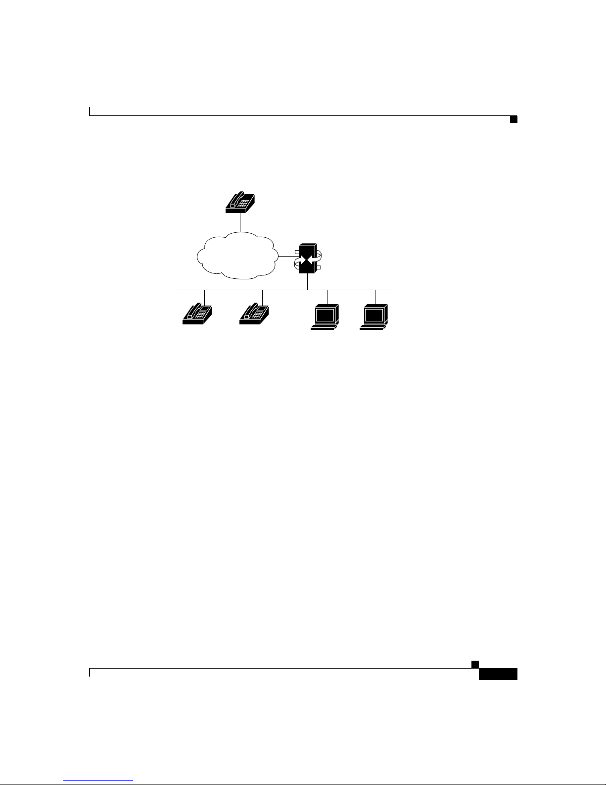
Figure 1-1 Typical VoIP Network
POTS phones
PSTN
Voice over IP Overview
Gateway
TCP/IP network
In a VoIPnetwork,illustrated in Figure 1-1, it is possible for IP telephony devices
to interoperate directly.However, to connect to the PSTN, an intermediary device,
called a gateway, is required. A VoIP gateway, such as the Cisco VG200, allows
users of IP phones and PC-based soft phones to exchange calls with users of plain
old telephone service (POTS) phones on the PSTN. The gateway translates
between the signals used on the PSTN and the IP packets used to transmit data on
a TCP/IP network.
The H.323 Standard
The H.323 standard describes a method for converting between voice and data
transmission formats and for managing connections between telephony
endpoints. H.323 is actually a collection of protocols that define standard methods
for interconnecting H.323 endpoints (sometimes called terminals) and POTS
devices.
IP phones Soft phones
33340
78-10322-02
Software Configuration Guide for the Cisco VG200
1-3
Page 4

Voice over IP Overview
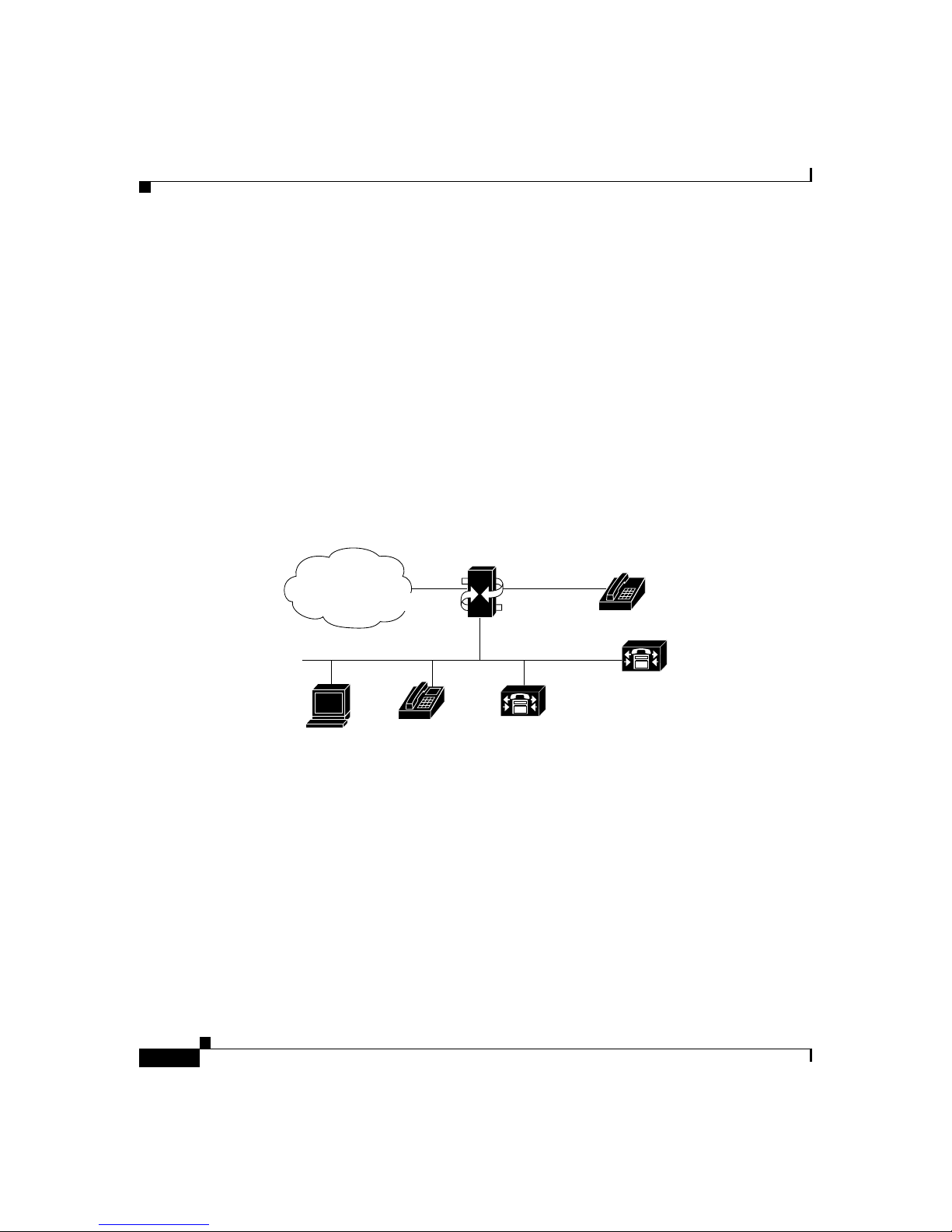
Figure 1-2 The H.323 Standard
POTS phones
H.323 Gateway
PSTN
TCP/IP network
Chapter 1 Using the Cisco Voice Gateway 200
H.323 Proxy
Simple IP
telephony devices
H.323 end point
H.323 Gatekeeper
33341
H.323 endpoints can communicate among each other without the intervention of
any other devices, howevertoconnect them to the PSTN, to manage call setup and
network bandwidth, and to simplify administration, the following devices are
often used:
• H.323 gateway—Connects H.323 devices to POTS devices on the PSTN
• H.323 gatekeeper—Manages network bandwidth and provides a central point
for call administration
• H.323 proxy—An H.323 endpoint that acts as an intermediary between H.323
endpoints and other IP telephony devices
To standardize communication among these devicesand endpoints, H.323 utilizes
the following protocols:
• H.245—Used to negotiate channel usage and capabilities
• H.225—Used for call signaling and call setup
• Registration, Admission and Status (RAS)—Used to communicate with the
H.323 gatekeeper
• Real-Time Protocol/Real-Time Control Protocol (RTP/RTCP)—Used to
create and transmit audio packets on the IP data network
Software Configuration Guide for the Cisco VG200
1-4
78-10322-02
Page 5

Chapter 1 Using the Cisco Voice Gateway 200
H.323 is a peer-to-peer protocol, helping to establish and manage connections
among H.323 endpoints. As with other peer-to-peer protocols, the many-to-many
relationships become difficulttoconfigure and maintain in large networks. MGCP
was developed specifically to overcome the problem of scalability inherent in the
H.323 protocol.
Media Gateway Control Protocol
MGCP establishes a master-slave protocol which, when compared to H.323,
simplifies voice network administration and improves reliability and
performance. In particular, it makes configuration and administration of gateway
devices easy. With MGCP, gateways are defined by MGCP as slave devices in
relation to the master, referred to as a call agent, which manages connections
between endpoints and controls how gateways function.
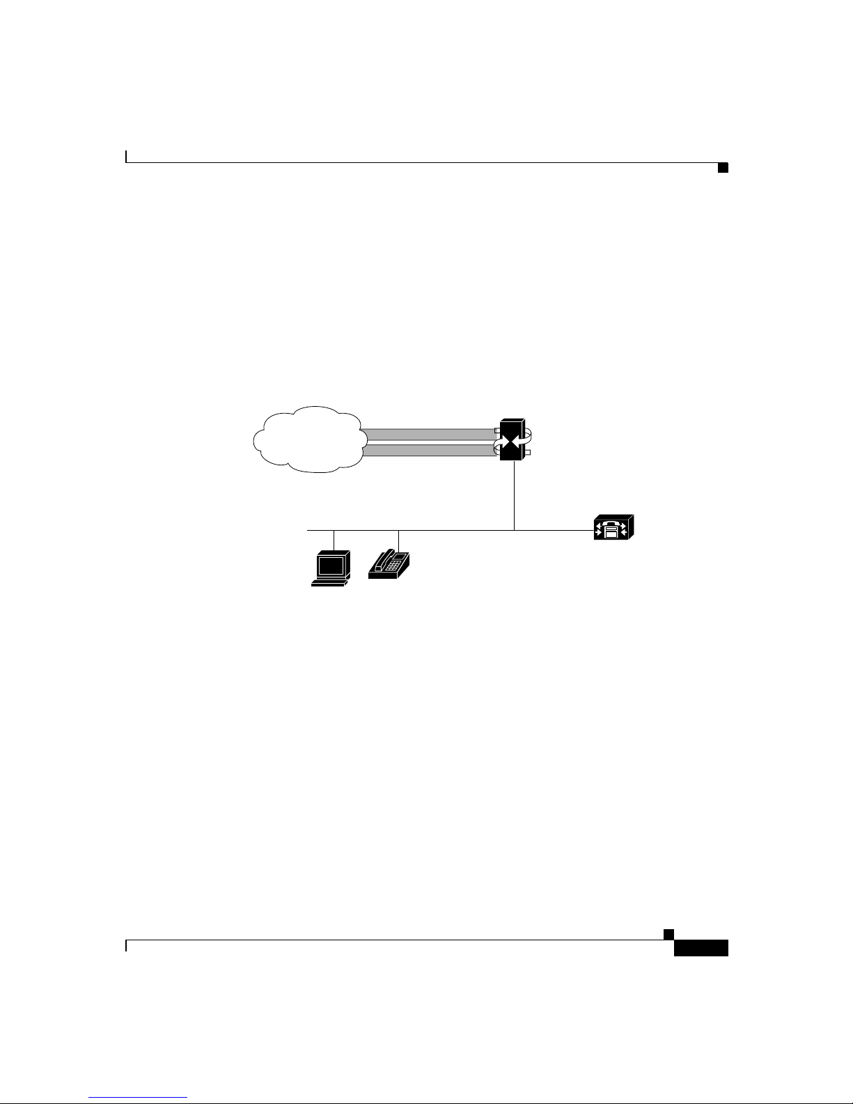
Figure 1-3 MGCP
POTS phones
Voice over IP Overview
78-10322-02
MGCP call agent
MGCP Gateway
PSTN
TCP/IP network
MGCP-managed endpoints
33342
Because an MGCP gateway is a slave device, it derives most of the configuration
it requires from the call agent. Toconfigurean MGCP gateway,all you need to do
is to identify the call agent on the gateway and identify the gateway to the call
agent. In addition, MGCP optionally supports multiple call agents, which can
eliminate a potential single point of failure in the voice network.
Software Configuration Guide for the Cisco VG200
1-5
Page 6
Chapter 1 Using the Cisco Voice Gateway 200
Using the Cisco VG200 with Cisco CallManager
Using the Cisco VG200 with Cisco CallManager
When used with Cisco CallManager 3.0 or later as a call agent, the Cisco VG200
functions as an MGCP gateway. The Cisco VG200 supports MGCP only on its
Foreign Exchange Station (FXS) and Foreign Exchange Office (FXO) analog
ports, while it supports H.323 on its T1 digital ports.
As shown in Figure 1-4, a Cisco VG200 gateway allows you to connect standard
POTS telephones (connected directly to the gateway or anywhere on the PSTN)
with Cisco IP SoftPhones, Cisco IP Phones, or any H.323-compliant telephony
devices. The Cisco VG200 provides a 10/100BaseT Ethernet port for connection
to the data network and a number of different telephony interfaces, depending on
the hardware and software configuration you choose.
Figure 1-4 Using the Cisco VG200 with Cisco CallManager
Voice Gateway
PSTN
FXO ports FXS ports
POTS
phones
10/100BaseT Ethernet
Cisco
CallManager
Cisco
Softphone
Cisco
IP phone
Backup Cisco
CallManager
33344
Currently, the Cisco VG200 supports the following types of analog ports and
connections:
• 1 to 4 FXO ports for connecting to a central office or PBX
• 1 to 4 FXS ports for connecting to POTS telephony devices
• 1 or 2 BRI ports for connecting to ISDN
• 1 or 2 E1/T1 digital ports:
–
For connecting to the PSTN using FXO emulation
–
For connecting to a T1 channel bank using FXS emulation
Software Configuration Guide for the Cisco VG200
1-6
78-10322-02
Page 7

Chapter 1 Using the Cisco Voice Gateway 200
–
For connecting to a PBX by means of a trunk (tie) line using Ear and
Mouth (E&M) emulation
These ports can be used to integrate a VoIP network with POTS devices, PBXs,
ISDN, or the PSTN.
The key to integrating voice and data networks using a Cisco VG200 gateway is
Cisco CallManager, which handles call requests and establishes connections
between IP devices placing and receiving calls.
When you use a Cisco VG200 gateway with H.323, Cisco CallManager can be
used like an H.323 proxy. You can identify the Cisco CallManager server as the
only H.323 endpoint known to the Cisco VG200 gateway on its Ethernet (LAN)
port, so you do not have to configure and maintain a complex dialing plan on the
gateway. This also allows the use of less intelligent IP telephony devices within
an H.323 voice network, because not every device has to function as an H.323
endpoint.
You configure the Cisco VG200 gateway with information about
Cisco CallManager, using the Cisco IOS command line interface (CLI). The
procedures and commands required to perform this configuration are described in
Chapter 3, “Configuring Voice over IP.”
When used with MGCP, you must also configure the Cisco CallManager server
with information about each port on a Cisco VG200 gateway, using the
Cisco CallManager Administrator, a Web-based graphic user interface (GUI).
The Cisco CallManager Administration Guide describes the procedures for
performing this configuration.
Using the Cisco VG200 with MGCP
Using the Cisco VG200 with MGCP
To use a Cisco VG200 gateway with MGCP, you must use Cisco CallManager as
the call agent, and you currently must use an analog voice network module and
FXS or FXO voice interface cards. You use the Cisco IOS CLI to enable MGCP
on the gateway and to identify the Cisco CallManager server. Cisco CallManager
then assumes control over establishing and tearing down connections between IP
endpoints on your network and endpoints connected through the PSTN.
When using MGCP with a Cisco VG200 gateway, all dial-plan related
configuration elements are controlled by Cisco CallManager, and should not be
configured in the Cisco VG200 gateway for MGCP-managed endpoints.
78-10322-02
Software Configuration Guide for the Cisco VG200
1-7
Page 8

Using a Cisco VG200 Gateway with H.323
When you use a Cisco VG200 gateway with Cisco CallManager, you can use its
redundant call agent feature to eliminate a potential single point of failure in the
VoIP network. This feature requires that you have two or three Cisco CallManager
serversavailableonyournetworkand that you identify each of these servers using
CLI commands. You identify the primary Cisco CallManager server as the MGCP
call agent, and identify the second and third Cisco CallManager servers as backup
servers.
Once the redundant call agent feature is configured, if the primary
Cisco CallManager server becomes unavailable, the Cisco VG200 gateway will
register with the backup Cisco CallManager server. The Cisco VG200 gateway
monitors MGCP packets sent by the Cisco CallManager and when no such traffic
is detected, it sends keepalive packets to which the Cisco CallManager server
should respond. If the Cisco VG200 gateway does not detect any packets from the
Cisco CallManager for a specified period, it will try to establish a new connection
with the backup Cisco CallManager server.
Another feature of the Cisco VG200 is called switchback, which refers to the way
that the gateway reestablishes a connection with the primary Cisco CallManager
server when the primary server becomes available again. You can configure the
Cisco VG200 to reestablish connection immediately, or to wait for a specified
length of time to ensure greater stability in the voice network.
Chapter 1 Using the Cisco Voice Gateway 200
Using a Cisco VG200 Gateway with H.323
The Cisco VG200 functions as an H.323 gateway with the following voice
interface types, which are currently not supported with MCGP:
• E1 (R2 and E&M analog emulation)
• T1-CAS (FXO, FXS, and E&M emulation)
• E1-PRI
• T1-PRI
• ISDN/BRI
• E&M
Note that H.323 configuration is more complicated compared to MGCP and does
not provide for redundant call agents. The following sections describe how to use
the Cisco VG200 with H.323 with various interface and signalling types:
Software Configuration Guide for the Cisco VG200
1-8
78-10322-02
Page 9

Chapter 1 Using the Cisco Voice Gateway 200
• T1-CAS Analog Port Emulation, page 1-9
• FXO Emulation, page 1-10
• FXS Emulation, page 1-11
• E&M Emulation, page 1-11
• Linking PBX Users with E&M Trunk Lines, page 1-12
• Direct-Inward Dialing on a BRI Port, page 1-13
T1-CAS Analog Port Emulation
T1 is a digital signaling standard that uses time-division multiplexing (TDM) to
dividethe available bandwidth of 1.544 Mbps into twenty-four 64-kbps timeslots.
E1 is a similar standard, commonly used in Europe and many parts of Asia, which
provides 2.048 Mbps bandwidth, divided into 32 time slots, with 30 time slots
available for voice conversations.
A DS-0 group is a group or collection of DS-0 timeslots. Each of these DS-0
groups can be used to emulate an FXO analog connection to the PSTN, an FXS
analog connection to a T1 channel bank, or an E&M connection for enabling a
trunk (tie) line.
When you configure your DS-0 groups, you can configure DS-0 hunt groups,
which allow any available voice port to be used for a range of phone numbers.
This eliminates the chance that a single DS-0 could fail, or that a DS-0 is busy at
the time of a call.
To use a Cisco VG200 gateway to interconnect a VoIP network and a T1
connection, you configure from 1 to 24 DS-0 groups for each T1 connection, and
then defineavoiceportfor each DS-0 group. The Cisco VG200currently supports
T1 connections using channel associated signaling (CAS).
You can use DS-0 groups with FXO analog port emulation to connect to a PSTN
central office (CO). When connecting T1-CAS to the PSTN, either the
Cisco VG200 gateway or the Cisco CallManager must be able to identify the
dialed number (DNIS) of each call and route it to the appropriate endpoint on the
IP network.
Using a Cisco VG200 Gateway with H.323
78-10322-02
Software Configuration Guide for the Cisco VG200
1-9
Page 10

Using a Cisco VG200 Gateway with H.323
FXO Emulation
Figure 1-5 Using FXO Analog Emulation with T1-CAS
PSTN
T1-CAS
DS-0 groups 0-23
DS-0 groups 0-23
FXO emulation
DID incoming lines
10/100BaseT Ethernet
Chapter 1 Using the Cisco Voice Gateway 200
Port 0
Voice Gateway
Gateway
Port 1
Cisco CallManager
H.323 endpoint
Simple IP
telephony devices
33345
To make this work you must obtain Direct Inward Dialing (DID) service from
your local exchange carrier (LEC) on the DS-0 groups used for incoming calls.
DID service is provided only on incoming connections, so to use it, you must
divide your T1 channels into incoming and outgoing DS-0 groups.
You can configureyour dial plan on a Cisco VG200 gateway, using Cisco IOS CLI
commands to identify the destination endpoint and coder-decoder (CODEC) for
each incoming call on each DS-0 group. This is a straightforward task, but this
method of configuration does not take full advantage of the Cisco CallManager
and can only be used for H.323 endpoints.
You can configure a Cisco VG200 gateway to direct all incoming calls to the
Cisco CallManager, and configure your dial plan using the Cisco CallManager
Administrator. This simplifies administration and lets you connect simple IP
telephony devices (such as the Cisco IP Phone 7960 and Cisco IP SoftPhone) to
the PSTN. This configuration is described in Chapter 3, “Configuring Voice over
IP.”
Software Configuration Guide for the Cisco VG200
1-10
78-10322-02
Page 11
Chapter 1 Using the Cisco Voice Gateway 200
FXS Emulation
As shown in Figure 1-6, you can use FXS analog signalling with the T1-CAS port
option to interconnect the PSTN and a Voice over IP network. In this
configuration, you define the DS-0 groups as FXS and create a dialing plan to
ensure that calls can be routed and set up between endpoints on the VoIP network
and the POTS devices on the T1 channel bank.
Figure 1-6 Using FXS Analog Emulation with T1-CAS
Using a Cisco VG200 Gateway with H.323
E&M Emulation
As shown in Figure 1-7, you can use the T1-CAS port on a Cisco VG200 gateway
with E&M analog emulation. E&M signalling emulation lets you use a
Cisco VG200 gateway to interconnect H.323 devices on a VoIP network with
POTS devices over a standard trunk (tie) line.
DS-0 groups 0-23
PSTN
DS-0 groups 0-23
FXS emulation
10/100BaseT Ethernet
Simple IP
telephony devices
T1-CAS
Port 0
Voice Gateway
Port 1
Cisco CallManager
H.323 endpoint
33470
78-10322-02
Software Configuration Guide for the Cisco VG200
1-11
Page 12

Using a Cisco VG200 Gateway with H.323
Figure 1-7 Using E&M Analog Emulation with T1-CAS
Chapter 1 Using the Cisco Voice Gateway 200
PBX
10/100BaseT Ethernet
Simple IP
telephony devices
T1-CAS
DS-0 groups 0-23
DS-0 groups 0-23
E&M emulation
Trunk (tie) line
Port 0
Port 1
1 or 2
T1 ports
Voice
Linking PBX Users with E&M Trunk Lines
The followingexampleshowshowtoconfigureVoIPtolinkPBX users with E&M
trunk lines.
In this example, a company wants to connect two offices: one in San Jose,
California and the other in Salt Lake City, Utah. Each office has an internal
telephone network using PBX, connected to the voice network by an E&M
interface. Both the Salt Lake City and the San Jose offices are using E&M Port
Type II, with four-wire operation and Immediate Start signaling. Each E&M
interface connects to the gateway using two voice interface connections. Users in
San Jose dial “8-569” and then the extension number to reach a destination in Salt
Lake City. Users in Salt Lake City dial “4-527” and then the extension number to
reach a destination in San Jose.
Figure 1-8 illustrates the topology of this connection example.
Gateway
Cisco CallManager
33471
Software Configuration Guide for the Cisco VG200
1-12
78-10322-02
Page 13

Chapter 1 Using the Cisco Voice Gateway 200
Figure 1-8 Linking PBX Users with E&M Trunk Lines Example
Using a Cisco VG200 Gateway with H.323
IP cloud
Gateway 1 Gateway 2
San Jose
(408)
This example assumes that the company already has established a working IP
connection between its two remote offices. PBXs should be configured to pass all
DTMF signals to the gateway. Cisco recommends that you do not configure
“store-and-forward” tone.
Note If you change the gain or the telephony port, make sure that the
telephony port still accepts DTMF signals.
Direct-Inward Dialing on a BRI Port
The following example shows how to configure a BRI port for direct-inward
dialing (DID). This configuration allows the called number information from the
ISDN Q.931 setup message to be used for routing on an ISDN line.
In this example, a call comes in to gateway 1 on the BRI port. The DID
information allows the gateway to route the call based on the called number.If the
called number is 2xxx, the call is routed to gateway 2000, and if the called number
is 3xxx, the call is routed to gateway 3000.
Figure 1-9 illustrates the topology of this connection example.
Salt Lake City
48464
(801)
78-10322-02
Software Configuration Guide for the Cisco VG200
1-13
Page 14

Where to Go Next
Chapter 1 Using the Cisco Voice Gateway 200
Figure 1-9 Configuring DID on a BRI Port
Gateway 2
BRI port
Where to Go Next
Now that you understand something about the different ways that you can use a
Cisco VG200 gateway, you should proceed to Chapter 2, “Basic Configuration.”
Chapter 2 describes the procedures required to configure your Cisco VG200
gateway, however you choose to use it. Even if you are familiar with other Cisco
products, you should refer to Chapter 2 because the configuration of a
Cisco VG200 gateway is a little different from Cisco routers.
After completing the basic configuration required to use a Cisco VG200 gateway,
you can refer to Chapter 3, “Configuring Voice over IP,” for detailed instructions
about configuring a Cisco VG200 gateway for MGCP or H.323.
Gateway 1
IP cloud
FXS port
Gateway 3
FXS port
48465
Software Configuration Guide for the Cisco VG200
1-14
78-10322-02
 Loading...