

Cisco vEdge Series, vEdge 100, vEdge 100m, vEdge 100wm, vEdge 1000 Hardware Installation Manual
...Page 1
Hardware Installation Guide for vEdge Routers
First Published: 2018-03-27
Americas Headquarters
Cisco Systems, Inc.
170 West Tasman Drive
San Jose, CA 95134-1706
USA
http://www.cisco.com
Tel: 408 526-4000
800 553-NETS (6387)
Fax: 408 527-0883
Page 2

©
Cisco Systems, Inc. All rights reserved.
Page 3

CONTENTS
CHAPTER 1
CHAPTER 2
vEdge 100 Router 1
Declaration of Conformity 2
Components and Specifications 2
Front and Rear Panel Components 4
Ports and Connectors 6
Power Supply and Cooling System 7
General Safety Standards 8
Site Preparation Guidelines 9
Install the vEdge 100 Router 10
Connect the vEdge 100 Router 16
vEdge 100 Router Default Configuration 19
Maintenance and Troubleshooting 20
Restore a vEdge Router 22
Return Hardware 23
vEdge 100b Router 27
Declaration of Conformity 28
Components and Specifications 29
Front and Rear Panel Components 31
Ports and Connectors 33
Power Supply 33
Planning and Installation 34
Prepare for Router Installation 35
Install the vEdge 100b Router 36
Connect the vEdge 100b Router 40
vEdge 100b Router Default Configuration 43
Hardware Installation Guide for vEdge Routers
iii
Page 4

Contents
Maintenance and Troubleshooting 46
Restore a vEdge Router 47
Return Hardware 48
CHAPTER 3
vEdge 100m Router 51
At a Glance 52
Declaration of Conformity 52
Components and Specifications 53
Components and Specifications 53
Front and Rear Panel Components 57
Ports and Connectors 60
Power Supply and Cooling in a Cisco vEdge 100m Router 61
Planning and Installation 61
Planning and Installation 61
Prepare for Router Installation 62
Install the vEdge 100m Router 63
Connect the vEdge 100m Router 69
vEdge 100m Router Default Configuration 72
Maintenance and Troubleshooting 77
Maintenance and Troubleshooting 77
CHAPTER 4
Restore a vEdge Router 78
Return Hardware 79
vEdge 100wm Router 83
Declaration of Conformity 84
Components and Specifications 85
Front and Rear Panel Components 89
Ports and Connectors 92
Power Supply and Cooling System 93
Planning and Installation 93
Prepare for Router Installation 94
Install the vEdge 100wm Router 95
Connect the vEdge 100wm Router 102
Maintenance and Troubleshooting 105
Hardware Installation Guide for vEdge Routers
iv
Page 5

Restore a vEdge Router 107
Return Hardware 108
Contents
CHAPTER 5
vEdge 1000 Router 111
Declaration of Conformity 112
Components and Specifications 113
Front Panel Components 115
Supported Transceivers 117
Ports and Connectors 120
Power Supply and Cooling in Cisco vEdge 1000 Routers 126
Field-Replaceable Units 128
USB Dongle for Cellular Connection 128
Planning and Installation 130
Prepare for Router Installation 131
Install the vEdge 1000 Router 132
Connect the vEdge 1000 Router 144
vEdge 1000 Router Default Configuration 149
Maintenance and Troubleshooting 150
Install a Transceiver 152
CHAPTER 6
Remove a Transceiver 153
Restore a vEdge Router 154
Return Hardware 155
vEdge 2000 Router 159
Declaration of Conformity 160
Components and Specifications 161
Front Panel Components 163
PIM and Transceiver Modules 165
Supported Transceivers 171
Ports and Connectors 173
Field-Replaceable Units 180
Power Supply and Cooling in Cisco vEdge 2000 Routers 181
Planning and Installation 183
Prepare for Router Installation 184
Hardware Installation Guide for vEdge Routers
v
Page 6

Contents
Install the vEdge 2000 Router 185
Connect the vEdge 2000 Router 194
Install vEdge 2000 Router Components 198
vEdge 2000 Router Default Configuration 202
Maintenance and Troubleshooting 203
Remove vEdge 2000 Router Components 205
Restore a vEdge Router 209
Return Hardware 210
CHAPTER 7
vEdge 5000 Router 213
Declaration of Conformity 214
Components and Specifications 215
Front and Rear Panel Components 217
NIM and Transceiver Modules 220
Supported Transceivers 225
Ports and Connectors 227
Field-Replaceable Units 234
Power Supply and Cooling in Cisco vEdge 5000 Routers 234
Planning and Installation 237
Prepare for Router Installation 238
Connect the vEdge 5000 Router 239
vEdge 5000 Router Default Configuration 241
Maintenance and Troubleshooting 243
Remove vEdge 5000 Router Components 244
Restore a vEdge Router 248
CHAPTER 8
vi
Return Hardware 249
vEdge Cloud Router 253
Declaration of Conformity 254
Hardware Installation Guide for vEdge Routers
Page 7
CHAPTER 1
vEdge 100 Router
The vEdge 100 router delivers highly secure site-to-site data connectivity to small business and home offices
(SOHO). The vEdge 100 router is a fixed-port-configuration router with the following features:
• Five built-in 10/100/1000 Mbps Ethernet ports
• Power over Ethernet (PoE) source support on one Ethernet port
• Encryption and QoS support
• 100 Mbps forwarding throughput (inclusive of encryption)
• Secure identification chip for anti-counterfeit and secure authentication
• Integrated power supply
• Kensington security lock slot to physically lock down the router
• GPS input for geographical location
• Desktop mount, wall mount, or rack-mountable in a 19-inch rack
Chassis Views
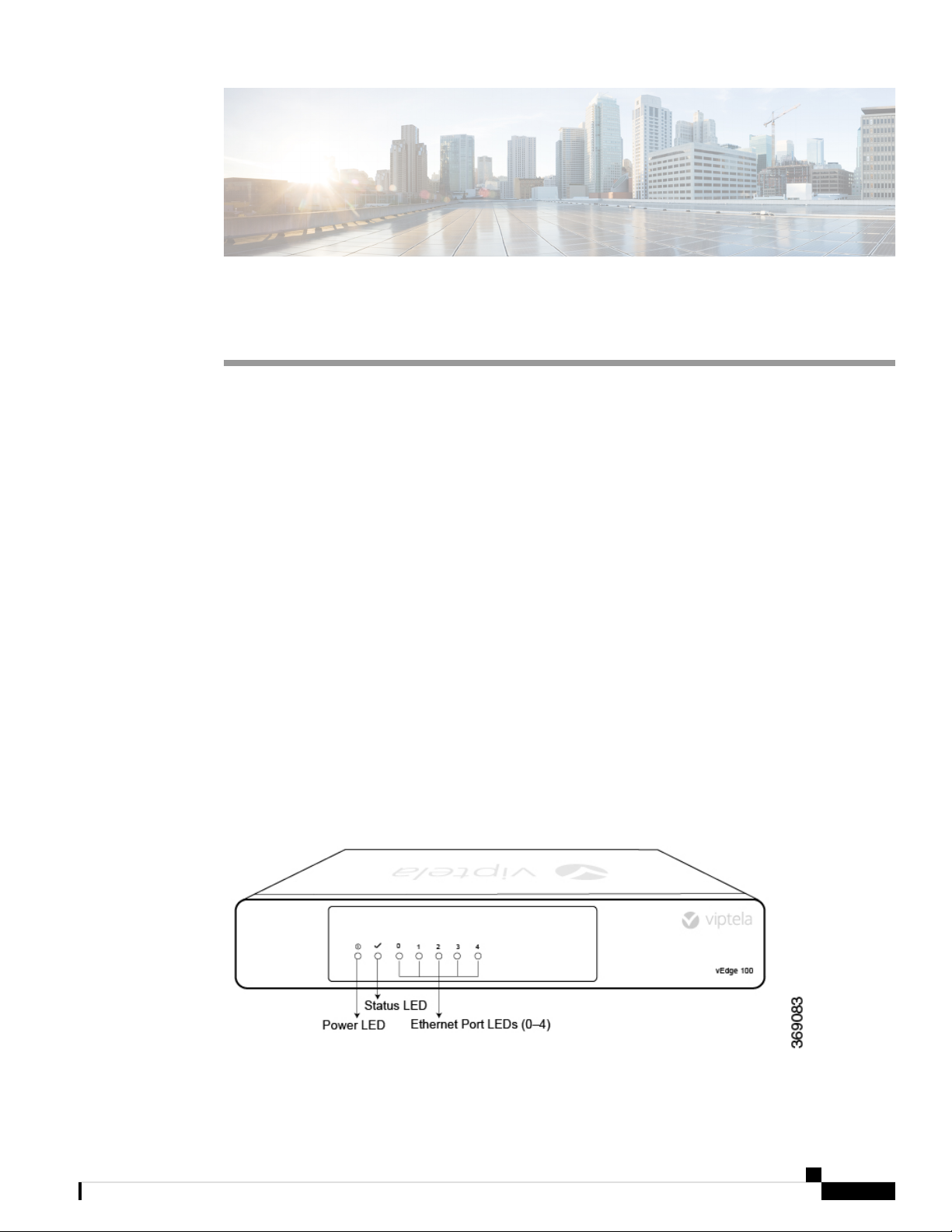
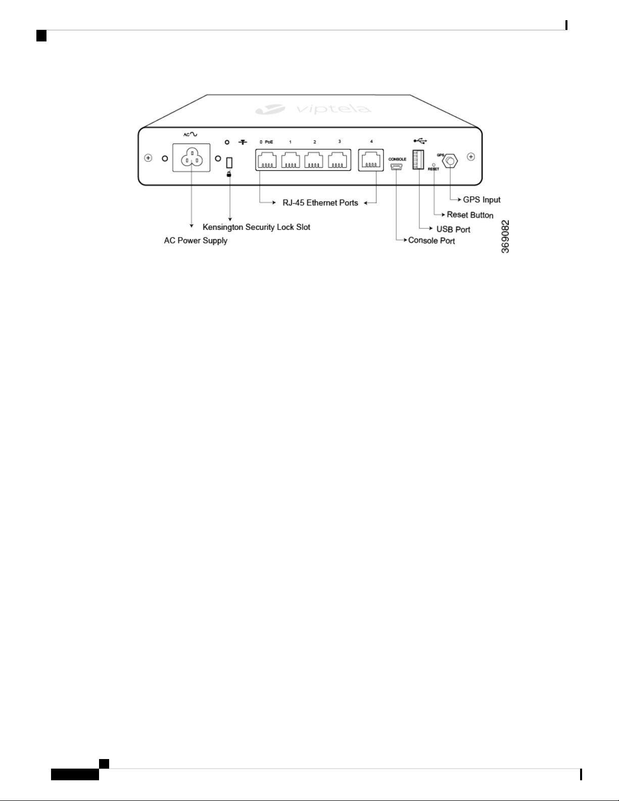
Figure 1 and Figure 2 show the front and back panels of the vEdge 100 router, indicating the location of the
power interfaces, status indicators, and chassis identification labels.
Figure 1: Front Panel of the vEdge 100 Router
Figure 2: Back Panel of the vEdge 100 Router
Hardware Installation Guide for vEdge Routers
1
Page 8
Declaration of Conformity
vEdge 100 Router
• Declaration of Conformity, on page 2
• Components and Specifications, on page 2
• General Safety Standards, on page 8
• Maintenance and Troubleshooting, on page 20
Declaration of Conformity
The Viptela products are controlled under the Commerce Control List (CCL) of the U.S. Export Administration
Regulations (EAR) as networking equipment within the following U.S. Export Control Classification Numbers
(ECCN): 5A002, 5D002, and 5E002.
The vEdge hardware and software products and the Viptela encryption technology can be delivered to most
end users and destinations worldwide without a licensing requirement. The Viptela solution and products
have undergone a one-time review by the Government of the United States of America and qualify for License
Exception ENC. As such, they are eligible for export according to Section 740.17 of the EAR.
The Viptela solutions and products can be delivered to most end users worldwide, except to entities or end
users in the following countries: Cuba, Iran, North Korea, Sudan, and Syria.
Controlled Technologies
Viptela manages technology subject to the U.S. Export Administration Regulations (EAR). These controlled
technologies may include items under U.S. ECCN 5E002 encryption technology. The Viptela encryption
technology is for the development, production, and use of Viptela products that implement or use encryption.
The Viptela software distribution policy allows only authenticated users to download the Viptela encryption
software. Recipients of controlled technology are obliged to maintain adequate controls to prevent nationals
from outside the U.S. and Canada from accessing Viptela information, subject to ECCN5E002, without first
obtaining authorization from the U.S. government.
For additional information on controlled technologies, please contact Viptela support at support@viptela.com
.
Components and Specifications
This article provides the chassis specifications of the vEdge 100 router and lists the other router components.
Hardware Installation Guide for vEdge Routers
2
Page 9

vEdge 100 Router
Components and Specifications
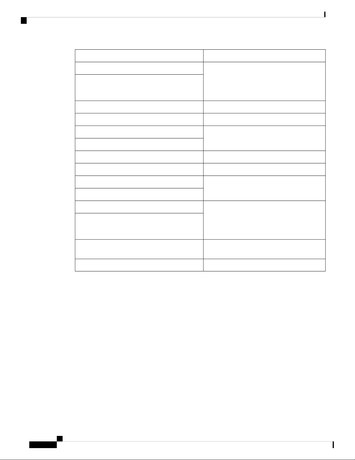
Chassis Specifications
Table 1 lists the specifications for the vEdge 100 router chassis.
Table 1:
SpecificationItem
Services and Slot Density
RJ45 Ports 10/100/1000 Mbps
rate 115.2 Kbps)
Power Specifications
AC input voltage
Physical Specifications
5 ports, one of which has 802.3af PoE source
capability
YesEmbedded hardware-based crypto acceleration (IPSec)
2 GBMemory DDR3 ECC DRAM
4 GBNAND storage (internal)
1USB host port (Type A USB 3.0)
1Mini USB connector console port (default baud
AC Input (C6 inlet connector)Power supply
90-264 Vrms
47-63 HzAC input line frequency
15 WattsTypical power consumption with PoE disabled on ge0/0
32 Watts maximumTypical power consumption with PoE enabled on ge0/0
Chassis height
Packaging Specifications
Package height
1.5 in. (3.8 cm)
9 in. (22.9 cm)Chassis width
5.5 in. (14 cm)Chassis depth
Can be accommodated in 1 RURack height
3.1 lb (1.4 kg)Chassis weight
Provided with the unitRack-mount accessory kit 19 in (48.3 cm) EIA
2.5 in. (6.4 cm)
12.4 in. (31.6 cm)Package width
9.6 in. (24.4 cm)Package depth
Hardware Installation Guide for vEdge Routers
3
Page 10
Front and Rear Panel Components
Operating Condition
vEdge 100 Router
SpecificationItem
Temperature
Transportation/Storage Condition
Temperature
Reliability
MTBF
Regulatory Compliance
Safety
EMC
0 to 40°C (32 to 104°F) at sea level ( temperature
de-rating of 1.5 deg C per 1000 feet of altitude
applicable up to max of 10000 feet or 3000 m)
Max 3000 m (10000 ft)Altitude
10 to 85% RHHumidity
-40 to 70°C (-40 to 158°F)
5 to 95%RHHumidity
4570 m (15000 ft)Altitude
104K hours
AS/NZS 60950-1 CAN/CSA 60950-1
CB-IEC60950-1 CE Marking EN 60950-1
UL60950-1
AS/NZS CISPR22 Class A EN 300 386 EN 55022
Class A FCC Class A ICES Class A VCCI Class A
Front and Rear Panel Components
This article describes the components on the front and rear panels of the vEdge 100 router. See At a Glance
for the exact location of these components on the router.
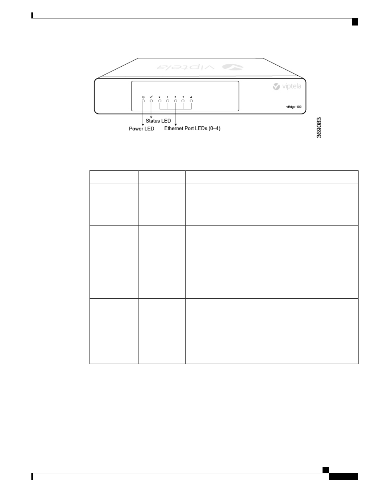
Front Panel LEDs
The vEdge 100 router has five chassis status LEDs located in the front. See Figure 1.
Figure 1: Chassis Status LEDs in a vEdge 100 Router
ROHS 6/6Environmental
Hardware Installation Guide for vEdge Routers
4
Page 11
vEdge 100 Router
Front and Rear Panel Components
Table 1 describes the LEDs , their color and states, and the status they indicate.
Table 2:
StatusColorLED
(LED 0–4)
Green/RedPower
• Off: System is not on
• Green: System is healthy and operating fine
• Red: Power supply fault
Green/Yellow/RedStatus
• Off: System is not on
• Solid Green: System is fully functional
• Blinking Green: System is booting up
• Solid Yellow: No Internet connectivity or the system has detected
a minor alarm
• Red: System has detected a major system level fault or alarm
Green/YellowEthernet Port
• Off: No link
• Solid Green: 1000 Mbps link detected
• Blinking Green: 1000 Mbps link detected and link activity
• Solid yellow: 10/100 Mbps link detected
• Blinking Yellow: 10/100 Mbps link detected and link activity
Rear Panel
The rear panel of the vEdge 100 router has a Reset button, a Kensington security lock slot, and a GPS antenna
input. See Chassis Views for the location of these components.
Reset Button
The Reset button on the rear panel is recessed, to avoid accidentally pressing it while the router is operational.
To press the Reset button, use a sharp narrow tool. Table 2 describes the effects of pressing the Reset button.
Hardware Installation Guide for vEdge Routers
5
Page 12
Ports and Connectors
vEdge 100 Router
Table 3:
BehaviorPress
Duration
Pressing for two seconds resets and reboots the router.Short press
Pressing for 10 seconds resets the router and reboots it with factory default configuration.Long press
Kensington Security Lock Slot
The rear panel of the vEdge 100 router has a small metal-enforced hole for attaching a Kensington lock to
secure the router.
GPS Input
The GPS antenna input on the rear panel of the router allows you to connect an external GPS antenna that has
an SMA connector. If you connect a GPS antenna to the router, it can automatically identify the router's
geographical location.
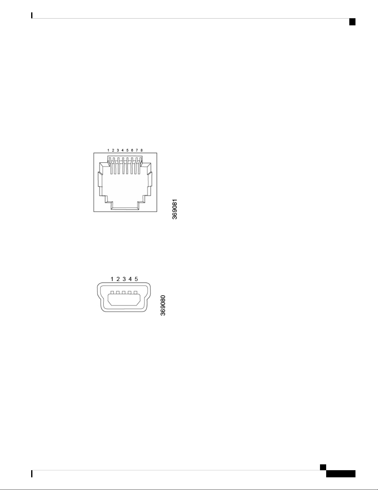
Ports and Connectors
The vEdge 100 router supports three types of ports: RJ-45 Ethernet ports, USB port, and USB serial console
port.
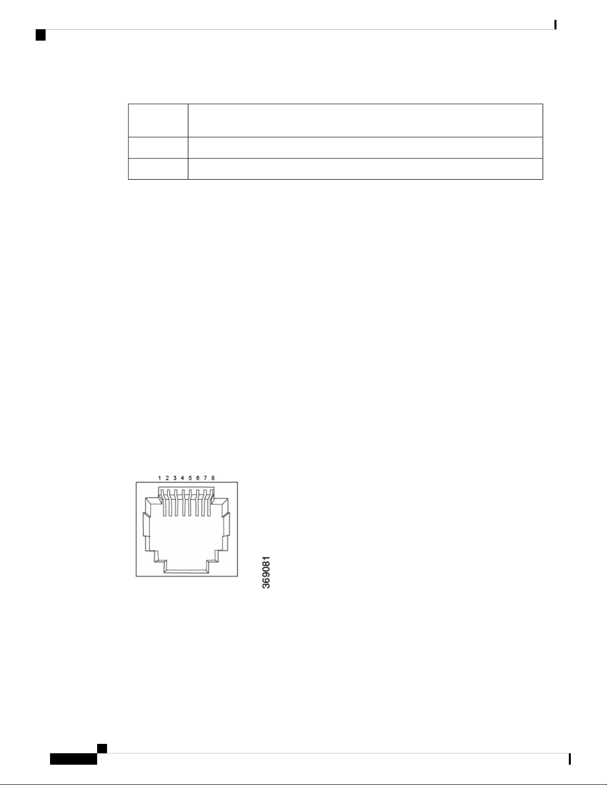
RJ-45 Ethernet Ports
There are five built-in RJ-45 Ethernet ports on the vEdge 100 router. These ports support 10/100/1000 Mbps
and are numbered 0 through 4. Port 0 supports PoE capability.
Figure 1 provides the pinout information for the RJ-45 ports. The RJ-45 ports comply with the 801 standards.
Figure 1: RJ-45 Ports Pinout Information
USB Port
There is one USB port on the vEdge 100 router with a type A connector. The USB port complies with USB
3.0 specification.
Hardware Installation Guide for vEdge Routers
6
Page 13
vEdge 100 Router
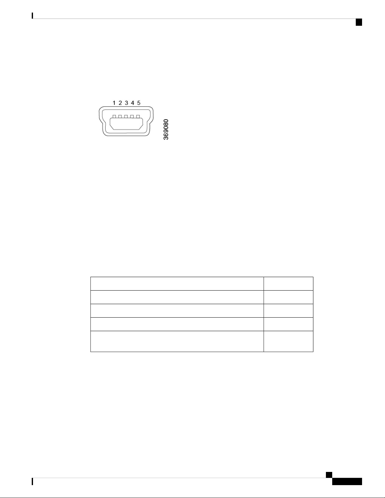
Console Port
The console port on the vEdge 100 router is a serial port and is accessible via a USB Mini-B connector. See
Figure 2.
Figure 2: USB Mini-B Connector
A USB Type-A to Mini-B connector cable is shipped with the vEdge 100 router as standard accessory for
console port connection.
Power Supply and Cooling System
The vEdge 100 router has an built-in AC-to-DC power supply unit. Read this article to learn more about the
AC power supply in the router as well as about the cooling system and airflow through the router chassis.
Power Supply and Cooling System
AC Power Supply in vEdge 100 Router
The vEdge 100 router has an integrated AC power supply that exposes a C6 male AC inlet connector externally.
The unit can be powered by connecting the supplied power cord to AC mains with the C5 female connector
end of power cord plugged into the unit.
Table 1 describes the AC power supply specifications for the vEdge 100 router.
Table 4:
SpecificationItem
90-264 VrmsAC input voltage
47-63 HzAC input line frequency
15 WattsTypical power consumption with PoE disabled on transport interface
Typical power consumption with PoE enabled on transport interface
32 Watts
maximum
AC Power Cord Specifications
The vEdge 100 router ships with a detachable AC power cord. The power cord has a C5 female connector at
one end and the other end is specific to the country/locality to which the product is shipped.
Cooling System in a vEdge 100 Router
The cooling system in a vEdge 100 router consists of internal heat sinks and an internal fan with adjustable
speed. The fan speed is algorithmically controlled, based on readings obtained from internal temperature
sensors that in turn is determined by factors such as external ambient as well as the traffic workload.
Hardware Installation Guide for vEdge Routers
7
Page 14
General Safety Standards
If the ambient temperature inside the chassis rises above the acceptable range, the router raises an alarm. If
the temperature inside the chassis rises above the maximum threshold temperature, the router shuts down
automatically.
General Safety Standards
vEdge 100 Router
Caution
Caution
Before removing or installing router modules and components, ensure that the router chassis is electrically
connected to ground. Ensure that you attach an ESD grounding strap to an ESD point and place the other end
of the strap around your bare wrist making good skin contact. Failure to use an ESD grounding strap could
result in damage to the router.
Some router components are hot-swappable and hot-insertable. You can remove and replace them without
powering off or disconnecting power to the router. Do not, however, install the router or any of its component
if they appear to be damaged.
• Install your vEdge router in compliance with the following local, national, and international electrical
codes:
• United States—National Fire Protection Association (NFPA 70), United States National Electrical
Code.
• Other countries—International Electromechanical Commission (IEC) 60364, Part 1 through Part
7.
• Evaluated to the TN power system.
• Canada—Canadian Electrical Code, Part 1, CSA C22.1.
• Permit only trained and qualified personnel to install or replace switch components.
• Locate the emergency power-off switch in the room in which you are working. In case of an electrical
accident, quickly turn off the power.
• Disconnect power before installing or removing the router.
• If an electrical accident occurs, use caution and immediately turn off power to the router.
• Make sure that grounding surfaces are thoroughly cleaned and well-finished before grounding connections
are made.
• Do not work alone if hazardous conditions exist.
• Always check that power is disconnected from a circuit. Never assume that it is disconnected.
• Carefully inspect your work area for possible hazards, such as moist floors, worn-out power cords,
ungrounded power extension cords, and missing safety grounds.
• Operate the device within marked electrical ratings and product usage instructions.
• To ensure that the router and the FRUs function safely and correctly, use the specified cables and
connectors, and make certain they are in good condition.
Hardware Installation Guide for vEdge Routers
8
Page 15
vEdge 100 Router
Site Preparation Guidelines
Efficient operation of routers requires proper site planning and proper layout of your equipment rack or wiring
closet:
• Ensure that the area around the router is kept free of dust and conductive material.
• Follow appropriate airflow guidelines so that the cooling system functions normally.
• Follow ESD prevention procedures to avoid any damage to the router.
• Install the router in an enclosed, secure area allowing only authorized personnel to access the device.
Environmental Requirements
Install the vEdge routers in a dry, clean, temperature-controlled, and well-ventilated environment:
• Maintain ambient airflow for the router to operate normally. The ambient intake air temperature should
be in the range 0°C to 40°C (32°F to 104°F). If the airflow is blocked or if the air intake is too warm,
the router can get overheated.
Site Preparation Guidelines
• Avoid temperature extremes. Ensure that the router is operating at an ambient temperature not more that
40°C (104°F) at sea level. For higher altitudes, a derating of 1.50°C per 1,000 feet applies.
• High humidity conditions can cause moisture to penetrate into the chassis. The devices support 10% to
85% humidity levels, non-condensing.
Rack Requirements
For the Cisco vEdge router models that support the rack mount option, you can mount the routers in a two-post
or a four-post rack. Table 1 provides the rack requirements for the routers.
Table 5:
GuidelinesRack Requirement
Rack type
Use a two-post or a four-post rack that meets the size requirements for the router,
provides bracket holes or hole patterns spaced at 1 U (1.75 in. or 4.45 cm)
increments, and is strong enough to support the weight of the router.
Mounting brackets
Ensure that the holes in the mounting brackets are spaced at 1 U (1.75 in. or 4.45
cm). This allows you to mount the router in any location in the rack.
Rack size
It is recommended that the rack comply with the size and strength standards of a
19-inch rack as defined in Cabinets, Racks, Panels, and Associated Equipment
(document number EIA-310–D), published by the Electronics Industry Association
http://www.eia.org . Ensure that the rack rails are spaced widely enough to
accommodate the external dimensions of the chassis and that the outer edges of
the front mount brackets extend the width of the chassis to 19 in. (48.2 cm). You
must also ensure that the spacing of rails and adjacent racks allows for the proper
clearance around the router and rack.
building structure
For maximum stability, secure the rack to ceiling brackets and to floor brackets.Rack secured to
Hardware Installation Guide for vEdge Routers
9
Page 16

Install the vEdge 100 Router
Airflow Requirements
When planning your site for installing vEdge routers, allow enough clearance around the installed router.
Since the routers work with a front-to-back airflow there are no clearance requirements for the sides, but it is
recommended that you provide at least 3 in. of clearance at the back.
Install the vEdge 100 Router
Once you have prepared your site for router installation, unpack the vEdge 100 router and mount it either on
the wall or in a 19-inch rack.
Unpack the vEdge 100 Router
A vEdge 100 router is shipped in a cardboard carton and secured firmly in place with foam packing material.
The carton contains a packing list and Quick Start instructions. It is recommended that you do not unpack the
router till you are ready to install it.
To unpack the router:
1. Open the top flaps of the carton.
vEdge 100 Router
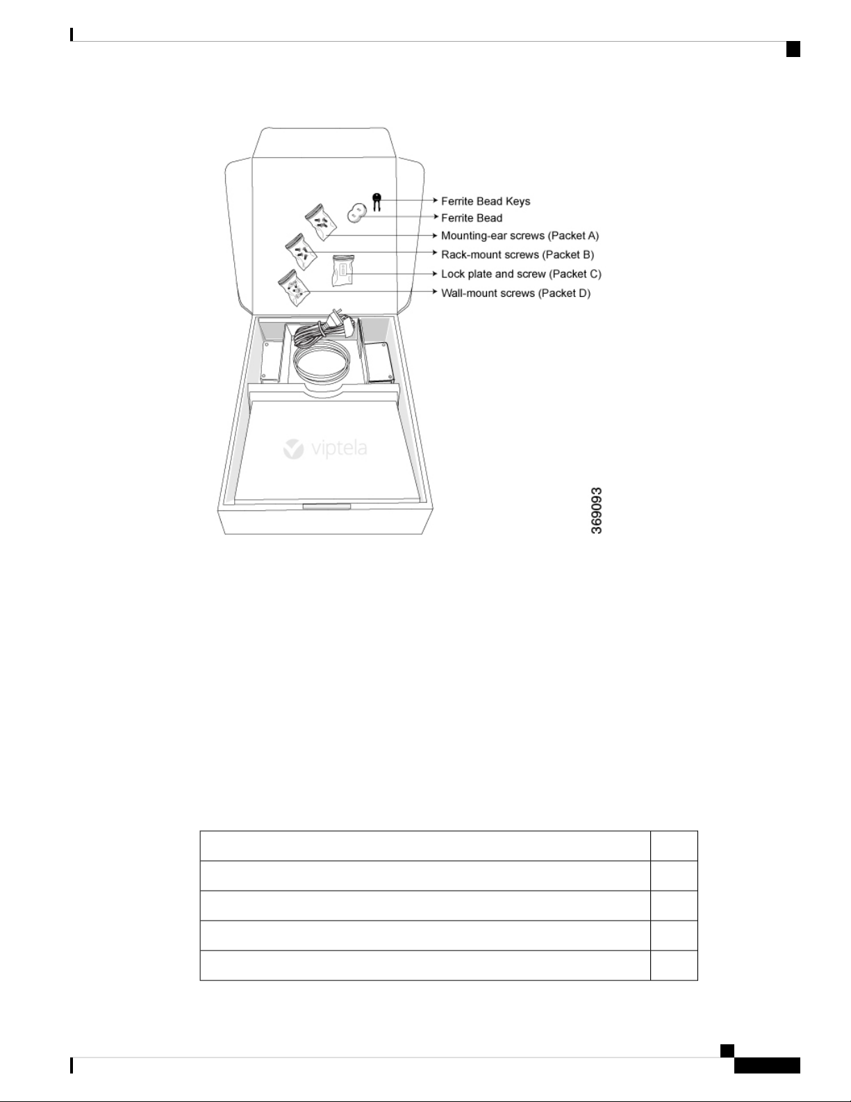
2. Gradually remove the packing foam holding the router and the accessories in place. See Figure 1.
3. Take out the router and each accessory.
4. Verify the router components against the packing list included in the box (see packing list below).
Figure 1: Unpacking the vEdge 100 Router
Hardware Installation Guide for vEdge Routers
10
Page 17
vEdge 100 Router
Install the vEdge 100 Router
Note: It is recommended that you do not discard the shipping carton and packing material when you unpack
the router. Flatten and store the box in case you need to move or return the router in the future. See Return
Hardware .
Packing List for a vEdge 100 Router
The cardboard carton in which the router is packed includes a packing list. Check the parts you receive with
your router against the items on the packing list. The packing list specifies the part number, name, and quantity
of each item in the carton.
If any part on the packing list is missing, contact your customer service representative or contact Viptela
customer support from within the U.S. or Canada by telephone at 800-525-5033 or by email to
support@viptela.com .
Table 1 lists the parts shipped with the vEdge 100 router and their quantities.
Table 6:
QuantityComponent
1Router chassis
1AC power cord appropriate for your geographical location (ferrite bead attached)
1USB console cable
1 + 1Ferrite bead and key (to be attached to the USB cable)
Hardware Installation Guide for vEdge Routers
11
Page 18
Install the vEdge 100 Router
Mount the vEdge 100 Router
You can mount the vEdge 100 router in one of the following ways:
vEdge 100 Router
QuantityComponent
2Mounting ears, left and right
1Wall-mount bracket
4Mounting ears screws (Packet A)
4Rack-mount screws (Packet B)
1Lock plate and screw (Packet C)
4Wall-mount screws (Packet D)
1Quick Start document
• Mount the router in a 19-inch rack
• Mount the router on the wall
In addition to the accessory box, you need the following tools to mount a vEdge 100 router:
• Number 2 Phillips (+) screwdriver
• Tape measure or level
Mount the vEdge 100 Router in a Rack
You can mount the vEdge 100 router on two front posts in a 19-inch rack using simple rack mount ear
accessories. To do so:
1. Place the router chassis on the floor or on a sturdy table near the rack.
2. Verify the internal dimensions of the rack with a tape measure. The rack-mount tray is 440 mm wide and
must fit within the mounting posts.
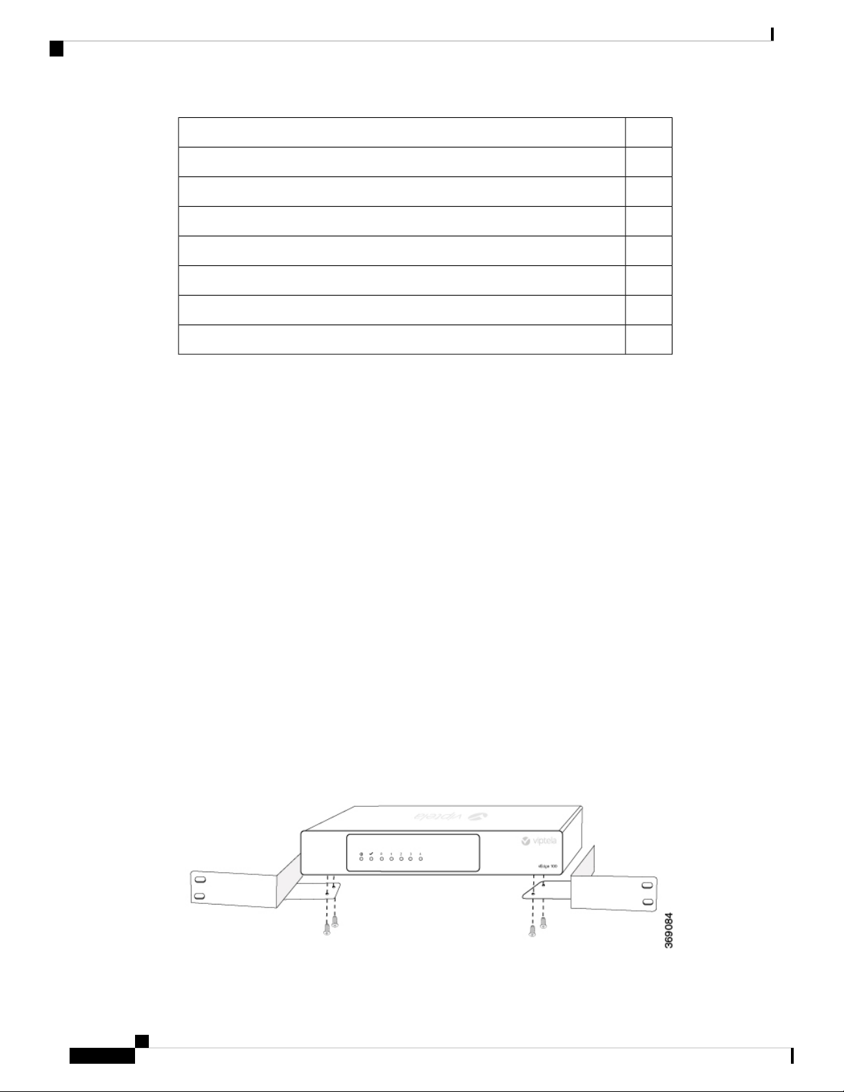
3. Secure the left and right mounting ears to either side of the router chassis using the four screws (two on
each side) in the packet marked A.
Figure 2: Attaching the Mounting Ears to the vEdge 100 Router Chassis
Hardware Installation Guide for vEdge Routers
12
Page 19
vEdge 100 Router
Install the vEdge 100 Router
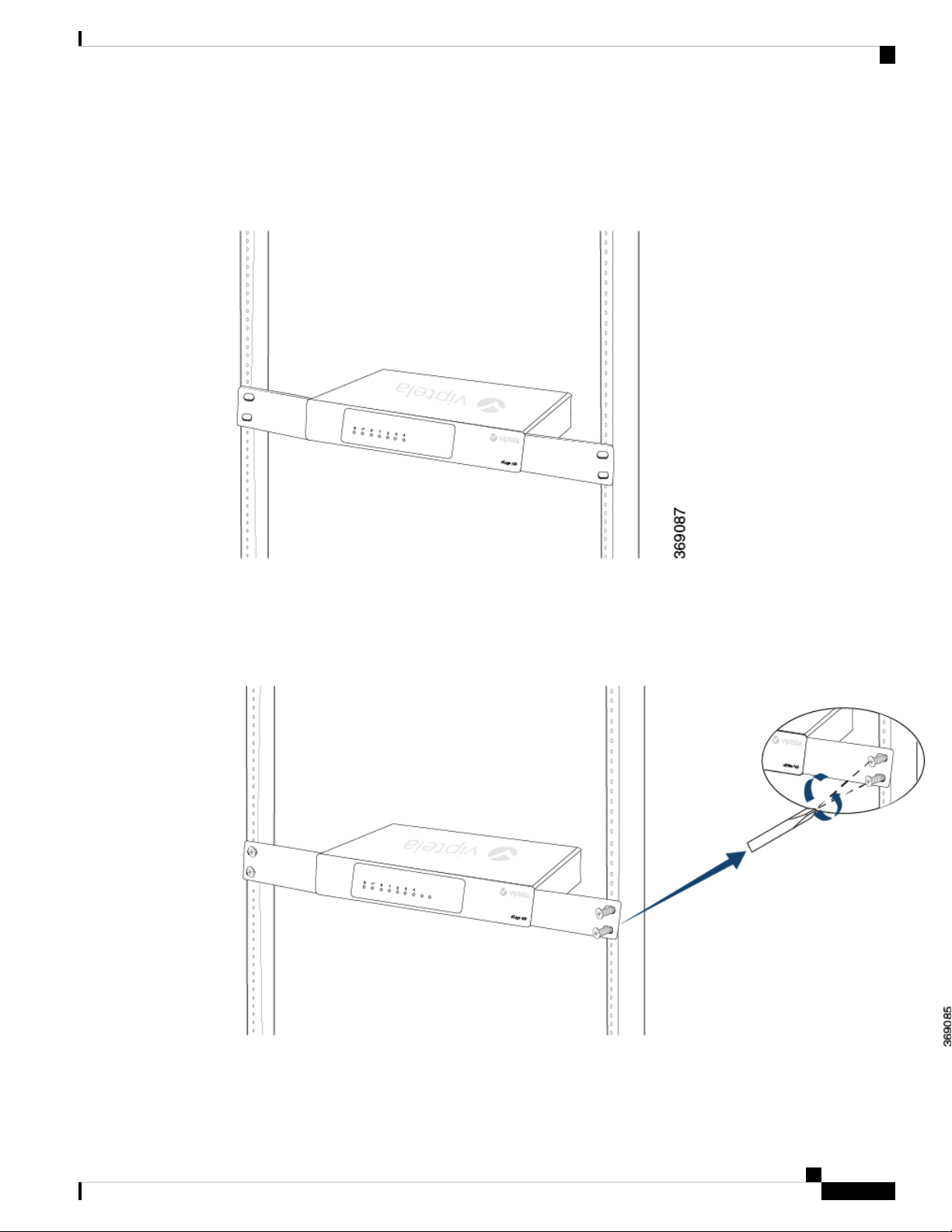
1. Grasp both sides of the router, then lift and position it in the rack, making sure that the mounting ear holes
are aligned with the threaded holes in the rack rail.
Figure 3: Positioning the vEdge 100 Router in the Rack
1. Secure the mounting ears to the two front posts of the rack using the four rack-mount screws (two on each
side) in the packet marked B. Tighten the screws.
Figure 4: Attaching the Mounting Ears to the Rack
1. Use a tape measure or level to verify that the tray is installed straight and the holes at either ends of the
rack align properly.
Hardware Installation Guide for vEdge Routers
13
Page 20
Install the vEdge 100 Router
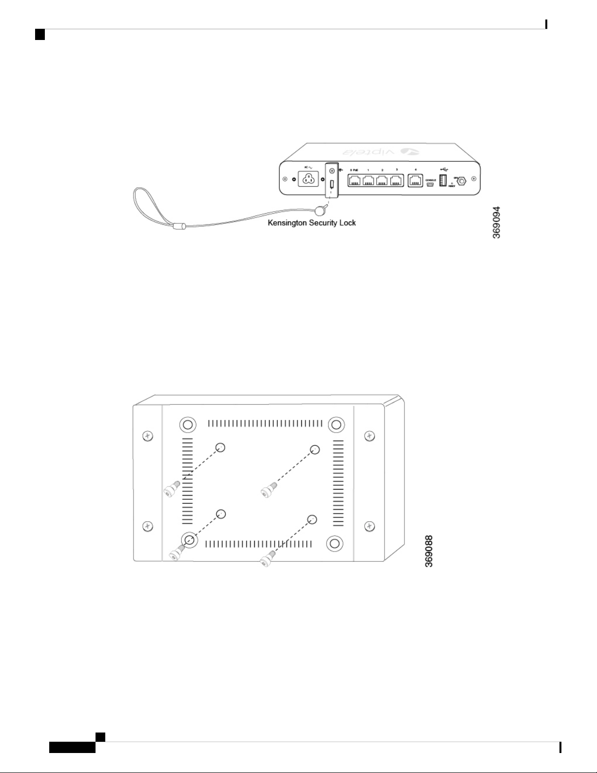
2. Secure the router with a Kensington lock. To do so, first attach the lock plate from packet C to the back
Figure 5: Securing the Router with a Kensington Lock
Tip: It is recommended that you retain the dust covers on any unused ports.
Mount the vEdge 100 Router on the Wall
To mount the vEdge 100 router on the wall:
vEdge 100 Router
of the chassis, then insert the lock in the slot.
1. Screw the four shoulder screws in the packet marked D into the pre-drilled holes on the underside of the
router chassis as shown in Figure 6. Tighten the screws until wrist tight. Note that the screw heads will
not be flush with the chassis bottom.
Figure 6: Attach Screws to the Underside of the vEdge 100 Router Chassis
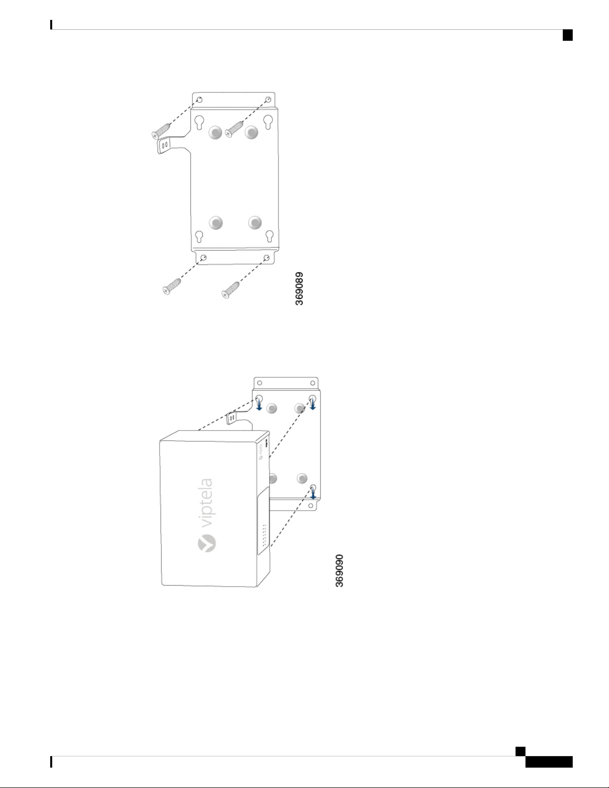
1. Secure the mounting plate to the wall using four screws appropriate for your wall type (screws not included).
Ensure that the L-shaped bracket of the mounting plate is to the upper left.
Figure 7: Securing the Mounting Plate to the Wall
Hardware Installation Guide for vEdge Routers
14
Page 21
vEdge 100 Router
Install the vEdge 100 Router
1. Mount the router on the mounting plate by aligning the four screws on the underside of the router chassis
to the holes in the mounting plate. Then gently slide the router chassis into the slots.
Figure 8: Mounting the vEdge 100 Router on the Mounting Plate
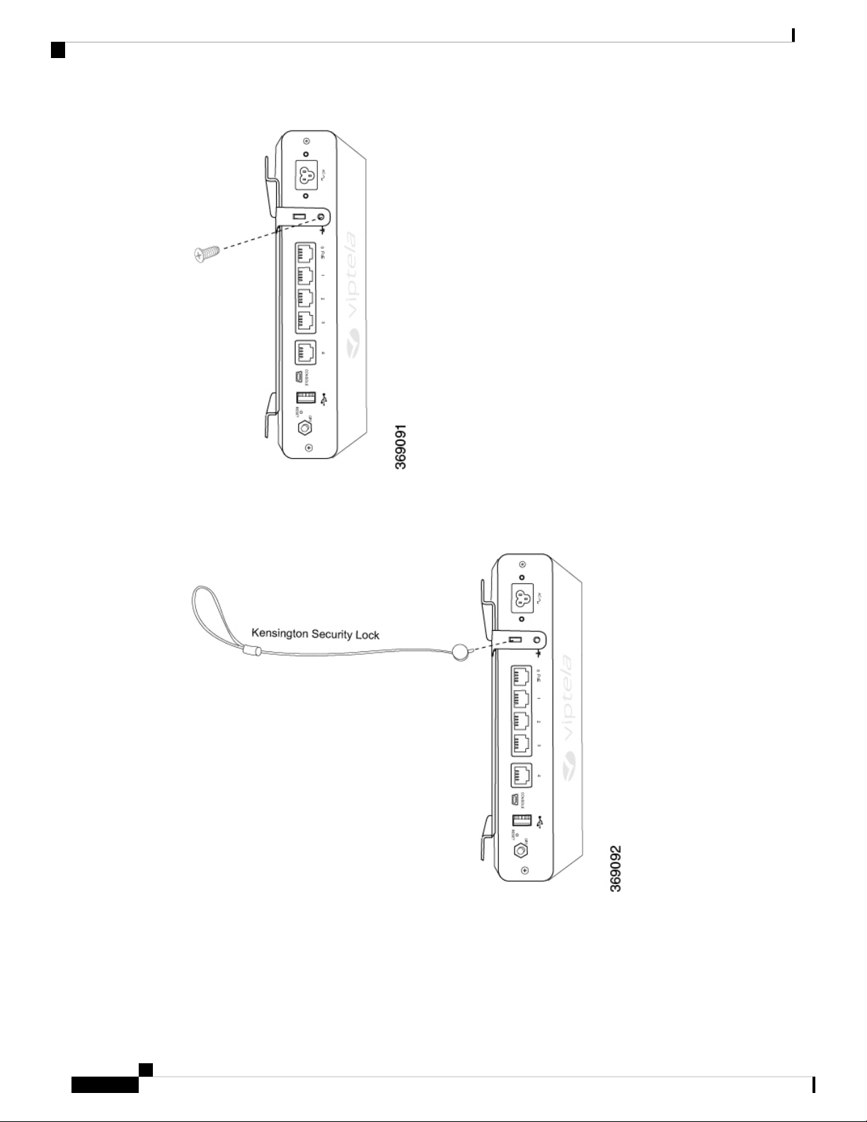
1. Secure the router by aligning the round hole on the L-shaped bracket of the mounting plate with the screw
hole in the rear of the router chassis. Then attach the L-shaped bracket to the router using a mounting ear
screw from packet A.
Figure 9: Securing the vEdge 100 Router to the Mounting Plate
Hardware Installation Guide for vEdge Routers
15
Page 22
Connect the vEdge 100 Router
vEdge 100 Router
1. Secure the router with a Kensington security lock using the slot in the rear of the chassis.
Figure 10: Securing the Router with a Kensington Security Lock
Connect the vEdge 100 Router
This article describes how to connect the vEdge 100 router to an AC power source and to a management
console.
Hardware Installation Guide for vEdge Routers
16
Page 23
vEdge 100 Router
Connect the vEdge 100 Router
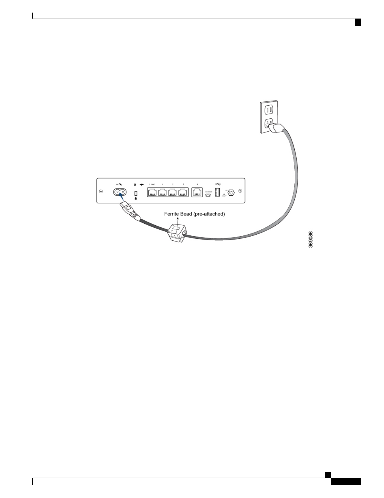
Connect AC Power to the Router
To connect the vEdge 100 router to an AC power source, plug one end of the AC power cord into the back
of the router, and plug the other end into an AC power outlet as shown in Figure 1.
Figure 1: Connecting AC Power Supply to a vEdge 100 Router
Note: It is strongly recommended that you use the power cord supplied with the vEdge 100 router.
Caution: If you are connecting AC power to the router, it is recommended that the building have an external
surge protective device installed.
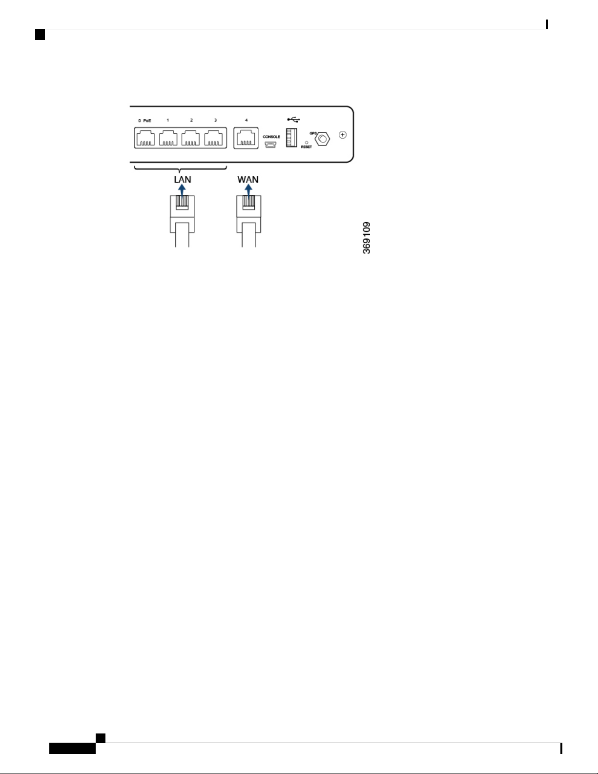
Connect the Router to LAN and WAN Interfaces
To connect the vEdge 100 router to the LAN, plug the appropriate cable into any port, except port 4, on the
front of the router.
To connect the vEdge 100 router to a WAN, plug the appropriate cable into port 4 on the front of the router.
Figure 2: Connecting a vEdge 100 Router to LAN and WAN Interfaces
Hardware Installation Guide for vEdge Routers
17
Page 24
Connect the vEdge 100 Router
Connect the Router to a Management Console
To connect the vEdge 100 router to a management console:
vEdge 100 Router
1. Connect one end of the USB Type-A to Mini-B connector cable into the console port, labeled CONSOLE,
on the vEdge router.
2. Connect the other end of the console cable into the console server or to a management console.
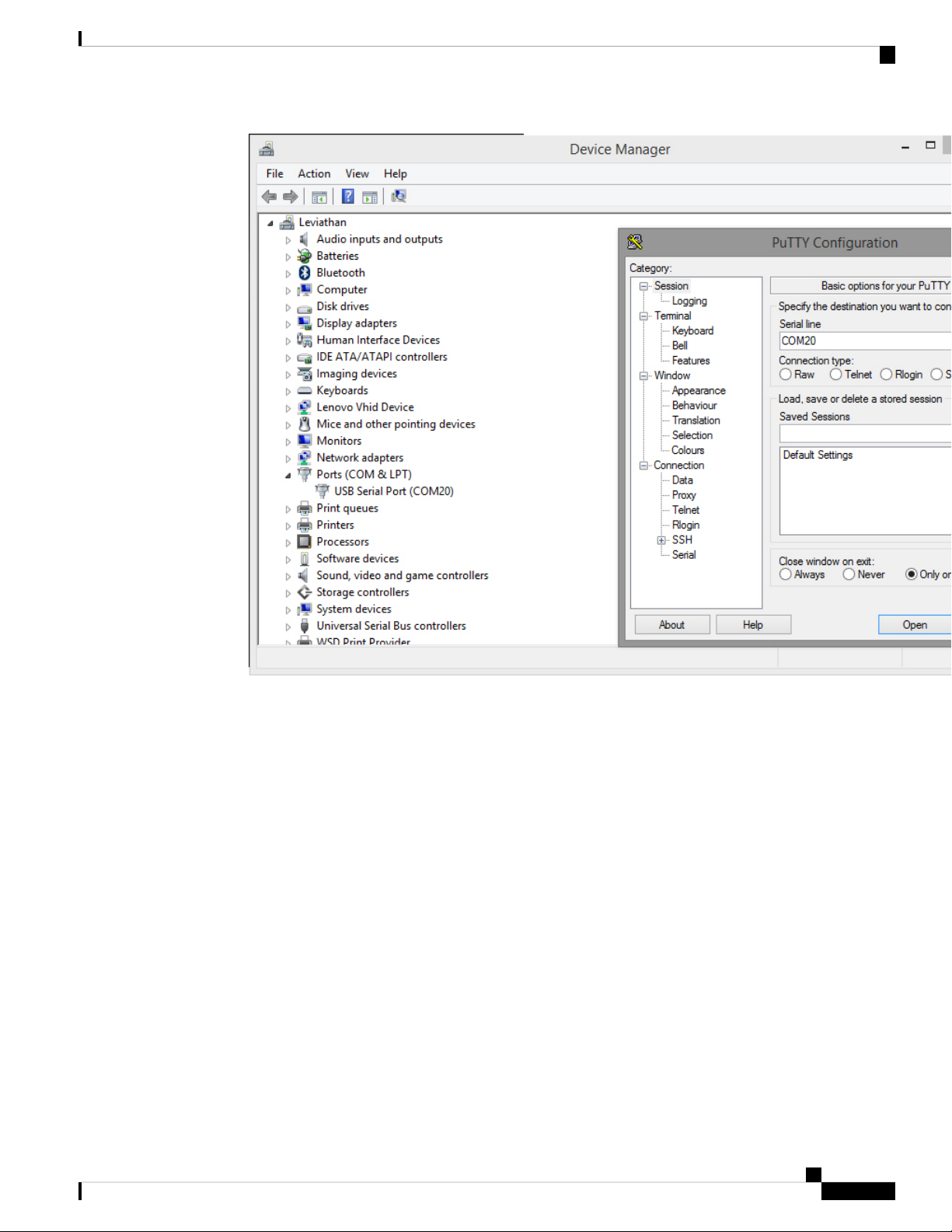
To use the USB console from a Windows device:
1. Go to the Device Manager to determine which COM port is being used for the USB serial port.
2. In the PuTTY SSH/Telnet client, in Connection Type, select Serial. Then, specify the COM port and a
speed of 115200.
Hardware Installation Guide for vEdge Routers
18
Page 25
vEdge 100 Router
vEdge 100 Router Default Configuration
You can download the Windows driver here .
To use the USB console from a Macintosh device:
1. Install the USB serial drivers attached here .
2. Launch the Terminal utility.
3. From a terminal shell, access the console port with this command:
$ screen /dev/tty.usbserial* 115200,cs8
vEdge 100 Router Default Configuration
The default configuration file looks like this:
vEdge100# show running-config
system
vbond ztp.viptela.com
aaa
auth-order local radius tacacs
usergroup basic
task system read write
task interface read write
Hardware Installation Guide for vEdge Routers
19
Page 26

Maintenance and Troubleshooting
!
usergroup netadmin
!
usergroup operator
task system read
task interface read
task policy read
task routing read
task security read
!
user admin
password
$6$qtmMiZWj6W6Kh3nr$<wbr/>MAyIfWUVDPDP2q04LqhdIi6kSXySX7<wbr/>fudpwNOg1.<wbr/>6e4XgpKwwNMkV7gx69O4WWtnvLnUg8<wbr/>aoUGw972PHMNati1
!
!
logging
disk
enable
!
!
!
omp
no shutdown
graceful-restart
advertise connected
advertise static
!
security
ipsec
authentication-type ah-sha1-hmac sha1-hmac
!
!
vpn 0
interface ge0/4
ip dhcp-client
tunnel-interface
encapsulation ipsec
allow-service dhcp
allow-service dns
allow-service icmp
no allow-service sshd
no allow-service ntp
no allow-service stun
!
no shutdown
!
!
vpn 512
!
vEdge 100 Router
Maintenance and Troubleshooting
Now that you have installed and connected the vEdge 100 router, you can monitor and troubleshoot the various
LEDs and system alarms on the router.
Alarm Severity Levels
The system alarms on the vEdge 100 router have two types of severity levels:
• Major (red)—Indicates a critical situation on the router resulting from one of two conditions:
Hardware Installation Guide for vEdge Routers
20
Page 27
vEdge 100 Router
Maintenance and Troubleshooting
One or more hardware components on the router has failed.•
• One or more hardware components on the router has exceeded the temperature threshold.
A major alarm condition requires immediate attention. If a temperature related major alarm persists for more
than five minutes, the router will shut down.
• Minor (yellow)—Indicates a warning on the router that, if left unattended, might result in an interruption
in router operation or degradation in router performance. A yellow alarm condition requires further
monitoring and/or maintenance.
Hardware Alarms
Hardware alarms on the vEdge 100 router are predefined and are triggered by a physical condition on the
router such as a power supply failure, excessive component temperature, or fan failure. The vEdge 100 router
triggers the following types of hardware alarms:
• Main board temperature alarm—The main board of the router has one temperature sensing point (board
sensor 0). If the temperature of the sensor location crosses the predefined threshold level, the system
triggers an alarm.
• CPU temperature alarm—If the temperature of the system CPU crosses the predefined threshold level,
the system triggers an alarm.
• Fan alarm—The router has a fixed built-in fan for system cooling which runs at a fixed speed. If the fan
stops running, the system triggers an alarm. Also if the fan starts to run below a predefined RPM threshold,
the system triggers an alarm.
Table 1 lists the yellow and red alarm threshold for the temperature sensing points in the system—one board
sensor on the board and one CPU junction temperature sensor. The lower threshold value (Bad Fan) applies
if a fan failure condition is also detected; otherwise the higher threshold value applies (normal).
Table 7:
Item
Yellow Alarm(degrees
C)
Red Alarm(degrees
C)
Bad FanNormalBad FanNormal
75806065Board sensor 0
90957580CPU junction
temperature
Checking Alarms and Notifications
To view the current chassis environment condition , enter the show hardware environment command at
the system prompt. The system displays the power supply status, temperature sensor readings, fan speed, and
related alarm status if any exists.
To view the severity of active alarms, enter the show hardware alarms command at the system prompt. The
system displays the alarm severity and a brief description of the cause of each active alarm.
Hardware Installation Guide for vEdge Routers
21
Page 28

Restore a vEdge Router
vEdge 100 Router
To view temperature thresholds at which green, yellow, and red alarms are generated, enter the show hardware
temperature-thresholds command at the system prompt. The system displays the alarm temperature threshold
information for a specific board or all boards in the router and for the router's CPU.
To view all other events on a Viptela device, enter the show notification stream command. The system
displays notifications about events that have occurred on the Viptela device.
LEDs
The chassis LEDs located on the front panel of the vEdge 100 router indicate the status of the router.
If there are one or more major alarms active in the router, the Status LED is lit red. If there are one or more
minor alarms active in the router, the Status LED is lit solid yellow. See Front and Rear Panel Components
for details of the LEDs and the status they indicate.
Additional Information
show hardware alarms show hardware environment show notification stream show hardware
temperature-thresholds Front and Rear Panel Components Check Alarms and Events
Restore a vEdge Router
This article explains how to revert the configuration for a vEdge router to the factory-default values. It also
explains how to do a soft and hard reset of the router.
Reverting to the vEdge Router Factory-Default Configuration
After you set up and start the virtual machines (VMs) for the vEdge Cloud routers and set up and start the
hardware vEdge routers in your overlay network, they come up with a factory-default configuration . When
you make and commit changes to the default configuration, a new configuration file is created. This new
configuration file then becomes the active configuration.
If desired, you can revert to the default factory configuration:
vEdge# request software reset
Reset the Router
You can reset the vEdge router by doing either a hard press or a soft press. To perform either type of press,
locate the Reset button on the front panel of the router. The Reset button is recessed to avoid accidentally
pressing it while the router is operational. To press the Reset button, use a sharp narrow tool.
Perform a Long Press Reset
A long press reset of the vEdge router erases passwords, keys, and most other configuration parameters,
restoring the router to its factory-default configuration.
To perform a long press reset, press the Reset button for more than 10 seconds. After you release the Reset
button, the router will reboot and resume normal operation.
Perform a Short Press Reset
A short press reset of the Edge router is equivalent to a graceful software reboot and is the same as entering
the reboot command at the CLI prompt.
Hardware Installation Guide for vEdge Routers
22
Page 29
vEdge 100 Router
To perform a short press reset, press the Reset button for two seconds. The short press reset takes effect almost
instantaneously and reboots the router.
Return Hardware
This article describes how to return a vEdge router or a hardware component to Viptela for repair or replacement.
Locate Serial and Model Number
To return a vEdge router or a hardware component to Viptela, you need the serial and model number of the
router or the component being returned.
You can locate the serial and model number of a vEdge router in one of the following ways:
• In vManage NMS, select the Configuration ► Devices screen. The device table lists the serial and model
• Enter the show hardware inventory command at the CLI prompt.
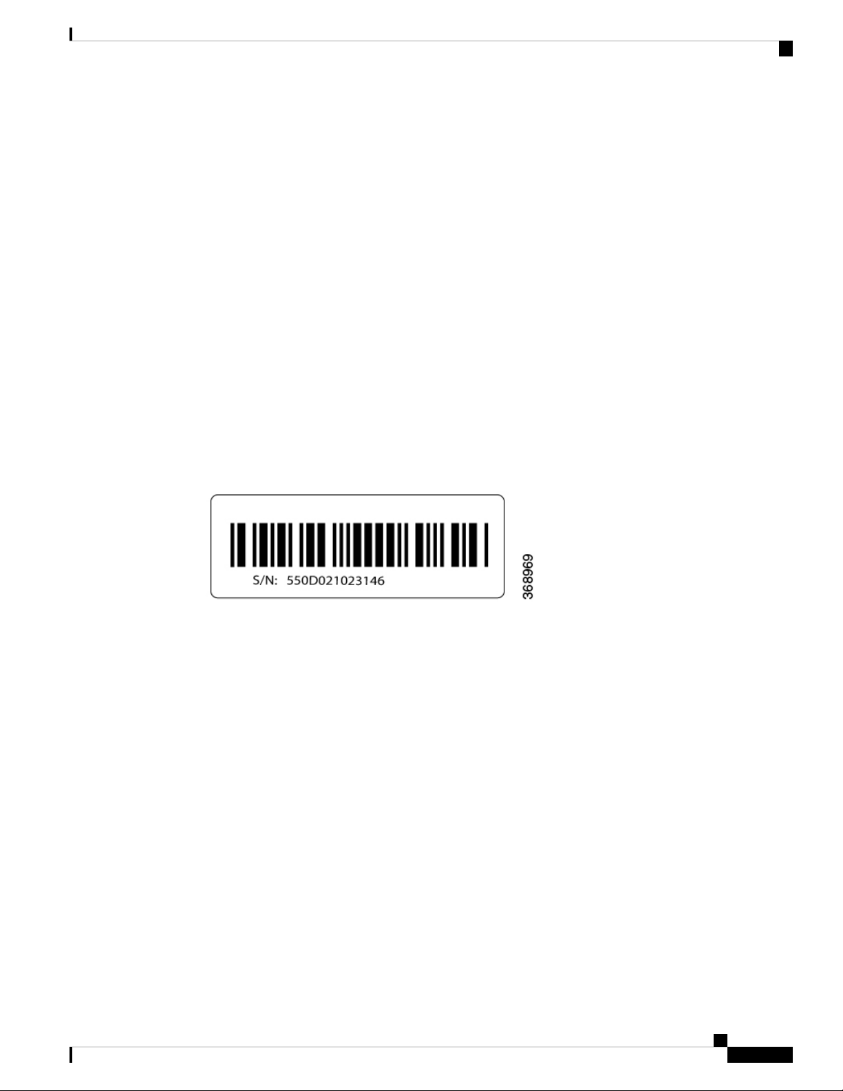
• The serial number (sample shown in Figure 1) is printed on a label on the right side of the router; the
Return Hardware
numbers of the routers in the network.
model number is printed on a label on the back of the router.
Figure 1: Sample Serial Number Label for a vEdge Router
Obtain an RMA Number
If you are returning a vEdge router or a hardware component to Viptela for repair or replacement, contact the
Viptela Customer Support team to open a support case and obtain a Return Materials Authorization (RMA)
number.
Before you open a case and request an RMA number, keep the following information ready:
• Your existing service contract number, if you have one
• Serial number of the router or component
• Model number of the router or component
• Physical location of the router
• Your name, organization name, telephone number, fax number, and shipping address
• Failure or problem description with details
• Type of activity being performed on the router when the problem occurred
• Configuration data displayed by one or more show commands
To obtain an RMA number:
Hardware Installation Guide for vEdge Routers
23
Page 30

Return Hardware
vEdge 100 Router
1. Open a support case with Viptela in one of the following ways:
• Log in to www.viptela.com/support
• Send email to support@viptela.com
• Call toll-free 800-525-5033
1. A Viptela Customer Support representative validates your request and issues an RMA number for returning
the router or a hardware component.
Note: Do not return the router or any component to Viptela before first obtaining an RMA number. Viptela
reserves the right to refuse to take any shipment that does not have an RMA number.
Repack the Router
If you need to move or return the vEdge router, repack the router in its original packing. Before you repack
the router follow these steps:
1. Shut down the vEdge router by issuing the poweroff command at the CLI prompt.
2. Disconnect power to the router.
3. Remove the cables and transceivers.
You will need the following tools to repack the router:
• Phillips Number 2 (+) screwdriver
• Cardboard carton and original packing in which you received the router
To repack the router in its original packing:
1. If you do not have a vEdge 1000 router, skip this step. Otherwise:
1. If the router is installed in a rack using the rack-mount kit from Viptela, remove the front stopper
screwed along the front side of the rack-mount tray.
2. Then remove the rack-mount tray from the rack by having one person support the weight of the
rack-mount tray while a second person unscrews the rack-mount screws.
3. Place the rack-mount tray on a firm, flat surface.
4. Slide out the vEdge 1000 router from the rack-mount tray.
2. Place the router chassis in the plastic packing bag.
3. Place the side packing foam on both sides of the router chassis.
4. Secure the chassis in the cardboard carton.
5. Secure the top of the chassis by placing the top packing foam over the top of the chassis.
6. Close the cardboard shipping box and seal it with packing tape.
7. Write the RMA number on top of the box for purposes of tracking.
Hardware Installation Guide for vEdge Routers
24
Page 31

vEdge 100 Router
Return Hardware
If you are returning any field-replaceable units with the router, repack them as described in Repack Router
Components below.
Repack Router Components
If you need to return any router components, follow these steps:
1. Ensure that you have the antistatic bag for each component and an ESD grounding strap.
2. Place each component in its antistatic bag.
3. Pack each component in its original packing material. If you do not have the original packing material,
ensure that the component is packed adequately with packing material to prevent any damage in transit.
4. Place the component in the original cardboard box or another cardboard box if the original is not available.
5. Secure the box with tape.
6. Write the RMA number on top of the box for purposes of tracking.
Hardware Installation Guide for vEdge Routers
25
Page 32

Return Hardware
vEdge 100 Router
Hardware Installation Guide for vEdge Routers
26
Page 33

CHAPTER 2
vEdge 100b Router
The vEdge 100b router delivers highly secure site-to-site data connectivity to small business and home offices
(SOHO). The vEdge 100b router is a fixed-port-configuration router with the following features:
• Five built-in 10/100/1000 Mbps Ethernet ports
• Encryption and QoS support
• 100 Mbps forwarding throughput (inclusive of encryption)
• Secure identification chip for anti-counterfeit and secure authentication
• External power supply
• Kensington security lock slot to physically lock down the router
• Desktop mount, wall mount, or rack-mountable in a 19-inch rack
• Fanless design
Chassis Views
Figure 1 and Figure 2 show the front and back panels of the vEdge 100b router, indicating the location of the
power interfaces, status indicators, and chassis identification labels.
Figure 1: Front Panel of the vEdge 100b Router
Hardware Installation Guide for vEdge Routers
27
Page 34

Declaration of Conformity
vEdge 100b Router
Figure 2: Back Panel of the vEdge 100b Router
• Declaration of Conformity, on page 28
• Components and Specifications, on page 29
• Planning and Installation, on page 34
• Maintenance and Troubleshooting, on page 46
Declaration of Conformity
The Viptela products are controlled under the Commerce Control List (CCL) of the U.S. Export Administration
Regulations (EAR) as networking equipment within the following U.S. Export Control Classification Numbers
(ECCN): 5A002, 5D002, and 5E002.
The vEdge hardware and software products and the Viptela encryption technology can be delivered to most
end users and destinations worldwide without a licensing requirement. The Viptela solution and products
Hardware Installation Guide for vEdge Routers
28
Page 35

vEdge 100b Router
Components and Specifications
have undergone a one-time review by the Government of the United States of America and qualify for License
Exception ENC. As such, they are eligible for export according to Section 740.17 of the EAR.
The Viptela solutions and products can be delivered to most end users worldwide, except to entities or end
users in the following countries: Cuba, Iran, North Korea, Sudan, and Syria.
Controlled Technologies
Viptela manages technology subject to the U.S. Export Administration Regulations (EAR). These controlled
technologies may include items under U.S. ECCN 5E002 encryption technology. The Viptela encryption
technology is for the development, production, and use of Viptela products that implement or use encryption.
The Viptela software distribution policy allows only authenticated users to download the Viptela encryption
software. Recipients of controlled technology are obliged to maintain adequate controls to prevent nationals
from outside the U.S. and Canada from accessing Viptela information, subject to ECCN5E002, without first
obtaining authorization from the U.S. government.
For additional information on controlled technologies, please contact Viptela support at support@viptela.com
.
Components and Specifications
This article provides the chassis specifications of the vEdge 100b router and lists the other router components.
Chassis Specifications
Table 1 lists the specifications for the vEdge 100b router chassis.
Table 8:
Services and Slot Density
RJ45 Ports 10/100/1000 Mbps
(IPSec)
rate 115.2 Kbps)
Power supply
SpecificationItem
5 ports
YesEmbedded hardware-based crypto acceleration
2 GBMemory DDR3 ECC DRAM
4 GBNAND storage (internal)
1Mini USB connector console port (default baud
12 Volt DC Input
Power Specifications
AC input voltage
External AC-DC power adapter provided
90-264 Vrms
47-63 HzAC input line frequency
Hardware Installation Guide for vEdge Routers
29
Page 36

Components and Specifications
Physical Specifications
vEdge 100b Router
SpecificationItem
15 WattsTypical power consumption
Chassis height
Packaging Specifications
Package height
Operating Condition
Temperature
1.75 in. (4.4 cm)
6.75 in. (17 cm)Chassis width
5.5 in. (14 cm)Chassis depth
Can be accommodated in 1 RURack height
1.75 lb (0.79 kg)Chassis weight
Provided with the unitRack-mount accessory kit 19 in (48.3 cm) EIA
3.58 in. (9.09 cm)
7.75 in. (19.68 cm)Package width
13 in. (33 cm)Package depth
Fanless design
0 to 40°C (32 to 104°F) at sea level ( temperature
de-rating of 1.5 deg C per 1000 feet of altitude
applicable up to max of 10000 feet or 3000 m)
Transportation/Storage Condition
Temperature
Reliability
MTBF
Regulatory Compliance
Safety
EMC
Max 3000 m (10000 ft)Altitude
10 to 85% RHHumidity
-40 to 70°C (-40 to 158°F)
5 to 95%RHHumidity
4570 m (15000 ft)Altitude
Approximately 592,000 hours (about 67 years)
AS/NZS 60950-1 CAN/CSA 60950-1 CB-IEC60950-1
CE Marking EN 60950-1 UL60950-1
AS/NZS CISPR22 Class A EN 300 386 EN 55022
Class A FCC Class A ICES Class A VCCI Class A
Hardware Installation Guide for vEdge Routers
30
Page 37

vEdge 100b Router
Front and Rear Panel Components
This article describes the components on the front and rear panels of the vEdge 100b router.
Front Panel
The front panel of the vEdge 100b router has the DC power socket, chassis status LEDs, and reset button. See
Chassis Views for the location of these components.
DC Power Socket
The front panel of the vEdge 100b router has a DC power input socket for plugging in the external 12-Volt
AC-DC power adapter that is shipped with the router.
Front and Rear Panel Components
SpecificationItem
ROHS 6/6Environmental
Chassis Status LEDs
The vEdge 100b router has a power LED, a status LED, and Ethernet port LEDs located in the front panel.
Each RJ-45 port has two built-in LEDs. See Figure 1.
Figure 1: Chassis Status LEDs in a vEdge 100b Router
Table 1 describes the LEDs , their color and states, and the status they indicate.
Hardware Installation Guide for vEdge Routers
31
Page 38

Front and Rear Panel Components
Table 9:
vEdge 100b Router
StatusColorLED
LEDs (0–4)
LEDs (0–4)
Green/RedPower
• Off: System is not on
• Green: System is powered on
• Red: Power supply fault
Green/Yellow/RedStatus (SYS)
• Off: System is not on
• Solid Green: System is fully functional and OMP connection
is in the Up state
• Blinking Green: System is booting up
• Solid Yellow: System is up but OMP connection is in the
Down state
• Solid Red: System has detected a major system level
fault—one of the necessary daemons in the system is
down (system will usually reboot shortly after this)
GreenRJ-45 Ethernet Port
• Off: No link and corresponding yellow LED is off
• Solid Green: 1000 Mbps link detected
• Blinking Green: 1000 Mbps link detected and link activity
YellowRJ-45 Ethernet Port
• Off: No link and corresponding green LED is off
• Solid Yellow: 10/100 Mbps link detected
• Blinking Yellow: 10/100 Mbps link detected and link activity
Reset Button
The Reset button on the front panel is recessed, to avoid accidentally pressing it while the router is operational.
To press the Reset button, use a sharp narrow tool. Table 2 describes the effects of pressing the Reset button.
Table 10:
BehaviorPress
Duration
Pressing for two seconds resets and reboots the router.Short press
Pressing for 10 seconds resets the router and reboots it with factory default configuration.Long press
Rear Panel
The rear panel of the vEdge 100b router has a small metal-enforced hole for attaching a Kensington lock to
secure the router. See Chassis Views for the location of these components.
Hardware Installation Guide for vEdge Routers
32
Page 39
vEdge 100b Router
Ports and Connectors
The vEdge 100b router supports two types of interface ports: RJ-45 Ethernet ports and USB serial console
port.
RJ-45 Ethernet Ports
There are five built-in RJ-45 Ethernet ports on the vEdge 100b router. These ports support 10/100/1000 Mbps
and are numbered 0 through 4.
Figure 1 provides the pinout information for the RJ-45 ports. The RJ-45 ports comply with the 801 standards.
Figure 1: RJ-45 Ports Pinout Information
Ports and Connectors
Power Supply
Console Port
The console port on the vEdge 100b router is a serial port and is accessible via a USB Mini-B connector. See
Figure 2.
Figure 2: USB Mini-B Connector
A USB Type-A to Mini-B connector cable is shipped with the vEdge 100b router as standard accessory for
console port connection.
The vEdge 100b router has an external power supply and ships with a 12-Volt AC-DC power adapter.
AC-DC Power Adapter
The vEdge 100b router accepts a DC power input of 12 Volts. You can power the router by plugging one end
of the AC power adapter into the front of the router, and the other end into an AC power outlet.
The AC-DC power adapter has the following wall-connector options:
• Type A (commonly used for Canada, Japan, Mexico, and US)
Hardware Installation Guide for vEdge Routers
33
Page 40

Planning and Installation
vEdge 100b Router
• Type C (commonly used for Asia, Europe, and South America)
• Type G (commonly used for Ireland, Malaysia, Singapore, and United Kingdom)
• Type I (commonly used for Argentina, Australia, China, and New Zealand)
Table 1 describes the AC power supply specifications for the vEdge 100b router.
Table 11:
SpecificationItem
AC input voltage
consumption
Planning and Installation
This article provides general safety standards to adhere to when installing or connecting a vEdge 100b router
or its components.
General Safety Standards
• Install your vEdge router in compliance with the following local, national, and international electrical
codes:
• United States—National Fire Protection Association (NFPA 70), United States National Electrical
Code.
• Other countries—International Electromechanical Commission (IEC) 60364, Part 1 through Part
7.
• Evaluated to the TN power system.
90-264
Vrms
47-63 HzAC input line frequency
15 WattsTypical power
• Canada—Canadian Electrical Code, Part 1, CSA C22.1.
• Locate the emergency power-off switch in the room in which you are working. In case of an electrical
accident, quickly turn off the power.
• Disconnect power before installing or removing the router.
• If an electrical accident occurs, use caution and immediately turn off power to the router.
• Make sure that grounding surfaces are thoroughly cleaned and well-finished before grounding connections
are made.
• Do not work alone if hazardous conditions exist.
• Always check that power is disconnected from a circuit. Never assume that it is disconnected.
Hardware Installation Guide for vEdge Routers
34
Page 41

vEdge 100b Router
• Carefully inspect your work area for possible hazards, such as moist floors, worn-out power cords,
ungrounded power extension cords, and missing safety grounds.
• Operate the device within marked electrical ratings and product usage instructions.
• To ensure that the router and the FRUs function safely and correctly, use the specified cables and
connectors, and make certain they are in good condition.
Prepare for Router Installation
This article provide guidelines and requirements for preparing your site to install the vEdge 100b router.
Site Preparation Guidelines
Efficient operation of your vEdge 100b router requires proper site planning and proper layout of your equipment
rack or wiring closet:
• Ensure that the area around the router is kept free of dust and conductive material.
• Follow appropriate airflow guidelines so that the cooling system functions normally.
Prepare for Router Installation
• Follow ESD prevention procedures to avoid any damage to the router.
• Install the router in an enclosed, secure area allowing only authorized personnel to access the device.
Environmental Requirements
Install the vEdge 100b router in a dry, clean, temperature-controlled, and well-ventilated environment:
• Maintain ambient airflow for the router to operate normally. The ambient intake air temperature should
be in the range 0°C to 40°C (32°F to 104°F). If the airflow is blocked or if the air intake is too warm,
the router can get overheated.
• Avoid temperature extremes. Ensure that the router is operating at an ambient temperature not more that
40°C (104°F) at sea level. For higher altitudes, a derating of 1.50°C per 1,000 feet applies.
• High humidity conditions can cause moisture to penetrate into the chassis. The device supports 10% to
85% humidity levels, non-condensing.
Rack Requirements
You can mount the vEdge 100b router in a two-post or a four-post rack. Table 1 provides the rack requirements
for the router.
Table 12:
GuidelinesRack Requirement
Rack type
Mounting brackets
Use a two-post or a four-post rack that meets the size requirements for the router,
provides bracket holes or hole patterns spaced at 1 U (1.75 in. or 4.45 cm)
increments, and is strong enough to support the weight of the router.
Ensure that the holes in the mounting brackets are spaced at 1 U (1.75 in. or 4.45
cm). This allows you to mount the router in any location in the rack.
Hardware Installation Guide for vEdge Routers
35
Page 42

Install the vEdge 100b Router
vEdge 100b Router
GuidelinesRack Requirement
Rack size
building structure
Install the vEdge 100b Router
Once you have prepared your site for router installation, unpack the vEdge 100b router and mount it either
on the wall or in a 19-inch rack.
Unpack the vEdge 100b Router
A vEdge 100b router is shipped in a cardboard carton and secured firmly in place with foam packing material.
The carton contains a packing list and Quick Start instructions. It is recommended that you do not unpack the
router till you are ready to install it.
To unpack the router:
It is recommended that the rack comply with the size and strength standards of a
19-inch rack as defined in Cabinets, Racks, Panels, and Associated Equipment
(document number EIA-310–D), published by the Electronics Industry Association
http://www.eia.org . Ensure that the rack rails are spaced widely enough to
accommodate the external dimensions of the chassis and that the outer edges of
the front mount brackets extend the width of the chassis to 19 in. (48.2 cm). You
must also ensure that the spacing of rails and adjacent racks allows for the proper
clearance around the router and rack.
For maximum stability, secure the rack to ceiling brackets and to floor brackets.Rack secured to
1. Open the top flaps of the carton.
2. Gradually remove the packing foam holding the router and the accessories in place. See Figure 1.
3. Take out the router and each accessory.
4. Verify the router components against the packing list included in the box (see packing list below).
Figure 1: Unpacking the vEdge 100b Router
Hardware Installation Guide for vEdge Routers
36
Page 43

vEdge 100b Router
Install the vEdge 100b Router
Note: It is recommended that you do not discard the shipping carton and packing material when you unpack
the router. Flatten and store the box in case you need to move or return the router in the future. See Return
Hardware.
Packing List for a vEdge 100b Router
The cardboard carton in which the router is packed includes a packing list. Check the parts you receive with
your router against the items on the packing list. The packing list specifies the part number, name, and quantity
of each item in the carton.
If any part on the packing list is missing, contact your customer service representative or contact Viptela
customer support from within the U.S. or Canada by telephone at 800-525-5033 or by email to
support@viptela.com .
Table 1 lists the parts shipped with the vEdge 100b router and their quantities.
Table 13:
QuantityComponent
1Router chassis
Hardware Installation Guide for vEdge Routers
37
Page 44

Install the vEdge 100b Router
Mount the vEdge 100b Router
You can mount the vEdge 100b router in one of the following ways:
vEdge 100b Router
QuantityComponent
1USB console cable
2Mounting ears, left and right
6Mounting-ear screws (Packet A)
4Rack-mount screws (Packet B)
1 + 4AC power adapter and connectors
1Quick Start document
• Mount the router in a 19-inch rack
• Mount the router on the wall
In addition to the accessory box, you need the following tools to mount a vEdge 100b router:
• Number 2 Phillips (+) screwdriver
• Tape measure or level
Mount the vEdge 100b Router in a Rack
You can mount the vEdge 100b router on two front posts in a 19-inch rack using simple rack mount ear
accessories. To do so:
1. Place the router chassis on the floor or on a sturdy table near the rack.
2. Verify the internal dimensions of the rack with a tape measure. The rack-mount tray is 440 mm wide and
must fit within the mounting posts.
3. Secure the left and right mounting ears to either side of the router chassis using the six screws (two on
each side) in the packet marked A.
Figure 2: Attaching the Mounting Ears to the vEdge 100b Router Chassis
1. Grasp both sides of the router, then lift and position it in the rack, making sure that the mounting ear holes
are aligned with the threaded holes in the rack rail.
Hardware Installation Guide for vEdge Routers
38
Page 45

vEdge 100b Router
Install the vEdge 100b Router
Figure 3: Positioning the vEdge 100b Router in the Rack
1. Secure the mounting ears to the two front posts of the rack using the four rack-mount screws (two on each
side) in the packet marked B. Tighten the screws.
Figure 4: Attaching the Mounting Ears to the Rack
1. Use a tape measure or level to verify that the tray is installed straight and the holes at either ends of the
rack align properly.
Hardware Installation Guide for vEdge Routers
39
Page 46

Connect the vEdge 100b Router
Tip: It is recommended that you retain the dust covers on any unused ports.
Mount the vEdge 100b Router on the Wall
You can mount the vEdge 100b router on the wall either horizontally or vertically.
To mount the vEdge 100b router on the wall:
1. Measure the distance between the two wall-mount holes on the underside of the router chassis as shown
in Figure 5.
Figure 5: Measuring the Distance Between the Wall-Mount Holes
vEdge 100b Router
1. Insert two wall-mount screws in the wall where you are mounting the router (screws not provided). The
screws must align with the wall-mount holes on the router's underside.
2. Align the wall-mount holes on the router's underside to the screws in the wall, and gently slide the chassis,
from side to side or up and down, onto the wall-mount screws.
Figure 6: Sliding the Router Chassis onto the Wall-Mount Screws
Connect the vEdge 100b Router
This article describes how to connect the vEdge 100b router to an AC power source and to a management
console.
Hardware Installation Guide for vEdge Routers
40
Page 47

vEdge 100b Router
Connect the vEdge 100b Router
Connect AC Power to the Router
To connect the vEdge 100 router to an AC power source, plug one end of the AC power adapter into the front
of the router, and plug the other end into an AC power outlet as shown in Figure 1.
Figure 1: Connecting AC Power Supply to a vEdge 100b Router
Note: It is strongly recommended that you use the power adapter supplied with the vEdge 100b router.
Caution: If you are connecting AC power to the router, it is recommended that the building have an external
surge protective device installed.
Connect the Router to LAN and WAN Interfaces
To connect the vEdge 100b router to the LAN, plug the appropriate cable into any port, except port 4, on the
front of the router.
To connect the vEdge 100b router to a WAN, plug the appropriate cable into port 4 on the front of the router.
Hardware Installation Guide for vEdge Routers
41
Page 48

Connect the vEdge 100b Router
Connect the Router to a Management Console
To connect the vEdge 100b router to a management console:
1. Connect one end of the USB Type-A to Mini-B connector cable into the console port, labeled CONSOLE,
on the vEdge router (see Figure 2).
2. Connect the other end of the console cable into the console server or to a management console.
Figure 2: Connecting a vEdge 100b Router to a Management Console
vEdge 100b Router
To use the USB console from a Windows device:
1. Go to the Device Manager to determine which COM port is being used for the USB serial port.
2. In the PuTTY SSH/Telnet client, in Connection Type, select Serial. Then, specify the COM port and a
speed of 115200.
Hardware Installation Guide for vEdge Routers
42
Page 49

vEdge 100b Router
vEdge 100b Router Default Configuration
You can download the Windows driver here .
To use the USB console from a Macintosh device:
1. Install the USB serial drivers attached here .
2. Launch the Terminal utility.
3. From a terminal shell, access the console port with this command:
$ screen /dev/tty.usbserial* 115200,cs8
vEdge 100b Router Default Configuration
Default Configuration for Software Releases 16.1 and Later
For Releases 16.1 and later, the default configuration file looks like this:
vEdge100b# show running-config
system
vbond ztp.viptela.com
aaa
auth-order local radius tacacs
Hardware Installation Guide for vEdge Routers
43
Page 50

vEdge 100b Router Default Configuration
usergroup basic
task system read write
task interface read write
!
usergroup netadmin
!
usergroup operator
task system read
task interface read
task policy read
task routing read
task security read
!
user admin
password
$6$3qFDal/MH1FMQrOU$bGhvUMbglG26UqXpZytrcCgUWvuV.PRJavnWjOvsUPNMWjomWCdUrwMe1sF/fI58nYYB03prGJJs59xSPKLov/
!
!
logging
disk
enable
!
!
!
omp
no shutdown
graceful-restart
advertise connected
advertise static
!
security
ipsec
authentication-type ah-sha1-hmac sha1-hmac
!
!
vpn 0
interface ge0/4
ip dhcp-client
tunnel-interface
encapsulation ipsec
no allow-service bgp
allow-service dhcp
allow-service dns
allow-service icmp
no allow-service sshd
no allow-service netconf
no allow-service ntp
no allow-service ospf
no allow-service stun
!
no shutdown
!
!
vpn 512
interface ge0/0
ip address 192.168.1.1/24
no shutdown
!
!
vEdge 100b Router
Default Configuration for Software Releases 15.4 and Earlier
For Releases 15.4 and earlier, the default configuration file looks like this:
Hardware Installation Guide for vEdge Routers
44
Page 51

vEdge 100b Router
vEdge 100b Router Default Configuration
vEdge100b# show running-config
system
vbond ztp.viptela.com
aaa
auth-order local radius tacacs
usergroup basic
task system read write
task interface read write
!
usergroup netadmin
!
usergroup operator
task system read
task interface read
task policy read
task routing read
task security read
!
user admin
password
$6$3qFDal/MH1FMQrOU$bGhvUMbglG26UqXpZytrcCgUWvuV.PRJavnWjOvsUPNMWjomWCdUrwMe1sF/fI58nYYB03prGJJs59xSPKLov/
!
!
logging
disk
enable
!
!
!
omp
no shutdown
graceful-restart
advertise connected
advertise static
!
security
ipsec
authentication-type ah-sha1-hmac sha1-hmac
!
!
vpn 0
interface ge0/4
ip dhcp-client
tunnel-interface
encapsulation ipsec
no allow-service all
no allow-service bgp
allow-service dhcp
allow-service dns
allow-service icmp
no allow-service sshd
no allow-service netconf
no allow-service ntp
no allow-service ospf
no allow-service stun
!
no shutdown
!
!
Hardware Installation Guide for vEdge Routers
45
Page 52

Maintenance and Troubleshooting
Maintenance and Troubleshooting
Now that you have installed and connected the vEdge 100b router, you can monitor and troubleshoot the
various LEDs and system alarms on the router.
Alarm Severity Levels
The system alarms on the vEdge 100b router have two types of severity levels:
• Major (red)—Indicates a critical situation on the router resulting from one of two conditions:
• One or more hardware components on the router has failed.
• One or more hardware components on the router has exceeded the temperature threshold.
A major alarm condition requires immediate attention. If a temperature related major alarm persists for more
than five minutes, the router will shut down.
• Minor (yellow)—Indicates a warning on the router that, if left unattended, might result in an interruption
in router operation or degradation in router performance. A yellow alarm condition requires further
monitoring and/or maintenance.
vEdge 100b Router
Hardware Alarms
Hardware alarms on the vEdge 100b router are predefined and are triggered by a physical condition on the
router such as a power supply failure, excessive component temperature, or fan failure. The vEdge 100b router
triggers the following types of hardware alarms:
• Main board temperature alarm—The main board of the router has one temperature sensing point (board
sensor 0). If the temperature of the sensor location crosses the predefined threshold level, the system
triggers an alarm.
• CPU temperature alarm—If the temperature of the system CPU crosses the predefined threshold level,
the system triggers an alarm.
Table 1 lists the yellow and red alarm threshold for the temperature sensing points in the system—one board
sensor on the board and one CPU junction temperature sensor.
Table 14:
Item
temperature
In the unlikely event that the temperature measured by the sensors reaches the hardware enforced cut-off limit,
the router shuts down without any software intervention.
Yellow
Alarm (ºC)
Alarm (°C)
Hardware-Enforced Safety Cut-Off (°C)Red
1009085Board sensor 0
1009691CPU junction
Hardware Installation Guide for vEdge Routers
46
Page 53

vEdge 100b Router
Restore a vEdge Router
Checking Alarms and Notifications
To view the current chassis environment condition , enter the show hardware environment command at
the system prompt. The system displays the power supply status, temperature sensor readings, and related
alarm status if any exists.
To view the severity of active alarms, enter the show hardware alarms command at the system prompt. The
system displays the alarm severity and a brief description of the cause of each active alarm.
To view temperature thresholds at which green, yellow, and red alarms are generated, enter the show hardware
temperature-thresholds command at the system prompt. The system displays the alarm temperature threshold
information for a specific board or all boards in the router and for the router's CPU.
To view all other events on a Viptela device, enter the show notification stream command. The system
displays notifications about events that have occurred on the Viptela device.
LEDs
The chassis LEDs located on the front panel of the vEdge 100b router indicate the status of the router.
If there are one or more major alarms active in the router, the Status LED is lit red. See Front and Rear Panel
Components for details of the LEDs and the status they indicate.
Additional Information
show hardware alarms show hardware environment show notification stream show hardware
temperature-thresholds Front and Rear Panel Components Check Alarms and Events
Restore a vEdge Router
This article explains how to revert the configuration for a vEdge router to the factory-default values. It also
explains how to do a soft and hard reset of the router.
Reverting to the vEdge Router Factory-Default Configuration
After you set up and start the virtual machines (VMs) for the vEdge Cloud routers and set up and start the
hardware vEdge routers in your overlay network, they come up with a factory-default configuration . When
you make and commit changes to the default configuration, a new configuration file is created. This new
configuration file then becomes the active configuration.
If desired, you can revert to the default factory configuration:
vEdge# request software reset
Reset the Router
You can reset the vEdge router by doing either a hard press or a soft press. To perform either type of press,
locate the Reset button on the front panel of the router. The Reset button is recessed to avoid accidentally
pressing it while the router is operational. To press the Reset button, use a sharp narrow tool.
Perform a Long Press Reset
A long press reset of the vEdge router erases passwords, keys, and most other configuration parameters,
restoring the router to its factory-default configuration.
Hardware Installation Guide for vEdge Routers
47
Page 54

Return Hardware
To perform a long press reset, press the Reset button for more than 10 seconds. After you release the Reset
button, the router will reboot and resume normal operation.
Perform a Short Press Reset
A short press reset of the Edge router is equivalent to a graceful software reboot and is the same as entering
the reboot command at the CLI prompt.
To perform a short press reset, press the Reset button for two seconds. The short press reset takes effect almost
instantaneously and reboots the router.
Return Hardware
This article describes how to return a vEdge router or a hardware component to Viptela for repair or replacement.
Locate Serial and Model Number
To return a vEdge router or a hardware component to Viptela, you need the serial and model number of the
router or the component being returned.
vEdge 100b Router
You can locate the serial and model number of a vEdge router in one of the following ways:
• In vManage NMS, select the Configuration ► Devices screen. The device table lists the serial and model
numbers of the routers in the network.
• Enter the show hardware inventory command at the CLI prompt.
• The serial number (sample shown in Figure 1) is printed on a label on the right side of the router; the
model number is printed on a label on the back of the router.
Figure 1: Sample Serial Number Label for a vEdge Router
Obtain an RMA Number
If you are returning a vEdge router or a hardware component to Viptela for repair or replacement, contact the
Viptela Customer Support team to open a support case and obtain a Return Materials Authorization (RMA)
number.
Before you open a case and request an RMA number, keep the following information ready:
• Your existing service contract number, if you have one
• Serial number of the router or component
• Model number of the router or component
• Physical location of the router
Hardware Installation Guide for vEdge Routers
48
Page 55

vEdge 100b Router
Return Hardware
• Your name, organization name, telephone number, fax number, and shipping address
• Failure or problem description with details
• Type of activity being performed on the router when the problem occurred
• Configuration data displayed by one or more show commands
To obtain an RMA number:
1. Open a support case with Viptela in one of the following ways:
• Log in to www.viptela.com/support
• Send email to support@viptela.com
• Call toll-free 800-525-5033
1. A Viptela Customer Support representative validates your request and issues an RMA number for returning
the router or a hardware component.
Note: Do not return the router or any component to Viptela before first obtaining an RMA number. Viptela
reserves the right to refuse to take any shipment that does not have an RMA number.
Repack the Router
If you need to move or return the vEdge router, repack the router in its original packing. Before you repack
the router follow these steps:
1. Shut down the vEdge router by issuing the poweroff command at the CLI prompt.
2. Disconnect power to the router.
3. Remove the cables and transceivers.
You will need the following tools to repack the router:
• Phillips Number 2 (+) screwdriver
• Cardboard carton and original packing in which you received the router
To repack the router in its original packing:
1. If you do not have a vEdge 1000 router, skip this step. Otherwise:
1. If the router is installed in a rack using the rack-mount kit from Viptela, remove the front stopper
screwed along the front side of the rack-mount tray.
2. Then remove the rack-mount tray from the rack by having one person support the weight of the
rack-mount tray while a second person unscrews the rack-mount screws.
3. Place the rack-mount tray on a firm, flat surface.
4. Slide out the vEdge 1000 router from the rack-mount tray.
2. Place the router chassis in the plastic packing bag.
3. Place the side packing foam on both sides of the router chassis.
Hardware Installation Guide for vEdge Routers
49
Page 56

Return Hardware
vEdge 100b Router
4. Secure the chassis in the cardboard carton.
5. Secure the top of the chassis by placing the top packing foam over the top of the chassis.
6. Close the cardboard shipping box and seal it with packing tape.
7. Write the RMA number on top of the box for purposes of tracking.
If you are returning any field-replaceable units with the router, repack them as described in Repack Router
Components below.
Repack Router Components
If you need to return any router components, follow these steps:
1. Ensure that you have the antistatic bag for each component and an ESD grounding strap.
2. Place each component in its antistatic bag.
3. Pack each component in its original packing material. If you do not have the original packing material,
ensure that the component is packed adequately with packing material to prevent any damage in transit.
4. Place the component in the original cardboard box or another cardboard box if the original is not available.
5. Secure the box with tape.
6. Write the RMA number on top of the box for purposes of tracking.
Hardware Installation Guide for vEdge Routers
50
Page 57

CHAPTER 3
vEdge 100m Router
The vEdge 100m router delivers highly secure site-to-site data connectivity to small business and home offices
(SOHO). The vEdge 100m router is a fixed-port-configuration router with the following features:
• Built-in LTE modem with mini-SIM (or 2FF) card
• Two multiband swivel-mount dipole antennas
• Supports a 4G/3G/2G–capable modem to connect to cellular networks
• Five built-in 10/100/1000–Mbps Ethernet ports
• Power over Ethernet (PoE) source support on one Ethernet port
• Encryption and QoS support
• 100 Mbps forwarding throughput (inclusive of encryption)
• Secure identification chip for anticounterfeit and secure authentication
• Integrated power supply
• Kensington security lock slot to physically lock down the router
• GPS input for geographical location
• Desktop mount or wall mount
Chassis Views
Figure 1 and Figure 2 show the front and back panels of the vEdge 100m router, indicating the locations of
the power interfaces, status indicators, and chassis identification labels.
Figure 1: Front Panel of the vEdge 100m Router
Hardware Installation Guide for vEdge Routers
51
Page 58

At a Glance
vEdge 100m Router
Figure 2: Back Panel of the vEdge 100m Router
• At a Glance, on page 52
• Components and Specifications, on page 53
• Planning and Installation, on page 61
• Maintenance and Troubleshooting, on page 77
• Maintenance and Troubleshooting, on page 77
• Restore a vEdge Router, on page 78
• Return Hardware, on page 79
At a Glance
Declaration of Conformity
The Viptela products are controlled under the Commerce Control List (CCL) of the U.S. Export Administration
Regulations (EAR) as networking equipment within the following U.S. Export Control Classification Numbers
(ECCN): 5A002, 5D002, and 5E002.
The vEdge hardware and software products and the Viptela encryption technology can be delivered to most
end users and destinations worldwide without a licensing requirement. The Viptela solution and products
Hardware Installation Guide for vEdge Routers
52
Page 59

vEdge 100m Router
Components and Specifications
have undergone a one-time review by the Government of the United States of America and qualify for License
Exception ENC. As such, they are eligible for export according to Section 740.17 of the EAR.
The Viptela solutions and products can be delivered to most end users worldwide, except to entities or end
users in the following countries: Cuba, Iran, North Korea, Sudan, and Syria.
Controlled Technologies
Viptela manages technology subject to the U.S. Export Administration Regulations (EAR). These controlled
technologies may include items under U.S. ECCN 5E002 encryption technology. The Viptela encryption
technology is for the development, production, and use of Viptela products that implement or use encryption.
The Viptela software distribution policy allows only authenticated users to download the Viptela encryption
software. Recipients of controlled technology are obliged to maintain adequate controls to prevent nationals
from outside the U.S. and Canada from accessing Viptela information, subject to ECCN5E002, without first
obtaining authorization from the U.S. government.
For additional information on controlled technologies, please contact Viptela support at support@viptela.com
.
Components and Specifications
Components and Specifications
This article provides specifications for the vEdge 100m chassis, wireless platforms, and multiband swivel-mount
dipole antennas.
Chassis Specifications
Table 1 lists the specifications for the vEdge 100m router chassis.
Table 15:
Services and Slot Density
RJ45 Ports 10/100/1000 Mbps
(IPSec)
SpecificationItem
5 ports, one of which has 802.3af PoE source
capability
YesEmbedded hardware-based cryptographic acceleration
2 GBMemory DDR3 ECC DRAM
115.2 Kbps)
4 GBNAND storage (internal)
1USB host port
1Mini USB connector console port (default baud rate
AC input (C6 inlet connector)Power supply
Hardware Installation Guide for vEdge Routers
53
Page 60

Components and Specifications
Power Specifications
vEdge 100m Router
SpecificationItem
AC input voltage
interface ge0/0
interface ge0/0
Physical Specifications (excluding the
multiband antennas)
Chassis height
Packaging Specifications
Package height
90-264 Vrms
47-63 HzAC input line frequency
20 WattsTypical power consumption with PoE disabled on
35 Watts maximumTypical power consumption with PoE enabled on
1.8 in. (4.5 cm)
9.25 in. (23.5 cm)Chassis width
5.75 in. (14.6 cm)Chassis depth
1.45 lbs (0.67 kg)Chassis weight
Provided with the unitWall-mount plate accessory
5.375 in. (13.6 cm)
Operating Condition
Temperature
Transportation/Storage Condition
Temperature
Reliability
MTBF
11.94 in. (30.3 cm)Package width
9.19 in. (23.3 cm)Package depth
0 to 40°C (32 to 104°F) at sea level (temperature
derating of 1.5°C per 1000 feet of altitude, up to a
maximum of 10,000 ft, or 3000 m)
Maximum 3000 m (10,000 ft)Altitude
10 to 85% RHHumidity
–40 to 70°C (–40 to 158°F)
5 to 95% RHHumidity
4570 m (15,000 ft)Altitude
104,000 hours
Hardware Installation Guide for vEdge Routers
54
Page 61

vEdge 100m Router
Components and Specifications
SpecificationItem
Regulatory Compliance
Safety
AS/NZS 60950-1 CAN/CSA 60950-1
CB-IEC60950-1 CE Marking EN 60950-1
UL60950-1
EMC
AS/NZS CISPR22 Class B EN 300 386 EN 55022
Class B FCC Class B ICES Class B VCCI Class B
ROHS 6/6Environmental
Wireless Platform Specifications
Table 2 lists the specifications for the vEdge 100m wireless platforms.
Table 16:
SpecificationPlatform
vEdge 100m-AT
SKU
100m-AT
AT&TCarrier
Sierra Wireless MC7354Modem
4G LTE Bands
Band 2 (1900 MHz), Band 4 (AWS 1700/2100 MHz), Band 5 (850 MHz), Band 17 (700
MHz)
vEdge 100m-GB
SKU
4G LTE Bands
vEdge 100m-NA
SKU
United StatesRegion
100m-GB
GCFCertification
Sierra Wireless MC7304Modem
Band 1 (2100 MHz), Band 3 (1800 MHz), Band 7 (2600 MHz), Band 8 (900MHz), Band
20 (800 MHz)
Australia, Europe, Middle East, Latin America, Asia Pacific, JapanRegions
100m-NA
PTCRBCertification
Sierra Wireless MC7354Modem
Hardware Installation Guide for vEdge Routers
55
Page 62

Components and Specifications
vEdge 100m Router
SpecificationPlatform
4G LTE Bands
vEdge 100m-NT
SKU
vEdge 100m-SP
Band 2 (1900 MHz), Band 4 (AWS 1700/2100 MHz), Band 5 (850 MHz), Band 13 (700
MHz), Band 17 (700 MHz), Band 25 (1900 MHz)
North AmericaRegion
100m-NT
NTT DocomoCarrier
Sierra Wireless MC7330Modem
Band 1 (2100 MHz), Band 19 (850 MHz), Band 21 (1500 MHz)4G LTE Bands
JapanRegion
100m-SPSKU
SprintCarrier
Sierra Wireless MC7354Modem
Band 25 (1900 MHz)4G LTE Bands
United StatesRegion
vEdge 100m-VZ
SKU
100m-VZ
VerizonCarrier
Sierra Wireless MC7354Modem
Band 4 (AWS 1700/2100 MHz), Band 13 (700 MHz)4G LTE Bands
United StatesRegion
Multiband Antenna Specifications
The vEdge 100m router ships with two multiband swivel-mount dipole antennas. The articulating joint of the
antenna provides 0 to 90 degrees pivot and 180-degree swivel movement, allowing vertical and horizontal
orientation of the antenna.
Table 3 lists the electrical, mechanical, and frequency specifications for the antennas.
Table 3: vEdge 100m Multiband Antenna Specifications
Hardware Installation Guide for vEdge Routers
56
Page 63

vEdge 100m Router
Front and Rear Panel Components
Table 17:
SpecificationItem
MIMO, dipole swivelAntenna type
10 WattsInput power
SMA maleConnector
50 OhmsNominal
impedance
OmnidirectionalRadiation pattern
698MHz to 960MHz and 1710MHz to 2700MhzFrequency range
F (–40°C to 85°C)Temperature range
Antenna
dimensions
Length: 6.37 in. (16.19 cm)
Width: 0.9 in. (2.38 cm)
Depth: 0.63 in. (1.59 cm)
Noncondensing, 65°C, 95% RHHumidity
Front and Rear Panel Components
This article describes the components on the front and rear panels of the vEdge 100m router. See At a Glance
for the exact location of these components on the router.
Front Panel LEDs
The vEdge 100m router has five chassis status LEDs located on the front panel. Table 1 describes the LEDs
, their color and states, and the status they indicate.
Table 18:
Green/RedPower
StatusColorLED
• Off: System is not on
• Green: System is healthy and operational
• Red: Power supply fault
Hardware Installation Guide for vEdge Routers
57
Page 64

Front and Rear Panel Components
vEdge 100m Router
StatusColorLED
(LED 0–4)
Strength
Green/Yellow/RedSystem
• Off: System is not on
• Solid Green: System is fully functional
• Blinking Green: System is booting up
• Solid Yellow: No Internet connectivity or the system has detected
a minor alarm
• Red: System has detected a major system level fault or alarm
Green/YellowEthernet Port
• Off: No link
• Solid Green: 1000 Mbps link detected
• Blinking Green: 1000 Mbps link detected and link activity
• Solid yellow: 10/100 Mbps link detected
• Blinking Yellow: 10/100 Mbps link detected and link activity
Green/Yellow/RedWWAN Signal
• Off: LTE interface disabled/off
• Solid Green: LTE enabled, excellent signal strength, dormant
mode
• Blinking Green: LTE enabled, excellent signal strength, active
mode
• Solid yellow: LTE enabled, good signal strength, dormant mode
• Blinking Yellow: LTE enabled, good signal strength, active mode
• Solid Orange: LTE enabled, poor signal strength, dormant mode
• Blinking Orange: LTE enabled, poor signal strength, active mode
• Solid Red: LTE enabled but faulty such as no connectivity with
BTS, errors, or no signal
Figure 1 shows the location of the chassis status, LEDs on the front panel of the vEdge 100m router.
Hardware Installation Guide for vEdge Routers
58
Page 65

vEdge 100m Router
Front and Rear Panel Components
Figure 1: Chassis Status LEDs in a vEdge 100m Router
Rear Panel
The rear panel of the vEdge 100m router has two antenna terminals, a GPS antenna input, a Kensington
security lock slot, and a Reset button. See Chassis Views for the location of all components on the rear panel
of the router.
Antenna Terminals
The rear panel of the vEdge 100m router has two SMA antenna terminals for attaching the two multiband
swivel-mount dipole antennas that ship with the router. For antenna specifications, see Multiband Antenna
Specifications .
GPS Input
The GPS antenna input on the rear panel of the vEdge 100m router allows you to connect an external GPS
antenna that has an SMA connector. If you connect a GPS antenna to the router, it can automatically identify
the router's geographical location.
Kensington Security Lock Slot
The rear panel of the vEdge 100m router has a small metal-enforced hole for attaching a Kensington lock to
secure the router.
Reset Button
The Reset button on the rear panel of the vEdge 100m router is recessed, to avoid accidentally pressing it
while the router is operational. To press the Reset button, use a sharp narrow tool. Table 2 describes the effects
of pressing the Reset button.
Table 19:
BehaviorPress
Duration
Press for 2 seconds to reset and reboot the router.Short press
Press for 10 seconds to reset the router and reboot it with factory default configuration.Long press
Hardware Installation Guide for vEdge Routers
59
Page 66

Ports and Connectors
Ports and Connectors
The vEdge 100m router supports three types of ports:
• RJ-45 Ethernet ports
• USB port
• USB serial console port.
RJ-45 Ethernet Ports
The vEdge 100m router has five built-in RJ-45 Ethernet ports. These ports support 10/100/1000 Mbps and
are numbered 0 through 4. Port 0 supports PoE capability.
Figure 1 provides the pinout information for the RJ-45 ports. The RJ-45 ports comply with the 801 standards.
Figure 1: RJ-45 Ports Pinout Information
vEdge 100m Router
USB Port
The vEdge 100m router has one USB port with a type A connector. The USB port complies with USB 3.0
specification.
Console Port
The vEdge 100m console port is a serial port and is accessible via a USB Mini-B connector. See Figure 2.
Figure 2: USB Mini-B Connector
A USB Type-A to Mini-B connector cable ships with the vEdge 100m router as standard accessory for console
port connection.
Hardware Installation Guide for vEdge Routers
60
Page 67

vEdge 100m Router
Power Supply and Cooling in a Cisco vEdge 100m Router
Power Supply and Cooling in a Cisco vEdge 100m Router
The vEdge 100m router has an built-in AC-to-DC power supply unit. This article describes the AC power
supply in the router and the cooling system and airflow through the router chassis.
AC Power Supply in vEdge 100m Router
The vEdge 100m router has an integrated AC power supply that exposes a C6 male AC inlet connector
externally. The unit can be powered by connecting the supplied power cord to AC mains with the C5 female
connector end of power cord plugged into the unit.
Table 1 describes the AC power supply specifications for the vEdge 100m router.
Table 20:
SpecificationItem
90-264 VrmsAC input voltage
47-63 HzAC input line frequency
Typical power consumption with PoE enabled on transport interface
AC Power Cord Specifications
The vEdge 100m router ships with a detachable AC power cord. The power cord has a C5 female connector
at one end, and the other end is specific to the country/locality to which the product is shipped.
Cooling System in a vEdge 100m Router
The cooling system in a vEdge 100m router consists of internal heat sinks and an internal fan with adjustable
speed. The fan speed is algorithmically controlled, based on readings obtained from internal temperature
sensors. The internal temperature is affected by factors such as the external ambient temperature and the traffic
workload.
If the ambient temperature inside the chassis rises above the acceptable range, the router raises an alarm. If
the temperature inside the chassis rises above the maximum threshold temperature, the router shuts down
automatically.
Planning and Installation
20 WattsTypical power consumption with PoE disabled on transport interface
32 Watts
maximum
Planning and Installation
This article provides general safety standards to adhere to when installing or connecting a vEdge 100m router
or its components.
Hardware Installation Guide for vEdge Routers
61
Page 68

Prepare for Router Installation
General Safety Standards
• Install your vEdge router in compliance with the following local, national, and international electrical
• Locate the emergency power-off switch in the room in which you are working. In case of an electrical
• Disconnect power before installing or removing the router.
• If an electrical accident occurs, use caution and immediately turn off power to the router.
vEdge 100m Router
codes:
• United States—National Fire Protection Association (NFPA 70), United States National Electrical
Code.
• Other countries—International Electromechanical Commission (IEC) 60364, Part 1 through Part
7.
• Evaluated to the TN power system.
• Canada—Canadian Electrical Code, Part 1, CSA C22.1.
accident, quickly turn off the power.
• Make sure that grounding surfaces are thoroughly cleaned and well-finished before grounding connections
are made.
• Do not work alone if hazardous conditions exist.
• Always check that power is disconnected from a circuit. Never assume that it is disconnected.
• Carefully inspect your work area for possible hazards, such as moist floors, worn-out power cords,
ungrounded power extension cords, and missing safety grounds.
• Operate the device within marked electrical ratings and product usage instructions.
• To ensure that the router and the FRUs function safely and correctly, use the specified cables and
connectors, and make certain they are in good condition.
Prepare for Router Installation
This article provide guidelines and requirements for preparing your site to install the vEdge 100m router.
Site Preparation Guidelines
Efficient operation of your vEdge 100m router requires proper site planning and proper layout of your equipment
rack or wiring closet:
• Ensure that the area around the router is kept free of dust and conductive material.
• Follow appropriate airflow guidelines so that the cooling system functions normally.
• Follow ESD prevention procedures to avoid any damage to the router.
• Install the router in an enclosed, secure area allowing only authorized personnel to access the device.
Environmental Requirements
Install the vEdge 100m router in a dry, clean, temperature-controlled, and well-ventilated environment:
Hardware Installation Guide for vEdge Routers
62
Page 69

vEdge 100m Router
• Maintain ambient airflow for the router to operate normally. The ambient intake air temperature should
be in the range 0°C to 40°C (32°F to 104°F). If the airflow is blocked or if the intake air is too warm,
the router can become overheated.
• The airflow to the router is from the top surface near the Viptela logo. To ensure that the airflow to the
router is not blocked, keep an air gap of 2-3 inches (5-8 cm) above the router and do not place anything
directly on top of the router.
• Avoid temperature extremes. Ensure that the router is operating at an ambient temperature not more that
40°C (104°F) at sea level. For higher altitudes, a derating of 1.5°C per 1,000 feet applies.
• High humidity conditions can cause moisture to penetrate into the chassis. The device supports 10% to
85% humidity levels, noncondensing.
Install the vEdge 100m Router
Once you have prepared your site for router installation, unpack the vEdge 100m router and install the SIM
card and the antennas before you mount the router on the wall.
Install the vEdge 100m Router
Unpack the vEdge 100m Router
A vEdge 100m router is shipped in a cardboard carton and is secured firmly in place with foam packing
material. The carton contains a packing list and Quick Start instructions. It is recommended that you not
unpack the router until you are ready to install it.
To unpack the router:
1. Open the top flaps of the carton.
2. Gradually remove the packing foam holding the router and the accessories in place. See Figure 1.
3. Take out the router and each accessory.
4. Verify the router components against the packing list included in the box (see packing list below).
Figure 1: Unpacking the vEdge 100m Router
Hardware Installation Guide for vEdge Routers
63
Page 70

Install the vEdge 100m Router
vEdge 100m Router
Note: It is recommended that you not discard the shipping carton and packing material when you unpack the
router. Flatten and store the box in case you need to move or return the router in the future. See Return
Hardware .
Packing List for a vEdge 100m Router
The cardboard carton in which the router is packed includes a packing list. Check the parts you receive with
your router against the items on the packing list. The packing list specifies the part number, name, and quantity
of each item in the carton.
If any part on the packing list is missing, contact your customer service representative or contact Viptela
customer support from within the U.S. or Canada by telephone at 800-525-5033 or by email to
support@viptela.com .
Table 1 lists the parts shipped with the vEdge 100m router and their quantities.
Hardware Installation Guide for vEdge Routers
64
Page 71

vEdge 100m Router
Install the vEdge 100m Router
Table 21:
QuantityComponent
1Router chassis
2Multiband dipole antenna
1AC power cord appropriate for your geographical location (ferrite bead attached)
1USB console cable
1Wall-mount plate
1Quick Start document
Install the SIM Card Into the vEdge 100m Router
Before you connect power to the vEdge 100m router, you must install the SIM card that you received from
your carrier. The SIM card socket is located on the bottom of the vEdge 100m chassis. See Figure 2.
Figure 2: SIM Card Holder
To install the SIM card into the socket:
1. Unscrew the socket cover and open it.
Figure 3: Opening the Socket Cover
Hardware Installation Guide for vEdge Routers
65
Page 72

Install the vEdge 100m Router
1. Slide the SIM card holder cover towards the socket cover hinge and open it.
Figure 4: Opening the SIM Card Holder Cover
vEdge 100m Router
1. Insert the SIM card firmly into the socket.
Figure 5: Sliding the SIM Card into the Socket
1. Close the SIM card holder cover. Then close the socket cover and screw it shut.
Hardware Installation Guide for vEdge Routers
66
Page 73

vEdge 100m Router
Install the vEdge 100m Router
Figure 6: Closing the SIM Card Holder Cover
If you need to change the SIM card later, make sure you disconnect the router's power first, before installing
the new card.
Attach the Antennas to the vEdge 100m Router
The rear panel of the vEdge 100m router has two antenna terminals. To attach the multiband antennas to the
router:
1. Screw one antenna into the terminal marked MAIN, and screw the other antenna into the terminal marked
DIV.
Figure 7: Attaching the Antennas to the Rear of the Router
1. Turn each antenna so that it is vertical. See Figure 8.
Figure 8: Turning the Antenna to a Vertical Position
Hardware Installation Guide for vEdge Routers
67
Page 74

Install the vEdge 100m Router
vEdge 100m Router
Mount the vEdge 100m Router on the Wall
In addition to the accessory box, you need the following tools to mount a vEdge 100m router:
• Number 2 Phillips (+) screwdriver
• Tape measure or level
To mount the vEdge 100m router on the wall:
1. Secure the mounting plate to the wall using four screws appropriate for your wall type (screws not included).
Figure 9: Securing the Mounting Plate to the Wall
1. Mount the router on the mounting plate by aligning the two slots on the underside of the router chassis
to the notches in the mounting plate. Then gently slide the router chassis down onto the notches.
Figure 10: Mounting the vEdge 100m Router on the Mounting Plate
Hardware Installation Guide for vEdge Routers
68
Page 75
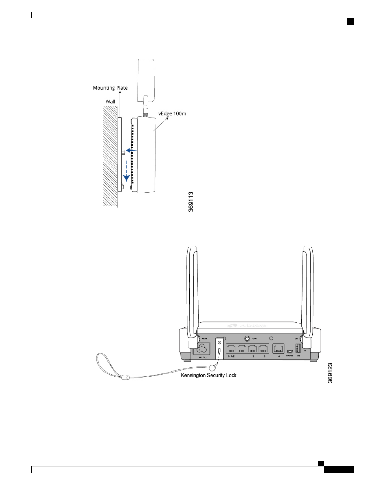
vEdge 100m Router
Connect the vEdge 100m Router
1. Secure the router with a Kensington security lock using the slot in the rear of the chassis.
Figure 11: Securing the Router with a Kensington Security Lock
Connect the vEdge 100m Router
This article describes how to connect the vEdge 100m router to an AC power source and to a management
console.
Hardware Installation Guide for vEdge Routers
69
Page 76

Connect the vEdge 100m Router
Connect AC Power to the Router
To connect the vEdge 100m router to an AC power source, plug one end of the AC power cord into the back
of the router, and plug the other end into an AC power outlet as shown in Figure 1.
Figure 1: Connecting AC Power Supply to a vEdge 100m Router
vEdge 100m Router
Note: It is strongly recommended that you use the power cord supplied with the vEdge 100m router.
Caution: If you are connecting AC power to the router, it is recommended that the building have an external
surge protective device installed.
Connect the Router to LAN and WAN Interfaces
To connect the vEdge 100m router to the LAN, plug the appropriate cable into any port except Port 4 on the
front of the router.
To connect the vEdge 100m router to a WAN, plug the appropriate cable into Port 4 on the front of the router.
Figure 2: Connecting a vEdge 100m Router to LAN and WAN Interfaces
Hardware Installation Guide for vEdge Routers
70
Page 77

vEdge 100m Router
Connect the vEdge 100m Router
Connect the Router to a Management Console
To connect the vEdge 100m router to a management console:
1. Connect one end of the USB Type-A to Mini-B connector cable into the console port, labeled CONSOLE,
on the vEdge router.
2. Connect the other end of the console cable into a management console.
Figure 3: Connecting a vEdge 100m Router to a Management Console
To use the USB console from a Windows device:
1. Go to the Device Manager to determine which COM port is being used for the USB serial port.
Hardware Installation Guide for vEdge Routers
71
Page 78

vEdge 100m Router Default Configuration
2. In the PuTTY SSH/Telnet client, in Connection Type, select Serial. Then, specify the COM port and a
speed of 115200.
vEdge 100m Router
You can download the Windows driver here .
To use the USB console from a Macintosh device:
1. Install the USB serial drivers attached here .
2. Launch the Terminal utility.
3. From a terminal shell, access the console port with this command:
$ screen /dev/tty.usbserial* 115200,cs8
vEdge 100m Router Default Configuration
Default Configuration for Software Releases 16.3 and Later
For Releases 16.3 and later, the default configuration file looks like this:
vEdge100m# show running-config
system
Hardware Installation Guide for vEdge Routers
72
Page 79

vEdge 100m Router
vEdge 100m Router Default Configuration
host-name vedge
vbond ztp.viptela.com
aaa
auth-order local radius tacacs
usergroup basic
task system read write
task interface read write
!
usergroup netadmin
!
usergroup operator
task system read
task interface read
task policy read
task routing read
task security read
!
user admin
password
$6$qKmsMYJ084t8bH5e$vz1mCDB76u74UPJ29cFo7vK5JjNBTutvlT9WhH/EHgUCHwMwoWU9XzfQ4eqUtgwEMdFzWcskcAtb97GxLArXX1
!
!
logging
disk
enable
!
!
!
omp
no shutdown
graceful-restart
advertise connected
advertise static
!
security
ipsec
authentication-type ah-sha1-hmac sha1-hmac
!
!
vpn 0
interface cellular0
ip dhcp-client
tunnel-interface
encapsulation ipsec
color lte
no allow-service bgp
allow-service dhcp
allow-service dns
allow-service icmp
no allow-service sshd
no allow-service netconf
no allow-service ntp
no allow-service ospf
no allow-service stun
!
mtu 1428
profile 0
technology auto (in Releases 16.3.2 and later)
no shutdown
!
interface ge0/4
ip dhcp-client
ipv6 dhcp-client
Hardware Installation Guide for vEdge Routers
73
Page 80

vEdge 100m Router Default Configuration
tunnel-interface
encapsulation ipsec
no allow-service bgp
allow-service dhcp
allow-service dns
allow-service icmp
no allow-service sshd
no allow-service netconf
no allow-service ntp
no allow-service ospf
no allow-service stun
!
no shutdown
!
!
vpn 512
interface ge0/0
ip address 192.168.1.1/24
no shutdown
!
!
Default Configuration for Software Releases 16.2 and Earlier
vEdge 100m Router
For Release 16.2, the default configuration file looks like this:
vEdge100m# show running-config
system
host-name vedge
vbond ztp.viptela.com
aaa
auth-order local radius tacacs
usergroup basic
task system read write
task interface read write
!
usergroup netadmin
!
usergroup operator
task system read
task interface read
task policy read
task routing read
task security read
!
user admin
password
$6$fTBoB4hFbObL96Rh$<wbr/>Tx3voGhKPNeTSjRsQ4AVd3dvS3R.<wbr/>A0DsOcBaNjZgXJiiUU6OldFVpqKKBP<wbr/>1CafW56nMDIi2PNEvVeBSKMf1RL0
!
!
logging
disk
enable
!
!
!
omp
no shutdown
graceful-restart
advertise connected
advertise static
!
security
Hardware Installation Guide for vEdge Routers
74
Page 81

vEdge 100m Router
vEdge 100m Router Default Configuration
ipsec
authentication-type ah-sha1-hmac sha1-hmac
!
!
vpn 0
interface ge0/4
ip dhcp-client
tunnel-interface
encapsulation ipsec
no allow-service bgp
allow-service dhcp
allow-service dns
allow-service icmp
no allow-service sshd
no allow-service netconf
no allow-service ntp
no allow-service ospf
no allow-service stun
!
no shutdown
!
!
vpn 512
interface ge0/0
ip address 192.168.1.1/24
no shutdown
!
!
For Releases 16.2.10 and later, after you install the software and issue the request software reset command, the
default configuration file looks like this:
vEdge100m# show running-config
system
host-name vedge
vbond ztp.viptela.com
aaa
auth-order local radius tacacs
usergroup basic
task system read write
task interface read write
!
usergroup netadmin
!
usergroup operator
task system read
task interface read
task policy read
task routing read
task security read
!
user admin
password
$6$qKmsMYJ084t8bH5e$vz1mCDB76u74UPJ29cFo7vK5JjNBTutvlT9WhH/EHgUCHwMwoWU9XzfQ4eqUtgwEMdFzWcskcAtb97GxLArXX1
!
!
logging
disk
enable
!
!
!
omp
no shutdown
Hardware Installation Guide for vEdge Routers
75
Page 82

vEdge 100m Router Default Configuration
graceful-restart
advertise connected
advertise static
!
security
ipsec
authentication-type ah-sha1-hmac sha1-hmac
!
!
vpn 0
interface cellular0
ip dhcp-client
tunnel-interface
encapsulation ipsec
color lte
no allow-service bgp
allow-service dhcp
allow-service dns
allow-service icmp
no allow-service sshd
no allow-service netconf
no allow-service ntp
no allow-service ospf
no allow-service stun
!
mtu 1428
profile 0
technology auto
no shutdown
!
interface ge0/4
ip dhcp-client
ipv6 dhcp-client
tunnel-interface
encapsulation ipsec
no allow-service bgp
allow-service dhcp
allow-service dns
allow-service icmp
no allow-service sshd
no allow-service netconf
no allow-service ntp
no allow-service ospf
no allow-service stun
!
no shutdown
!
!
vpn 512
interface ge0/0
ip address 192.168.1.1/24
no shutdown
!
!
vEdge 100m Router
Hardware Installation Guide for vEdge Routers
76
Page 83

vEdge 100m Router
Maintenance and Troubleshooting
Maintenance and Troubleshooting
You can monitor and troubleshoot the vEdge 100m router using the various LEDs and system alarms on the
router.
Alarm Severity Levels
The system alarms on the vEdge 100m router have two severity levels:
• Major (red)—Indicates a critical situation on the router resulting from one of two conditions:
• One or more hardware components on the router has failed.
• One or more hardware components on the router has exceeded the temperature threshold.
Maintenance and Troubleshooting
A major alarm condition requires immediate attention. If a temperature related major alarm persists for more
than five minutes, the router will shut down.
• Minor (yellow)—Indicates a warning on the router that, if left unattended, might result in an interruption
in router operation or degradation in router performance. A yellow alarm condition requires further
monitoring and/or maintenance.
Hardware Alarms
Hardware alarms on the vEdge 100m router are predefined and are triggered by a physical condition on the
router such as a power supply failure, excessive component temperature, or fan failure. The vEdge 100m
router triggers the following types of hardware alarms:
• Main board temperature alarm—The main board of the router has one temperature sensing point (board
sensor 0). If the temperature of the sensor location crosses the predefined threshold level, the system
triggers an alarm.
• CPU temperature alarm—If the temperature of the system CPU crosses the predefined threshold level,
the system triggers an alarm.
• Fan alarm—The router has a fixed built-in fan for system cooling which runs at a variable speed. The
Viptela software maintains the fan at an optimal fan speed, raising the speed as the ambient temperature
increases and decreasing the speed as the temperature decreases, to keep the router operating at the lowest
possible temperature in the green temperature threshold. If the fan stops running, the system triggers an
alarm. Also if the fan starts to run below a predefined RPM threshold, the system triggers an alarm.
Table 1 lists the yellow and red alarm threshold for the temperature sensing points in the system—one board
sensor on the board and one CPU junction temperature sensor. The lower threshold value (Bad Fan) applies
if a fan failure condition is also detected; otherwise, the higher threshold value (normal) applies.
Hardware Installation Guide for vEdge Routers
77
Page 84

Restore a vEdge Router
vEdge 100m Router
Table 22:
Item
temperature
Checking Alarms and Notifications
To view the current chassis environment condition , enter the show hardware environment command at
the system prompt. The system displays the power supply status, temperature sensor readings, fan speed, and
related alarm status if any exists.
To view the severity of active alarms, enter the show hardware alarms command at the system prompt. The
system displays the alarm severity and a brief description of the cause of each active alarm.
To view temperature thresholds at which green, yellow, and red alarms are generated, enter the show hardware
temperature-thresholds command at the system prompt. The system displays the alarm temperature threshold
information for a specific board or all boards in the router and for the router's CPU.
To view all other events on a Viptela device, enter the show notification stream command. The system
displays notifications about events that have occurred on the Viptela device.
Yellow
Alarm (ºC)
Red
Alarm (ºC)
Bad FanNormalBad FanNormal
85907075Board sensor 0
90957580CPU junction
LEDs
The chassis LEDs located on the front panel of the vEdge 100m router indicate the status of the router.
If one or more major alarms are active in the router, the Status LED is lit red. If one or more minor alarms
are active in the router, the Status LED is lit solid yellow. See Front and Rear Panel Components for details
of the LEDs and the status they indicate.
Restore a vEdge Router
This article explains how to revert the configuration for a vEdge router to the factory-default values. It also
explains how to do a soft and hard reset of the router.
Reverting to the vEdge Router Factory-Default Configuration
After you set up and start the virtual machines (VMs) for the vEdge Cloud routers and set up and start the
hardware vEdge routers in your overlay network, they come up with a factory-default configuration . When
you make and commit changes to the default configuration, a new configuration file is created. This new
configuration file then becomes the active configuration.
If desired, you can revert to the default factory configuration:
vEdge# request software reset
Hardware Installation Guide for vEdge Routers
78
Page 85

vEdge 100m Router
Return Hardware
Reset the Router
You can reset the vEdge router by doing either a hard press or a soft press. To perform either type of press,
locate the Reset button on the front panel of the router. The Reset button is recessed to avoid accidentally
pressing it while the router is operational. To press the Reset button, use a sharp narrow tool.
Perform a Long Press Reset
A long press reset of the vEdge router erases passwords, keys, and most other configuration parameters,
restoring the router to its factory-default configuration.
To perform a long press reset, press the Reset button for more than 10 seconds. After you release the Reset
button, the router will reboot and resume normal operation.
Perform a Short Press Reset
A short press reset of the Edge router is equivalent to a graceful software reboot and is the same as entering
the reboot command at the CLI prompt.
To perform a short press reset, press the Reset button for two seconds. The short press reset takes effect almost
instantaneously and reboots the router.
Return Hardware
This article describes how to return a vEdge router or a hardware component to Viptela for repair or replacement.
Locate Serial and Model Number
To return a vEdge router or a hardware component to Viptela, you need the serial and model number of the
router or the component being returned.
You can locate the serial and model number of a vEdge router in one of the following ways:
• In vManage NMS, select the Configuration ► Devices screen. The device table lists the serial and model
numbers of the routers in the network.
• Enter the show hardware inventory command at the CLI prompt.
• The serial number (sample shown in Figure 1) is printed on a label on the right side of the router; the
model number is printed on a label on the back of the router.
Figure 1: Sample Serial Number Label for a vEdge Router
Hardware Installation Guide for vEdge Routers
79
Page 86

Return Hardware
vEdge 100m Router
Obtain an RMA Number
If you are returning a vEdge router or a hardware component to Viptela for repair or replacement, contact the
Viptela Customer Support team to open a support case and obtain a Return Materials Authorization (RMA)
number.
Before you open a case and request an RMA number, keep the following information ready:
• Your existing service contract number, if you have one
• Serial number of the router or component
• Model number of the router or component
• Physical location of the router
• Your name, organization name, telephone number, fax number, and shipping address
• Failure or problem description with details
• Type of activity being performed on the router when the problem occurred
• Configuration data displayed by one or more show commands
To obtain an RMA number:
1. Open a support case with Viptela in one of the following ways:
• Log in to www.viptela.com/support
• Send email to support@viptela.com
• Call toll-free 800-525-5033
1. A Viptela Customer Support representative validates your request and issues an RMA number for returning
the router or a hardware component.
Note: Do not return the router or any component to Viptela before first obtaining an RMA number. Viptela
reserves the right to refuse to take any shipment that does not have an RMA number.
Repack the Router
If you need to move or return the vEdge router, repack the router in its original packing. Before you repack
the router follow these steps:
1. Shut down the vEdge router by issuing the poweroff command at the CLI prompt.
2. Disconnect power to the router.
3. Remove the cables and transceivers.
You will need the following tools to repack the router:
• Phillips Number 2 (+) screwdriver
• Cardboard carton and original packing in which you received the router
To repack the router in its original packing:
1. If you do not have a vEdge 1000 router, skip this step. Otherwise:
Hardware Installation Guide for vEdge Routers
80
Page 87

vEdge 100m Router
Return Hardware
If the router is installed in a rack using the rack-mount kit from Viptela, remove the front stopper
1.
screwed along the front side of the rack-mount tray.
2. Then remove the rack-mount tray from the rack by having one person support the weight of the
rack-mount tray while a second person unscrews the rack-mount screws.
3. Place the rack-mount tray on a firm, flat surface.
4. Slide out the vEdge 1000 router from the rack-mount tray.
2. Place the router chassis in the plastic packing bag.
3. Place the side packing foam on both sides of the router chassis.
4. Secure the chassis in the cardboard carton.
5. Secure the top of the chassis by placing the top packing foam over the top of the chassis.
6. Close the cardboard shipping box and seal it with packing tape.
7. Write the RMA number on top of the box for purposes of tracking.
If you are returning any field-replaceable units with the router, repack them as described in Repack Router
Components below.
Repack Router Components
If you need to return any router components, follow these steps:
1. Ensure that you have the antistatic bag for each component and an ESD grounding strap.
2. Place each component in its antistatic bag.
3. Pack each component in its original packing material. If you do not have the original packing material,
ensure that the component is packed adequately with packing material to prevent any damage in transit.
4. Place the component in the original cardboard box or another cardboard box if the original is not available.
5. Secure the box with tape.
6. Write the RMA number on top of the box for purposes of tracking.
Hardware Installation Guide for vEdge Routers
81
Page 88

Return Hardware
vEdge 100m Router
Hardware Installation Guide for vEdge Routers
82
Page 89

CHAPTER 4
vEdge 100wm Router
The vEdge 100wm router delivers highly secure site-to-site data connectivity to small business and home
offices (SOHO). The vEdge 100wm router is a fixed-port-configuration router with the following features:
• Built-in LTE modem with mini-SIM (or 2FF) card
• Two multiband swivel-mount dipole antennas
• Supports a 4G/3G/2G–capable modem to connect to cellular networks
• Wi-Fi access point capability
• Wi-Fi radio configurable for 2.4 GHz or 5.0 GHz
• Five built-in 10/100/1000–Mbps Ethernet ports
• Power over Ethernet (PoE) source support on one Ethernet port
• Encryption and QoS support
• 100 Mbps forwarding throughput (inclusive of encryption)
• Secure identification chip for anticounterfeit and secure authentication
• Integrated power supply
• Kensington security lock slot to physically lock down the router
• GPS input for geographical location
• Desktop mount or wall mount
Chassis Views
Figure 1 and Figure 2 show the front and back panels of the vEdge 100wm router, indicating the locations of
the power interfaces, status indicators, and chassis identification labels.
Figure 1: Front Panel of the vEdge 100wm Router
Hardware Installation Guide for vEdge Routers
83
Page 90

Declaration of Conformity
vEdge 100wm Router
Figure 2: Back Panel of the vEdge 100wm Router
• Declaration of Conformity, on page 84
• Components and Specifications, on page 85
• Planning and Installation, on page 93
• Maintenance and Troubleshooting, on page 105
Declaration of Conformity
The Viptela products are controlled under the Commerce Control List (CCL) of the U.S. Export Administration
Regulations (EAR) as networking equipment within the following U.S. Export Control Classification Numbers
(ECCN): 5A002, 5D002, and 5E002.
The vEdge hardware and software products and the Viptela encryption technology can be delivered to most
end users and destinations worldwide without a licensing requirement. The Viptela solution and products
have undergone a one-time review by the Government of the United States of America and qualify for License
Exception ENC. As such, they are eligible for export according to Section 740.17 of the EAR.
The Viptela solutions and products can be delivered to most end users worldwide, except to entities or end
users in the following countries: Cuba, Iran, North Korea, Sudan, and Syria.
Controlled Technologies
Viptela manages technology subject to the U.S. Export Administration Regulations (EAR). These controlled
technologies may include items under U.S. ECCN 5E002 encryption technology. The Viptela encryption
technology is for the development, production, and use of Viptela products that implement or use encryption.
Hardware Installation Guide for vEdge Routers
84
Page 91

vEdge 100wm Router
The Viptela software distribution policy allows only authenticated users to download the Viptela encryption
software. Recipients of controlled technology are obliged to maintain adequate controls to prevent nationals
from outside the U.S. and Canada from accessing Viptela information, subject to ECCN5E002, without first
obtaining authorization from the U.S. government.
For additional information on controlled technologies, please contact Viptela support at support@viptela.com
.
Components and Specifications
This article provides specifications for the vEdge 100wm chassis, wireless platforms,
and multiband swivel-mount dipole antennas.
Chassis Specifications
Table 1 lists the specifications for the vEdge 100wm router chassis.
Table 23:
Components and Specifications
Services and Slot Density
RJ45 Ports 10/100/1000 Mbps
(IPSec)
115.2 Kbps)
Power Specifications
AC input voltage
SpecificationItem
5 ports, one of which has 802.3af PoE source
capability
YesEmbedded hardware-based cryptographic acceleration
2 GBMemory DDR3 ECC DRAM
4 GBNAND storage (internal)
1USB host port
1Mini USB connector console port (default baud rate
AC input (C6 inlet connector)Power supply
90-264 Vrms
47-63 HzAC input line frequency
interface ge0/0
interface ge0/0
Physical Specifications (excluding the
multiband antennas)
20 WattsTypical power consumption with PoE disabled on
35 Watts maximumTypical power consumption with PoE enabled on
Hardware Installation Guide for vEdge Routers
85
Page 92

Components and Specifications
vEdge 100wm Router
SpecificationItem
Chassis height
Packaging Specifications
Package height
Operating Condition
Temperature
1.8 in. (4.5 cm)
9.25 in. (23.5 cm)Chassis width
5.75 in. (14.6 cm)Chassis depth
1.45 lbs (0.67 kg)Chassis weight
Provided with the unitWall-mount plate accessory
5.375 in. (13.6 cm)
11.94 in. (30.3 cm)Package width
9.19 in. (23.3 cm)Package depth
0 to 40°C (32 to 104°F) at sea level (temperature
derating of 1.5°C per 1000 feet of altitude, up to a
maximum of 10,000 ft, or 3000 m)
Maximum 3000 m (10,000 ft)Altitude
10 to 85% RHHumidity
Transportation/Storage Condition
Temperature
–40 to 70°C (–40 to 158°F)
5 to 95% RHHumidity
4570 m (15,000 ft)Altitude
Reliability
MTBF
104,000 hours
Regulatory Compliance
Safety
AS/NZS 60950-1 CAN/CSA 60950-1
CB-IEC60950-1 CE Marking EN 60950-1
UL60950-1
EMC
AS/NZS CISPR22 Class B EN 300 386 EN 55022
Class B FCC Class B ICES Class B VCCI Class B
ROHS 6/6Environmental
Wireless Platform Specifications
Table 2 lists the specifications for the vEdge 100wm wireless platforms.
Hardware Installation Guide for vEdge Routers
86
Page 93

vEdge 100wm Router
Components and Specifications
Table 24:
SpecificationPlatform
vEdge 100wm-AT
SKU
4G LTE Bands
vEdge 100wm-GB
SKU
4G LTE Bands
vEdge 100wm-NA
SKU
100wm-AT
AT&TCarrier
Sierra Wireless MC7354Modem
Band 2 (1900 MHz), Band 4 (AWS 1700/2100 MHz), Band 5 (850 MHz), Band 17
(700 MHz)
United StatesRegion
100wm-GB
GCFCertification
Sierra Wireless MC7304Modem
Band 1 (2100 MHz), Band 3 (1800 MHz), Band 7 (2600 MHz), Band 8 (900MHz),
Band 20 (800 MHz)
Australia, Europe, Middle East, Latin America, Asia PacificRegions
100wm-NA
4G LTE Bands
vEdge 100wm-NT
SKU
vEdge 100wm-SP
PTCRBCertification
Sierra Wireless MC7354Modem
Band 2 (1900 MHz), Band 4 (AWS 1700/2100 MHz), Band 5 (850 MHz), Band 13
(700 MHz), Band 17 (700 MHz), Band 25 (1900 MHz)
North AmericaRegion
100wm-NT
NTT DocomoCarrier
Sierra Wireless MC7330Modem
Band 1 (2100 MHz), Band 19 (850 MHz), Band 21 (1500 MHz)4G LTE Bands
JapanRegion
Hardware Installation Guide for vEdge Routers
87
Page 94

Components and Specifications
vEdge 100wm-VZ
vEdge 100wm Router
SpecificationPlatform
100wm-SPSKU
SprintCarrier
Sierra Wireless MC7354Modem
Band 25 (1900 MHz)4G LTE Bands
United StatesRegion
SKU
100wm-VZ
VerizonCarrier
Sierra Wireless MC7354Modem
Band 4 (AWS 1700/2100 MHz), Band 13 (700 MHz)4G LTE Bands
United StatesRegion
Multiband Cellular Antenna Specifications
The vEdge 100wm router ships with two multiband swivel-mount dipole antennas. The articulating joint of
the antenna provides 0 to 90 degrees pivot and 180-degree swivel movement, allowing vertical and horizontal
orientation of the antenna.
Table 3 lists the electrical, mechanical, and frequency specifications for the antennas.
Table 3: vEdge 100wm Multiband Cellular Antenna Specifications
Table 25:
SpecificationItem
MIMO, dipole swivelAntenna type
10 WattsInput power
SMA maleConnector
50 OhmsNominal
impedance
OmnidirectionalRadiation pattern
698MHz to 960MHz and 1710MHz to 2700MhzFrequency range
F (–40°C to 85°C)Temperature range
Hardware Installation Guide for vEdge Routers
88
Page 95

vEdge 100wm Router
Front and Rear Panel Components
SpecificationItem
Antenna
dimensions
Length: 6.37 in. (16.19 cm)
Width: 0.9 in. (2.38 cm)
Depth: 0.63 in. (1.59 cm)
Noncondensing, 65°C, 95% RHHumidity
Wi-Fi Specifications
The vEdge 100wm router provides the following Wi-FI capabilities:
• Embedded Wi-Fi radio for access point functionality
• Wi-Fi radio configurable for 2.4-GHz or 5.0-GHz operation
• Supports IEEE 802.11a, 802.11b, 802.11g, 802.11 n, and 802.11ac protocols
• Supports channel bandwidth of 20 MHz, 40 MHz, and 80 MHz
• Supports IEEE 802.11h DFS channels
• 3x3 MIMO with three spatial streams
• Supports up to four different SSIDs
• Supports up to 50 concurrent clients
• Supports wireless security and authentication:
• Personal and enterprise WPA/WPA2
• AES/CCMP encryption
• TKIP encryption
• Internal embedded antennas
Front and Rear Panel Components
This article describes the components on the front and rear panels of the vEdge 100wm router. For the exact
location of these components on the router, see At a Glance .
Front Panel LEDs
The vEdge 100wm router has five chassis status LEDs located on the front panel. Table 1 describes the LEDs,
their color and states, and the status they indicate.
Hardware Installation Guide for vEdge Routers
89
Page 96

Front and Rear Panel Components
Table 26:
vEdge 100wm Router
StatusColorLED
(LED 0–4)
Green/RedPower
• Off: System is not on
• Green: System power is healthy and operational
• Red: Power supply fault
Green/Yellow/RedSystem
• Off: System is not on
• Solid Green: System is fully functional
• Blinking Green: System is booting up
• Solid Yellow: No Internet connectivity or the system has detected
a minor alarm
• Red: System has detected a major system level fault or alarm
Green/YellowEthernet Port
• Off: No link
• Solid Green: 1000 Mbps link detected
• Blinking Green: 1000 Mbps link detected and link activity
• Solid yellow: 10/100 Mbps link detected
• Blinking Yellow: 10/100 Mbps link detected and link activity
GreenWiFi Status
• Off: WiFi interface disabled/off
• Solid Yellow: WiFi enabled
• Blinking Green: WiFi client connected and link activity
Green/Yellow/RedWWAN Signal
Strength
• Off: LTE interface disabled/off
• Solid Green: LTE enabled, excellent signal strength, dormant
mode
• Blinking Green: LTE enabled, excellent signal strength, active
mode
• Solid yellow: LTE enabled, good signal strength, dormant mode
• Blinking Yellow: LTE enabled, good signal strength, active mode
• Solid Orange: LTE enabled, poor signal strength, dormant mode
• Blinking Orange: LTE enabled, poor signal strength, active mode
• Solid Red: LTE enabled but faulty such as no connectivity with
BTS, errors, or no signal
Figure 1 shows the location of the chassis status LEDs on the front panel of the vEdge 100wm router.
Hardware Installation Guide for vEdge Routers
90
Page 97

vEdge 100wm Router
Front and Rear Panel Components
Figure 1: Chassis Status LEDs in a vEdge 100wm Router (UPDATE)
Rear Panel
The rear panel of the vEdge 100wm router has two cellular antenna terminals, a GPS antenna input, a
Kensington security lock slot, and a Reset button. See Chassis Views for the location of these components.
Cellular Antenna Terminals
The rear panel of the vEdge 100wm router has two SMA antenna terminals for attaching the two multiband
swivel-mount dipole antennas that ship with the router. For antenna specifications, see
Multiband Cellular Antenna Specifications .
GPS Input
The GPS antenna input on the rear panel of the vEdge 100wm router allows you to connect an external GPS
antenna that has an SMA connector. If you connect a GPS antenna to the router, it can automatically identify
the router's geographical location.
Kensington Security Lock Slot
The rear panel of the vEdge 100wm router has a small metal-enforced hole for attaching a Kensington lock
to secure the router.
Reset Button
The Reset button on the rear panel of the vEdge 100wm router is recessed, to avoid accidentally pressing it
while the router is operational. To press the Reset button, use a sharp narrow tool. Table 2 describes the effects
of pressing the Reset button.
Table 27:
BehaviorPress
Duration
Press for 2 seconds to reset and reboot the router.Short press
Press for 10 seconds to reset the router and reboot it with factory default configuration.Long press
Hardware Installation Guide for vEdge Routers
91
Page 98

Ports and Connectors
Ports and Connectors
The vEdge 100wm router supports three types of ports:
• RJ-45 Ethernet ports
• USB port
• USB serial console port.
RJ-45 Ethernet Ports
The vEdge 100wm router has five built-in RJ-45 Ethernet ports. These ports support 10/100/1000 Mbps and
are numbered 0 through 4. Port 0 supports PoE capability.
Figure 1 provides the pinout information for the RJ-45 ports. The RJ-45 ports comply with the 801 standards.
Figure 1: RJ-45 Ports Pinout Information
vEdge 100wm Router
USB Port
The vEdge 100wm router has one USB host port with a type A connector. The USB port supports USB 3.0
speeds.
Console Port
The vEdge 100wm console port is a serial port and is accessible via a USB Mini-B connector. See Figure 2.
Figure 2: USB Mini-B Connector
A USB Type-A to Mini-B connector cable ships with the vEdge 100wm router as standard accessory for
console port connection.
Hardware Installation Guide for vEdge Routers
92
Page 99

vEdge 100wm Router
Power Supply and Cooling System
The vEdge 100wm router has an built-in AC-to-DC power supply unit. This article describes the AC power
supply in the router and the cooling system and airflow through the router chassis.
AC Power Supply in vEdge 100wm Router
The vEdge 100wm router has an integrated AC power supply that exposes a C6 male AC inlet connector
externally. The unit can be powered by connecting the supplied power cord to AC mains with the C5 female
connector end of power cord plugged into the unit.
Table 1 describes the AC power supply specifications for the vEdge 100wm router.
Table 28:
Power Supply and Cooling System
SpecificationItem
90-264 VrmsAC input voltage
47-63 HzAC input line frequency
0
Typical power consumption with PoE enabled on ethernet port
0
AC Power Cord Specifications
The vEdge 100wm router ships with a detachable AC power cord. The power cord has a C5 female connector
at one end, and the other end is specific to the country/locality to which the product is shipped.
Cooling System in a vEdge 100wm Router
The cooling system in a vEdge 100wm router consists of internal heat sinks and an internal fan with adjustable
speed. The fan speed is algorithmically controlled, based on readings obtained from internal temperature
sensors. The internal temperature is affected by factors such as the external ambient temperature and the traffic
workload.
If the ambient temperature inside the chassis rises above the acceptable range, the router raises an alarm. If
the temperature inside the chassis rises above the maximum threshold temperature, the router shuts down
automatically.
Planning and Installation
20 WattsTypical power consumption with PoE disabled on ethernet port
35 Watts
maximum
This article provides general safety standards to adhere to when installing or connecting a vEdge 100wm
router or its components.
General Safety Standards
• Install your vEdge router in compliance with the following local, national, and international electrical
codes:
Hardware Installation Guide for vEdge Routers
93
Page 100

Prepare for Router Installation
• Locate the emergency power-off switch in the room in which you are working. In case of an electrical
• Disconnect power before installing or removing the router.
• If an electrical accident occurs, use caution and immediately turn off power to the router.
• Make sure that grounding surfaces are thoroughly cleaned and well-finished before grounding connections
• Do not work alone if hazardous conditions exist.
vEdge 100wm Router
United States—National Fire Protection Association (NFPA 70), United States National Electrical
•
Code.
• Other countries—International Electromechanical Commission (IEC) 60364, Part 1 through Part
7.
• Evaluated to the TN power system.
• Canada—Canadian Electrical Code, Part 1, CSA C22.1.
accident, quickly turn off the power.
are made.
• Always check that power is disconnected from a circuit. Never assume that it is disconnected.
• Carefully inspect your work area for possible hazards, such as moist floors, worn-out power cords,
ungrounded power extension cords, and missing safety grounds.
• Operate the device within marked electrical ratings and product usage instructions.
• To ensure that the router and the FRUs function safely and correctly, use the specified cables and
connectors, and make certain they are in good condition.
Prepare for Router Installation
This article provide guidelines and requirements for preparing your site to install the vEdge 100wm router.
Site Preparation Guidelines
Efficient operation of your vEdge 100wm router requires proper site planning and proper layout of your
equipment rack or wiring closet:
• Ensure that the area around the router is kept free of dust and conductive material.
• Follow appropriate airflow guidelines so that the cooling system functions normally.
• Follow ESD prevention procedures to avoid any damage to the router.
• Install the router in an enclosed, secure area allowing only authorized personnel to access the device.
Environmental Requirements
Install the vEdge 100wm router in a dry, clean, temperature-controlled, and well-ventilated environment:
• Maintain ambient airflow for the router to operate normally. The ambient intake air temperature should
be in the range 0°C to 40°C (32°F to 104°F). If the airflow is blocked or if the intake air is too warm,
the router can become overheated.
Hardware Installation Guide for vEdge Routers
94
 Loading...