

Page 1
REVIEW DRAFT—CISCO CONFIDENTIAL
Introduction
APPENDIX
A
Repackaging the Router
Revised: February 12, 2008, OL-xxxxx-xx
This appendix describes two separate but related router repackaging tasks:
• How to remove the router from the equipment rack and repackage the router
for shipment if it becomes necessary to transport it to another location or
return it to Cisco Systems.
• How to repackage a defective chassis to return it to the factory.
Where appropriate, you are referred to specific procedures in Chapter 3,
“Installing the Router,”and Chapter 5, “Maintaining the Router.”
This appendix contains the following sections:
• Repackaging the Routers, page A-1
• Repackaging the Replaced Router Chassis, page A-24
Repackaging the Routers
This section describes how to remove the entire router system from the equipment
rack and repackage the router should it become necessary to transport it to another
location or return it to Cisco Systems.
OL-xxxxx-xx
Cisco XR 12416 Router Chassis Installation Guide
A-1
Page 2
Repackaging the Routers
REVIEW DRAFT—CISCO CONFIDENTIAL
This section contains the following information and procedures:
• The Router Shipping Package, page A-2
• Tools and Equipment, page A-6
• Safety Recommendations, page A-6
• Removing the Router from the Rack, page A-7
• Installing the Router on the Shipping Pallet, page A-16
• Completing the Repackaging, page A-23
Note You must use the original shipping package supplied by Cisco when repackaging
the router. If you do not have the original system package, contact your
Cisco service representative for assistance.
The Router Shipping Package
Figure A-1 shows the router in an exploded view of the parts making up the
shipping package components.
Because of the weight and height of the router, the router shipping pallet
incorporates a scissor-jack platform. This scissor-jack platform enables a team of
two installers to remove a fully-loaded router from the pallet and insert it into an
equipment rack, or extract a fully loaded router from a rack, without removing any
of the components from the router chassis.
Appendix A Repackaging the Router
A-2
The router should be bagged to protect it against dust and electrostatic discharge
(ESD) and secured to the scissor-jack platform by four anchor clips. The anchor
clips are inserted into slots along the bottom edges of the router chassis side
panels and secured to the scissor-jack platform by four bolts. In turn, the
scissor-jack platform is secured to the shipping pallet by eight hold-down brackets
that are bolted to the top of the shipping pallet.
The shipping pallet consists of a U-shaped wood and foam pallet body and a wood
and foam pallet front bar. The pallet front bar fastens to the open end of the pallet
body to create the fourth bearing surface for the scissor-jack platform and to
complete the base needed to support the walls of the shipping container.
Cisco XR 12416 Router Chassis Installation Guide
OL-xxxxx-xx
Page 3
Appendix A Repackaging the Router
REVIEW DRAFT—CISCO CONFIDENTIAL
When the router and scissor-jack platform are installed on the pallet, the router
and scissor-jack platform are suspended over the well formed by the pallet body
and pallet front bar. When the scissor-jack platform is expanded to lower the
platform base and support the weight of the router, the bolts securing the
hold-down brackets to the top of the pallet can be removed. After the brackets
have been detached from the pallet, the router and scissor-jack platform can be
separated from the pallet by removing the pallet front bar from the pallet body and
pulling the pallet body away from the scissor-jack platform.
The side walls of the shipping container are formed by two U-shaped, interlocking
corrugated panels. The panels overlap to form the narrow ends of the container
and are locked together by twelve plastic locking clips inserted into holes in the
corrugated panels. Two foam inserts fit around the top of the router to act as a
protective cushion and add rigidity to the packaging scheme by serving as a fixed
buffer between the router, the corrugated side walls of the shipping container, and
the corrugated top cap that holds the side walls in place. With the corrugated top
cap installed, the entire shipping package is double-strapped end-to-end and
side-to-side to secure the shipping container and its contents to the pallet.
Repackaging the Routers
OL-xxxxx-xx
Cisco XR 12416 Router Chassis Installation Guide
A-3
Page 4
Repackaging the Routers
29660
REVIEW DRAFT—CISCO CONFIDENTIAL
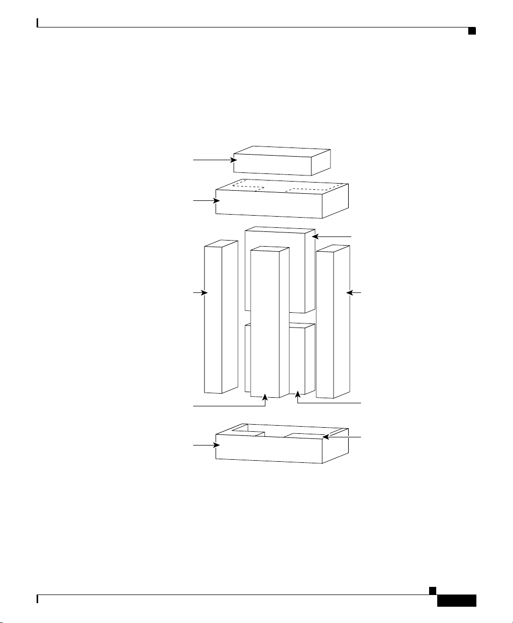
Figure A-1 Router Shipping Package Components
OPEN
Appendix A Repackaging the Router
Top cap
Foam cap
U-shaped panel
A-4
PalletAccessories package
Cisco XR 12416 Router Chassis Installation Guide
OL-xxxxx-xx
Page 5
Appendix A Repackaging the Router
REVIEW DRAFT—CISCO CONFIDENTIAL
The accessories for the router ship in five boxes that are assembled into a package.
(See Figure A-2.) The accessories package is packed against the back panel of the
router on the extended deck of the pallet body.
Figure A-2 Router Accessories Package
Corrugated
spacer
Top cap
Repackaging the Routers
Accessory box
Cable
trough
Center-mount
rack-mounting
brackets
Bottom cap
Cable
trough
Rack-mounting
platform
Foam
29661
OL-xxxxx-xx
Cisco XR 12416 Router Chassis Installation Guide
A-5
Page 6

Repackaging the Routers
REVIEW DRAFT—CISCO CONFIDENTIAL
Tools and Equipment
You need the following items to remove the router from the equipment rack and
repackage it for shipping:
• ESD-preventive wrist strap
• Flat-blade screwdrivers
• Number 1 and number 2 Phillips screwdrivers
• 3/8-inch (10-mm) nutdriver (for systems equipped with the DC-input power
shelf)
• 9/16-inch (14-mm wrench) wrench
• 3/4-inch (19-mm) socket and ratchet wrench
• Safety hand truck with retractable safety leg wheels and security strap, such
as the Stevens Appliance Truck Company “Escort,” Model STEV SRT-M-66
(distributed by McMaster-Carr as Model 2654T6), or an equivalent safety
hand truck.
• Antistatic sacks or other ESD-preventive storage environment
• The original router shipping package supplied by Cisco. If you do not have
the original router shipping package, contact your Cisco service
representative for assistance.
Appendix A Repackaging the Router
Safety Recommendations
Before you begin the procedures in this appendix, review the following safety
information:
• The safety recommendations listed in the“Safety Recommendations” section
on page 2-2 in Chapter 2, “Preparing for Installation.”
• The safety warnings listed in the publication Regulatory Compliance and
Safety Information for the Cisco 12000 Series Internet Router that
accompanied your router
Cisco XR 12416 Router Chassis Installation Guide
A-6
OL-xxxxx-xx
Page 7
Appendix A Repackaging the Router
REVIEW DRAFT—CISCO CONFIDENTIAL
Removing the Router from the Rack
This section describes how to remove the router from the equipment rack.
A fully-equipped router can weigh as much as 415 lb (188 kg). Because of the
weight and height of the router, Cisco provides a rack-mounting system for the
router that enables a team of two installers to extract a fully-loaded router from a
rack without removing any of the components from the router chassis. For
information on the router rack-mounting system, refer to “A fully equipped router
with an optional two-level AC-input power shelf can weigh as much as
440 pounds (200 kg). The router ships on a scissor-jack platform that enables two
people to install a fully loaded router into a rack without removing any of the
components from the chassis.” section on page 3-2.
Note As an option, you can elect to remove some of the components from the chassis
to reduce the top-end weight of the chassis and lower the center of gravity, making
the chassis more stable as you move it. The procedures for removing components
are described in the “Unpacking and Positioning the Router” section on page 3-3.
Repackaging the Routers
Procedures in the following sections describe the steps for removing the chassis
from the equipment rack:
• Powering Down the Router, page A-7
• Removing the Front Covers, page A-8
• Disconnecting RP Cables, page A-8
• Disconnecting Alarm Card Cables, page A-8
• Disconnecting Power Cables from the Power Shelf, page A-8
• Removing Components from the Chassis to Reduce Weight, page A-9
• Detaching the Supplemental Bonding and Grounding Connection, page A-10
• Removing the Router from the Equipment Rack, page A-11
Powering Down the Router
Power down the router as instructed in the “Powering Down the Router” section
on page 5-2.
OL-xxxxx-xx
Cisco XR 12416 Router Chassis Installation Guide
A-7
Page 8
Repackaging the Routers
REVIEW DRAFT—CISCO CONFIDENTIAL
Removing the Front Covers
Remove all of the front covers from the chassis as instructed in the “Removing the
Chassis Front Covers” section on page 3-7. You will install them on the chassis
after it has been secured on the shipping pallet?
Disconnecting RP Cables
You must disconnect any cables that are connected to the RP console port,
auxiliary port, or either of the Ethernet ports, RJ-45 or MII. Identify each of the
RP cable connections and write them down on a piece of paper before you
disconnect the cables. After disconnecting the cables, remove them from the
chassis and place them safely aside.
Refer to the following descriptions in Chapter 2, “Preparing for Installation.” for
information on RP cables:
• GRP Console and Auxiliary Port Connection Guidelines, page 2-24
• PRP Console and Auxiliary Port Connection Guidelines, page 2-27
• GRP Ethernet Connection Equipment, page 2-29
• PRP Ethernet Connection Equipment, page 2-36
Appendix A Repackaging the Router
Disconnecting Alarm Card Cables
You must disconnect any cable that is connected to the external alarm port on
either or both of the alarm cards. Identify the alarm cable connections and write
them down on a piece of paper before you disconnect the cables. After
disconnecting the cables, remove them from the chassis and place them safely
aside.
For information on alarm card cables, refer to the “Alarm Card Connection
Guidelines” section on page 2-33.
Disconnecting Power Cables from the Power Shelf
If your router is equipped with either the standard or optional AC-input power
shelf, disconnect the AC-input power cords from their receptacles on the back
panel of the power shelf as instructed in the “Removing and Installing the
Standard One-Level AC-Input Power Shelf” section on page 5-32.
Cisco XR 12416 Router Chassis Installation Guide
A-8
OL-xxxxx-xx
Page 9

Appendix A Repackaging the Router
REVIEW DRAFT—CISCO CONFIDENTIAL
If your router is equipped with the DC-input power shelf, disconnect the eight
source DC positive and negative power cables and the single ground cable from
the terminal studs on the back panel of the power shelf as instructed in the
“Removing and Installing a DC-Input Power Shelf” section on page 5-54.
Removing Components from the Chassis to Reduce Weight
A fully-equipped router can weigh as much as 415 lb (188 kg). To reduce the
top-end weight of the chassis and lower the center of gravity, which might make
the chassis more stable as you move it, you may choose to remove some of the
components from the chassis.
Procedures in the following sections describe the steps for removing some of the
router components:
• Removing Power Modules, page A-9
• Removing the Blower Modules, page A-10
• Removing the Cards from the Chassis Card Cages, page A-10
Removing Power Modules
Repackaging the Routers
OL-xxxxx-xx
Each AC-input power supply weighs 12.7 lb (5.7 kg). By electing to remove the
three power supplies from the standard AC-input power shelf, you reduce the
top-end weight of the chassis by approximately 38.1 lb (17.1 kg). By electing to
remove the four power supplies from the optional AC-input power shelf, you
reduce the top-end weight of the chassis by approximately 50.8 lb (22.8kg)
Remove the AC-input power supplies as described in the “Installing AC-Input
Power Supplies” section on page 3-75.
Each DC-input power entry module weighs 6.4 lb (2.9 kg). By electing to remove
the four power entry modules from the power shelf, you reduce the top-end weight
of the chassis by approximately 25.6 lb (11.6 kg). Remove the DC-input power
entry modules as described in the“Removing DC-Input PEMs” section on
page 3-12.
Cisco XR 12416 Router Chassis Installation Guide
A-9
Page 10

Repackaging the Routers
REVIEW DRAFT—CISCO CONFIDENTIAL
Removing the Blower Modules
The blower module weighs 20.5 lb (9.3 kg). By removing the upper blower
module from the chassis, you reduce the top-end weight of the chassis by the
weight of the blower module. Unless you plan to strip all components to reduce
the overall weight of the chassis so you can shift the chassis by lifting it manually,
there is no advantage in removing the lower blower module. Remove the blower
modules as described in the “Removing the Blower Modules” section on
page 3-14.
Removing the Cards from the Chassis Card Cages
Unless you plan to strip all components to reduce the overall weight of the chassis
so you can shift the chassis by lifting it manually, there is no advantage in
removing the cards from the card cages. Reducing the overall weight of the
chassis is offset by the requirement to store the cards in an ESD-preventive and
dust proof (for fiber-optic cards) environment.
If you elect to remove the cards from the chassis card cages, remove the cards as
described in Chapter 3, “Installing the Router.”
• Removing the Cards from the Upper Card Cage, page 3-18,
• Removing the Cards from the Lower Card Cage, page 3-20,
• Removing the Cards from the Switch Fabric Card Cage, page 3-22
Appendix A Repackaging the Router
Detaching the Supplemental Bonding and Grounding Connection
If your router has one or more bonding and grounding cables attached to any of
the bonding and grounding receptacles on the chassis, you must detach these cable
lugs from the chassis before you remove the chassis from the equipment rack.
Detach the bonding and grounding cable lugs from the chassis as instructed in the
“Detaching the Supplemental Bonding and Grounding Connection” section on
page 5-104.
Cisco XR 12416 Router Chassis Installation Guide
A-10
OL-xxxxx-xx
Page 11

Appendix A Repackaging the Router
REVIEW DRAFT—CISCO CONFIDENTIAL
Removing the Router from the Equipment Rack
This section describes how to remove a fully-loaded router from the equipment
rack using the scissor-jack platform. If you elected to empty the chassis before
attempting to remove it from the equipment rack, remove the chassis as described
in the “Removing and Installing a Chassis” section on page 5-53.
To remove a fully-loaded router from the equipment rack using the scissor-jack
platform, follow these steps:
Step 1 Working from the top of the chassis down, remove the screws that secure the
chassis to the mounting flanges on the rack (five screws on each side of the
chassis).
Step 2 Position the scissor-jack platform in front of the rack-mounting platform installed
in the bottom of the rack, with the screw on the scissor-jack platform facing away
from the front of the router and the back of the scissor-jack platform butted
against the front of the rack-mounting platform.
Step 3 Use the 3/4-in (19-mm) socket and ratchet wrench to turn the scissor-jack screw
counterclockwise and expand the scissor-jack platform so that the top of the
platform is level with the top of the rack-mounting table under the chassis.
(See Figure A-3.)
Repackaging the Routers
OL-xxxxx-xx
Cisco XR 12416 Router Chassis Installation Guide
A-11
Page 12

Repackaging the Routers
REVIEW DRAFT—CISCO CONFIDENTIAL
Figure A-3 Preparing the Scissor-Jack Platform
E
L
O
S
N
O
C
X
T
E
U
S
A
E
R
1
0
-
-
T
T
O
O
L
L
S
S
T
C
E
J
E
L
L
E
C
R
E
X
I
R
R
R
A
E
C
V
I
T
C
A
PKT
RX
IER
CARR
0
ACTIVE
Appendix A Repackaging the Router
RX
IER
R
6
R
CA
TIVE
TX
C
A
T
L
/
O
RX
5
TX
RX
4
TX
RX
3
TX
RX
2
TX
RX
1
TX
RX
0
TX
CDHNT CD
LOOP RA LA
DOWN
C
A
RX
5
2
TX
RX
T
K
R
P
R
O
4
RX
RIE
N
I
R
M
R
CA
O
TX
J
TIVE
A
M
AC
L
A
C
I
T
I
R
C
RX
3
1
TX
RX
KT
2
R
P
X
IE
R
R
TX
AR
C
TIVE
AC
RX
1
TX
0
RX
0
TX
CDHNT CD
LOOP RA LA
DOWN
29189
A-12
Warning
Do not attempt to lift the chassis with the handles on the back and sides of the
chassis. These handles are not designed to support the weight of the chassis,
and should be used only to steady and guide the chassis while it is being
inserted into or removed from an equipment rack. To reduce the risk of damage
to the chassis and serious bodily injury, do not use these handles to lift or
support the chassis.
Step 4 Position one person in front of the router to support and guide it while the second
person slowly pushes the router to slide it off the rack-mounting table, out of the
rack, and onto the scissor-jack platform. (See Figure A-4.)
Cisco XR 12416 Router Chassis Installation Guide
OL-xxxxx-xx
Page 13

Appendix A Repackaging the Router
REVIEW DRAFT—CISCO CONFIDENTIAL
Figure A-4 Transferring the Router to the Scissor-Jack Platform
Repackaging the Routers
OL-xxxxx-xx
Step 5
29659
With one person positioned on the side of the router to prevent it from tipping,
install the four chassis anchor clips through the slots in the bottom of the chassis,
align the holes with the bolt holes in the platform, and insert and tighten the four
bolts to prevent the chassis from shifting on the scissor-jack platform.
(See Figure A-5.)
Cisco XR 12416 Router Chassis Installation Guide
A-13
Page 14

Repackaging the Routers
REVIEW DRAFT—CISCO CONFIDENTIAL
Appendix A Repackaging the Router
Figure A-5 Installing the Chassis Anchor Clips
RX
R
E
I
R
6
R
A
E
C
V
I
T
TX
C
A
RX
5
TX
RX
4
TX
RX
3
TX
RX
2
TX
RX
1
TX
RX
0
TX
CDHNT CD
LOOP RA LA
DOWN
O/LT
AC
RX
5
2
TX
RX
T
K
P
R
X
IE
OR
4
R
R
R
MIN
A
E
C
V
I
TX
JOR
T
C
MA
A
AL
IC
RIT
C
RX
3
1
TX
RX
T
K
2
P
R
E
X
I
R
R
R
TX
A
E
C
IV
T
C
A
RX
1
TX
0
RX
0
TX
CDHNT CD
LOOP RA LA
DOWN
Front of
chassis
CONSOLE
SET
AUX
RE
-0
OT-1
OT
SL
SL
T
EJEC
L
L
E
C
R
X
IE
R
R
R
A
E
C
V
I
T
C
A
T
K
P
R
X
E
R
I
R
R
A
C
E
0
V
I
T
C
A
29188
A-14
Step 6 With one person positioned on the side of the router to prevent it from tipping, use
the 3/4-inch (19-mm) socket and ratchet wrench to turn the scissor-jack screw
clockwise slowly and close the scissor-jack platform to lower the chassis.
(See Figure A-6.)
Cisco XR 12416 Router Chassis Installation Guide
OL-xxxxx-xx
Page 15

Appendix A Repackaging the Router
REVIEW DRAFT—CISCO CONFIDENTIAL
Figure A-6 Closing the Scissor-Jack Platform to Lower the Chassis
Front of chassis
Repackaging the Routers
Chassis anchor
clip and bolt
RX
R
E
I
R
6
R
A
E
C
V
I
T
TX
C
CONSOLE
SET
AUX
RE
LOT-1
S
SLOT-0
T
JEC
E
L
L
E
C
R
E
X
I
R
R
R
A
E
C
IV
T
C
A
T
K
P
R
X
R
IE
R
R
A
C
E
0
V
I
T
C
A
A
RX
5
TX
RX
4
TX
RX
3
TX
RX
2
TX
RX
1
TX
RX
0
TX
CDHNT CD
LOOP RA LA
DOWN
/LT
ACO
RX
5
2
TX
RX
T
K
P
R
E
X
I
4
R
R
INOR
R
M
A
E
C
V
I
TX
JOR
T
C
MA
A
ICAL
CRIT
RX
3
1
TX
RX
T
K
2
R
P
E
X
I
R
R
R
TX
A
E
C
V
I
T
C
A
RX
1
TX
0
RX
0
TX
CDHNT CD
LOOP RA LA
DOWN
(2 on each side)
Scissor-jack
screw
Scissor-jack
platform
ounter-clockwise
expands platform
Step 7
Position the safety hand truck at one side of the router, slide the router and
Clockwise
closes platform
scissor-jack platform onto the safety hand truck, and secure the router to the hand
truck with the locking safety strap.
Step 8 Tilt the safety hand truck onto its outrigger wheels to move the chassis to a level,
open space with a solid floor, where the chassis can be repackaged for shipping.
29187
OL-xxxxx-xx
Cisco XR 12416 Router Chassis Installation Guide
A-15
Page 16

Appendix A Repackaging the Router
Repackaging the Routers
REVIEW DRAFT—CISCO CONFIDENTIAL
Installing the Router on the Shipping Pallet
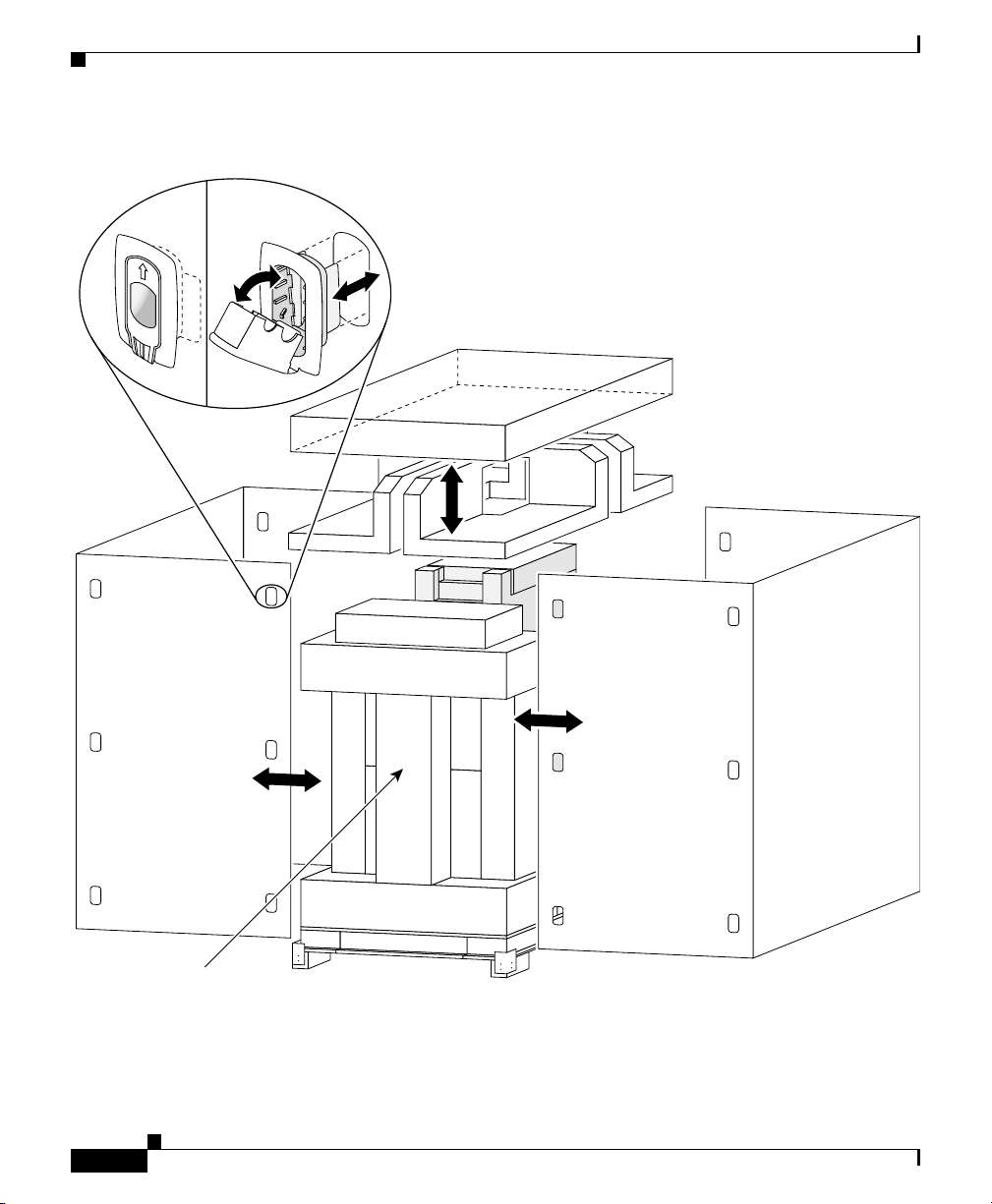
Figure A-7 shows how to install the router and scissor-jack platform on the
shipping pallet.
Figure A-7 Installing the Router and Scissor-Jack Platform on the Pallet
RX
6
E
L
O
S
N
O
C
X
T
E
U
S
A
E
R
1
0
-
T
T
O
O
L
L
S
S
T
C
E
J
E
CARRIER
TX
ACTIVE
T
/L
O
C
RX
A
RX
5
5
2
TX
TX
IER
RX
RX CELL
RX
CARR
4
R
O
4
RX PKT
N
ACTIVE
0
I
M
TX
R
CARRIER
O
TX
J
T
A
K
M
P
ACTIVE
L
R
X
A
E
R
I
IC
R
T
I
R
RX
R
A
C
RX
C
E
V
I
T
3
C
A
3
1
TX
TX
RX
RX
2
2
RX PKT
TX
RRIER
TX
CA
ACTIVE
RX
RX
1
1
TX
TX
0
RX
RX
0
0
TX
TX
CDHNT CD
CDHNT CD
LOOP RA LA
DOWN
LOOP RA LA
DOWN
29186
Pallet body
A-16
Pallet front bar
Top view of pallet parts
Cisco XR 12416 Router Chassis Installation Guide
OL-xxxxx-xx
Page 17

Appendix A Repackaging the Router
REVIEW DRAFT—CISCO CONFIDENTIAL
To reinstall the router and scissor-jack platform on the shipping pallet, use
Figure A-7 as a reference and follow these steps:
Step 1 Use the hand truck to move the chassis to a level, open space with a solid floor.
Step 2 Tilt the chassis upright so that it stands on the scissor-jack platform, then remove
the hand truck.
Step 3 Use the bolts from the original shipping package to attach the eight hold-down
brackets to the sides of the scissor-jack platform (two brackets on each side).
Note The hold-down brackets are not symmetrical: The bracket plate that
fastens to the side of the scissor-jack platform is narrower than the bracket
plate that fastens to the top of the pallet, and has smaller diameter bolt
holes.
Step 4 Position the U-shaped pallet body behind the scissor-jack platform with the
opening facing the back panel of the router.
Step 5 Use the 3/4-inch (19-mm) socket and ratchet wrench to turn the scissor-jack screw
slowly counterclockwise to expand the scissor-jack platform and raise the top of
the scissor-jack platform high enough for the hold-down brackets to clear the top
of the pallet body.
Step 6 Slide the pallet body around the scissor-jack platform.
Step 7 Slide the pallet front bar into the opening on the pallet body and use the hinge
locks to secure it as instructed in these steps:
Repackaging the Routers
OL-xxxxx-xx
a. Pivot the butterfly handle on the hinge lock up so that it is perpendicular to
the body of the hinge lock.
b. Twist the butterfly handle counterclockwise to extend the hinge lock hook to
its maximum reach.
c. Lower the hinge lock hook over the hinge lock catch on the pallet body.
d. Twist the butterfly handle clockwise to clamp the hinge lock hook on the
hinge lock catch on the pallet body.
e. Pivot the butterfly lever down onto the hinge lock body so that it lies flat.
Cisco XR 12416 Router Chassis Installation Guide
A-17
Page 18

Repackaging the Routers
REVIEW DRAFT—CISCO CONFIDENTIAL
Step 8 Shift the pallet to ensure that it is positioned evenly all the way around the
Step 9 Turn the scissor-jack screw slowly clockwise to close the scissor-jack platform
Step 10 Set a blocking plate into the hold-down bracket so that the blank side of the
Step 11 Insert bolts through each of the hold-down bracket holes and into the holes in the
Step 12 Turn the scissor-jack screw slowly clockwise to collapse the scissor-jack platform
Appendix A Repackaging the Router
scissor-jack platform and the bolt holes in the hold-down brackets on the sides of
the scissor-jack platform are aligned with the holes in the top of the shipping
pallet.
and lower the top of the scissor-jack platform slowly until the hold-down brackets
touch the top of the shipping pallet.
blocking plate is against the heads of the bolts in the side of the scissor-jack
platform and the open holes in the blocking plate align with the bolt holes in the
top of the pallet.
top of the shipping pallet, then use the 9/16-inch (14-mm) wrench to tighten the
bolts.
and raise the base of the scissor-jack platform until the weight of the router and
scissor-jack platform is absorbed by the pallet. Continue turning the scissor-jack
screw clockwise to close the scissor-jack platform and lift the base of the
scissor-jack platform until the scissor-jack platform is completely closed (the
screw can not be turned).
A-18
Cisco XR 12416 Router Chassis Installation Guide
OL-xxxxx-xx
Page 19

Appendix A Repackaging the Router
REVIEW DRAFT—CISCO CONFIDENTIAL
Reinstalling Components in the Router
If you elected to remove components from the chassis before removing it from the
rack, you must now reinstall all the components in the chassis.
Reinstalling the Cards in the Upper and Lower Card Cages
Reinstall all of the cards from the upper and lower card cages in their original
slots.
• Reinstall all of the cards in the upper card cage as instructed in the
“Reinstalling the Cards in the Upper Card Cage” section on page 3-52.
• Reinstall all of the cards in the lower card cage as instructed in the
“Reinstalling the Cards in the Lower Card Cage” section on page 3-53.
Caution Any unoccupied card slot in the upper or lower card cages must have a blank filler
panel installed for electromagnetic compatibility (EMC) and to ensure proper air
flow through the chassis. When the faceplate of a line card does not completely
fill the card slot opening, a narrow card filler panel must be installed for
electromagnetic compatibility (EMC) and to ensure proper air flow through the
chassis.
Repackaging the Routers
Reinstalling the Cards in the Switch Fabric Card Cage
Reinstall all of the cards from the switch fabric card cage in their original slots as
instructed in the “Reinstalling the Cards in the Switch Fabric Card Cage” section
on page 3-50.
Replacing the Blower Modules
Replace the blower modules as instructed in the “Reinstalling the Blower
Modules” section on page 3-47.
Reinstalling the Power Modules
If you removed AC-input power supplies from the chassis, reinstall each power
supply as instructed in the “Installing AC-Input Power Supplies” section on
page 3-75.
OL-xxxxx-xx
Cisco XR 12416 Router Chassis Installation Guide
A-19
Page 20

Repackaging the Routers
REVIEW DRAFT—CISCO CONFIDENTIAL
If you removed DC-input power entry modules, reinstall each power entry module
as instructed in the “Installing DC-Input Power Entry Modules” section on
page 3-78.
Reinstalling the Front Covers
When the router is repackaged for shipping, two foam inserts must be paced
around the top of the router. To avoid interference with the foam inserts, the front
cover for the power shelf and upper blower module should not be reinstalled on
the router. It must be placed in its original box and packaged in the accessories
boxed.
Reinstall the other front covers as instructed in the “Installing the Front Covers”
section on page 3-39.
Repackaging the Router Accessories
To protect the accessories and the router from damage during shipment, you must
repackage the router accessories in their original packaging and reassemble the
accessories boxes into a package that is packed against the back panel of the
router on the deck of the pallet body.
Appendix A Repackaging the Router
Repackaging the Rack-Mounting Platform
To repackage the rack-mounting platform, follow these steps:
Step 1 Remove the screws that fasten the angle brackets to the sides of the rack-mounting
platform.
Step 2 Place the screws and brackets in a plastic bag.
Step 3 Screw the threaded leveling feet completely into the legs of the platform.
Step 4 Turn the platform on its top and place it in its accessories box.
Step 5 Place the bag of screws and brackets in the accessories box.
Step 6 Place the corrugated pad foam side down on top of the platform.
Step 7 Close and seal the platform accessories box.
Cisco XR 12416 Router Chassis Installation Guide
A-20
OL-xxxxx-xx
Page 21

Appendix A Repackaging the Router
REVIEW DRAFT—CISCO CONFIDENTIAL
Repackaging the Vertical Cable-Management Troughs
To repackage the vertical cable-management troughs, follow these steps:
Step 1 Place the six screws in a plastic bag.
Step 2 Insert the trough into the long plastic bag.
Step 3 Put the foam cap on each end of the trough.
Step 4 Place the trough and the bag of screws into the corrugated carton.
Step 5 Close and seal the carton.
Step 6 Repeat Step 1 through Step 5 for the second trough.
Repackaging the Center-Mount Rack-Mounting Brackets
If you used the optional center-mount rack-mounting brackets to install the router
in the equipment rack, you must repackage the brackets.
To repackage the brackets, follow these steps:
Repackaging the Routers
OL-xxxxx-xx
Step 1 Remove the brackets from the rack and place all of the screws in a plastic bag.
Step 2 Turn the brackets so the screw rails are interlocked.
Step 3 Hold the brackets together and put the two foam caps on the ends of the brackets.
Step 4 Place the brackets and the bag of screws into the corrugated carton.
Step 5 Close and seal the carton.
Cisco XR 12416 Router Chassis Installation Guide
A-21
Page 22

Repackaging the Routers
REVIEW DRAFT—CISCO CONFIDENTIAL
Repackaging the Miscellaneous Accessories
To repackage the all of the miscellaneous accessory pieces, follow these steps:
Step 1 Put the box containing the front cover for the power shelf and upper blower
module into the large miscellaneous accessories box.
Step 2 Put all of the other miscellaneous accessory pieces in the box.
Step 3 Close and seal the carton.
Reassembling the Accessories Package
Figure A-2 shows an exploded view of the pieces that make up the accessories
package for the router. To reassemble the accessory box package, use Figure A-2
on page A-5 as a reference and follow these steps:
Step 1 Place the bottom accessories package cap open side up on the floor.
Step 2 To insert the accessory boxes into their slots in the bottom cap, follow these steps:
Appendix A Repackaging the Router
A-22
a. Insert the box containing the center-mount rack-mounting brackets in the
center slot closest to the back panel of the router.
b. Set the box containing the rack-mounting platform against the box containing
the center-mount rack-mounting brackets.
c. Insert one vertical cable-management trough box on either side of the box
containing the rack-mounting platform.
d. Place the miscellaneous accessories box on top of the rack-mounting
platform box, between the two trough boxes.
Step 3 Place the top accessories package cap over the ends of the accessories boxes and
push it down to hold all the boxes together.
Cisco XR 12416 Router Chassis Installation Guide
OL-xxxxx-xx
Page 23

Appendix A Repackaging the Router
REVIEW DRAFT—CISCO CONFIDENTIAL
Completing the Repackaging
To repackage the router, use Figure A-1 on page A-4 as a reference and follow
these steps:
Step 1 Verify that the anchor clips fastening the chassis to the scissor-jack platform are
installed correctly and that the bolts are tight.
Step 2 Verify that the bolts fastening the hold-down brackets to the sides of the
scissor-jack platform and the top of the pallet are tight.
Step 3 Pull the plastic bag over the router to protect it against electrostatic discharge
(ESD) and dust.
Step 4 Place the side of the accessories package with the single box containing the
center-mount rack-mounting brackets against the back panel of the router on the
extended deck of the pallet body.
Step 5 Place the folded corrugated spacer on top of the accessories package, then place
the two foam inserts around the top of the router.
Step 6 To install the U-shaped, corrugated side panels, use Figure A-1 on page A-4 as a
reference and follow these steps:
a. Set the long side of one panel on the pallet base such that it sits inside the
bead-boards attached to the outside corners of the pallet riser blocks and
against the side of the pallet platform.
Repackaging the Routers
OL-xxxxx-xx
b. Set the narrow end flaps of the panel inside the bead-boards attached to the
outside corners of the pallet riser blocks.
c. Position the opposite U-shaped side panel such that one narrow end flap is
inside the narrow end flap of the first U-shaped side panel, while the other
narrow end flap is outside the narrow end flap of the first U-shaped side panel.
Note Because the two U-shaped side panels are identical, interlocking them in
this fashion maintains the correct overall container dimensions and
strength.
Cisco XR 12416 Router Chassis Installation Guide
A-23
Page 24

Repackaging the Replaced Router Chassis
REVIEW DRAFT—CISCO CONFIDENTIAL
Step 7 To fasten the two U-shaped side panels together, use Figure A-1 on page A-4 as a
reference and follow these steps.
a. Starting at one of the top holes on one narrow side panel, align the holes in
the inner and outer corrugated panels.
b. Open a plastic locking clip by pulling the wedge block out of the clip.
c. Insert the clip into the hole, then pivot the wedge block into the opening on
the body of the clip and push firmly until it snaps into place, spreading the
butterfly tabs and locking the inner and out side panels together.
d. Repeat steps a. and c. for the remaining holes on the narrow side panel.
e. Repeat steps a. through d. for the opposite narrow side panel.
Step 8 Set the corrugated top cap on top of the container side panels and push it down.
Step 9 Use a strapping machine to wrap two straps end-to-end and two straps side-to-side
over the top of the shipping container to secure it to the pallet.
Your router is now repackaged and ready to be transported. Use a forklift or pallet
jack to move the repackaged router.
Appendix A Repackaging the Router
Repackaging the Replaced Router Chassis
This section describes how to repackage a defective chassis to return it to the
factory.
Note Because the packaging scheme for a bare chassis is very similar to the packaging
scheme for a fully-equipped router, the process for repackaging a bare chassis is
very similar to the process of packaging a fully-equipped router.
Cisco XR 12416 Router Chassis Installation Guide
A-24
OL-xxxxx-xx
Page 25

Appendix A Repackaging the Router
Repackaging the Replaced Router Chassis
REVIEW DRAFT—CISCO CONFIDENTIAL
This section contains the following information and procedures:
• The Router Replacement Chassis Shipping Container, page A-25
• Tools and Equipment, page A-25
• Safety Recommendations, page A-25
• Reinstalling the Replaced Chassis on the Shipping Pallet, page A-25
• Repackaging the Replaced Chassis for Shipment, page A-26
The Router Replacement Chassis Shipping Container
Except for the difference in the foam cushion that sits between the top of the bare
chassis, the shipping container for the bare chassis is very similar to the shipping
container shown in Figure A-1 on page A-4 and described in the “The Router
Shipping Package” section on page A-2, earlier in this appendix.
Tools and Equipment
For a list of the items needed to repackage the replaced chassis, refer to the “Tools
and Equipment” section on page A-25, earlier in this appendix.
Safety Recommendations
For a summary of the safety information you should review before you begin the
procedures in this section, refer to the “Safety Recommendations” section on
page A-25, earlier in this appendix.
Reinstalling the Replaced Chassis on the Shipping Pallet
Reinstall the replaced chassis and scissor-jack platform on the shipping pallet as
described in the “Installing the Router on the Shipping Pallet” section on
page A-16, earlier in this appendix.
Cisco XR 12416 Router Chassis Installation Guide
OL-xxxxx-xx
A-25
Page 26

Appendix A Repackaging the Router
Repackaging the Replaced Router Chassis
REVIEW DRAFT—CISCO CONFIDENTIAL
Repackaging the Replaced Chassis for Shipment
Repackage the replaced chassis for shipment as described in the “Completing the
Repackaging” section on page A-23, earlier in this appendix.
A-26
Cisco XR 12416 Router Chassis Installation Guide
OL-xxxxx-xx
 Loading...