

Cisco SR520-FE-K9, SRP521W-K9-G1, SRP521W-K9-G5, SRP526W, SRP521W Administration Manual
...Page 1
Cisco SRP500 Series Services Ready Platforms
(SRP520 Models)
ADMINISTRATION
GUIDE
Page 2

Cisco and the Cisco Logo are trademarks of Cisco Systems, Inc. and/or its affiliates in the U.S. and other countries. A listing of Cisco's trademarks can be found
at www.cisco.com/go/trademarks. Third party trademarks mentioned are the property of their respective owners. The use of the word partner does not imply
a partnership relationship between Cisco and any other company. (1005R)
© 2012 Cisco Systems, Inc. All rights reserved. 78-20691-01
Page 3

Contents
Chapter 1: Introducing the SRP500 Series Services Ready Platform (SRP520
Models) 10
Feature Overview 10
Product Overview 11
Model Numbers 11
Front Panel 11
SRP521W Front Panel 11
SRP526W / SRP527W Front Panel 12
Front Panel Lights 12
Back Panel 13
SRP521W Back Panel 13
SRP526W / SRP527W Back Panel 13
Back Panel Descriptions 14
Side View 15
Top View 16
Default Settings 17
Chapter 2: Getting Started with the Configuration Utility 18
Logging In to the Configuration Utility 18
Overview of the Configuration Utility 19
Main Window Areas 19
Configuration Utility Icons 20
Chapter 3: The Quick Setup Menu 21
Basic Configuration Setup 21
WAN Setup (Ethernet) 21
WAN Setup (ADSL) 22
LAN Setup 22
Wireless Setup 22
Remote Provisioning 23
Advanced Configuration Setup 23
Voice 23
Mobile Network Setup 23
Cisco SRP500 Series Services Ready Platforms Administration Guide (SRP520 Models) 3
Page 4

Contents
Firewall 23
NAT 24
Chapter 4: Setting up the Interfaces of the Services Ready Platforms 25
Setting up the WAN Interface 25
Internet Setup 26
Adding a Subinterface 29
Encapsulation Settings 32
IPoA Settings 32
PPPoE Settings 33
PPPoA Settings 34
Internet Options 35
Mobile Network 36
Failover and Recovery 40
Setting up the VLAN Interfaces and LAN Ports 42
DHCP Server 42
VLAN Settings 45
Port Settings 47
Setting up the Wireless LAN 48
Basic Wireless Settings 49
Wireless Protected Setup 55
WPS Method 1 55
WPS Method 2 56
WPS Method 3 56
Wireless MAC Filter 56
Advanced Wireless Settings 58
WMM Setting 61
Using the Management Interface 61
Chapter 5: Configuring the Network 62
Routing 63
Static Routes 63
RIP 64
Cisco SRP500 Series Services Ready Platforms Administration Guide (SRP520 Models) 4
Page 5

Contents
Intervlan Routing 66
NAT 66
NAT Setting 66
Port Forwarding 67
Port Range Triggering 69
QoS 71
QoS Bandwidth Control 71
QoS Policy 72
CoS To Queue 74
DSCP To Queue 75
Firewall 75
Firewall Filter 75
Internet Access Control 77
PPPoE Relay 79
DDNS 80
DMZ 82
IGMP 83
UPnP 84
CDP Setting 85
Chapter 6: Configuring Voice 87
Configuring Voice Services 87
Understanding Voice Port Operations 87
SRP Voice Features 88
Supported Codecs 88
SIP Proxy Redundancy 89
Other SRP Voice Features 90
Registering to the Service Provider 95
Managing Caller ID Services 97
Optimizing Fax Completion Rates 99
Silence Suppression and Comfort Noise Generation 101
Cisco SRP500 Series Services Ready Platforms Administration Guide (SRP520 Models) 5
Fax Troubleshooting 100
Page 6

Contents
Configuring Dial Plans 102
About Dial Plans 102
Digit Sequences 102
Digit Sequence Examples 104
Acceptance and Transmission the Dialed Digits 106
Dial Plan Timer (Off-Hook Timer) 107
Syntax for the Dial Plan Timer 107
Examples for the Dial Plan Timer 108
Interdigit Long Timer (Incomplete Entry Timer) 108
Syntax for the Interdigit Long Timer 109
Example for the Interdigit Long Timer 109
Interdigit Short Timer (Complete Entry Timer) 109
Syntax for the Interdigit Short Timer 109
Examples for the Interdigit Short Timer 109
Editing Dial Plans 110
Entering the Line Interface Dial Plan 110
Resetting the Control Timers 110
Secure Call Implementation 111
Enabling Secure Calls 111
Secure Call Details 112
Using a Mini-Certificate 113
Generating a Mini Certificate 114
Configuring Voice Settings 115
Info Page 115
Product Information 115
System Status 116
Line Status 117
System Page 119
System Configuration 119
Miscellaneous Settings 119
SIP Page 120
SIP Parameters 120
SIP Timer Values 123
Response Status Code Handling 125
RTP Parameters 125
SDP Payload Types 127
NAT Support Parameters 128
Provisioning Page 131
Cisco SRP500 Series Services Ready Platforms Administration Guide (SRP520 Models) 6
Configuration Profile 131
Page 7

Contents
Firmware Upgrade 134
General Purpose Parameters 135
Regional Page 136
Defining Ring and Cadence and Tone Scripts 136
Call Progress Tones 138
Distinctive Ring Patterns 141
Distinctive Call Waiting Tone Patterns 141
Distinctive Ring/CWT Pattern Names 142
Ring and Call Waiting Tone Spec 144
Control Timer Values (sec) 144
Vertical Service Activation Codes 147
Vertical Service Announcement Codes 153
Outbound Call Codec Selection Codes 153
Miscellaneous 154
Line Pages (1–2) 156
Line Enable 157
Streaming Audio Server (SAS) 157
NAT Settings 158
Network Settings 159
SIP Settings 160
Call Feature Settings 164
Proxy and Registration 166
Subscriber Information 168
Supplementary Service Subscription 169
Audio Configuration 171
Dial Plan 176
FXS Port Polarity Configuration 177
177
User Pages (1–2) 178
Chapter 7: Configuring VPN 183
IKE Policy 183
IPSec Policy 185
Cisco SRP500 Series Services Ready Platforms Administration Guide (SRP520 Models) 7
Call Forward Settings 178
Selective Call Forward Settings 179
Speed Dial Settings 179
Supplementary Service Settings 180
Distinctive RIng Settings 182
Ring Settings 182
Page 8

Contents
GRE Tunnel 188
VPN Passthrough 190
Cisco VPN Server 191
Configuring Users 194
Chapter 8: Administration Settings 195
Web Access Management 196
Remote Management 197
TR069 197
SNMP 199
SNMP Port Descriptions 200
Local TFTP 201
Time Setup 202
Setup Wizard 203
User List 204
User Privilege Control 204
Logging 205
Factory Defaults 206
Firmware Upgrade 206
Backup & Restore 207
Backup Configuration 207
Restore Configuration 207
Reboot 208
Status 208
Switch Setting 208
Chapter 9: Using Services Ready Platform Diagnostics 210
Ping Test 210
Traceroute Test 211
Detect Active LAN Clients 211
Cisco SRP500 Series Services Ready Platforms Administration Guide (SRP520 Models) 8
Page 9

Contents
Chapter 10: Viewing the Services Ready Platforms Status 212
Router Settings 213
Firewall Status 214
Interface Information 216
Wireless Network Status 217
Wireless Client Information 218
Mobile Network Status 218
DHCP Server Information 220
QoS Status 221
Routing Table 222
ARP Table 222
RIP Status 223
IGMP Status 223
VPN Status 224
CDP Neighbor Information 225
Appendix A: Specifications 226
Appendix B: Where to Go From Here 228
Cisco SRP500 Series Services Ready Platforms Administration Guide (SRP520 Models) 9
Page 10

Introducing the SRP500 Series Services
Ready Platform (SRP520 Models)
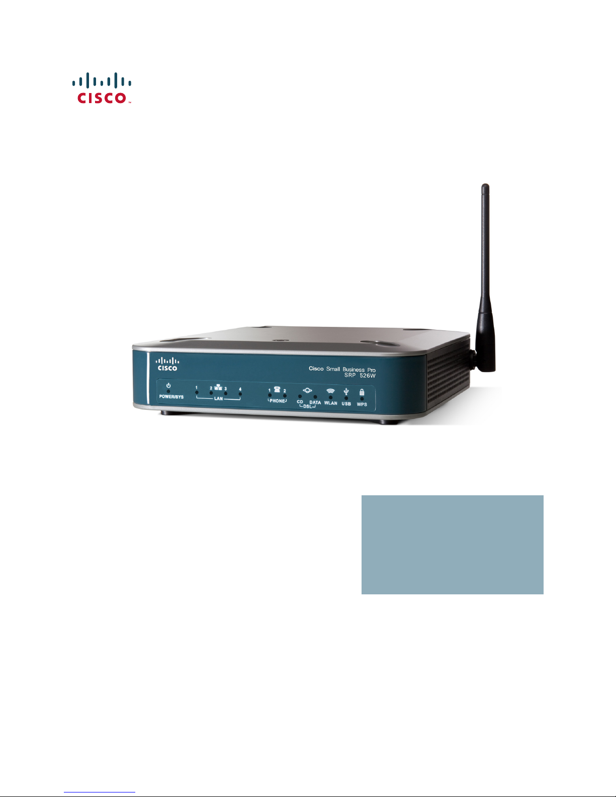
Thank you for choosing the Cisco SRP500 Series Services Ready Platforms
(SRP520 Models). The SRP500 Series are flexible devices that enable small
businesses to connect to a variety of services (high quality data, hosted voice, and
security services) offered by service providers.
This chapter provides information to familiarize you with the product. It consists of
these sections:
• Feature Overview
• Product Overview
1
For information about how to physically install the SRP and how to use the Setup
Wizard to initially configure it, see the Cisco SRP500 Series Services Ready
Platforms Quick Start Guide (SRP520 Models) at
www.cisco.com/go/srp500resources.
Feature Overview
Thank you for choosing the Cisco Services Ready Platform SRP 500 Series
(SRP520 Models).
The SRP 500 Series platforms includes these features:
• Intelligence to support voice, data, security, and application services.
• Industry-leading Session Initiation Protocol (SIP) stack to deliver clear, high-
• Interoperability with popular soft switches and voice gateways.
• Integrated security, VPN capabilities, and an 802.11n wireless access point.
quality voice service.
• Standards-based provisioning for streamlined deployments.
Cisco SRP500 Series Services Ready Platforms Administration Guide (SRP520 Models) 10
Page 11
Introducing the SRP500 Series Services Ready Platform (SRP520 Models)
276377
LANPOWER/SYS
PHONE USB WPSWLANWLAN
Cisco Small Business Pro
SRP 521W
12 2143
Product Overview
Product Overview
This section lists the available model numbers to help you become familiar with
your SRP, and shows the front panel, back panel, and side view of the unit.
Model Numbers
The following table describes the SRP520 Model numbers:
Model Description
SRP521W Fast Ethernet WAN
2 Phone (FXS) ports, 1 Line (FXO) port, 1 WAN (10/100) port,
4 LAN (10/100) ports, 1 USB 2.0 port, 802.11n, and WiFi Protected
Setup (WPS)
1
SRP526W ADSL2+ Annex B (ADSL over ISDN)
2 Phone (FXS) ports, 1 Line (FXO) port, 1 DSL port,
4 LAN (10/100) ports, 1 USB 2.0 port, 802.11n, and WiFi Protected
Setup (WPS)
SRP527W ADSL2+ Annex A/M (ADSL over POTS)
2 Phone (FXS) ports, 1 Line (FXO) port, 1 DSL port,
4 LAN (10/100) ports, 1 USB 2.0 port, 802.11n, and WiFi Protected
Setup (WPS)
Front Panel
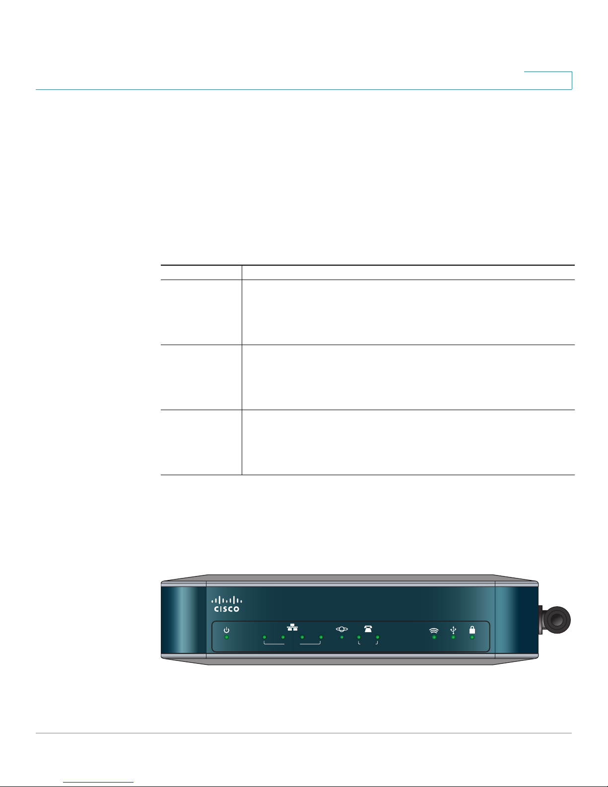
SRP521W Front Panel
Cisco SRP500 Series Services Ready Platforms Administration Guide (SRP520 Models) 11
Page 12
Introducing the SRP500 Series Services Ready Platform (SRP520 Models)
LANPOWER/SYS
PHONE
CD Data
DSL
USB WPSWLAN
Cisco Small Business Pro
SRP 526W
12 2143
Product Overview
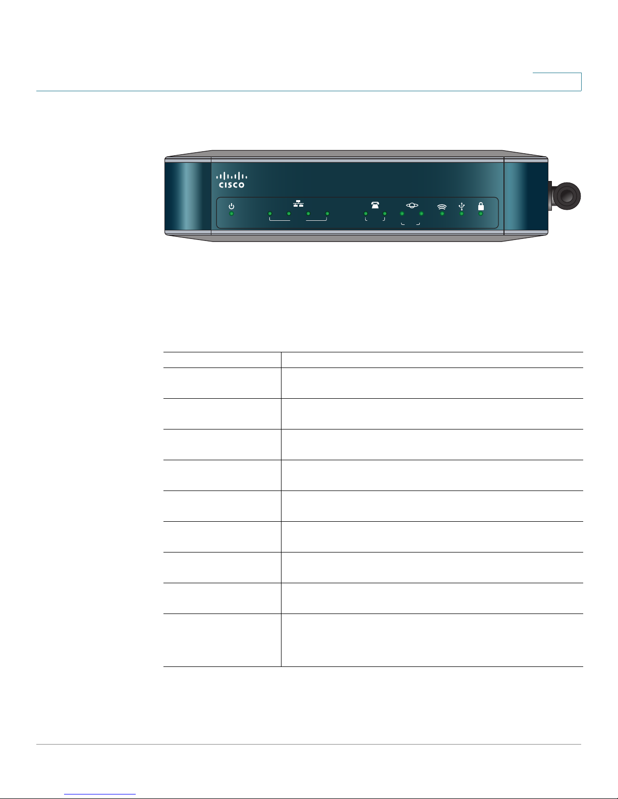
SRP526W / SRP527W Front Panel
Front Panel Lights
The following table describes the lights on the front panel of the SRP. These lights
are used for monitoring system activity.
1
Lights (Green) Description
POWER/SYS Lights when the SRP has successfully booted and is
ready to use. Flashes when the SRP is booting.
LAN ports (1–4) Lights when a link is established. Flashes when there is
activity on the LAN port.
WAN por t
(SRP521W only)
Phone (FXS) ports
(1– 2)
Lights when a link established. Flashes when there is
activity on the WAN port.
Lights when a link is established. Flashes when there is
activity on the Phone port.
DSL CD Flashes when a DSL service is detected. Lights solid
green when synchronized.
DSL Data
(SRP 526W/527W only)
Flashes when there is DSL activity on the line.
WLAN Lights when the radio is powered on and operational.
Flashes when there is wireless activity on the WLAN port.
USB port Lights when the connected USB device is operational.
Flashes if there is a device failure or unsupported device.
WPS button Lights when WiFi Protected Setup (WPS) is operational.
A slow green flash indicates that the setup is in progress.
A fast green flash indicates a setup error.
Cisco SRP500 Series Services Ready Platforms Administration Guide (SRP520 Models) 12
Page 13
Introducing the SRP500 Series Services Ready Platform (SRP520 Models)
236278
LAN (10/100)LAN/WAN
21 1234
LINE (FXO)DSL PHONE (FXS)
On/Off
Switch
Line
(FXO)
Por t
DSL
Por t
Phone
(FXS)
Por ts
LAN
Por ts
12 V DC
power
Product Overview
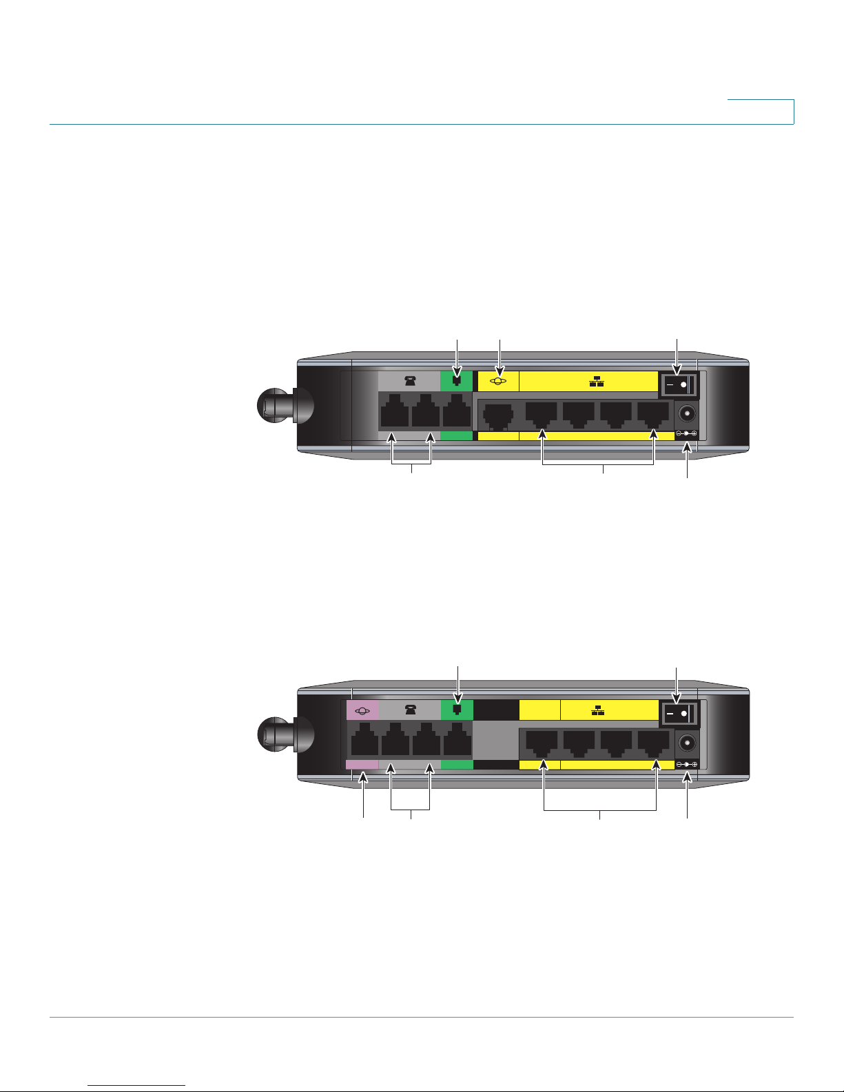
Back Panel
The back panel is where you connect the network devices. The ports on the panel
vary depending on the model.
SRP521W Back Panel
1
Line
(FXO)
21 1234
LINE (FXO)PHONE (FXS)
Phone
(FXS)
Por ts
WAN
Por t
SRP526W / SRP527W Back Panel
Por t
LAN (10/100)WAN (10/100)
LAN
Por ts
On/Off
Switch
12VDC
236282
12 V DC
power
Cisco SRP500 Series Services Ready Platforms Administration Guide (SRP520 Models) 13
Page 14

Introducing the SRP500 Series Services Ready Platform (SRP520 Models)
Product Overview
Back Panel Descriptions
Feature Description
DSL port
SRP526/SRP527W only
Phone (FXS) ports (1–2) Connect directly to an analog telephone, fax machine,
Line (FXO) port Connects to a PSTN, which is the analog telephone
Connects the SRP to your DSL connection.
or similar device.
If your analog phone requires a separate bell line (as is
often the case in the UK), you might need to connect a
ring adapter between the SRP and your phone so that
the phone rings when calls are presented.
service network that a traditional telephone service
uses.
1
WAN (10/100) port
SRP521W only
LAN (10/100) ports (1–4) Connects to a wired computer and other network
On/Off Switch Powers the SRP on or off.
12 V DC power Connects to the provided power adapter.
Connects the SRP to your Wide-Area-Network (WAN).
devices.
Cisco SRP500 Series Services Ready Platforms Administration Guide (SRP520 Models) 14
Page 15

Introducing the SRP500 Series Services Ready Platform (SRP520 Models)
236283
RESET
Reset
Button
USB
Connector
Product Overview
Side View
1
Antenna
236284
Feature Description
Reset button Press and hold for 5 seconds to reset the SRP. Press and
hold for 10 seconds to reset the SRP to its factory defaults.
To press the button, insert a paper clip or similar object into
the opening
.
USB port Connects to a compatible USB Modem.
For information about connecting the SRP to a USB see
Mobile Network, page 36.
Antenna The WiFi antenna.
Cisco SRP500 Series Services Ready Platforms Administration Guide (SRP520 Models) 15
Page 16
Introducing the SRP500 Series Services Ready Platform (SRP520 Models)
Product Overview
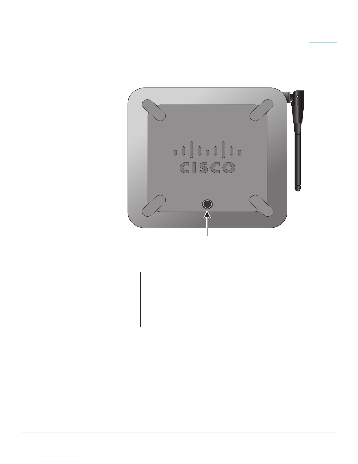
Top V i ew
1
276378
WPS Button
Feature Description
WPS Button Use to automatically configure wireless security for devices
that support WiFi Protected Setup (WPS).
To configure WPS, press and hold this button until the WPS light
flashes. Make sure that the device is located near the SRP during
setup.
Cisco SRP500 Series Services Ready Platforms Administration Guide (SRP520 Models) 16
Page 17

Introducing the SRP500 Series Services Ready Platform (SRP520 Models)
Product Overview
Default Settings
Parameter Value
Device IP 192.168.15.1
Username cisco
Password cisco
Admin Username admin
Admin Password admin
DHCP Range 192.168.15.100 to 149
Data VLAN VLAN 1
Voice VLAN VLAN 100, published to the Cisco VOIP phones via CDP
1
Cisco SRP500 Series Services Ready Platforms Administration Guide (SRP520 Models) 17
Page 18

2
Getting Started with the Configuration Utility
This chapter describes how to configure and use the Services Ready Platform
Configuration Utility. This is a web-based utility you use to manage and provision
your SRP (Services Ready Platform).
This chapter includes the following sections:.
• Logging In to the Configuration Utility
• Overview of the Configuration Utility
Logging In to the Configuration Utility
This section describes how to log in to Services Ready Platform Configuration
Utility.
STEP 1 Connect a computer to an available LAN port of your SRP.
By default, your PC will become a DHCP client of the SRP and will receive an IP
address in the 192.168.15.x range.
STEP 2 Start a web browser.
In the Address bar, enter http://192.168.15.1. This is the default address of the SRP.
STEP 3 When the login window opens, enter the username and password to login as the
administrator.
The default username is admin.
The default password is admin.
NOTE Passwords are case sensitive.
NOTE If you log in as cisco (with password of cisco), the Setup Wizard will automatically
begin. if you log in as admin, you can start the Setup Wizard by clicking
Administration > Setup Wizard.
Cisco SRP500 Series Services Ready Platforms Administration Guide (SRP520 Models) 18
Page 19
Getting Started with the Configuration Utility
Overview of the Configuration Utility
STEP 4 Click Log In. The Services Ready Platform Configuration Utility opens.
Overview of the Configuration Utility
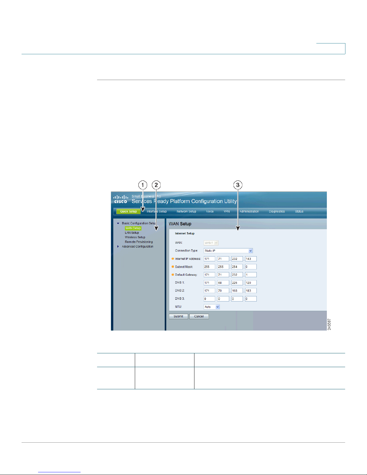
Main Window Areas
This section describes the Main menu bar areas and icons that the Configuration
Utility uses.
2
Number Component Description
1
Cisco SRP500 Series Services Ready Platforms Administration Guide (SRP520 Models) 19
Menu Bar Contains the major function categories. Click a
menu item to change to another category.
Page 20

Getting Started with the Configuration Utility
Overview of the Configuration Utility
Number Component Description
2
2
Navigation Pane Provides easy navigation through the
configurable device features.The main
branches expand to provide the subfeatures.
Click on the triangle next to the main branch title
to expand or contract its contents. Click on the
title of a feature or subfeature to open it.
3 Main Content The main content of the feature appears in this
area.
Configuration Utility Icons
The Configuration Utility has icons and buttons for commonly used configuration
options. The following table describes these icons:
Icon Description
Edit Icon The Edit icon lets you edit an existing item from a list.
After making your changes, click the Submit button to
save your changes.
Add Item
Icon
Delete Item
Icon
Increment
Decrement
Icons
The Add Item icon lets you add an item to a list. After
you have created a new item, click the Submit button to
save the new item.
The Delete Item icon lets you delete an item from a list.
After you have deleted an item, click the Submit button
to save your changes.
The Increment and Decrement icons let you change
numeric values. Click the “+” icon to increment a value;
click the “-” icon to decrement a value. Click the Submit
button to save your changes.
Cisco SRP500 Series Services Ready Platforms Administration Guide (SRP520 Models) 20
Page 21

The Quick Setup Menu
This chapter describes how to use the Quick Setup Menu to set up the essential
connectivity features for your Services Ready Platforms. It includes the following
sections:
• Basic Configuration Setup
• Advanced Configuration Setup
The Quick Setup menu is displayed by default when you first logon to the SRP. You
can use these setup pages to quickly get the device up and running. The menu
also provides convenient links to features found in the Configuration Utility.
To a c c e s s t he s e pa ge s c l i ck Quick Setup > Basic Configuration Setup from the
Configuration Utility menu bar.
3
Basic Configuration Setup
Use the Basic Configuration Setup to configure WAN, LAN, Wireless, and Remote
Provisioning settings for your SRP.
To a c c e s s t he s e pa ge s c l i ck Quick Setup > Basic Configuration Setup from the
Configuration Utility.
WAN Setup (Ethernet)
Use the WAN Setup page to quickly setup your Ethernet WAN interface.
STEP 1 Click Quick Setup > WAN Se tup. The WAN Set up window opens.
STEP 2 Enter your Internet connection type as required by your Internet Service Provider
(ISP).
STEP 3 Specify the Connection Type Settings as described in Adding a Subinterface,
page 29.
Cisco SRP500 Series Services Ready Platforms Administration Guide (SRP520 Models) 21
Page 22

The Quick Setup Menu
Basic Configuration Setup
STEP 4 Click Submit to save your settings.
STEP 1 Click Quick Setup > WAN Set up.
STEP 2 The WAN S etup window opens.
STEP 3 Enter your VC and IP settings as defined in Internet Setup, page 26,
STEP 4 Click Submit to save your settings.
3
WAN Setup (ADSL)
Use the WAN Setup page to quickly setup your ADSL WAN interface.
LAN Setup
Use the LAN Setup page to quickly setup the LAN interface.
STEP 1 Click Quick Setup > LAN Setup. The LAN Setup window opens.
STEP 2 Enter the Router IP and DHCP server settings for the LAN. For detailed
descriptions of these fields, see the DHCP section under Setting up the VLAN
Interfaces and LAN Ports, page 42.
STEP 3 Click Submit to save your settings.
Wireless Setup
Use the Wireless Setup page to quickly setup the Wireless network.
STEP 1 Click Quick Setup > Wireless Setup. The Wireless Setup window opens.
STEP 2 Specify the wireless network settings as described in Basic Wireless Settings,
page 49.
STEP 3 Click Submit to save your settings.
Cisco SRP500 Series Services Ready Platforms Administration Guide (SRP520 Models) 22
Page 23

The Quick Setup Menu
Advanced Configuration Setup
Remote Provisioning
Use the TR-069 page to configure communication with an Auto-Configuration
Server (ACS) through the TR-069 CPE WAN Management Protocol (CWMP).
STEP 1 Click Quick Setup > Remote Provisioning. The Remote Provisioning window
opens.
STEP 2 Click Enabled to enable remote provisioning.
STEP 3 Specify the remote provisioning settings as defined in Remote Management,
page 197.
STEP 4 Click Submit to save your settings.
3
Advanced Configuration Setup
The features in Advanced Configuration Setup lets you configure advanced
settings with Voice, Mobile Network Setup, the Firewall, and NAT.
To access this page click Quick Setup > Advanced Configuration Setup from the
Configuration Utility.
Voice
Use the Voice option to administer and view voice service and settings. For more
details, see Configuring Voice, on page 87.
Mobile Network Setup
Use the Voice option to administer and view voice service and settings. For more
details, see Mobile Network, on page 36.
Firewall
The Firewall option lets you administer the firewall filter settings. For more details,
refer to Firewall, on page 75.
Cisco SRP500 Series Services Ready Platforms Administration Guide (SRP520 Models) 23
Page 24

The Quick Setup Menu
Advanced Configuration Setup
NAT
Use the NAT option to administer the NAT (Network Address Translation) settings.
For more details, see NAT, on page 66.
3
Cisco SRP500 Series Services Ready Platforms Administration Guide (SRP520 Models) 24
Page 25

Setting up the Interfaces of the Services
Ready Platforms
This chapter describes how to set up the interfaces for your SRP. It includes the
following sections:
• Setting up the WAN Interface
• Setting up the VLAN Interfaces and LAN Ports
• Setting up the Wireless LAN
• Using the Management Interface
To a c c e s s t he s e pa ge s c l i ck Interface Setup from the Configuration Utility menu
bar.
4
Setting up the WAN Interface
This section describes how to configure the WAN interface settings for the SRP
including:
• Internet Setup
• Encapsulation Settings
• Mobile Network
• Failover and Recovery
To access these pages click Interface Setup > WAN from the Configuration Utility.
Cisco SRP500 Series Services Ready Platforms Administration Guide (SRP520 Models) 25
Page 26

Setting up the Interfaces of the Services Ready Platforms
Setting up the WAN Interface
Internet Setup
Use the Internet Setup page to configure the settings for WAN networking.
NOTE After you configure the interface settings, we recommend that you create a new
password for your SRP. To change it, see User List, page 204. Taking this
precaution increases security by protecting the SRP from unauthorized changes.
STEP 1 Click Interface Setup > WAN > Internet Setup. The Internet Setup window
opens.
The WAN Interface List shows the default route, interface type, type of Internet
connection, and Internet IP address for each interface.
STEP 2 To configure the WAN Interface settings, click the WAN interface link under the
Interface column.
4
STEP 3 Configure the parameters for the physical interfaces.
• For a DSL interface, choose a DSL protocol from the drop-down list. If you
know what to use, or if the SRP has trouble detecting the right modulation,
specify a modulation type. The default DSL modulation is MultiMode
(recommended).
• For an Ethernet interface, select the flow control setting (enabled by
default), interface speed and duplex settings (the default is Auto-negotiate),
or override the MAC address used by the interface. To use the MAC
address from the PC being used to configure the SRP, click Clone Your
PC's MAC.
STEP 4 Configure the Interface Addressing.
a. From the WAN interface list, click the Edit (pencil) icon next to the interface that
you want to configure.
The Internet Setup settings for the interface window opens.
b. Specify the VC settings as defined in the VC Settings table below.
Depending on the encapsulation type that you choose, the available options
may change the other options that appear on this page. For more information,
see Encapsulation Settings, page 32.
c. Click Submit to save your changes.
Cisco SRP500 Series Services Ready Platforms Administration Guide (SRP520 Models) 26
Page 27

Setting up the Interfaces of the Services Ready Platforms
Setting up the WAN Interface
VC Settings
Field Description
Multiplexing Defines the way in which different protocols are
handled within a DSL virtual circuit. You an choose
between Logical Link Control (LLC) encapsulation (also
called LLC-SNAP) or Virtual Channel (VC) multiplexing
(also called VC-Mux).
QoS Type Select the DSL Quality of Service (QoS) method that
your ISP uses on your line: Unspecified Bit Rate (UBR),
Constant Bit Rate (CBR), Real-Time Variable Bit Rate
(RTVBR), or Non-Real-Time Variable Bit Rate (NRTVBR).
CBR provides the best guarantee of low latency; UBR
provides none, but is typically used for most broadband
data services.
4
Pcr Rate—When QoS is set to CBR, VBR_RT, or VBR_NRT,
•
enter the Peak Cell Rate (PCR) in cells per second.
• Scr Rate—When QoS is set to VBR_NRT or VBR_RT, enter
the Sustained Cell Rate (SCR) in cells per second.
• MBS—When QoS is set to VBR_NRT or VBR_RT, enter the
MBS in cells per second.
• CDVT—When QoS is set to CBR, VBR_NRT or VBR_RT,
enter the CDVT in cells per second.
VPI/VCI Auto Detect Use to enable or disable automatic detection of the VPI
and VCI values that identify your line to the ATM
network. The Virtual Path Identifier (VPI) and Virtual
Channel Identifier (VCI) are values used to identify your
line to your ISP's ATM network. The SRP will
automatically detect DSL services offered on the
following VC pairs: 1/32, 0/38, 0/35, 8/35, 0/43, 0/51,
0/59, 8/43, 8/51, 8/5.
STEP 5 To configure an Ethernet subinterface, click the Edit (pencil) icon next to the WAN
interface. Enter the settings as described in Adding a Subinterface, page 29.
STEP 6 Select the default route for the interface you are configuring. The default route for
voice is Default Voice Route.
Cisco SRP500 Series Services Ready Platforms Administration Guide (SRP520 Models) 27
Page 28

Setting up the Interfaces of the Services Ready Platforms
Setting up the WAN Interface
NOTE When using the interface failover feature, the Interface Default Route automatically
selects the subinterface that is used to pass traffic redirected from a failed
interface.
STEP 7 To view the interface information, select a WAN interface from the WAN Interface
List. The WAN Interface Detail area displays information about the interface as
described in the table below.
WAN Interface Detail Settings
Name Value
Link Status Interface status; connected or disconnected.
4
IP Address Public IP address of the interface.
Netmask Subnet mask.
Gateway IP address of the ISP server.
Host Name Hostname, if applicable.
Domain Name Domain name, if applicable.
MTU Type Auto or Custom.
MTU Size Current MTU size. This value is blank if set to Auto.
DNS 1,2,3 IP addresses of the DNS servers, if configured.
VLAN
Encapsulation
VLAN ID VLAN ID used if VLAN Encapsulation is enabled.
If enabled, a IEEE 802.1q VLAN header is added to outbound
traffic, allowing some Service Providers to control quality of
service based on associated IEEE 802.1p priority values.
Cisco SRP500 Series Services Ready Platforms Administration Guide (SRP520 Models) 28
Page 29

Setting up the Interfaces of the Services Ready Platforms
Setting up the WAN Interface
Adding a Subinterface
Use the WAN Interface List page from the Internet Setup window to add a
subinterface to the SRP. These options are the same as those for configuring a
main WAN interface except you cannot configure an Ethernet subinterface for
PPTP or L2TP.
The SRP supports multiple logical interfaces per physical port. For Ethernet ports,
VLAN interfaces are created as part of an IEEE 802.1p trunk. Multiple PVCs may be
created on ADSL interfaces.
The SRP supports up to 5 VLANS which can be used as either Local Area VLANs
or WAN subinterfaces. Up to four PVCs can be configured on an ADSL interface.
STEP 1 To add a new logical Internet connection, select the top level WAN from the
Internet Setup page and click the Add (page) icon. The Internet Setup window for
the new Internet connection opens.
4
STEP 2 Choose the connection type required by your Internet Service Provide (ISP) as
defined in the Ethernet WAN Interface Settings table.
STEP 3 Choose an MTU option from the drop-down list. Unless a change is required by
your ISP, we recommend that you set the MTU method to Auto, which allows the
voice system to automatically choose the size. The default size is 1500 bytes.
To specify another MTU size, choose Custom from the drop-down list and enter
the size in bytes. The standard size for Ethernet networks is 1500 bytes. For
PPPoE connections, the standard size is 1492 bytes.
STEP 4 Click Submit to save your changes.
The new connection is added to the WAN Interface List on the Internet Setup
page.
Cisco SRP500 Series Services Ready Platforms Administration Guide (SRP520 Models) 29
Page 30

Setting up the Interfaces of the Services Ready Platforms
Setting up the WAN Interface
Ethernet WAN Interface Settings
Field Description
WAN WAN1 is the interface identity for the SRP’s WAN port. This
value cannot be changed.
VLAN ID VLAN identity for the interface or subinterface. This value
cannot be changed after the interface is first created.
Connection Type Type of Internet connection that your ISP provides.
Automatic Configuration/DCHP
Connection type often used with cable modems. Choose
this option if your ISP dynamically assigns an IP address on
connection. No other information is required for this
connection type.
4
Static IP
Choose this option if your ISP provides you with a static
(permanent) IP address and does not assign it dynamically.
Enter the assigned IP Address, Subnet Mask, and Default
Gateway IP address.
Cisco SRP500 Series Services Ready Platforms Administration Guide (SRP520 Models) 30
Page 31

Setting up the Interfaces of the Services Ready Platforms
Setting up the WAN Interface
Ethernet WAN Interface Settings
Field Description
PPPoE
Choose this option if your ISP uses PPPoE (Point-to-Point
Protocol over Ethernet).
Enter the User Name and Password for your ISP account
and the Service Name if required by your ISP. Select either
the Connect on Demand or Keep Alive option.
Connect on Demand
Opens a connection only when a user attempts to connect
to the Internet. The connection automatically terminates if
there is a period of inactivity longer than the specified Max
Idle Time (in minutes). We recommend this option if your
billing is based on the time that you are connected.
4
NOTE PCs often send information to the Internet even if email or
a web browser is not being used. This may keep the session
connected for longer than expected.
Keep Alive
Keeps you connected to the Internet indefinitely, even when
your connection sits idle.
PPTP
Select this option if your ISP uses PPTP (Point to Point
Tunneling Protocol).
Enter the PPTP Server IP address and the User Name and
Password for your account.
If your service provider does not dynamically assign an IP
address, disable DHCP and enter the address, mask and
gateway details provided for your account.
Select either the Connect on Demand or Keep Alive
option.
Cisco SRP500 Series Services Ready Platforms Administration Guide (SRP520 Models) 31
Page 32

Setting up the Interfaces of the Services Ready Platforms
Setting up the WAN Interface
Ethernet WAN Interface Settings
Field Description
L2TP
Select this option if your ISP uses L2TP (Layer 2 Tunneling
Protocol) and has provided you with a static IP address.
Enter the L2TP Server IP address and the User Name and
Password for your account.
If your service provider does not dynamically assign an IP
address, disable DHCP and enter the address, mask and
gateway details provided for your account.
Select either the Connect on Demand or Keep Alive
option.
4
Maximum
Transmission Unit
(MTU)
Static DNS 1-3 (Optional) Enter the IP addresses of up to three Domain
Size, in bytes, of the largest packet that can be sent through
the network. This value is typically1500 bytes but might
need to be lower for some broadband services. Check with
your service provider for specific requirements.
Name System (DNS) servers, or leave the fields blank to
allow a DNS server to be assigned dynamically.
Encapsulation Settings
This section describes the ADSL Encapsulation Settings that you can choose from
in the Internet Setup page under VC settings.
Encapsulation is the protocol used between your broadband gateway and your
ISP's servers. Most of the encapsulations are defined in Internet standards called
Requests for Comments (RFCs). Two are derived from the Point-to-Point Protocol
(PPP): PPP over Ethernet (PPPoE) and PPP over ATM (PPPoA).
IPoA Settings
Choose IPoA for direct encapsulation of IP traffic over the DSL ATM virtual circuit.
Enter the required information as provided by your ISP: Internet IP Address,
Subnet Mask, and Default Gateway IP address. Optionally, you can enter the IP
addresses of the primary and secondary DNS servers.
Cisco SRP500 Series Services Ready Platforms Administration Guide (SRP520 Models) 32
Page 33

Setting up the Interfaces of the Services Ready Platforms
Setting up the WAN Interface
IPoA Settings
Field Description
4
Internet IP Address
and Subnet Mask
Default Gateway Your ISP provides you with the Gateway IP Address.
Primary/Secondary
DNS
The SRP’s IP Address and Subnet Mask as seen by
external users on the Internet (including your ISP). Your
ISP provides you with this information.
Use to define one or two DNS servers. The SRP uses
these to resolve domain names for locally configured
features and may also pass these on to local clients
through DHCP.
PPPoE Settings
Choose PPPoE to run Ethernet encapsulated PPP over the DSL ATM virtual circuit.
Enter the user name and password provided to you by your ISP. Optionally, you
can also specify a PPP service name, if one is provided by your service provider.
PPPoE Settings
Field Description
Username and
Password
Service Name String required by some ISPs. Fill this in only if your ISP
Connect on
Demand
Cisco SRP500 Series Services Ready Platforms Administration Guide (SRP520 Models) 33
Strings that your ISP has instructed you to use. The user
name can be called a “username,” “login name,” or
“login.”
requires it.
Connects the broadband gateway to your ISP when a
connection is needed and disconnects it when the line
to your ISP is idle for a given amount of time
You can also adjust the maximum idle time; the default
setting is 20 minutes. The alternative to Connect on
Demand is Keep Alive (see next). In most cases you can
choose either option without consulting your ISP.
Page 34

Setting up the Interfaces of the Services Ready Platforms
Setting up the WAN Interface
PPPoE Settings
Field Description
Keep Alive Maintains the connection to your ISP all the time. If the
link goes down for a given number of seconds (the
“redial period”), the gateway automatically tries to reestablish it. The default redial period is 20 seconds.
4
Enable MTU/MRU
greater than 1492
LCP Echo-Request
Interval
Extra header information used on PPPoE connections
over ADSL that limits the maximum packet size that can
be sent to 1492 bytes. Enable this setting only if
instructed to do so by your ISP.
Specify the LCP Echo Interval in seconds. The default
is 30 seconds. This determines how often the SRP
sends an LCP echo request at regular intervals to the
ISP to ensure that the PPPoE connection is active.
PPPoA Settings
Choose PPPoA to run PPP directly over the DSL ATM virtual circuit. Enter the user
name and password provided by your ISP.
PPPoA Settings
Field Description
User name and
Password
Strings that your ISP has instructed you to use. The user
name may be called a “username,” “login name,” or
“logon.”
Connect on
Demand
Keep Alive Maintains the connection to your ISP all the time. If the
Cisco SRP500 Series Services Ready Platforms Administration Guide (SRP520 Models) 34
Connects the broadband gateway to your ISP when a
connection is needed and disconnects it when the line
to your ISP is idle for a given amount of time. Connection
and disconnection are automatic. You can also adjust
the maximum idle time; the default setting is 20 minutes.
The alternative to Connect on Demand is Keep Alive
(see next). In most cases you can choose either option
without consulting your ISP.
link goes down for a given number of seconds (“redial
period”), the gateway automatically tries to re-establish
it. The default redial period is 20 seconds.
Page 35

Setting up the Interfaces of the Services Ready Platforms
Setting up the WAN Interface
Internet Options
Use the Internet Options page to supplement the information configured for your
Internet connection.
STEP 1 Click Interface Setup > WAN > Internet Option. The Internet Option window
opens.
STEP 2 Enter the Host Name and Domain Name if provided by your ISP.
STEP 3 Enter the IP addresses for up to three DNS servers.
NOTE The SRP allows DNS server information to be specified in a number of different
contexts, allowing you to meet your specific needs.
Each WAN interface allows either the static or dynamic configuration of primary,
secondary and tertiary connection specific servers. You can also statically
configure primary, secondary and tertiary servers globally under Internet Options.
4
To determine which servers to use for internal name resolution, the SRP takes the
first three addresses from a list that it constructs in the following order:
• Primary servers from Internet Options WAN1, WAN2, and then 3G.
• Secondary servers from Internet Options WAN1, WAN2, and then 3G.
• Tertiary servers from Internet Options WAN1, WAN2, and then 3G.
STEP 4 Click Submit to save your changes.
Internet Options
Field Description
Host Name Hostname provided by your ISP.
Domain Name Domain name provided by your ISP.
Static DNS 1–3 Enter the IP addresses for up to three DNS servers.
Cisco SRP500 Series Services Ready Platforms Administration Guide (SRP520 Models) 35
Page 36

Setting up the Interfaces of the Services Ready Platforms
Setting up the WAN Interface
Mobile Network
Use the Mobile Network page to configure your SRP to connect to a Mobile
Broadband USB modem that is connected to its USB interface. For information
about compatible modems see: www.cisco.com/go/srp500.
STEP 1 Click Interface Setup > Mobile Network. The Mobile Network window opens.
STEP 2 Connect to the USB Modem. If the card is supported by the SRP, it is automatically
detected and appears on the Mobile Network page.
STEP 3 Select Auto or Manual connection mode. The default mode is Auto.
• To enable your modem to establish a connection automatically, select Auto
mode.
• To connect or disconnect your modem connection manually, select Manual
mode.
4
NOTE Ethernet Connection Recovery works only if the Connection Mode is set to Auto. If
you select Auto, you must also select either Connect on Demand or Keep Alive.
STEP 4 Verify that the Card Status field shows the status of your mobile card.
STEP 5 If required, select a tunnelling protocol to configure for the interface.
STEP 6 If necessary, change any mobile network settings in the Mobile Network Setup
area.
NOTE You must click the Manual option in the Configure Mode field to manually setup your
mobile network card.
STEP 7 Click Submit to save your settings
Cisco SRP500 Series Services Ready Platforms Administration Guide (SRP520 Models) 36
Page 37

Setting up the Interfaces of the Services Ready Platforms
Setting up the WAN Interface
Field Description
Connect Mode Choose Auto or Manual Mode. If you are using manual
mode, you will need to access the Configuration Utility
to establish an Internet connection through the mobile
connection. Click Connect to establish a connection
when required. Click Disconnect to tear down the
connection.
NOTE The Ethernet Connection Recovery and Interface
Connection Failover works only if the Connection Mode is set
to Auto. If you select Auto, you must also select Connect on
Demand and Keep Alive.
4
Connect on
Demand
Tunnel Protocol The Tunnel Protocol (PPTP/L2TP) is supported through
Select this option to enable the SRP to terminate the
Internet connection after it is inactive for a specified
period of time (Max Idle Time). If your Internet
connection is terminated due to inactivity, this option
allows the modem to automatically re-establish a
terminated connection when a user attempts to access
the Internet again.
In the Max Idle Time field, enter the number of minutes of
idle time that can elapse before your Internet connection
terminates. The default Max Idle Time is 5 minutes.
a USB modem by one of these methods.
• NONE. Select this option to disable protocol
tunneling.
• PPTP/L2TP. Select PPTP or L2TP depending on
the service that you want to use. You must also
provide the server IP address, user name, and
password.
• Follow Ethernet WAN configure. Select this
option to make the Tunnel Protocol follow the
configuration of the Ethernet WAN.
Cisco SRP500 Series Services Ready Platforms Administration Guide (SRP520 Models) 37
Page 38

Setting up the Interfaces of the Services Ready Platforms
Setting up the WAN Interface
Field Description
4
Card Status
Displays the current modem connection status as
initializing, connecting, connected, disconnecting, or
disconnected.
These messages might also appear:
• Please set APN manually
Appears when the SRP is unable to determine the
APN from the operator in automatic mode.
• Searching for service...
• no SIM card
• SIM locked
• SIM busy
• SIM ready
• pin code needed
• pin code error
• Card is locked
• Card is not activated
• Card initialized error
• error
NOTE If Connect Mode is set to Manual, you can click a
button to connect or disconnect your modem.
Configure Mode
Card Model Data card model that is inserted into the USB drive.
Access Point Name
(APN)
The SRP automatically detects supported modems and
presents a list of appropriate default configurations. If
you need to override any of these settings (with the
exception of the SIM PIN), select manual configuration
mode.
Unsupported cards are reported as unrecognized.
Internet network to which the mobile device is
connecting to. Enter the access point name provided by
your mobile network service provider.
Cisco SRP500 Series Services Ready Platforms Administration Guide (SRP520 Models) 38
Page 39

Setting up the Interfaces of the Services Ready Platforms
Setting up the WAN Interface
Field Description
Dial Number Dial number for the Internet connection. Enter the Dial
Number provided by your mobile network service
provider.
4
User Name/
Password
SIM PIN PIN code associated with your SIM card. Enter your SIM
Server Name Name of the server for the Internet connection if
Authentication Type of authentication used by your service provider.
Service Type Select the most commonly available type of mobile data
User name and password provided by your mobile
network service provider.
PIN number here. This field is only displayed for GSM
cards.
provided by your service provider.
Choose your authentication type from the drop-down
list. The default is Auto. If you don’t know which type of
authentication to use, keep the default setting.
service connection based on your area service signal. If
your location supports only one mobile data service,
you may wish to limit your preferred option, which may
enhance connection setup times. The first selection
always searches for HSPDA/3G/UMTS service or
switches to GPRS automatically only when it is
available.
Cisco SRP500 Series Services Ready Platforms Administration Guide (SRP520 Models) 39
Page 40

Setting up the Interfaces of the Services Ready Platforms
Setting up the WAN Interface
Failover and Recovery
An Internet connection can be established through the WAN port or a wireless
modem plugged into the USB port. See www.cisco.com/go/srp500 for more
details on compatible USB modem devices.
While both Ethernet and a USB modem may be connected, only one can be used
to establish a link at a time. Whenever the Internet connection fails, the SRP
automatically attempts to bring up another connection on another interface. This
feature is called Failover. When the original Internet connection is restored, reverts
to using this path and drops the backup connection. This feature is called
Recovery.
STEP 1 Click Interface Setup > Failover & Recovery. The Failover & Recovery window
opens.
STEP 2 Click Enabled to enable Connection Recovery.
4
When enabled, the SRP sets the Ethernet interface to the highest priority and also
enables Interface Connection Failover. If the Internet connection fails, the SRP
automatically attempts to bring up the mobile network connection on the USB
interface (if available). Whenever the Internet connection recovers, the SRP
automatically reverts to using this instead of the backup interface.
NOTE Mobile Connection Mode must be set to Auto to use Ethernet Connection Recovery.
STEP 3 Enter a failover timeout value.
STEP 4 Choose a site on which to perform failover validation in the Failover Validation Site
area. Either use the next hop gateway or enter the IP address for a custom site.
STEP 5 Change the priority of the WAN interfaces by clicking the Up or Down buttons.
STEP 6 Click Submit to save your settings.
Cisco SRP500 Series Services Ready Platforms Administration Guide (SRP520 Models) 40
Page 41

Setting up the Interfaces of the Services Ready Platforms
Setting up the WAN Interface
Failover and Recovery Settings
Field Description
4
Connection
Recovery
Interface
Connection Failover
Timeout Time interval at which the SRP detects the status of the
Connection
Validation Site
WAN Interfaces Provides information on current status of the Ethernet
Enable to ensure that your primary internet connection
in backed up.
Failover detection works by detecting the physical
connection and/or presence of traffic on the Internet
link. If the link is idle, the SRP attempts to ping a
destination. If the ping does not reply, the SRP assumes
the link is down and attempts to fail over to another
interface.
Internet connection. The default timeout interval is 60
seconds.
Ping target for the SRP to use to detect the status of the
Internet connection. By default the SRP pings the
Network Time Protocol (NTP) servers. You may specify
a different IP address as a target here.
Internet connection and Mobile Network connection.
Click the Status hyperlink to view the details.
You can also configure the interface priority by clicking
Up or Down. Note that the interface priority setting is
configurable only when Ethernet Connection Recovery
is disabled.
STEP 7 aces by clicking the Up or Down buttons.
STEP 8 Click Submit to save your settings.
Cisco SRP500 Series Services Ready Platforms Administration Guide (SRP520 Models) 41
Page 42

Setting up the Interfaces of the Services Ready Platforms
Setting up the VLAN Interfaces and LAN Ports
Setting up the VLAN Interfaces and LAN Ports
This section describes how to set up the SRP VLAN and LAN ports. It includes the
following sections:
• DHCP Server
• VLAN Settings
• Port Settings
To access these pages click Interface Setup > LAN from the Configuration Utility.
DHCP Server
To configure the SRP as a DHCP server, you must first create a DHCP server by
using the DHCP Server page and then enable it by assigning it to a VLAN interface.
4
NOTE When creating a DHCP server you must also specify the IP address and mask for
the VLAN interface it is assigned to. If you do not assign a DHCP Server to a VLAN
interface, then the IP addressing options are configured directly through the VLAN
settings.
Use the DHCP Server page to create DHCP lease pools, reserve leases for
specific hosts, define default routing and set DHCP option values.
STEP 1 Click Interface Setup > LAN > DHCP Server. The DHCP Server window opens.
STEP 2 To view the information for a DHCP entry, click one of the items in the DHCP List.
The DHCP information displays in the DHCP Details table.
STEP 3 To add or delete a DHCP entry from the DHCP list, click the Edit (pencil) or Delete
(x) icon.
STEP 4 To create a new DHCP Server Pool, click Add Entry. The DCHP Server window for
the new entry opens.
STEP 5 Under Router IP, enter the DHCP Name and Local IP Address/Subnet Mask.
STEP 6 Configure the DHCP Server Settings as defined in the DHCP Server Settings
table.
STEP 7 Click Submit to save your settings.
Cisco SRP500 Series Services Ready Platforms Administration Guide (SRP520 Models) 42
Page 43

Setting up the Interfaces of the Services Ready Platforms
Setting up the VLAN Interfaces and LAN Ports
DHCP Server Settings
Field Description
Router IP
DHCP Name Label which identifies this DHCP Server configuration
and is used to assign the service to a VLAN interface.
4
Local IP Address/
Subnet Mask
DHCP Server Setting
Show DHCP
Reservation button
WAN In te rfa ce
Option 66 Provides provisioning server address information to
IP address and subnet mask used to configure the
VLAN interface to which this DHCP rule is applied.
Click this button to review and modify the DHCP
reservations. Click the button again to hide the
reservation tables.
Choose the WAN Interface from which the related DHCP
information, specifically DNS, is obtained.
hosts requesting this option. Server information can be
defined in one of three ways:
• Local TFTP Server: The SRP uses its own TFTP
server to source provisioning files so it returns its
own local IP address to the client.
• Remote TFTP Server: If the SRP was configured
by using this method, it uses the server
information it received through option 66 on its
WAN interface in response to local client
requests.
Cisco SRP500 Series Services Ready Platforms Administration Guide (SRP520 Models) 43
• Manual TFTP Server: Allows the manual
configuration of a configuration server address.
While this option is typically used to provide
either an IP address or a fully qualified hostname,
the SRP will also accept and offer a full URL
including protocol, path and filename to meet the
requirements of specific clients.
Page 44

Setting up the Interfaces of the Services Ready Platforms
Setting up the VLAN Interfaces and LAN Ports
DHCP Server Settings
Field Description
Option 67 Provides a configuration/bootstrap filename to hosts
requesting this option. This is used in conjunction with
option 66 to allow the client to form an appropriate TFTP
request for the file.
4
DNS Proxy
Starting IP Address IP address of the first address in this pool.
Maximum DHCP
Users
If DNS proxy is enabled, local clients are offered the
SRP Local IP Address to use for DNS requests. The SRP
then proxies these requests to the DNS servers it was
configured with. See the note about DNS in Internet
Setup, page 26.
If DNS proxy is disabled, then DHCP clients will be
offered DNS server information based on the following:
• If the Static DNS field is configured, then that server
alone will be offered to clients.
• If the Static DNS field is not configured up to three
servers are offered, first from the global Internet
Options static configuration and then from the WAN
interface nominated above.
Maximum number of devices that you want the DHCP
server to assign IP addresses to. This number is
affected by the subnet mask and starting IP address. It
cannot be greater than 1024. The default is 50.
IP Address Range Displays the range of DHCP addresses.
Client Lease Time Amount of time an address is leased to a client. Enter
Static DNS Defines a DNS server address that DHCP clients use
Window Internet
Naming Service
(WINS)
Cisco SRP500 Series Services Ready Platforms Administration Guide (SRP520 Models) 44
the amount of time, in minutes, for the lease. The default
is 0 minutes, which means one day.
directly for name resolution. This option is only required
when the DNS proxy feature is disabled for this DHCP
server. The field is hidden when DNS proxy is enabled.
Manages the window’s host name to address resolution.
If you use a WINS server, enter the IP address of the
server. Otherwise, leave this field blank.
Page 45

Setting up the Interfaces of the Services Ready Platforms
Setting up the VLAN Interfaces and LAN Ports
VLAN Settings
VLAN settings are configured on this page. After clicking Add Entry, you can
create another VLAN.
STEP 1 Click Interface Setup > LAN > VLAN Setting. The VLAN Setting window opens.
From this page you can view the list of configured VLANs, add or delete a VLAN,
and view the details for a selected VLAN.
STEP 2 To edit or delete a VLAN entry from the DHCP list, click the Edit (pencil) or Delete
(x) icon.
STEP 3 To view the information for a VLAN entry, click any of the items in the VLAN Details
List.The VLAN information for the DHCP Pool displays in the VLAN Details table.
STEP 4 To create a new VLAN, click Add Entry. The VLAN Settings window for the new
VLAN opens.
4
STEP 5 Specify the VLAN settings for the new entry as defined in the VLAN Settings
table.
STEP 6 Click Submit to save your settings.
STEP 7 Click Add Entry to open the VLAN Add page. From this page you can add a VLAN
entry.
STEP 8 Click Submit to save your settings.
Cisco SRP500 Series Services Ready Platforms Administration Guide (SRP520 Models) 45
Page 46

Setting up the Interfaces of the Services Ready Platforms
Setting up the VLAN Interfaces and LAN Ports
VLAN Settings
Field Description
VLAN Name Bridge or VLAN name.
VLAN ID Bridge or VLAN ID.
Voice VLAN Click this box if you want to use voice. Only use this
option in VLAN mode.
4
Address Type
Available Interface
Added Interface Interfaces that were selected as members of the VLAN
Address type determines the way in which the VLAN IP
interface is configured.
Choose None if an IP interface is not required. This would
•
typically be the case when bridging ports only.
• Choose Static IP Address to manually define an address
for the interface.
• Choose Dynamic IP Address to request an address from
a DHCP server on the local network.
• Choose DHCP server to enable a previously configured
DHCP Server service on this interface. In this case, the
VLAN IP address will be derived from the DHCP Server
configuration.
Interfaces available to be added to the VLAN. To mo ve
an interface to the Added Interface list, click the
interface, and then click the right-arrow button (>). To
move all of the interfaces at once, click the double
right-arrow button (>>).
bridge.
interface and then click the left arrow button (<). To
remove all of the interfaces at once, click the double
left-arrow button (<<).
To remove an interface from this list, click the
Cisco SRP500 Series Services Ready Platforms Administration Guide (SRP520 Models) 46
Page 47

Setting up the Interfaces of the Services Ready Platforms
Setting up the VLAN Interfaces and LAN Ports
Port Settings
Use the Port Settings page to set the LAN port attributes, edit the port settings, or
view the port settings.
STEP 1 Click Interface Setup > LAN > Port Setting. The Port Setting window opens.
STEP 2 Specify the flow control and speed duplex settings as defined in the Port
Settings table. You can only configure these settings for LAN ports 1–4.
STEP 3 To view the port information, click any of the items in the Port List. The port
information is displayed in the Port Details table.
STEP 4 To edit a port entry, click the Edit (pencil) icon. The VLAN Port Settings window
opens.
STEP 5 Specify the port settings as defined in the Port Settings table.
4
STEP 6 Click Submit to save your settings.
Port Settings
Field Description
Mode Describes the currently configured behavior of the port.
Desktop mode: Provides attached devices with access to
•
a single data VLAN for which the SRP provides DHCP
services. Incoming traffic from the host can be tagged or
untagged. Outgoing traffic to the host will be untagged.
• IP Phone + Desktop mode: The port is configured with a
data VLAN for native access and a voice VLAN for use
with an attached IP Phone. CDP is used to communicate
voice VLAN information to the phone.
Cisco SRP500 Series Services Ready Platforms Administration Guide (SRP520 Models) 47
Page 48

Setting up the Interfaces of the Services Ready Platforms
Setting up the Wireless LAN
Port Settings
Field Description
4
Enabled Flow
Control
Speed Duplex Choose the duplex mode. You can select from Auto-
Port Details Shows detailed information about the ports.
Setting up the Wireless LAN
Mechanism for temporarily stopping the transmission of
data on this physical interface.
For example: A situation might arise where a sending
station (computer) is transmitting data faster than some
other part of the network (including the receiving
station) can accept. The overwhelmed network element
will send a PAUSE frame, which halts the transmission of
the sender for a specified period of time.
To enable this feature, check the box. The default setting
is Disabled.
negotiate, 10 Half, 10 Full, 100 Half and 100 Full. The
default is Auto-negotiate.
This sections describes how to configure the wireless LAN settings for the SRP. It
includes the following sections:
• Basic Wireless Settings
• Wireless Protected Setup
• Wireless MAC Filter
• Advanced Wireless Settings
• WMM Setting
To access these pages click Interface Setup > Wi-Fi Settings from the
Configuration Utility.
Cisco SRP500 Series Services Ready Platforms Administration Guide (SRP520 Models) 48
Page 49

Setting up the Interfaces of the Services Ready Platforms
Setting up the Wireless LAN
Basic Wireless Settings
Use the Basic Wireless Settings page to the SRP's integrated wireless access
point and up to four wireless networks.
STEP 1 Click Interface Setup > Wi-Fi Settings > Basic Wireless Settings. The Basic
Wireless Settings window opens.
STEP 2 Configure the wireless network settings as defined in the Basic Wireless
Settings table. When you are finished, click Submit to save your settings.
STEP 3 Select the network mode to turn the radio on and click Apply.
STEP 4 Configure the network security settings for each SSID. In the Wireless Table area,
click the Edit link in the Security column. The Wireless Security window opens.
STEP 5 Choose the security mode setting from the drop-down list. The default is
Disabled.
4
When you enable a security mode, a window opens that defines the security
settings for that mode (authentication type, encryption, passphrase, and so on).
Enter the security settings as defined in the Basic Wireless Settings table and
click Submit to save your settings.
You are returned to the Basic Wireless page.
Cisco SRP500 Series Services Ready Platforms Administration Guide (SRP520 Models) 49
Page 50

Setting up the Interfaces of the Services Ready Platforms
Setting up the Wireless LAN
Basic Wireless Settings
Field Description
4
Network Mode
Radio Band Select the wireless bandwidth for your network. There are
Choose the wireless mode based on the type of devices in
your network.
NOTE The wireless access point is disabled by default to ensure
network security. You must select an active network mode to enable
it before configuring further.
• If you have Wireless-N, Wireless-G, and Wireless-B devices in
your network, select Mixed.
• If you have only Wireless-G and Wireless-B devices in your
network, select BG-Mixed.
• If you have only Wireless-N devices, select Wireless-N Only.
• If you have only Wireless-G devices, select Wireless-G Only.
• If you have only Wireless-B devices, select Wireless-B Only.
• If you don’t want to use the integrated wireless access
select Disabled.
point,
three options: Auto, Standard–20MHz Channel, and Wide40MHz Channel. The default is Standard–20MHz Channel.
Wide channel band configuration is available for Wireless-N
networks and clients only. If wide channel mode is selected
for mixed networks, standard channel usage is still available
for Wireless -B and -G clients.
Wide Channel If you selected Wide-40MHz Channel for the Radio Band
Cisco SRP500 Series Services Ready Platforms Administration Guide (SRP520 Models) 50
setting, then this setting will be available for your primary
Wireless-N channel. Select any channel from the drop-down
list. If radio band is selected automatically, the wide channel
is also chosen automatically.
Page 51

Setting up the Interfaces of the Services Ready Platforms
Setting up the Wireless LAN
Basic Wireless Settings
Field Description
4
Standard
Channel
Wireless Table
Wireless
Network Name
(SSID)
If you selected Wide-40MHz Channel or Standard -20MHz
Channel for the Radio Band setting, then this setting will be
available. Select the channel for Wireless-N, Wireless-G, and
Wireless-B networking.
If you selected Wide-40MHz Channel for the Radio Band
setting, then the Standard Channel will be a secondary
channel for Wireless-N. The default is channel 11. If radio
band is selected automatically, the standard channel will also
be chosen automatically.
Name of the network that clients use when connecting to the
network.
By default wireless network is named “cisco-data” and is
connected to the default VLAN. To rename the default
wireless network, enter a unique Wireless Network Name,
which is case-sensitive and must not exceed 32 characters
(use any of the characters on the keyboard).
The second default wireless network has the default name
“cisco-voice” and is bridged to the voice VLAN. To create a
second wireless network, enter a unique Wireless Network
Name in the SSID2 setting. To activate this network, select
Enabled Network.
SSID1/2/3/4 Network name shared among all devices in a wireless
Cisco SRP500 Series Services Ready Platforms Administration Guide (SRP520 Models) 51
NOTE Your ISP or ITSP may be responsible for controlling the
SSID2 settings. Contact your ISP or ITSP for more information.
network. The SRP can support up to four wireless networks.
By default, the first and second wireless networks are
enabled, and you can enable two other wireless networks if
needed.
For each wireless network you need to configure the
Wireless Network Name (SSID), Broadcast Network Name,
and Enable Network option.
Page 52

Setting up the Interfaces of the Services Ready Platforms
Setting up the Wireless LAN
Basic Wireless Settings
Field Description
4
Broadcast
Network Name
Enabled
Network
Field Description
Wireless Security Settings (To access, click the Edit Security button for any
configured SSIDs)
Security Mode Select the security method for your wireless network. The
When wireless clients survey the local area for available
wireless networks, they detect the SSIDs that are broadcast
by nearby wireless networks. If you want to broadcast the
SSID, keep the box checked. If you do not want to broadcast
the SSID, uncheck the box. In this case, wireless users would
have to know the SSID to associate with the network.
To enable the wireless network, check the box. To disable the
wireless network, uncheck the box.
SRP supports these wireless security mode options: WPA
Personal, WPA Enterprise, WPA2 Personal, WPA2 Enterprise,
and WEP. (WPA stands for Wi-Fi Protected Access, which is a
stronger security standard than WEP encryption). WEP
stands for Wired Equivalent Privacy.
If you do not want to use wireless security, keep the default
setting, Disabled. Cisco recommends that you use the
highest level of security that is supported by your client
wireless devices.
WEP Security Mode Settings
WEP Basic encryption method, which is not as secure as WPA.
Authentication
Ty pe
Cisco SRP500 Series Services Ready Platforms Administration Guide (SRP520 Models) 52
WEP may be required if your network devices do not
support WPA.
Choose Auto or Shared Key. With the Auto setting, the
network is open, and any device can join the network with or
without a shared key. Shared Key authentication requires
that the client provides the key that you specify on this page.
Page 53

Setting up the Interfaces of the Services Ready Platforms
Setting up the Wireless LAN
Field Description
Encryption Select a level of WEP encryption, 64-bit,10 hex digits or 128-
bit, 26 hex digits. The default is 64-bit,10 hex digits. Higher
encryption levels offer higher levels of security, but due to
the complexity of the encryption, they may decrease
network performance.
Passphrase Enter a passphrase to automatically generate the WEP keys.
Then click Generate. Valid keys appear.
Key 1-4 If you did not enter a passphrase, enter the WEP key(s)
manually.
If you chose 64-bit WEP encryption, the key must be exactly
5 ASCII or 10 hexadecimal characters in length. If you chose
128-bit WEP encryption, the key must be exactly 13 ASCII or
26 hexadecimal characters in length. Valid hexadecimal
characters are “0” to “9” and “A” to “F”.
4
NOTE The SRP supports a single WEP key for the access point. If
multiple SSIDs are configured with WEP, they must share the same
key.
TX Key Select which TX (Transmit) Key to use. The default is 1.
WPA Personal Mode Settings
WPA Personal Provides stronger wireless security with advanced
encryption (TKIP or AES).
WPA Algorithms WPA supports two encryption methods, TKIP and AES, with
dynamic encryption keys. Select the type of algorithm, AES
or TKIP. The default is TKIP.
WPA Shared
Key
Group Key
Renewal
WPA2 Personal Mode Settings
Enter a passphrase of 8 to 63 characters.
Enter an interval in seconds to specify how often the SRP
changes the encryption keys. The default Group Key
Renewal period is 3600 seconds, which is 1 hour.
WPA2 Personal Provides strong wireless security with advanced encryption
Cisco SRP500 Series Services Ready Platforms Administration Guide (SRP520 Models) 53
(AES or TKIP + AES).
Page 54

Setting up the Interfaces of the Services Ready Platforms
Setting up the Wireless LAN
Field Description
WPA Algorithms WPA2 supports two encryption methods, TKIP and AES,
with dynamic encryption keys. Select the type of algorithm,
AES or TKIP + AES. The default is TKIP + AES.
4
WPA Shared
Key
Group Key
Renewal
WPA and WPA2 Enterprise Settings
WPA Enterprise This option features WPA used in conjunction with a
WPA2
Enterprise
WPA Algorithms WPA and WPA2 support two encryption methods, TKIP and
Enter a Passphrase of 8-63 characters.
Enter an interval in seconds to specify how often the SRP
changes the encryption keys. The default Group Key
Renewal period is 3600 seconds, which is 1 hour.
reachable RADIUS server. If you have two RADIUS servers,
select one to be the primary server and specify a secondary
server to use as a backup.
This option features WPA2 used in conjunction with a
reachable RADIUS server. If you have two RADIUS servers,
select one to be the primary server and use the secondary
server as a backup.
AES, with dynamic encryption keys. Select the type of
algorithm, AES or TKIP. The default for WPA is TKIP. The
default for WPA2 is AES.
Primary RADIUS
Server
Secondary
RADIUS Server
Cisco SRP500 Series Services Ready Platforms Administration Guide (SRP520 Models) 54
•
RADIUS Server: Enter the IP Address of the RADIUS server.
• RADIUS Port: Enter the port number of the RADIUS server. The
default value is 1812.
• Shared Secret: Enter the key shared between the SRP and the
server. The key can include 8 to 63 ASCII characters or 64
hexadecimal characters.
RADIUS Server Address: Enter the IP Address of the RADIUS
•
server.
• RADIUS Port: Enter the port number of the RADIUS server.
• Shared Secret: Enter the key shared between the SRP and the
server. The key can include 8 to 63 ASCII characters or 64
hexadecimal characters.
Page 55

Setting up the Interfaces of the Services Ready Platforms
Setting up the Wireless LAN
Field Description
4
Key Renewal
Timeout
Enter an interval in seconds to specify how often the SRP
changes the encryption keys. The default Group Key
Renewal period is 3600 seconds, which is 1 hour.
Wireless Protected Setup
Use the Wi-Fi Protected Setup page to automatically configure wireless security
for your wireless networks.
NOTE Make sure that the WPS client device is located near the SRP during setup.
STEP 1 Click Interface Setup > Wi-Fi Settings > Wi-Fi Protected Setup. The Wi-Fi
Protected Setup window opens.
STEP 2 To enable WPS for an individual SSID, choose the name of the wireless network
that you want configure from the drop-down list. The default data SSID is ciscodata. The default voice SSID is cisco-voice.
STEP 3 WPS is enabled by default. Select Disabled if you don’t want to use this feature for
the selected VLAN.
STEP 4 Choose a Wi-Fi Protected Setup method. The current Wi-Fi Protected status is
displayed at the bottom of the page.
There are three methods to configure your WiFi settings by using WPS. Use the
method that applies to the client device that you are configuring.
WPS Method 1
Use this method if your client device has a Wi-Fi Protected Setup button.
STEP 1 Click or press the Wi-Fi Protected Setup button on the client device.
STEP 2 Click the Wi-Fi Protected Setup button on this page., or press the Wi-Fi protected
Setup button on the SRP520 top panel, if that was associated with the currently
selected SSID. See Basic Wireless Settings, page 49.
STEP 3 After the client device is configured, click OK. Then refer to your client device or its
documentation for further instructions.
Cisco SRP500 Series Services Ready Platforms Administration Guide (SRP520 Models) 55
Page 56

Setting up the Interfaces of the Services Ready Platforms
Setting up the Wireless LAN
WPS Method 2
Use this method if your client device has a Wi-Fi Protected Setup PIN number.
STEP 1 Enter the PIN number in the field on this page.
STEP 2 Click Register.
STEP 3 After the client device is configured, click OK. Then refer to your client device or its
documentation for further instructions.
WPS Method 3
Use this method if your client device asks for the SRP PIN number.
STEP 1 Enter the PIN number listed on this page. (It is also listed on the label on the bottom
of the SRP.)
4
STEP 2 After the client device is configured, click OK. Then refer to your client device or its
documentation for further instructions.
Wireless MAC Filter
Use the Wireless MAC filter page to specify the MAC addresses of the wireless
devices that are permitted access or are blocked by the SRP.
STEP 1 Click Interface Setup > Wi-Fi Settings > Wireless MAC Filter. The Wireless MAC
Filter window opens.
STEP 2 From the Select a SSID drop-down list, choose the MAC filter settings to apply to
the SSID. The default data is SSID is cisco-data, and the default voice SSID is
cisco-voice.
STEP 3 To filter wireless users by MAC Address, either permitting or blocking access,
select Enable. The default is Disable.
STEP 4 In the Access Restriction area, select either Prevent or Permit.
STEP 5 If the Wireless MAC Filter option is enabled, you can click the Show Client List
button to open the Wireless Client List page. This page shows computers and
other devices currently associated with the wireless network. The list can be
sorted by Client Name, Interface, IP Address, MAC Address, and Status.
Cisco SRP500 Series Services Ready Platforms Administration Guide (SRP520 Models) 56
Page 57

Setting up the Interfaces of the Services Ready Platforms
Setting up the Wireless LAN
STEP 6 Select Save to MAC Address Filter List for any device you want to add to the list
and click Add. To retrieve the most up-to-date information, click Refresh. To exit
this page and return to the Wireless MAC Filter page, click Close.
NOTE Wireless access can be filtered by using the MAC addresses of the wireless
devices transmitting within your network radius.
STEP 7 Click Submit to save your settings.
Wireless MAC Filter Settings
Field Description
Wireless MAC Filter
4
Select a SSID Choose the name of the wireless network that you want
to configure. The default data SSID is cisco-data and the
default voice SSID is cisco-voice.
Enabled/Disabled To filter wireless users by MAC Address, either
permitting or blocking access, select Enabled. The
default is Disabled.
Access Restriction
Prevent Select this option to block wireless access from the
clients that you specify in the MAC Address Table. This
is the default setting.
Permit Select this option to permit wireless access only from
the clients that you specify in the MAC Address Table.
Show Client List Click this button to display a list of computers and other
devices that are connected to this wireless network. To
add a listed client to the MAC Address Table, check the
Save to MAC Address Filter List box and click Add. To
hide the client list, click Hide Client List.
MAC Address Table
01-32 Enter the MAC addresses of the devices whose
Cisco SRP500 Series Services Ready Platforms Administration Guide (SRP520 Models) 57
wireless access you want to block or allow.
Page 58

Setting up the Interfaces of the Services Ready Platforms
Setting up the Wireless LAN
Advanced Wireless Settings
Use the Wireless Settings page to configure advanced wireless functions for the
SRP.
NOTE These settings should only be configured by an experienced administrator. Before
you configure these settings, make sure that wireless is enabled on the SRP. See
Basic Wireless Settings, page 49.
STEP 1 Click Interface Setup > Wi-Fi Settings > Advanced Wireless Settings. The
Advanced Wireless window opens.
STEP 2 To configure the RTS Threshold select an SSID from the drop-down list.
STEP 3 Enter a value in the RTS Threshold field. If you encounter inconsistent data flow,
enter only minor reductions. The default value of 2347 is recommended.
4
STEP 4 Change any settings in the Global Settings area as defined in the Advanced
Wireless Settings table.
Click Submit to save your settings.
Advanced Wireless Settings
Field Description
Advanced Wireless Setup
Select a SSID Choose the name of the wireless network that you want
to configure. The default data SSID is cisco-data. The
default voice SSID is cisco-voice.
RTS Threshold The SRP sends Request to Send (RTS) frames to a
receiving station and negotiates the sending of a data
frame. After receiving an RTS, the wireless station
responds with a Clear to Send (CTS) frame to
acknowledge the right to begin transmission. If you
encounter inconsistent data flow, you can adjust this
threshold. Only minor reduction of the default value,
2347, is recommended. If a network packet is smaller
than the preset RTS threshold size, the RTS/CTS
mechanism will not be enabled. The RTS Threshold
value should remain at its default value of 2347.
Cisco SRP500 Series Services Ready Platforms Administration Guide (SRP520 Models) 58
Page 59

Setting up the Interfaces of the Services Ready Platforms
Setting up the Wireless LAN
Advanced Wireless Settings
Field Description
Global Settings
AP Isolation Isolates all wireless clients and wireless devices from
one another. Wireless devices will be able to
communicate with the SRP but not with other wireless
devices on the network. To use this function, select
Enabled. AP Isolation is disabled by default.
Basic Rate Series of rates at which the SRP can transmit. The SRP
advertises its Basic Rate to the other wireless devices in
your network, so they know which rates will be used
and automatically selects the best rate for transmission.
The default setting is Default, which allows the SRP to
transmit at all standard wireless rates (1-2Mbps,
5.5Mbps, 11Mbps, 18Mbps, and 24Mbps). Other
options are 1-2Mbps, for use with older wireless
technology, and All, which allows the SRP to transmit at
all wireless rates. The Basic Rate is not the actual rate of
data transmission. If you want to specify the SRP’s rate
of data transmission, configure the Transmission Rate
setting.
4
N Transmission Rate Set the data transmission rate depending on the speed
of your Wireless-N networking. Select from a range of
transmission speeds, or select Auto for the SRP to
automatically use the fastest possible data rate and
enable the Auto-Fallback feature. Auto-Fallback
negotiates the best possible connection speed
between the SRP and a wireless client. The default is
Auto.
Transmission Rate Set the data transmission rate depending on the speed
of your wireless network. Select from a range of
transmission speeds, or select Auto for the SRP to
automatically use the fastest possible data rate and
enable the Auto-Fallback feature. Auto-Fallback
negotiates the best possible connection speed
between the SRP and a wireless client. The default is
Auto.
Cisco SRP500 Series Services Ready Platforms Administration Guide (SRP520 Models) 59
Page 60

Setting up the Interfaces of the Services Ready Platforms
Setting up the Wireless LAN
Advanced Wireless Settings
Field Description
4
CTS Protection
Mode
DTIM Interval This value, between 1 and 255, indicates the interval of
Fragmentation
Threshold
The SRP automatically uses CTS (Clear-To-Send)
Protection Mode when your Wireless-N and Wireless-G
products are experiencing severe problems and are not
able to transmit to the SRP in an environment with heavy
802.11b traffic. This function boosts the SRP’s ability to
catch all Wireless-N and Wireless-G transmissions but
can impact performance. The default is Auto.
the Delivery Traffic Indication Message (DTIM). A DTIM
field is a countdown field informing clients of the next
window for listening to broadcast and multicast
messages. When the SRP has buffered broadcast or
multicast messages for associated clients, it sends the
next DTIM with a DTIM Interval value. Its clients hear the
beacons and awaken to receive the broadcast and
multicast messages. The default value is 1.
This value specifies the maximum size for a packet
before data is fragmented into multiple packets. If you
experience a high packet error rate, you may slightly
increase the Fragmentation Threshold. Setting the
Fragmentation Threshold too low may result in poor
network performance. Only minor reduction of the
default value is recommended. In most cases, it should
remain at its default value of 2346.
Beacon Interval Enter a value between 40 and 3500 milliseconds. The
Power Control Choose high, middle, or low to specify the range of the
Cisco SRP500 Series Services Ready Platforms Administration Guide (SRP520 Models) 60
Beacon Interval value indicates the frequency interval of
the beacon. A beacon is a packet broadcast by the SRP
to synchronize the wireless network. The default value
is 100.
wireless network. The default is high, which is a normal
power level.
Page 61

Setting up the Interfaces of the Services Ready Platforms
Using the Management Interface
WMM Setting
Use the WMM Setting page to configure support for Wi-Fi Multimedia (WMM)
devices on your network.
STEP 1 Click Interface Setup > Wi-Fi Settings > WMM Setting. The WMM Setting
window opens.
STEP 2 If you have other devices on your network that support WMM, keep the default
setting Enabled.
STEP 3 In the No Acknowledgement option, select Enabled to disable the
acknowledgement feature, so that the SRP will not resend data if an error occurs.
The default is Disabled.
STEP 4 Click Submit to save your settings.
4
Using the Management Interface
Use the Management Interface page to set the Loopback Interfaces, which can be
used for routing updates and some protocols. You can set up to two loopback
interfaces.
STEP 1 Click Interface Setup > Management Interface. The Management Interface
window opens.
STEP 2 To edit an entry in the List of Loopback Interfaces, click the Edit (pencil) icon.
The Manually Adding Loopback window opens.
STEP 3 Enter the IP Address to use for the loopback interface. The address must not
overlap with any other interface configured on the SRP.
NOTE The IP Address used for the loopback interface assumes a subnet mask of
255.255.255.255.
STEP 4 Click Submit to save your settings.
Cisco SRP500 Series Services Ready Platforms Administration Guide (SRP520 Models) 61
Page 62

Configuring the Network
This chapter describes how to configure the network settings for the Services
Ready Platforms. It includes the following sections:
• Routing
• NAT
• Port Range Triggering
• Firewall
• PPPoE Relay
• DDNS
5
• IGMP
• UPnP
• CDP Setting
To access these pages click the Network Setup Tab from the Configuration Utility
menu bar.
Cisco SRP500 Series Services Ready Platforms Administration Guide (SRP520 Models) 62
Page 63

Configuring the Network
Routing
Routing
5
This section describes how to configure various types of routing on the SRP
including:
• Static Routes
• RIP
• Intervlan Routing
To access these pages click Network Setup > Routing from the Configuration
Utility.
Static Routes
Use the Static Routes page to configure static routes for network traffic.
STEP 1 Click Network Setup > Routing > Static Routes. The Static Routes window
opens.
From this page you can view the current static routing list and details of the
selected route, or add another route to the Static Routing List.
STEP 2 To add a static route, click Add Entry.
The Static Routing window for the new entry opens.
STEP 3 Enter a name for the new route.
STEP 4 Enter the destination IP address and subnet mask for the specified network or host
to which want to assign a static route.
STEP 5 Enter the IP address of the gateway that allows for contact between the SRP and
the specified network or host.
STEP 6 Choose the interface for this route.
STEP 7 Click Submit to save your changes.
Cisco SRP500 Series Services Ready Platforms Administration Guide (SRP520 Models) 63
Page 64

Configuring the Network
Routing
5
Static Route Settings
Field Description
Enter Route Name
Destination Subnet IP Address of the network or host to which you want
Subnet Mask Determines which portion of an IP address is the
Gateway IP address of the gateway device that allows for
Interface Determines if the Destination IP Address is on the
Enter a name for the static route.
to assign a static route.
network portion, and which portion is the host
portion.
contact between the SRP and the network or host.
LAN and Wireless (internal wired and wireless
networks), or the Internet (WAN).
RIP
Use the Routing Information Protocol (RIP) pages to configure dynamic routing on
the SRP. You can enable this protocol to allow the specified interfaces to
automatically adjust to physical changes in the network's layout and to exchange
routing tables with other router’s. The SRP determines the network packets' route
based on the fewest number of hops between the source and destination.
STEP 1 Click Network Setup > Routing > RIP. The RIP window opens.
STEP 2 To enable RIP (Dynamic Routing) select Enabled. The default is Disabled.
STEP 3 If RIP is enabled, select the RIP version and timeout values as defined in the RIP
Settings table.
The SRP allows you to define which networks will participate in the routing
protocol either by interface or IP address subnet.
STEP 4 Click Submit to save your settings.
Cisco SRP500 Series Services Ready Platforms Administration Guide (SRP520 Models) 64
Page 65

Configuring the Network
Routing
5
RIP Settings
Field Description
RIP List Interface: Displays the list of interfaces.
RIP Enabled: Select to enable or disable RIP on the interface.
Passive Mode: With the passive mode interface, all receiving
packets are processed as normal and do not send either
multicast or unicast RIP packets except to RIP neighbors. To
select passive mode, select Enabled from the RIP Config Edit
window.
Authentication: If you are sending and receiving RIP Version 2
packets, you can select a RIP authentication on an interface.
The SRP supports two modes of authentication on an interface:
Simple Password Authentication and MD5 Authentication.
NOTE: RIP Version 1 does not support authentication.
RIP Version To limit the types of packets that can be transmitted, choose
Version 1 or Version 2. Alternatively
both Version 1 and Version 2 packets to be transmitted.
RIP Timer RIP uses timers to regulate its performance. These include a
routing-update timer, a route-timeout timer, and a route-flush
timer.
Update: Specify the rate at which the SRP sends routing
updates. The default is 30 seconds.
Timeout: Specify the rate at which the SRP expects to receive
routing updates from each router in the routing table. If this
value is exceeded, the route is declared unreachable. The route
is not removed from the routing table until the route flush timer
expires.
Flush: Specify the maximum period that the SRP will wait for an
update before removing a route from the routing table.
RIP By Select whether you want to enable RIP by interface or by IP
Subnet.
, choose RIP v1/v2 to allow
RIP List Displays the RIP settings all SRP interfaces. To edit the settings,
Cisco SRP500 Series Services Ready Platforms Administration Guide (SRP520 Models) 65
click the Edit (pencil) icon.
Page 66

Configuring the Network
NAT
NOTE Intervlan routing does not apply to the Guest VLAN if you have configured wireless
STEP 1 Click Network Setup > Routing > Intervlan Routing. The Intervlan Routing window
STEP 2 To enable Intervlan Routing, select Enabled. This is the default setting. To disable
STEP 3 Click Submit to save your changes if required.
5
Intervlan Routing
Configuring VLANs helps control the size of the broadcast domain and keeps local
traffic local. However, when an end station in one VLAN needs to communicate
with an end station in another VLAN, intervlan communication is required. This
communication is enabled by Intervlan Routing.
guest access.
opens.
it, select Disabled.
NAT
This section describes how to configure the Network Address Translation (NAT)
settings for the SRP. It includes the following sections:
• NAT Setting
• Port Forwarding
• Port Range Triggering
To access these pages click Network Setup > NAT from the Configuration Utility.
NAT Setting
Use the NAT page to enable or disable NAT routing, which allows the SRP to host
your network connection to the Internet.
STEP 1 Click Network Setup > NAT> NAT Setting. The NAT Setting window opens.
STEP 2 To enable NAT, select Enabled. This is the default setting. To disable NAT, click
Disabled. All ALGs are disabled by default.
Cisco SRP500 Series Services Ready Platforms Administration Guide (SRP520 Models) 66
Page 67

Configuring the Network
NAT
STEP 3 Click Submit to save your settings.
5
Port Forwarding
Use the Port Forwarding page if your network hosts network services (Internet
applications) such as web, email, FTP, video conferencing or gaming. For each
service, Internet traffic is forwarded by application (IP port) to the internal servers
that host these services.
Port Forwarding enables the SRP to route packets addressed to the WAN
interface for a specific application port, or port range, to an internal device on the
local area network. For example, if you have a web server on the SRP LAN, you
can set up port forwarding for all requests to port 80 to be translated and sent to
the internal web server IP address.
After clicking Add Entry, you can create another entry for another network service.
To edit an entry, click the Edit (pencil) icon.
NOTE To ensure correct forwarding of traffic, local servers must either be configured with
a static IP address, or be assigned a reserved IP address through DHCP. Use the
Interface Setup > LAN > DHCP Server page to reserve IP addresses. See DHCP
Server, page 42.
STEP 1 Click Network Setup > NAT > Port Forwarding. The Port Forwarding window
opens.
STEP 2 To add an entry, click Add Entry.
The Manually Adding Port Forwarding window opens.
STEP 3 Enter the port forwarding settings as defined in Port Forwarding Settings table.
STEP 4 Click Submit to save your settings.
Cisco SRP500 Series Services Ready Platforms Administration Guide (SRP520 Models) 67
Page 68

Configuring the Network
NAT
5
Port Forwarding Settings
Field Description
Port Forwarding
Ty pe
Application Name For single port forwarding, choose a common
Enter a Name For single port-forwarding, enter the name of the new
Wan Interface Name Select the WAN interface to which the traffic is initially
Choose the type of port forwarding from the drop-down
list
Select Single Port Forwarding to forward traffic for a
specified port on to the same or an alternative port on
the target server in the LAN
Forwarding to forward traffic to a range of ports to the
same ports on the target server in the LAN
Internet application’s documentation for the required
ports or ranges.
application from the drop-down list (such as Telnet, or
DNS).
To enter application that is not on the list, choose Add a
new name, and then enter the name of a new
application.
application.
addressed.
. Select Port Range
. Refer to the
External Port For single port forwarding, enter the port number that
Internal Port For single port forwarding, enter the port number that
Protocol Select the protocol(s) to be forwarded: TCP, UDP or
Cisco SRP500 Series Services Ready Platforms Administration Guide (SRP520 Models) 68
external clients will use to set up a connection with the
internal server.
the SRP uses when forwarding traffic to the internal
server.
For simplicity, internal and external port numbers will
often be the same, however, different External port
numbers could be used to differentiate traffic of the
same application type intended for different internal
servers, or to promote privacy through the use of nonstandard ports.
Both.
Page 69

Configuring the Network
NAT
5
Port Forwarding Settings
Field Description
IP Address Enter the IP address of the local server that should
receive forwarded traffic.
Enabled Click Enabled to activate this forwarding rule. The
default setting is unchecked (Disabled).
Port Range Triggering
Use the Port Range Triggering page to allow the SRP to monitor outgoing data for
specific port numbers and dynamically create a forwarding rule to direct returning
traffic to the requesting local client.
Port Range Triggering does not require the local client to use a fixed IP address.
Traffic for any given port can only be forwarded to one local client at a time.
STEP 1 Click Network Setup > NAT> Port Range Triggering. The Port Range Triggering
window opens.
From this page you can view the existing port triggering entries from the Port
Range Triggering List and the view the details about a selected entry.
STEP 2 To edit an existing entry, click the Edit (pencil) icon.
STEP 3 To add a new entry for port range triggering, Click Add Entry.
The Port Range Triggering window opens.
STEP 4 Enter the settings for port range triggering as defined in the Port Range
Triggering Settings table.
STEP 5 Click Submit to save your settings.
Cisco SRP500 Series Services Ready Platforms Administration Guide (SRP520 Models) 69
Page 70

Configuring the Network
NAT
5
Port Range Triggering Settings
Field Description
Application Name Enter a name to identify the application in the Port
Range Triggering List.
WAN Choose the WAN Interface through which the trigger
ports will be detected.
LAN Choose the LAN where the host computer is located
and to which forwarded traffic will be directed.
Triggered Range Enter the starting and ending port numbers of the
triggered port range.
When a local client makes an outbound connection
to a port in this range, the SRP opens the ports that
are specified in the Forwarded Range fields back to
the originating client. Check with the Internet
application's documentation for the appropriate port
numbers.
Forwarded Range Enter the starting and ending port numbers of the
forwarded port range
These ports are opened when an outbound
connection is made to one of the ports specified in
the Triggered Range fields. Check with the Internet
application documentation for the appropriate port
numbers.
Protocol Choose a protocol type from the down list (TCP, UDP,
or both).
Enable Click Enable to enable the applications that you have
defined. The default is disabled.
Cisco SRP500 Series Services Ready Platforms Administration Guide (SRP520 Models) 70
Page 71

Configuring the Network
QoS
QoS
5
This section describes how to configure Quality of Service (QoS) settings for the
SRP. It includes the following sections:
• QoS Bandwidth Control
• QoS Policy
• CoS To Queue
• DSCP To Queue
To access these pages click Network Setup > QoS from the Configuration Utility.
QoS Bandwidth Control
Use the QoS Bandwidth Control page to allow the SRP to rate limit upstream data
transmissions to suit the broadband service.
STEP 1 Click Network Setup > QoS > Bandwidth Control. The QoS Bandwidth Control
window opens.
STEP 2 Click Enabled next to the interface on which you want to enable bandwidth
control. Uncheck the box to disable it. The default setting is Disabled.
STEP 3 To configure available bandwidth for each physical interface, click the Edit (pencil)
icon. The Bandwidth Shaping Control window opens.
STEP 4 Specify the bandwidth shaping control values as defined in the Bandwidth
Shaping Control Settings table.
STEP 5 Click Submit to save your settings.
Cisco SRP500 Series Services Ready Platforms Administration Guide (SRP520 Models) 71
Page 72

Configuring the Network
QoS
5
Bandwidth Shaping Control Settings
Field Description
Upstream
Bandwidth
Strict High Priority
Queue
High, Medium,
Normal, Low
Enter the maximum available upstream bandwidth value
for the connected broadband service. The default value
is 100000 Kbps for Ethernet interfaces.
NOTE Setting this value higher than the available service
bandwidth can result in traffic being dropped arbitrarily in the
service provider's network.
Defines the bandwidth required for strict priority traffic.
Traffic from the strict queue within this rate is
transmitted before that from any other queue.
Specify the relative priority, or weighting, of the high,
medium, normal and low priority queues. The queue
weighting determines the relative amount of bandwidth
that traffic from each queue will be assured during busy
periods. The bandwidth column provides an indication
of this value allowing for the strict priority bandwidth.
To adjust the relative weighting of the queues, click the
plus (+) button and minus (-) button.
In the absence of strict priority traffic, data from these
queues are handled on a weighted round robin basis.
NOTE The bandwidth values on this page indicate the
minimum assured throughput available per queue under load.
Higher rates of traffic may be seen, when other queues are
under utilized.
QoS Policy
Use the QoS Policy page to configure rules to classify, queue and mark traffic
passing from LAN to WAN interfaces. Various classification methods are provided
to ensure that traffic can be prioritized appropriately.
STEP 1 Click Network Setup > QoS > QoS Policy. The QoS Policy window opens.
STEP 2 To edit an existing rule, click the Edit (pencil) icon.
STEP 3 To add a new policy, click Add Entry.
Cisco SRP500 Series Services Ready Platforms Administration Guide (SRP520 Models) 72
Page 73

Configuring the Network
QoS
STEP 4 Choose the QoS category from the drop-down list (Application, MAC Address,
STEP 5 Specify the policy settings for the particular category as defined in the QoS
STEP 6 Enter the QoS Queuing and Marking settings for the specified category.
STEP 7 Click Submit to save your settings.
5
The QoS Priority Setting window opens.
Ethernet Port, or VLAN).
Policy Settings: Classification table.
QoS Policy Settings: Classification
Application Category
Applications/
Name
LAN Choose the source LAN.
Port Range Enter the port, or range of ports, and protocol (TCP, UDP or
MAC Address Category
Name Enter a name to describe this rule.
LAN Choose the source LAN.
MAC Address Enter the MAC address of the originating device in the
Ethernet Port Category
Choose a standard application from the drop-down list. To
enter an application that is not on the list, choose Add a New
Application, and then enter the name of the new application.
both) that define the required application. You can specify up
to three port ranges per rule. Single ports can be defined by
entering the same value for range start and end fields. Check
the Internet application’s documentation for more information.
following format: xx:xx:xx:xx:xx:xx
Name Enter a name of the Ethernet port. For example: Ethernet port1.
LAN Choose the source LAN.
Ethernet Choose the source Ethernet port.
Cisco SRP500 Series Services Ready Platforms Administration Guide (SRP520 Models) 73
Page 74

Configuring the Network
QoS
5
VLAN Category
Name Enter the name of the Ethernet port. For example: data_Lan.
VLAN Choose the source VLAN.
IP Address
Name Enter a name to describe this rule.
Destination IP Enter the target IP address or network that will classify the
traffic for this rule.
Destination
Mask
LAN Choose the source LAN.
QoS Policy Settings: Queuing
Priority Choose the queuing priority for this traffic: Strict, High,
Enter the mask for the target IP address or network.
Medium, Normal, or Low.
CoS To Queue
Use the CoS To Queue page to queue traffic based on Ethernet Class of Service
(CoS) settings.
STEP 1 Click Network Setup > QoS > CoS To Queue. The CoS To Queue window opens.
STEP 2 Change the priority settings for each VLAN CoS as necessary.
The VLAN (CoS) priority tag (0-7) values are mapped to router’s queue, where zero
is the lowest and 7 is the highest.
STEP 3 Choose a priority level from the drop-down list.
The priority defines the traffic forwarding queue to which traffic
mapped.
Click Submit to save your settings.
Cisco SRP500 Series Services Ready Platforms Administration Guide (SRP520 Models) 74
the given CoS is
Page 75

Configuring the Network
Firewall
STEP 1 Click Network Setup > QoS > DSCP To Queue. The DSCP To Queue window
STEP 2 Change the priority settings for each IP DiffServ value as necessary.
STEP 3 Choose a priority level from the drop-down list. The priority defines the traffic
STEP 4 Click Submit to save your settings.
5
DSCP To Queue
Use the DSCP to Queue page to queue traffic based on the Differentiated
Services Code Point (DSCP) value in the incoming packet.
opens.
forwarding queue to which traffic with the given DSCP is mapped. The available
priorities are Strict, High, Medium, Normal, and Low.
Firewall
This section describes how to configure the firewall settings for the SRP. It
includes the following sections:
• Firewall Filter
• Internet Access Control
To access these pages click Network Setup > Firewall from the Configuration
Utility.
Firewall Filter
Use the Firewall Filter page to enable firewall protection filtering on the SRP. The
firewall enhances network security and uses Stateful Packet Inspection (SPI) to
analyze data packets entering your network.
STEP 1 Click Network Setup > Firewall > Firewall Filter. The Firewall window opens.
STEP 2 Select Enabled to enable SPI firewall protection. The firewall is enabled by
default.
STEP 3 Specify the Internet and Web Filter Options as specified in the Firewall Filter
Settings table.
Cisco SRP500 Series Services Ready Platforms Administration Guide (SRP520 Models) 75
Page 76

Configuring the Network
Firewall
STEP 4 Click Submit to save your settings.
5
Firewall Filter Settings
Field Description
SPI Firewall
Protection
Internet Filter Options
Filter Anonymous
Internet Requests
Filter Internet NAT
Redirection
Filter IDENT
(Port 113)
To enable a firewall protection, select Enabled. The
default is Enabled.
Prevents your network from being "pinged" or detected
by other Internet users. It also hides your network ports.
Both make it more difficult for outside users to enter
your network. This filter is enabled by default. Select
Disabled to allow anonymous Internet requests.
This feature prevents local clients from accessing local
services through active port forwarding rules (i.e. local
clients cannot use the router's public IP address to
access local services, as they might if they were
connected through the Internet). This feature does not
prevent a local client from accessing a local service
directly by using private addressing. This filter is
disabled by default. Select Enabled to filter Internet NAT
redirection, or Disabled to disable it.
Prevents port 113 from being scanned by devices
outside of your local network. This filter is enabled by
default. Select Enabled to filter port 113, or Disabled to
disable it.
Filter DoS Attack Protects the SRP from Denial-of-Service attacks.
Web Filter Settings
Proxy Use of WAN proxy servers can compromise your
Cisco SRP500 Series Services Ready Platforms Administration Guide (SRP520 Models) 76
network security. Enabling the proxy filter blocks access
to any WAN proxy servers. To enable proxy filtering,
check the box. This filter is disabled by default.
Page 77

Configuring the Network
Firewall
5
Java Java is a programming language for websites. If you
filter Java, you will prevent access to Internet sites
created using this programming language. To enable
Java filtering, check the box. This filter is disabled by
default.
ActiveX ActiveX is a programming language for websites. If you
filter ActiveX, you will prevent access to Internet sites
that use this programming language. To enable ActiveX
filtering, check the box. This filter is disabled by default.
Cookies Cookies are blocks of data stored on your computer and
used by Internet sites when you interact with them. To
filter cookies, check the box. This filter is disabled by
default.
Filter Port Enter the HTTP port number that will be scanned when
using any of the above filters. By default, this is set to
port 80.
Internet Access Control
Use the Internet Access Control page to configure rules for controlling user access
to the Internet (LAN to WAN).
STEP 1 Click Network Setup > Firewall > Internet Access Control. The Internet Access
Control window opens.
From this window you can view existing policy details, edit a policy, and add a new
policy.
STEP 2 To add an Internet Access policy, click Add Entry. The Internet Access Control
settings window for the new policy opens.
STEP 3 Enter a name for the Internet access policy.
STEP 4 Click Enabled to activate Internet Access Control.
STEP 5 Optionally, click Show Edit List to display the MAC address, IP address, and IP
address range policies.
STEP 6 Under the Schedule area, select the days and times when you want this policy to
be enforced.
STEP 7 Select other blocking options as necessary.
Cisco SRP500 Series Services Ready Platforms Administration Guide (SRP520 Models) 77
Page 78

Configuring the Network
Firewall
STEP 8 Click Submit to save your settings.
5
Internet Access Control Settings
Field
Enter Policy Name Enter a name for the policy.
Status To enable this policy, click Enabled. To disable this
From, To You can apply the rule to all traffic by choosing From All,
Applied PCs
(Optional)
Schedule
Days Choose the days when you want this policy to be
Description
policy, click Disabled. The default setting is Disabled
To All, or you can limit the rule to apply only to particular
interfaces, such as From VLAN1 to WAN1.
To apply the policy only to specified PCs, click the
Show Edit List button. Then specify the individual PCs
by entering the MAC address or the IP address. You can
specify groups of PCs by entering up to two ranges of
IP addresses.
enforced. Select the individual days, or select Everyday.
Enter a range of hours by specifying the start time
(From) and the end time (To), or select 24 Hours.
Times Choose the times when you want this policy to be
Action
Blocking Everything Check this box to block all Internet traffic that meets the
Blocking by URL
and Keyword
Cisco SRP500 Series Services Ready Platforms Administration Guide (SRP520 Models) 78
enforced. Enter a range of hours by specifying the start
time (From) and the end time (To), or select 24 Hours.
criteria that you specified on this page. Uncheck this
box to choose one or more of the other filtering options.
Check this box to prevent users from accessing
specified URLs or URLs that contain specified
keywords. Enter up to four URLs and up to six keywords.
Page 79

Configuring the Network
PPPoE Relay
5
Blocking by
Destination IP
Address
Blocking by
Application
Modify Application If the application you want to block is not listed or you
Check this box to prevent users from accessing
specified IP addresses. Enter up to four IP addresses.
Check this box to prevent users from accessing
specified Internet services, such as FTP or Telnet (You
can block up to three applications per policy.) From the
Applications list, click the application that you want to
block. Then click the right-arrow button (>>) to move the
application to the Blocked List.
To remove an application from the Blocked List, click it
and then click the button left-arrow button (<<).
want to edit a service’s settings, enter the application’s
name in the Application Name field. Enter its port range
in the Port Range fields. Select its protocol from the
Protocol drop-down list. Then click Add Entry.
To modify a service, select it from the Application list.
Change its name, port range, and/or protocol setting
and then click the Edit (pencil) icon.
PPPoE Relay
STEP 1 Click Network Setup > PPPoE Relay. The PPPoE Relay window opens.
STEP 2 To add a PPPoE Relay, click Add Entry. The PPPoE Relay Add window opens.
STEP 3 To enable PPPoE Relay for the Internet side, click Enabled.
STEP 4 Select the WAN and LAN interfaces for this rule.
To delete a service, select it from the Application list.
Then click the Delete (x) icon.
Use the PPPoE Relay page to set the PPPoE relay settings. The PPPoE Relay
feature listens for PPP traffic on nominated LAN interfaces and forwards them to
the nominated WAN. Frames received on the WAN are relayed back to the client
that originated the session in the LAN.
From this page you add view or edit a relay and add a new relay.
Cisco SRP500 Series Services Ready Platforms Administration Guide (SRP520 Models) 79
Page 80

Configuring the Network
DDNS
STEP 5 Click Submit to save your settings.
5
PPPoE Relay Settings
Field Description
WAN interface Select the WAN Interface for this rule. For example:
WAN1 or WA N2.
LAN interface Select the LAN Interface for this rule. For example:
VLAN1 or VLAN100.
PPPoE Relay Status Enables an L2TP access concentrator (LAC) to relay
active discovery and service selection functionality for
PPP over Ethernet (PPPoE over a Layer 2 Tunneling
Protocol (L2TP) control channel, to an L2TP network
server (LNS) or tunnel switch (multihop node).
DDNS
The relay functionality of this feature allows the LNS or
tunnel switch to advertise the services it offers to the
client, thereby providing end-to-end control of services
between the LNS and a PPPoE client.
Use the Dynamic DNS (DDNS) page to specify an Internet service that allows
routers with non-static public IP addresses to be located by using Internet domain
names. When assigned a new IP address, the SRP updates the DDNS service to
ensure that its associated domain name resolves to this new value, thereby
facilitating remote access
NOTE
STEP 1 Click Network Setup > DDNS. The DDNS window opens.
STEP 2 Choose a DDNS service from the drop-down list. You can choose from
To use DDNS, you must setup an account with a DDNS provider such as
DynDNS.com or TZO.com.
DynDNS.org or TZO.com. The window for the DDNS Service opens.
.
STEP 3 Enter the information for the service that you chose as specified in the DDNS
Service Settings table.
Cisco SRP500 Series Services Ready Platforms Administration Guide (SRP520 Models) 80
Page 81

Configuring the Network
DDNS
STEP 4 Click Submit to save your settings.
5
DDNS Service Settings
Field Description
DDNS Service Choose the provider for your DDNS service from the
drop-down list. You can choose from DynDNS.org or
TZO.com. DDNS service is disabled by default.
NOTE You must sign up for an account with either one of
these providers before you can use this service.
DynDNS.org Settings
User Name Enter the user name from DynDNS.org.
Password Enter the password from DynDNS.org.
Host Name Enter your host name. For example: name.dyndns.org.
System Select the DynDNS service that you use. You can
choose from Dynamic, Static, or Custom.
Mail Exchange
(Optional)
Mail Exchange
(Backup MX)
Wildcard Allows you to use a wildcard value in the DDNS address.
Enter the address of your mail exchange server, so that
email to your DynDNS address goes directly to your
mail server.
Allows the mail exchange server to be used as a
backup. To enable this feature, select Enabled. If you’re
not sure which setting to use, select Disabled (default).
For example, if your DDNS address is
myplace.dyndns.org and you enable wildcard, you can
also use x.myplace.dyndns.org, where x is the wildcard.
To enable wildcards, select Enabled. If you have not
subscribed to this service, or are unsure, select
Disabled (default).
Internet IP Address Displays your current IP address.
Status Displays your DDNS status.
Cisco SRP500 Series Services Ready Platforms Administration Guide (SRP520 Models) 81
Page 82

Configuring the Network
DMZ
5
Update To manually trigger an update, click this button
TZO.org Settings
E-mail Address Enter the email address for your TZO account.
TZO Key Enter the key for your TZO account.
Domain Name Enter your host name. For example: name.dyndns.org.
Internet IP Address Displays your current IP address.
Status Displays your DDNS status.
Update To manually trigger an update, click this button.
DMZ
DMZ allows one local user to be exposed to the Internet for use of a specialpurpose service such as Internet gaming and videoconferencing. DMZ hosting
forwards all the ports at the same time to one PC. The Port Range Forwarding is
more secure because it only opens the ports you want to have opened, while DMZ
hosting opens all the ports of one computer, exposing the computer to the Internet.
Any PC whose port is being forwarded must have its DHCP client function
disabled and should have a new static IP address assigned to it because its IP
address may change when using the DHCP function.
STEP 1 Click Network Setup on the tab and then click DMZ in the navigation pane. The
DMZ window opens.
STEP 1 Click Network Setup > DMZ. The DMZ window opens.
From this page you can view any existing DMZ’s, view the DMZ status, edit a DMZ,
and add a new DMZ.
STEP 2 To allow DMZ hosting, use the default setting, Enabled. Otherwise, select
Disabled.
STEP 3 Specify the source IP address and the destination IP address or MAC address.
Cisco SRP500 Series Services Ready Platforms Administration Guide (SRP520 Models) 82
Page 83

Configuring the Network
IGMP
STEP 4 Click Submit to save your settings.
5
Field Description
Status To use this feature, select Enabled. To disable DMZ
hosting, select Disabled.
Source IP Address If you want any IP address to be the source, select Any
IP Address. If you want to specify an IP address or range
of IP addresses as the designated source, click the
second radio button, and enter the IP address(es) in the
fields provided.
Destination To specify the DMZ host by IP address, select IP
Address and complete the IP address in the field
provided. If you want to specify the DMZ host by MAC
address, select MAC Address and enter the MAC
address in the field provided. To retrieve this
information, click the DHCP Client Table button.
IGMP
Show DHCP Client
Table
Use the IGMP page to configure settings for the Internet Group Management
Protocol (IGMP) protocol. IGMP is a signaling protocol that supports IP multicasting
for IPTV. For example, use IGMP if you have Internet Protocol Television (IPTV) with
multiple setup boxes on the same local network that have different video streams
running simultaneously.
The DHCP Client Table lists computers and other
devices that have been assigned IP addresses by the
Router. The list can be sorted by Client Name, Interface,
IP Address, MAC Address, and Expired Time (how much
time is left for the current IP address). To select a DHCP
client, click the Select button. To retrieve the most up-todate information.
Cisco SRP500 Series Services Ready Platforms Administration Guide (SRP520 Models) 83
Page 84

Configuring the Network
UPnP
STEP 1 .Click Network Setup > IGMP. The IGMP window opens.
STEP 2 To allow multicast traffic through the SRP for your multimedia application devices,
STEP 3 Select the version you want to support, IGMP v1 or IGMP v2. If you are not sure
STEP 4 Click Submit to save your settings.
5
use the default setting, Enabled.
which version to select, use the default setting, IGMP v2.
Field Description
UPnP
Support IGMP
Version
IGMP Proxy
Immediate Leave Select Enabled, if you use IPTV applications and want
Use the UPnP page to enable the UPnP protocol. The UPnP (Universal Plug and
Play) protocol allows local devices to discover the SRP to control certain
configurations.
Select the version you want to use from the drop-down
list. You can choose from IGMP v1 or IGMP v2. If you
are not sure which version to select, keep the default
setting, IGMP v2.
To Enable the IGMP Proxy, select Enabled. This allows
multicast traffic to pass through the SRP for your
multimedia application devices.
to allow channel swapping or flipping without lag or
delays. Otherwise, keep the default setting, Disabled.
STEP 1 Click Network Setup > UPnP. The UPnP window opens.
STEP 2 To use UPnP, use the default setting, Enabled.
STEP 3 Configure how UPnP can be used with the features described in the UPnP
Settings table.
STEP 4 Click Submit to save your settings.
Cisco SRP500 Series Services Ready Platforms Administration Guide (SRP520 Models) 84
Page 85

Configuring the Network
CDP Setting
5
UPnP Settings
Field Description
UPnP To allow UPnP, keep the default setting, Enabled.
Otherwise, select Disabled.
CDP Setting
Allow Users to
Configure
Keep UPnP
Configurations After
System Reboot
Allow Users to
Disable Internet
Access
Use the CDP page to specify the Cisco Discovery Protocol (CDP) settings on your
network. CDP is a link-level device discovery protocol available on all Cisco
equipment. Each CDP-enabled device sends periodic messages to a multicast
address and also listens to the periodic messages sent by others to learn about
neighboring devices.
When enabled (default), local clients can use UPnP to
change the SRP configuration and behavior. If you only
want to allow clients to discover the SRP using UPnP,
select Disabled.
When enabled, the SRP saves the configuration
changes made by clients over a system reboot. The
default is Disabled.
When enabled, local clients are allowed to enable or
disable the SRP Internet connection through UPnP. The
default is Disabled.
STEP 1 Click Network Setup > CDP Setting.The CDP Setting window opens.
You can enable CDP on some, all or none of the SRP Ethernet interfaces.
recommends the default setting, Per Port
STEP 2 Specify the CDP timer values and port participation as defined in the CDP
Settings table.
STEP 3 Click Submit to save your settings.
Cisco SRP500 Series Services Ready Platforms Administration Guide (SRP520 Models) 85
Cisco
, that enables CDP on LAN ports only.
Page 86

Configuring the Network
CDP Setting
5
CDP Settings
Field Description
CDP Control whether CDP will run on some, all or none of the
SRP Ethernet interfaces
setting (recommended).
CDP Timer Specify the interval at which successive CDP packets
can be sent. You can enter a value between 5 to 900
seconds. The default is 60 seconds.
CDP Hold Timer Control whether CDP will run on some, all or none of the
SRP Ethernet interfaces
255 seconds. The default value is 80 seconds.
. CDP per port is the default
. Enter a value between 10 to
Interface List Check the enable box to select which interfaces will run
CDP.
Cisco SRP500 Series Services Ready Platforms Administration Guide (SRP520 Models) 86
Page 87

Configuring Voice
This chapter describes how to configure voice settings and voice services for the
Services Ready Platforms. It includes the following sections:
• Configuring Voice Services
• Configuring Voice Settings
6
Configuring Voice Services
This section describes how to configure your SRP to meet the customer’s
requirements for voice services. It includes the following topics:
• Understanding Voice Port Operations
• Managing Caller ID Services
• Silence Suppression and Comfort Noise Generation
• Configuring Dial Plans
• Secure Call Implementation
Understanding Voice Port Operations
The SRP520 has a number of voice ports that allow calls to be made from locally
connected analog handsets or fax machines by using SIP based Internet phone
services. In addition to the four handset (FXS) ports, the SRP also has a single line
(FXO) port that can be used to place calls to the telephone network in the event of
broadband or even SRP failure.
Note: The SRP520 line port is a passive interface that connects the PSTN line with
FXS port 1 during failure conditions. Calls cannot be routed dynamically to this
interface under normal operating conditions.
Cisco SRP500 Series Services Ready Platforms Administration Guide (SRP520 Models) 87
Page 88

6
Configuring Voice
Configuring Voice Services
Voice
IP
gateway
V
V
V
PSTN
Phone
236741
Telephone/fax
V
V
Services
Ready
Platform
Ethernet
Internet
Service Provider
VoIP Infrastructure
SIP proxy
The SRP maintains the state of each call made through the FXS interface and
makes the proper reaction to user input events (such as on/off hook or hook flash).
Because the SRP uses the Session Initiation Protocol (SIP), it is compatible with
most Internet Telephony Service Provider offerings.
SRP Voice Features
The SRP is equipped with fully featured, programmable voice ports that can be
custom provisioned within a wide range of configuration parameters. The
following sections describe the factors that contribute to voice quality:
• Supported Codecs
• SIP Proxy Redundancy
• Other SRP Voice Features
Supported Codecs
The SRP voice ports support the following codecs:
Codec Description
G.711 (A-law and mu-law) Very low complexity codecs that support
uncompressed 64 kbps digitized voice
transmissions at one through ten 5 ms voice frames
per packet. These codecs provide the highest
narrow-band voice quality and uses the most
bandwidth of any of the available codecs.
88 Cisco SRP500 Series Services Ready Platforms Administration Guide (SRP520 Models)
Page 89

Configuring Voice
Configuring Voice Services
6
G.726-32 Low complexity codec that supports compressed
32 kbps digitized voice transmission at one through
ten 10 ms voice frames per packet. This codec
provides high voice quality.
G.729a ITU G.729 voice coding algorithm used to
compress digitized speech. G.729a is a reduced
complexity version of G.729 requiring about half the
processing power of G.729. The G.729 and G.729a
bit streams are compatible and interoperable, but
not identical.
The administrator can select the preferred codecs to be used for each line. See
Audio Configuration, page 171.
In addition, negotiation of the optimal voice codec sometimes depends on the
ability of a device to match a codec name with the codec used by the far-end
device. You can individually name the various codecs so that the SRP can
successfully negotiate the codec with the far-end equipment. For more
information, see Audio Configuration, page 171.
SIP Proxy Redundancy
In typical commercial IP Telephony deployments, all calls are established through
a SIP proxy server. A typical SIP proxy server can handle thousands of
subscribers. It is important that a backup server be available so that an active
server can be temporarily switched out for maintenance. The SRP supports the
use of backup SIP proxy servers (through DNS SRV) so that service disruption is
minimized.
An easy way to support proxy redundancy is to configure your DNS server with a
list of SIP proxy addresses. The SRP can be instructed to contact a SIP proxy
server in a domain named in the SIP message. The SRP consults the DNS server
to get a list of hosts in the given domain that provides SIP services. If an entry
exists, the DNS server returns an SRV record that contains a list of SIP proxy
servers for the domain, with their host names, priority, listening ports, and so on.
The SRP tries to contact the list of hosts in the order of their stated priority.
If the SRP is currently using a lower priority proxy server, it periodically probes the
higher priority proxy to see whether it is back on line, and switches back to the
higher priority proxy when possible. SIP Proxy Redundancy is configured in the
Line pages (1–4) in the Services Ready Platform Configuration Utility. See Line
Pages (1–2), page 156.
Cisco SRP500 Series Services Ready Platforms Administration Guide (SRP520 Models) 89
Page 90

6
Configuring Voice
Configuring Voice Services
Other SRP Voice Features
The following table summarizes other voice features provided by the SRP.
Feature Description
Silence Suppression Voice Activity Detection (VAD) with Silence
Suppression is a means of increasing the number
of calls supported by the network by reducing the
average bandwidth required for a single call. VAD
uses a sophisticated algorithm to distinguish
between speech and non-speech signals. Based
on the current and past statistics, the VAD
algorithm decides whether or not speech is
present. If the VAD algorithm decides speech is
not present, the silence suppression and comfort
noise generation is activated. This is
accomplished by removing and not transmitting
the natural silence that occurs in normal two-way
connection. The IP bandwidth is used only when
someone is speaking. During the silent periods of
a telephone call, additional bandwidth is available
for other voice calls or data traffic because the
silence packets are not being transmitted across
the network.
Comfort Noise Generation provides artificiallygenerated background white noise (sounds),
designed to reassure callers that their calls are
still connected during silent periods. If Comfort
Noise Generation is not used, the caller may think
the call has been disconnected because of the
“dead silence” periods created by the VAD and
Silence Suppression feature.
90 Cisco SRP500 Series Services Ready Platforms Administration Guide (SRP520 Models)
Page 91

Configuring Voice
Configuring Voice Services
6
Feature Description
Modem and Fax PassThrough
Adaptive Jitter Buffer The SRP can buffer incoming voice packets to
• Modem pass-through mode can be triggered
only by predialing the number set in the
Modem Line Toggle Code. See Regional
Page, page 136.
• FAX pass-through mode is triggered by the
detection of a CED/CNG tone or an NSE event.
• Echo canceller is automatically disabled for
Modem passthrough mode.
• Echo canceller is disabled for FAX pass-
through if the parameter FAX Disable ECAN
(Line 1 or 2 tab) is set to “yes” for that line (in
that case FAX pass-through is the same as
Modem pass-through).
• Call waiting and silence suppression is
automatically disabled for both FAX and
Modem pass-through. In addition, out-of-band
DTMF transmission is disabled during modem
or fax passthrough.
minimize the impact of variable network delays.
This process is known as jitter buffering. The size
of the jitter buffer adapts reactively to suit
changing network conditions.
The SRP has a Network Jitter Level control
setting for each line of service. The jitter level
determines how aggressively the SRP tries to
shrink the jitter buffer over time to achieve a lower
overall delay. If the jitter level is higher, it shrinks
more gradually. If jitter level is lower, it shrinks
more quickly.
Adaptive Jitter Buffer is configured in the Line
pages. See Line Pages (1–2), page 156.
Secure Calls A user (if enabled by service provider or
administrator) has the option to make an outbound
call secure in the sense that the audio packets in
both directions are encrypted.
Cisco SRP500 Series Services Ready Platforms Administration Guide (SRP520 Models) 91
Page 92

6
Configuring Voice
Configuring Voice Services
Feature Description
Adjustable Audio Frames
Per Packet
DTMF Relay The SRP may relay DTMF digits as out-of-band
Call Progress Tones The SRP has configurable call progress tones.
This feature allows the user to set the number of
audio frames contained in one RTP packet.
Packets can be adjusted to contain from 1–10
audio frames. Increasing the number of packets
decreases the bandwidth utilized, but it also
increases delay and may affect voice quality. RTP
packets are configured in the SIP page. See SIP
Page, page 120.
events to preserve the fidelity of the digits. This
can enhance the reliability of DTMF transmission
required by many IVR applications such as dial-up
banking and airline information. DTMF Relay is
configured in the DTMF Tx Mode parameter in the
Line pages. See Line Pages (1–2), page 156.
Call progress tones are generated locally on the
SRP so that an end user is advised of status (such
as ringback). Parameters for each type of tone (for
instance a dial tone played back to an end user)
may include frequency and amplitude of each
component, and cadence information. The Call
Progress tones are configured in the Regional
page, See Regional Page, page 136.
Call Progress Tone Pass
Through
Echo Cancellation Impedance mismatch between the telephone and
92 Cisco SRP500 Series Services Ready Platforms Administration Guide (SRP520 Models)
This feature allows the user to hear the call
progress tones (such as ringing) that are
generated from the far-end network.
the IP Telephony gateway phone port can lead to
near-end echo.
The SRP has a near-end echo canceller that
compensates for impedance match. The SRP also
implements an echo suppressor with Comfort
Noise Generator (CNG) so that any residual echo
is not noticeable. Echo Cancellation is configured
from the Line pages. See Line Pages (1–2),
page 156.
Page 93

Configuring Voice
Configuring Voice Services
6
Feature Description
Signaling Hook Flash Event The SRP can signal hook flash events to the proxy
during a connected call. This feature can be used
to provide advanced mid-call services with thirdparty-call control.
Depending on the features that the service
provider offers using third-party-call-control, the
following ATA features may be disabled to
correctly signal a hookflash event to the
softswitch:
• Call Waiting Service: Refers to the call waiting
serv parameter in the Line pages.
• Three Way Conference Service: Refers to the
three-way conf serv parameter in the Line
pages.
Configurable Dial Plan with
Interdigit Timers
• Three Way Call Service: Refers to the three-
way call serv parameter in the Line pages.
You can configure the length of time allowed for
detection of a hook flash using the Hook Flash
Timer parameter on the Regional page. See
Regional Page, page 136.
The SRP has three configurable interdigit timers:
• Initial timeout (T)—Signals that the handset is
off the hook and that no digit has been
pressed yet.
• Long timeout (L)—Signals the end of a dial
string; that is, no more digits are expected.
• Short timeout (S)—Used between digits; that
is after a digit is pressed a short timeout
prevents the digit from being recognized a
second time.
See Configuring Dial Plans, page 102 for more
information.
Cisco SRP500 Series Services Ready Platforms Administration Guide (SRP520 Models) 93
Page 94

6
Configuring Voice
Configuring Voice Services
Feature Description
Polarity Control The SRP allows the polarity to be set when a call
is connected and when a call is disconnected.
This feature is required to support some pay
phone system and answering machines.
Polarity Control is configured in the Line pages.
See Line Pages (1–2), page 156.
Calling Party Control Calling Party Control (CPC) signals to the called
party equipment that the calling party has hung
up during a connected call by removing the
voltage between the tip and ring momentarily.
This feature is useful for auto answer equipment,
which then knows when to disengage.
CPC is configured in the Regional page. See
Regional Page, page 136.
Report Generation and
Event Logging
Syslog and Debug Server
Records
The SRP reports a variety of status and error
reports to assist service providers to diagnose
problems and evaluate the performance of their
services. The information can be queried by an
authorized agent, using HTTP with digest
authentication, for instance. The information may
be organized as an XML page or HTML page.
Report Generation and Event Logging are
configured from the System page. See System
Page, page 119.
Syslog and Debug Sever Records list more
details than Report Generation and Event
Logging. Using the configuration parameters, the
SRP allows you to select which type of activity/
events should be logged.
Syslog and Debug Server allow the information
captured to be sent to a Syslog Server. Syslog
and Debug Server Records are configured from
the System page. See System Page, page 119.
94 Cisco SRP500 Series Services Ready Platforms Administration Guide (SRP520 Models)
Page 95

Configuring Voice
Configuring Voice Services
6
Feature Description
SIP Over TLS The SRP allows the use of SIP over Transport
Layer Security (TLS). SIP over TLS is designed to
eliminate the possibility of malicious activity by
encrypting the SIP messages between the
service provider and the end user. SIP over TLS
relies on the widely-deployed and standardized
TLS protocol. SIP Over TLS encrypts only the
signaling messages and not the media. A
separate secure protocol such as Secure RealTime Transport Protocol (SRTP) can be used to
encrypt voice packets. SIP over TLS is configured
in the SIP Transport parameter configured in the
Line pages. See Line Pages (1–2), page 156.
Registering to the Service Provider
To use an Internet phone service, you must register your SRP to the Internet
Telephony Service Provider (ITSP).
NOTE Each line tab must be configured separately. Each line tab can be configured for a
different ITSP.
STEP 1 Log in to the Configuration Utility. If prompted, enter the administrative logon
provided by the Service Provider. The default username and password are both
admin.
STEP 2 Under the Voice menu, click the Line (Line 1-2) to choose the line interface that you
want to modify.
STEP 3 In the Proxy and Registration section, enter the Proxy.
STEP 4 In the Subscriber Information section, enter the User ID and Password.
Cisco SRP500 Series Services Ready Platforms Administration Guide (SRP520 Models) 95
Page 96

6
Configuring Voice
Configuring Voice Services
NOTE These are the minimum settings for most ITSP connections. Enter the account
information as required by your ITSP.
STEP 5 Click Submit to save your settings. The voice service will restart.
STEP 6 To verify your progress, perform the following tasks:
a. From the Voice navigation pane, click Info. Scroll down to the Line section of
the page for the line you configured. Verify that the line is registered.
b. Use an external phone to place an inbound call to the telephone number that
was assigned by your ITSP. Assuming that you have left the default settings in
place, the phone should ring and you can pick up the phone to get two-way
audio.
c. If the line is not registered, you may need to refresh the browser several times
because it can take a few seconds for the registration to complete. Also verify
that DNS is configured properly.
96 Cisco SRP500 Series Services Ready Platforms Administration Guide (SRP520 Models)
Page 97

Configuring Voice
Managing Caller ID Services
Managing Caller ID Services
The choice of Caller ID (CID) method is dependent on your area/region. This option
is located on the
configure CID, use the following parameters.
Caller ID Method
Bellcore (N.Amer,China)—CID, CIDCW, and VMWI. FSK sent after first ring
(same as ETSI FSK sent after first ring) (no polarity reversal or DTAS). This is the
default setting.
DTMF (Finland, Sweden)—CID only. DTMF sent after polarity reversal (and no
DTAS) and before first ring
Voice > Regional
6
page under the Miscellaneous area. To
DTMF (Denmark)—CID only. DTMF sent before first ring with no polarity
reversal and no DTAS.
ETSI DTMF—CID only. DTMF sent after DTAS (and no polarity reversal) and
before first ring.
ETSI DTMF With PR—CID only. DTMF sent after polarity reversal and DTAS and
before first ring.
ETSI DTMF After Ring—CID only. DTMF sent after first ring (no polarity reversal
or DTAS).
ETSI FSK—CID, CIDCW, and VMWI. FSK sent after DTAS (but no polarity
reversal) and before first ring. Waits for ACK from CPE after DTAS for CIDCW.
ETSI FSK With PR (UK)—CID, CIDCW, and VMWI. FSK is sent after polarity
reversal and DTAS and before first ring. Waits for ACK from CPE after DTAS for
CIDCW. Polarity reversal is applied only if equipment is on hook.
DTMF (Denmark) With PR—CID only. DTMF sent after polarity reversal (and no
DTAS) and before first ring.
Caller ID FSK Standard
The SRP supports bell 202 and v.23 standards for caller ID generation. Select
the FSK standard you want to use, bell 202 or v.23. The default is bell 202.
Cisco SRP500 Series Services Ready Platforms Administration Guide (SRP520 Models) 97
Page 98

6
Configuring Voice
Managing Caller ID Services
There are three types of Caller IDs:
• On Hook Caller ID Associated with Ringing—Type of Caller ID is used for
incoming calls when the attached phone is on hook. See the following figure
(a) – (c). All CID methods can be applied for this type of CID.
• On Hook Caller ID Not Associated with Ringing—Used to send VMWI
signal to the phone to turn the message waiting light on and off (see Figure
1 (d) and (e). This is available only for FSK-based CID methods: (Bellcore,
ETSI FSK, and ETSI FSK With PR).
• Off Hook Caller ID—Used to deliver caller-id on incoming calls when the
attached phone is off hook (see the following figure). This can be call
waiting caller ID (CIDCW) or to notify the user that the far end party identity
has changed or been updated (such as due to a call transfer). This is
available only for FSK-based CID methods: (Bellcore, ETSI FSK, and ETSI
FSK With PR).
a) Bellcore/ETSI Onhook Post-Ring FSK
First
Ring
b) ETSI Onhook Post-Ring DTMF
First
Ring
c) ETSI Onhook Pre-Ring FSK/DTMF
Polarity
Reversal
d) Bellcore Onhook FSK w/o Ring
OSI
e) ETSI Onhook FSK w/o Ring
Polarity
Reversal
f) Bellcore/ETSI Offhook FSK
CAS
(DTAS)
CAS
(DTAS)
CAS
(DTAS)
Wait for
ACK
FSK
DTMF
DTMF/
FSK
FSK
FSK
FSK
First
Ring
245557
98 Cisco SRP500 Series Services Ready Platforms Administration Guide (SRP520 Models)
Page 99

Configuring Voice
Managing Caller ID Services
STEP 1 Ensure that you have enough bandwidth for the uplink and the downlink.
STEP 2 To optimize G.711 fallback fax completion rates, set the following on the Line tab
6
Optimizing Fax Completion Rates
Issues can occur with fax transmissions over IP networks, even with the T.38
standard, which is supported by the SRP. You can adjust several settings on your
SRP to optimize your fax completion rates.
• For G.711 fallback, it is recommend to have approximately 100 kbps.
• For T.38, allocate at least 50 kbps.
of your SRP:
• Network Jitter Buffer: very high
STEP 3
• Jitter buffer adjustment: disable
• Call Waiting: no
• 3 Way Calling: no
• Echo Canceller: no
• Silence suppression: no
• Preferred Codec: G.711
• Use pref. codec only: yes
If you are using a Cisco media gateway for PSTN termination, disable T.38 (fax
relay) and enable fax using modem passthrough. For example:
modem passthrough nse payload-type 110 codec g711ulaw
fax rate disable
fax protocol pass-through g711ulaw
Enable T.38 fax on the SRP by configuring the following parameter on the Line tab
for the FXS port to which the FAX machine is connected:
FAX_Passthru_Method: ReINVITE
NOTE If a T.38 call cannot be set-up, then the call automatically reverts to G.711 fallback.
STEP 4 If you are using a Cisco media gateway use the following settings:
Cisco SRP500 Series Services Ready Platforms Administration Guide (SRP520 Models) 99
Page 100

6
Configuring Voice
Managing Caller ID Services
Make sure the Cisco gateway is correctly configured for T.38 with the SPA
dialpeer. For example:
fax protocol T38
fax rate voice
fax-relay ecm disable
fax nsf 000000
no vad
Fax Troubleshooting
If you have problems sending or receiving faxes, complete the following steps:
STEP 1 Verify that your fax machine is set to a speed between 7200 and 14400.
STEP 2 Send a test fax in a controlled environment between two ATAs.
STEP 3 Determine the success rate.
STEP 4 Monitor the network and record the statistics for Jitter, Loss, and Delay.
STEP 5 If faxes fail consistently, capture a copy of the SRP configuration by downloading
the following file. You can then send this file to Technical Support.
http://<SRP_IP_Address>/admin/config.xml&xuser=admin&xpassword=<admin_password>
If you are using a web browser, choose the option to view source for the resulting
page and save this file locally.
STEP 6 Enable and capture the debug list.
NOTE You can also capture data using a sniffer trace.
STEP 7 Identify the type of fax machine connected to the device.
100 Cisco SRP500 Series Services Ready Platforms Administration Guide (SRP520 Models)
 Loading...