

Page 1
Quick Start Guide
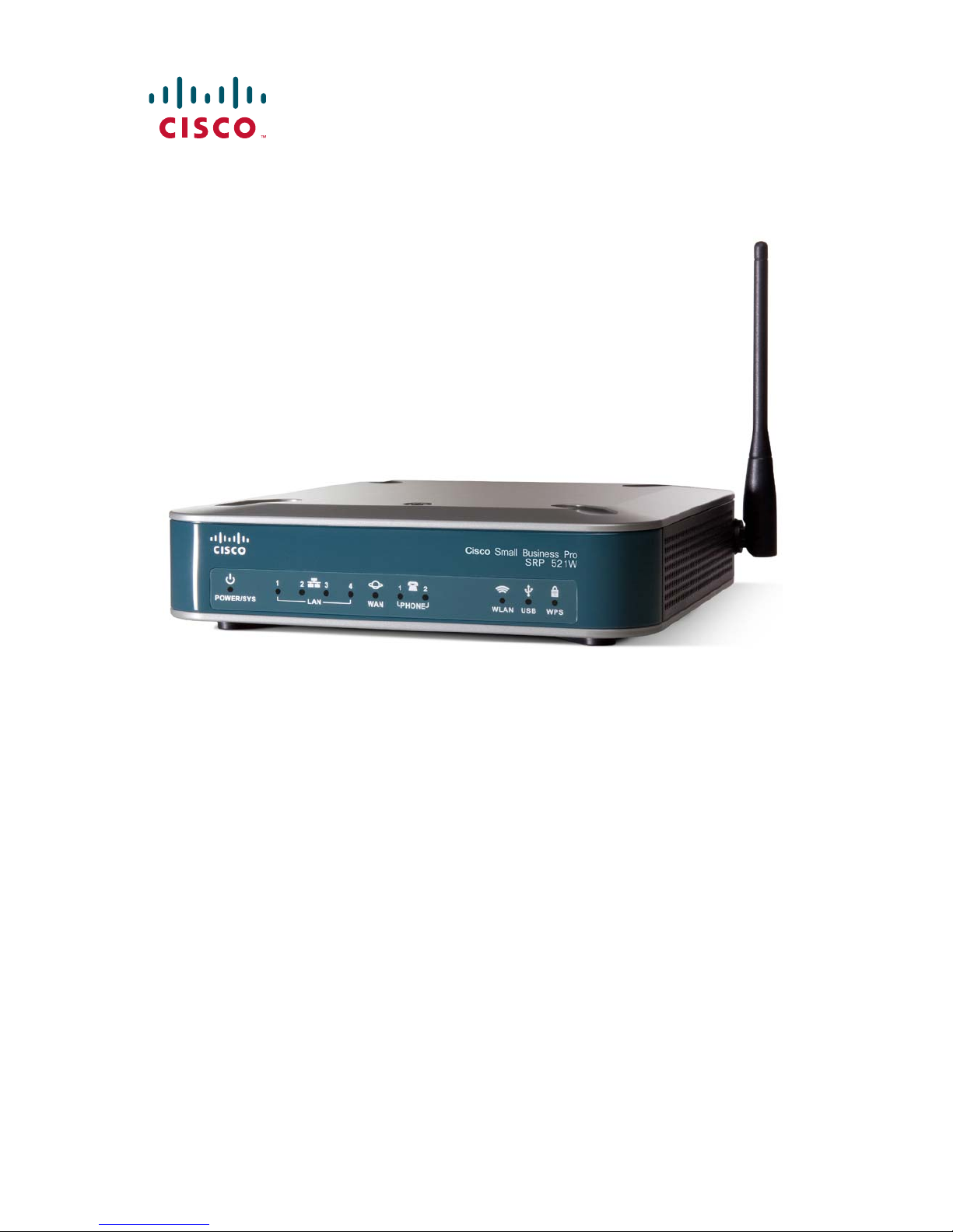
Cisco SRP500 Series Services Ready Platforms
(SRP520 Models)
Package Contents
• Cisco SRP500 Series Services Ready Platform
• RJ-45 Ethernet Cable
• RJ-11 Telephone Cable
• Power Clip and Adapter
• Quick Start Guide
• Product CD
Page 2

Welcome
1
Thank you for choosing Cisco SRP500 Series Services Ready Platforms.
This guide describes how to physically install the SRP and how to use the
Setup Wizard to configure it.
Before You Begin
Before you begin the installation, make sure that you have the following:
For Hardware Installation
• An active Internet connection.
• (Optional) Analog phone line.
• (Optional) Telephone handset, fax machine, or PBX line for connecting
to the voice ports.
• Cables
– RJ-45 Ethernet cables (Category 5 or higher) for connecting
computers, WAN and LAN interfaces, phones, or other devices.
– RJ-11 telephone cable for analog line (FXO) and phone (FXS)
connections.
– ADSL splitter, if required by your Service Provider.
• (Optional) Mobile Broadband USB Modem.
For Software Installation:
• A computer running:
– Microsoft Internet Explorer 7.0 (or later), or Mozilla Firefox 3.6.
– Adobe Flash Player with add-on version 10.0.0 or later (needed to
to configure your SRP).
2 Cisco SRP500 Services Ready Platforms Quick Start Guide (SRP520 Models)
Page 3

Default Settings
2
Use these default settings when configuring your SRP with the Setup
Wizard. See Getting Started with the Configuration, page 11.
Parameter Value
Device IP 192.168.15.1
Username cisco
Password cisco
DHCP Range 192.168.15.100 to 149
To configure advanced features (such as wireless, network, and voice
settings), log in by using the Administrator account.
For more information, see the Cisco SRP500 Series Services Ready
Platforms Administration Guide (SRP520 Models) at:
www.cisco.com/go/srp500.
NOTE If you obtained your SRP from your Service Provider, you might not
have access to the Administrator account. Contact your Service
Provider for more information.
Getting to Know the Cisco SRP500 Series
Services Ready Platforms
This section lists the available model numbers to help you become familiar
with your SRP, and shows the front panel, back panel, side view, and top
the unit.
NOTE To get started with the installation right away, see Installing the
SRP500 Services Ready Platforms, page 8.
Cisco SRP500 Services Ready Platforms Quick Start Guide (SRP520 Models) 3
Page 4
Model Numbers
276377
LANPOWER/SYS
PHONE USB WPSWLANWLAN
Cisco Small Business Pro
SRP 521W
12 2143
LANPOWER/SYS
PHONE
CD Data
DSL
USB WPSWLAN
Cisco Small Business Pro
SRP 526W
12 2143
Model Description
SRP521W Fast Ethernet WAN
2 Phone (FXS) ports, 1 Line (FXO) port, 1 WAN (10/100) port,
4 LAN (10/100) ports, 1 USB 2.0 port, 802.11n, and WiFi Protected
Setup (WPS)
SRP526W ADSL2+ Annex B (ADSL over ISDN)
2 Phone (FXS) ports, 1 Line (FXO) port, 1 DSL port,
4 LAN (10/100) ports, 1 USB 2.0 port, 802.11n, and WiFi Protected
Setup (WPS)
SRP527W ADSL2+ Annex A/M (ADSL over POTS)
2 Phone (FXS) ports, 1 Line (FXO) port, 1 DSL port,
4 LAN (10/100) ports, 1 USB 2.0 port, 802.11n, and WiFi Protected
Setup (WPS)
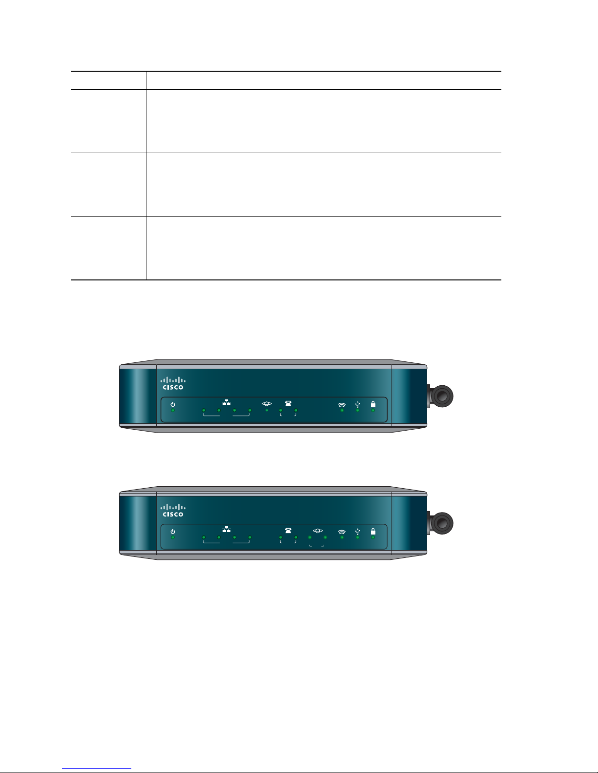
Front Panel
SRP521W Front Panel
SRP526W and SRP527W Front Panel
4 Cisco SRP500 Services Ready Platforms Quick Start Guide (SRP520 Models)
Page 5

Front Panel Lights
The following table describes the lights on the front panel of the SRP.
These lights are used for monitoring system activity.
Lights (Green) Description
POWER/SYS Lights when the SRP has successfully booted and is ready
to use. Flashes when the SRP is booting.
LAN ports (1–4) Lights when a link is established. Flashes when there is
activity on the LAN port.
WAN p or t
(SRP 521W only)
Phone (FXS) ports
(1– 2)
DSL CD Flashes when a DSL service is detected. Lights solid green
DSL Data
(SRP 526W/527W only)
WLAN Lights when the radio is powered on and operational.
USB port
WPS button Lights when WiFi Protected Setup (WPS) is operational.
Lights when a link established. Flashes when there is
activity on the WAN port.
Lights when the port is connected to a phone or fax
machine and the SRP is able to make and receive calls.
Flashes when a call is in progress on the port.
when synchronized.
Flashes when there is DSL activity on the line.
Flashes when there is wireless activity on the WLAN port.
Lights when the connected USB device is operational.
Flashes if there is a device failure or unsupported device.
A slow green flash indicates that the setup is in progress. A
fast green flash indicates a setup error.
Back Panel
The back panel is where you connect the network devices. The ports on
the panel vary depending on the model.
Cisco SRP500 Services Ready Platforms Quick Start Guide (SRP520 Models) 5
Page 6

SRP521W Back Panel
195211
LAN (10/100)LAN/WAN
21 1234
LINE (FXO)DSL PHONE (FXS)
On/Off
Switch
Line
(FXO)
Por t
DSL
Por t
Phone
(FXS)
Por ts
LAN
Por ts
12 V DC
power
Line
(FXO)
Por t
21 1234
LINE (FXO)PHONE (FXS)
WAN
Por t
Phone
(FXS)
Por ts
SRP526W and SRP527W Back Panel
LAN (10/100)WAN (10/100)
LAN
Por ts
On/Off
Switch
12VDC
276375
12 V DC
power
Back Panel Descriptions
Feature Description
DSL port
SRP526/SRP527W only
Phone (FXS) ports (1–2) Connect directly to an analog telephone, fax machine,
Line (FXO) port Connects to a PSTN, which is the analog telephone
6 Cisco SRP500 Services Ready Platforms Quick Start Guide (SRP520 Models)
Connects the SRP to your DSL connection.
or similar device.
If your analog phone requires a separate bell line (as
might be the case in the United Kingdom), you might
need to connect a ring adapter between the SRP and
your phone so that the phone rings when calls are
presented.
service network that a traditional telephone service
uses.
Page 7

WAN (10/100) port
SRP521W only
Connects the SRP to your Wide-Area-Network (WAN).
LAN (10/100) ports (1–4) Connects to a wired computer and other network
devices.
On/Off Switch Powers the SRP on or off.
12 V DC power Connects to the provided power adapter.
Side View
Reset
Button
RESET
Feature Description
USB
Connector
276380
Antenna
276381
Reset button Press and hold for 5 seconds to reset the SRP. Press
USB port Connects to a compatible USB Modem.
Antenna The WiFi antenna.
Cisco SRP500 Services Ready Platforms Quick Start Guide (SRP520 Models) 7
and hold for 10 seconds to reset the SRP to its factory
defaults.
To press the button, insert a paper clip or similar
object into the opening.
CAUTION Resetting the unit will delete all user
settings
.
See Installing a Mobile Broadband USB Modem
(Optional), page 12.
Page 8

Top View
3
Feature Description
276378
WPS Button
WPS Button Use to automatically configure wireless security for devices
that support WiFi Protected Setup (WPS).
To configure WPS, press and hold this button until the WPS
light flashes. Make sure that the device is located near the
SRP during setup.
Installing the SRP500 Services Ready
Platforms
You can install the SRP on a desktop or other flat horizontal surface or
mount it on a wall.
NOTE The SRP has an adjustable WiFi antenna located on the side panel
of the unit.
Placement Tips
Make sure that you install the SRP in a location that meets these
environmental conditions:
•Storage Temperature (sea level) -22° F to 140° F (-30° C to +60° C)
•Operating Temperature (sea level) 32° F to 104° F (0° C to 40° C)
• Relative Humidity (sea level) 5 to 95% RH (non-condensing)
8 Cisco SRP500 Services Ready Platforms Quick Start Guide (SRP520 Models)
Page 9

CAUTION Do not stack or place anything on top of the SRP, or install it on
4
a hot surface.
Desk Placement
To mount the SRP on a desktop, place the device horizontally on a flat
surface so it sits on its four rubber feet.
Wall Mounting
NOTE Position the SRP so that the back panel faces upward to reduce
strain on the cable connections.
STEP 1 Secure two number-six pan-head tapping screws, 3/4-inch (19 mm)
in length, 150 mm apart into a wall for horizontal orientation or
108 mm for vertical orientation, with the space between the
underside of each screw head and the surface of the wall equal to
5/32 inch (4mm).
CAUTION For drywall installation, secure the screws by using two
hollow-wall anchors (1/8 inch with 5/16-inch drill bit, or M3
with 8-mm drill bit). Without proper anchoring, the strain of
the network cable connections could pull the SRP from
the wall.
STEP 2 Locate the mounting screw slots on the bottom of the SRP, and
then hang it on the screws.
Connecting the Equipment
STEP 1 For Ethernet WAN connections, connect one end of the Ethernet
cable to your Internet access device (typically a modem), and
connect the other end of the cable to the WAN port.
For ADSL connections, connect your DSL cable directly to the DSL
port on your SRP526W or SRP527W. Make sure that you use an
ADSL splitter, if required by your Service Provider.
Cisco SRP500 Services Ready Platforms Quick Start Guide (SRP520 Models) 9
Page 10

SRP521W WAN Connection
21 1234
LINE (FXO)PHONE (FXS)
LAN (10/100)WAN (10/100)
12VDC
195790
WAN (10/100) Port
SRP526W / SRP527W ADSL Connection
21 1234
LINE (FXO)DSL PHONE (FXS)
LAN (10/100)LAN/WAN
199989
DSL Port
STEP 2 Connect wired computers and other network devices to the LAN
ports (1–4).
STEP 3 (Optional) Connect an analog telephone, fax machine, or similar
device to the Phone (FXS) ports. Then connect the Line (FXO) port
to the telephone line on your phone jack.
STEP 4 Install the supplied AC power plug or clip (for your area) into the
power adapter.
NOTE Only use the power adapter that was provided with the unit.
STEP 5 Connect the power adapter to the 12 VDC port on your SRP.
21 1234
LINE (FXO)PHONE (FXS)
LAN (10/100)WAN (10/100)
12VDC
195791
10 Cisco SRP500 Services Ready Platforms Quick Start Guide (SRP520 Models)
Page 11

TEP 6 Insert the AC power plug into an electrical outlet.
5
6
S
STEP 7 Orient the antenna to the vertical position.
STEP 8 Press the On/Off switch to the on position.
The POWER/SYS light on the front panel flashes green while the
SRP boots. After booting, the light turns solid green.
The hardware installation is now complete.
Verifying the Hardware Installation
To verify the hardware installation, complete these tasks:
• Check the cable connections.
• Check the lights, as described in Front Panel Lights, page 5. Verify that
the POWER/SYS light is solid green.
If you encounter problems, go to the Cisco Small Business Support
Community website at www.cisco.com/go/smallbizsupport. For technical
documentation and other links, see Where to Go From Here, page 13.
Getting Started with the Configuration
After you install the SRP, configure it by using the Setup Wizard.
Before you get started, verify that your computer meets the software
requirements as specified in Before You Begin, page 2.
STEP 1 Configure your computer to use DHCP for its LAN connection.
Using an Ethernet cable, connect your computer to an available
LAN port (1-4) on the SRP. Your computer will automatically obtain
an IP address in the 192.168.15.x range.
STEP 2 Start a web browser.
In the Address bar, enter the default IP address:
http://192.168.15.1
STEP 3 When the login page appears, enter the username and password.
The default username is cisco.
The default password is cisco.
NOTE Passwords are case sensitive.
STEP 4 Click Log In.
Cisco SRP500 Services Ready Platforms Quick Start Guide (SRP520 Models) 11
Page 12

The browser displays the first page of the Setup Wizard.
7
STEP 5 Follow the on-screen prompts to complete the initial configuration.
The installation is complete.
Installing a Mobile Broadband USB Modem
(Optional)
Optionally, you can connect a Mobile Broadband USB Modem to your SRP.
Before installing it, make sure that your modem is compatible.
To view a current list of compatible modems, see
www.cisco.com/go/srp500, and click Reference Guides.
NOTE Mobile Broadband USB Modems are for data services only.
STEP 1 Make sure your modem is activated with a data service, and verify
that it can be used on your computer.
STEP 2 Connect the modem into the USB port on your SRP.
The modem is fully operational when the USB light turns
solid green.
To check the modem status and modify the settings for the mobile
network, connection recovery, and failover settings, refer to its
product documentation.
For more information, see the Cisco SRP500 Series Services Ready
Platforms Administration Guide (SRP520 Models) at:
www.cisco.com/go/srp500.
12 Cisco SRP500 Services Ready Platforms Quick Start Guide (SRP520 Models)
Page 13

Where to Go From Here
8
Support
Cisco Small Business Support
Community
Online Technical Support and
Documentation (Login required)
Phone Support Contacts www.cisco.com/en/US/support/
Firmware Upgrade (click the
Download Software link)
www.cisco.com/go/smallbizsupport
For information about the SRP, click Small
Business Routers from the Community page.
www.cisco.com/support
tsd_cisco_small_business
_support_center_contacts.html
www.cisco.com/go/srp500
Product Documentation
Cisco SRP500 Series Services
Ready Platforms for Small
Business
www.cisco.com/go/srp500
Cisco Small Business
Cisco Partner Central for Small
Business (Partner Login
Required)
www.cisco.com/web/partners/sell/smb
Cisco Small Business Home www.cisco.com/smb
Marketplace www.cisco.com/go/marketplace
Cisco SRP500 Services Ready Platforms Quick Start Guide (SRP520 Models) 13
Page 14

14 Cisco SRP500 Services Ready Platforms Quick Start Guide (SRP520 Models)
Page 15

Cisco SRP500 Services Ready Platforms Quick Start Guide (SRP520 Models) 15
Page 16

Americas Headquarters
Cisco Systems, Inc.
170 West Tasman Drive
San Jose, CA 95134-1706
USA
www.cisco.com
Small Business Support US: 1-866-606-1866 (Toll Free, 24/7)
Small Business Support, Global: www.cisco.com/go/sbsc
78-19239-02
Cisco and the Cisco Logo are trademarks of Cisco Systems, Inc. and/or its affiliates in the U.S.
and other countries. A listing of Cisco's trademarks can be found at www.cisco.com/go/
trademarks. Third party trademarks mentioned are the property of their respective owners.
The use of the word partner does not imply a partnership relationship between Cisco and any
other company. (1005R)
© 2010 Cisco Systems, Inc. All rights reserved.
 Loading...