

Page 1
ADMINISTRATION
390487
GUIDE
Cisco SPA232D Mobility Enhanced Phone Adapter
Page 2

Contents
Chapter 1: Getting Started 5
Feature Overview 5
Understanding Voice Service Operations 6
ATA Voice Features 6
Before You Begin 12
Product Features 12
Connecting the Equipment 15
Configuration and Management of the ATA 16
Registering a Cisco SPA302D Handset 17
Additional Information 18
Using the IVR for Administration 18
Mounting the ATA 22
Elements of the User Interface 24
Chapter 2: Quick Setup for Voice over IP Service 26
Chapter 3: Configuring the Network 29
Basic Setup 29
Network Service 29
Internet Settings 31
Network Settings for the LAN and DHCP Server 34
Time Settings 37
Advanced Settings 39
Port Setting 39
MAC Address Clone 40
VPN Passthrough 41
VLAN 42
CDP & LLDP 43
Application 44
Quality of Service (QoS) 44
Port Forwarding 45
Cisco SPA232D Administrator Guide 1
Page 3

Manually Adding Port Forwarding 46
DMZ 48
Contents
Chapter 4: Configuring the Voice Settings 49
Information 50
System 60
SIP 64
Provisioning 74
Regional 80
Line 1 Settings (PHONE Port) 100
Configuration Tables 117
PSTN (LINE Port) 125
User 1 147
PSTN User 152
DECT Line 1 - DECT Line 10 154
DECT User 174
SSL/TLS Certificate 177
Server Certification 177
Client Certification 178
Chapter 5: Administration Settings 179
Management 179
Web Access Management 180
TR-069 182
SNMP 184
User List (Password Management) 186
Bonjour 187
Reset Button 187
Logging 187
Log Module 188
Log Setting 190
Cisco SPA232D Administrator Guide 2
Page 4

Log Viewer 192
Contents
Diagnostics 193
Ping Test 193
Traceroute Test 193
Factory Defaults 194
Firmware Upgrade 194
Configuration Management 195
Backup Configuration 195
Restore Configuration 195
Reboot 196
Chapter 6: Viewing the Status and Statistics 197
System Information 197
Interface Information 198
Internet Status 199
Port Statistics 200
Memory Information 201
DHCP Server Information 202
Optimizing Fax Completion Rates 212
VoIP-to-PSTN and PSTN-to-VoIP Calling 215
How VoIP-To-PSTN Calls Work 215
How PSTN-To-VoIP Calls Work 217
Terminating Gateway Calls 218
VoIP Outbound Call Routing 218
Configuring VoIP Failover to PSTN 220
Sharing One VoIP Account Between the PHONE and LINE Ports 220
PSTN Call to Ring Line 1 221
Symmetric RTP 221
Call Progress Tones 221
Call Scenarios 222
PSTN to VoIP Call with and Without Ring-Thru 222
Cisco SPA232D Administrator Guide 3
Page 5

VoIP to PSTN Call With and Without Authentication 223
Call Forwarding to PSTN Gateway 224
Contents
Configuring Dial Plans 225
Digit Sequences 226
Acceptance and Transmission of the Dialed Digits 230
Dial Plan Timer (Off-Hook Timer) 231
Interdigit Long Timer (Incomplete Entry Timer) 232
Interdigit Short Timer (Complete Entry Timer) 233
Resetting the Control Timers 234
Cisco SPA232D Administrator Guide 4
Page 6

Getting Started
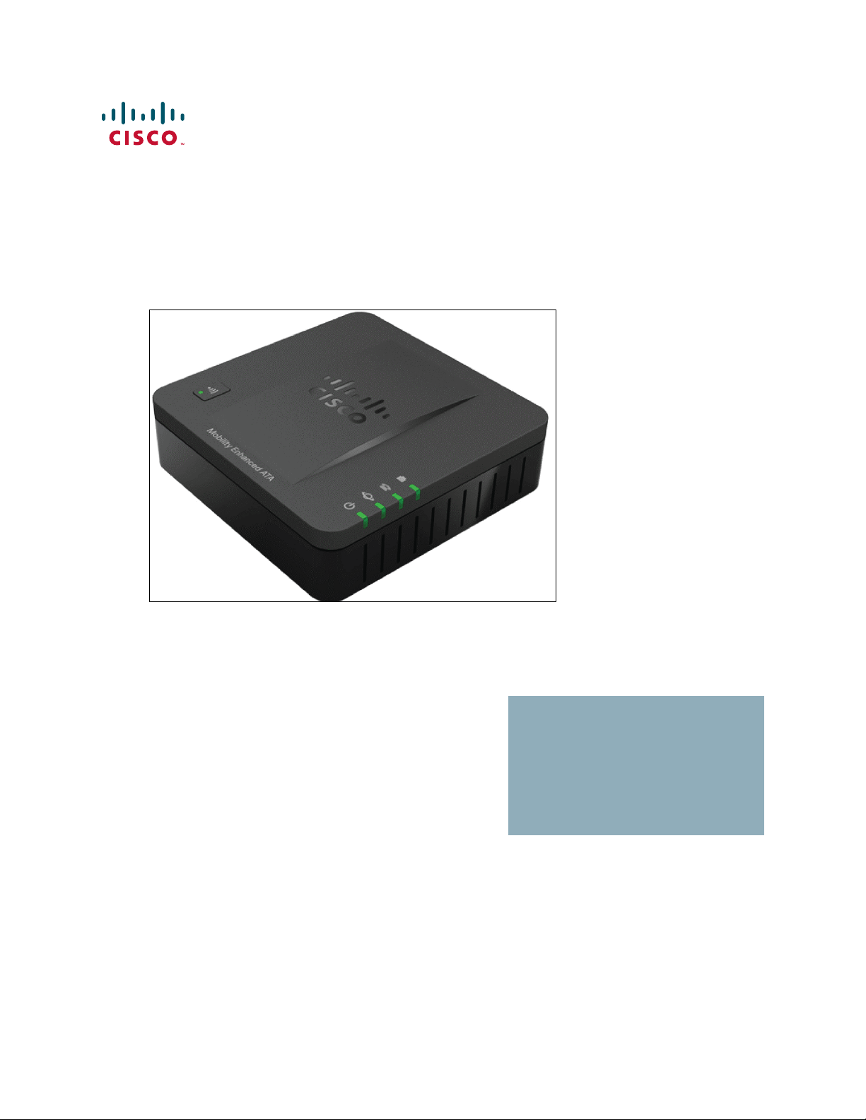
Thank you for choosing the Cisco SPA232D Mobility Enhanced Analog Telephone
Adapter (ATA). This chapter provides more information about the features of the
product and provides instructions about connecting the equipment and getting
started in the web-based configuration utility.
Feature Overview
With the Cisco SPA232D Mobility Enhanced ATA, you can provide your analog
phone and Cisco SPA302D cordless handsets with access to analog and Internet
phone services through a standard RJ-11 phone port and a built-in DECT base
station. The ATA supports up to five Cisco SPA302D handsets. The ATA connects
to the Internet through a broadband (DSL or cable) modem or router. The ATA can
be used with an on-site call-control system or an Internet-based call-control
system.
1
The ATA is an intelligent low-density Voice over IP (VoIP) gateway that enables
carrier-class residential and business IP Telephony services delivered over
broadband or high-speed Internet connections. An ATA maintains the state of each
call it terminates and reacts appropriately to user input events (such as on/off hook
or hook flash). The ATAs use the Session Initiation Protocol (SIP) open standard so
there is little or no involvement by a “middle-man” server or media gateway
controller. SIP allows inter-operation with all ITSPs that support SIP.
The system supports four simultaneous calls, including “active” calls and “on-hold”
calls. A phone or DECT handset can handle one on-hold call and one active call
simultaneously.
Cisco SPA232D Administration Guide 5
Page 7
Getting Started
IP
Analogue
Phone
(FXS port)
or
or
FXS/DECT
LAN
PC
FXO
WAN
Active PSTN L
Cisco SPA232D
Internet Service Provider
Internet (ADSL/Cable
Modem)
Cordless
Phone
(DECT)
Fax Machine
(FXS port)
Feature Overview
1
Understanding Voice Service Operations
The ATA allows calls to be made by using SIP-based Voice-over-IP (VoIP) services
and traditional telephone Public Switched Telephone Network (PSTN) services.
Calls can be placed and received by using an analog phone or fax machine and
Cisco SPA302D handsets.
Cisco SPA232D Administration Guide 6
The ATA maintains the state of each call and makes the proper reaction to user
input events (such as on/off hook or hook flash). Because the ATA uses the Session
Initiation Protocol (SIP), it is compatible with most Internet Telephony Service
Provider (ITSP) offerings.
ATA Voic e Fe atures
The ATA can be custom provisioned within a wide range of configuration
parameters. The following sections describe the factors that contribute to voice
quality:
• Supported Codecs
• SIP Proxy Redundancy
• Other ATA Voice Features
Page 8

Getting Started
Feature Overview
1
Supported Codecs
The ATA supports the codecs listed below. You can use the default settings or
configure the codec settings in the Audio Configuration section of these pages:
Line 1 Settings (PHONE Port), PSTN (LINE Port), and DECT Line 1 - DECT Line
10.
Codec Description
G.711 (A-law and mu-law) Very low complexity codecs that support
uncompressed 64 kbps digitized voice
transmissions at one through ten 5 ms voice frames
per packet. These codecs provide the highest
narrow-band voice quality and uses the most
bandwidth of any of the available codecs.
G.726-32 Low complexity codec that supports compressed
32 kbps digitized voice transmission at one through
ten 10 ms voice frames per packet. This codec
provides high voice quality.
G.729a ITU G.729 voice coding algorithm used to
compress digitized speech. G.729a is a reduced
complexity version of G.729 requiring about half
the processing power of G.729. The G.729 and
G.729a bit streams are compatible and
interoperable, but not identical.
Cisco SPA232D Administration Guide 7
Page 9

Getting Started
Feature Overview
1
SIP Proxy Redundancy
In typical commercial IP Telephony deployments, all calls are established through
a SIP proxy server. A typical SIP proxy server can handle thousands of
subscribers. It is important that a backup server be available so that an active
server can be temporarily switched out for maintenance. The ATA supports the
use of backup SIP proxy servers (through DNS SRV) so that service disruption is
minimized.
An easy way to support proxy redundancy is to configure your DNS server with a
list of SIP proxy addresses. The ATA can be instructed to contact a SIP proxy
server in a domain named in the SIP message. The ATA consults the DNS server to
get a list of hosts in the given domain that provide SIP services. If an entry exists,
the DNS server returns an SRV record that contains a list of SIP proxy servers for
the domain, with their host names, priority, listening ports, and so on. The ATA tries
to contact the list of hosts in the order of their stated priority.
If the ATA is currently using a lower priority proxy server, it periodically probes the
higher priority proxy to see whether it is online, and switches back to the higher
priority proxy when possible. You can use the default settings or configure the
Proxy Redundancy Method in the Proxy and Registration section of the Line 1
Settings (PHONE Port) page and the DECT Line 1 - DECT Line 10 pages.
Other ATA Voice Features
• Silence Suppression and Comfort Noise Generation
Voice Activity Detection (VAD) with Silence Suppression is a means of
increasing the number of calls supported by the network by reducing the
average bandwidth required for a single call. VAD distinguishes between
speech and non-speech signals, and Silence Suppression removes the
natural silences that occur in a conversation. Therefore the IP bandwidth is
used only to transmit speech. Comfort Noise Generation provides
artificially-generated background white noise (sounds) to reassure callers
that their calls are still connected during the silent periods. You can enable
this feature in the Audio Configuration section of these pages: Line 1
Settings (PHONE Port), PSTN (LINE Port), and DECT Line 1 - DECT Line
10.
• Modem and Fax Pass-Through
- Modem pass-through mode can be triggered by predialing the Vertical
Service Activation Code for the Modem Line Toggle Code. You can
configure this setting in the Vertical Service Activation Codes section
of the Regional page.
Cisco SPA232D Administration Guide 8
Page 10

Getting Started
Feature Overview
1
- FAX pass-through mode is triggered by the detection of a CED/CNG
tone or an NSE event.
- Echo canceller is automatically disabled for Modem passthrough mode.
- Echo canceller is disabled for FAX pass-through if the parameter FAX
Disable ECAN (Line 1 or 2 tab) is set to “yes” for that line (in that case
FAX pass-through is the same as Modem pass-through)
- Call waiting and silence suppression are automatically disabled for both
FAX and Modem pass-through. In addition, out-of-band DTMF
transmission is disabled during modem or fax passthrough.
NOTE For more information, please refer to Audio Configuration, page 113 and
Configuration Tables, page 117.
• Adaptive Jitter Buffer
The ATA can buffer incoming voice packets to minimize the impact of
variable network delays. This process is known as jitter buffering. The size
of the jitter buffer adjusts to changing network conditions. The ATA has a
Network Jitter Level control setting for each line of service. The jitter level
determines how aggressively the ATA tries to shrink the jitter buffer over
time to achieve a lower overall delay. If the jitter level is higher, it shrinks
more gradually. If jitter level is lower, it shrinks more quickly. You can use the
default settings or configure this feature in the Network Settings section of
these pages: Line 1 Settings (PHONE Port), PSTN (LINE Port), and DECT
Line 1 - DECT Line 10.
• Adjustable Audio Frames Per Packet
This feature allows the user to set the number of audio frames contained in
one RTP packet. Packets can be adjusted to contain from 1–10 audio
frames. Increasing the number of packets decreases the bandwidth utilized,
but it also increases delay and may affect voice quality. You can configure
this setting in the RTP Parameters section of the SIP page.
• DTMF Relay
The ATA may relay DTMF digits as out-of-band events to preserve the
fidelity of the digits. This can enhance the reliability of DTMF transmission
required by many IVR applications such as dial-up banking and airline
information. You can configure this setting in the RTP Parameters section of
the SIP page.
• Call Progress Tones
The ATA has configurable call progress tones. Call progress tones are
generated locally on the ATA so that an end user is advised of status (such
as ringback) Parameters for each type of tone (for instance a dial tone
Cisco SPA232D Administration Guide 9
Page 11

Getting Started
Feature Overview
1
played back to an end user) may include frequency and amplitude of each
component, and cadence information. You can keep the default settings or
configure these tones in the Call Progress Tones section of the Regional
page.
• Call Progress Tone Pass Through
This feature allows the user to hear the call progress tones (such as ringing)
that are generated from the far-end network.
• Echo Cancellation
Impedance mismatch between the telephone and the IP Telephony
gateway phone port can lead to near-end echo. The ATA has a near-end
echo canceller that compensates for impedance mismatch. The ATA also
implements an echo suppressor with Comfort Noise Generator (CNG) so
that any residual echo is not noticeable. This feature is enabled by default.
You can configure this setting in the Audio Configuration of these pages:
Line 1 Settings (PHONE Port), PSTN (LINE Port), and DECT Line 1 DECT Line 10.
• Hook Flash Events
The ATA can signal hook flash events to the proxy during a connected call.
This feature can be used to provide advanced mid-call services with thirdparty-call control.
- Depending on the features that the service provider offers using third-
party-call-control, you may need to disable Call Waiting Service, Three
Way Conference Service, or Three Way Call Service to correctly signal a
hook flash event to the softswitch. You can configure these settings in
the Supplementary Service Subscription section of the Line 1 Settings
(PHONE Port) page and the DECT Line 1 - DECT Line 10 pages.
- You can configure the length of time allowed for detection of a hook flash
by adjusting the Hook Flash Timer parameter in the Control Timer
Values section of the SIP page.
• Configurable Dial Plan with Interdigit Timers
The ATA has three configurable interdigit timers: an initial timeout signaling
that a phone is taken off hook, a long timeout signaling the end of a dialed
string, and a short timeout, signaling that more digits are expected. For more
information, see Configuring Dial Plans, page 225.
• Polarity Control
The ATA allows the polarity to be set when a call is connected and when a
call is disconnected. This feature is required to support some pay phone
system and answering machines. You can configure these settings in the
Cisco SPA232D Administration Guide 10
Page 12

Getting Started
Feature Overview
1
FXS Port Polarity Configuration section of the Line1 Settings (PHONE
Port) page.
• Calling Party Control
Calling Party Control (CPC) signals to the called party equipment that the
calling party has hung up during a connected call by momentarily removing
the voltage between the tip and the ring. This feature is useful for
auto-answer equipment. You can configure these settings in the Control
Timer Values section of the Regional page.
• Event Logging
You can enable logging and select the relative priority of events to be
logged. The information can be sent to a Syslog Server. You can configure
the syslog and debug settings in the Miscellaneous Settings section of the
System page.
• Encryption of SIP messages using SIP over TLS
You can enable SIP over Transport Layer Security (TLS) to encrypt the SIP
messages between the service provider and the your business. SIP over
TLS relies on the widely-deployed and standardized TLS protocol to
encrypt the signaling messages. You can configure the SIP Transport
parameter in the SIP Settings section of these pages: Line 1 Settings
(PHONE Port), PSTN (LINE Port), and DECT Line 1 - DECT Line 10.
• Secure Calling using SRTP
Voice packets are encrypted by using Secure Real-Time Transport Protocol
(SRTP). This function is implemented on a standards basis (RFC4568).
Secure call service (Secure Call Serv) is enabled by default in the
Supplementary Service Subscription section of these pages: Line 1
Settings (PHONE Port) and DECT Line 1 - DECT Line 10. When this
service is enabled, users can activate secure calling by pressing the star (*)
key before dialing a phone number. Alternatively, you can enable the Secure
Call Setting to encrypt all calls from a user’s phone or a DECT line. See the
Supplementary Service Settings section of the User 1 page and the DECT
Line 1 - DECT Line 10 page.
Cisco SPA232D Administration Guide 11
Page 13

Getting Started
Before You Begin
Before You Begin
Before you begin the installation, make sure that you have the following equipment
and services:
1
• An active Internet account and Voice over IP account
• Ethernet cable to connect to your broadband network device
• Phone to connect to your ATA
• Phone cable to connect your phone
• Optional: Uninterruptible Power Supply (UPS) to provide backup power
• Optional: Cisco SPA302D Mobility Enhanced Cordless Handsets
Product Features
Top Panel
Feature Description
Registration
INTERNET
Page/
LINE
PHONE
Steady green—One or more handsets is
registered.
Fast flashing green—The base is in registration
mode. To activate registration mode, press the
button for at least 7 seconds.
Slow flashing green—The base is in paging mode
or a handset is off hook. To activate paging mode to
locate a handset, press the button for a few
seconds; handsets ring.
Off—No handset is registered to the base.
Steady green—The line is off hook and connected
to the local telephone system.
Slow flashing green—The line is off hook.
Off—The por t is not read y.
Steady green—The device is on hook and
registered to a SIP proxy.
Slow flashing green—The device is off hook.
Off—The por t is not read y.
Flashing green—Transmitting or receiving data
through the WAN port.
Off—No link.
Cisco SPA232D Administration Guide 12
Page 14
Getting Started
Product Features
Feature Description
Steady green—The system is ready.
Slow flashing green—Acquiring an IP address, if
applicable. (DHCP is used by default.)
SYSTEM
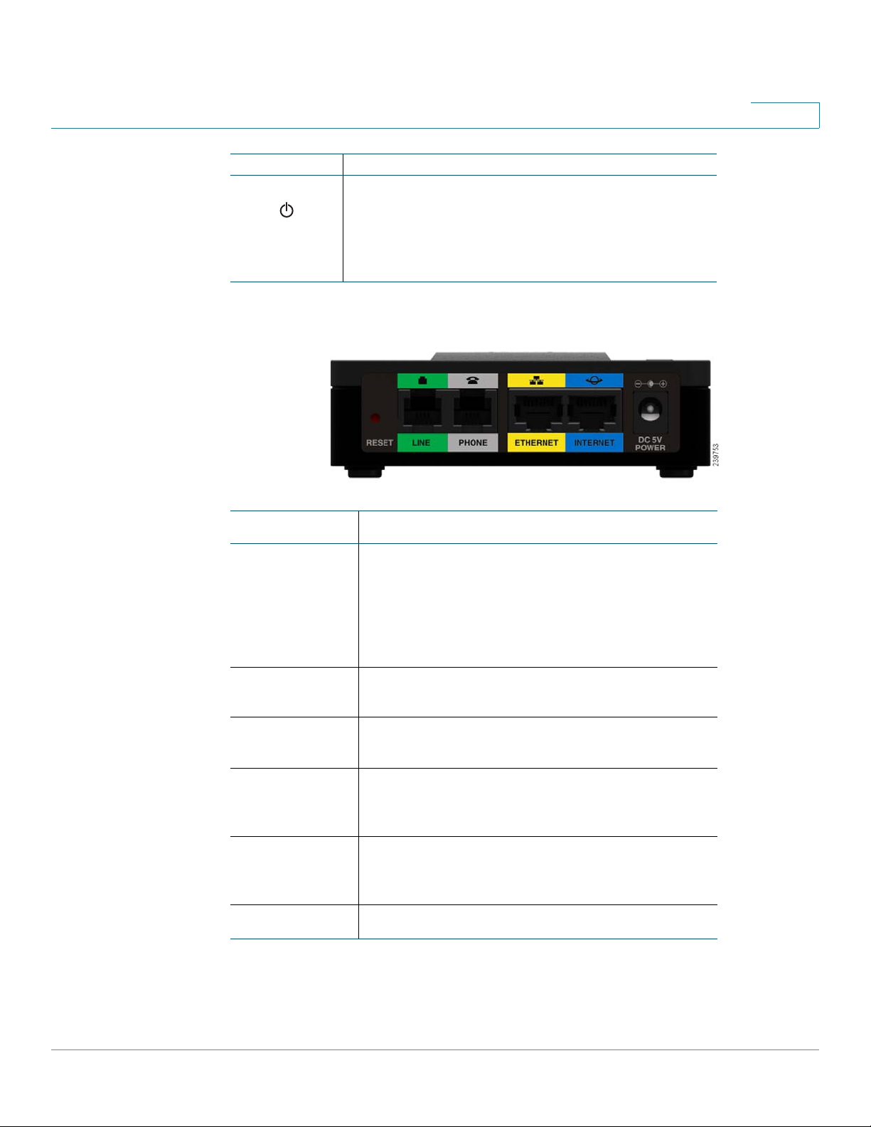
Back Panel
Fast flashing green—Upgrading the firmware.
Off—There is no power or the system cannot boot
up.
1
Feature Description
RESET Performs two functions:
Restart the ATA: Press quickly (less than a second)
with a paperclip or similar object.
Restore the factory default settings: Press and
hold for 5 to 6 seconds.
LINE (Green) Connects to an analog phone line, using an RJ-
11 phone cable.
PHONE (Gray)
ETHERNET
(Yellow)
INTERNET
(Blue)
POWER
Connects to an analog phone, using an RJ-11 phone
cable.
Connects to a device on your local area network
(LAN), such as a computer by using an Ethernet
cable.
Connects to a broadband network device (DSL or
cable modem) or a network router by using an
Ethernet cable.
Connects to a power by using the provided adapter.
Cisco SPA232D Administration Guide 13
Page 15

Getting Started
Product Features
Default Settings
Parameter Default Value
Administrator Username admin
Administrator Password admin
User Username cisco
User Password cisco
Internet Connection Type Automatic Configuration - DHCP
LAN IP Address
(Also the address for the webbased configuration utility.)
DHCP Range
(DHCP server enabled by
default.)
Netmask 255.255.255.0
PIN for handset registration, IP
settings, and SIP settings
192.168.15.1
192.168.15.100-149
Blank
1
Cisco SPA232D Administration Guide 14
Page 16
Getting Started
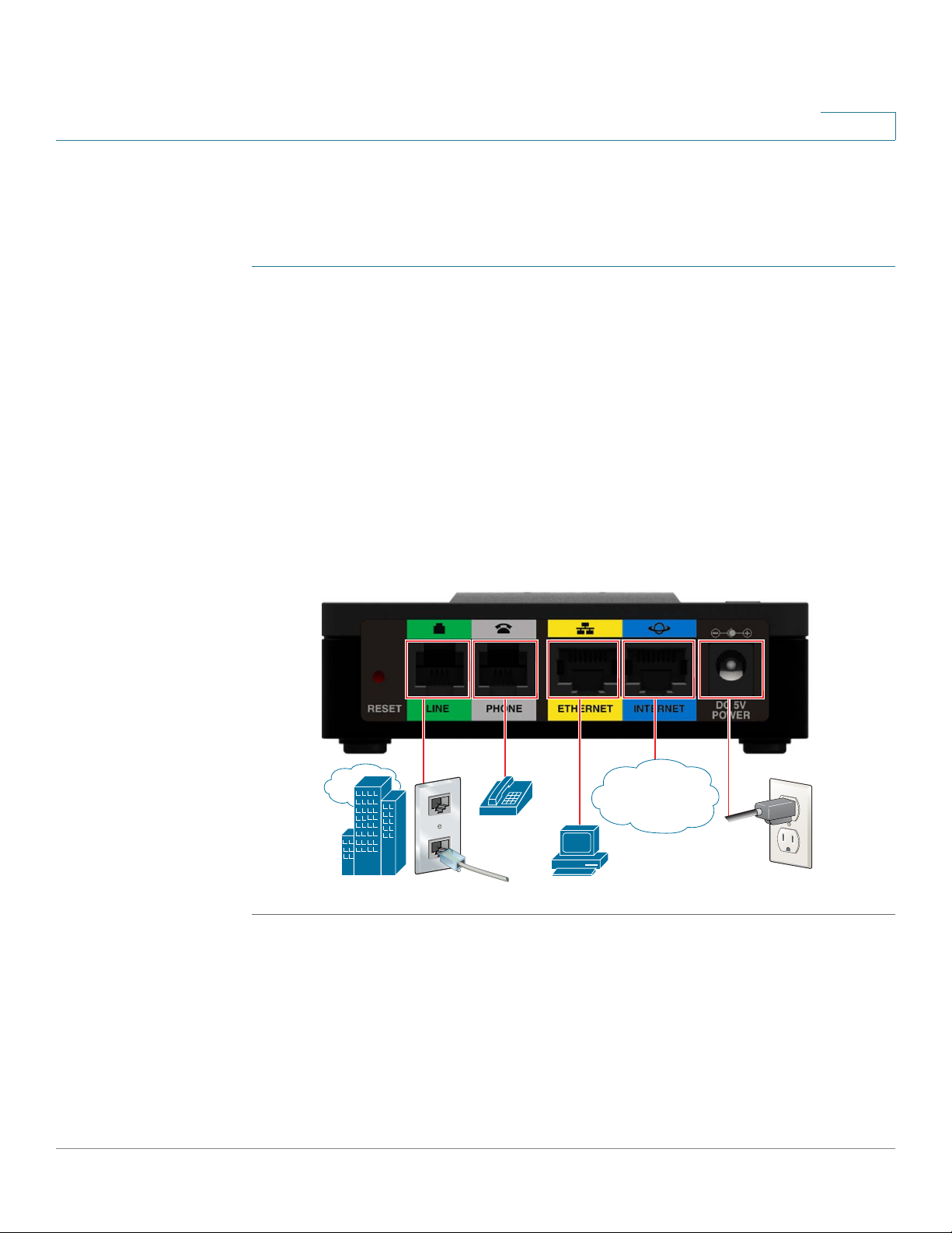
Connecting the Equipment
Connecting the Equipment
NOTE For wall-mounting instructions, see Additional Information, page 18.
STEP 1 Connect the provided Ethernet cable to the INTERNET (Blue) port. Connect the
other end of the cable directly to your broadband network device.
STEP 2 Connect the provided phone cable to the PHONE1 (Gray) port. Connect the other
end of the cable to your analog phone or fax machine.
STEP 3 Optionally, connect an Ethernet network cable to the ETHERNET (Yellow) port of
the ATA. Connect the other end of the cable to a device on your network, such as a
computer.
STEP 4 Connect an analog phone line to the LINE (Green) port to connect the ATA to your
local telephone system.
1
STEP 5 Connect the provided power adapter to the POWER port. The unit powers on.
239756
WAN
Cisco SPA232D Administration Guide 15
Page 17

Getting Started
Configuration and Management of the ATA
Configuration and Management of the ATA
You can use the web-based configuration utility to set up your ATA. You also can
use the built-in Interactive Voice Response (IVR) system. (See Using the IVR for
Administration, page18.)
STEP 1 Connect the provided Ethernet network cable to the ETHERNET (Yellow) port of
the ATA. Connect the other end of the cable to the Ethernet port of your PC.
STEP 2 Power on your computer.
NOTE: Make sure your computer’s Ethernet adapter is set to obtain an IP address
automatically (DHCP). For more information, refer to the Help for your operating
system.
STEP 3 Start a web browser on your computer.
1
STEP 4 In the Address bar, enter: 192.168.15.1
Note: 192.168.15.1 is the default local IP address of the ATA.
STEP 5 To log in for the first time, enter the default username, admin, and the default
password, admin. The password is case sensitive.
NOTE: A user account allows access to limited settings and status pages. To log in
as a user, enter cisco as the username and the password.
STEP 6 Use the Quick Setup page as needed to register your VoIP accounts in the fields
for Line 1 and DECT Line1.
Your VoIP service may require only a few basic parameters to successfully
register the Cisco SPA232D. The Quick Setup page offers a shortcut to enter the
basic parameters. For a more comprehensive listing of parameters, choose the
Voice menu, and then use the links in the navigation tree.
• Enter Proxy: Enter the domain name or URL of the service provider’s proxy
server.
• Display Name: Enter the name of the business. This name typically is used
for the Caller ID.
• User ID: Enter the user ID for your Internet account with this service provider.
• Password: Enter the password for your Internet account.
• Dial Plan (Line 1 only): Keep the default settings (recommended). Detailed
information about the dial plan settings is available in the online Help and the
administration guide.
Cisco SPA232D Administration Guide 16
Page 18

Getting Started
Registering a Cisco SPA302D Handset
Note: The Cisco SPA232D assigns DECT Line1 as the default line for outgoing
calls from Cisco SPA302D handsets. If needed, you can configure additional VoIP
accounts as separate “DECT Lines.” To do so, choose the Voice menu, and then
use the DECT Line 1~10 links in the navigation tree. Use the check boxes on the
Quick Setup page to associate the DECT Line(s) to each handset.
STEP 7 Click Submit to save your settings.
STEP 8 If you wish to change the PIN for handset registration, open the Voice > System
page, and then enter up to four digits in the Handset (HS) Pairing Password field.
Click Submit to save your settings.
Registering a Cisco SPA302D Handset
You can register Cisco SPA302D handsets to the integrated DECT base station.
These handsets can be purchased separately.
1
STEP 1 On the Cisco SPA302D handset, press the center Select button on the 4-way
navigation keypad.
STEP 2 Select Register.
STEP 3 Using the navigation arrows, scroll to the Settings icon and press the center
navigation button to select it.
STEP 4 Select Handset Registration.
STEP 5 On the Cisco SPA232D, press the Page/Registration button and hold it down for
at least seven seconds until the green status light flashes quickly.
TIP: If you press the button for fewer than seven seconds, the green status light
flashes slowly, indicating the unit is in “paging” mode and is not in registration
mode. Registration will not work if the unit is in paging mode.
STEP 6 The default PIN is blank, so do not enter a PIN. Press the left softkey to confirm that
you want to register the handset. The “registering” message appears.
STEP 7 To verify that the handset registered to the base station, confirm that the wireless
status icon is solid and that the handset ID, such as DECT1 or DECT 2, appears
near the top right corner of the display screen.
Cisco SPA232D Administration Guide 17
Page 19

Getting Started
Additional Information
Additional Information
Using the IVR for Administration
An IVR system is available to help you to configure and manage your ATA. You can
use the telephone keypad to select options and to make your entries.
To access the IVR menu:
STEP 1 Connect an analog phone to the PHONE port of the ATA.
STEP 2 Press the star key four times: ****
STEP 3 After the greeting plays, press the keys on the phone keypad to select your
options.
1
STEP 4 Enter the code for the desired action. See the IVR Actions table for details.
TIPS:
• Enter the numbers slowly, listening for the audio confirmation before
entering the next number.
• After you select an option, press the # (pound) key.
• To exit the menu, hang up the telephone or enter 3948# to exit.
• After entering a value, such as an IP address, press the # (pound) key to
indicate that you have finished your selection. To save the new setting,
press 1. To review the new setting, press 2. To re-enter the new setting,
press 3. To cancel your entry and return to the main menu, press * (star).
• While entering a value, you can cancel the changes by pressing the * (star)
key twice within half a second. Be sure to press the key quickly, or the * will
be treated as a decimal point entry.
• If the menu is inactive for more than one minute, the ATA times out. You will
need to re-enter the menu by pressing the star key four times: ****. Your
settings take effect after you hang up the telephone or exit the IVR. The ATA
may reboot at this time.
Cisco SPA232D Administration Guide 18
Page 20

Getting Started
Additional Information
1
• To enter the decimal points in an IP address, press the * (star) key. For
example, to enter the IP address 191.168.1.105, perform the following tasks:
–Press these keys: 191*168*1*105.
–Press the # (pound) key to indicate that you have finished entering the
IP address.
–Press 1 to save the IP address or press the * (star) key to cancel your
entry and return to the main menu.
IVR Actions
IVR Action Menu
Option
Enter IVR Menu ****
Check Internet
Connection Type
Set Internet Connection
Type
Check Internet IP
Address (WAN port)
Set Static IP Address
(WAN)
Check Network Mask 120
100
101 DHCP: 0
110
111 Enter the IP address by
Choices and Instructions
Static IP: 1
PPPoE: Press 2
using numbers on the
telephone key pad. Use the
* (star) key when entering a
decimal point.
Note: This option is
available only after you
choose Static IP as the
Internet Connection Type,
through option 101.
Cisco SPA232D Administration Guide 19
Page 21

Getting Started
Additional Information
1
IVR Action Menu
Option
Set Network Mask 121 To enter the value, press
Check Gateway IP
Address
Set Gateway IP Address 131 To enter the value, press
Check MAC Address 140
Check Firmware Version 150
Check Primary DNS
Server Setting
Set Primary DNS Server 161 To enter the value, press
130
160
Choices and Instructions
numbers on the telephone
key pad. Press the * (star)
key to enter a decimal
point.
Note: This option is
available only after you
choose Static IP as the
Internet Connection Type,
through option 101.
numbers on the telephone
key pad. Press the * (star)
key to enter a decimal
point.
Note: This option is
available only after you
choose Static IP as the
Internet Connection Type,
through option 101.
numbers on the telephone
key pad. Press the * (star)
key to enter a decimal
point.
Note: This option is
available only after you
choose Static IP as the
Internet Connection Type,
through option 101.
Check Internet web
server port
Cisco SPA232D Administration Guide 20
170
Page 22

Getting Started
Additional Information
1
IVR Action Menu
Option
SPA122 only: Check LAN
IP address (Ethernet port)
Announce Line 1 SIP
Transport
Set Line 1 SIP Transport 1911 0: UDP
Check Line 2 SIP
Transport
Set Line 2 SIP Transport 1921 0: UDP
Exit IVR 3948
Allow or prevent WAN
access to the
administration web
server
The system will allow
WAN access only if the
default admin username
and password have been
changed in the
Configuration Utility.
Factory Reset of Unit
WARNING: All nondefault settings will be
lost. This includes
network and service
provider data.
Reboot of Voice System 732668
210
1910
1920
7932 1: Enable
73738
“RESET”
“REBOOT
”
Choices and Instructions
1: TCP
2: TLS
1: TCP
2: TLS
0: Disable
When prompted, press 1 to
confirm, or press * (star) to
cancel. After you hear
“Option successful,” hang
up the phone. The ATA
reboots.
After you hear “Option
successful,” hang up the
phone. The ATA reboots.
Cisco SPA232D Administration Guide 21
Page 23
Getting Started
!
15,8 mm
Additional Information
CAUTION To prevent the ATA from overheating, do not operate it in an area that exceeds an
WARNING Do not place anything on top of the ATA; excessive weight could damage it.
1
Mounting the ATA
You can place the ATA on a desktop or mount it on a wall.
ambient temperature of 104°F (40°C).
Desktop Placement
Place the ATA on a flat surface near an electrical outlet.
Wall Mounting
The ATA has two wall-mount slots on the bottom panel. To mount the ATA on a wall,
you need mounting hardware (not included). Suggested hardware is illustrated
(not true to scale).
Recommended hardware (not included): Two number-six pan-head tapping
screws, 5/8-in. length, with anchors for sheet rock installation.
WARNING Insecure mounting might damage the ATA or cause injury. Cisco is not responsible
for damages incurred by insecure wall-mounting.
Cisco SPA232D Administration Guide 22
Page 24

Getting Started
Additional Information
STEP 1 Determine where you want to mount the unit. Verify that the surface is smooth, flat,
STEP 2 Drill two pilot holes into the surface 58 mm apart (about 2.28 in.). Make sure that
STEP 3 Insert a screw into each hole, leaving a gap of 5 mm (0.1968 in.) between the
STEP 4 Place the unit wall-mount slots over the screws and slide the unit down until the
1
To mount the unit to the wall:
dry, and sturdy.
the holes are at the same height above the floor so that the unit is level and secure
in either of its two safety-certified orientations.
underside of each screw head and the surface of the wall.
screws fit snugly into the wall-mount slots.
Cisco SPA232D Administration Guide 23
Page 25
Getting Started
1
2
3
Elements of the User Interface
Elements of the User Interface
Before you use your ATA, become familiar with the following features of the user
interface.
Screen Elements
1
Component Description
1. Menu Bar
(top)
2. Navigation
Tre e
(left panel)
3. Configuration
Page
(main area)
Cisco SPA232D Administration Guide 24
Provides access to the modules of the
configuration utility. Click a menu to view the
options in the navigation tree.
Provides access to the configuration pages
within the selected module. Click a category
heading to view the list of features. Click a link
to open the configuration page.
Settings for the selected feature.
Page 26

Getting Started
Elements of the User Interface
1
Configuration Utility Icons
Many configuration pages provide the following icons for common tasks.
Icon Description
Edit Icon The Edit icon lets you edit an existing item from a list.
After making your changes, click the Submit button to
save your changes.
Add Item Icon The Add Item icon lets you add an item to a list. After
you have created a new item, click the Submit button to
save the new item.
Delete Item Icon The Delete Item icon lets you delete an item from a list.
After you have deleted an item, click the Submit button
to save your changes.
Saving the Settings
Your settings on a configuration page are not saved until you click the Submit
button. When you navigate to another page, any unsaved settings are abandoned.
Changes cannot be saved while calls are in progress. Try again when the phones
are idle.
To clear the settings without saving them, you can click the Cancel button.
Help
To view information about the configuration pages, click the Help link near the top
right corner of the configuration utility. You can then use the table of contents to
find topics of interest.
Logout
To exit the configuration utility, click the Logout link near the top right corner of the
window. The Login page appears. You can close the browser window.
Cisco SPA232D Administration Guide 25
Page 27

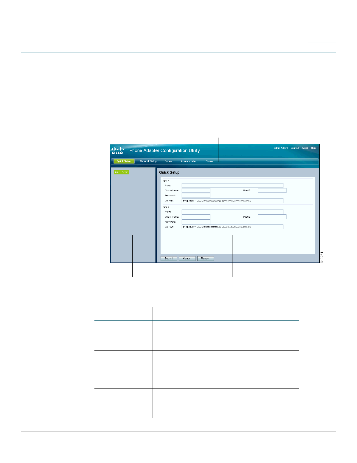
Quick Setup for Voice over IP Service
The Quick Setup page is displayed automatically when you first log on ATA. You
can use this page to quickly configure connectivity to your provider’s Voice over IP
network for your analog phone and Cisco SPA302D handsets.
NOTE Connecting to your service provider’s network requires Internet connectivity. With
the default network settings, your ATA should have Internet connectivity when you
connect a cable from the WAN port of the ATA to a port on your router or broadband
network device. For more information, see Internet Settings, page 31.
To open this page: Click Quick Setup in the menu bar.
STEP 1 Specify the settings for the phone service to be used by each type of device or
line. Follow the requirements and recommendations of your service provider. The
options are described below.
2
Device/line types:
• Line 1: The phone service used by an analog (FXS) phone or fax machine
that is connected to the PHONE port.
• PSTN: The phone service used by a phone line that is connected from the
LINE port to the PSTN.
• DECT Line 1: The phone service used by all connected Cisco SPA302D
cordless handsets (when using the default settings in DECT Handset
Outgoing Line Selection and DECT Line Contact List sections). You can add
additional phone services for these handsets on the Voice > DECT Line 2 to
DECT Line 10 pages.
Settings:
• Proxy: Enter the domain name or URL of the service provider’s proxy server.
• Display Name: Enter the name that you want to use to identify your account.
This name typically is used as your Caller ID name.
• User ID: Enter the user ID that is required to log in to your Internet account.
Cisco SPA232D Administration Guide 26
Page 28

Quick Setup for Voice over IP Service
• Password: Enter the password that is required to log in to your Internet
account.
• Dial Plan in (Line section only): Keep the default settings (recommended) or
edit the dial plan to suit your site. For more information, see Configuring Dial
Plans, page 225.
STEP 2 DECT Handset Outgoing Line Selection: For each DECT Handset, check the
boxes to choose the DECT Lines for outgoing calls. Uncheck the boxes for the lines
that you do not want to use.
• If you are using only one phone service for all Cisco SPA302D handsets,
simply configure the DECT Line 1 settings above and keep the default
settings in this section.
• If you have multiple lines, you can select multiple lines for each handset.
Alternatively, check the All Lines box to make all lines. The enabled options
will be listed on the phone screen when the user displays the call options or
holds down the green call button.
2
• Choose a Default line, which will be selected automatically for a call when
the user presses the green call button.
• Optionally, if you enabled multiple lines, enable Failover by selecting yes.
When this feature is enabled and a call fails through the selected line, the ATA
automatically attempts to place the call over another enabled DECT line.
NOTE Cisco SPA232D now supports PSTN to DECT and DECT to PSTN outgoing line
failover.
STEP 3 DECT Line Contact List: For each line, check the boxes to choose the handsets
that ring when an incoming call is received. Uncheck the boxes for the handsets
that you do not want to ring. Check the All Handsets box to ring all handsets for
the specified line.
STEP 4 Click Submit to save your settings. The voice service will restart.
STEP 5 To verify your progress, perform the following tasks:
a. Click Voice in the menu bar, and then click Info in the navigation tree. Verify that
the Registration State is Registered for all configured lines (Line 1 Status,
PSTN Line Status, and DECT 1 Status ~ DECT 10 Status).
If the line is not registered, you may need to refresh the browser several times
because it can take a few seconds for the registration to complete. Also verify
that your Internet Settings, including DNS server settings, are configured
according to the information from your ISP. For more information, see Internet
Settings, page 31.
Cisco SPA232D Administration Guide 27
Page 29

Quick Setup for Voice over IP Service
b. Use an external phone to place an inbound call to the telephone number that
was assigned by your ITSP. Verify that the phone rings and you have two-way
audio on the call.
2
Cisco SPA232D Administration Guide 28
Page 30

Configuring the Network
This chapter describes how to configure the network settings for your ATA. It
includes the following sections:
• Basic Setup
• Advanced Settings
• Application
Basic Setup
3
Use the Network Setup > Basic Setup pages to configure your Internet
connection, local network settings, and your time settings.
• Network Service
• Internet Settings
• Network Settings for the LAN and DHCP Server
• Time Settings
Network Service
Use the Network Setup > Basic Setup > Network Service page to configure the
operating mode of the ATA.
To open this page: Click Network Setup in the menu bar, and then click Basic
Setup > Network Service in the navigation tree. After making changes, click
Submit to save your settings, or click Cancel to redisplay the page with the saved
settings.
Cisco SPA232D Administration Guide 29
Page 31

Configuring the Network
Basic Setup
3
You can configure the ATA to operate in one of the following modes:
• NAT: Network Address Translation (NAT) is a function that allows multiple
devices on a private network to share a public, routable IP address to
establish connections over the Internet. To enable Voice over IP service to
co-exist with NAT, some form of NAT traversal is required, either on the ATA
or another network device. Use this option if your ATA connects to one
network on the WAN port (10.0.0.0 for example) and to another network on
the LAN port (192.168.0.0 for example). This option is selected by default
and is suitable for most deployments.
• Bridge: Bridged mode is used if the ATA is acting as a bridge device to
another router. Choose this option if your ATA bridges a network (10.0.0.0 for
example) to its LAN port (with connected devices also in the 10.0.0.x range).
Cisco SPA232D Administration Guide 30
Page 32

Configuring the Network
Basic Setup
3
Internet Settings
Use the Network Setup > Basic Setup > Internet Settings page to set up your
Internet connection.
To open this page: Click Network in the menu bar, and then click Basic
Setup > Internet Settings in the navigation tree.
Enter the settings as described in the table. After making changes, click Submit to
save your settings, or click Cancel to redisplay the page with the saved settings.
Internet Connection Type
Field Description
Connection Type Specify the Internet addressing method that your ISP
requires. Default setting: Automatic Configuration DHCP
• Automatic Configuration - DHCP: Use this
setting if your ISP dynamically provides an IP
address. No additional settings are required on
this page.
• Static IP: Use this setting if your ISP assigned a
static/permanent IP address. Complete the fields
that appear. See more information below.
• PPPoE (DSL service): Some DSL-based ISPs
use PPPoE (Point-to-Point Protocol over Ethernet)
to establish Internet connections. If you are
connected to the Internet through a DSL line,
check with your ISP to see if they use PPPoE.
Complete the fields that appear. See more
information below.
Cisco SPA232D Administration Guide 31
Page 33

Configuring the Network
Basic Setup
3
Field Description
Static IP Settings • Internet IP Address and Subnet Mask: Enter the
IP address and subnet mask that was assigned to
your account by your service provider. This
address is seen by external users on the Internet.
• Default Gateway: Enter the Gateway IP Address
that was provided by your ISP.
If needed, you can adjust the MTU and Optional
Settings, as described below.
PPPoE Settings • User Name and Password: Enter the user name
and password that you use to log into your ISP
network through a PPPoE connection.
• Service Name: If provided by your ISP, enter the
Service Name.
• Connect on Demand: You can configure the ATA
to disconnect your Internet connection after a
specified period of inactivity (Max Idle Time). If
your Internet connection has been terminated
due to inactivity, this feature enables the ATA to
automatically re-establish your connection as
soon as you attempt to access the Internet again.
If you choose this option, also set the Max Idle
Time .
• Keep Alive: This option keeps you connected to
the Internet indefinitely, even when your
connection sits idle. If you choose this option, also
set the Redial Period, which is the interval at
which the ATA verified Internet connectivity. The
default period is 30 seconds.
If needed, you can adjust the MTU and Optional
Settings, as described below.
Cisco SPA232D Administration Guide 32
Page 34

Configuring the Network
Basic Setup
3
Field Description
MTU The Maximum Transmission Unit (MTU) setting specifies
the largest protocol data unit (in bytes) permitted for
network transmission. Generally, a larger MTU means
greater efficiency. However, a larger packet may cause
delays for other traffic and is more likely to become
corrupted. In most cases, you should keep the default
setting, Auto, to allow the ATA to choose the appropriate
MTU. To specify the MTU, select Manual, and then enter
the number of bytes.
Optional Settings
Feature Description
Host Name The name of the ATA. The default value is the model
number. Your ISP may specify a host name to use.
Domain Name The domain name, if specified by your ISP. Otherwise,
leave the field blank.
DNS Server Order Choose the preferred method for choosing a DNS server.
• DHCP-Manual—The DNS server settings from
the network server will take precedence, and your
entries in the DNS fields below will be used only
as a backup.
• Manual-DHCP—Your entries in the DNS fields
below will take precedence, and the DNS server
settings from the network server will be used as a
backup.
• Manual—Your entries in the DNS fields below will
be used to choose a DNS server.
Primary DNS Enter the IP address of the primary Domain Name
Service (DNS) server to use for domain name resolution.
Keep the default entry, 0.0.0.0, to use the primary DNS
server that is specified for the WAN connection.
Cisco SPA232D Administration Guide 33
Page 35

Configuring the Network
Basic Setup
3
Feature Description
Secondary DNS Enter the IP address of the secondary Domain Name
Service (DNS) server to use for domain name resolution.
Keep the default entry, 0.0.0.0, to use the secondary DNS
server that is specified for the WAN connection.
Network Settings for the LAN and DHCP Server
Use the Network Setup > Basic Setup > Network Settings page to set the IP
address and subnet mask for your local network. Also configure the settings for
the built-in DHCP server.
To open this page: Click Network Setup in the menu bar, and then click Basic
Setup > Network Settings in the navigation tree.
Enter the settings as described below. After making changes, click Submit to save
your settings, or click Cancel to redisplay the page with the saved settings.
Router IP
Enter the Local IP Address and Subnet Mask for your local network. The default
setting is 192.168.15.1 with a subnet mask of 255.255.255.0.
DHCP Server Setting
Field Description
DHCP Server The ATA can use the built-in DHCP server to dynamically
assign IP addresses to connected devices. Click
Enabled to enable the DHCP server, or click Disabled to
disable this feature.
Default setting: Enabled
Cisco SPA232D Administration Guide 34
Page 36

Configuring the Network
Basic Setup
3
Field Description
IP Reservation: Click the Show DHCP Reservation button to view and
manage the DHCP client list. Click the Hide DHCP
Reservation button to hide the list. When the list is
displayed, you can perform the following tasks:
• To reserve a static IP address for a current
DHCP client: Check the box for the client in the
Select Clients from DHCP Tables list. Click Add
Clients. The selected clients are added to the
Clients Already Reserved list. These clients have
static IP addresses that do not change.
• To add a client that is not in the Select Clients
from DHCP Tables list: Typ e a na me for t he
client in the Enter Client Name box. Enter an IP
address for this client in the Assign IP Address
box. Enter the MAC address in the following
format: 00:00:00:00:00:00. Click Add.
• To remove a client from the Clients Already
Reserved list: Check the box for the client. Click
Remove.
Default Gateway Enter the IP address of the default gateway to be used
by the DHCP clients.
Default setting: 192.168.15.1 (the IP address of the
ETHERNET (LAN) interface)
Starting IP Address Enter the first address in the range of addresses to be
assigned dynamically by the DHCP server.
Default setting: 192.168.15.100
Maximum DHCP
Users
Enter the maximum number of devices that can
dynamically receive, or “lease,” DHCP addresses from
the DHCP server.
Default setting: 50
IMPORTANT: Typically, the ATA can support up to five
connected computers for business-related tasks such
as web browsing and viewing email. The ATA is not
designed to support streaming music, video, games, or
other network traffic-intensive tasks.
Cisco SPA232D Administration Guide 35
Page 37

Configuring the Network
Basic Setup
3
Field Description
Client Lease Time Enter the number of minutes that a dynamically
assigned IP address can be in use, or “leased.” After this
time elapses, a client device has to request a DHCP
lease renewal. Use 0 to represent 1 day, 9999 never
expire.
Default setting: 0
Option 66 Provides provisioning server address information to
hosts that request this option. Server information can be
defined in one of three ways:
• None: The ATA uses its own TFTP server to
source provisioning files, so it returns its own
local IP address to the client.
• Remote TFTP Server: The ATA was configured
by using this method, and received server
information through Option 66 on its WAN
interface. In response to client requests, it
provides the remote TFTP server information.
• Manual TFTP Server: Allows the manual
configuration of a configuration server address.
While this option is typically used to provide
either an IP address or a fully qualified hostname,
the ATA will also accept and offer a full URL
including protocol, path and filename to meet to
requirements of specific clients.
Default setting: None
TFTP Server If you chose Manual TFTP Server for Option 66, enter
the IP address, hostname, or URL of the TFTP server
that is used to configure the ATA.
Default setting: blank
Option 67 Provides a configuration/bootstrap filename to hosts
that request this option. This option is used in
conjunction with option 66 to allow a client to form an
appropriate TFTP request for the file.
Default setting: blank
Cisco SPA232D Administration Guide 36
Page 38

Configuring the Network
Basic Setup
3
Field Description
Option 159 Provides a configuration URL to clients that request this
option. An option 159 URL defines the protocol and path
information by using an IP address for clients that cannot
use DNS. For example:
https://10.1.1.1:888/configs/bootstrap.cfg
Default setting: blank
Option 160 Provides a configuration URL to clients that request this
option. An option 160 URL defines the protocol and path
information by using a fully qualified domain name for
clients that can use DNS. For example:
https://myconfigs.cisco.com:888/configs/bootstrap.cfg
Default setting: blank
DNS Proxy When enabled, the DNS proxy relays DNS requests to
the current public network DNS server for the proxy, and
replies as a DNS resolver to the client device on the
network. Click Enabled to enable this feature, or click
Disabled to disable it. If DNS proxy is disabled, then
DHCP clients will be offered DNS server information by
using the Static DNS servers, if defined, or by using the
using the servers specified for the INTERNET (WAN)
interface.
Default setting: Enabled
Time Settings
Use the Network Setup > Basic Setup > Time Settings page to set the system
time for the ATA and connected Cisco SPA302D handsets. By default, the system
time is set automatically by using a Network Time Protocol (NTP) server. You can
configure the system time manually. In addition, you can use this page to specify
your time zone, enable Daylight Saving adjustments, and modify related settings.
To open this page: Click Network Setup in the menu bar, and then click Basic
Setup > Time Settings in the navigation tree. After making changes, click Submit
to save your settings, or click Cancel to redisplay the page with the saved
settings.
Cisco SPA232D Administration Guide 37
Page 39

Configuring the Network
Basic Setup
3
User Manual
If you prefer to set the system manually rather than automatically obtaining the
settings from an NTP server, click User Manual and then enter the date and time.
Field Description
Date Enter the date in the following order: four-digit year,
month, day.
Time Enter the time in the following order: hour (from 1 to 24),
minutes, and seconds.
Time Zone
To use a time server to establish the time settings, select Time Zone. Then
complete the fields in this section.
Field Description
Time Zone Choose the time zone for the site where the ATA is in
operation.
Default setting: (GMT-08:00) Pacific Time (USA &
Canada)
Adjust Clock for
Daylight Saving
Changes
Time S er ver
Address
Resync Timer Enter the Resync timer interval value (in seconds). This
Check the box if you want to automatically adjust the
time when Daylight Savings Time is in effect. Otherwise,
uncheck the box.
Default setting: Enabled
To use the ATA’s default Network Time Protocol (NTP)
server, select Auto from the drop-down list. This is the
default setting. If you want to specify the NTP server,
select Manual, and then enter the NTP server address.
Default setting: Auto
timer controls how often the ATA resynchronizes with
the NTP server.
Default setting: 3600 seconds
Cisco SPA232D Administration Guide 38
Page 40

Configuring the Network
Advanced Settings
3
Field Description
Auto Recovery After
Reboot
Advanced Settings
Use the Network Setup > Advanced Settings pages to configure features
including port flow control, MAC address cloning, VPN passthrough, and VLAN.
• Port Setting
• MAC Address Clone
• VPN Passthrough
• VLAN
• CDP & LLDP
Choose this option to allow the ATA to automatically
reconnect to the time server after a system reboot.
Default setting: Disabled
Port Setting
Use the Network Setup > Advanced Settings > Port Setting page to set the
ETHERNET (LAN) port attributes.
To open this page: Click Network Setup in the menu bar, and then click
Advanced Settings > Port Settings in the navigation tree. After making changes,
click Submit to save your settings, or click Cancel to redisplay the page with the
saved settings.
Cisco SPA232D Administration Guide 39
Page 41

Configuring the Network
Advanced Settings
3
Field Description
Flow Control Flow control is a mechanism that temporarily stops the
transmission of data on a port. For example, a situation
might arise where a sending station (computer) is
transmitting data faster than some other part of the
network (including the receiving station) can accept.
The overwhelmed network element will halt the
transmission of the sender for a specified period of time.
Choose Enabled to enable this feature, or choose
Disabled to disable this feature.
Default setting: Enabled
Speed Duplex Choose the duplex mode. You can select from Auto-
negotiate, 10 Half, 10 Full, 100 Half and 100 Full. Cisco
recommends choosing Auto-negotiate to automatically
select the appropriate mode for the traffic. Use caution
with other settings. Problems can result if you choose a
setting that is not appropriate for the network devices.
Default setting: Auto-negotiate
MAC Address Clone
A MAC address is a 12-digit code assigned to a unique piece of hardware for
identification purposes. Some ISPs require that you register a MAC address in
order to access the Internet. If you previously registered your account with
another MAC address, it may be convenient to assign that MAC address to your
ATA. You can use the Network Setup > Advanced Settings > MAC Address
Clone page to assign a MAC address that you previously registered with your
Service Provider.
To open this page: Click Network Setup in the menu bar, and then click
Advanced Settings > MAC Address Clone in the navigation tree. After making
changes, click Submit to save your settings, or click Cancel to redisplay the page
with the saved settings.
Cisco SPA232D Administration Guide 40
Page 42

Configuring the Network
Advanced Settings
3
Field Description
MAC Clone Click Enabled to enable MAC address cloning, or click
Disabled to disable this feature.
Default setting: Disabled.
MAC Address Enter the MAC address that you want to assign to your
ATA. If your computer’s MAC address is the address that
you previously registered for your ISP account, click
Clone Your PC’s MAC. Your computer’s MAC address
appears in the MAC Address field.
Default setting: the current MAC address of your ATA
VPN Passthrough
Use the Network Setup > Advanced Settings > VPN Passthrough page to
configure VPN passthrough for IPsec, PPTP, and L2TP protocols. Use this feature if
there are devices behind the ATA that need to set up IPsec tunnels independently.
For example, a device may need to use a VPN tunnel to connect to another router
on the WAN.
By default, VPN Passthrough is enabled for IPsec, PPTP, and L2TP.
To open this page: Click Network Setup in the menu bar, and then click
Advanced Settings > VPN Passthrough in the navigation tree. After making
changes, click Submit to save your settings, or click Cancel to redisplay the page
with the saved settings.
Field Description
IPsec Passthrough Internet Protocol Security (IPsec) is a suite of protocols
used to implement secure exchange of packets at the IP
layer. Click Enabled to enable this feature, or click
Disabled to disable it. Default setting: Enabled
PPTP Passthrough Point-to-Point Tunneling Protocol (PPTP) allows the
Point-to-Point Protocol (PPP) to be tunneled through an
IP network. To disable PPTP Passthrough, select
Disabled. Default setting: Enabled
Cisco SPA232D Administration Guide 41
Page 43

Configuring the Network
Advanced Settings
3
Field Description
L2TP Passthrough Layer 2 Tunneling Protocol is the method used to enable
Point-to-Point sessions via the Internet on the Layer 2
level. Click Enabled to enable this feature, or click
Disabled to disable it. Default setting: Enabled
VLAN
Use the Network Setup > Advanced Settings > VLAN page to assign a VLAN ID
to your network. For example, your call control system may require a particular
voice VLAN ID.
To open this page: Click Network Setup in the menu bar, and then click
Advanced Settings > VLAN in the navigation tree. After making changes, click
Submit to save your settings, or click Cancel to redisplay the page with the saved
settings.
Field Description
Enable VLAN Click Enabled to enable a VLAN, or click Disabled to
disable this feature. Default setting: Disabled
VLAN ID The VLAN ID can be any numeral from 1 through 4094.
When VLAN is enabled, the default setting is 1.
Cisco SPA232D Administration Guide 42
Page 44

Configuring the Network
Advanced Settings
3
CDP & LLDP
Device discovery protocols enable directly connected devices to discover
information about each other. You may wish to enable these protocols to allow
your network management system to learn about your ATA and endpoints. Use the
Network Setup > Advanced Settings > CDP & LLDP page to specify the settings
for Cisco Discovery Protocol (CDP) and the Link Layer Discovery Protocol (LLDP).
When a discovery protocol is enabled, the ATA sends periodic messages to a
multicast address and also listens to the periodic messages sent by other devices
that use that protocol.
To open this page: Click Network Setup in the menu bar, and then click
Advanced Settings > CDP & LLDP in the navigation tree. After making changes,
click Submit to save your settings, or click Cancel to redisplay the page with the
saved settings.
Field Description
Enable CDP CDP may be enabled on Cisco devices. Click Enabled
to enable CDP, or click Disabled to disable this feature.
Default setting: Disabled
Enable LLDP-MED LLDP is a vendor-neutral device discovery protocol that
may be enabled on other manufacturers’ equipment.
LLDP-MED is specifically for Media Endpoint Devices.
Click Enabled to enable CDP, or click Disabled to
disable this feature.
Default setting: Disabled
Layer 2 Logging Click Enabled to enable Layer 2 Logging, or click
Disabled to disable this feature. L2 Logging is used by
CDP/LLDP for debugging purpose.
Default setting: Disabled
Cisco SPA232D Administration Guide 43
Page 45

Configuring the Network
Application
Application
3
Use the Network Setup > Application pages to support voice service and any
servers that you host for public access.
• Quality of Service (QoS)
• Port Forwarding
• DMZ
Quality of Service (QoS)
Use the Network Setup > Application > QoS page to set the upstream bandwidth
to suit your broadband service. This feature is enabled by default and helps to
ensure that voice is prioritized during periods of heavy network traffic.
To open this page: Click Network Setup in the menu bar, and then click
Application > QoS in the navigation tree.
Enter the settings as described below. After making changes, click Submit to save
your settings, or click Cancel to redisplay the page with the saved settings.
Field Description
QoS Policy Click Always On to enable QoS settings at all times, or
click On When Phone In Use to enable it only when
there is voice traffic.
Default setting: On When Phone In Use
Upstream
Bandwidth
Enter the maximum available upstream bandwidth value
specified by your Internet Service Provider.
Default setting: 10000 kbps
IMPORTANT: Do not overstate the upstream bandwidth
that you receive from your service provider. Setting this
value higher than the available service bandwidth can
result in traffic being dropped arbitrarily in the service
provider's network.
Cisco SPA232D Administration Guide 44
Page 46

Configuring the Network
Application
3
Port Forwarding
Use the Network Setup > Application > Port Forwarding page if you need to
explicitly allow access to specific ports from external devices.
To open this page: Click Network Setup in the menu bar, and then click
Application > Port Forwarding in the navigation tree.
List of Port Forwarding
To add a port forwarding rule, click Add Entry. To edit a port forwarding rule, select
it in the list and then click the pencil icon. To remove a port forwarding rule, click
the delete icon. For more information, see Manually Adding Port Forwarding,
page 46.
Field Description
Number An identification number for the port forwarding rule.
Type The type of rule: Single Port Forwarding or Port Range
Forwarding.
Status The status of the rule: Enabled or Disabled.
Application The application that uses this rule to access a network
resource.
Port Forwarding Details
To display the details, click an entry in the List of Port Forwarding.
Field Description
External Port The port that external clients will use to set up this connection.
Internal Port The port that the ATA uses when forwarding traffic to the
internal server.
Protocol The protocol that is used: TCP or UDP.
IP Address The IP address of the internal server that is accessed by this
rule.
Cisco SPA232D Administration Guide 45
Page 47

Configuring the Network
Application
3
Manually Adding Port Forwarding
Use this page to enter the port forwarding settings for an application.
To open this page: On the Network Setup > Application > Port Forwarding page,
click the Add Entry button or the pencil icon.
Enter the settings as described below. After making changes, click Submit to save
your settings, or click Cancel to redisplay the page with the saved settings.
Field Description
Port Forwarding
Ty pe
Application Name For single port forwarding, choose a common
Enter a Name If you chose Port Range Forwarding, or if you chose Add
Choose the type of port forwarding:
• Single Port Forwarding: Forwards traffic for a
specified port to the same or an alternative port
on the target server in the LAN.
• Port Range Forwarding: Forwards traffic to a
range of ports to the same ports on the target
server in the LAN. see the Internet application’s
documentation for the required ports or ranges.
application from the drop-down list (such as Telnet, or
DNS).
To add an application that is not on the list, choose Add
a new name, and then enter the name in the Enter a
Name field.
a new name in the Application Name list for Single Port
Forwarding, enter a name to identify the application.
Cisco SPA232D Administration Guide 46
Page 48

Configuring the Network
Application
3
Field Description
External Port,
Internal Port
Start - End Port For Port Range Forwarding, specify the range of ports to
For Single Port Forwarding, specify the ports to use. For
simplicity, the internal and external port numbers will
often be the same. However, different external port
numbers could be used to differentiate traffic of the
same application type intended for different internal
servers, or to promote privacy through the use of nonstandard ports.
• External port: For single port forwarding, enter
the port number that external clients will use to
set up a connection with the internal server.
• Internal port: For single port forwarding, enter
the port number that the ATA uses when
forwarding traffic to the internal server.
The correct entries appear automatically if you choose
a standard application from the Application Name list
for Single Port Forwarding.
use. Valid values are from 1 to 65535.
Protocol Select the protocol(s) that can be forwarded: TCP, UDP,
or TCP and UDP.
IP Address Enter the IP address of the local server that will receive
forwarded traffic.
To ensure correct forwarding of traffic, local servers
must either be configured with a static IP address, or be
assigned a reserved IP address through DHCP. Use the
Interface Setup > LAN > DHCP Server page to
reserve IP addresses. See Network Settings for the
LAN and DHCP Server, page 34.
Enabled Check the box to enable this port forwarding rule, or
uncheck the box to disable it. Default setting: Disabled
Cisco SPA232D Administration Guide 47
Page 49

Configuring the Network
Application
NOTE A Demilitarized Zone (DMZ) is similar to Port Range Forwarding. Both features allow
3
DMZ
Use the Network Setup > Application > DMZ page if you need to allow a local
device to be exposed to the Internet for a special-purpose service.
The specified network device must have its DHCP client function disabled and
must have a reserved IP address (also known as a static IP address) to ensure that
it is reachable at the specified IP address. To reserve an IP address for a device,
see Network Settings for the LAN and DHCP Server, page 34.
Internet traffic to access a resource on your private network. However, Port Range
Forwarding is more secure because it only opens the ports that you specify for an
application. DMZ hosting opens all the ports of one device, exposing it to the
Internet.
To open this page: Click Network Setup on the menu bar, and then click
Application > DMZ in the navigation tree.
Enter the settings as described below. After making changes, click Submit to save
your settings, or click Cancel to redisplay the page with the saved settings.
Field Description
Status Click Enabled to enable this feature, or click Disabled to
disable it. Default setting: Disabled
Private IP Specify the local IP address of the device that can be
accessed through the DMZ.
Cisco SPA232D Administration Guide 48
Page 50

Configuring the Voice Settings
This chapter describes how to configure the voice settings and voice services for
the ATA. It includes the following sections:
• Information
• System
• SIP
• Provisioning
• Regional
• Line 1 Settings (PHONE Port)
4
• PSTN (LINE Port)
• User 1
• PSTN User
• DECT Line 1 - DECT Line 10
• DECT User
• SSL/TLS Certificate
NOTE For additional information, see Appendix C, “Advanced Options for Voice
Services.”
Cisco SPA232D Administration Guide 49
Page 51

Configuring the Voice Settings
Information
Information
Use the Voice > Information page to view information about the ATA voice
application.
To open this page: Click Voice on the menu bar, and then click Information in the
navigation tree. Enter the settings as described below. After making changes, click
Submit to save your settings, or click Cancel to redisplay the page with the saved
settings.
Product Information
Field Description
Product Name Model number/name.
4
Serial Number Product serial number.
Software Version Software version number.
Hardware Version Hardware version number.
MAC Address MAC Address. For example: 8843E1657936.
Client Certificate Status of the client certificate, which can indicate if the
ATA was authorized by your ITSP.
Customization Used for Remote Configuration by service providers who
deploy the ATA to their customers.
• Open: Not a Remote Configuration unit. This ATA
can be configured by using the configuration utility.
• Pending: This Remote Configuration unit has not
yet connected to the server to get its profile.
• Customized: This Remote Configuration unit has
received its profile from the server.
System Status
Field Description
Current Time Current date and time of the system; for example, 10/3/
2003 16:43:00. Set the system time by using the Network
Setup > Time Settings page.
Cisco SPA232D Administration Guide 50
Page 52

Configuring the Voice Settings
Information
Field Description
Elapsed Time Total time elapsed since the last reboot of the system; for
RTP Packets Sent Total number of RTP packets sent (including redundant
RTP Bytes Sent Total number of RTP bytes sent.
RTP Packets Recv Total number of RTP packets received (including
RTP Bytes Recv Total number of RTP bytes received.
4
example, 25 days and 18:12:36.
packets)
redundant packets)
SIP Messages
Sent
SIP Bytes Sent Total number of bytes of SIP messages sent (including
SIP Messages
Recv
SIP Bytes Recv Total number of bytes of SIP messages received
External IP The External IP address used for NAT mapping.
Line 1 Status
Field Description
Hook State The hook state of the port: On or Off.
Registration State Indicates if the line has registered with the SIP proxy.
Last Registration
At
Total number of SIP messages sent (including
retransmissions)
retransmissions)
Total number of SIP messages received (including
retransmissions)
(including retransmissions)
Last date and time the line was registered.
Next Registration InThe number of seconds before the next registration
renewal. Indicates whether you have new voice mail
waiting.
Message Waiting Indicates Yes when a message is received.
Mapped SIP Port Port number of the SIP port mapped by NAT.
Cisco SPA232D Administration Guide 51
Page 53

Configuring the Voice Settings
Information
Field Description
Call Back Active Indicates whether or not a call back request is in progress.
4
Options are either yes or no.
Last Called
Number
Last Caller
Number
Call 1 and 2 State Indicates the state of calls, if any:
Call 1 and 2 Tone The type of tone used by the call.
Call 1 and 2
Encoder
Call 1 and 2
Decoder
The phone number that was most recently called through
this port.
The originating phone number of the call that was most
recently received through this port.
• Idle
• Collecting PSTN PIN
• Invalid PSTN PIN
• PSTN Caller Accepted
• Connected to PSTN
The codec used for encoding.
The codec used for decoding.
Call 1 and 2 FAX The status of the fax passthrough mode.
Cisco SPA232D Administration Guide 52
Page 54

Configuring the Voice Settings
Information
Field Description
Call 1 and 2 Type The direction of the call. May take one of the following
4
values:
• PSTN Gateway Call = VoIP-To-PSTN Call
• VoIP Gateway Call = PSTN-To-VoIP Call
• PSTN To Line 1 = PSTN call ring through and
answered by Line 1
• Line 1 Forward to PSTN Gateway = VoIP calls Line 1
then forwarded to PSTN GW
• Line 1 Forward to PSTN Number =VoIP calls Line 1
then forwarded to PSTN number
Call 1 and 2
Remote Hold
Call 1 and 2
Callback
Call 1 and 2 Peer
Name
Call 1 and 2 Peer
Phone
Call 1 and 2 Call
Duration
Call 1 and 2
Packets Sent
Call 1 and 2
Packets Recv
• Line 1 To PSTN Gateway
• Line 1 Fallback To PSTN Gateway
Indicates whether the far end has placed the call on hold.
Indicates whether the call was triggered by a call back
request.
The name of the peer phone.
The phone number of the peer phone.
The duration of the call.
The number of packets sent
The number of packets received.
Call 1 and 2 Bytes
Sent
Call 1 and 2 Bytes
Recv
Cisco SPA232D Administration Guide 53
The number of bytes sent.
The number of bytes received.
Page 55

Configuring the Voice Settings
Information
Field Description
4
Call 1 and 2
Decode Latency
Call 1 and 2 Jitter The number of milliseconds for receiver jitter
Call 1 and 2 Round
Tri p D elay
Call 1 and 2
Packets Lost
Call 1 and 2 Packet
Error
Custom CA Status
Field Description
Custom CA Provisioning
Status
Custom CA Info The successfully downloaded CA information, or
The number of milliseconds for decoder latency.
The number of milliseconds for delay.
The number of packets lost.
The number of invalid packets received.
The status of the latest custom CA (Certificate
Authority) certificate download.
“Not Installed” if no custom CA certificate was
installed.
Default setting: Not Installed
PSTN Line Status
Field Description
Hook State The hook state of the LINE port: On or Off.
Line Voltage The voltage existing on the PSTN line.
Loop Current The current (milliamperes) existing on the local loop.
Registration State Indicates if the line has registered with the SIP proxy.
Last Registration
At
Next Registration InThe number of seconds before the next registration
Cisco SPA232D Administration Guide 54
The last date and time when the line was registered.
renewal.
Page 56

Configuring the Voice Settings
Information
Field Description
4
Last Called VoIP
Number
Last Called PSTN
Number
Last VoIP Caller The originating phone number of the VoIP call that was
Last PSTN Caller The originating phone number of the PSTN call that was
Last PSTN
Disconnect
Reason
The VoIP phone number that was most recently called
through this port.
The PSTN phone number that was most recently called
through the LINE port
most recently received through the LINE port.
most recently received through the LINE port.
The reason for the ATA hanging up the LINE port:
• PSTN Disconnect Tone
• PSTN Activity Timeout
• CPC Signal
• Polarity Reversal
• VoIP Call Failed
• VoIP Call Ended
• Invalid VoIP Destination
• Invalid PIN
• PIN Digit Timeout
• VoIP Dialing Timeout
• PSTN Gateway Call Timeout
• VoIP Gateway Call Timeout
PSTN Activity
Time r
Mapped SIP Port The port number of the SIP port mapped by NAT.
The time in milliseconds (ms) before the ATA disconnects
the current gateway unless the PSTN side has some audio
activity.
Cisco SPA232D Administration Guide 55
Page 57

Configuring the Voice Settings
Information
Field Description
Call Type The type of call:
4
• PSTN Gateway Call = VoIP-To-PSTN Call
• VoIP Gateway Call = PSTN-To-VoIP Call
• PSTN To Line 1 = PSTN call ring through and
answered by Line 1
• Line 1 Forward to PSTN Gateway = VoIP calls Line 1
then forwarded to PSTN GW
• Line 1 Forward to PSTN Number =VoIP calls Line 1
then forwarded to PSTN number
• Line 1 To PSTN Gateway
• Line 1 Fallback To PSTN Gateway
VoIP State May take one of the following values:
Idle
• Collecting PSTN Pin
• Invalid PSTN PIN
• PSTN Caller Accepted
• Connected to PSTN
PSTN State May take one of the following values:
Idle
• Collecting PSTN Pin
• Invalid PSTN PIN
• PSTN Caller Accepted
• Connected to PSTN
VoIP Tone The tone that is being played to the VoIP call leg.
PSTN Tone The tone that is being played to the PSTN call leg.
VoIP Peer Name The of the party at the VoIP call leg.
Cisco SPA232D Administration Guide 56
Page 58

Configuring the Voice Settings
Information
Field Description
PSTN Peer Name The name of the party at the PSTN call leg.
VoIP Peer Number The phone number of the party at the VoIP call leg.
4
PSTN Peer
Number
VoIP Call Encoder The audio encoder being used for the VoIP call leg.
VoIP Call Decoder The audio decoder being used for the VoIP call leg.
VoIP Call FAX The status of the fax passthrough mode for VoIP calls.
VoIP Call Remote
Hold
VoIP Call Duration The duration of the VoIP call.
VoIP Call Packets
Sent
VoIP Call Packets
Recv
VoIP Call Bytes
Sent
VoIP Call Bytes
Recv
The phone number of the party at the PSTN call leg.
Indicates whether the far end has placed the VoIP call on
hold.
The number of packets sent for VoIP calls.
The number of packets received for VoIP calls.
The number of bytes sent for VoIP calls.
The number of bytes received for VoIP calls.
VoIP Call Decode
Latency
VoIP Call Jitter The number of milliseconds for receiver jitter for VoIP
VoIP Call Round
Tri p D elay
VoIP Call Packets
Lost
VoIP Call Packet
Error
VoIP Call Mapped
RTP Port
Cisco SPA232D Administration Guide 57
The number of milliseconds for decoder latency for VoIP
calls.
calls.
The number of milliseconds for delay for VoIP calls.
The number of packets lost for VoIP calls.
The number of invalid packets received for VoIP calls.
The port mapped for Real Time Protocol traffic for VoIP
calls.
Page 59

Configuring the Voice Settings
Information
DECT 1 ~ DECT 10 Status
Field Description
Registration State Indicates whether or not the line has registered with the
4
SIP proxy: Registered, Not Registered, or Failed.
Last Registration
At
Next Registration InThe number of seconds before the next registration
Message Waiting Indicates whether or not there are new messages: yes or
Call Back Active Indicates whether a call back request is in progress: yes
Last Called
Number
Last Caller
Number
Mapped SIP Port Port number of the SIP port mapped by NAT.
Call 1 and 2 State The current call state:
The last date and time when the line was registered.
renewal.
no. The value automatically is set to yes when a message
is received. You also can clear or set the flag manually
from the User 1 page.
or no.
The phone number that was most recently called through
this port.
The originating phone number of the call that was most
recently received through this port.
• Idle
• Collecting PSTN Pin
• Invalid PSTN PIN
• PSTN Caller Accepted
• Connected to PSTN
Call 1 and 2 Tone The type of tone used by the call.
Call 1 and 2
Encoder
Call 1 and 2
Decoder
Cisco SPA232D Administration Guide 58
The codec used for encoding.
The codec used for decoding.
Page 60

Configuring the Voice Settings
Information
Field Description
Call 1 and 2 FAX The status of the fax passthrough mode.
Call 1 and 2 Type The direction of the call:
4
• PSTN Gateway Call = VoIP-To-PSTN Call
• VoIP Gateway Call = PSTN-To-VoIP Call
• PSTN To Line 1 = PSTN call ring through and
answered by Line 1
• Line 1 Forward to PSTN Gateway = VoIP calls Line 1
then forwarded to PSTN GW
• Line 1 Forward to PSTN Number =VoIP calls Line 1
then forwarded to PSTN number
Call 1 and 2
Remote Hold
Call 1 and 2
Callback
Call 1 and 2 Peer
Name
Call 1 and 2 Peer
Phone
Call 1 and 2 Call
Duration
Call 1 and 2
Packets Sent
Call 1 and 2
Packets Recv
• Line 1 To PSTN Gateway
• Line 1 Fallback To PSTN Gateway
Indicates whether the far end has placed the call on hold.
Indicates whether the call was triggered by a call back
request.
The name of the peer phone.
The phone number of the peer phone.
The duration of the call.
The number of packets sent.
The number of packets received.
Call 1 and 2 Bytes
Sent
Call 1 and 2 Bytes
Recv
Cisco SPA232D Administration Guide 59
The number of bytes sent.
The number of bytes received.
Page 61

Configuring the Voice Settings
System
Field Description
4
Call 1 and 2
Decode Latency
Call 1 and 2 Jitter The number of milliseconds for receiver jitter
Call 1 and 2 Round
Tri p D elay
Call 1 and 2
Packets Lost
Call 1 and 2 Packet
Error
Call 1 and 2
Mapped RTP Port
DECT Handset 1 ~ DECT Handset 10 Status
Field Description
Handset IPEI The unique hardware identifier of the unit, comparable to a
The number of milliseconds for decoder latency.
The number of milliseconds for delay.
The number of packets lost.
The number of invalid packets received.
The port mapped for Real Time Protocol traffic for Call 1/2.
MAC address.
System
Model Number The Cisco model number of the unit.
Use the Voice > System page to configure general voice system settings and to
enable logging by using a syslog server. (Logging also can be configured in the
Administration > Logging pages. For more information, see Logging, page 187.)
To open this page: Click Voice on the menu bar, and then click System in the
navigation tree. Enter the settings as described below. After making changes, click
Submit to save your settings, or click Cancel to redisplay the page with the saved
settings.
Requirements for Logging
• You need a computer that is on the same subnetwork as the ATA, to capture
the log files. This computer needs to be running a syslog daemon. Enter the
IP address of this computer in the Syslog Server and Debug Server fields.
Cisco SPA232D Administration Guide 60
Page 62

Configuring the Voice Settings
System
• You can deploy a syslog server to receive syslog messages from the ATA,
• Partners can download the Syslog Server for SPA Devices by using the link
Enter the settings as described below. After making changes, click Submit to save
your settings, or click Cancel to redisplay the page with the saved settings.
System Configuration
4
which acts as a syslog client. The syslog client device uses the syslog
protocol to send messages, based on its configuration, to a syslog server.
The syslog messages can be accessed by reviewing the "syslog.514.log"
file which resides in the same directory as the slogsrv.exe syslog server
application.
below (login required):
www.cisco.com/en/US/partner/prod/collateral/voicesw/ps6788/phones/
ps10499/syslog_server_for_spa_devices.zip
Field Description
Restricted Access
Domains
IVR Admin
Password
Network Startup
Delay
Domain of the service provider to which the ATA is
connected to. It prevents the ATA from connecting to other
service providers.
Password for the administrator to manage the ATA by
using the built-in IVR through a connected phone.
NOTE The registered HS can also manage the ATA or
deregister other HS with this password.
The number of seconds of delay between restarting the
voice module and initializing network interface.
Default setting: 3
Cisco SPA232D Administration Guide 61
Page 63

Configuring the Voice Settings
System
Field Description
4
Handset (HS)
Pairing Password
Miscellaneous Settings
Field Description
DNS Query TTL
Ignore
Password used as self authentication for Handset
registration and deregistration.
Default setting: blank
NOTE There are 3 options in Handset registration:
• Register: For an unregistered HS, select Register and enter
the Handset Pairing Passwd for authentication.
• Deregister: For a registered HS, select Deregister and enter
the Handset Pairing Passwd for authentication. Use select
softkey to deregister the HS.
• Deregister Others: For a registered HS, select Deregister
Others. Enter <IVR Admin Passwd> for authentication. Use
select softkey to deregister others.
In DNS packages, the server will suggest a TTL value to
the client; if this parameter is set to yes, the value from the
server will be ignored.
Default setting: yes
Syslog Server Specify the syslog server name and port. This feature
specifies the server for logging ATA system information
and critical events. If both Debug Server and Syslog
Server are specified, Syslog messages are also logged to
the Debug Server.
Default setting: blank
Syslog Server
Tr an sp o r t
Debug Server The debug server name and port. This feature specifies
Cisco SPA232D Administration Guide 62
The Syslog messages can be printed to the server with
the selected tranport method (UDP or TLS)
Default setting: UDP
the server for logging debug information. The level of
detailed output depends on the debug level parameter
setting.
Default setting: blank
Page 64

Configuring the Voice Settings
System
Field Description
4
Debug Server
Tr an sp o r t
Debug Level Determines the level of debug information that will be
DevTest Password Used for internal automation test; not for the user.
Syslog Prefix Allows the user to prefix additional information to syslog.
DECT Codec
Change
The Debug information can be printed to the server with
the selected transport method (UDP and TLS.)
Default setting: UDP
generated. Select 0, 1, 2, 3 or 3+Router from the dropdown list. The higher the debug level, the more debug
information will be generated. Level 0 means that no
information will be collected. Levels 1, 2 & 3 generate
messages related to the voice ports only. Level 3+Router
generates debug content for both voice and router
components.
Default setting: 3
Default setting: 215
Codec change between handset (HS) and base to match
RTP codec.
Default setting: yes
Cisco SPA232D Administration Guide 63
Page 65

Configuring the Voice Settings
SIP
SIP
Use the Voice > SIP page to configure SIP parameters and values.
To open this page: Click Voice on the menu bar, and then click SIP in the
navigation tree. Enter the settings as described below. After making changes, click
Submit to save your settings, or click Cancel to redisplay the page with the saved
settings.
NOTE For a deeper understanding of these fields, refer to Request for Comments (RFC)
3261.
SIP Parameters
4
Field Description
Max Forward The maximum times a call can be forwarded. The valid
range is from 1 to 255.
Default setting: 70
Max Redirection Number of times an invite can be redirected to avoid an
infinite loop.
Default setting: 5.
Max Auth The maximum number of times (from 0 to 255) a request
may be challenged.
Default setting: 2
SIP User Agent
Name
SIP Server Name The server header used in responses to inbound
The User-Agent header used in outbound requests. If
empty, the header is not included. Macro expansion of $A
to $D corresponding to GPP_A to GPP_D allowed.
Default setting: $VERSION
responses.
Default setting: $VERSION
SIP Reg User
Agent Name
Cisco SPA232D Administration Guide 64
The User-Agent name to be used in a REGISTER request. If
this value is not specified, the SIP User Agent Name
parameter is also used for the REGISTER request.
Default setting: blank
Page 66

Configuring the Voice Settings
SIP
Field Description
4
SIP Accept
Language
DTMF Relay MIME
Ty pe
Hook Flash MIME
Ty pe
Remove Last Reg Determines whether or not the ATA removes the last
Accept-Language header used. There is no default (this
indicates that the ATA does not include this header) If
empty, the header is not included.
Default setting: blank
The MIME Type used in a SIP INFO message to signal a
DTMF event.
Default setting: application/dtmf-relay.
The MIME Type used in a SIP INFO message to signal a
hook flash event.
Default setting: application/hook-flash.
NOTE To provide SIP INFO flashhook event to the Broadsoft
server, the defualt setting needs to be changed to "application/
broadsoft."
registration before submitting a new one, if the value is
different. Select yes to remove the last registration, or
select no to omit this step.
Default setting: no
Use Compact
Header
Escape Display
Name
Determines whether or not the ATA uses compact SIP
headers in outbound SIP messages. Select yes or no from
the drop-down list. Select yes to use compact SIP
headers in outbound SIP messages. Select no to use
normal SIP headers. If inbound SIP requests contain
compact headers, the ATA reuses the same compact
headers when generating the response regardless the
settings of the Use Compact Header parameter. If inbound
SIP requests contain normal headers, the ATA substitutes
those headers with compact headers (if defined by RFC
261) if Use Compact Header parameter is set to yes.
Default setting: no
Determines whether or not the Display Name is private.
Select yes if you want the ATA to enclose the string
(configured in the Display Name) in a pair of double quotes
for outbound SIP messages.
or \, these will be escaped to \" and \\ within the double
quotes. Otherwise, select no.
Default setting: no
If the display name includes "
Cisco SPA232D Administration Guide 65
Page 67

Configuring the Voice Settings
SIP
Field Description
4
RFC 2543 Call
Hold
Mark all AVT
Packets
SIP TCP Port Min The lowest TCP port number that can be used for SIP
SIP TCP Port Max The highest TCP port number that can be used for SIP
CTI Enable Enables or disables the Computer Telephone Interface
Configures the type of call hold: a:sendonly or 0.0.0.0. Do
not use the 0.0.0.0 syntax in a HOLD SDP; use the
a:sendonly syntax.
Default setting: no
Select yes if you want all AVT tone packets (encoded for
redundancy) to have the marker bit set for each DTMF
event. Select no to have the marker bit set only for the first
packet.
Default setting: yes
sessions.
Default setting: 5060
sessions.
Default setting: 5080
feature provided by some servers.
Default setting: no
SIP Timer Values
Field Description
SIP T1 RFC 3261 T1 value (round-trip time estimate), which can
range from 0 to 64 seconds.
Default setting: 0.5
SIP T2 RFC 3261 T2 value (maximum retransmit interval for non-
INVITE requests and INVITE responses), which can range
from 0 to 64 seconds.
Default setting: 4
SIP T4 RFC 3261 T4 value (maximum duration a message remains
in the network), which can range from 0 to 64 seconds.
Default setting: 5
SIP Timer B INVITE time-out value, which can range from 0 to 64
seconds.
Default setting: 32
Cisco SPA232D Administration Guide 66
Page 68

Configuring the Voice Settings
SIP
Field Description
SIP Timer F Non-INVITE time-out value, which can range from 0 to 64
SIP Timer H H INVITE final response, time-out value, which can range
SIP Timer D ACK hang-around time, which can range from 0 to 64
SIP Timer J Non-INVITE response hang-around time, which can range
4
seconds.
Default setting: 32
from 0 to 64 seconds.
Default setting: 32
seconds.
Default setting: 32
from 0 to 64 seconds.
Default setting: 32
INVITE Expires INVITE request Expires header value. If you enter 0, the
Expires header is not included in the request. Range: 0–
31
(2
–1)
Default setting: 240
ReINVITE Expires ReINVITE request Expires header value. If you enter 0, the
Expires header is not included in the request. Range: 0–
31
–1)
(2
Default setting: 30
Reg Min Expires Minimum registration expiration time allowed from the
proxy in the Expires header or as a Contact header
parameter. If the proxy returns a value less than this
setting, the minimum value is used.
Default setting: 1
Reg Max Expires Maximum registration expiration time allowed from the
proxy in the Min-Expires header. If the value is larger than
this setting, the maximum value is used.
Default setting: 7200
Reg Retry Intvl Interval to wait before the ATA retries registration after
failing during the last registration.
Default setting: 30
Cisco SPA232D Administration Guide 67
Page 69

Configuring the Voice Settings
SIP
Field Description
4
Reg Retry Long
Intvl
Reg Retry Random
Delay
Reg Retry Long
Random Delay
Reg Retry Intvl
Cap
When registration fails with a SIP response code that
does not match Retry Reg RSC, the ATA waits for the
specified length of time before retrying. If this interval is 0,
the ATA stops trying. This value should be much larger
than the Reg Retry Intvl value, which should not be 0.
Default setting: 1200
Random delay range (in seconds) to add to Register Retry
Intvl when retrying REGISTER after a failure.
Default setting: 0 (disabled)
Random delay range (in seconds) to add to Register Retry
Long Intvl when retrying REGISTER after a failure.
Default setting: 0 (disabled)
The maximum value to cap the exponential back-off retry
delay (which starts at Register Retry Intvl and doubles on
every REGISTER retry after a failure) In other words, the
retry interval is always at Register Retry Intvl seconds
after a failure. If this feature is enabled, Reg Retry Random
Delay is added on top of the exponential back-off adjusted
delay value.
Default setting: 0, which disables the exponential backoff
feature.
Response Status Code Handling
Field Description
SIT1 RSC SIP response status code for the appropriate Special
Information Tone (SIT) For example, if you set the SIT1
RSC to 404, when the user makes a call and a failure code
of 404 is returned, the SIT1 tone is played. Reorder or
Busy tone is played by default for all unsuccessful
response status code for SIT 1 RSC through SIT 4 RSC.
Default setting: blank
SIT2 RSC SIP response status code to INVITE on which to play the
SIT2 Tone.
Default setting: blank
Cisco SPA232D Administration Guide 68
Page 70

Configuring the Voice Settings
SIP
Field Description
SIT3 RSC SIP response status code to INVITE on which to play the
SIT4 RSC SIP response status code to INVITE on which to play the
Try Backup RSC SIP response code that retries a backup server for the
Retry Reg RSC Interval to wait before the ATA retries registration after
4
SIT3 Tone.
Default setting: blank
SIT4 Tone.
Default setting: blank
current request.
Default setting: blank
failing during the last registration.
Default setting: blank
RTP Parameters
Field Description
RTP Port Min Minimum port number for RTP transmission and reception.
The RTP Port Min and RTP Port Max parameters should
define a range that contains at least 4 even number ports,
such as 100 –106.
Default setting: 16384.
RTP Port Max Maximum port number for RTP transmission and
reception.
Default setting: 16482.
RTP Packet Size Packet size in seconds, which can range from 0.01 to 0.16.
Valid values must be a multiple of 0.01 seconds.
Default setting: 0.030
Max RTP ICMP Err Number of successive ICMP errors allowed when
transmitting RTP packets to the peer before the ATA
terminates the call. If value is set to 0, the ATA ignores the
limit on ICMP errors.
Default setting: 0
Cisco SPA232D Administration Guide 69
Page 71

Configuring the Voice Settings
SIP
Field Description
RTCP Tx Interval Interval for sending out RTCP sender reports on an active
4
connection. It can range from 0 to 255 seconds. During an
active connection, the ATA can be programmed to send
out compound RTCP packet on the connection. Each
compound RTP packet except the last one contains a SR
(Sender Report) and a SDES (Source Description) The last
RTCP packet contains an additional BYE packet. Each SR
except the last one contains exactly 1 RR (Receiver
Report); the last SR carries no RR. The SDES contains
CNAME, NAME, and TOOL identifiers. The CNAME is set to
<User ID>@<Proxy>, NAME is set to <Display Name> (or
Anonymous if user blocks caller ID), and TOOL is set to the
Vendor/Hardware-platform-software-version. The NTP
timestamp used in the SR is a snapshot of the local time
for the ATA, not the time reported by an NTP server. If the
ATA receives a RR from the peer, it attempts to compute
the round trip delay and show it as the Call Round Trip
Delay value (ms) on the Information page.
Default setting: 0
No UDP Checksum Select yes if you want the ATA to calculate the UDP
header checksum for SIP messages. Otherwise, select no.
Default setting: no
Stats In BYE Determines whether the ATA includes the P-RTP-Stat
header or response in a BYE message. The header
contains the RTP statistics of the current call. Select yes or
no from the drop-down list.
Default setting: yes
The format of the P-RTP-Stat header is:
P-RTP-State: PS=<packets sent>,OS=<octets
sent>,PR=<packets received>,OR=<octets
received>,PL=<packets lost>,JI=<jitter in ms>,LA=<delay
in ms>,DU=<call duration
ins>,EN=<encoder>,DE=<decoder>.
Cisco SPA232D Administration Guide 70
Page 72

Configuring the Voice Settings
SIP
SDP Payload Types
Field Description
4
NSE Dynamic
Payload
AV T D yn a mi c
Payload
INFOREQ Dynamic
Payload
G726r32 Dynamic
Payload
G729b Dynamic
Payload
EncapRTP
Dynamic Payload
RTP-StartLoopback
Dynamic Payload
RTP-StartLoopback Codec
NSE dynamic payload type. The valid range is 96-127.
Default setting: 100
AVT dynamic payload type. The valid range is 96-127.
Default setting: 101
INFOREQ dynamic payload type.
Default setting: blank
G726r32 dynamic payload type.
Default setting: 2
G.729b dynamic payload type. The valid range is 96-127.
Default setting: 99
EncapRTP Dynamic Payload type.
Default setting: 112
RTP-Start-Loopback Dynamic Payload type.
Default setting: 113
RTP-Start-Loopback Codec. Select one of the following:
G711u, G711a, G726-32, G729a.
Default setting: G711u
NSE Codec Name NSE codec name used in SDP.
Default setting: NSE
AV T Co d e c Na m e AV T co d e c na m e u s e d in S D P.
Default setting: telephone-event
G711u Codec
Name
G711a Codec
Name
G726r32 Codec
Name
G729a Codec
Name
Cisco SPA232D Administration Guide 71
G.711u codec name used in SDP.
Default setting: PCMU
G.711a codec name used in SDP.
Default setting: PCMA
G.726-32 codec name used in SDP.
Default setting: G726-32
G.729a codec name used in SDP.
Default setting: G729a
Page 73

Configuring the Voice Settings
SIP
Field Description
4
G729b Codec
Name
EncapRTP Codec
Name
NAT Support Parameters
Field Description
Handle VIA
received
Handle VIA rport If you select yes, the ATA processes the rport parameter
G.729b codec name used in SDP.
Default setting: G729ab
EncapRTP codec name used in SDP.
Default setting: encaprtp
If you select yes, the ATA processes the received
parameter in the VIA header (this value is inserted by the
server in a response to any one of its requests) If you
select no, the parameter is ignored. Select yes or no from
the drop-down menu.
Default setting: no
in the VIA header (this value is inserted by the server in a
response to any one of its requests) If you select no, the
parameter is ignored. Select yes or no from the dropdown menu.
Default setting: no
Insert VIA
received
Insert VIA rport Inserts the parameter into the VIA header of SIP
Substitute VIA
Addr
Send Resp To Src
Port
Cisco SPA232D Administration Guide 72
Inserts the received parameter into the VIA header of SIP
responses if the received-from IP and VIA sent-by IP
values differ. Select yes or no from the drop-down menu.
Default setting: no
responses if the received-from IP and VIA sent-by IP
values differ. Select yes or no from the drop-down menu.
Default setting: no
Lets you use NAT-mapped IP:port values in the VIA header.
Select yes or no from the drop-down menu.
Default setting: no
Sends responses to the request source port instead of the
VIA sent-by port. Select yes or no from the drop-down
menu.
Default setting: no
Page 74

Configuring the Voice Settings
SIP
Field Description
STUN Enable Enables the use of STUN to discover NAT mapping. Select
STUN Test Enable If the STUN Enable feature is enabled and a valid STUN
STUN Server IP address or fully-qualified domain name of the STUN
4
yes or no from the drop-down menu.
Default setting: no
server is available, the ATA can perform a NAT-type
discovery operation when it powers on. It contacts the
configured STUN server, and the result of the discovery is
reported in a Warning header in all subsequent REGISTER
requests. If the ATA detects symmetric NAT or a
symmetric firewall, NAT mapping is disabled.
Default setting: no
server to contact for NAT mapping discovery.
Default setting: blank
EXT IP External IP address to substitute for the actual IP address
of the ATA in all outgoing SIP messages. If 0.0.0.0 is
specified, no IP address substitution is performed.
If this parameter is specified, the ATA assumes this IP
address when generating SIP messages and SDP (if NAT
Mapping is enabled for that line) However, the results of
STUN and VIA received parameter processing, if available,
supersede this statically configured value.
This option requires that you have (1) a static IP address
from your Internet Service Provider and (2) an edge device
with a symmetric NAT mechanism. If the ATA is the edge
device, the second requirement is met.
Default setting: blank
EXT RTP Port Min External port mapping number of the RTP Port Min.
number. If this value is not zero, the RTP port number in all
outgoing SIP messages is substituted for the
corresponding port value in the external RTP port range.
Default setting: blank
NAT Keep Alive
Intvl
Interval between NAT-mapping keep alive messages.
Default setting: 15
Redirect Keep
Alive
Cisco SPA232D Administration Guide 73
Interval between NAT Redirect keep alive messages.
Default setting: 15
Page 75

Configuring the Voice Settings
Provisioning
Linksys Key System Parameters
Field Description
4
Provisioning
Linksys Key
System
Multicast Address The multicast address for devices in the Cisco SPA9000
Key System Auto
Discovery
Key System IP
Address
Force LAN Codec If needed, specify a voice codec.
To enable operation with the Cisco SPA9000, choose yes.
Otherwise, choose no.
Default setting: no
voice network.
Default setting: 224.168.168.168:6061
To enable auto-discovery of the Cisco SPA9000 voice
system, choose yes. Otherwise, choose no.
Default setting: yes
The IP address of the Cisco SPA9000.
Default setting: blank
Default setting: none
Use the Voice > Provisioning page to configure profiles and parameters to
provision the ATA from a remote server.
NOTE Cisco SPA122, SPA112, and SPA232D supports 302/310 redirect while
provisioning.
To open this page: Click Voice on the menu bar, and then click Provisioning in the
navigation tree. Enter the settings as described below. After making changes, click
Submit to save your settings, or click Cancel to redisplay the page with the saved
settings.
Cisco SPA232D Administration Guide 74
Page 76

Configuring the Voice Settings
Provisioning
Configuration Profile
Field Description
Provision Enable Controls all resync actions independently of firmware
Resync On Reset Triggers a resync after every reboot except for reboots
4
upgrade actions. Set to yes to enable remote provisioning.
Default setting: yes
caused by parameter updates and firmware upgrades.
Default setting: yes
Resync Random
Delay
Resync At (HHmm) The time of day when the device tries to resync. The
Resync At Random
Delay
The maximum value for a random time interval that the ATA
waits before making its initial contact with the provisioning
server. This delay is effective only on the initial
configuration attempt following power-on or reset. The
delay is a pseudo-random number between zero and this
value.
This parameter is in units of 20 seconds; the default value
of 2 represents 40 seconds. This feature is disabled when
this parameter is set to zero.
This feature can be used to prevent an overload of the
provisioning server when a large number of devices
power-on simultaneously.
Default setting: 2 (40 seconds)
resync is performed each day. Used in conjunction with
the Resync At Random Delay.
Default setting: blank
Used in conjunction with the Resync At (HHmm) setting,
this parameter sets a range of possible values for the
resync delay. The system randomly chooses a value from
this range and waits the specified number of seconds
before attempting to resync. This feature is intended to
prevent the network jam that would occur if all
resynchronizing devices began the resync at the exact
same time of day.
Default setting: 600
Cisco SPA232D Administration Guide 75
Page 77

Configuring the Voice Settings
Provisioning
Field Description
Resync Periodic The time interval between periodic resyncs with the
4
provisioning server. The associated resync timer is active
only after the first successful synchronization with the
server. Setting this parameter to zero disables periodic
resynchronization.
Default setting: 3600 seconds
Resync Error Retry
Delay
Forced Resync
Delay
Resync retry interval (in seconds) applied in case of
resync failure.
The ATA has an error retry timer that activates if the
previous attempt to sync with the provisioning server fails.
The ATA waits to contact the server again until the timer
counts down to zero.
This parameter is the value that is initially loaded into the
error retry timer. If this parameter is set to zero, the ATA
immediately retries to sync with the provisioning server
following a failed attempt.
Default setting: 3600 seconds
Maximum delay (in seconds) that the ATA waits before
performing a resync.
The ATA does not resync while one of its lines is active.
Because a resync can take several seconds, it is desirable
to wait until the ATA has been idle for an extended period
before resynchronizing. This allows a user to make calls in
succession without interruption.
The ATA has a timer that begins counting down when all of
its lines become idle. This parameter is the initial value of
the counter. Resync events are delayed until this counter
decrements to zero.
Default setting: 14400 seconds
Resync From SIP Enables a resync to be triggered via a SIP NOTIFY
message.
Default setting: yes
Resync After
Upgrade Attempt
Cisco SPA232D Administration Guide 76
Triggers a resync after every firmware upgrade attempt.
Default setting: yes
Page 78

Configuring the Voice Settings
Provisioning
Field Description
4
Resync Trigger 1
Resync Trigger 2
Resync Fails On
FNF
Profile Rule This parameter is a profile script that evaluates to the
Configurable resync trigger conditions. A resync is
triggered when the logic equation in these parameters
evaluates to TRUE.
Default setting: blank
Determines whether a file-not-found response from the
provisioning server constitutes a successful or a failed
resync. A failed resync activates the error resync timer.
Default setting: yes
provisioning resync command. The command is a TCP/IP
operation and an associated URL. The TCP/IP operation
can be TFTP, HTTP, or HTTPS.
If the command is not specified, TFTP is assumed, and the
address of the TFTP server is obtained through DHCP
option 66. In the URL, either the IP address or the FQDN of
the server can be specified. The file name can have
macros, such as $MA, which expands to the ATA MAC
address.
Default setting: /spa$PSN.cfg
Profile Rule B:
Profile Rule C:
Profile Rule D
Log Resync
Request Msg
Log Resync
Success Msg
Log Resync Failure
Msg
Defines second, third, and fourth resync commands and
associated profile URLs. These profile scripts are
executed sequentially after the primary Profile Rule
resync operation has completed. If a resync is triggered
and Profile Rule is blank, Profile Rule B, C, and D are still
evaluated and executed.
Default setting: blank
This parameter contains the message that is sent to the
Syslog server at the start of a resync attempt.
Default setting: $PN $MAC -- Requesting resync
$SCHEME://$SERVIP:$PORT$PATH
Syslog message issued upon successful completion of a
resync attempt.
Default setting: $PN $MAC -- Successful resync
$SCHEME://$SERVIP:$PORT$PATH
Syslog message issued after a failed resync attempt.
Default setting: $PN $MAC -- Resync failed: $ERR
Cisco SPA232D Administration Guide 77
Page 79

Configuring the Voice Settings
Provisioning
Field Description
Report Rule The target URL to which configuration reports are sent.
4
This parameter has the same syntax as the Profile_Rule
parameter, and resolves to a TCP/IP command with an
associated URL.
A configuration report is generated in response to an
authenticated SIP NOTIFY message, with Event: report.
The report is an XML file containing the name and value of
all the device parameters.
This parameter may optionally contain an encryption key.
For example:
[ --key $K ] tftp://ps.callhome.net/$MA/rep.xml.enc
Default setting: blank
Firmware Upgrade
Field Description
Upgrade Enable Determines whether or not firmware upgrade operations
can occur independently of resync actions.
Default setting: yes
Upgrade Error
Retry Delay
The upgrade retry interval (in seconds) applied in case of
upgrade failure. The ATA has a firmware upgrade error
timer that activates after a failed firmware upgrade
attempt. The timer is initialized with the value in this
parameter. The next firmware upgrade attempt occurs
when this timer counts down to zero.
Default setting: 3600 seconds
Cisco SPA232D Administration Guide 78
Page 80

Configuring the Voice Settings
Provisioning
Field Description
4
Downgrade Rev
Limit
Upgrade Rule This parameter is a firmware upgrade script with the
Log Upgrade
Request Msg
Enforces a lower limit on the acceptable version number
during a firmware upgrade or downgrade. The ATA does
not complete a firmware upgrade operation unless the
firmware version is greater than or equal to this parameter.
Default setting: blank
NOTE The devices with the following PID and TAN numbers (or
later numbers) cannot be downgraded to a version older than
1.3.3:
• PID—SPA232D-G1 TAN—74-9321-01 F0
• PID—SPA232D-G7 TAN—74-9324-01 F0
• PID—SPA232D-R1 TAN—74-9323-01 F0
• PID—SPA232D-R7 TAN—74-9325-01 F0
same syntax as Profile_Rule. Defines upgrade conditions
and associated firmware URLs.
Default setting: blank
Syslog message issued at the start of a firmware upgrade
attempt.
Default setting: $PN $MAC -- Requesting upgrade
$SCHEME://$SERVIP:$PORT$PATH
Log Upgrade
Success Msg
Log Upgrade
Failure Msg
License Keys This field is not currently used.
Cisco SPA232D Administration Guide 79
Syslog message issued after a firmware upgrade attempt
completes successfully.
Default setting: $PN $MAC -- Successful upgrade
$SCHEME://$SERVIP:$PORT$PATH -- $ERR
Syslog message issued after a failed firmware upgrade
attempt.
Default setting: $PN $MAC -- Upgrade failed: $ERR
Page 81

Configuring the Voice Settings
Regional
CA Settings
Field Description
Custom CA URL The URL of a file location for a custom Certificate
General Purpose Parameters
Field Description
GPP A to GPP P General purpose provisioning parameters. These
4
Authority (CA) certificate. Either the IP address or the
FQDN of the server can be specified. The file name can
have macros, such as $MA, which expands to the ATA
MAC address.
Default setting: null
parameters can be used as variables in provisioning and
upgrade rules. They are referenced by prepending the
variable name with a ‘$’ character, such as $GPP_A.
Default setting: blank
Regional
Use the Voice > Regional page to localize your system with the appropriate
regional settings.
To open this page: Click Voice on the menu bar, and then click Region in the
navigation tree. Enter the settings as described below. After making changes, click
Submit to save your settings, or click Cancel to redisplay the page with the saved
settings.
Defining Ring and Cadence and Tone Scripts
To define ring and tone patterns, the ATA uses the concept of scripts. Below is
information about creating Cadence Scripts (CadScripts), Frequency Scripts
(FreqScripts), and Tone Scripts (ToneScripts).
NOTE Total tone length is not configurable.
CadScript
Cisco SPA232D Administration Guide 80
Page 82

Configuring the Voice Settings
Regional
A mini-script of up to 127 characters that specifies the cadence parameters of a
signal.
4
Syntax: S
S
i=Di
known as a section, on
and i = 1 or 2, and j = 1 to 6. D
[;S2], where:
1
(oni,1/offi,1[,oni,2/offi,2[,on
and off
i,j
/of fi,3[,oni,4/offi,4[,oni,5/of fi,5,oni,6/of f
i,3
are the on/off duration in seconds of a segment
i,j
is the total duration of the section in seconds. All
i
]]]]]) and is
i,6
durations can have up to three decimal places to provide 1 ms resolution. The
wildcard character “*” represents infinite duration. The segments within a section
are played in order and repeated until the total duration is played.
Example 1: 60(2/4)
Number of Cadence Sections = 1
Cadence Section 1: Section Length = 60 s
Number of Segments = 1
Segment 1: On=2s, Off=4s
Total Ring Length = 60s
Example 2—Distinctive ring (short,short,short,long): 60(.2/.2,.2/.2,.2/.2,1/4)
Number of Cadence Sections = 1
Cadence Section 1: Section Length = 60s
Number of Segments = 4
Segment 1: On=0.2s, Off=0.2s
Segment 2: On=0.2s, Off=0.2s
Segment 3: On=0.2s, Off=0.2s
Segment 4: On=1.0s, Off=4.0s
Total Ring Length = 60s
FreqScript
A mini-script of up to 127 characters that specifics the frequency and level
parameters of a tone.
Syntax: F
Where F
[,F2@L2[,F3@L3[,F4@L4[,F5@L5[,F6@L6]]]]
1@L1
are frequency in Hz (unsigned integers only) and L1–L6 are
1–F6
corresponding levels in dBm (with up to 1 decimal places) White spaces before
and after the comma are allowed (but not recommended)
Example 1—Call Waiting Tone: 440@-10
Number of Frequencies = 1
Frequency 1 = 440 Hz at –10 dBm
Example 2—Dial Tone: 350@-19,440@-19
Number of Frequencies = 2
Frequency 1 = 350 Hz at –19 dBm
Frequency 2 = 440 Hz at –19 dBm
To ne S cr ip t
Cisco SPA232D Administration Guide 81
Page 83

Configuring the Voice Settings
Regional
A mini-script of up to 127 characters that specifies the frequency, level and
cadence parameters of a call progress tone. May contain up to 127 characters.
4
i,3
[;Z2].
1
/off
i,3/fi,3
[,on
1
i,4
/off
[,oni,5/off
i,4/fi,4
< 6 indicates which of the frequency
k
i,5/fi,5
[,on
i,6
/of f
= D
(on
/off
1
i,1
/fi,6]]]]]), where fi,j
i,6
/
i,1
Syntax: FreqScript;Z
The section Z
is similar to the S1 section in a CadScript except that each on/off
1
segment is followed by a frequency components parameter: Z
[,on
f
i,1
= n
/of f
i,2
[+n2]+n3[+n4[+n5[+n6]]]]] and 1 < n
1
i,2/fi,2
[,on
components given in the FreqScript are used in that segment; if more than one
frequency component is used in a segment, the components are summed
together.
Example 1—Dial tone: 350@-19,440@-19;10(*/0/1+2)
Number of Frequencies = 2
Frequency 1 = 350 Hz at –19 dBm
Frequency 2 = 440 Hz at –19 dBm
Number of Cadence Sections = 1
Cadence Section 1: Section Length = 10 s
Number of Segments = 1
Segment 1: On=forever, with Frequencies 1 and 2
Total Tone Length = 10s
Example 2—Stutter tone: 350@-19,440@-19;2(.1/.1/1+2);10(*/0/1+2)
Number of Frequencies = 2
Frequency 1 = 350 Hz at –19 dBm
Frequency 2 = 440 Hz at –19 dBm
Number of Cadence Sections = 2
Cadence Section 1: Section Length = 2s
Number of Segments = 1
Segment 1: On=0.1s, Off=0.1s with Frequencies 1 and 2
Cadence Section 2: Section Length = 10s
Number of Segments = 1
Segment 1: On=forever, with Frequencies 1 and 2
Total Tone Length = 12s
Enter the settings as described below. After making changes, click Submit to save
your settings, or click Cancel to redisplay the page with the saved settings.
Call ProgressTones
Field Description
Dial Tone Prompts the user to enter a phone number. Reorder Tone
is played automatically when Dial Tone or any of its
alternatives times out.
Default setting: 350@-5,440@-5;10(*/0/1+2)
Cisco SPA232D Administration Guide 82
Page 84

Configuring the Voice Settings
Regional
Field Description
Second Dial Tone Alternative to the Dial Tone when the user dials a three-
Outside Dial Tone Alternative to the Dial Tone. It prompts the user to enter an
Prompt Tone Prompts the user to enter a call forwarding phone number.
Busy Tone Played when a 486 RSC is received for an outbound call.
4
way call.
Default setting: 420@-5,520@-5;10(*/0/1+2)
external phone number, as opposed to an internal
extension. It is triggered by a comma character
encountered in the dial plan.
Default setting: 420@-4;10(*/0/1)
Default setting: 520@-5,620@-5;10(*/0/1+2)
Default setting: 480@-5,620@-5;10(.5/.5/1+2)
Reorder Tone Played when an outbound call has failed, or after the far
end hangs up during an established call. Reorder Tone is
played automatically when Dial Tone or any of its
alternatives times out.
Default setting: 480@-5,620@-5;10(.25/.25/1+2)
Off Hook Warning
To n e
Ring Back Tone Played during an outbound call when the far end is ringing.
Ring Back 2 Tone Your ATA plays this ringback tone instead of Ring Back
Confirm Tone Brief tone to notify the user that the last input value has
Played when the caller has not properly placed the
handset on the cradle. Off Hook Warning Tone is played
when the Reorder Tone times out.
Default setting: 480@-3,620@3;10(.125/.125/1+2)
Default setting: 440@-5,480@-5;*(2/4/1+2)
Tone if the called party replies with a SIP 182 response
without SDP to its outbound INVITE request.
Default setting: the same as Ring Back Tone, except the
cadence is 1s on and 1s off.
Default setting: 440@-5,480@-5;*(1/1/1+2)
been accepted.
Default setting: 600@-4;1(.25/.25/1)
Cisco SPA232D Administration Guide 83
Page 85

Configuring the Voice Settings
Regional
Field Description
SIT1 Tone Alternative to the Reorder Tone played when an error
SIT2 Tone Alternative to the Reorder Tone played when an error
SIT3 Tone Alternative to the Reorder Tone played when an error
4
occurs as a caller makes an outbound call. The RSC to
trigger this tone is configurable on the SIP screen.
Default setting: 985@-4,1428@-4,1777@-4;20(.380/0/
1,.380/0/2,.380/0/3,0/4/0)
occurs as a caller makes an outbound call. The RSC to
trigger this tone is configurable on the SIP screen.
Default setting: 914@-4,1371@-4,1777@-4;20(.274/0/
1,.274/0/2,.380/0/3,0/4/0)
occurs as a caller makes an outbound call. The RSC to
trigger this tone is configurable on the SIP screen.
Default setting: 914@-4,1371@-4,1777@-4;20(.380/0/
1,.380/0/2,.380/0/3,0/4/0)
SIT4 Tone Alternative to the Reorder Tone played when an error
occurs as a caller makes an outbound call. The RSC to
trigger this tone is configurable on the SIP screen.
Default setting: 985@-4,1371@-4,1777@-4;20(.380/0/
1,.274/0/2,.380/0/3,0/4/0)
MWI Dial Tone Played instead of the Dial Tone when there are unheard
messages in the caller’s mailbox.
Default setting: 350@-5,440@-5;2(.1/.1/1+2);10(*/0/1+2)
Cfwd Dial Tone Played when all calls are forwarded.
Default setting: 350@-5,440@-5;2(.2/.2/1+2);10(*/0/1+2)
Holding Tone Informs the local caller that the far end has placed the call
on hold.
Default setting: 600@-5;*(.1/.1/1,.1/.1/1,.1/9.5/1)
Conference Tone Played to all parties when a three-way conference call is
in progress.
Default setting: 350@-5;20(.1/.1/1,.1/9.7/1)
Secure Call
Indication Tone
Played when a call has been successfully switched to
secure mode. It should be played only for a short while
(less than 30 seconds) and at a reduced level (less than 19 dBm) so it does not interfere with the conversation.
Default setting: 397@-5,507@-5;15(0/2/0,.2/.1/1,.1/2.1/2)
Cisco SPA232D Administration Guide 84
Page 86

Configuring the Voice Settings
Regional
Field Description
VoIP PIN Tone This tone is played to prompt a VoIP caller to enter a PIN
PSTN PIN Tone This tone is played to prompt a PSTN caller to enter a PIN
4
number.
number.
Feature Invocation
To n e
Call Remind Tone When there are 2 calls on the FXS port, and if one call is
Distinctive Ring Patterns
Field Description
Ring1 Cadence Cadence script for distinctive ring 1.
Ring2 Cadence Cadence script for distinctive ring 2.
Ring3 Cadence Cadence script for distinctive ring 3.
Played when a feature is implemented.
Default setting: 350@-4;*(.1/.1/1)
held by the UUT (Unit under test) and the other is
connected, a holding tone is played on the UUT to remind
the presence of the held call.
Default setting: blank (the feature is not enabled)
Default setting: 60(2/4)
Default setting: 60(.8/.4,.8/4)
Default setting: 60(.4/.2,.4/.2,.8/4)
Ring4 Cadence Cadence script for distinctive ring 4.
Default setting: 60(.3/.2,1/.2,.3/4)
Ring5 Cadence Cadence script for distinctive ring 5.
Default setting: 1(.5/.5)
Ring6 Cadence Cadence script for distinctive ring 6.
Default setting: 60(.2/.4,.2/.4,.2/4)
Ring7 Cadence Cadence script for distinctive ring 7.
Default setting: 60(.4/.2,.4/.2,.4/4)
Ring8 Cadence Cadence script for distinctive ring 8.
Default setting: 60(0.25/9.75)
Cisco SPA232D Administration Guide 85
Page 87

Configuring the Voice Settings
Regional
Distinctive Call Waiting Tone Patterns
Field Description
CWT1 Cadence Cadence script for distinctive CWT 1.
CWT2 Cadence Cadence script for distinctive CWT 2.
CWT3 Cadence Cadence script for distinctive CWT 3.
CWT4 Cadence Cadence script for distinctive CWT 4.
CWT5 Cadence Cadence script for distinctive CWT 5.
4
Default setting: 30(.3/9.7)
De fa ul t s et t in g : 3 0(.1/.1, .1/9. 7)
De fa ul t s et t in g : 3 0(.1/.1, .1/.1, .1/9. 7)
Default setting: 30(.1/.1, .3/.1, .1/9.3)
Default setting: 1(.5/.5)
CWT6 Cadence Cadence script for distinctive CWT 6.
Default setting: 30(.3/.1,.3/.1,.1/9.1)
CWT7 Cadence Cadence script for distinctive CWT 7.
Default setting: 30(.3/.1,.3/.1,.1/9.1)
CWT8 Cadence Cadence script for distinctive CWT 8.
Default setting: 2.3(.3/2)
Distinctive Ring/CWT Pattern Names
Field Description
Ring1 Name Name in an INVITE’s Alert-Info Header to pick distinctive
ring/CWT 1 for the inbound call.
Default setting: Bellcore-r1
Ring2 Name Name in an INVITE’s Alert-Info Header to pick distinctive
ring/CWT 2 for the inbound call.
Default setting: Bellcore-r2
Ring3 Name Name in an INVITE’s Alert-Info Header to pick distinctive
ring/CWT 3 for the inbound call.
Default setting: Bellcore-r3
Cisco SPA232D Administration Guide 86
Page 88

Configuring the Voice Settings
Regional
Field Description
Ring4 Name Name in an INVITE’s Alert-Info Header to pick distinctive
Ring5 Name Name in an INVITE’s Alert-Info Header to pick distinctive
Ring6 Name Name in an INVITE’s Alert-Info Header to pick distinctive
Ring7 Name Name in an INVITE’s Alert-Info Header to pick distinctive
4
ring/CWT 4 for the inbound call.
Default setting: Bellcore-r4
ring/CWT 5 for the inbound call.
Default setting: Bellcore-r5
ring/CWT 6 for the inbound call.
Default setting: Bellcore-r6
ring/CWT 7 for the inbound call.
Default setting: Bellcore-r7
Ring8 Name Name in an INVITE’s Alert-Info Header to pick distinctive
ring/CWT 8 for the inbound call.
Default setting: Bellcore-r8
Ring and Call Waiting Tone Spec
IMPORTANT: Ring and Call Waiting tones do not work the same way on all
phones. When setting ring tones, consider the following recommendations:
• Begin with the default Ring Waveform, Ring Frequency, and Ring Voltage.
• If your ring cadence doesn’t sound right, or your phone doesn’t ring, change
the following settings:
- Ring Waveform: Sinusoid
- Ring Frequency: 25
- Ring Voltage: 80Vc
Field Description
Ring Waveform Waveform for the ringing signal. Choices are Sinusoid or
Trapezoid.
Default setting: Sinusoid
Ring Frequency Frequency of the ringing signal. Valid values are 10–100
(Hz)
Default setting: 20
Cisco SPA232D Administration Guide 87
Page 89

Configuring the Voice Settings
Regional
Field Description
Ring Voltage Ringing voltage. Choices are 60–90 (V)
CWT Frequency Frequency script of the call waiting tone. All distinctive
Synchronized Ring If this is set to yes, when the ATA is called, all lines ring at
Control Timer Values (sec)
4
Default setting: 85
CWTs are based on this tone.
Default setting: 440@-10
the same time (similar to a regular PSTN line) After one line
answers, the others stop ringing.
Default setting: no
Field Description
Hook Flash Timer
Min
Hook Flash Timer
Max
Callee On Hook
Delay
Reorder Delay Delay after far end hangs up before reorder tone is played.
Call Back Expires Expiration time in seconds of a call back activation. Range:
Minimum on-hook time before off-hook qualifies as hook
flash. Less than this the on-hook event is ignored. Range:
0.1–0.4 seconds.
Default setting: 0.1
Maximum on-hook time before off-hook qualifies as hook
flash. More than this the on-hook event is treated as on
hook (no hook-flash event) Range: 0.4–1.6 seconds.
Default setting: 0.9
Phone must be on-hook for at this time in sec. before the
ATA will tear down the current inbound call. It does not
apply to outbound calls. Range: 0–255 seconds.
Default setting: 0
0 = plays immediately, inf = never plays. Range: 0–255
seconds.
Default setting: 5.
0–65535 seconds.
Default setting: 1800
Call Back Retry
Intvl
Cisco SPA232D Administration Guide 88
Call back retry interval in seconds. Range: 0–255
seconds.
Default setting: 30
Page 90

Configuring the Voice Settings
Regional
Field Description
Call Back Delay Delay after receiving the first SIP 18x response before
VMWI Refresh Intvl Interval between VMWI refresh to the device.
4
declaring the remote end is ringing. If a busy response is
received during this time, the ATA still considers the call as
failed and keeps on retrying.
Default setting: 0.5
Default setting: 0
Interdigit Long
Time r
Interdigit Short
Time r
CPC Delay Delay in seconds after caller hangs up when the ATA
Long timeout between entering digits when dialing. The
interdigit timer values are used as defaults when dialing.
The Interdigit_Long_Timer is used after any one digit, if all
valid matching sequences in the dial plan are incomplete
as dialed. Range: 0–64 seconds.
Default setting: 10
Short timeout between entering digits when dialing. The
Interdigit_Short_Timer is used after any one digit, if at least
one matching sequence is complete as dialed, but more
dialed digits would match other as yet incomplete
sequences. Range: 0–64 seconds.
Default setting: 3
starts removing the tip-and-ring voltage to the attached
equipment of the called party. The range is 0–255
seconds. This feature is generally used for answer
supervision on the caller side to signal to the attached
equipment when the call has been connected (remote end
has answered) or disconnected (remote end has hung up)
This feature should be disabled for the called party (in
other words, by using the same polarity for connected and
idle state) and the CPC feature should be used instead.
Without CPC enabled, reorder tone will is played after a
configurable delay. If CPC is enabled, dial tone will be
played when tip-to-ring voltage is restored. Resolution is 1
second.
Default setting: 2
Cisco SPA232D Administration Guide 89
Page 91

Configuring the Voice Settings
Regional
Field Description
CPC Duration Duration in seconds for which the tip-to-ring voltage is
Vertical Service Activation Codes
Vertical Service Activation Codes are automatically appended to the dial-plan.
There is no need to include them in dial-plan, although no harm is done if they are
inclu`ded.
4
removed after the caller hangs up. After that, tip-to-ring
voltage is restored and the dial tone applies if the
attached equipment is still off-hook. CPC is disabled if this
value is set to 0. Range: 0 to 1.000 second. Resolution is
0.001 second.
Default setting: 0 (CPC disabled)
Field Description
Call Return Code Call Return Code This code calls the last caller.
Default setting: *69
Call Redial Code Redials the last number called.
Default setting: *07
Blind Transfer
Code
Call Back Act
Code
Call Back Deact
Code
Call Back Busy Act
Code
Cfwd All Act Code Forwards all calls to the extension specified after the
Begins a blind transfer of the current call to the extension
specified after the activation code.
Default setting: *98
Starts a callback when the last outbound call is not busy.
Default setting: *66
Cancels a callback.
Default setting: *86
Starts a callback when the last outbound call is busy.
Default setting: *05
activation code.
Default setting: *72
Cfwd All Deact
Code
Cisco SPA232D Administration Guide 90
Cancels call forwarding of all calls.
Default setting: *73
Page 92

Configuring the Voice Settings
Regional
Field Description
4
Cfwd Busy Act
Code
Cfwd Busy Deact
Code
Cfwd No Ans Act
Code
Cfwd No Ans
Deact Code
Cfwd Last Act
Code
Cfwd Last Deact
Code
Block Last Act
Code
Forwards busy calls to the extension specified after the
activation code.
Default setting: *90
Cancels call forwarding of busy calls.
Default setting: *91
Forwards no-answer calls to the extension specified after
the activation code.
Default setting: *92
Cancels call forwarding of no-answer calls.
Default setting: *93
Forwards the last inbound or outbound call to the number
that the user specifies after entering the activation code.
Default setting: *63
Cancels call forwarding of the last inbound or outbound
call.
Default setting: *83
Blocks the last inbound call.
Default setting: *60
Block Last Deact
Code
Accept Last Act
Code
Accept Last Deact
Code
CW Act Code Enables call waiting on all calls.
CW Deact Code Disables call waiting on all calls.
CW Per Call Act
Code
Cancels blocking of the last inbound call.
Default setting: *80
Accepts the last outbound call. It lets the call ring through
when do not disturb or call forwarding of all calls are
enabled.
Default setting: *64
Cancels the code to accept the last outbound call.
Default setting: *84
Default setting: *56
Default setting: *57
Enables call waiting for the next call.
Default setting: *71
Cisco SPA232D Administration Guide 91
Page 93

Configuring the Voice Settings
Regional
Field Description
4
CW Per Call Deact
Code
Block CID Act
Code
Block CID Deact
Code
Block CID Per Call
Act Code
Block CID Per Call
Deact Code
Block ANC Act
Code
Block ANC Deact
Code
DND Act Code Enables the do not disturb feature.
Disables call waiting for the next call.
Default setting: *70
Blocks caller ID on all outbound calls.
Default setting: *67
Removes caller ID blocking on all outbound calls.
Default setting: *68
Blocks caller ID on the next outbound call.
Default setting: *81
Removes caller ID blocking on the next inbound call.
Default setting: *82
Blocks all anonymous calls.
Default setting: *77
Removes blocking of all anonymous calls.
Default setting: *87
Default setting: *78
DND Deact Code Disables the do not disturb feature.
Default setting: *79
CID Act Code Enables caller ID generation.
Default setting: *65
CID Deact Code Disables caller ID generation.
Default setting: *85
CWCID Act Code Enables call waiting, caller ID generation.
Default setting: *25
CWCID Deact
Code
Dist Ring Act Code Enables the distinctive ringing feature.
Dist Ring Deact
Code
Disables call waiting, caller ID generation.
Default setting: *45
Default setting: *26
Disables the distinctive ringing feature.
Default setting: *46
Cisco SPA232D Administration Guide 92
Page 94

Configuring the Voice Settings
Regional
Field Description
4
Speed Dial Act
Code
Paging Code Used for paging other clients in the group.
Secure All Call Act
Code
Secure No Call Act
Code
Secure One Call
Act Code
Secure One Call
Deact Code
Conference Act
Code
Assigns a speed dial number.
Default setting: *74
Default setting: *96
Makes all outbound calls secure.
Default setting: *16
Makes all outbound calls not secure.
Default setting: *17
Makes the next outbound call secure. (It is redundant if all
outbound calls are secure by default.)
Default setting: *18
Makes the next outbound call not secure. (It is redundant if
all outbound calls are not secure by default.)
Default setting: *19
If this code is specified, the user must enter it before
dialing the third party for a conference call. Enter the code
for a conference call.
Default setting: blank
Attn-Xfer Act Code If the code is specified, the user must enter it before
dialing the third party for a call transfer. Enter the code for
a call transfer.
Default setting: blank
Modem Line
Toggle Code
FAX Line Toggle
Code
Media Loopback
Code
Toggles the line to a modem. Modem passthrough mode
can be triggered only by pre-dialing this code.
Default setting: *99
Toggles the line to a fax machine.
Default setting: #99
Use for media loopback.
Default setting: *03
Cisco SPA232D Administration Guide 93
Page 95

Configuring the Voice Settings
Regional
Field Description
4
Referral Services
Codes
These codes tell the ATA what to do when the user places
the current call on hold and is listening to the second dial
tone.
One or more *codes can be configured into this parameter,
such as *98, or *97|*98|*123, etc. The maximum length is
79 characters. This parameter applies when the user
places the current call on hold by pressing the hook flash
button. Each *code (and the following valid target number
according to current dial plan) triggers the ATA to perform
a blind transfer to a target number that is prepended by
the service *code.
For example, after the user dials *98, the ATA plays a
special dial tone called the Prompt Tone while waiting for
the user the enter a target number (which is checked
according to dial plan as in normal dialing). When a
complete number is entered, the ATA sends a blind REFER
to the holding party with the Refer-To target equal to *98
target_number. This feature allows the ATA to hand off a
call to an application server to perform further processing,
such as call park.
The *codes should not conflict with any of the other
vertical service codes internally processed by the ATA.
You can empty the corresponding *code that you do not
want the ATA to process.
Default setting: blank
Cisco SPA232D Administration Guide 94
Page 96

Configuring the Voice Settings
Regional
Field Description
4
Feature Dial
Services Codes
These codes tell the ATA what to do when the user is
listening to the first or second dial tone.
One or more *codes can be configured into this parameter,
such as *72, or *72|*74|*67|*82, etc. The maximum length is
79 characters. This parameter applies when the user has
a dial tone (first or second dial tone) After receiving dial
tone, a user enters the *code and the target number
according to current dial plan. For example, after user dials
*72, the ATA plays a special tone called a Prompt tone
while awaiting the user to enter a valid target number.
When a complete number is entered, the ATA sends a
INVITE to *72 target_number as in a normal call. This
feature allows the proxy to process features like call
forward (*72) or Block Caller ID (*67)
The *codes should not conflict with any of the other
vertical service codes internally processed by the ATA.
You can remove a corresponding *code that you do not
want to the ATA to process.
You can add a parameter to indicate which tone plays
after the *code is entered, such as *72‘c‘|*67‘p‘. Below is a
list of allowed tone parameters (note the use of open
quotes surrounding the parameter, without spaces)
‘c‘ = <Cfwd Dial Tone>
‘d‘ = <Dial Tone>
‘m‘ = <MWI Dial Tone>
‘o‘ = <Outside Dial Tone>
‘p‘ = <Prompt Dial Tone>
‘s‘ = <Second Dial Tone>
‘x‘ = No tones are place, x is any digit not used above
If no tone parameter is specified, the ATA plays Prompt
tone by default. If the *code is not to be followed by a
phone number, such as *73 to cancel call forwarding, do
not include this parameter. Instead, add the *code in the
dial plan and the ATA send INVITE *73@..... as usual when
user dials *73.
Default setting: blank
Cisco SPA232D Administration Guide 95
Page 97

Configuring the Voice Settings
Regional
Vertical Service Announcement Codes
Field Description
4
Service Annc Base
Number
Service Annc
Extension Codes
Outbound Call Codec Selection Codes
Field Description
Prefer G711u
Code
Force G711u Code Dial prefix to make G.711u the only codec that can be
Prefer G711a
Code
Force G711a Code Dial prefix to make G.711a the only codec that can be
Base number for service announcements.
Default setting: blank
Extension codes for service announcements.
Default setting: blank
Dial prefix to make G.711u the preferred codec for the call.
Default setting: *017110
used for the call.
Default setting: *027110
Dial prefix to make G.711a the preferred codec for the call.
Default setting: *017111
used for the call.
Default setting: *027111
Prefer G726r32
Code
Force G726r32
Code
Prefer G729a
Code
Force G729a Code Dial prefix to make G.729a the only codec that can be
Prefer G722 Code Dial prefix to make G.722 the preferred codec for the call.
Cisco SPA232D Administration Guide 96
Dial prefix to make G.726r32 the preferred codec for the
call.
Default setting: *0172632
Dial prefix to make G.726r32 the only codec that can be
used for the call.
Default setting: *0272632
Dial prefix to make G.729a the preferred codec for the call.
Default setting: *01729
used for the call.
Default setting: *02729
Default setting: *01722
Page 98

Configuring the Voice Settings
Regional
Field Description
Force G722 Code Dial prefix to make G.722 the only codec that can be used
Miscellaneous
Field Description
4
for the call.
Default setting: *02722
FXS Port
Impedance
FXS Port Input
Gain
FXS Port Output
Gain
DTMF Playback
Level
Sets the electrical impedance of the PHONE port. Choices
are:
600, 900, 600+2.16uF, 900+2.16uF, 270+750||150nF,
220+850||120nF, 220+820||115nF, or 200+600||100nF.
Default setting: 600.
NOTE For New Zealand impedance (370+620||310nF), use
270+750||150nF.
Input gain in dB, up to three decimal places. The range is
6.000 to -12.000.
Default setting: -3.
Output gain in dB, up to three decimal places. The range is
6.000 to -12.000. The Call Progress Tones and DTMF
playback level are not affected by the FXS Port Output
Gain parameter.
Default setting: -3.
Local DTMF playback level in dBm, up to one decimal
place.
Default setting: -16.0.
DTMF Twist To gain difference between the two tone frequency.
Default setting: 2
DTMF Playback
Length
Cisco SPA232D Administration Guide 97
Local DTMF playback duration in milliseconds.
Default setting: .1.
Page 99

Configuring the Voice Settings
Regional
Field Description
4
DTMF DECT Input
Length
Detect ABCD To enable local detection of DTMF ABCD, select yes.
Controls the event duration in RFC 2833 RTP event packet
triggered by the DTMF digit sent from the handset.
This parameter can be configured from both the web
page and the Call Preferences menu on the handset. Only
six values (in seconds) can be specified for this parameter:
0.05, 0.10, 0.15, 0.20, 0.25, 0.30.
Default value is 0.10.
Only one DTMF length value is shared by the base and all
the handsets (HS), and also can be changed.
parameter does not affect DTMF from FXS.
NOTE There is a related parameter "DTMF Playback Length" in
Voice > Regional tab which controls the DTMF duration in INFO
method.
Otherwise, select no.
Default setting: yes
This setting has no effect if DTMF Tx Method is INFO;
ABCD is always sent OOB regardless in this setting.
This
Playback ABCD To enable local playback of OOB DTMF ABCD, select yes.
Otherwise, select no.
Default setting: yes
Cisco SPA232D Administration Guide 98
Page 100

Configuring the Voice Settings
Regional
Field Description
Caller ID Method The choices are described below.
4
Default setting: Bellcore(N.Amer, China)
• Bellcore (N.Amer,China): CID, CIDCW, and VMWI.
FSK sent after first ring (same as ETSI FSK sent
after first ring) (no polarity reversal or DTAS)
• DTMF (Finland, Sweden): CID only. DTMF sent
after polarity reversal (and no DTAS) and before
first ring.
• DTMF (Denmark): CID only. DTMF sent before first
ring with no polarity reversal and no DTAS.
• ETSI DTMF: CID only. DTMF sent after DTAS (and
no polarity reversal) and before first ring.
FXS Port Power
Limit
• ETSI DTMF With PR: CID only. DTMF sent after
polarity reversal and DTAS and before first ring.
• ETSI DTMF After Ring: CID only. DTMF sent after
first ring (no polarity reversal or DTAS)
• ETSI FSK: CID, CIDCW, and VMWI. FSK sent after
DTAS (but no polarity reversal) and before first ring.
Waits for ACK from a device after DTAS for CIDCW.
• ETSI FSK With PR (UK): CID, CIDCW, and VMWI.
FSK is sent after polarity reversal and DTAS and
before first ring. Waits for ACK from a device after
DTAS for CIDCW. Polarity reversal is applied only if
equipment is on hook.
• DTMF (Denmark) with PR: CID only. DTMF sent
after
polarity reversal (and no DTAS) and before first
ring.
Default setting:
The choices are from 1 to 8.
Default setting: 3
Bellcore(N.Amer, China)
Caller ID FSK
Standard
Cisco SPA232D Administration Guide 99
The ATA supports bell 202 and v.23 standards for caller ID
generation.
Default setting: bell 202
 Loading...