

Page 1
Quick Start Guide
Cisco SPA100 Series Analog Telephone
Adapters
SPA112 Two Port Phone Adapter
SPA122 ATA with Router
Package Contents
• Analog Telephone Adapter
• Ethernet Cable
• Power Adapter
• Quick Start Guide
• Product CD-ROM
Page 2

Welcome
1
2
Thank you for choosing a Cisco SPA100 Series Analog Telephone Adapter.
This product family includes the following models:
• SPA112 Two-Port Phone Adapter: 2 FXS ports and 1 10/100 WAN
port.
• SPA122 ATA with Router: 2 FXS ports, 1 10/100 WAN port, 1 10/100
LAN port, and built-in router.
This guide describes how to physically install the equipment and how to
get started with the configuration.
Before You Begin
Before you begin the installation, make sure that you have the following
equipment and services:
• An active Internet account and Voice over IP account
• Ethernet cable to connect to your broadband network device
• Phone to connect to your SPA112/122
• Phone cable to connect your phone
• Optional: Uninterruptible Power Supply (UPS) to provide backup power
Product Features
Top Panel
2 Cisco SPA100 Series Analog Telephone Adapters
Page 3
Feature Description
Steady green—On hook.
Slow flashing green—Off hook.
Phone 1
Phone 2
Internet
System
Off—Port not ready.
Flashing green—Transmitting or receiving data through
the WAN port.
Off—No link.
Steady green—System ready, IP address acquired.
Slow flashing green—Acquiring IP address. (By default,
uses DHCP.)
Fast flashing green—Upgrading firmware.
Off—No power or system can not boot up.
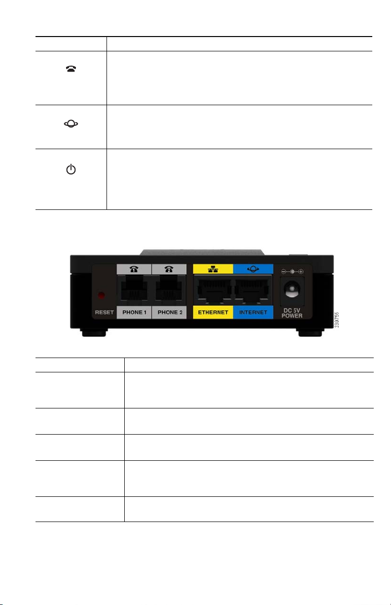
Back Panel
Feature Description
Reset Using a paperclip or similar object, press this button
briefly to restart the unit. Press and hold for 10
seconds to restore the factory default settings.
Phone 1,
Phone 2 (Gray)
Ethernet (Yellow)
SPA122 Only
Internet (Blue) Connect to a broadband network device (DSL or
Power Connect to a power source, using the provided
Cisco SPA100 Series Analog Telephone Adapters 3
Connect to an analog phone, using an RJ-11 phone
cable.
Can be used to connect to a device on your network,
such as a computer, using an Ethernet cable.
cable modem) or a network router, using an Ethernet
cable.
power adapter.
Page 4
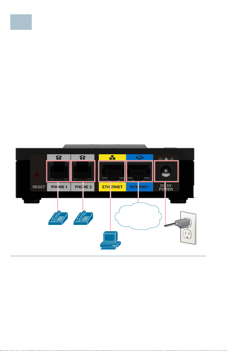
Connecting the Equipment
3
239795
WAN
NOTE For wall-mounting instructions, see Mounting the ATA, page 9.
STEP 1 Connect one end of the provided Ethernet cable to the Internet
(Blue) port. Connect the other end directly to your broadband
network deviceConnect one end of a phone cable to the Phone1
(Gray) port. Connect the other end to your analog phone or fax
machine.
STEP 2 Connect one end of another phone cable to another analog phone
or fax machine. Connect the other end to the Phone 2 (Gray) port.
STEP 3 SPA122 Only: Optionally, connect one end of an Ethernet network
cable to the ETHERNET (Yellow) port of the ATA. Connect the other
end to a device on your network, such as a computer.
STEP 4 Connect the provided power adapter to the Power port.
4 Cisco SPA100 Series Analog Telephone Adapters
Page 5

Configuration and Management of the ATA
4
You can use the web-based configuration utility to set up your ATA. You
also can use the built-in Interactive Voice Response (IVR) system.
Using the Web-Based Configuration Utility
STEP 1 Connect your computer to the same subnet as the ATA. For
example, if the ATA is connected to a LAN port on your router, also
connect your computer to a LAN port on your router.
Note: On SPA122, you can connect your computer to the
ETHERNET (Yellow) port of the ATA.
STEP 2 Power on your computer.
NOTE: Make sure your computer’s Ethernet adapter is set to obtain
an IP address automatically. For more information, refer to the Help
for your operating system.
STEP 3 Start a web browser on your computer.
STEP 4 In the Address bar, enter the IP address of the ATA.
• SPA112: Use the ATA’s IVR or your router’s configuration utility
to find the dynamically assigned IP address of the ATA. For
information about the IVR, see Using the IVR for
Administration, page 6.
• SPA122: In the Address bar, enter: 192.168.15.1
Note: 192.168.15.1 is the default local IP address of the ATA.
STEP 5 To log in for the first time, enter the default username, admin, and
the default password, admin. The password is case sensitive.
STEP 6 Enter the Connection Type and settings required by your Internet
Service Provider. Types include DHCP (the default option),
Static IP, and PPPoE (required for most DSL service). After
entering these settings, click Submit to establish your
Internet connection.
STEP 7 Use the menus to configure your settings, as needed. For more
information, see the ATA Administration Guide. (Documentation
links are provided in Where to Go From Here, page 11.)
Cisco SPA100 Series Analog Telephone Adapters 5
Page 6

Using the IVR for Administration
An IVR system is available to help you to configure and manage your ATA.
You can use the telephone keypad to select options and to make your
entries.
To access the IVR menu:
STEP 1 Connect an analog phone to the Phone port of the ATA.
STEP 2 Press the star key four times: ****
STEP 3 After the greeting plays, press the keys on the phone keypad to
select your options.
STEP 4 Enter the code for the desired action. See the IVR Actions table for
details.
TIPS:
• Enter the numbers slowly, listening for the audio confirmation before
entering the next number.
• After you select an option, press the # (pound) key.
• To exit the menu, hang up the telephone or enter 3948# to exit.
• After entering a value, such as an IP address, press the # (pound) key to
indicate that you have finished your selection. To save the new setting,
press 1. To review the new setting, press 2. To re-enter the new setting,
press 3. To cancel your entry and return to the main menu, press
* (star).
• While entering a value, you can cancel the changes by pressing the
(star) key twice within half a second. Be sure to pres s the key quickly, or
* will be treated as a decimal point entry.
the
• If the menu is inactive for more than one minute, the ATA times out. You
will need to re-enter the menu by pressing the star key four times:
Your settings take effect after you hang up the telephone or exit the IVR.
The ATA may reboot at this time.
• To enter the decimal points in an IP address, press the
example, to enter the IP address 191.168.1.105, perform the following
tasks:
–Press these keys: 191
–Press the # (pound) key to indicate that you have finished
entering the IP address.
–Press 1 to save the IP address or press the
your entry and return to the main menu.
6 Cisco SPA100 Series Analog Telephone Adapters
*168*1*105.
* (star) key. For
* (star) key to cancel
*
****.
Page 7

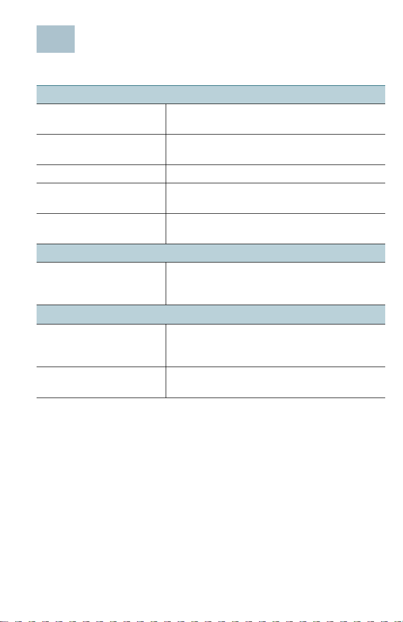
IVR Actions
IVR Action Menu
Option
Enter IVR Menu
Check Internet Connection
Ty pe
Set Internet Connection Type 101 DHCP: 0
Check Internet IP Address
(WAN port)
Set Static IP Address (WAN) 111 Enter the IP address by using
Check Network Mask 120
Set Network Mask 121
Check Gateway IP Address 130
****
100
110
Choices and Instructions
Static IP: 1
PPPoE: Press 2
PPPoE, DHCP: Press 3
DHCP, PPPoE: Press 4
numbers on the telephone
key pad. Use the
when entering a decimal
point.
Note: This option is available
only after you choose Static
IP as the Internet Connection
Type, through option 101.
To enter the value, press
numbers on the telephone
key pad. Press the
to enter a decimal point.
Note: This option is available
only after you choose Static
IP as the Internet Connection
Type, through option 101.
* (star) key
* (star) key
Cisco SPA100 Series Analog Telephone Adapters 7
Page 8

IVR Action Menu
Option
Set Gateway IP Address 131 To enter the value, press
Check MAC Address 140
Check Firmware Version 150
Check Primary DNS Server
Setting
Set Primary DNS Server 161 To enter the value, press
Check Internet web server
port
SPA122 only: Check LAN IP
address (Ethernet port)
Announce Line 1 SIP
Tr an sp or t
Set Line 1 SIP Transport 1911 0: UDP
160
170
210
1910
Choices and Instructions
numbers on the telephone
key pad. Press the
to enter a decimal point.
Note: This option is available
only after you choose Static
IP as the Internet Connection
Type, through option 101.
numbers on the telephone
key pad. Press the
to enter a decimal point.
Note: This option is available
only after you choose Static
IP as the Internet Connection
Type, through option 101.
1: TC P
* (star) key
* (star) key
2: TLS
Check Line 2 SIP Transport 1920
Set Line 2 SIP Transport 1921 0: UDP
1: TC P
2: TLS
Exit IVR 3948
Allow or prevent WAN access
to the administration web
server
8 Cisco SPA100 Series Analog Telephone Adapters
7932 1: Enable
0: Disable
Page 9

IVR Action Menu
5
Option
Factory Reset of Unit
WARNING: All non-default
settings will be lost. This
includes network and service
provider data.
Reboot of Voice System 732668
User Factory Reset of Unit
WARNING: All userchangeable non-default
settings will be lost. This may
include network and service
provider data.
73738
RESET
REBOOT
877778 When prompted, press 1 to
Choices and Instructions
When prompted, press 1 to
confirm, or press
cancel. After you hear “Option
successful,” hang up the
phone. The ATA reboots.
After you hear “Option
successful,” hang up the
phone. The ATA reboots.
confirm, or press
cancel. After you hear “Option
successful,” hang up the
phone. The ATA reboots.
Mounting the ATA
You can place the ATA on a desktop or mount it on a wall.
* (star) to
* (star) to
CAUTION To prevent the ATA from overheating, do not operate it in an
area that exceeds an ambient temperature of 104°F (40°C).
Desktop Placement
Place the ATA on a flat surface near an electrical outlet.
WARNING Do not place anything on top of the ATA; excessive weight
could damage it.
Wall Mounting
The ATA has two wall-mount slots on the bottom panel. To mount the ATA
on a wall, you need mounting hardware (not included). Suggested
hardware is illustrated (not true to scale).
Cisco SPA100 Series Analog Telephone Adapters 9
Page 10

Recommended hardware (not included): Two number-six pan-head
tapping screws, 5/8-in. length, with anchors for sheet rock installation.
5/8 in. (15.8 mm)
WARNING Insecure mounting might damage the ATA or cause injury. Cisco
is not responsible for damages incurred by insecure wallmounting.
To mount the unit to the wall:
STEP 1 Determine where you want to mount the unit. Verify that the surface
is smooth, flat, dry, and sturdy.
STEP 2 Drill two pilot holes into the surface 58 mm apart (about 2.28 in.).
STEP 3 Insert a screw into each hole, leaving a gap of 5 mm (0.1968 in.)
between the underside of each screw head and the surface of the
wall.
STEP 4 Place the unit wall-mount slots over the screws and slide the unit
down until the screws fit snugly into the wall-mount slots.
10 Cisco SPA100 Series Analog Telephone Adapters
Page 11
Support
6
Where to Go From Here
Cisco Small Business
Support Community
Cisco Small Business
Support and Resources
Phone Support Contacts www.cisco.com/go/sbsc
Cisco Small Business
Firmware Downloads
Cisco Small Business
Open Source Requests
Product Documentation
Cisco Small Business
Analog Telephone
Adapters
www.cisco.com/go/smallbizsupport
www.cisco.com/go/smallbizhelp
www.cisco.com/go/software
www.cisco.com/go/smallbiz_opensource_
request
www.cisco.com/go/smallbizvoicegateways
Cisco Small Business
Cisco Partner Central
for Small Business
(Partner Login Required)
Cisco Small Business
Home
www.cisco.com/web/partners/sell/smb
www.cisco.com/smb
Cisco SPA100 Series Analog Telephone Adapters 11
Page 12

Americas Headquarters
Cisco Systems, Inc.
170 West Tasman Drive
San Jose, CA 95134-1706
USA
www.cisco.com
Small Business Support, Global: www.cisco.com/go/sbsc
78-19933-01
Cisco and the Cisco Logo are trademarks of Cisco Systems, Inc. and/or its affiliates in the U.S.
and other countries. A listing of Cisco's trademarks can be found at www.cisco.com/go/
trademarks. Third party trademarks mentioned are the property of their respective owners.
The use of the word partner does not imply a partnership relationship between Cisco and any
other company. (1005R)
© 2011 Cisco Systems, Inc. All rights reserved.
 Loading...