

Page 1
QUICK START GUIDE
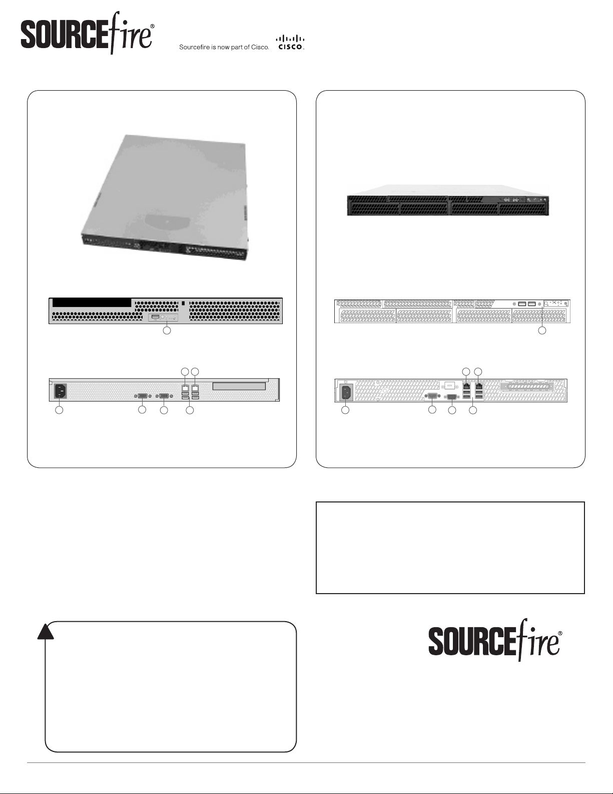
Defense Center 750
DC750 (Rev 1)
Front
(A) Front Panel Controls and USB Port
Back
DC750 (Rev 2)
Front
A
(A) Front Panel Controls and USB Ports
Back
E
F
E
F
A
C
D
B
(B) Power Supply
(C) Serial Port
(D) VGA Port
G
(E) Management Interface
(F) Alternate eStreamer Interface
(G) USB Ports
Included items:
Sourcere DC750 (Rev 1) or DC750 (Rev 2)•
one power cord•
one straight-through Cat 5e Ethernet cable•
rack-mounting kit•
Required items:
athead and Phillips screwdrivers for the •
rack-mounting kit
laptop or monitor and keyboard to connect •
directly to the Defense Center
WARNING!
!
This Sourcere Defense Center should be installed and maintained
by qualied personnel only. Keep in mind the following safety
information to avoid system damage or personal injury:
Remove all factory packaging before using the Defense Center.•
Provide adequate ventilation to prevent overheating. Do not •
cover or block vents, or otherwise enclose the Defense Center.
The Defense Center must be properly grounded when •
connecting power to the power outlet.
At all times, keep the chassis area free from dust.•
Lifting the chassis for rack installation may require two people, •
as the unit is heavy.
To avoid electrical shock, do not open or remove the chassis •
covers or metal parts without proper instruction.
C
D
B
(B) Power Supply
(C) Serial Port
(D) VGA Port
G
(E) Management Interface
(F) Alternate eStreamer Interface
(G) USB Ports
Thank you for choosing Sourcere.
Before installing this Defense Center, download and
follow the instructions in the Sourcere Support
Welcome Kit (https://support.sourcere.com)
to get started with Sourcere Support, and to set up
your Customer Center account.
9770 Patuxent Woods Drive
Columbia, MD 21046 USA
800.917.4134 | +1.410.423.1901
support@sourcere.com
©2014 Cisco and/or its afliates.
All rights reserved.
Page 1 of 4©2014 Cisco and/or its afliates. All rights reserved.
2014-5.3-2
Page 2

DC750
Installing the Defense Center
The Sourcere 3D System is delivered on different hardware platforms that you can
rack-mount. When you install a Defense Center, make sure that you can access the
Defense Center’s console for initial setup.
You can access the console for the rst conguration of a new Defense Center using a
keyboard and monitor with KVM, or using an Ethernet connection to the management
interface.
Keyboard and Monitor/KVM
You can connect a USB keyboard and VGA monitor to any Sourcere Defense Center,
which is useful for rack-mounted Defense Centers connected to a keyboard, video, and
mouse (KVM) switch.
IMPORTANT! Do not use a KVM switch with USB mass storage to access the Defense
Center because the Defense Center may attempt to use the mass storage device as a
boot device.
INSTALLATION
Ethernet Connection to Management Interface
Congure a local computer, which must not be connected to the internet, with the
following network settings:
IP address: • 192.168.45.2
netmask: • 255.255.255.0
default gateway: • 192.168.45.1
Using an Ethernet cable, connect the network interface on the local computer to the
management interface on the Defense Center. To interact with the Defense Center, use
terminal emulation software such as HyperTerminal or XModem. The settings for this
software are as follows:
9600 baud•
8 data bits•
no parity checking•
1 stop bit•
no ow control•
Note that the management interface on a physical Sourcere Defense Center
is precongured with a default IPv4 address. However, you can recongure the
management interface with an IPv6 address as part of the setup process.
Quick Start Guide - DC750
Page 2 of 4
2014-5.3-2
Page 3

DC750
Installation Procedure
To install the Defense Center:
Mount the Defense Center in your rack using the mounting kit and its supplied 1.
instructions.
Connect to the Defense Center using either a keyboard and monitor or an Ethernet 2.
connection.
If you are using a keyboard and monitor to set up the Defense Center, use an •
Ethernet cable now to connect the management interface to a protected network
segment.
If you plan to perform the initial setup process by connecting a computer directly •
to the Defense Center’s physical management interface, you will connect the
management interface to the protected network when you nish setup.
Attach the power cord to the Defense Center and plug into a power source.3.
INSTALLATION
If your Defense Center has redundant power supplies, attach power cords to both power
supplies and plug them into separate power sources.
Turn on the Defense Center.4.
If you are using a keyboard and monitor to set up the Defense Center, continue with •
Conguring Network Setting Using a Script in the
Guide
If you are using a direct Ethernet connection to set up the Defense Center, conrm •
that the link LED is on for both the network interface on the local computer and the
management interface on the Defense Center. If the management interface and
network interface LEDs are not lit, try using a crossover cable. For more information,
see Cabling Inline Deployments on Copper Interfaces in the
Installation Guide
After you have congured network settings, make sure your Defense Center is connected 5.
to the protected management network with an Ethernet cable, and continue the initial
setup with Initial Setup Page: Defense Centers in the
Guide
.
.
.
Sourcere 3D System Installation
Sourcere 3D System
Sourcere 3D System Installation
Quick Start Guide - DC750
Page 3 of 4
2014-5.3-2
Page 4

DC750
LEDs, SPECIFICATIONS, REGULATORY, and SECURITY
LEDs
Front Panel and Front Panel LEDs
DC750 (Rev 1)
A
B
F
D
E
C
A USB port
G
B Power button
C System status LED
D Power LED
E Fixed disk drive status LED
F NIC 1 activity status LED
G NIC 2 activity status LED
LED Color Indications
System status A green light indicates that the system is operating normally.
Power A green light indicates there is power.
Hard Drive Activity A blinking green light indicates that the xed disk drive is active.
NIC Activity A blinking green light indicates there is activity.
A blinking green light indicates that the system is operating in a degraded condition.
DC750 (Rev 1) only: A blinking amber light indicates that the system is in a non-critical error condition.
DC750 (Rev 1) only: An amber light indicates that the system is in a critical or non-recoverable error condition.
No light indicates POST/system stop.
IMPORTANT! - DC750 (Rev 1) only
Amber status light takes precedence over green. When amber is on or blinking, green is off.
A blinking green light indicates the system is sleeping.
No light indicates there is no power.
DC750 (Rev 1) only: An amber light indicates there is a xed disk drive fault.
No light indicates either there is no drive activity, or the system is powered off or sleeping.
No light indicates there is no activity.
Management Interface LEDs
DC750 (Rev 2)
A
B
D
E
C
G
A ID button with ID LED
F
B Non-maskable interrupt button
C NIC activity status LEDs
D Reset button
E Fixed disk drive status LED
F Power button with power LED
G System status LED
LED Description
Left (Link) Indicates whether the link is up. If the LED is on, the link is up; if the LED is off, there is no link.
Right (Activity) Indicates activity on the port. A blinking LED indicates activity; if the LED is off, there is no activity.
Hardware Specications
Physical and Environmental Parameters
Parameter DC750 (Rev 1) DC750 (Rev 2)
Form Factor 1U 1U
Dimensions (D x W x H) 20.0” x 16.93” x 1.67” (50.8 cm x 43.0 cm x 4.24 cm) 21.8” x 17.25” x 1.67” (55.37 cm x 43.82 cm x 4.24 cm)
Max Weight 33 lbs (15 kg) 33 lbs (15 kg)
Power Supply 350 W power supply at 120 VAC
Operating Temperature 50°F to 95°F (10°C to 35°C) with the maximum rate of change
Non-Operating Temperature -40°F to +158°F (-40°C to +70°C) -40°F to +158°F (-40°C to +70°C)
Non-Operating Humidity 90%, non-condensing at 95°F (35°C) 90%, non-condensing at 82.4°F (28°C)
Acoustic Noise <7.0 dBA (rack mount) in an idle state at typical ofce ambient
Operating Shock No errors with half a sine wave shock of 2G (with 11
Package Shock Operational after 24” (61 cm) free fall; cosmetic damage may
Air Flow Front to back Front to back
ESD +/- 12kV for air discharge and 8 K for contact +/- 12kV for air discharge and 8 K for contact
System Cooling Requirements 1660 BTU/hour 1660 BTU/hour
9.5 Ampere max. at 110 Volts, 50/60 Hz
4.75 Ampere max. at 220 volts, 50/60 Hz
not to exceed 18°F (10°C)
temperature
millisecond duration)
be present (chassis weight: 40-80 lbs / 18-36 kg)
Regulatory Conformance
This Sourcere Defense Center conforms to multiple national and international standards. For a full list of regulatory compliance, see the
Sourcere 3D System Installation Guide
.
Security Considerations
Before you install your Defense Center, Sourcere recommends that you consider the following:
Locate your Defense Center in a lockable rack within a secure location that prevents access by unauthorized personnel.•
Allow only trained and qualied personnel to install, replace, administer, or service the Defense Center.•
Always connect the management interface to a secure internal management network that is protected from unauthorized access.•
250 W power supply at 120 VAC
6.0 Ampere max. at 110 Volts, 50/60 Hz
3.0 Ampere max. at 220 volts, 50/60 Hz
50°F to 95°F (10°C to 35°C) with the maximum rate of change
not to exceed 18°F (10°C)
<7.0 dBA (rack mount) in an idle state at typical ofce ambient
temperature
No errors with half a sine wave shock of 2G (with 11
millisecond duration)
Operational after 24” (61 cm) free fall; cosmetic damage may
be present (chassis weight: 40-80 lbs / 18-36 kg)
Quick Start Guide - DC750
Page 4 of 4
2014-5.3-2
 Loading...