

Page 1

Products & Services
Cisco Small Form-Factor Pluggable (SFP) Transceiver Modules Maintenance
and Troubleshooting
Document ID: 72370
Contents
Introduction
Prerequisites
Requirements
Components Used
Conventions
Cisco SFP Transceiver Modules
Cisco Fast Ethernet SFP Modules
Cisco Gigabit Ethernet SFP Modules
Cisco CWDM Transceiver Modules
Supported Catalyst
Catalyst 6500/6000 Series
Catalyst 4500 Series
Catalyst 3750 Series
Catalyst 3750
Catalyst 3560 Series
Catalyst 3560
Catalyst 2970 Series
Catalyst 2960 Series
Catalyst 2950 Series
Catalyst 2948G Series
Catalyst 2940 Series
Catalyst Express 500 Series
Safety Guidelines
Laser Safety
Guidelines for Handling SFPs
Required Tools
Install and Remove SFP Transceiver
Types of SFP Transceiver Latches
Install a SFP Transceiver Module
Remove SFP Transceiver Modules
Cabling Specfications
Configure SFPs
Configure Interface Speed and Duplex
Use Third Party SFP Modules
Connect a SFP Module to a GBIC
Troubleshoot
The Link Does Not Come Up in the Sup720
X6748-SFP, Even After a Reboot
The WS
Cisco IOS Software
Speeds Supported by the
Switch
Use the 10
a Catalyst 4500 Series Switch
SPF Ports of the WS
SFP Interfaces of X2/Twin Gigabit
The
Catalyst Switches
Cisco Support Community
Related Information
Switches
-E Series
-E Series
Modules
Mode
Module
SFPs
Module with Line Cards WS-X6724-SFP and WS-
-X6724-SFP Module with DFC3A Resets in Cisco Catalyst 6500 Switches That Run
1000BASE-T(GLC-T) SFP Module on the Cisco Catalyst 3750 Series
-Gigabit Ethernet and Gigabit Ethernet SFP Ports of a SupII+10GE or SupV-10GE in
-X4506-GB-T Module or the WS-X4948 Chassis Do Not Come Up
Converter Do Not Come Up
Links Do Not Come Up in Cisco 3800 Series Routers with SPFs for Connecting to Cisco
- Featured Conversations
Introduction
This document provides information about the deployment and troubleshooting of Cisco Small FormFactor Pluggable (SFP) Transceiver Modules in Cisco Catalyst Switches. Cisco Transceiver Modules
support Ethernet, Sonet/SDH and Fibre Channel applications across all Cisco switching and routing
platforms. Cisco pluggable transceivers offer a convenient and cost effective solution for the adoption in
data centers, campuses, metropolitan area access and ring networks, and storage area networks.
Prerequisites
Requirements
There are no specific requirements for this document.
Components Used
The information in this document is based on the Cisco SFP Transceiver Modules.
Page 2
The information in this document was created from the devices in a specific lab environment. All of the
devices used in this document started with a cleared (default) configuration. If your network is live, make
sure that you understand the potential impact of any command.
Conventions
Refer to Cisco Technical Tips Conventions for more information on document conventions.
Cisco SFP Transceiver Modules
The Cisco portfolio of hot pluggable interfaces offers a rich set of choices in terms of speeds, protocols,
reaches and supported transmission media.
Cisco Fast Ethernet SFP Modules
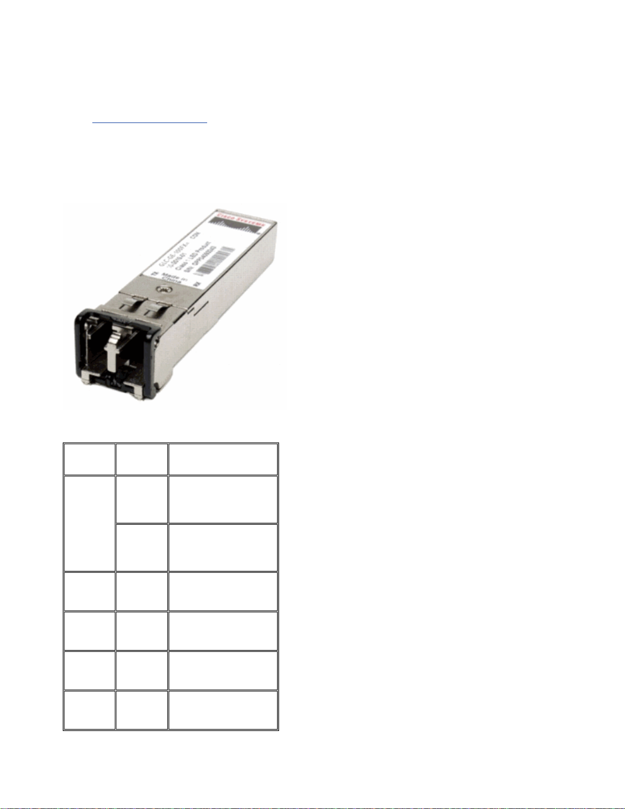
The Cisco 100BASE-X SFP comes in six configurations:
Cisco 100M
Ethernet
SFP
Cisco
100BASE-FX
SFP
Cisco
100BASELX10 SFP
Cisco
100BASEBX10 SFP
Cisco
100BASE-EX
SFP
Cisco
100BASE-ZX
SFP
Part
Number
GLC-FE100FX
GLC-GE100FX
GLC-FE100LX
GLC-FE100BX-D
GLC-FE100BX-U
GLC-FE100EX
GLC-FE100ZX
Description
Operates on ordinary
multimode fiber-optic (MMF)
link spans up to 2 kilometers
long. For 100Mbps Ethernet
ports
Operates on ordinary
multimode fiber-optic (MMF)
link spans up to 2 kilometers
long. For Gigabit Ethernet
ports
Operates on ordinary singlemode fiber-optic (SMF) link
spans up to 10 kilometers
long.
Operates on ordinary SMF
single-strand link spans up to
10 kilometers long.
Operates on ordinary singlemode fiber-optic (SMF) link
spans up to 40 kilometers
long.
Operates on ordinary singlemode fiber-optic (SMF) link
spans up to 80 kilometers
long.
Cisco Gigabit Ethernet SFP Modules
Page 3
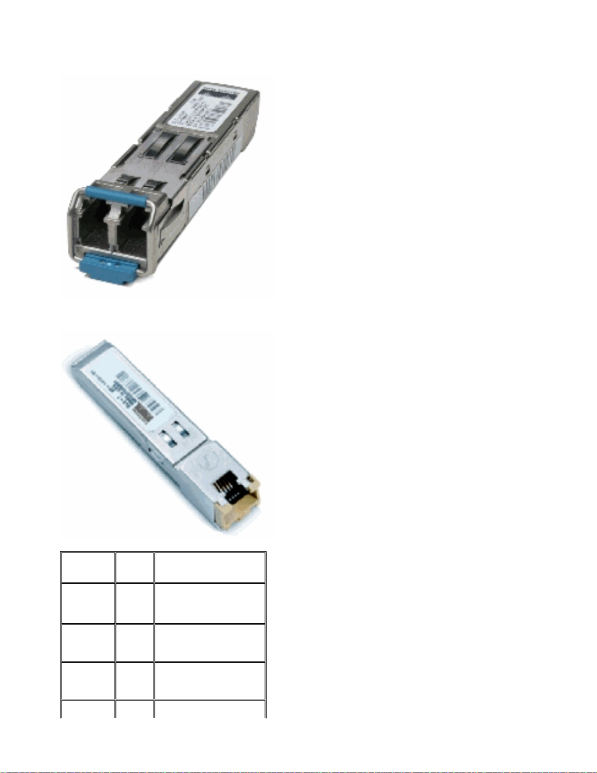
SFP Transceiver Module [Fiber-Optic LC Connector]
1000BASE-T SFP Transceiver Module [RJ-45 Connector]
Cisco
Gigabit
Ethernet SFP
Cisco
1000BASE-SX
SFP
Cisco
1000BASELX/LH SFP
Cisco
1000BASE-ZX
SFP
Part
Number
GLC-SX-
1
MM
SFP-GE-
2
S
GLC-LH-
1
SM
SFP-
2
GE-L
GLC-ZX-
1
SM
SFP-
2
GE-Z
Description
Operates on 50 μm multimode
fiber links up to 550 m and on
62.5 μm FDDI-grade multimode
fibers up to 220 m.
Operates on standard singlemode fiber-optic link spans of up
to 10 km and up to 550 m on
any multimode fibers.
Operates on standard singlemode fiber-optic link spans of up
to approximately 70 km in
length.
Operates on a single strand of
Page 4
A
standard single-mode fiber. A
Cisco
1000BASEBX10-D &
1000BASEBX10-U SFP
GLC-BX-
2
D
GLC-
BX-U
1000BASE-BX10-D device is
always connected to a
1000BASE-BX10-U device with
a single strand of standard
2
single-mode fiber with an
operating transmission range up
to 10 km.
Cisco
1000BASE-T
SFP
GLC-T
SFP-GE-
3
T
1000BASE-T SFP Transceiver
Module for Category 5 copper
wire.
1
Without Digital Optical Monitoring (DOM)
2
With Digital Optical Monitoring (DOM)
3
NEBS 3 ESD
For more information about support for Gigabit Ethernet installations on links of multimode fibers, refer to
Cisco
Support for Gigabit Ethernet Deployments with Multimode Fiber Links up to 2 km.
Cisco CWDM Transceiver Modules
Cisco Coarse Wavelength Divison Multiplexing (CWDM) SFP is a hot-swappable input/output device
that plugs into an SFP port or slot of a Cisco switch or router, and links the port with the fiber-optic
network. The Cisco CWDM SFPs are multirate parts that support both Gigabit Ethernet and Fibre Channel
(1 Gigabit and 2 Gigabit).
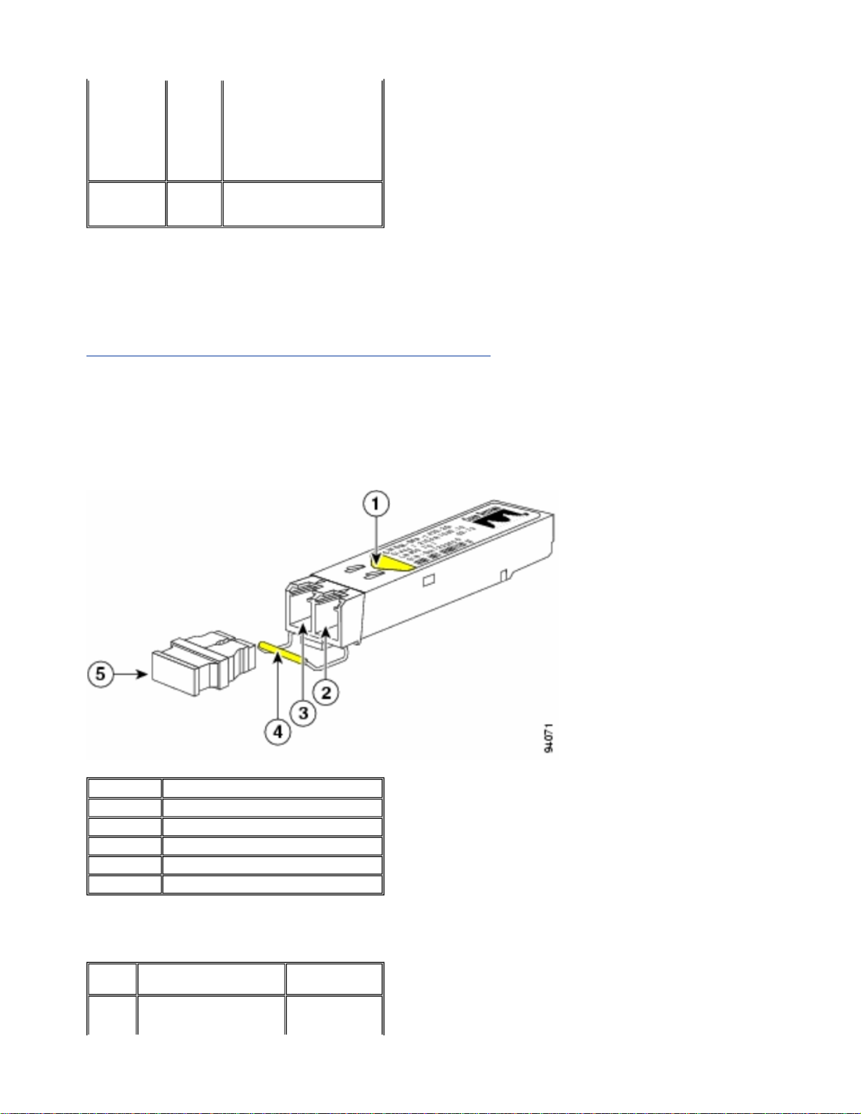
CWDM SFP Module [Yellow-coded CWDM-SFP-1550 shown]
S. No. Description
1 Color arrow on label
2 Receive optical bore
3 Transmit optical bore
4 Color coded bale clasp
5 Optical bore dust plug
CWDM SFPs come in eight wavelengths that range from 1470 nm to 1610nm. Color markings on the
devices identify the wavelength to which the Gigabit Ethernet channel is mapped. This table lists the SFPs
with their wavelength and color codes.
Part
Number
CWDMSFP-
Description Color Code
Cisco CWDM 1470-nm SFP;
Gigabit Ethernet and 1 and 2
Gray
Page 5

1470 Gb Fibre Channel
CWDMSFP1490
CWDMSFP1510
CWDMSFP1530
CWDMSFP1550
CWDMSFP1570
CWDMSFP1590
CWDMSFP1610
Cisco CWDM 1490-nm SFP;
Gigabit Ethernet and 1 and 2
Gb Fibre Channel
Cisco CWDM 1510-nm SFP;
Gigabit Ethernet and 1 and 2
Gb Fibre Channel
Cisco CWDM 1530-nm SFP;
Gigabit Ethernet and 1 and 2
Gb Fibre Channel
Cisco CWDM 1550-nm SFP;
Gigabit Ethernet and 1 and 2
Gb Fibre Channel
Cisco CWDM 1570-nm SFP;
Gigabit Ethernet and 1 and 2
Gb Fibre Channel
Cisco CWDM 1590-nm SFP;
Gigabit Ethernet and 1 and 2
Gb Fibre Channel
Cisco CWDM 1610-nm SFP;
Gigabit Ethernet and 1 and 2
Gb Fibre Channel
Violet
Blue
Green
Yellow
Orange
Red
Brown
Supported Catalyst Switches
This section lists the Cisco Catalyst Switches that support the Cisco SFP Transceiver Modules.
Note: If a module / device supports both 100M SFP and Gigabit Ethernet SFP transceiver modules, they
can be used at the same time on appropriate ports. However, aggregating (channelling) different types of
transceiver modules is not supported.
Catalyst 6500/6000 Series
Modules 100M SFPs
GLC-FE-100FX
GLC-FE-100LX
WS-X6148-FESFP
WS-SUP720
WS-SUP328GE-3B WSSUP32-10GE3B WS-X6724SFP WS-X6748SFP
GLC-FE100BX-D GLCFE-100BX-U
GLC-FE-100EX
GLC-FE-100ZX
-
Catalyst 4500 Series
Modules 100M SFPs
GLC-FE100FX GLC-
WS-X4248-FESFP
WS-X4013+TS
WS-X4506-GB-T
4
WS-X4516-
10GE
FE-100LX
GLC-FE100BX-D
GLC-FE100BX-U
-
Gigabit
Ethernet
SFPs
- -
GLC-T GLCSX-MM GLCLH-SM GLCZX-SM GLCBX-D GLCBX-U
Gigabit
Ethernet
SFPs
- -
GLC-SX-MM
GLC-LH-SM
GLC-ZX-SM
GLC-BX-D
GLC-BX-U
CWDM
SFPs
All
CWDM
SFPs
CWDM
SFPs
All
CWDM
SFPs
Page 6

WSX4013+10GE
WS-4448-GBSFP
WS-X45-Sup6-E -
-
-
Catalyst 3750 Series
GLC-LH-SM
GLC-ZX-SM
GLC-BX-D
GLC-BX-U
GLC-T GLCSX-MM GLCLH-SM GLCZX-SM GLCBX-D GLC-BXU
GLC-T GLCSX-MM GLCLH-SM GLCZX-SM
All
CWDM
SFPs
-
All
CWDM
SFPs
Switches
WS-C3750-24PS WSC3750-24TS WS-C375048PS WS-C3750-48TS
WS-C3750-24FS-S WSC3750G-12S WSC3750G-24PS WSC3750G-24TS WSC3750G-48PS WSC3750G-48TS WSC3750G-24TS-E1U WSC3750G-24TS-S1U
Catalyst 3750-E Series
Switches
WS-C3750E-24TD
WS-C3750E-24PD
WS-C3750E-48TD
WS-C3750E-48PD
WS-C3750E-48PD-F
Catalyst 3560 Series
Switches 100M SFPs
GLC-FE100FX
WS-C3560-8PC
WS-C3560-24PS
WS-C3560-48PS
WS-C3560-24TS
WS-C3560-48TS
WS-C3560G-24PS
WS-C3560G-24TS
WS-C3560G-48PS
WS-C3560G-48TS
GLC-FE100LX GLCFE-100BXD GLC-FE100BX-U
GLC-GE100FX
GLCGE100FX
100M
SFPs
GLCGE100FX
100M
SFPs
Gigabit
Ethernet
GLC-T GLCSX-MM GLCLH-SM GLCZX-SM GLCBX-D GLCBX-U
Gigabit
Ethernet SFPs
GLC-T GLC-SXMM GLC-LH-SM
GLC-ZX-SM
GLC-BX-D GLCBX-U
Gigabit
Ethernet
GLC-SX-MM
GLC-LH-SM
GLC-ZX-SM
GLC-BX-D
GLC-BX-U
GLC-T GLCSX-MM GLCLH-SM GLCZX-SM GLCBX-D GLCBX-U
SFPs
SFPs
CWDM
SFPs
All
CWDM
SFPs
CWDM
SFPs
All
CWDM
SFPs
CWDM
SFPs
All
CWDM
SFPs
All
CWDM
SFPs
Catalyst 3560-E Series
Switches
WS-C3560E-24TD
WS-C3560E-24PD
100M
SFPs
GLC-
Gigabit
Ethernet SFPs
GLC-T GLC-SXMM GLC-LH-SM
CWDM
SFPs
All
Page 7
WS-C3560E-48TD
WS-C3560E-48PD
WS-C3560E-48PD-F
Catalyst 2970 Series
GE100FX
GLC-ZX-SM
GLC-BX-D GLCBX-U
CWDM
SFPs
Switches
WSC2970G24TS
100M
SFPs
GLC-GE100FX
Catalyst 2960 Series
Switches 100M SFPs
WS-C296024TC-L WSC2960-48TC-L
WS-C2960G24TC-L
GLC-GE-100FX
GLC-FE-100FX
GLC-FE-100LX
GLC-FE-100BXD GLC-FE100BX-U
Catalyst 2950 Series
Switches
WS-C2950ST-8 LRE
WS-C2950ST-24 LRE
WS-C2950ST-24
LRE997
Catalyst 2948G Series
Gigabit Ethernet
SFPs
GLC-T GLC-SX-MM
GLC-LH-SM GLC-ZXSM
Gigabit
Ethernet
SFPs
GLC-SX-MM
GLC-LH-SM
GLC-ZX-SM
GLC-BX-D
GLC-BX-U
100M
SFPs
-
Gigabit
Ethernet SFPs
GLC-T GLC-SXMM GLC-LH-SM
GLC-ZX-SM
CWDM
SFPs
All CWDM
SFPs
CWDM
SFPs
All
CWDM
SFPs
CWDM
SFPs
All
CWDM
SFPs
Switches
WS-C2948GGE-TX
100M
SFPs
-
Gigabit Ethernet
SFPs
GLC-T GLC-SX-MM
GLC-LH-SM GLC-ZXSM
CWDM
SFPs
All CWDM
SFPs
Catalyst 2940 Series
Switches
WS-C29408TF-S
100M
SFPs
-
Gigabit Ethernet
SFPs
GLC-T GLC-SX-MM
GLC-LH-SM GLC-ZXSM
CWDM
SFPs
-
Catalyst Express 500 Series
Gigabit
Switches 100M SFPs
Ethernet
SFPs
WS-CE50024LC WSCE500-24PC
WS-CE500G12TC
Refer to these documents for other types of devices which support Cisco SFP Transceiver Modules:
z Cisco 100-Megabit Ethernet SFP Modules Compatibility Matrix
GLC-GE-100FX
GLC-FE-100FX
GLC-FE-100LX
GLC-FE-100BX-D
GLC-FE-100BX-U
GLC-SX-MM
GLC-LH-SM
GLC-ZX-SM
CWDM
SFPs
-
z Cisco Gigabit Ethernet Transceiver Modules Compatibility Matrix
Page 8

z Cisco Wavelength Division Multiplexing Transceivers Compatibility Matrix
g
Safety Guidelines
Laser Safety
Before you install SFP modules in a Cisco device or attempt to operate or service a Cisco device equipped
with SFP modules, you must read and observe the important safety information in this publication. Refer to
the Regulatory Compliance and Safety Information publication or the Site Preparation and Safety Guide
that supports your Cisco device for the complete list of translated safety warnings and agency approvals
that apply to your Cisco device.
The Cisco SFP Transceiver Modules are equipped with a Class 1 Laser, which emits invisible radiation.
Do not stare into open optical ports. These warnings apply to the Cisco SFP modules.
Warning: Class 1 laser product.
Warning: Because invisible laser radiation can be emitted from the aperture of the port when no
fiber is connected, avoid exposure to laser radiation and do not stare into open apertures.
Warning: Laser radiation is present when the system is open and interlocks bypassed.
Warning: Only trained and qualified personnel should be allowed to install, replace, or service this
equipment.
Guidelines for Handling SFPs
Use these guidelines when you work with SFPs:
z Cisco SFP modules are static sensitive. Wear an ESD-preventive wrist strap that is connected to
the chassis in order to prevent ESD damage.
z Cisco SFP modules are dust sensitive. Always store the devices with plugs installed in the optical
bores.
z Do not remove and insert a Cisco SFP module more often than is necessary. Repeated romovals
and insertions of a Cisco SFP module can shorten its useful life.
Required Tools
You need these tools in order to install or remove the SFP transceiver:
z Wrist strap or other personal grounding device to prevent ESD occurrences.
z Antistatic mat or antistatic foam to set the transceiver on.
z Fiber-optic end-face cleaning tools and inspection equipment.
Refer to these documents for complete information on how to inspect and clean fiber-optic
connections:
{ Inspection and Cleaning Procedures for Fiber-Optic Connections
{ Compressed Air Cleaning Issues for Fiber-Optic Connections
Install and Remove SFP Transceiver Modules
This installation section provides the installation instructions for the Cisco SFP Transceiver Modules. The
SFP Transceiver Modules are hot-swappable input/output (I/O) devices that plug into 100BASE and
1000BASE ports, which connects the module port with the fiber-optic or copper network.
You can use any combination of SFP modules that your Cisco device supports. The only restrictions are
each port must match the wavelength specifications on the other end of the cable and the cable must not
exceed the stipulated cable len
th for reliable communications.
Page 9
Note: See the Safety Guidelines section before you install the SFP Transceiver Modules.
g
Types of SFP Transceiver Latches
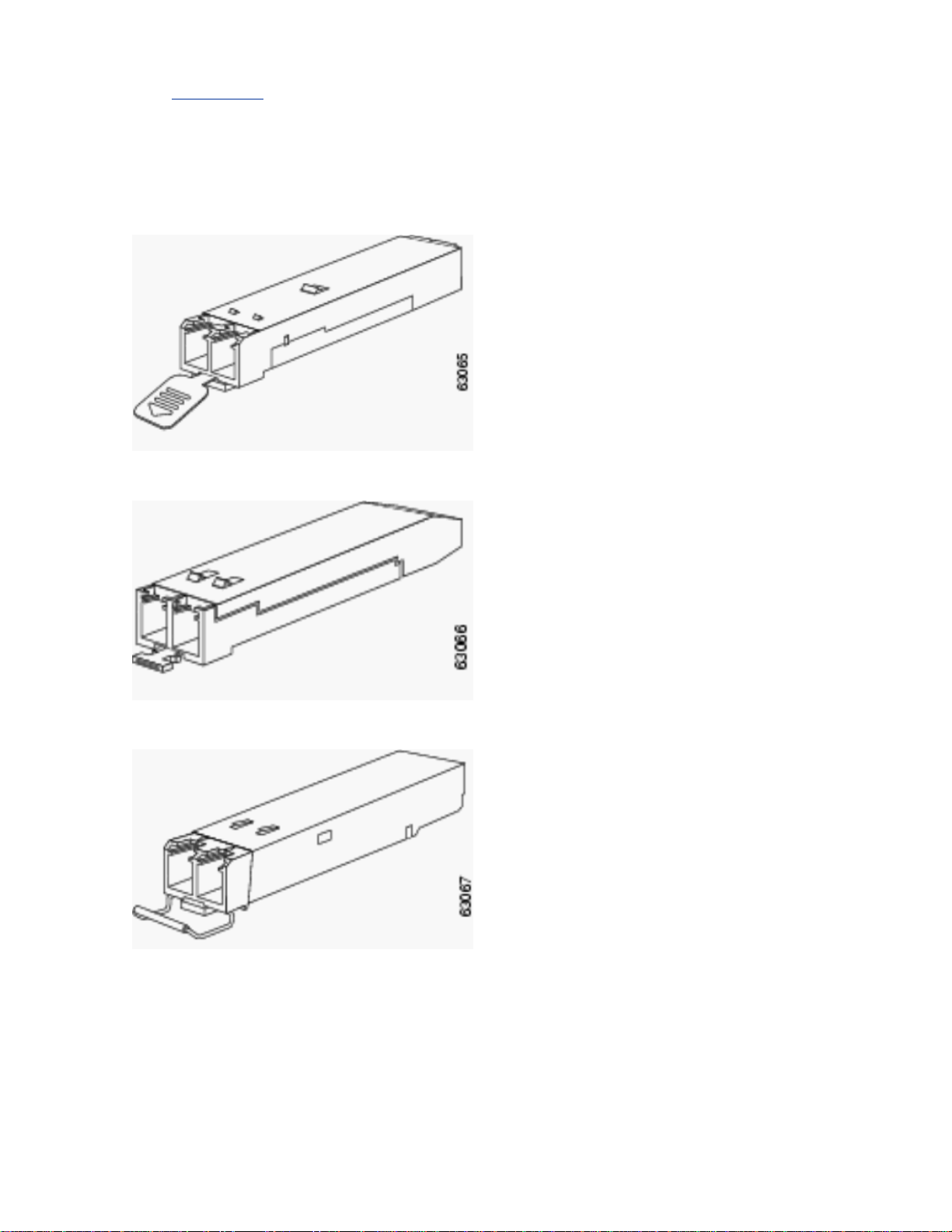
SFP Transceiver Modules can have three types of latching devices to secure an SFP transceiver in a port
socket. Determine which type of latch your SFP transceiver uses before you complete the installation and
removal procedures:
z SFP transceiver with a Mylar tab latch.
z SFP transceiver with an actuator button latch.
z SFP transceiver that has a bale-clasp latch.
Install a SFP Transceiver Module
Complete these steps in order to install a SFP transceiver:
1. Attach an ESD-preventive wrist strap to your wrist and to the ESD ground connector or a bare
metal surface on your chassis.
2. Remove the SFP Transceiver Module from its protective packaging.
Note: Do not remove the optical bore dust plu
s until directed to do so later in the procedure.
Page 10
3. Check the label on the SFP transceiver body to verify that you have the correct model for your
network.
4. Find the send (TX) and receive (RX) markings that identify the top side of the SFP transceiver.
Note: On some SFP transceivers, the TX and RX marking might be replaced by arrowheads that
point from the SFP transceiver connector (transmit direction or TX) and toward the connector
(receive direction or RX).
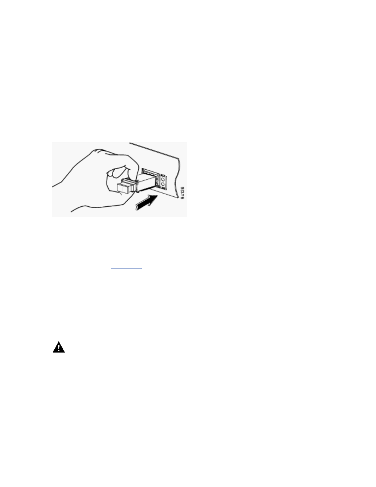
5. Position the SFP transceiver in front of the socket opening.
Note: Different Cisco devices have different SFP module socket configurations. Your Cisco device
could have either a latch-up or a latch-down orientation. Ensure that you are installing the SFP
transceiver in the correct orientation for your Cisco device. Refer to the hardware installation
instructions that came with your Cisco device for more details.
6. Insert the SFP transceiver into the socket until you feel the SFP Transceiver Module connector
snap into place in the socket connector.
Note: For optical SFP transceivers, before you remove the dust plugs and make any optical
connections, observe these guidelines:
{ Always keep the protective dust plugs on the unplugged fiber-optic cable connectors and the
transceiver optical bores until you are ready to make a connection.
{ Always inspect and clean the LC connector end-faces just before you make any
connections. See the Required Tools
{ Always grasp the LC connector housing to plug or unplug a fiber-optic cable.
section of this document for more information.
7. Remove the dust plugs from the network interface cable LC connectors. Save the dust plugs for
future use.
8. Remove the dust plugs from the SFP transceiver optical bores.
9. Immediately attach the network interface cable LC connector to the SFP transceiver.
10. Connect the 1000BASE-T SFP transceivers to a copper network.
Caution: In order to comply with GR-1089 intrabuilding lightning immunity requirements,
you must use grounded, shielded, twisted-pair Category 5 cabling.
Complete these steps in order to connect the transceivers to a copper network:
a. Insert the Category 5 network cable RJ-45 connector into the SFP transceiver RJ-45
connector.
When you connect to a 1000BASE-T-compatible server, workstation, or router, use four
twisted-pair, straight-through Category 5 cabling for the SFP transceiver port. When you
connect to a 1000BASE-T-compatible switch or repeater, use four twisted-pair, crossover
Category 5 cabling.
b. Insert the other end of the network cable into an RJ-45 connector on a 1000BASE-T-
compatible target device.
11. Observe the port status LED:
Page 11
{ The LED turns green when the SFP transceiver and the target device have an established
your
link.
{ The LED turns amber while STP discovers the network topology and searches for loops.
This process takes about 30 seconds, and then the LED turns green.
{ If the LED is off, the target device might not be turned on, there might be a cable problem, or
there might be a problem with the adapter installed in the target device. Refer to the
Troubleshooting section of your switch hardware guide for solutions to cabling problems.
{ Reconfigure and reboot the target device if necessary.
Remove SFP Transceiver Modules
Complete these steps in order to remove the SFP transceiver:
1. Attach an ESD-preventive wrist strap to your wrist and to the ESD ground connector or a bare
metal surface on your chassis.
2. Disconnect the network fiber-optic cable or network copper cable from the SFP Transceiver Module
connector.
For optical SFP transceivers, immediately reinstall the dust plugs in the SFP transceiver optical
bores and the fiber-optic cable LC connectors.
Tip: For reattachment of fiber-optic cables, note which connector plug is send (TX) and which is
receive (RX).
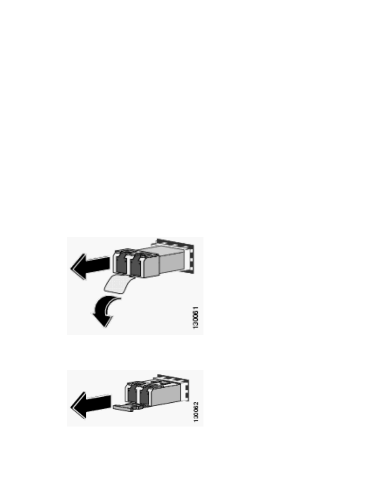
3. Release and remove the SFP Transceiver Module from the socket connector.
{ If the SFP transceiver has a Mylar tab latch, pull the tab gently in a slightly downward
direction until the transceiver disengages from the socket connector, and then pull the SFP
transceiver straight out. Do not twist or pull the Mylar tab because you could detach it from
the SFP transceiver.
{ If the SFP transceiver has an Actuator button latch, gently press the actuator button on
the front of the SFP transceiver until it clicks and the latch mechanism releases the SFP
transceiver from the socket connector. Grasp the actuator button between your thumb and
index finger, and carefully pull the SFP transceiver straight from the module slot.
{ If the SFP transceiver has a Bale-clasp latch, pull the bale out and down to eject the SFP
transceiver from the socket connector. If the bale-clasp latch is obstructed and you cannot
use your index finger to open it, use a small flat-blade screwdriver or another long narrow
instrument to open the bale-clasp latch. Grasp the SFP transceiver between
thumb and
Page 12
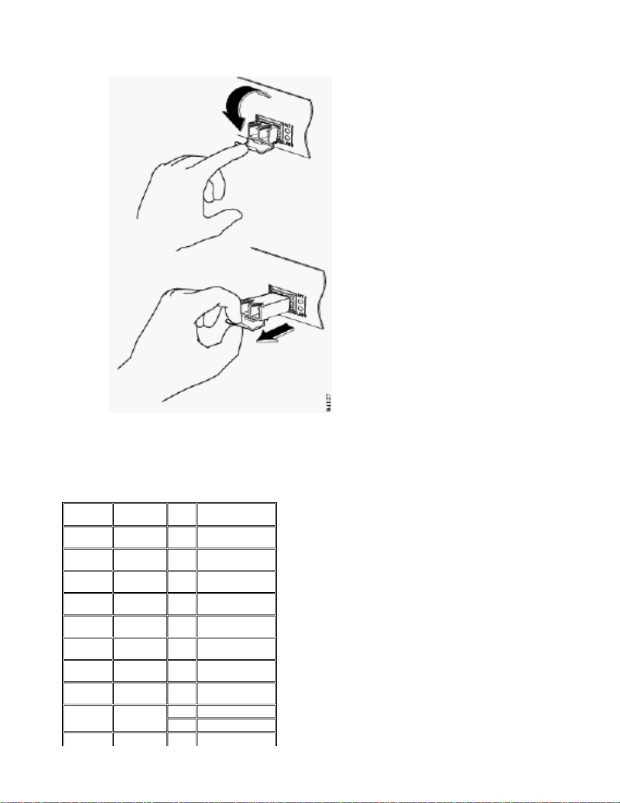
index finger, and carefully remove it from the socket.
4. Place the removed SFP transceiver in an antistatic bag or other protective environment.
Cabling Specfications
This table shows cabling specifications for the Cisco SFP transceivers installed on a FastEthernet / Gigabit
Ethernet SFP port. Note that all SFP ports have LC-type connectors, and the minimum cable distance for
all SFPs listed (MMF and SMF [G.652] is 2 meters [6.5 feet]).
SFP
GLC-FE100FX
GLC-GE100FX
GLC-FE100LX
GLC-FE100BX-U
GLC-FE100BX-D
GLC-FE100EX
GLC-FE100ZX
1000BASESX
1000BASELX/LH
Wavelength
(nm)
1310 MMF 2 km (6562 ft)
1300 MMF 2 km (6562 ft)
1310 SMF 10 km (32,810 ft)
1310 SMF 10 km (32,810 ft)
1550 SMF 10 km (32,810 ft)
1310 SMF 40 km (131,240 ft)
1550 SMF 80 km (262,480 ft)
850 MMF
1300
Fiber
Type
MMF 550 m (1,804 ft)
SMF 10 km (32,8210 ft)
Cable Length
From 220 m (722 ft)
to 550 m (1,804 ft)
Page 13

gg
1000BASEZX
1000BASEBX-D
1000BASEBX-U
1550 SMF
1310 SMF 10 km (32,8210 ft)
1490 SMF 10 km (32,8210 ft)
Approximately 70 km,
which depends on
link loss
Configure SFPs
Configure Interface Speed and Duplex Mode
Ethernet interfaces on the switch operate at 10, 100, or 1000 Mbps, or 10,000 Mbps and in either full- or
half-duplex mode. In full-duplex mode, two stations can send and receive traffic at the same time.
Normally, 10-Mbps ports operate in half-duplex mode, which means that stations can either receive or
send traffic.
You cannot configure speed on SFP module ports, but you can configure speed to not negotiate
(nonegotiate) if connected to a device that does not support autonegotiation. However, when a
1000BASE-T SFP module is in the SFP module port, you can configure speed as 10, 100, or 1000 Mbps,
or auto.
You cannot configure duplex mode on SFP module ports unless a 1000BASE-T SFP module or a
100BASE-FX MMF SFP module is in the port. All other SFP modules operate only in full-duplex mode.
z When a 1000BASE-T SFP module is in the SFP module port, you can configure duplex mode to
auto or full.
z When a 100BASE-FX SFP module is in the SFP module port, you can configure duplex mode to
half or full.
Note: Half-duplex mode is supported on Gigabit Ethernet interfaces. However, you cannot configure these
interfaces to operate in half-duplex mode.
In order to display the information about an optical transceiver installed, use this command: show hw-
module subslot slot/subslot transceiver port idprom.
Use Third Party SFP Modules
The use of third party SFP transceivers with Cisco devices is not supported by Cisco. Cisco-approved SFP
modules have a serial EEPROM that contains the module serial number, the vendor name and ID, a
unique security code, and cyclic redundancy check (CRC). When an SFP module is inserted in the switch,
the switch software reads the EEPROM to verify the serial number, vendor name and vendor ID, and
recomputes the security code and CRC. If the serial number, the vendor name or vendor ID, the security
code, or CRC is invalid, the software generates this security error message and places the interface in an
error-disabled state:
SYS-3-TRANSCEIVER_NOTAPPROVED:Transceiver on port [dec]/[dec] is not supported
Connect a SFP Module to a GBIC Module
The SFP and GBIC is just a connection between the actual laser and the chassis. You need to verify these
in order to connect a SFP module with a GBIC module:
z The type of fiber optic cable used: Single Mode or Multi Mode.
z The type of physical connection required: SC connector, ST connector, etc.
Troubleshoot SFPs
The Link Does Not Come Up in the Sup720 Module with Line Cards WS-X6724-SFP and WSX6748-SFP, Even After a Reboot
This issue is due to an Online Insertion and Removal (OIR) or a reboot that caused the port to move into
the disabled state. This problem most likely occurs in a Supervisor 720 (Sup720) that runs Catalyst OS
(CatOS) versions 8.4(2), 8.4(3) with line cards WS-X6724-SFP and WS-X6748-SFP.
If the port is not in the disabled state before a reboot or OIR, the port remains in operation after the reboot.
However, if the port is in diasbled state before or after a reboot, toggle the negotiation state of the port
before the remote end is connected. Complete these steps in order to to
le the negotiation of the port:
Page 14

1. Disable port negotiation on the port.
A
2. Enable port negotiation on the port to bring the links UP.
port negotiation command enables or disables the link negotiation protocol on the specified port.
The set
lternatively, upgrade the software version to Catalyst OS release which is not affected by the Cisco bug
ID CSCeh46046
(registered customers only) .
The WS-X6724-SFP Module with DFC3A Resets in Cisco Catalyst 6500 Switches That Run
Cisco IOS Software
The WS-X6724-SFP module with Distributed Forwarding Card (DFC3A), that runs Cisco IOS® Software
Release 12.2(18)SXE1 reloads unexpectedly due to a memory allocation failure. Before the reload, the
available memory in the module is around 200k.
This problem is resolved in Cisco IOS Software Releases 12.2(18)SXE4, 12.2(18)SXF and later.
In order to resolve this problem, upgrade the Cisco IOS Software on the switch to the latest maintenance
release, which can be downloaded from the Software
Download (registered customers only) page.
Speeds Supported by the 1000BASE-T(GLC-T) SFP Module on the Cisco Catalyst 3750 Series
Switch
The 1000BASE-T SFP can support 10/100/1000 speeds only on the Cisco Catalyst 2970, 3560, and 3750
Series Switches.
It is also possible to have the port auto-negotiate at a lower speed, or force a slower speed. Issue the
interface capabilities command in order to confirm whether a given GLC-T supports 10/100 speed
show
on a switch.
Output from the show interface capabilities command can confirm whether a GLC-T can be run at a
lower speed. The output also displays the capabilities of the specified interface, which includes the
configurable features and options.
For example, issue this command in order to hardcode the speed of the SFP port to 100Mbps:
Switch(config-if)#speed 100
Use the 10-Gigabit Ethernet and Gigabit Ethernet SFP Ports of a SupII+10GE or SupV-10GE in
a Catalyst 4500 Series Switch
Catalyst 4500 Supervisor II Plus 10GE (WS-X4013+10GE) or Supervisor V 10GE (WS-X4516-10GE) has
four GE uplink interfaces and two 10 GE uplink interface per supervisor. The tables in this section illustrate
how the uplink provides redundancy in a 4507R or 4510R Chassis in various combinations of the two
supervisors in the supervisor slots.
In Cisco IOS Software Release 12.2(25)SG and later on a Catalyst 4507R Series Switch, 10GE and GE
uplinks are concurrently usable on the Supervisor Engine V-10GE (WS-X4516-10GE) and the Supervisor
Engine II+10GE (WS-4013+10GE). In Cisco IOS Software Releases earlier than 12.2(25)SG, you need to
issue the hw
In Cisco IOS Software Release 12.2(25)SG and later, when you use a Supervisor Engine V-10GE (WSX4516-10GE) on a Catalyst 4510R Series Switch, you can select to use both the 10GE and GE uplinks
concurrently, but only with a WS-X4302-GB in slot 10. If either the 10GE or GE uplinks are selected, then
any line card is allowed in slot 10. Issue the hw-module uplink select configuration command to select
the uplinks. In Cisco IOS Software Releases earlier than 12.2(25)SG, you cannot use the 10GE and GE
uplinks concurrently.
Note: Redundancy requires that both supervisor engines in the chassis are of the same supervisor engine
model, and to use the same Cisco IOS software image.
If only 10GE ports are selected for uplink:
-module uplink select configuration command to select either the 10GE or GE uplinks.
Slot1:
Supervisor II
Plus 10GE or
V 10 GE Slot2:
Supervisor II
Plus 10GE or
Uplink
Interface
Slot 1:
Supervisor II
Plus 10GE or
V 10 GE Slot
2: Empty
Slot 1:Empty
Slot2:
Supervisor II
Plus 10GE or
V 10 GE
V 10 GE
Page 15
10GE 1/1 Active N/A Active
10GE 1/2 Active N/A Not Active
10GE 2/1 N/A Active Active
10GE 2/2 N/A Active Not Active
If only GE ports are selected for uplink:
Slot1:
Supervisor II
Plus 10GE or
V 10 GE Slot2:
Supervisor II
Plus 10GE or
Uplink
Interface
Slot 1:
Supervisor II
Plus 10GE or
V 10 GE Slot
2: Empty
Slot 1:Empty
Slot2:
Supervisor II
Plus 10GE or
V 10 GE
V 10 GE
GE 1/3 Active N/A Active
GE 1/4 Active N/A Active
GE 1/5 Active N/A Not Active
GE 1/6 Active N/A Not Active
GE 2/3 N/A Active Active
GE 2/4 N/A Active Active
GE 2/5 N/A Active Not Active
GE 2/6 N/A Active Not Active
If both 10GE and GE ports are selected for uplink:
Slot1:
Supervisor II
Plus 10GE or
V 10 GE Slot2:
Supervisor II
Plus 10GE or
Uplink
Interface
Slot 1:
Supervisor II
Plus 10GE or
V 10 GE Slot
2: Empty
Slot 1:Empty
Slot2:
Supervisor II
Plus 10GE or
V 10 GE
V 10 GE
10GE 1/1 Active N/A Active
10GE 1/2 Active N/A Not Active
10GE 2/1 N/A Active Active
10GE 2/2 N/A Active Not Active
GE 1/3 Active N/A Active
GE 1/4 Active N/A Active
GE 1/5 Active N/A Not Active
GE 1/6 Active N/A Not Active
GE 2/3 N/A Active Active
GE 2/4 N/A Active Active
GE 2/5 N/A Active Not Active
GE 2/6 N/A Active Not Active
Issue these commands in order to enable the 10-Gigabit Ethernet and/or the Gigabit Ethernet SFP uplink
ports:
Switch#conf t
Switch(config)#hw-module uplink select {tengigabitethernet|gigabitethernet|all}
Refer to the Deploying 10-Gigabit Ethernet and a Gigabit Ethernet SFP Ports section of the Catalyst 4500
Series Switch Cisco IOS Software Configuration Guide for more information.
SPF Ports of the WS-X4506-GB-T Module or the WS-X4948 Chassis Do Not Come Up
The WS-X4506-GB-T module has six ports. These ports are dual-mode capable ports. Each port has one
RJ45 based 10/100/1000 Mbps connector and one SFP connector. At a given time, only one of these
Page 16

connectors can be active for a port and the active connector is determined by the interface configuration
y
r
command media-type {rj45 | sfp}.
In a WS-X4948 chassis, the last four ports (ports 45 to 48) are dual-mode capable.
Switch(config)#interface gigabitethernet 5/5
Switch(config-if)#media-type rj45
Enter the show interface capabilities command in order to provide the Multiple Media Types field, which
displays the value no if a port is not dual-mode capable and lists the media types (sfp and rj45) for dualmode capable ports.
SFP Interfaces of X2/Twin Gigabit Converter Do Not Come Up
The default configuration mode is X2, so, if you plan to deploy 10-Gigabit interfaces, you do not need to
configure anything. If you want to deploy Gigabit interfaces, that is, TwinGig Convertors, you must
configure the associated port-group.
First gather the information on how the X2 slots on a module are grouped. Then, to configure the modes of
operation for each X2 port group in which you want to deploy Gigabit, enter the hw-module module m
port-group p select gigabitethernet command. This configuration is preserved across power cycles and
reloads.
Refer to Selecting
X2/TwinGig Convertor Mode for more information.
The Links Do Not Come Up in Cisco 3800 Series Routers with SPFs for Connecting to Cisco
Catalyst Switches
When the SFPs are used to connect a Cisco 3800 Series router to a Cisco Catalyst switch, the link cannot
come up, and the show interface command shows down/down.
In order to overcome this issue, enable autonegotiation on both the router and switch. In order to
permanently resolve the issue, upgrade the Cisco IOS software of the router to release 12.4(8) or later,
which can be downloaded from Cisco
at Cisco bug CSCsc04961
(registered customers only) .
Downloads (registered customers only) . This issue is documented
Cisco Support Community - Featured Conversations
Cisco Support Community is a forum for you to ask and answer questions, share suggestions, and
collaborate with your peers. Below are just some of the most recent and relevant conversations happening
right now.
Want to see more? Join us by clicking here
3548-XL-EN to switch with small... 5 years, 3 months ago
Optical transceiver 1 year, 10 months ago
GLC-LH-SM transceiver modules 9 months, 3 weeks ago
lubosbella 1 Reply
-flores 1 Repl
david
shiva.shivakuma
3 Replies
12-24 port small form factor... 3 months, 1 week ago
cisco 2970 4 years, 6 months ago
GBICs and SFP modules 6 years, 10 months ago
carl_townshend
patrick.beaven
2 Replies
ovt_at_redcenter.ru
4 Replies
1 Reply
Page 17

GBIC AND SFP 3 years, 8 months ago
Jitez1234 8 Replies
3550 EMI image and SFP 3 years, 3 months ago
GBIC/SFP new question.. 3 years, 2 months ago
what is SFP 3 years, 11 months ago
sayhi2shashi
sjonessha
uubozou11
2 Replies
3 Replies
5 Replies
Start A New Discussion
Subscribe
Related Information
z Cisco 100-Megabit Ethernet SFP Modules Compatibility Matrix
z Cisco Gigabit Ethernet Transceiver Modules Compatibility Matrix
z Cisco Wavelength Divi sion Multiplexing Transceivers Compatibility Matrix
z Inspection and Cleaning Procedures for Fiber-Optic Connections
z Compressed Air Cleaning Issues for Fiber-Optic Connections
z Cisco SFPs Product Support
z Cisco CWDM GBIC/SFP Product Support
z Cisco Transceiver Modules Product Support
z Cisco Switches Product Support
z LAN Product Support
z LAN Switching Technology Support
z Technical Support & Documentation - Cisco Systems
Updated: Aug 29, 2008 Document ID: 72370
Contacts | Feedback | Help | Site Map
© 1992-2010 Cisco Systems, Inc. All rights reserved. Terms & Conditions | Privacy Statement | Cookie Policy | Trademarks of Cisco Systems, Inc.
 Loading...