

Page 1

You'll be entered into a quarterly drawing for
free
Cisco Press books by returning this survey! Cisco is dedicated to customer
satisfaction and would like to hear your thoughts on these printed manuals. Please visit the Cisco Product Comments on-line
survey at
www.cisco.com/go/crc
to submit your comments about accessing Cisco technical manuals. Thank you for your time.
General Information
1 Years of networking experience: Years of experience with Cisco products:
2 I have these network types: LAN Backbone WAN
Other:
3 I have these Cisco products: Switches Routers
Other (specify models):
4 I perform these types of tasks: H/W installation and/or maintenance S/W configuration
Network management Other:
5 I use these types of documentation: H/W installation H/W configuration S/W configuration
Command reference Quick reference Release notes Online help
Other:
6 I access this information through: % Cisco.com % CD-ROM % Printed manuals
% Other:
7 I prefer this access method: Cisco.com CD-ROM Printed manuals
Other:
8 I use the following three product features the most:
Document Information
Document Title: Cisco PIX Security Appliance Hardware Installation Guide
Part Number: 78-15170-03 S/W Release (if applicable):
On a scale of 1–5 (5 being the best), please let us know how we rate in the following areas:
The document is complete. The information is accurate.
The information is well organized. The information I wanted was easy to find.
The document is written at my
technical level of understanding.
Please comment on our lowest scores:
The information I found was useful to my job.
Mailing Information
Organization Date
Contact Name
Mailing Address
City State/Province Zip/Postal Code
Country Phone ( ) Extension
E-mail Fax ( )
May we contact you further concerning our documentation? Yes No
You can also send us your comments by e-mail to bug-doc@cisco.com, or by fax to 408-527-8089.
When mailing this card from outside of the United States, please enclose in an envelope addressed to the location on the back of this card with
the required postage or fax to 1-408-527-8089.
Page 2

SAN JOSE CA 95134-9916
BUSINESS REPLY MAIL
FIRST-CLASS MAIL PERMIT NO. 4631 SAN JOSE CA
POSTAGE WILL BE PAID BY ADDRESSEE
DOCUMENT RESOURCE CONNECTION
CISCO SYSTEMS INC
170 WEST TASMAN DR
UNITED STATES
IN THE
NO POSTAGE
NECESSARY
IF MAILED
Page 3

Cisco PIX Security Appliance
Hardware Installation Guide
Corporate Headquarters
Cisco Systems, Inc.
170 West Tasman Drive
San Jose, CA 95134-1706
USA
http://www.cisco.com
Tel: 408 526-4000
800 553-NETS (6387)
Fax: 408 526-4100
Customer Order Number: DOC-7815170=
Text Part Number: 78-15170-03
Page 4

THE SPECIFICATIONS AND INFORMATION REGARDING THE PRODUCTS IN THIS MANUAL ARE SUBJECT TO CHANGE WITHOUT NOTICE. ALL
STATEMENTS, INFORMATION, AND RECOMMENDATIONS IN THIS MANUAL ARE BELIEVED TO BE ACCURATE BUT ARE PRESENTED WITHOUT
WARRANTY OF ANY KIND, EXPRESS OR IMPLIED. USERS MUST TAKE FULL RESPONSIBILITY FOR THEIR APPLICATION OF ANY PRODUCTS.
THE SOFTWARE LICENSE AND LIMITED WARRANTY FOR THE ACCOMPANYING PRODUCT ARE SET FORTH IN THE INFORMATION PACKET THAT
SHIPPED WITH THE PRODUCT AND ARE INCORPORATED HEREIN BY THIS REFERENCE. IF YOU ARE UNABLE TO LOCATE THE SOFTWARE LICENSE
OR LIMITED WARRANTY, CONTACT YOUR CISCO REPRESENTATIVE FOR A COPY.
The following inform ation is for FCC compliance of Class A devices: This equipment has been tested and found to comply with the limits for a Class A digital device, pursuant
to part 15 of the FCC rules. These limits are designed to provide reasonable protection against harmful interference when the equipment is operated in a commercial
environment. This equipment generates, uses, and can radiate radio-frequency energy and, if not installed and used in accordance with the instruction manual, may cause
harmful interference to radio communications. Operation of this equipment in a residential area is likely to cause harmful interference, in which case users will be required
to correct the interference at their own expense.
The following information is for FCC compliance of Class B devices: The equipment described in this manual generates and may radiate radio-frequency energy. If it is not
installed in accordance with Cisco’s installation instructions, it may cause interference with radio and television reception. This equipment has been tested and found to
comply with the limits for a Class B digital device in accordance with the specifications in part 15 of the FCC rules. These specifications are designed to provide reasonable
protection against such interference in a residential installation. However, there is no guarantee that interference will not occur in a particular installation.
Modifying the equipment without Cisco’s written authorization may result in the equipment no longer complying with FCC requirements for Class A or Class B digital
devices. In that event, your right to use the equipment may be limited by FCC regulations, and you may be required to correct any interference to radio or television
communications at your own expense.
You can determine whether your equipment is causing interference by turning it off. If the interference stops, it was probably caused by the Cisco equipment or one of its
peripheral devices. If the equipment causes interference to radio or television reception, try to correct the interference by using one or more of the following measures:
• Turn the television or radio antenna until the interference stops.
• Move the equipment to one side or the other of the television or radio.
• Move the equipment farther away from the television or radio.
• Plug the equipment into an outlet that is on a different circuit from the television or radio. (That is, make certain the equipment and the television or radio are on circuits
controlled by different circuit breakers or fuses.)
Modifications to this product not authorized by Cisco Systems, Inc. could void the FCC approval and negate your authority to operate the product.
The Cisco implementation of TCP header compression is an adaptation of a program developed by the University of California, Berkeley (UCB) as part of UCB’s public
domain version of the UNIX operating system. All rights reserved. Copyright © 1981, Regents of the University of California.
NOTWITHSTANDING ANY OTHER WARRANTY HEREIN, ALL DOCUMENT FILES AND SOFTWARE OF THESE SUPPLIERS ARE PROVIDED “AS IS” WITH
ALL FAULTS. CISCO AND THE ABOVE-NAMED SUPPLIERS DISCLAIM ALL WARRANTIES, EXPRESSED OR IMPLIED, INCLUDING, WITHOUT
LIMITATION, THOSE OF MERCHANTABILITY, FITNESS FOR A PARTICULAR PURPOSE AND NONINFRINGEMENT OR ARISING FROM A COURSE OF
DEALING, USAGE, OR TRADE PRACTICE.
IN NO EVENT SHALL CISCO OR ITS SUPPLIERS BE LIABLE FOR ANY INDIRECT, SPECIAL, CONSEQUENTIAL, OR INCIDENTAL DAMAGES, INCLUDING,
WITHOUT LIMITATION, LOST PROFITS OR LOSS OR DAMAGE TO DATA ARISING OUT OF THE USE OR INABILITY TO USE THIS MANUAL, EVEN IF CISCO
OR ITS SUPPLIERS HAVE BEEN ADVISED OF THE POSSIBILITY OF SUCH DAMAGES.
CCSP, CCVP, the Cisco Square Bridge logo, Follow Me Browsing, and StackWise are trademarks of Cisco Systems, Inc.; Changing the Way We Work, Live, Play, and Learn, and
iQuick Study are service marks of Cisco Systems, Inc.; and Access Registrar, Aironet, ASIST, BPX, Catalyst, CCDA, CCDP, CCIE, CCIP, CCNA, CCNP, Cisco, the Cisco
Certified Internetwork Expert logo, Cisco IOS, Cisco Press, Cisco Systems, Cisco Systems Capital, the Cisco Systems logo, Cisco Unity, Empowering the Internet Generation,
Enterprise/Solver, EtherChannel, EtherFast, EtherSwitch, Fast Step, FormShare, GigaDrive, GigaStack, HomeLink, Internet Quotient, IOS, IP/TV, iQ Expertise, the iQ logo, iQ
Net Readiness Scorecard, LightStream, Linksys, MeetingPlace, MGX, the Networkers logo, Networking Academy, Network Registrar, Pac k e t, PIX, Post-Routing, Pre-Routing,
ProConnect, RateMUX, ScriptShare, SlideCast, SMARTnet, StrataView Plus, TeleRouter, The Fastest Way to Increase Your Internet Quotient, and TransPath are registered
trademarks of Cisco Systems, Inc. and/or its affiliates in the United States and certain other countries.
All other trademarks mentioned in this document or Website are the property of their respective owners. The use of the word partner does not imply a partnership relationship
between Cisco and any other company. (0502R)
Cisco PIX Security Appliance Hardware Installation Guide
Copyright © 2005 Cisco Systems, Inc. All rights reserved.
Page 5

About This Guide vii
Document Objectives vii
Audience vii
Document Organization viii
Document Conventions viii
Warning Definition ix
Cautions xii
Obtaining Documentation xiv
Cisco.com xv
Ordering Documentation xv
Documentation Feedback xv
Obtaining Technical Assistance xv
Cisco Technical Support Website xvi
Submitting a Service Request xvi
Definitions of Service Request Severity xvi
CONTENTS
CHAPTER
CHAPTER
Obtaining Additional Publications and Information xvii
1 Preparing for Installation 1-1
Installation Overview 1-1
Safety Recommendations 1-2
Maintaining Safety with Electricity 1-2
Preventing Electrostatic Discharge Damage 1-3
General Site Requirements 1-4
Site Environment 1-4
Preventive Site Configuration 1-4
Power Supply Considerations 1-4
Configuring Equipment Racks 1-5
2 PIX 501 2-1
PIX 501 Product Overview 2-1
Installing the PIX 501 2-3
Connecting a Power Supply Module to the PIX 501 2-3
PIX 501 Cable Lock 2-4
78-15170-03
Cisco PIX Security Appliance Hardware Installation Guide
iii
Page 6

Contents
Removing and Replacing the PIX 501 Chassis Cover 2-4
Removing the Chassis Cover 2-4
Replacing the Chassis Cover 2-5
Replacing a Lithium Battery 2-6
CHAPTER
CHAPTER
3 PIX 506/506E 3-1
PIX 506/506E Product Overview 3-1
Installing the PIX 506/506E 3-3
Connecting a Power Supply Module to the PIX 506/506E 3-4
Removing and Replacing the PIX 506/506E Chassis Cover 3-6
Removing the Chassis Cover 3-6
Replacing the Chassis Cover 3-7
Replacing a Lithium Battery 3-7
4 PIX 515/515E 4-1
PIX 515/515E Product Overview 4-1
Installing the PIX 515/515E 4-3
Surface Mounting the PIX 515/515E 4-4
Rack Mounting the PIX 515/515E 4-5
Vertical Mounting the PIX 515/515E 4-5
Installing the PIX 515/515E 4-6
PIX 515/515E Feature Licenses 4-8
VPN Accelerator Card 4-9
VPN Accelerator Card+ 4-9
iv
Installing Failover 4-9
Installing LAN-Based Failover 4-12
Removing and Replacing the PIX 515/515E Chassis Cover 4-13
Removing the Chassis Cover 4-13
Replacing the Chassis Cover 4-15
Replacing a Lithium Battery 4-15
Installing a Memory Upgrade 4-16
Memory Installation Steps 4-16
Installing a Circuit Board in the PIX 515/515E 4-19
Fast Ethernet Circuit Board 4-20
VPN Accelerator Circuit Board 4-22
Installing the PIX 515/515E DC Model 4-23
Cisco PIX Security Appliance Hardware Installation Guide
78-15170-03
Page 7

Contents
CHAPTER
5 PIX 520 5-1
PIX 520 Product Overview 5-1
Installing the PIX 520 5-4
PIX 520 Feature Licenses 5-6
Installing Failover 5-7
Installing LAN-Based Failover 5-8
Removing and Replacing the PIX 520 Chassis Cover 5-10
Removing the Chassis Cover 5-10
Replacing the Chassis Cover 5-11
Replacing a Lithium Battery 5-12
Installing a Memory Upgrade 5-12
Memory Installation Steps 5-13
Installing a Circuit Board in the PIX 520 5-15
16 MB Flash Circuit Board 5-18
VPN Accelerator Circuit Board 5-19
Gigabit Ethernet Circuit Board 5-20
Installing the PIX 520 DC Model 5-21
CHAPTER
6 PIX 525 6-1
PIX 525 Product Overview 6-1
Installing the PIX 525 6-3
PIX 525 Feature Licenses 6-5
VPN Accelerator Card 6-6
VPN Accelerator Card+ 6-6
Installing Failover 6-6
Installing LAN-Based Failover 6-8
Removing and Replacing the PIX 525 Chassis Cover 6-9
Removing the Chassis Cover 6-9
Replacing the Chassis Cover 6-11
Replacing a Lithium Battery 6-12
Installing a Memory Upgrade 6-12
Memory Installation Steps 6-13
Installing a Circuit Board in the PIX 525 6-15
Fast Ethernet Circuit Board 6-17
VPN Accelerator Circuit Board 6-18
Gigabit Ethernet Circuit Board 6-18
78-15170-03
Cisco PIX Security Appliance Hardware Installation Guide
v
Page 8

Contents
Installing a DC Power Supply 6-19
Rerouting the Fan Wiring 6-24
CHAPTER
7 PIX 535 7-1
PIX 535 Product Overview 7-1
PIX 535 Network Interface Description 7-4
Installing the PIX 535 7-5
Before Installing the PIX 535 7-5
Mounting the PIX 535 7-5
PIX 535 Network Interface Installation 7-6
PIX 535 Feature Licenses 7-6
VPN Accelerator Card 7-7
VPN Accelerator Card+ 7-7
Installing Failover 7-8
Installing LAN-Based Failover 7-9
Replacing a Lithium Battery 7-10
Installing a Memory Upgrade 7-11
Installing a Circuit Board in the PIX 535 7-14
PIX 535 Circuit Board Options 7-14
Circuit Board Slot Description 7-16
Installing a Circuit Board 7-17
16 MB Flash Circuit Board 7-18
VPN Accelerator Circuit Board 7-20
Gigabit Ethernet Circuit Board 7-20
APPENDIX
I
NDEX
vi
Installing the PIX 535 DC Model 7-21
A Cable Pinouts A-1
10BaseT and 100BaseTX Connectors A-1
Console Port (RJ-45) A-2
RJ-45 to DB-9 or DB-25 Serial Cable A-4
Failover Cable Pinouts A-4
Cisco PIX Security Appliance Hardware Installation Guide
78-15170-03
Page 9

About This Guide
This preface includes the following sections:
• Document Objectives, page vii
• Audience, page vii
• Document Organization, page viii
• Document Conventions, page viii
• Warning Definition, page ix
• Cautions, page xii
• Obtaining Documentation, page xiv
• Documentation Feedback, page xv
• Obtaining Technical Assistance, page xv
• Obtaining Additional Publications and Information, page xvii
Document Objectives
Audience
78-15170-03
This guide describes how to install the Cisco PIX security appliance hardware components.
This guide is for network administrators who perform any of the following tasks:
• Managing network security
• Installing and configuring firewalls, security appliances, or similar network equipment
• Managing default and static routes, and TCP and UDP services
Cisco PIX Security Appliance Hardware Installation Guide
vii
Page 10

Document Organization
Document Organization
This guide includes the following chapters:
• Chapter 1, “Preparing for Installation,” describes the installation overview, safety
recommendations, and general site requirements.
• Chapter 2, “PIX 501,” provides a product overview, installation instructions, and lithium battery
replacement instructions.
• Chapter 3, “PIX 506/506E,” provides a product overview, installation instructions, and lithium
battery replacement instructions.
• Chapter 4, “PIX 515/515E,” provides a product overview, installation instructions, as well as the
procedure to remove and replace the chassis cover. This chapter also includes installation procedures
for the circuit board and installation of the DC model.
• Chapter 5, “PIX 520,” provides a product overview, installation instructions, as well as the
procedure to remove and replace the chassis cover. This chapter also includes the procedure for
installation of the DC model.
• Chapter 6, “PIX 525,” provides a product overview, installation instructions, as well as the
procedure to remove and replace the chassis cover. This chapter also includes installation procedures
for the circuit board and installation of the DC model.
About This Guide
• Chapter 7, “PIX 535,” provides a product overview, installation instructions, as well as the
installation procedure for the circuit board and installation of the DC model.
• Appendix A, “Cable Pinouts,” provides cable pinouts.
Document Conventions
Command descriptions use these conventions:
• Braces ({ }) indicate a required choice.
• Square brackets ([ ]) indicate optional elements.
• Vertical bars (|) separate alternative, mutually exclusive elements.
• Boldface indicates commands and keywords that are entered literally as shown.
• Italics indicate arguments for which you supply values.
Examples use these conventions:
• Examples depict screen displays and the command line in screen font.
• Information you need to enter in examples is shown in b oldface screen font.
• Variables for which you must supply a value are shown in
italic screen
font.
viii
Cisco PIX Security Appliance Hardware Installation Guide
78-15170-03
Page 11

About This Guide
Graphic user interface access uses these conventions:
• Boldface indicates buttons and menu items.
• Selecting a menu item (or screen) is indicated by the following convention:
Click Start > Settings > Control Panel.
Note Means reader take note. Notes contain helpful suggestions or references to material not covered in the
manual.
Warning Definition
Document Conventions
Warning
Waarschuwing
Varoitus
IMPORTANT SAFETY INSTRUCTIONS
This warning symbol means danger. You are in a situation that could cause bodily injury. Before you
work on any equipment, be aware of the hazards involved with electrical circuitry and be familiar
with standard practices for preventing accidents. Use the statement number provided at the end of
each warning to locate its translation in the translated safety warnings that accompanied this
device.
SAVE THESE INSTRUCTIONS
BELANGRIJKE VEILIGHEIDSINSTRUCTIES
Dit waarschuwingssymbool betekent gevaar. U verkeert in een situatie die lichamelijk letsel kan
veroorzaken. Voordat u aan enige apparatuur gaat werken, dient u zich bewust te zijn van de bij
elektrische schakelingen betrokken risico's en dient u op de hoogte te zijn van de standaard
praktijken om ongelukken te voorkomen. Gebruik het nummer van de verklaring onderaan de
waarschuwing als u een vertaling van de waarschuwing die bij het apparaat wordt geleverd, wilt
raadplegen.
BEWAAR DEZE INSTRUCTIES
TÄRKEITÄ TURVALLISUUSOHJEITA
Tämä varoitusmerkki merkitsee vaaraa. Tilanne voi aiheuttaa ruumiillisia vammoja. Ennen kuin
käsittelet laitteistoa, huomioi sähköpiirien käsittelemiseen liittyvät riskit ja tutustu
onnettomuuksien yleisiin ehkäisytapoihin. Turvallisuusvaroitusten käännökset löytyvät laitteen
mukana toimitettujen käännettyjen turvallisuusvaroitusten joukosta varoitusten lopussa näkyvien
lausuntonumeroiden avulla.
78-15170-03
SÄILYTÄ NÄMÄ OHJEET
Cisco PIX Security Appliance Hardware Installation Guide
ix
Page 12

Document Conventions
About This Guide
Attention
Warnung
Avvertenza
IMPORTANTES INFORMATIONS DE SÉCURITÉ
Ce symbole d'avertissement indique un danger. Vous vous trouvez dans une situation pouvant
entraîner des blessures ou des dommages corporels. Avant de travailler sur un équipement, soyez
conscient des dangers liés aux circuits électriques et familiarisez-vous avec les procédures
couramment utilisées pour éviter les accidents. Pour prendre connaissance des traductions des
avertissements figurant dans les consignes de sécurité traduites qui accompagnent cet appareil,
référez-vous au numéro de l'instruction situé à la fin de chaque avertissement.
CONSERVEZ CES INFORMATIONS
WICHTIGE SICHERHEITSHINWEISE
Dieses Warnsymbol bedeutet Gefahr. Sie befinden sich in einer Situation, die zu Verletzungen
führen kann. Machen Sie sich vor der Arbeit mit Geräten mit den Gefahren elektrischer Schaltungen
und den üblichen Verfahren zur Vorbeugung vor Unfällen vertraut. Suchen Sie mit der am Ende jeder
Warnung angegebenen Anweisungsnummer nach der jeweiligen Übersetzung in den übersetzten
Sicherheitshinweisen, die zusammen mit diesem Gerät ausgeliefert wurden.
BEWAHREN SIE DIESE HINWEISE GUT AUF.
IMPORTANTI ISTRUZIONI SULLA SICUREZZA
Questo simbolo di avvertenza indica un pericolo. La situazione potrebbe causare infortuni alle
persone. Prima di intervenire su qualsiasi apparecchiatura, occorre essere al corrente dei pericoli
relativi ai circuiti elettrici e conoscere le procedure standard per la prevenzione di incidenti.
Utilizzare il numero di istruzione presente alla fine di ciascuna avvertenza per individuare le
traduzioni delle avvertenze riportate in questo documento.
Advarsel
Aviso
CONSERVARE QUESTE ISTRUZIONI
VIKTIGE SIKKERHETSINSTRUKSJONER
Dette advarselssymbolet betyr fare. Du er i en situasjon som kan føre til skade på person. Før du
begynner å arbeide med noe av utstyret, må du være oppmerksom på farene forbundet med
elektriske kretser, og kjenne til standardprosedyrer for å forhindre ulykker. Bruk nummeret i slutten
av hver advarsel for å finne oversettelsen i de oversatte sikkerhetsadvarslene som fulgte med denne
enheten.
TA VARE PÅ DISSE INSTRUKSJONENE
INSTRUÇÕES IMPORTANTES DE SEGURANÇA
Este símbolo de aviso significa perigo. Você está em uma situação que poderá ser causadora de
lesões corporais. Antes de iniciar a utilização de qualquer equipamento, tenha conhecimento dos
perigos envolvidos no manuseio de circuitos elétricos e familiarize-se com as práticas habituais de
prevenção de acidentes. Utilize o número da instrução fornecido ao final de cada aviso para
localizar sua tradução nos avisos de segurança traduzidos que acompanham este dispositivo.
GUARDE ESTAS INSTRUÇÕES
Cisco PIX Security Appliance Hardware Installation Guide
x
78-15170-03
Page 13
About This Guide
Document Conventions
¡Advertencia!
Varning!
INSTRUCCIONES IMPORTANTES DE SEGURIDAD
Este símbolo de aviso indica peligro. Existe riesgo para su integridad física. Antes de manipular
cualquier equipo, considere los riesgos de la corriente eléctrica y familiarícese con los
procedimientos estándar de prevención de accidentes. Al final de cada advertencia encontrará el
número que le ayudará a encontrar el texto traducido en el apartado de traducciones que acompaña
a este dispositivo.
GUARDE ESTAS INSTRUCCIONES
VIKTIGA SÄKERHETSANVISNINGAR
Denna varningssignal signalerar fara. Du befinner dig i en situation som kan leda till personskada.
Innan du utför arbete på någon utrustning måste du vara medveten om farorna med elkretsar och
känna till vanliga förfaranden för att förebygga olyckor. Använd det nummer som finns i slutet av
varje varning för att hitta dess översättning i de översatta säkerhetsvarningar som medföljer denna
anordning.
SPARA DESSA ANVISNINGAR
78-15170-03
Cisco PIX Security Appliance Hardware Installation Guide
xi
Page 14
Cautions
About This Guide
Cautions
This section includes the following cautions:
• DC Power Connection Warning, page xii
• Lightening Protection Installation Warning, page xiii
• Power Supply Disconnection Warning, page xiii
• Jewelry Removal Warning, page xiii
• AC Power Disconnection Warning, page xiii
• TN Power Warning, page xiii
• 48 VDC Power System, page xiii
• More Than One Power Cord, page xiii
• Circuit Breaker (15A) Warning, page xiv
• Grounded Equipment Warning, page xiv
• Safety Cover Requirement, page xiv
• Faceplates and Cover Panel Requirement, page xiv
• Wrist Strap Warning, page xiv
DC Power Connection Warning
xii
Caution After wiring the DC power supply, remove the tape from the circuit breaker switch handle and
reinstate power by moving the handle of the circuit breaker to the ON position.
Cisco PIX Security Appliance Hardware Installation Guide
78-15170-03
Page 15

About This Guide
Lightening Protection Installation Warning
Caution Lightning protection or grounding blocks are required to isolate or protect the in-building equipment
from the hazards associated with the outside plant or outside environment. Lightning protectors
and/or grounding blocks are normally installed outside the building just prior to the coaxial cable
entering the building.
Power Supply Disconnection Warning
Caution Before working on a chassis or working near power supplies, unplug the power cord on AC units;
disconnect the power at the circuit breaker on DC units.
Jewelry Removal Warning
Caution Before working on equipment that is connected to power lines, remove jewelry (including rings,
necklaces, and watches). Metal objects will heat up when connected to power and ground and can
cause serious burns or weld the metal object to the terminals.
Cautions
AC Power Disconnection Warning
Caution Before working on a chassis or working near power supplies, unplug the power cord on AC units.
TN Power Warning
Caution The device is designed to work with TN power systems.
48 VDC Power System
Caution The customer 48 volt power system must provide reinforced insulation between the primary AC
power and the 48 VDC output.
More Than One Power Cord
Caution This unit might have more than one power cord. To reduce the risk of electrical shock, disconnect all
power supply cords before servicing the unit.
78-15170-03
Cisco PIX Security Appliance Hardware Installation Guide
xiii
Page 16

Obtaining Documentation
Circuit Breaker (15A) Warning
Caution This product relies on the building's installation for short-circuit (overcurrent) protection. Ensure
that a UL Listed and Certified fuse or circuit breaker no larger than 60 VDC, 15 A is used on all
current-carrying conductors.
Grounded Equipment Warning
Caution This equipment is intended to be grounded. Ensure that the host is connected to earth ground during
normal use.
Safety Cover Requirement
Caution The safety cover is an integral part of the product. Do not operate the unit without the safety cover
installed. Operating the unit without the cover in place will invalidate the safety approvals and pose
a risk of fire and electrical hazards.
About This Guide
Faceplates and Cover Panel Requirement
Caution Blank faceplates and cover panels serve three important functions: they prevent exposure to
hazardous voltages and currents inside the chassis; they contain electromagnetic interference (EMI)
that might disrupt other equipment; and they direct the flow of cooling air through the chassis. Do
not operate the system unless all cards, faceplates, front covers, and rear covers are in place.
Wrist Strap Warning
Caution During this procedure, wear grounding wrist straps to avoid ESD damage to the card. Do not directly
touch the backplane with your hand or any metal tool, or you could shock yourself.
Obtaining Documentation
Cisco documentation and additional literature are available on Cisco.com. Cisco also provides several
ways to obtain technical assistance and other technical resources. These sections explain how to obtain
technical information from Cisco Systems.
xiv
Cisco PIX Security Appliance Hardware Installation Guide
78-15170-03
Page 17

About This Guide
Cisco.com
You can access the most current Cisco documentation at this URL:
http://www.cisco.com/univercd/home/home.htm
You can access the Cisco website at this URL:
http://www.cisco.com
You can access international Cisco websites at this URL:
http://www.cisco.com/public/countries_languages.shtml
Ordering Documentation
You can find instructions for ordering documentation at this URL:
http://www.cisco.com/univercd/cc/td/doc/es_inpck/pdi.htm
You can order Cisco documentation in these ways:
• Registered Cisco.com users (Cisco direct customers) can order Cisco product documentation from
the Ordering tool:
http://www.cisco.com/en/US/partner/ordering/index.shtml
Documentation Feedback
• Nonregistered Cisco.com users can order documentation through a local account representative by
calling Cisco Systems Corporate Headquarters (California, USA) at 408 526-7208 or, elsewhere in
North America, by calling 1 800 553-NETS (6387).
Documentation Feedback
You can send comments about technical documentation to bug-doc@cisco.com.
You can submit comments by using the response card (if present) behind the front cover of your
document or by writing to the following address:
Cisco Systems
Attn: Customer Document Ordering
170 West Tasman Drive
San Jose, CA 95134-9883
We appreciate your comments.
Obtaining Technical Assistance
For all customers, partners, resellers, and distributors who hold valid Cisco service contracts, Cisco
Technical Support provides 24-hour-a-day, award-winning technical assistance. The Cisco Technical
Support Website on Cisco.com features extensive online support resources. In addition, Cisco Technical
Assistance Center (TAC) engineers provide telephone support. If you do not hold a valid Cisco service
contract, contact your reseller.
78-15170-03
Cisco PIX Security Appliance Hardware Installation Guide
xv
Page 18

Obtaining Technical Assistance
Cisco Technical Support Website
The Cisco Technical Support Website provides online documents and tools for troubleshooting and
resolving technical issues with Cisco products and technologies. The website is available 24 hours a day,
365 days a year, at this URL:
http://www.cisco.com/techsupport
Access to all tools on the Cisco Technical Support Website requires a Cisco.com user ID and password.
If you have a valid service contract but do not have a user ID or password, you can register at this URL:
http://tools.cisco.com/RPF/register/register.do
Note Use the Cisco Product Identification (CPI) tool to locate your product serial number before submitting
a web or phone request for service. You can access the CPI tool from the Cisco Technical Support
Website by clicking the Tools & Resources link under Documentation & Tools. Choose Cisco Product
Identification Tool from the Alphabetical Index drop-down list, or click the Cisco Product
Identification Tool link under Alerts & RMAs. The CPI tool offers three search options: by product ID
or model name; by tree view; or for certain products, by copying and pasting show command output.
Search results show an illustration of your product with the serial number label location highlighted.
Locate the serial number label on your product and record the information before placing a service call.
About This Guide
Submitting a Service Request
Using the online TAC Service Request Tool is the fastest way to open S3 and S4 service requests. (S3
and S4 service requests are those in which your network is minimally impaired or for which you require
product information.) After you describe your situation, the TAC Service Request Tool provides
recommended solutions. If your issue is not resolved using the recommended resources, your service
request is assigned to a Cisco TAC engineer. The TAC Service Request Tool is located at this URL:
http://www.cisco.com/techsupport/servicerequest
For S1 or S2 service requests or if you do not have Internet access, contact the Cisco TAC by telephone.
(S1 or S2 service requests are those in which your production network is down or severely degraded.)
Cisco TAC engineers are assigned immediately to S1 and S2 service requests to help keep your business
operations running smoothly.
To open a service request by telephone, use one of the following numbers:
Asia-Pacific: +61 2 8446 7411 (Australia: 1 800 805 227)
EMEA: +32 2 704 55 55
USA: 1 800 553-2447
For a complete list of Cisco TAC contacts, go to this URL:
http://www.cisco.com/techsupport/contacts
Definitions of Service Request Severity
xvi
To ensure that all service requests are reported in a standard format, Cisco has established severity
definitions.
Severity 1 (S1)—Your network is “down,” or there is a critical impact to your business operations. You
and Cisco will commit all necessary resources around the clock to resolve the situation.
Cisco PIX Security Appliance Hardware Installation Guide
78-15170-03
Page 19

About This Guide
Obtaining Additional Publications and Information
Severity 2 (S2)—Operation of an existing network is severely degraded, or significant aspects of your
business operation are negatively affected by inadequate performance of Cisco products. You and Cisco
will commit full-time resources during normal business hours to resolve the situation.
Severity 3 (S3)—Operational performance of your network is impaired, but most business operations
remain functional. You and Cisco will commit resources during normal business hours to restore service
to satisfactory levels.
Severity 4 (S4)—You require information or assistance with Cisco product capabilities, installation, or
configuration. There is little or no effect on your business operations.
Obtaining Additional Publications and Information
Information about Cisco products, technologies, and network solutions is available from various online
and printed sources.
• Cisco Marketplace provides a variety of Cisco books, reference guides, and logo merchandise. Visit
Cisco Marketplace, the company store, at this URL:
http://www.cisco.com/go/marketplace/
• The Cisco Product Catalog describes the networking products offered by Cisco Systems, as well as
ordering and customer support services. Access the Cisco Product Catalog at this URL:
http://cisco.com/univercd/cc/td/doc/pcat/
• Cisco Press publishes a wide range of general networking, training and certification titles. Both new
and experienced users will benefit from these publications. For current Cisco Press titles and other
information, go to Cisco Press at this URL:
http://www.ciscopress.com
• Packet magazine is the Cisco Systems technical user magazine for maximizing Internet and
networking investments. Each quarter, Packet delivers coverage of the latest industry trends,
technology breakthroughs, and Cisco products and solutions, as well as network deployment and
troubleshooting tips, configuration examples, customer case studies, certification and training
information, and links to scores of in-depth online resources. You can access Packet magazine at
this URL:
http://www.cisco.com/packet
• iQ Magazine is the quarterly publication from Cisco Systems designed to help growing companies
learn how they can use technology to increase revenue, streamline their business, and expand
services. The publication identifies the challenges facing these companies and the technologies to
help solve them, using real-world case studies and business strategies to help readers make sound
technology investment decisions. You can access iQ Magazine at this URL:
http://www.cisco.com/go/iqmagazine
• Internet Protocol Journal is a quarterly journal published by Cisco Systems for engineering
professionals involved in designing, developing, and operating public and private internets and
intranets. You can access the Internet Protocol Journal at this URL:
78-15170-03
http://www.cisco.com/ipj
• World-class networking training is available from Cisco. You can view current offerings at
this URL:
http://www.cisco.com/en/US/learning/index.html
Cisco PIX Security Appliance Hardware Installation Guide
xvii
Page 20

Obtaining Additional Publications and Information
About This Guide
xviii
Cisco PIX Security Appliance Hardware Installation Guide
78-15170-03
Page 21

CHAPTER
1
Preparing for Installation
This chapter describes how to install and add hardware upgrades that accompany the unit. The
information in this guide applies to the PIX 501, PIX 506/506E, PIX 515/515E, PIX 520, PIX 525, and
PIX 535. In this guide, the term “security appliance” refers to all models unless specifically noted
otherwise.
Caution Installing PIX software Version 6.0(1), or a later version, on an older model of PIX hardware, such as a
PIX “Classic” (PIX 10000) or PIX 510, causes the security appliance to reboot continuously until a
software version previous to 6.0(1) is reinstalled.
This chapter includes the following sections:
• Installation Overview, page 1-1
• Safety Recommendations, page 1-2
• General Site Requirements, page 1-4
Installation Overview
To prepare for the installation of the PIX security appliance, perform the following steps:
Note If your PIX security appliance model supports a failover configuration, perform the steps that follow
only on the primary (active) unit. (Not applicable to the PIX 501 or the PIX 506/506E.)
Step 1 Review the safety precautions outlined in the Regulatory Compliance and Safety Information document.
Step 2 Completely read the release notes for your respective software version.
Step 3 Unpack the PIX security appliance. The PIX security appliance consists of two main components, the
PIX security appliance unit and a separate accessory kit. The accessory kit contains documentation, a
power supply or cord, rack mounting hardware (not applicable to the PIX 501 or the PIX 506/506E), and
additional software you can use with the PIX security appliance.
Step 4 Place the PIX security appliance on a stable work surface.
78-15170-03
Cisco PIX Security Appliance Hardware Installation Guide
1-1
Page 22

Safety Recommendations
Safety Recommendations
Use the following guidelines and the information in the following sections to help ensure your safety and
protect the PIX security appliance. The list of guidelines may not address all potentially hazardous
situations in your working environment, so be alert and exercise good judgement at all times.
Note If you need to open the PIX security appliance case to install a hardware component, such as additional
memory or an interface card, doing so does not affect your Cisco warranty. Upgrading the PIX security
appliance does not require any special tools and does not create any radio frequency leaks.
The safety guidelines are as follows:
• Keep the chassis area clear and dust-free before, during, and after installation.
• Keep tools away from walk areas where you and others could fall over them.
• Do not wear loose clothing or jewelry, such as earrings, bracelets, or chains, that could get caught
in the chassis.
• Wear safety glasses if you are working under any conditions that might be hazardous to your eyes.
Chapter 1 Preparing for Installation
• Do not perform any action that creates a potential hazard to people or makes the equipment unsafe.
• Never attempt to lift an object that is too heavy for one person to handle.
This section includes the following topics:
• Maintaining Safety with Electricity, page 1-2
• Preventing Electrostatic Discharge Damage, page 1-3
Maintaining Safety with Electricity
Warning
Before working on a chassis or working near power supplies, unplug the power cord on AC units;
disconnect the power at the circuit breaker on DC units.
Follow these guidelines when working on equipment powered by electricity:
• Before beginning procedures that require access to the interior of the PIX security appliance, locate
the emergency power-off switch for the room in which you are working. Then, if an electrical
accident occurs, you can act quickly to turn off the power.
• Do not work alone if potentially hazardous conditions exist anywhere in your work space.
• Never assume that power is disconnected from a circuit; always check the circuit.
• Look carefully for possible hazards in your work area, such as moist floors, ungrounded power
extension cables, frayed power cords, and missing safety grounds.
1-2
• If an electrical accident occurs, proceed as follows:
–
Use caution; do not become a victim yourself.
–
Disconnect power from the system.
Cisco PIX Security Appliance Hardware Installation Guide
78-15170-03
Page 23

Chapter 1 Preparing for Installation
–
–
• Use the PIX security appliance within its marked electrical ratings and product usage instructions.
• Install the PIX security appliance in compliance with local and national electrical codes as listed in
the Regulatory Compliance and Safety Information document.
• PIX security appliance models equipped with AC-input power supplies are shipped with a three-wire
electrical cord with a grounding-type plug that fits only a grounding-type power outlet. This is a
safety feature that you should not circumvent. Equipment grounding should comply with local and
national electrical codes.
• PIX security appliance models equipped with DC-input power supplies must be terminated with the
DC input wiring on a DC source capable of supplying at least 15 amps. A 15-amp circuit breaker is
required at the 48 VDC facility power source. An easily accessible disconnect device should be
incorporated into the facility wiring. Be sure to connect the grounding wire conduit to a solid earth
ground. We recommend that you use a closed loop ring to terminate the ground conductor at the
ground stud.
Safety Recommendations
If possible, send another person to get medical aid. Otherwise, assess the condition of the victim
and then call for help.
Determine if the person needs rescue breathing or external cardiac compressions; then take
appropriate action.
Other DC power guidelines are listed in the Regulatory Compliance and Safety Information document.
Preventing Electrostatic Discharge Damage
Electrostatic discharge (ESD) can damage equipment and impair electrical circuitry. ESD damage
occurs when electronic components are improperly handled and can result in complete or intermittent
failures.
• Always follow ESD-prevention procedures when removing and replacing components. Ensure that
the chassis is electrically connected to earth ground. Wear an ESD-preventive wrist strap, ensuring
that it makes good skin contact. Connect the grounding clip to an unpainted surface of the chassis
frame to safely ground ESD voltages. To properly guard against ESD damage and shocks, the wrist
strap and cord must operate effectively. If no wrist strap is available, ground yourself by touching
the metal part of the chassis.
• For safety, periodically check the resistance value of the antistatic strap, which should be between
1 and 10 megohms (Mohms).
78-15170-03
Cisco PIX Security Appliance Hardware Installation Guide
1-3
Page 24

General Site Requirements
General Site Requirements
The topics in this section describe the requirements your site must meet for safe installation and
operation of your system. Ensure that your site is properly prepared before beginning installation.
This section includes the following topics:
• Site Environment, page 1-4
• Preventive Site Configuration, page 1-4
• Power Supply Considerations, page 1-4
• Configuring Equipment Racks, page 1-5
Site Environment
The PIX security appliance can be placed on a desktop. Except for the PIX 501 and the PIX 506/506E,
all other PIX security appliance models can be mounted in a rack. The location of the PIX security
appliance and the layout of your equipment rack or wiring room are extremely important for proper
system operation. Equipment placed too close together, inadequate ventilation, and inaccessible panels
can cause system malfunctions and shutdowns, and can make PIX security appliance maintenance
difficult.
Chapter 1 Preparing for Installation
When planning your site layout and equipment locations, keep in mind the precautions described in the
next section “Preventive Site Configuration,” to help avoid equipment failures and reduce the possibility
of environmentally caused shutdowns. If you are currently experiencing shutdowns or unusually high
errors with your existing equipment, these precautions may help you isolate the cause of failures and
prevent future problems.
Preventive Site Configuration
The following precautions helps you plan an acceptable operating environment for your PIX security
appliance and helps you avoid environmentally caused equipment failures:
• Electrical equipment generates heat. Ambient air temperature might not be adequate to cool
equipment to acceptable operating temperatures without adequate circulation. Ensure that the room
in which you operate your system has adequate air circulation.
• Always follow the ESD-prevention procedures described previously to avoid damage to equipment.
Damage from static discharge can cause immediate or intermittent equipment failure.
• Ensure that the chassis cover is secure. The chassis is designed to allow cooling air to flow
effectively within it. An open chassis allows air leaks, which may interrupt and redirect the flow of
cooling air from internal components.
Power Supply Considerations
1-4
The PIX 515/515E, PIX 520, PIX 525, PIX 535, and PIX 10000, have AC power supplies. The
PIX 515/515E, PIX 520, PIX 525, and PIX 535 models can have either an AC or DC power supply. The
PIX 501 and the PIX 506/506E have an external power supply that converts AC to DC.
Cisco PIX Security Appliance Hardware Installation Guide
78-15170-03
Page 25

Chapter 1 Preparing for Installation
Observe the following considerations:
• Check the power at your site before installing the PIX security appliance to ensure that you are
receiving “clean” power (free of spikes and noise). Install a power conditioner if necessary, to ensure
proper voltages and power levels in the source voltage for the system.
• Install proper grounding for the site to avoid damage from lightning and power surges.
• In units equipped with AC-input power supplies, use the following guidelines:
–
–
–
–
–
General Site Requirements
The PIX 501, PIX 506/506E, and PIX 10000 models automatically select operating ranges of a
low range of 90 to 135 volts or a high range of 180 to 270 volts.
The PIX 510 and PIX 520 models operate with a source voltage ranging from 100 to 240 VAC;
the input power supply requires a 20 amp service minimum for North America and 10 amp or
16 amp for the international area.
The PIX 515/PIX 515E, PIX 525, and PIX 535 do not have a selectable operating range. Refer
to the label on each model for the correct AC-input power requirement.
Several styles of AC-input power supply cords are available; make sure you have the correct
style for your site.
Install an uninterruptible power source for your site, if possible.
–
Install proper site grounding facilities to guard against damage from lightning or power surges.
• In a unit equipped with DC-input power supplies, use the following guidelines:
–
Each DC-input power supply requires dedicated 15 amp service.
–
For DC power cables, we recommend that you use a minimum of 18 AWG wire cable.
Configuring Equipment Racks
Follow these tips to help plan for configuration of an equipment rack:
• PIX 515/515E, PIX 520, PIX 525, and PIX 535 security appliances require you to first attach rack
mounting brackets to the units before mounting them in an equipment rack.
• Enclosed racks must have adequate ventilation. Ensure that the rack is not overly congested because
each unit generates heat. An enclosed rack should have louvered sides and a fan to provide cooling
air.
• When mounting a chassis in an open rack, ensure that the rack frame does not block the intake or
exhaust ports. If the chassis is installed on slides, check the position of the chassis when it is seated
all the way into the rack.
• In an enclosed rack with a ventilation fan in the top, excessive heat generated by equipment near the
bottom of the rack can be drawn upward and into the intake ports of the equipment above it in the
rack. Ensure that you provide adequate ventilation for equipment at the bottom of the rack.
• Baffles can help to isolate exhaust air from intake air, which also helps to draw cooling air through
the chassis. The best placement of the baffles depends on the airflow patterns in the rack.
Experiment with different arrangements to position the baffles effectively.
78-15170-03
Cisco PIX Security Appliance Hardware Installation Guide
1-5
Page 26

General Site Requirements
Chapter 1 Preparing for Installation
1-6
Cisco PIX Security Appliance Hardware Installation Guide
78-15170-03
Page 27
PIX 501
This chapter describes how to install the PIX 501, and includes the following sections:
• PIX 501 Product Overview, page 2-1
• Installing the PIX 501, page 2-3
• Connecting a Power Supply Module to the PIX 501, page 2-3
• Removing and Replacing the PIX 501 Chassis Cover, page 2-4
• Replacing a Lithium Battery, page 2-6
Note The PIX 501 is not supported in software Version 7.0(1).
PIX 501 Product Overview
CHAPTER
2
This section describes the PIX 501 front and rear panels and the panel LEDs.
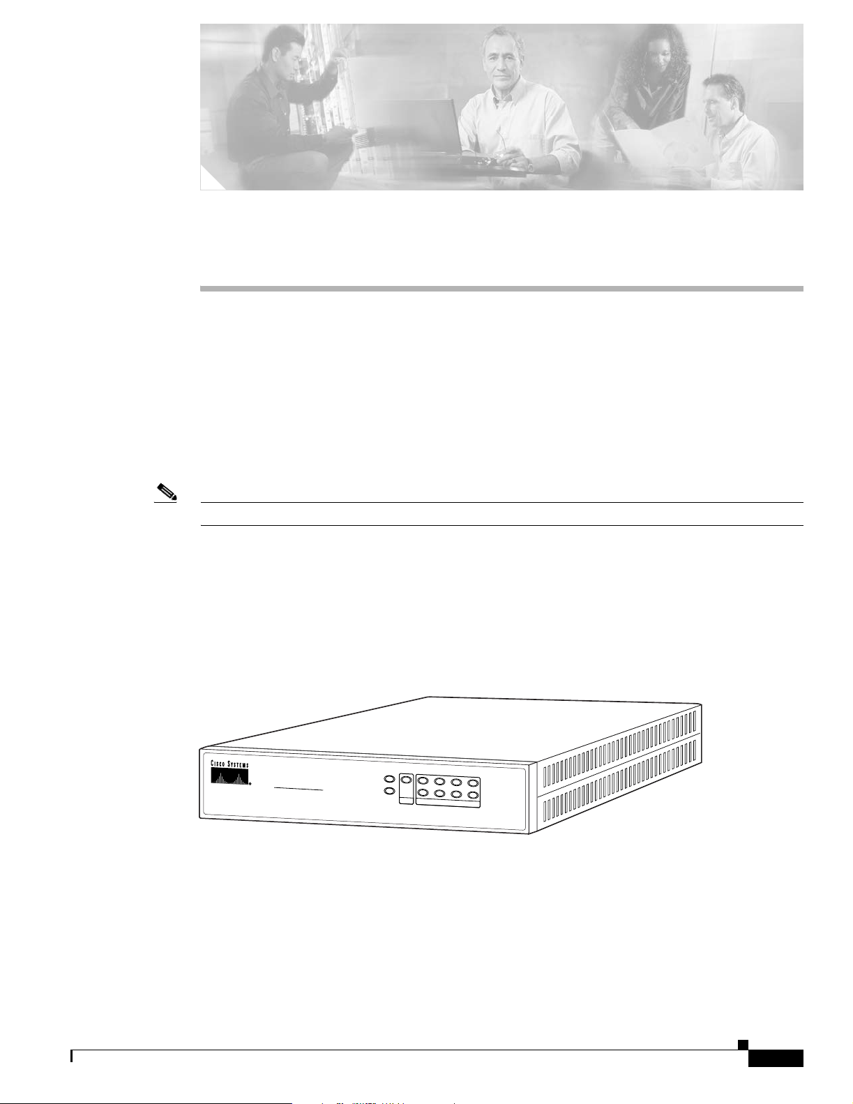
Figure 2-1 shows the front view of the PIX 501.
Figure 2-1 PIX 501 Front Panel
CISCO
®
PIX
501
FIREWALL
POWER
VPN TUNNEL
LINK/ACT
1234
100 MBPS
67848
78-15170-03
Cisco PIX Security Appliance Hardware Installation Guide
2-1
Page 28
PIX 501 Product Overview
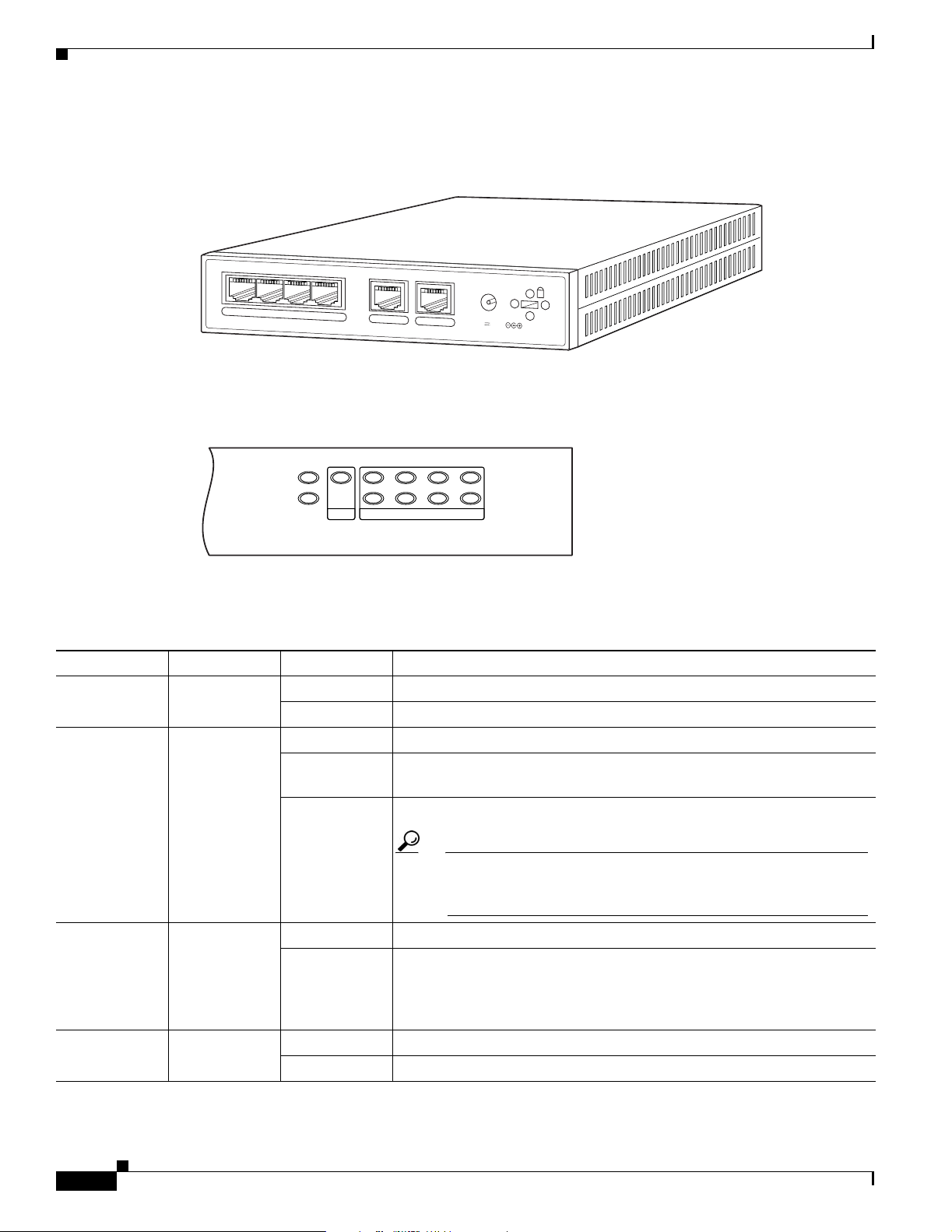
Figure 2-2 shows the rear view of the PIX 501.
Figure 2-2 PIX 501 Rear Panel
POWER
4
3
2
1
0
CONSOLE
3.3V 4.5A
Figure 2-3 shows the PIX 501 front panel LEDs.
Chapter 2 PIX 501
67849
POWER
VPN TUNNEL
12
3
LINK/ACT
100 MBPS
4
61926
Table 2 - 1 lists the states of the PIX 501 front panel LEDs.
Figure 2-3 PIX 501 Front Panel LEDs
Table 2-1 PIX 501 Front Panel LEDs
LED Color State Description
POWER Green On The device is powered on.
Off The device is powered off.
LINK/ACT Green Flashing Network activity, such as Internet access, is present.
On The correct cable is in use, and the connected equipment has power and
is operational.
Off No link is established.
Tip If the LINK/ACT LED does not light up, you might be using the
wrong type of cable. Try replacing the yellow, straight-through
Ethernet cable with the orange, crossover Ethernet cable.
VPN TUNNEL Green On One or more IKE/IPSec VPN tunnels are established.
Off One or more IKE/IPSec VPN tunnels are disabled. If the standard
configuration is not modified to support VPN tunnels, the LED does not
light up because it is disabled by default. Also, the LED does not light up
when PPTP/L2TP tunnels are established.
100 MBPS Green On The interface is enabled at 100 Mbps (autonegotiated).
Off The interface is enabled at 10 Mbps.
Cisco PIX Security Appliance Hardware Installation Guide
2-2
78-15170-03
Page 29
Chapter 2 PIX 501
Installing the PIX 501
Place the PIX 501 on a flat, stable surface. The PIX 501 is not rack mountable.
To install the PIX 501, perform the following steps:
Step 1 Connect Port 0, the outside Ethernet port, to the public network.
• Use the yellow Ethernet cable (72-1482-01) to connect the device to a switch or hub.
• Use the orange Ethernet cable (72-3515-01) to connect the device to a DSL modem, cable modem,
or router.
Step 2 Connect your PC or the other network devices to one of the four switched inside ports (numbered 1
through 4).
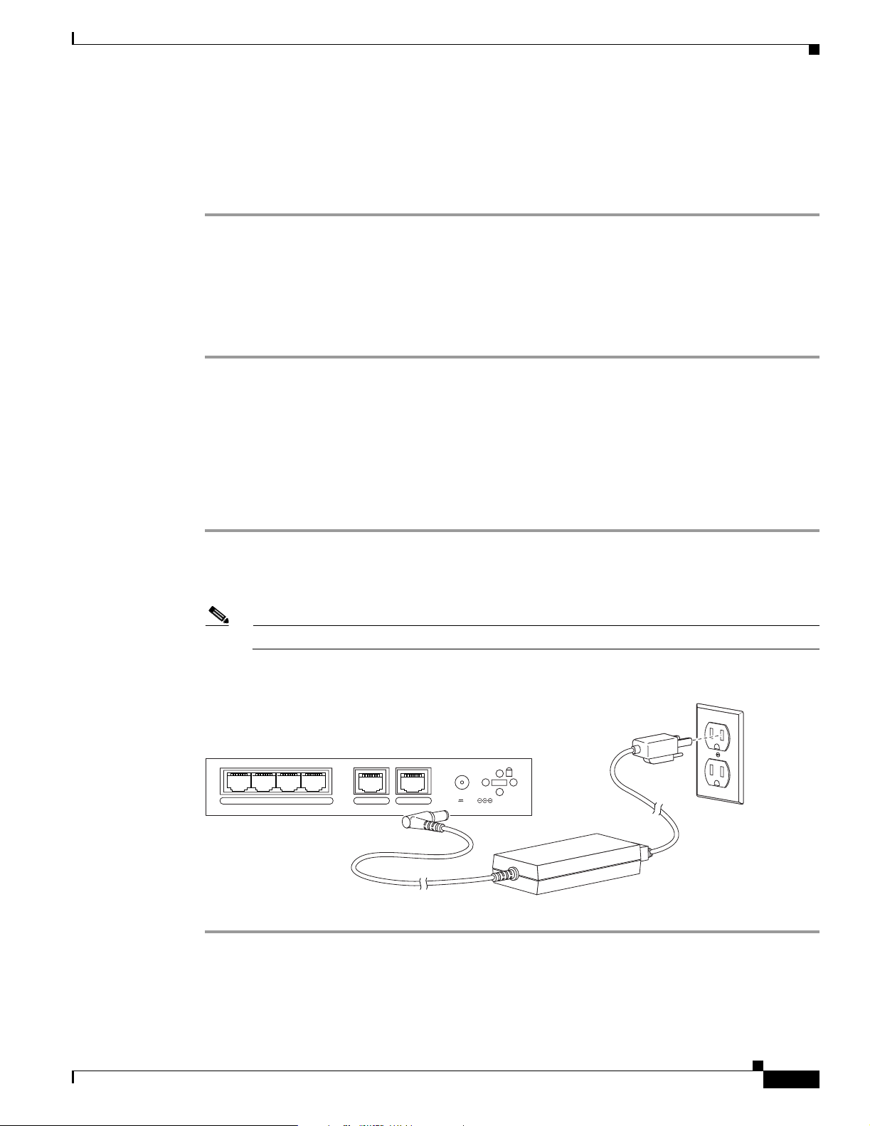
Connecting a Power Supply Module to the PIX 501
Installing the PIX 501
This section describes how to connect the power supply module to a PIX 501. Use this information in
conjunction with the Regulatory Compliance and Safety Information document.
To connect the power supply module to the PIX 501, perform the following steps:
Step 1 Connect the small, round connector of the power supply cable to the power connector on the rear panel
(see Figure 2-4).
Step 2 Connect the AC power connector of the power supply input cable to an electrical outlet.
Note The PIX 501 does not have a power switch. Completing Step 2 powers on the device.
Figure 2-4 Connecting the Power Supply Module to the PIX 501
POWER
43
2
1
0 CONSOLE
3.3V 4.5A
78-15170-03
Power supply
Cisco PIX Security Appliance Hardware Installation Guide
71534
2-3
Page 30
Removing and Replacing the PIX 501 Chassis Cover
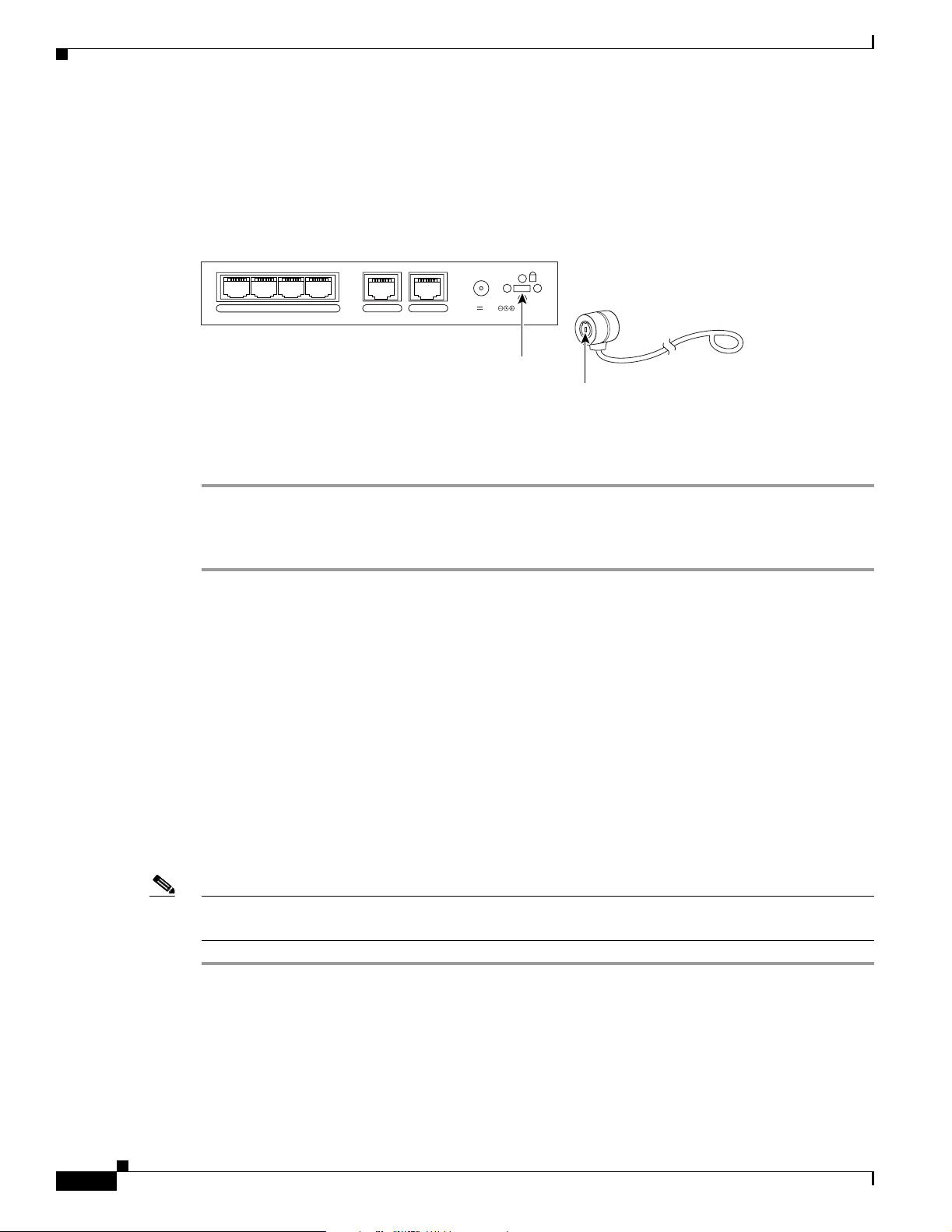
PIX 501 Cable Lock
The PIX 501 includes a slot that accepts standard desktop cable locks to provide physical security for
small portable equipment, such as laptop computers (see Figure 2-5).
Chapter 2 PIX 501
POWER
43
2
1
0 CONSOLE
3.3V 4.5A
Lock slot
Cable lock
(not included)
To install a security cable lock, perform the following steps:
Figure 2-5 PIX 501 Security Cable Lock
Step 1 Attach the cable lock to the lock slot on the back panel of the PIX 501.
Step 2 Follow the directions from the manufacturer for attaching the other end of the device for securing the
PIX 501.
Removing and Replacing the PIX 501 Chassis Cover
This section describes how to remove and replace the chassis cover from the PIX 501. This section
includes the following topics:
61929
• Removing the Chassis Cover, page 2-4
• Replacing the Chassis Cover, page 2-5
Removing the Chassis Cover
To remove the chassis cover, perform the following steps:
Note Removing the chassis cover does not affect your Cisco warranty. Upgrading the PIX security appliance
does not require any special tools and does not create any radio frequency leaks.
Step 1 Read the Regulatory Compliance and Safety Information document.
Step 2 Unplug the power cord from the power outlet to power off the security appliance.
Step 3 Disconnect the network interface cables.
Cisco PIX Security Appliance Hardware Installation Guide
2-4
78-15170-03
Page 31

Chapter 2 PIX 501
Step 4 Turn the unit upside down so that the top of the chassis is resting on a flat surface, and the front of the
Step 5 Unscrew the single screw located on the bottom of the chassis, centered under the front panel
Removing and Replacing the PIX 501 Chassis Cover
chassis is facing toward you.
(see Figure 2-6).
Figure 2-6 Removing PIX 501 Bottom Panel Screw
Step 6
POWER
VPN TUNNEL
LINK/ACT
1234
100 MBPS
119682
C
ISC
O
®
PIX
501
FIREWALL
Return the chassis to the upright position. Note that the chassis is comprised of two sections: top and
bottom (see Figure 2-7).
Figure 2-7 Sliding the Chassis Cover Off the Chassis
119683
CISCO
®
PIX
501
FIREWALL
POWER
VPN TUNNEL
LINK/ACT
1234
100 MBPS
Step 7
With the front panel facing you, slide the top section toward you, and then lift it up and off the bottom
section (see Figure 2-7).
Replacing the Chassis Cover
Caution Do not operate PIX security appliances without the chassis cover installed. The chassis cover protects
the internal components, prevents electrical shorts, and provides proper air-flow for cooling the
electronic components.
To replace the chassis cover, perform the following steps:
Step 1 Place the chassis on a secure surface with the front panel facing you.
Step 2 Hold the chassis cover so the tabs at the rear of the chassis cover are aligned with the chassis bottom.
78-15170-03
Cisco PIX Security Appliance Hardware Installation Guide
2-5
Page 32

Replacing a Lithium Battery
Step 3 Lower the front of the cover onto the chassis, making sure that the side tabs of the cover fit under the
side panels of the chassis.
Step 4 Slide the chassis cover toward the front, making sure that the cover tabs fit under the back panel, and the
back panel tabs fit under the chassis cover.
Step 5 Secure the chassis cover with the screw you set aside earlier.
Step 6 Reconnect the network interface cables.
Step 7 Place the PIX 501 on a flat, stable surface. The PIX 501 is not rack mountable.
Step 8 Reconnect the power cord to the power outlet to power on the security appliance.
Replacing a Lithium Battery
The PIX 501 has a lithium battery on the main circuit board (see Figure 2-8). This battery has an
operating life of about ten years. When the battery loses its charge, the PIX security appliance cannot
function. The lithium battery is a field-replaceable unit (FRU). You can use a standard 3V lithium battery
to replace the used battery.
Chapter 2 PIX 501
Figure 2-8 PIX 501 Lithium Battery Location
Front
Battery
119679
2-6
Warning
Cisco PIX Security Appliance Hardware Installation Guide
Danger of explosion exists if the lithium battery is incorrectly replaced. Replace only with the same
or equivalent type recommended by the manufacturer. Dispose of used batteries according to the
manufacturer's instructions.
78-15170-03
Page 33

Chapter 2 PIX 501
Step 1 Remove the chassis cover as described in the “Removing the Chassis Cover” section on page 2-4.
Step 2 Use a flathead screwdriver to slide the battery out of the metal clip on the circuit board (see Figure 2-8).
Step 3 Place the used battery aside and replace it with a new battery. Install the new battery writing side up.
Step 4 The battery snaps into place as you slide it into the battery slot.
Step 5 Replace the chassis cover as described in the “Replacing the Chassis Cover” section on page 2-5.
Replacing a Lithium Battery
To replace the lithium battery, perform the following steps:
78-15170-03
Cisco PIX Security Appliance Hardware Installation Guide
2-7
Page 34

Replacing a Lithium Battery
Chapter 2 PIX 501
2-8
Cisco PIX Security Appliance Hardware Installation Guide
78-15170-03
Page 35

CHAPTER
3
PIX 506/506E
This chapter describes how to install a PIX 506/506E, and includes the following sections:
• PIX 506/506E Product Overview, page 3-1
• Installing the PIX 506/506E, page 3-3
• Connecting a Power Supply Module to the PIX 506/506E, page 3-4
• Removing and Replacing the PIX 506/506E Chassis Cover, page 3-6
• Replacing a Lithium Battery, page 3-7
Note The PIX 506 and the PIX 506E are the same except the PIX 506E has a faster processor and a different
power supply.
The PIX 506 and the PIX 506E are not supported in software Version 7.0(1).
PIX 506/506E Product Overview
This section describes the PIX 506/506E front and rear panels and the panel LEDs.
Figure 3-1
Figure 3-1 PIX 506/506E Front Panel
POWER
shows the front view of the PIX 506/506E.
CISCO PIX 506E
ACT
NETWORK
FIREWALL
67945
78-15170-03
Cisco PIX Security Appliance Hardware Installation Guide
3-1
Page 36

PIX 506/506E Product Overview
Figure 3-2 shows the rear view of the PIX 506/506E.
Figure 3-2 PIX 506/506E Rear Panel
Figure 3-3 shows the PIX 506/506E front panel LEDs.
Figure 3-3 PIX 506/506E Front Panel LEDs
A
C
T
ETHERNET 1
Chapter 3 PIX 506/506E
67947
D
C
P
O
W
E
R
IN
P
U
L
I
N
K
A
C
T
L
I
N
K
ETHERNET 0
USB
CONSOLE
T
POWER ACT NETWORK
25735
Table 3 - 1 lists the states of the PIX 506/506E front panel LEDs.
Table 3-1 PIX 506/506E Front Panel LEDs
LED Color State Description
POWER Green On The unit has power.
ACT Green Flashing Active indicator—On when the software image has been
loaded on the security appliance.
NETWORK Green Flashing On when at least one network interface is passing traffic.
3-2
Cisco PIX Security Appliance Hardware Installation Guide
78-15170-03
Page 37

Chapter 3 PIX 506/506E
Installing the PIX 506/506E
Figure 3-4 shows the PIX 506/506E rear panel LEDs.
Figure 3-4 PIX 506/506E Rear Panel LEDs
ACT(ivity)
LED
ACT
E
T
H
10BaseT
(RJ-45)
E
ACT(ivity)
LED
LINK
LED
LINK
R
N
E
T
1
ACT
E
T
H
E
R
N
E
10BaseT
(RJ-45)
LINK
LED
LINK
T
0
U
S
B
USB
port
Power switch
DC
POWER
INPUT
C
O
N
S
O
L
E
38852
Console
port (RJ-45)
Table 3 - 2 lists the states of the PIX 506/506E rear panel LEDs.
Table 3-2 PIX 506/506E Rear Panel LEDs
LED Color State Description
ACT Green On Shows network activity.
LINK Green On Shows that data is passing on the network to which the
connector is attached.
The USB port at the left of the Console port is not used.
Installing the PIX 506/506E
Place the PIX 506/506E on a flat, stable surface. The PIX 506/506E is not rack mountable.
To install the PIX 506/506E, perform the following steps:
Step 1 Connect the cable so that you have either a DB-9 or DB-25 connector on one end as required by the serial
port for your computer, and the other end is the RJ-45 connector.
Note Use the RJ-45 Console port to connect a computer to enter configuration commands. Locate the
serial cable from the accessory kit. The serial cable assembly consists of a null modem cable
with RJ-45 connectors, and one DB-9 connector and one DB-25 connector.
78-15170-03
Cisco PIX Security Appliance Hardware Installation Guide
3-3
Page 38

Connecting a Power Supply Module to the PIX 506/506E
Step 2 Connect the RJ-45 connector to the PIX 506/506E and connect the other end to the serial port connector
on your computer (see Figure 3-7).
Figure 3-5 PIX 506/506E Serial Console Cable
ACT
LINK
ACT
E
T
H
E
R
N
E
T 1
E
Chapter 3 PIX 506/506E
DC
POWER
INPUT
LINK
T
H
E
R
N
E
T
0
U
S
B
C
O
N
S
O
L
E
Console
port (RJ-45)
Computer serial port
DB-9 or DB-25
RJ-45 to
DB-9 or DB-25
serial cable
(null-modem)
Step 3 Connect the inside network cable to the interface connector marked ETHERNET 0 or ETHERNET 1.
Note The inside or outside network connections can be made to either interface port on the
PIX 506/506E.
Step 4 Connect the outside network cable to the remaining Ethernet port.
Connecting a Power Supply Module to the PIX 506/506E
This section describes how to connect the power supply module to the PIX 506/506E. Use this
information in conjunction with the Regulatory Compliance and Safety Information document.
The PIX 506/506E uses an external AC to DC power supply. Power is supplied to the PIX 506/506E by
connecting the power supply to the back of the security appliance and connecting a separate AC power
cord to the power supply.
38853
3-4
Cisco PIX Security Appliance Hardware Installation Guide
78-15170-03
Page 39

Chapter 3 PIX 506/506E
Connecting a Power Supply Module to the PIX 506/506E
Figure 3-6 displays the cable connection from the power supply to the PIX 506, and displays the AC
power cord connector (at the opposite end of the power supply).
Figure 3-6 Connecting the Power Supply Module to the PIX 506 6-Pin Connector
DC
POWER
ACT
LINK
ACT
E
T
H
E
R
N
E
T
1
LINK
E
T
H
E
R
N
E
T
0
U
S
B
C
O
N
S
O
LE
INPUT
38854
Power supply
Figure 3-7 displays the cable connection from the power supply to the PIX 506E, and displays the AC
power cord connector (at the opposite end of the power supply).
Figure 3-7 Connecting the Power Supply Module to the PIX 506E 8-Pin Connector
DC
POWER
ACT
LINK
ACT
E
T
H
E
R
N
E
T
1
LINK
E
T
H
E
R
N
E
T
0
U
S
B
C
O
N
S
O
LE
Power supply
INPUT
67847
78-15170-03
To connect the power supply module, perform the following steps:
Step 1 Place the PIX 506/506E on a flat, stable surface. The PIX 506/506E is not rack mountable.
Step 2 Connect the power supply to the back of the PIX 506/506E. See Figure 3-6 for the PIX 506 and
Figure 3-7 for the PIX 506E.
Step 3 When you are ready to start the PIX 506/506E, power on the unit from the switch at the rear of the unit.
Cisco PIX Security Appliance Hardware Installation Guide
3-5
Page 40

Chapter 3 PIX 506/506E
Removing and Replacing the PIX 506/506E Chassis Cover
Removing and Replacing the PIX 506/506E Chassis Cover
This section describes how to remove and replace the chassis cover from the PIX 506/506E. This section
includes the following topics:
• Removing the Chassis Cover, page 3-6
• Replacing the Chassis Cover, page 3-7
Removing the Chassis Cover
To remove the chassis cover, perform the following steps:
Note Removing the chassis cover does not affect your Cisco warranty. Upgrading the PIX security appliance
does not require any special tools and does not create any radio frequency leaks.
Step 1 Read the Regulatory Compliance and Safety Information document.
Step 2 Power off the security appliance and unplug the power cord.
Warning
Before working on a system that has an On/Off switch, turn OFF the power and unplug the power cord.
Step 3 Disconnect the network interface cables.
Step 4 Remove the two screws from the back of the chassis (see Figure 3-8).
Figure 3-8 Removing PIX 506/506E Chassis Cover Screws
119681
D
C
P
O
W
E
R
IN
P
U
A
C
T
L
IN
K
A
C
T
L
IN
E
T
H
E
R
N
E
T
1
K
E
T
H
E
R
N
E
T
0
U
S
B
C
O
N
S
O
L
E
T
Step 5 With the rear panel facing you, slide the chassis cover back and then lift it up off the bottom section, as
shown in Figure 3-8.
3-6
Cisco PIX Security Appliance Hardware Installation Guide
78-15170-03
Page 41

Chapter 3 PIX 506/506E
Replacing the Chassis Cover
Caution Do not operate PIX security appliances without the chassis cover installed. The chassis cover protects
the internal components, prevents electrical shorts, and provides proper air-flow for cooling the
electronic components.
To replace the chassis cover, perform the following steps:
Step 1 Place the chassis on a secure surface with the front panel facing you.
Step 2 Hold the chassis cover so the tabs at the rear of the cover are aligned with the bottom of the chassis.
Step 3 Lower the front of the cover onto the chassis, making sure that the side tabs of the cover fit under the
side panels of the chassis.
Step 4 Slide the chassis cover toward the front, making sure that the cover tabs fit under the back panel, and the
back panel tabs fit under the chassis cover.
Step 5 Secure the chassis cover with the screws you set aside earlier.
Step 6 Reconnect the network interface cables.
Replacing a Lithium Battery
Step 7 Place the PIX 506/506E on a flat, stable surface. The PIX 506/506E is not rack mountable..
Step 8 Reconnect the power cord and power on the security appliance.
Replacing a Lithium Battery
The PIX 506/506E has a lithium battery on its main circuit board (see Figure 3-9). This battery has an
operating life of about ten years. When the battery loses its charge, the PIX security appliance cannot
function. The battery is a field-replaceable unit (FRU). You can use a standard 3V lithium battery to
replace the used battery.
78-15170-03
Cisco PIX Security Appliance Hardware Installation Guide
3-7
Page 42

Replacing a Lithium Battery
Figure 3-9 PIX 506/506E Lithium Battery Location
Chapter 3 PIX 506/506E
Battery
Front
119680
Warning
Danger of explosion exists if the lithium battery is incorrectly replaced. Replace only with the same
or equivalent type recommended by the manufacturer. Dispose of used batteries according to the
manufacturer's instructions.
To replace the lithium battery, perform the following steps:
Step 1 Remove the chassis cover as described in the “Removing the Chassis Cover” section on page 3-6.
Step 2 Use a flathead screwdriver to slide the battery out of the metal clip on the circuit board (see Figure 3-9).
Step 3 Place the used battery aside and replace it with a new battery. Install the new battery writing side up.
Step 4 The battery snaps into place as you slide it into the battery slot.
Step 5 Replace the chassis cover by lining up the cover tabs with the bottom panel tabs, and sliding the chassis
cover back into the side and front panel slots on the chassis.
Step 6 Replace the chassis cover as described in the “Replacing the Chassis Cover” section on page 3-7.
3-8
Cisco PIX Security Appliance Hardware Installation Guide
78-15170-03
Page 43

CHAPTER
PIX 515/515E
This chapter describes how to install the PIX 515/515E, and includes the following sections:
• PIX 515/515E Product Overview, page 4-1
• Installing the PIX 515/515E, page 4-3
• PIX 515/515E Feature Licenses, page 4-8
• Installing Failover, page 4-9
• Installing LAN-Based Failover, page 4-12
• Removing and Replacing the PIX 515/515E Chassis Cover, page 4-13
• Replacing a Lithium Battery, page 4-15
• Installing a Memory Upgrade, page 4-16
• Installing a Circuit Board in the PIX 515/515E, page 4-19
• Installing the PIX 515/515E DC Model, page 4-23
4
Note The PIX 515 and the PIX 515E are the same except that the PIX 515E has a faster processor.
PIX 515/515E Product Overview
This section describes the front and rear panels and the panel LEDs.
Figure 4-1 shows the front view of the chassis.
Figure 4-1 PIX 515/515E Front Panel
P
O
W
E
R
A
C
T
N
E
T
W
O
R
K
PIX Firewall
SERIES
67851
78-15170-03
Cisco PIX Security Appliance Hardware Installation Guide
4-1
Page 44

PIX 515/515E Product Overview
Figure 4-2 shows the rear view of the chassis.
Figure 4-2 PIX 515/515E Rear Panel
Figure 4-3 shows the front panel LEDs.
Figure 4-3 PIX 515/515E Front Panel LEDs
POWER ACT NETWORK
Chapter 4 PIX 515/515E
D
O
N
O
T
I
N
S
T
A
L
L
I
N
T
E
R
F
A
C
E
C
A
R
D
S
W
I
T
H
P
O
W
E
R
A
P
P
L
I
E
D
1
0
0
M
L
b
in
p
s
k
F
D
X
1
0
0
M
b
p
s
L
in
k
1
0
/
1
0
0
E
T
H
E
F
R
N
E
T
0
/
0
1
0
/1
0
0
E
T
H
E
R
N
E
T
0
PIX-515
F
A
IL
O
V
E
R
D
X
/0
C
O
N
S
O
L
E
67850
25735
Table 4 - 1 lists the states of the front panel LEDs.
Table 4-1 PIX 515/515E Front Panel LEDs
LED Color State Description
POWER Green On On when the unit has power.
ACT Green On On when the unit is the active failover unit. If failover is present,
the light is on when the unit is the active unit.
Off Off when the unit is in standby mode. If failover is not enabled, this
light is off.
NETWORK Green Flashing On when at least one network interface is passing traffic.
4-2
Cisco PIX Security Appliance Hardware Installation Guide
78-15170-03
Page 45

Chapter 4 PIX 515/515E
Installing the PIX 515/515E
Figure 4-4 shows the rear panel LEDs.
Figure 4-4 PIX 515/515E Rear Panel
0
E
T
H
E
R
100 Mbps
LED
LINK
LED
LINK
N
E
T 1
100 Mbps
ACT
LED
LINK
LED
ACT
10
LINK
/1
0
0 E
TH
E
R
N
E
T
0
10/100BaseTX
ETHERNET 0
(RJ-45)
USB
U
S
B
C
O
N
Console
port (RJ-45)
FAILOVER
S
O
LE
PIX-515
96905
Power switch
100 Mbps
LED
ACT
LED
DO NOT INSTALL INTERFACE
CARDS WITH POWER APPLIED
100 Mbps
ACT
1
0/10
10/100BaseTX
ETHERNET 1
(RJ-45)
Table 4 - 2 lists the states of the rear panel LEDs.
Table 4-2 PIX 515/515E Rear Panel LEDs
LED Color Status Description
100 Mbps Green On 100 megabits per second 100BaseTX communication. If the light is
off, that port is using 10 megabits per second data exchange.
ACT Green Flashing Shows that data is passing on the network to which the connector is
attached.
LINK Green On Shows that the connection uses full duplex data exchange where
data is transmitted and received simultaneously.
Off If this light is off, half duplex is in effect.
The inside or outside network connections can be made to any available interface port on the
PIX 515/515E. If you are only using the ETHERNET 0 and ETHERNET 1 ports, connect the inside
network cable to the interface connector marked ETHERNET 0 or ETHERNET 1. Connect the outside
network cable to the remaining Ethernet port.
The USB port to the left of the Console port is not used. The detachable plate above the ETHERNET 1
connector is also not used.
Installing the PIX 515/515E
This section contains the following topics:
• Surface Mounting the PIX 515/515E, page 4-4
• Removing and Replacing the PIX 515/515E Chassis Cover, page 4-13
• Vertical Mounting the PIX 515/515E, page 4-5
• Installing a Circuit Board in the PIX 515/515E, page 4-19
78-15170-03
Cisco PIX Security Appliance Hardware Installation Guide
4-3
Page 46

Installing the PIX 515/515E
Surface Mounting the PIX 515/515E
To surface mount the chassis, perform the following steps:
Step 1 Locate the rubber feet on the black adhesive strip that shipped with the chassis.
Step 2 Place the chassis upside down on a smooth, flat surface.
Step 3 Peel off the rubber feet from the black adhesive strip and place them adhesive-side down onto the five round,
recessed areas on the bottom of the chassis, as shown in Figure 4-5.
Step 4 Place the security appliance right-side up on a flat, smooth, secure surface.
Note The fan is not blocked by the device below if you surface mount the chassis on top of each other, the air
is sucked in from the back and side vents and exhausted out with the help of the fan through the bottom
of the chassis and then directed out the side of the channel by the channel feature on the bottom of the
chassis.
Figure 4-5 Attaching the Rubber Feet to the PIX 515/515E
Chapter 4 PIX 515/515E
Fan
24301
Unused
4-4
Cisco PIX Security Appliance Hardware Installation Guide
78-15170-03
Page 47

Chapter 4 PIX 515/515E
Rack Mounting the PIX 515/515E
Observe the following before installing the chassis into an equipment rack:
• To install optional circuit boards or memory, install the brackets on the unit for rack mounting, but
do not put the chassis in the equipment rack before installing the new boards. You must remove the
chassis cover to install or remove a circuit board. Refer to the “Removing and Replacing the
PIX 515/515E Chassis Cover” section on page 4-13 for information.
–
For more information on installing a circuit board, refer to the “Installing a Circuit Board in the
PIX 515/515E” section on page 4-19.
–
For more information on installing additional memory, refer to the “Installing a Memory
Upgrade” section on page 4-16.
Note The fan is not blocked by the device below if you mount the chassis on top of each other, the air is sucked
in from the back and side vents and exhausted out with the help of the fan through the bottom of the
chassis and then directed out the side of the channel by the channel feature on the bottom of the chassis.
To install the chassis in a rack, perform the following steps:
Installing the PIX 515/515E
Step 1 Attach the bracket to the chassis using the supplied screws. You can attach the brackets to the holes near
the front of the chassis.
Step 2 Attach the chassis to the equipment rack.
Vertical Mounting the PIX 515/515E
To mount the chassis vertically, attach the brackets to the side of the unit and mount the unit vertically
as shown in Figure 4-6.
Figure 4-6 Installing the PIX 515/515E Vertically
PIX-515
R
E
V
O
L
I
A
F
E
L
O
S
N
O
C
0
X
/
D
F
0
T
E
N
R
E
H
T
E
0
0
1
k
/
0
in
L
1
s
p
b
M
0
0
1
X
0
D
/
F
0
T
E
N
R
E
H
T
D
E
E
IE
C
L
0
A
P
0
F
k
P
R
/1
in
E
A
0
L
T
R
1
s
E
p
IN
b
W
L
L
M
O
A
0
P
T
0
1
H
S
IT
IN
T
W
O
S
D
N
R
O
A
D
C
78-15170-03
24303
Cisco PIX Security Appliance Hardware Installation Guide
4-5
Page 48

Installing the PIX 515/515E
F
A
I
L
O
V
E
R
1
0
0
M
b
p
s
A
C
T
1
0
0
M
b
p
s
A
C
T
L
IN
K
L
IN
K
P
I
X
-
5
2
5
1
0
/1
0
0
E
T
H
E
R
N
E
T
1
1
0
/1
0
0
E
T
H
E
R
N
E
T
0
U
S
B
C
O
N
S
O
L
E
Installing the PIX 515/515E
To install the PIX 515/515E, perform the following steps:
Step 1 Connect the cable as shown in Figure 4-7 so that you have either a DB-9 or DB-25 connector on one end
as required by the serial port for your computer, and the other end is the RJ-45 connector.
Note Use the Console port to connect to a computer to enter configuration commands. Locate the
serial cable from the accessory kit. The serial cable assembly consists of a null modem cable
with RJ-45 connectors, and one DB-9 connector and a DB-25 connector.
Step 2 Connect the RJ-45 connector to the PIX 515/515E Console port and connect the other end to the serial
port connector on your computer.
Figure 4-7 PIX 515/515E Serial Console Cable
Chapter 4 PIX 515/515E
Console
port (RJ-45)
RJ-45 to
DB-9 or DB-25
serial cable
(null-modem)
PC terminal adapter DB-9
104944
Note If your unit has a four-port Ethernet circuit board already installed, refer to Figure 4-8. (The
four-port Ethernet circuit board requires the PIX-515/515E-UR license to be accessed.) If it has
one or two single-port Ethernet circuit boards, refer to Figure 4-9. If you need to install an
optional circuit board, refer to the “Removing and Replacing the PIX 515/515E Chassis Cover”
section on page 4-13 for more information.
Cisco PIX Security Appliance Hardware Installation Guide
4-6
78-15170-03
Page 49

Chapter 4 PIX 515/515E
Figure 4-8 Four-Port Ethernet Connectors in the PIX 515/515E
Ethernet 5
Ethernet 3
D
O
N
O
T
I
N
S
T
A
L
L
I
N
T
E
R
F
A
C
E
C
A
R
D
S
W
I
T
H
P
O
W
E
R
A
P
P
L
I
E
D
1
0
0
M
L
b
in
p
s
k
F
D
X
1
0
0
M
b
p
s
L
in
k
1
0
/
1
0
0
E
T
H
E
R
N
E
T
1
1
0
/1
0
0
E
T
H
E
R
N
E
T
PIX-515
F
A
IL
O
V
E
R
F
D
X
0
C
O
N
S
O
L
E
Ethernet 2
Ethernet 4
Ethernet 1
Ethernet 0
Installing the PIX 515/515E
25733
Step 3
Connect the inside, outside, or perimeter network cables to the interface ports. Starting from the top left
the connectors are Ethernet 2, Ethernet 3, Ethernet 4, and Ethernet 5. The maximum number of allowed
interfaces is 6.
Note Do not add a single-port circuit board in the extra slot below the four-port circuit board.
Figure 4-9 Two Single-Port Ethernet Connectors in the PIX 515/515E
Ethernet 2
D
O
N
O
T
I
N
S
T
A
L
L
I
N
T
E
R
F
A
C
E
C
A
R
D
S
W
I
T
H
P
O
W
E
R
A
P
P
L
I
E
Ethernet 3
D
1
0
0
M
L
b
in
p
s
k
F
D
X
1
0
1
0
/
1
0
0
E
T
H
E
R
N
E
T
1
Ethernet 1
PIX-515
F
A
IL
O
0
M
b
p
s
L
in
k
1
0
/
1
0
0
E
T
H
E
V
E
R
F
D
X
R
N
E
T
0
C
O
N
S
O
L
E
25734
Ethernet 0
Note As shown in Figure 4-9, if your unit has one or two single-port Ethernet circuit boards installed
in the auxiliary assembly on the left of the unit at the rear, the circuit boards are numbered top
to bottom so that the top circuit board is Ethernet 2 and the bottom circuit board is Ethernet 3.
(Additional Ethernet circuit boards require the PIX-515/PIX 515E-UR license to be accessed.)
78-15170-03
If you have a second PIX security appliance to use as a failover unit, install the failover feature and cable
as described in the “Installing Failover” section on page 4-9.
Note Do not power on the failover units until the active unit has been configured.
Step 4 Power on the unit from the switch at the rear to start the PIX 515/515E.
Cisco PIX Security Appliance Hardware Installation Guide
4-7
Page 50

PIX 515/515E Feature Licenses
Table 4 - 3 lists the states of the LEDs on the four-port Ethernet circuit boards available for the
PIX-515/515E.
Table 4-3 Status Lights on Four-Port Ethernet Circuit Boards
Board Model LED position Color Status Description
PIX-4FE left Green On Link enabled.
right Green Flashing Link activity.
PIX-4FE-66 left Green Flashing Link activity.
right Green On 100 MB link enabled.
PIX 515/515E Feature Licenses
If you have the PIX-515/515E-UR unrestricted feature license, the following options are available:
• If you have a second PIX 515/515E to use as a failover unit, install the failover feature and cable as
described in the “Installing Failover” section on page 4-9.
Chapter 4 PIX 515/515E
Off 10 MB link enabled.
• If needed, install the PIX security appliance syslog server as described in the logging command page
in the command reference online at:
http://cisco.com/en/US/products/sw/secursw/ps2120/prod_command_reference_list.html
• Refer to the “Removing and Replacing the PIX 515/515E Chassis Cover” section on page 4-13, for
information about how to remove and replace the chassis cover if you need to install optional circuit
boards.
Note It is very important to remove the chassis cover before installing circuit boards in the PIX 515/515E.
Even though it appears possible to add or remove circuit boards from the back panel, removing the
chassis cover greatly simplifies the process.
• If you need to install additional memory, refer to the “Installing a Memory Upgrade” section on
page 4-16.
Note If, for any reason, you choose to downgrade to any software version, note that you must use the clear
flashfs command before doing so. A new section is added to Flash memory that must be cleared before
downgrading.
For information on upgrading feature licenses or downloading the latest software versions, refer to the
the configuration guide online at:
http://www.cisco.com/en/US/products/sw/secursw/ps2120/prod_configuration_guides_list.html
This section includes the following topics:
4-8
• VPN Accelerator Card, page 4-9
• VPN Accelerator Card+, page 4-9
Cisco PIX Security Appliance Hardware Installation Guide
78-15170-03
Page 51

Chapter 4 PIX 515/515E
VPN Accelerator Card
The VPN Accelerator Card (VAC) for the Cisco PIX security appliance series is a card that provides
high-performance, tunneling and encryption services suitable for site-to-site and remote access applications.
The VAC is integrated with PIX 515 unrestricted (UR) and failover (FO) bundles. You can also purchase the
VAC as a spare for use with PIX 515s that have a restricted (R) license.
VPN Accelerator Card+
The VAC+ is a 64-bit/66 MHz PCI card that provides faster tunneling and encryption services for Virtual
Private Network (VPN) remote access, and site-to-site intranet and extranet applications, than the VAC.
Each VAC+ occupies a single PCI slot in the system. The VAC+ is supported on any chassis that runs
Version 6.3 software or later, has an appropriate license to run VPN software, and at least one PCI slot
available. While the VAC continues to be supported in Version 6.3, if both types of cards, the VAC and
the VAC+, are installed in a system running Version 6.3, the VAC card is ignored. The VAC+ runs at both
32-bit/33 MHz and 64-bit/66 MHz, and does not slow down the bus when other 66 MHz cards are
installed. We strongly recommend that you install the VAC+ in a 64bit/66 MHz slot. Performance is degraded
if this recommendation is not followed.
Installing Failover
The VAC+ driver supports the following:
• 3DES, DES, AES, SHA1, MD5 for (IPSec) ESP protocol (For AES, only the CBC mode and key
sizes of 128, 192, and 256 bits are supported).
• SHA1, MD5 for the (IPSec) AH protocol.
• Load sharing ESP and AH activity between up to three VAC+.
• Diffie-Hellman public key and shared secret generation.
• Any other crypto-related activity uses a software implementation.
Installing Failover
To install a failover connection, perform the following steps:
Step 1 Power off both the primary and secondary units.
Note Both PIX security appliances must have the same model number, have at least as much RAM,
have the same Flash memory size, and be running the same software version. Note that the
PIX-4FE and PIX-4FE-66 cards are considered equivalent and interchangeable. You can install
a PIX-4FE in the primary unit and a PIX-4FE-66 in the secondary unit, as long as you install
them in the same slot number of each chassis. For example, if you install a PIX-4FE in Slot 1 of
the primary unit, you must also install the PIX-4FE-66 in Slot 1 of the secondary unit.
78-15170-03
Step 2 Locate the failover cable (shown in Figure 4-10). The cable is labeled “Primary” on one end and
“Secondary” on the other.
Install the cable for the PIX 515/515E as shown in Figure 4-10.
Cisco PIX Security Appliance Hardware Installation Guide
4-9
Page 52

Installing Failover
Figure 4-10 PIX 515/515E Failover Cable Connection
FAILOVER
Primary end
Y
R
A
M
I
R
P
Secondary end
24297
Y
R
A
D
N
O
C
E
S
Chapter 4 PIX 515/515E
FAILOVER
Note You can connect the PIX 515 to the PIX 515, but you cannot connect the PIX 515 to the
PIX 515E or vice versa. Both units must be identical.
Step 3 Connect the Primary end of the failover cable to the first PIX security appliance; that is, the one you have
already configured.
Step 4 Connect the Secondary end of the failover cable to the standby unit.
Step 5 Connect a power cord to the power connector on the rear panel of each unit, and the other end of each
power cord to (preferably separate) power outlets.
Step 6 If you are using Stateful Failover, use one of the following types of connections, that is appropriate for
your system, between the dedicated interfaces on the PIX security appliance:
• Category 5 crossover cable directly connecting the primary unit to the secondary unit
• 100BaseTX half-duplex hub using Straight-through Category 5 cables
• 100BaseTX full duplex on a dedicated switch or dedicated VLAN of a switch
4-10
Cisco PIX Security Appliance Hardware Installation Guide
78-15170-03
Page 53

Chapter 4 PIX 515/515E
Figure 4-11 shows an example of a minimally configured PIX 515/515E with only the two interfaces on
the motherboard used for network traffic.
Figure 4-11 Failover Connections
Installing Failover
Stateful Failover
dedicated interface
cable
Outside switch
Internet
Note All enabled interfaces must be connected between the active and standby units. Only configure the active
Power
D
O
N
O
T
I
N
S
T
A
L
L
I
N
T
E
R
F
A
C
E
C
A
R
D
S
W
I
T
H
P
O
W
E
R
A
P
P
L
I
E
D
1
0
0
M
b
L
p
in
s
k
1
0
/
1
0
0
E
T
H
E
R
PIX 515
Primary unit
F
D
X
1
0
0
M
b
p
s
L
in
k
F
D
X
N
E
T
1
1
0
/
1
0
0
E
T
H
E
R
N
E
T
0
C
O
N
S
O
L
PIX 515
Standby unit
D
O
N
O
T
I
N
S
T
A
L
L
I
N
T
E
R
F
A
C
PIX-515
F
A
I
L
O
V
E
R
E
E
C
A
R
D
S
W
I
T
H
P
O
W
E
R
A
P
P
L
I
E
D
1
0
0
M
L
b
i
p
n
s
k
F
D
X
1
0
0
1
0
/
1
0
0
E
T
H
E
R
N
E
T
1
PIX-515
F
A
IL
O
V
E
M
R
b
p
s
L
in
k
F
D
X
1
0
/
1
0
0
E
T
H
E
R
N
E
T
0
C
O
N
S
O
L
E
UPS
(not supplied)
Failover
serial cable
Inside switch
Inside
network
unit. On the PIX 515/515E, the active unit is indicated by the ACT LED on the front panel. (See
Figure 4-3.)
27883
78-15170-03
Caution Do not turn the power on until the units are connected and the primary unit is configured completely.
Step 7 Use the power switch at the back of the units to power on the primary unit and then power on the standby
unit.
Within a few seconds, the active unit automatically downloads its configuration to the standby unit.
If the primary unit fails, the secondary unit automatically becomes active.
Cisco PIX Security Appliance Hardware Installation Guide
4-11
Page 54

Installing LAN-Based Failover
Installing LAN-Based Failover
LAN-based failover supports failover between two units connected over a dedicated Ethernet interface.
LAN-based failover eliminates the need for a special failover cable and overcomes the distance
limitations imposed by the failover cable.
Note Both chassis must be the same model number, have the same amount of RAM, Flash memory, number
and type of interfaces, and be running the same software version.
To set up a LAN-based failover connection, perform the following steps:
Step 1 Disconnect both PIX security appliances, so that there is no traffic flow between them. If the failover
cable is connected to the PIX security appliance, disconnect it.
Step 2 Configure the PIX security appliances for LAN-based failover. Refer to the chapter on configuring
LAN-based failover in the configuration guide online at:
http://www.cisco.com/en/US/products/sw/secursw/ps2120/prod_configuration_guides_list.html
Chapter 4 PIX 515/515E
Step 3 Power off both units.
Step 4 Connect the LAN failover interfaces to the dedicated switch/hub, as shown in Figure 4-12.
Note A dedicated LAN interface and a dedicated switch (or VLAN) is required to implement
LAN-based failover. You cannot use a crossover Ethernet cable to connect the two PIX security
appliances.
Figure 4-12 LAN-Based Failover Connections
Dedicated Ethernet
interface
PIX 515
D
O
N
O
T
I
N
S
T
A
L
L
I
N
T
E
R
F
A
C
E
C
A
R
D
S
W
I
T
H
P
O
W
E
R
A
P
P
L
I
E
D
1
0
0
M
b
L
p
in
s
k
F
D
X
1
0
0
M
b
p
s
L
in
k
F
D
1
0
/
1
0
0
E
T
H
E
R
N
E
T
1
1
0
/
1
0
0
E
T
H
E
R
N
E
T
0
Hub/switch
D
O
N
O
PIX-515
F
A
IL
O
V
E
R
X
C
O
N
S
O
L
E
T
C
A
R
D
S
Dedicated Ethernet
interface
PIX 515
I
N
S
T
A
L
L
I
N
T
E
R
F
A
C
E
W
I
T
H
P
O
W
E
R
A
P
P
L
I
E
D
1
0
0
M
L
b
in
p
s
k
F
D
X
1
0
0
M
1
0
/
1
0
0
E
T
H
E
R
N
E
T
1
PIX-515
F
A
IL
O
V
E
R
b
p
s
L
in
k
F
D
X
1
0
/
1
0
0
E
T
H
E
R
N
E
T
0
C
O
N
S
O
L
E
87313
4-12
Cisco PIX Security Appliance Hardware Installation Guide
78-15170-03
Page 55

Chapter 4 PIX 515/515E
Removing and Replacing the PIX 515/515E Chassis Cover
Step 5 If you are using Stateful Failover, use one of the following types of connections, that is appropriate for
your system, between the dedicated interfaces on the PIX security appliance:
• 100BaseTX full duplex on a dedicated switch or dedicated VLAN of a switch
• 1000BaseTX full duplex on a dedicated switch or dedicated VLAN of a switch
Caution Do not turn the power on until the units are connected and the primary unit is configured completely.
Step 6 Power the primary unit on first, then power on the secondary unit. Within a few seconds, the active unit
automatically downloads its configuration to the standby unit.
If the primary unit fails, the secondary unit automatically becomes active.
Removing and Replacing the PIX 515/515E Chassis Cover
This section describes how to remove and replace the chassis cover from the PIX 515/515E. This section
includes the following topics:
• Removing the Chassis Cover, page 4-13
• Replacing the Chassis Cover, page 4-15
Removing the Chassis Cover
To remove the chassis cover, perform the following steps:
Note Removing the chassis cover does not affect your Cisco warranty. Upgrading the PIX security appliance
does not require any special tools and does not create any radio frequency leaks.
Step 1 Read the Regulatory Compliance and Safety Information document.
Step 2 Unplug the power cord from the power outlet. Ensure that the PIX 515/515E is powered off. Once the
upgrade is complete, you can safely reconnect the power cord.
Warning
Before working on a system that has an On/Off switch, turn OFF the power and unplug the power cord.
78-15170-03
Cisco PIX Security Appliance Hardware Installation Guide
4-13
Page 56

Removing and Replacing the PIX 515/515E Chassis Cover
Step 3 Remove the screws from the front of the chassis on the PIX 515/515E (Figure 4-13).
Chapter 4 PIX 515/515E
Top panel screws (4)
D
O
N
O
T
I
N
S
T
A
L
L
I
N
T
E
R
F
A
C
E
C
A
R
D
S
W
I
T
H
P
O
W
E
R
A
P
P
L
I
E
D
1
0
0
M
L
b
in
p
s
k
F
D
X
1
0
0
M
b
p
s
L
in
k
1
0
/
1
0
0
E
T
H
E
R
N
E
T
0
/
0
1
0
/1
0
0
E
T
H
E
R
N
E
T
PIX-515
F
A
IL
O
V
E
R
F
D
X
0
/0
C
O
N
S
O
L
E
24305
Step 4 With the front of the unit facing you, push the chassis cover back by about one inch as shown in
Figure 4-14.
Figure 4-14 Pushing Back the Chassis Cover
PIX Firewall
SERIES
P
O
W
ACT NETWORK
E
Figure 4-13 Removing PIX 515/515E Chassis Cover Screws
R
24285
Step 5 Pull the chassis cover up as shown in Figure 4-15. Put the chassis cover in a safe place.
Figure 4-15 Pull the Chassis Cover up to Remove
PIX Firewall
SERIES
P
O
W
ACT NETWORK
E
R
24286
4-14
Cisco PIX Security Appliance Hardware Installation Guide
78-15170-03
Page 57

Chapter 4 PIX 515/515E
Replacing the Chassis Cover
Caution Do not operate the PIX security appliance without the chassis cover installed. The chassis cover protects
the internal components, prevents electrical shorts, and provides proper air-flow for cooling the
electronic components.
To replace the chassis cover, perform the following steps:
Step 1 Place the chassis on a secure surface with the front panel facing you.
Step 2 Hold the chassis cover so the tabs at the rear of the chassis cover are aligned with the chassis bottom.
Step 3 Lower the front of the chassis cover onto the chassis, making sure that the chassis cover side tabs fit
under the chassis side panels.
Step 4 Slide the chassis cover toward the front, making sure that the chassis cover tabs fit under the chassis back
panel, and the back panel tabs fit under the chassis cover.
Step 5 Fasten the chassis cover with the screws you set aside earlier.
Step 6 Reinstall the chassis on a rack, wall, desktop, or table.
Replacing a Lithium Battery
Step 7 Reinstall network interface cables.
Replacing a Lithium Battery
The PIX security appliance has a lithium battery on its main circuit board. This battery has an operating
life of about ten years. When the battery loses its charge, the PIX security appliance cannot function.
The lithium battery is not a field-replacable unit (FRU) for the PIX 515/515E. Contact Cisco TAC to
replace the battery.
Note Do not attempt to replace this battery yourself.
Warning
Danger of explosion exists if the lithium battery is incorrectly replaced. Replace only with the same
or equivalent type recommended by the manufacturer. Dispose of used batteries according to the
manufacturer's instructions.
78-15170-03
Cisco PIX Security Appliance Hardware Installation Guide
4-15
Page 58

Installing a Memory Upgrade
Installing a Memory Upgrade
Observe the following warnings, cautions, and notes when installing additional system memory.
The following statement applies to DC models:
Chapter 4 PIX 515/515E
Warning
Warning
Caution If you remove the chassis cover, always reinstall the cover. Running the PIX security appliance without the
Before performing any of the following procedures, ensure that power is removed from the DC circuit.
To ensure that all power is OFF, locate the circuit breaker on the panel board that services the DC
circuit, switch the circuit breaker to the OFF position, and tape the switch handle of the circuit
breaker in the OFF position.
The following statements apply to both AC and DC models:
Before working on a system that has an On/Off switch, turn OFF the power and unplug the power cord.
chassis cover causes the system to overheat and and might damage the electrical components.
Memory Installation Steps
Depending on the software version and feature license installed on the PIX 515/515E security appliance,
you might need to upgrade the system memory to run newer software versions or more robust software
features.
PIX software Version 6.3 and previous software releases require a minimum of 32 MB of memory with
the Restricted license, and 64 MB of memory with the Unrestricted and Failover licenses.
PIX software Version 7.0 requires a minimum of 64 MB of memory with the Restricted license, and
128 MB of memory with the Unrestricted and Failover licenses.
4-16
If you want to upgrade the feature license from Restricted to Unrestricted or Failover, or upgrade the
software from Version 6.3 to Version 7.0, you need to upgrade the memory.
Note Software Version 7.0 is supported only on the PIX 515/515E security appliance. New PIX 515E security
appliances shipped after the general availability of PIX software Version 7.0 have enough memory to run
version 7.0 and the software license ordered.
Table 4 - 4 lists the minimum memory requirements for the various software versions and licenses.
Table 4-4 PIX 515/515E Minimum Memory Requirements
Software
License
Restricted 32 MB 64 MB
Unrestricted 64 MB 128 MB
Failover 64 MB 128 MB
Cisco PIX Security Appliance Hardware Installation Guide
Software Version 6.3
and Previous Releases
Software Version 7.0 and
Later Releases
78-15170-03
Page 59

Chapter 4 PIX 515/515E
Step 1 If the PIX 515/515E security appliance is rack mounted, remove it from the rack and place it on a stable
Step 2 Disconnect the network interface cables and power cord from the PIX 515/515E security appliance.
Step 3 Unpack the items in the memory upgrade kit.
Step 4 Remove the chassis cover. Remove all screws holding the assembly in place. Refer to the “Removing
Step 5 Determine the location of the memory sockets (see Figure 4-16).
Installing a Memory Upgrade
To install memory, perform the following steps:
work surface.
and Replacing the PIX 515/515E Chassis Cover” section on page 4-13 for information on how to remove
and replace the chassis cover.
Figure 4-16 PIX 515/515E System Memory Location
78-15170-03
24302
Memory
sockets
Cisco PIX Security Appliance Hardware Installation Guide
4-17
Page 60

Installing a Memory Upgrade
Step 6 Locate the wrist grounding strap in the accessory kit and connect one end to the unit as shown in
Figure 4-17, or to the PIX security appliance chassis, and securely attach the other to your wrist so it
contacts your bare skin.
Figure 4-17 Attaching the Wrist Strap to the PIX 515/515E
Chapter 4 PIX 515/515E
Copper foil
D
O
N
O
T
IN
S
T
A
L
L
I
N
T
E
R
F
A
C
E
C
A
R
D
S
W
I
T
H
P
O
W
E
R
A
P
P
L
IE
D
1
0
0
M
L
b
in
p
s
k
FD
X
1
0
0 M
b
p
s
L
in
k
F
D
1
0
/1
0
0
E
T
H
E
R
N
E
T
0
X
/0
1
0
/1
0
0
E
T
H
E
R
N
E
T
0
/0
PIX-515
F
AILO
V
E
R
C
O
N
S
O
L
E
24304
Step 7
If you are upgrading from:
• 32 MB to 64 MB of memory, install an additional 32 MB memory module into the empty socket for
a new total of 64 MB of memory.
• 32 MB to 128 MB of memory, remove the existing 32 MB memory module. Open the two plastic
wing connectors on the sides of the memory socket, and pull the old memory module up and out of
the socket. Discard the old 32 MB memory module. Then install the two new 64 MB memory
modules for a new total of 128 MB of memory.
• 64 MB to 128 MB of memory:
–
If two 32 MB memory modules are installed, remove them. Open the two plastic wing
connectors on the sides of the memory socket, and pull the old memory module up and out of
the socket. Repeat for the second memory module. Discard the old 32 MB memory modules.
Then install the two new 64 MB memory modules for a new total of 128 MB of memory.
–
If one 64 MB memory module is installed, add an additional 64 MB memory module into the
empty socket for a new total of 128 MB of memory.
Step 8 To install a new memory module, slide it into the memory socket and secure the plastic wing connectors
on the sides of the socket. Use the markings on the motherboard to determine the socket numbers.
Always install the first memory module into the lowest socket number. Then populate the second
memory socket. See Figure 4-18 and Figure 4-19.
4-18
Cisco PIX Security Appliance Hardware Installation Guide
78-15170-03
Page 61

Chapter 4 PIX 515/515E
Installing a Circuit Board in the PIX 515/515E
Figure 4-18 Inserting a Memory Module in the PIX 515/515E
DIMM
24299
Figure 4-19 Securing a Memory Module in the PIX 515/515E
24300
When you finish installing new memory, replace the chassis cover. Reattach the screws. If desired, rack
mount the chassis and attach all cables and cords as discussed in previous sections. After the chassis is
installed, you can view the amount of memory in the system startup messages or with the show version
command.
Installing a Circuit Board in the PIX 515/515E
This section includes the following topics:
• Fast Ethernet Circuit Board, page 4-20
• VPN Accelerator Circuit Board, page 4-22
78-15170-03
Cisco PIX Security Appliance Hardware Installation Guide
4-19
Page 62

Installing a Circuit Board in the PIX 515/515E
Fast Ethernet Circuit Board
The information in this section refers to both the AC and DC models of the PIX 515/515E.
The 4-port 64 bit/66 MHz FE card (PIX-4FE-66) is supported in software Versions 6.3, 6.2(2), 6.1(4),
and 5.2(9), and later versions. These are the minimum software versions that support the card.
Note The PIX-4FE card continues to be supported but is no longer manufactured. The PIX-4FE and
PIX-4FE-66 cards are considered equivalent and interchangeable. You can install a PIX-4FE in the
primary unit and a PIX-4FE-66 in the secondary unit, as long as you install them in the same slot number
of each chassis. For example, if you install a PIX-4FE in Slot 1 of the primary unit, you must also install
the PIX-4FE-66 in Slot 1 of the secondary unit.
The new card has the following characteristics:
• Includes an Intel 21154BE bridge and 4 Intel 82559 Ethernet MAC/PHY devices.
• Supports 10/100mbps full/half-duplex operation on each port.
• Retains bus performance when installed with other 66 MHz devices.
Chapter 4 PIX 515/515E
• Does not support auto MDI/MDIX operation.
To install a circuit board in the PIX 515/515E, perform the following steps:
Step 1 Locate the grounding strap from the accessory kit. Fasten the grounding strap to your wrist so that it
contacts your bare skin. Attach the other end to bare metal inside the PIX 515/515E chassis as shown in
Figure 4-20.
Figure 4-20 Attaching the PIX 515/515E Grounding Strap
Copper foil
D
O
N
O
T
I
N
S
T
A
L
L
I
N
T
E
R
F
A
C
E
C
A
R
D
S
W
I
T
H
P
O
W
E
R
A
P
P
L
I
E
D
1
0
0
M
Lin
b
p
s
k
F
D
X
1
0
0
M
b
ps
L
in
k
F
D
1
0
/1
0
0
E
T
H
E
R
N
E
T
0
X
/0
1
0
/1
0
0
E
T
H
E
R
N
E
T
0
/0
PIX-515
F
A
IL
O
V
E
R
C
O
N
S
O
L
E
24304
4-20
Step 2
Remove the screws from the rear assembly on the left and put the assembly aside.
Cisco PIX Security Appliance Hardware Installation Guide
78-15170-03
Page 63

Chapter 4 PIX 515/515E
Step 3 Insert a circuit board through the cage opening and into the slot as shown in Figure 4-21.
Installing a Circuit Board in the PIX 515/515E
Figure 4-21 Inserting a Circuit Board into the PIX 515/515E
61904
Note When you insert a four-port Ethernet circuit board in the slot, the end of the circuit board
connector extends past the end of the slot. This does not affect the use or operation of the circuit
board.
Step 4 Attach the back cover plate making sure that the connecting flange on the circuit board goes through the
slot on the back cover plate as shown in Figure 4-22.
Figure 4-22 Attaching PIX 515/515E Back Cover Plate
61905
78-15170-03
Step 5
Attach the screw to hold the circuit board connecting flange to the cover plate, and install the screws to
attach the cover plate to the PIX 515/515E.
Step 6 Reattach the chassis cover.
Cisco PIX Security Appliance Hardware Installation Guide
4-21
Page 64

Installing a Circuit Board in the PIX 515/515E
Figure 4-23 4-Port Circuit Board Overlap
Chapter 4 PIX 515/515E
Overlap
27884
Note If you are installing a 4-port circuit board, note that the circuit board overlaps the slot connector
on the motherboard. This does not affect the use or operation of the circuit board. See
Figure 4-23.
VPN Accelerator Circuit Board
The VPN Accelerator (PIX-VPN-ACCEL) is an encryption and accelerator circuit board. The VPN
Accelerator uses a PCI interface and therefore can only be installed in PIX security appliance platforms
with PCI slots. The VPN Accelerator begins to function immediately after installation without the need
of special installation configurations.
Note The new VPN Accelerator cannot be used with the former PIX security appliance IPSec accelerator in
the same chassis. The PIX security appliance IPSec accelerator was also known as the Private Link card.
4-22
Cisco PIX Security Appliance Hardware Installation Guide
78-15170-03
Page 65

Chapter 4 PIX 515/515E
Installing the PIX 515/515E DC Model
Installing the PIX 515/515E DC Model
Warning
Before performing any of the following procedures, ensure that power is removed from the DC circuit.
To ensure that all power is OFF, locate the circuit breaker on the panel board that services the DC
circuit, switch the circuit breaker to the OFF position, and tape the switch handle of the circuit
breaker in the OFF position.
To install the PIX 515/515E DC power model, perform the following steps:
Step 1 Read the Regulatory Compliance and Safety Information document.
Step 2 Terminate the DC input wiring on a DC source capable of supplying at least 15 amps. A 15-amp circuit
breaker is required at the 48 VDC facility power source. An easily accessible disconnect device should
be incorporated into the facility wiring.
Step 3 Power off the PIX 515/515E. Ensure that power is removed from the DC circuit. To ensure that all power
is OFF, locate the circuit breaker on the panel board that services the DC circuit, switch the circuit
breaker to the OFF position, and tape the switch handle of the circuit breaker in the OFF position.
Step 4 As shown in Figure 4-24, the PIX 515/515E is equipped with two grounding holes at the back of the unit,
which you can use to connect a two-hole grounding lug to the PIX 515/515E. Use 8-32 screws to connect
a copper standard barrel grounding lug to the holes. The ground lug must be NRTL listed or recognized.
In addition, the copper conductor (wires) must be used and the copper conductor must comply with the
NEC code for ampacity. The PIX 515/515E requires a lug where the distance between the center of each
hole is 0.56 inches. A lug is not supplied with the PIX 515/515E.
Figure 4-24 Attaching a Grounding Lug to the PIX Security Appliance
Ground wire wire
To r a ck
ground
8-32 screws
Grounding holes on
PIX DC model
2-hole copper standard
barrel grounding lug
must be NRTL
listed or recognized
100 Mbps
Link
10/100 ETHERNET 1
FDX
Step 5 Strip the ends of the wires for insertion into the power connect lugs on the PIX 515/515E.
wire
27885
78-15170-03
Cisco PIX Security Appliance Hardware Installation Guide
4-23
Page 66

Installing the PIX 515/515E DC Model
Step 6 Insert the ground wire into the connector for the earth ground and tighten the screw on the connector.
Refer to Figure 4-24 and, using the same method as for the ground wire, connect the negative wire and
then the positive wire.
Note The DC return connection to this system is to remain isolated from the system frame and
Step 7 After wiring the DC power supply, remove the tape from the circuit breaker switch handle and reinstate
power by moving the handle of the circuit breaker to the ON position.
Step 8 Install any remaining interface boards as described in the “Installing a Circuit Board in the
PIX 515/515E” section on page 4-19.
Step 9 Power on the unit from the switch at the rear of the unit.
Note If you need to power cycle the DC PIX 515/515E, wait at least five seconds between powering off the
unit and powering it back on.
Chapter 4 PIX 515/515E
chassis (DC-I).
4-24
Cisco PIX Security Appliance Hardware Installation Guide
78-15170-03
Page 67

CHAPTER
5
PIX 520
This chapter guides you through the installation of the PIX 520, and includes the following sections:
• PIX 520 Product Overview, page 5-1
• Installing the PIX 520, page 5-4
• PIX 520 Feature Licenses, page 5-6
• Installing Failover, page 5-7
• Installing LAN-Based Failover, page 5-8
• Removing and Replacing the PIX 520 Chassis Cover, page 5-10
• Replacing a Lithium Battery, page 5-12
• Installing a Memory Upgrade, page 5-12
• Installing a Circuit Board in the PIX 520, page 5-15
• Installing the PIX 520 DC Model, page 5-21
Note The PIX 520 is not supported in software Version 7.0(1).
PIX 520 Product Overview
This section describes the PIX 520 front and rear panels and the panel LEDs.
Figure 5-1 shows the front view of the PIX 520.
Figure 5-1 PIX 520 Front Panel
PIX Firewall
R
ES
ET
S
E
R
IE
S
67852
78-15170-03
Cisco PIX Security Appliance Hardware Installation Guide
5-1
Page 68

PIX 520 Product Overview
Note Use of the four-port Ethernet circuit board changes the position of the outside and inside interfaces
Chapter 5 PIX 520
Figure 5-2 shows the rear view of the PIX 520.
Figure 5-2 PIX 520 Rear Panel
Auto-Range Selection
L:90-135V H:180-270V
RESET
PIX Firewall
S
E
R
IE
S
67853
depending on the slot in which the circuit board is installed. Four-port Ethernet connectors are numbered
from the top connector down sequentially. On horizontally mounted cards, the slots are numbered left to
right.
The PIX 520 can be used with Ethernet circuit boards.
The four-port Ethernet circuit board provides four 10/100 Ethernet connections and has autosense
capability. Connectors on the four-port Ethernet circuit board are numbered top to bottom sequentially;
however, the actual device number depends on the slot in which the four-port Ethernet circuit board is
installed.
Table 5 - 1 describes how the top connector is numbered.
Table 5-1 Numbering Devices with a Four-Port Connector
Four-Port Top
Slot 0 Contains Slot 1 Contains Slot 2 Contains
Connector
4-port Any Any ethernet0
Ethernet 4-port Any ethernet1
Ethernet Ethernet 4-port ethernet2
Token Ring 4-port Any ethernet0
Token Ring Token Ring 4-port ethernet0
Token Ring Ethernet 4-port ethernet1
Ethernet Token Ring 4-port ethernet1
With the four-port Ethernet circuit board, having a circuit board in slot 3 makes the number of interfaces
greater than six; while the circuit board in slot 3 cannot be accessed, its presence does not cause
problems with the PIX security appliance.
5-2
Cisco PIX Security Appliance Hardware Installation Guide
78-15170-03
Page 69

Chapter 5 PIX 520
PIX 520 Product Overview
Figure 5-3 shows the location of the interfaces if you install a four-port Ethernet circuit board in slot 0.
Figure 5-3 Four-Port Ethernet Circuit Board Installed in Slot 0
Interface 0
Interface 1
Interface 2
Interface 3
44306
Interface 5
Interface 4
Figure 5-4 shows how the slots are numbered if a single-port Ethernet circuit board is inserted in
slot 0, and a four-port Ethernet circuit board is inserted in slot 1.
Figure 5-4 Single-Port Ethernet Circuit Board Installed in Slot 0 and Four-Port Ethernet Circuit Board
Installed in Slot 1
Interface 1
Interface 2
Interface 3
Interface 4
44307
Interface 0
Figure 5-5 shows how the slots are numbered if single-port Ethernet circuit boards are installed in slot 0
and in slot 1, and a four-port Ethernet circuit board is inserted in slot 2.
Figure 5-5 Single-Port Ethernet Circuit Board Installed in Slot 0 and 1 and Four-Port Ethernet Circuit
Board Installed in Slot 2
Interface 2
Interface 3
Interface 4
Interface 5
44308
Interface 0
Interface 1
78-15170-03
Cisco PIX Security Appliance Hardware Installation Guide
5-3
Page 70

Installing the PIX 520
Installing the PIX 520
To install the PIX 520, perform the following steps:
Step 1 Refer to Figure 5-6 for information on the features of the PIX 520.
Figure 5-6 PIX 520 Front, Rear, and Side Panels
Front Rear
R
E
S
E
T
PIX Firewall
SERIES
Power connector
Power switch
Chapter 5 PIX 520
n
o
i
t
c
e
l
e
S
e
g
n
a
R
-
o
t
u
A
V
0
7
2
-
0
8
1
:
H
V
5
3
1
-
0
9
:
L
AC
Reset
button
Powe r
light
Diskette
compartment
1
To access,
loosen screws
counterclockwise
3
Insert PIX
security appliance
diskette
Slots for
network
interfaces
Failover
connector
2
Set plate
on surface
4
To remove
diskette,
push button
Console
connector
+–
DC power connector
Fan duct
rackmount slide rails
(must be purchased
Rackmount
holes
Power switch
–
+
Left side
Holes to connect
separately from
outside vendor)
DC
Ground lugs
Holes to connect
rackmount brackets
(if rackmounting
is desired)
5-4
10656
Right side
Step 2 Connect network cables to each of the PIX security appliance network interfaces. On the PIX 520,
connect the cables at the front of the unit.
Cisco PIX Security Appliance Hardware Installation Guide
78-15170-03
Page 71

Chapter 5 PIX 520
Installing the PIX 520
If you are not installing a four-port Ethernet circuit board, add the cables as shown in Figure 5-7.
Figure 5-7 Up to Four Single-Port Interfaces in the PIX Security Appliance
44305
Interface 3
Interface 2
Interface 1
Interface 0
Installing Interface Cables to the PIX 520
To install interface cables to the PIX 520, perform the following steps:
Step 1 Locate the serial cable. The serial cable assembly consists of a null modem cable with RJ-45 connectors,
two separate DB-9 connectors, and a separate DB-25 connector as shown in Figure 5-8.
Step 2 Install the serial cable between the PIX security appliance and your console computer.
Figure 5-8 PIX Security Appliance Serial Cable Assembly
PIX security appliance
console connector
DB-9-to-DB-25
serial cable
(null-modem)
C
O
N
S
O
L
E
Console
port (DB-9)
Computer serial port
DB-25 or DB-9
12275
78-15170-03
Step 3
Connect one of the DB-9 serial connectors to the console connector on the front panel of the PIX security
appliance.
Step 4 Connect one end of the RJ-45 null modem cable to the DB-9 connector.
Step 5 If you are installing an AC voltage PIX security appliance, connect the power cord to the power
connector on the rear panel of the PIX security appliance, and to a power outlet.
Cisco PIX Security Appliance Hardware Installation Guide
5-5
Page 72

PIX 520 Feature Licenses
Step 6 The following options are available:
Chapter 5 PIX 520
If you are installing a DC voltage PIX security appliance, refer to the “Installing the PIX 520 DC Model”
section on page 5-21.
a. If you have a second PIX security appliance to use as a failover unit, install the failover feature and
cable as described in the “Installing Failover” section on page 5-7.
Note Do not power on the failover units until the primary unit is configured.
• If needed, install the PIX security appliance syslog server as described in the logging command page
in the command reference online at:
http://www.cisco.com/en/US/products/sw/secursw/ps2120/prod_command_reference_list.html
b. If you need to install an optional circuit board such as a single-port Ethernet board, or the four-port
Ethernet board, refer to the “Installing a Circuit Board in the PIX 520” section on page 5-15 for
more information.
c. If you need to install additional memory, refer to the “Installing a Memory Upgrade” section on
page 5-12.
If you are ready to start configuring the PIX security appliance, power on the unit. Refer to the
configuration guide online at:
http://www.cisco.com/en/US/products/sw/secursw/ps2120/prod_configuration_guides_list.html
Always check the release notes first before configuring the PIX security appliance for the latest release
details. You can find the latest versions of release notes online at:
http://www.cisco.com/en/US/products/sw/secursw/ps2120/prod_release_notes_list.html
PIX 520 Feature Licenses
If you have a PIX 520-UR unrestricted feature license, the following options are available:
• If you have a second PIX 520 to use as a failover unit, install the failover feature and cable as
described in the “Installing Failover” section on page 5-7.
• If needed, install the PIX security appliance syslog server as described in the logging command in
the command reference online at:
http://cisco.com/en/US/products/sw/secursw/ps2120/prod_command_reference_list.html
• Refer to the “Installing LAN-Based Failover” section on page 5-8 for information about how to
remove and replace the chassis cover if you need to install optional circuit boards.
5-6
Note It is very important to remove the chassis cover before installing circuit boards in the PIX 520. Even
though it appears possible to add or remove circuit boards from the back panel, removing the chassis
cover greatly simplifies the process.
• If you need to install additional memory, refer to the “Installing a Memory Upgrade” section on
page 5-12.
Cisco PIX Security Appliance Hardware Installation Guide
78-15170-03
Page 73

Chapter 5 PIX 520
Installing Failover
To install a failover connection, perform the following steps:
Note This section only applies to PIX security appliance units with a “UR” (unrestricted) license.
Step 1 Power off both the primary and secondary units.
Note Both PIX security appliances must be the same model number, have at least as much RAM, have
the same Flash memory size, and be running the same software version.
Step 2 Locate the Failover cable (shown in Figure 5-9). This cable is shipped separately from the PIX security
appliance. The cable is labeled Primary on one end and Secondary on the other. Install the cable for the
PIX 520 as shown in Figure 5-9.
Figure 5-9 PIX 520 Failover Cable Connection
Installing Failover
F
A
I
L
O
V
E
R
Y
R
A
M
I
R
P
Primary end
F
A
I
L
O
V
E
R
Y
R
A
D
N
O
C
E
S
12395
Secondary end
Step 3
Connect the Primary end of the Failover cable to the first PIX security appliance unit, that is, the one
you have already configured.
Step 4 Connect the Secondary end of the Failover cable to the standby unit.
Step 5 Connect a power cord to the power connector on the rear panel of each unit, and the other end of each
power cord to (preferably separate) power outlets.
Step 6 If you are using Stateful Failover, use one of the following types of connections, that is appropriate for
your system, between the dedicated interfaces on the PIX security appliance units:
• Category 5 crossover cable directly connecting the primary unit to the secondary unit.
• 100BaseTX half-duplex hub using straight Category 5 cables.
78-15170-03
• 100BaseTX full duplex on a dedicated switch or dedicated VLAN of a switch.
• All enabled interfaces must be connected between the active and standby units. Only configure the
active unit. On the PIX 520, you can access the console and determine which unit is active with the
show failover command in the command reference online at:
http://cisco.com/en/US/products/sw/secursw/ps2120/prod_command_reference_list.html.
Cisco PIX Security Appliance Hardware Installation Guide
5-7
Page 74

Installing LAN-Based Failover
Caution Do not turn the power on until the units are connected and the primary unit is configured completely.
Step 7 Use the power switch at the back of the units to power the primary unit on and then power on the standby
unit.
Within a few seconds, the active unit automatically downloads its configuration to the standby unit.
If the primary unit fails, the secondary unit automatically becomes active.
Installing LAN-Based Failover
LAN-based failover supports failover between two units connected over a dedicated Ethernet interface.
LAN-based failover eliminates the need for a special Failover cable and overcomes the distance
limitations imposed by the Failover cable.
Chapter 5 PIX 520
For information on configuring a LAN-based failover, refer to the configuration guide online at:
http://www.cisco.com/en/US/products/sw/secursw/ps2120/prod_configuration_guides_list.html
Note Both chassis must be the same model number, have the same amount of RAM, Flash memory, number
and type of interfaces, and be running the same software version.
To set up a LAN-based failover connection, perform the following steps:
Step 1 Disconnect both the PIX security appliances, so that there is no traffic flow between them. If the Failover
cable is connected to the PIX security appliance, disconnect it.
Step 2 Configure the PIX security appliances for LAN-based failover. Refer to the chapter on configuring
LAN-based failover in the configuration guide online at:
http://www.cisco.com/en/US/products/sw/secursw/ps2120/prod_configuration_guides_list.html
Step 3 Power off both units.
Step 4 Connect the LAN failover interfaces to the dedicated switch/hub, as shown in Figure 5-10.
Note A dedicated LAN interface and a dedicated switch (or VLAN) is required to implement
LAN-based failover. You cannot use a crossover Ethernet cable to connect the two PIX security
appliances.
5-8
Cisco PIX Security Appliance Hardware Installation Guide
78-15170-03
Page 75

Chapter 5 PIX 520
Installing LAN-Based Failover
Figure 5-10 LAN-Based Failover Connections
Step 5
P
IX
F
R
irew
E
S
E
T
all
S
E
R
I
E
S
Dedicated Ethernet
interface
PIX 520
P
IX
F
R
E
irew
S
E
T
all
S
E
R
I
E
S
Dedicated Ethernet
interface
PIX 520
87366
Hub/switch
If you are using Stateful Failover, use one of the following types of connections, that is appropriate for
your system, between the dedicated interfaces on the PIX security appliances:
• Category 5 crossover cable directly connecting the primary unit to the secondary unit.
• 100BaseTX full duplex on a dedicated switch or dedicated VLAN of a switch.
• 1000BaseTX full duplex on a dedicated switch or dedicated VLAN of a switch.
Note For Stateful Failover on the PIX 520, if you have Gigabit Ethernet (GE) interfaces,
then the failover link must be GE.
Caution Do not turn the power on until the units are connected and the primary unit is configured completely.
Step 6 Power the primary unit on first, then power on the secondary unit. Within a few seconds, the active unit
automatically downloads its configuration to the standby unit.
If the primary unit fails, the secondary unit automatically becomes active.
78-15170-03
Cisco PIX Security Appliance Hardware Installation Guide
5-9
Page 76

Removing and Replacing the PIX 520 Chassis Cover
Removing and Replacing the PIX 520 Chassis Cover
This section describes how to remove and replace the chassis cover from the PIX 520. This section
includes the following topics:
• Removing the Chassis Cover, page 5-10
• Replacing the Chassis Cover, page 5-11
Removing the Chassis Cover
To remove the chassis cover, perform the following steps:
Note Removing the PIX security appliance case does not affect your Cisco warranty. Upgrading the
PIX security appliance does not require any special tools and does not create any radio frequency leaks.
Step 1 Read the Regulatory Compliance and Safety Information document.
Chapter 5 PIX 520
Step 2 Ensure that the PIX security appliance is powered off. Unplug the power cord from the power outlet.
Once the upgrade is complete, you can safely reconnect the power cord.
Warning
Step 3 Remove the three screws holding the chassis cover in place, as shown in Figure 5-11.
Before working on a system that has an On/Off switch, turn OFF the power and unplug the power cord.
Figure 5-11 Removing the Chassis Cover Screws
Top panel screws (3)
10370
PIX Firewall
R
ESET
S
E
R
IE
S
5-10
Cisco PIX Security Appliance Hardware Installation Guide
78-15170-03
Page 77

Chapter 5 PIX 520
Step 4 Remove the chassis cover as shown in Figure 5-12.
Figure 5-12 Removing the Chassis Cover
1 in.
PIX Firewall
R
E
SE
T
S
E
R
IE
S
Removing and Replacing the PIX 520 Chassis Cover
Pull lid 1 in. (50 mm)
back and then lift up
10371
Replacing the Chassis Cover
Caution Do not operate PIX security appliance units without the chassis cover installed. The chassis cover
protects the internal components, prevents electrical shorts, and provides proper air-flow for cooling the
electronic components.
To replace the chassis cover, perform the following steps:
Step 1 Replace the chassis cover, as shown in Figure 5-13.
Step 2 Secure the three screws.
Step 3 Reinstall all interface cables.
Figure 5-13 Replacing the Chassis Cover
10380
78-15170-03
PIX Firewall
RE
SE
T
S
E
R
IE
S
Cisco PIX Security Appliance Hardware Installation Guide
5-11
Page 78

Replacing a Lithium Battery
Replacing a Lithium Battery
The PIX security appliance has a lithium battery on its main circuit board. This battery has an operating
life of about ten years. When the battery loses its charge, the PIX security appliance cannot function.
The lithium battery is not a field-replacable unit (FRU). Contact Cisco TAC to replace the battery.
Note Do not attempt to replace this battery yourself.
Chapter 5 PIX 520
Warning
Danger of explosion exists if the lithium battery is incorrectly replaced. Replace only with the same
or equivalent type recommended by the manufacturer. Dispose of used batteries according to the
manufacturer's instructions.
Installing a Memory Upgrade
Observe the following warnings, cautions, and notes when installing additional PIX security appliance
system memory.
The following statement applies to DC models:
Warning
Warning
Before performing any of the following procedures, ensure that power is removed from the DC circuit.
To ensure that all power is OFF, locate the circuit breaker on the panel board that services the DC
circuit, switch the circuit breaker to the OFF position, and tape the switch handle of the circuit
breaker in the OFF position.
The following statement applies to both AC and DC models:
Before working on a system that has an On/Off switch, turn OFF the power and unplug the power cord.
5-12
Caution Always remove old memory before installing new memory.
Note After installing additional memory in the PIX 520, do not remove the memory strips and power on the
unit, or the PIX security appliance will become inoperable.
Caution If you remove the PIX security appliance chassis chassis cover, always reinstall the chassis cover. Running
the PIX security appliance without the chassis cover causes overheating and damage to electrical components.
Cisco PIX Security Appliance Hardware Installation Guide
78-15170-03
Page 79

Chapter 5 PIX 520
Memory Installation Steps
To install additional system memory, perform the following steps:
Step 1 If the unit is rack-mounted, remove network wires and any cords connecting to the PIX security
appliance. The PIX 520 should be removed from the rack and placed on a stable working surface. Ensure
that the unit is unplugged from its power source.
Step 2 Unpack the items in the memory upgrade kit.
Remove the chassis cover from the PIX security appliance. Remove all screws holding the assembly in
place. Refer to the “Removing and Replacing the PIX 520 Chassis Cover” section on page 5-10 for more
information.
Step 3 Determine the location of your system memory sockets (see Figure 5-14).
Step 4 Use the markings on the motherboard to determine the socket numbers. Always install the first memory
strip into the lowest socket number. Progressively add memory boards into higher numbered sockets.
Figure 5-14 PIX 520 System Memory Location
Installing a Memory Upgrade
Bank 0
Bank 1
Bank 2
17996
Front
Step 5
Step 6 With the wrist strap on your wrist, carefully grasp the memory strip from either end. Note that a DIMM
Step 7 To install a DIMM strip:
Locate the wrist grounding strap in the accessory kit and connect one end to the unit as shown in
Figure 5-17, or to the PIX security appliance chassis, and securely attach the other to your wrist so it
contacts your bare skin.
strip has notches.
• Remove the old memory strip by opening the two plastic wing connectors, and pulling the old strip
up. Discard the old strip.
• When installing the memory strip in the PIX 520, install the new strip in Bank 0 as shown in
Figure 5-15 and Figure 5-16, by opening the two plastic wing connectors, inserting the strip, and
closing the wing connectors.
78-15170-03
Cisco PIX Security Appliance Hardware Installation Guide
5-13
Page 80

Installing a Memory Upgrade
Figure 5-15 Inserting a DIMM Memory Strip in the PIX 520
Bank 2
Bank 1
Chapter 5 PIX 520
DIMM
17997
Bank 0
Figure 5-16 Securing a DIMM Memory Strip in the PIX 520
17998
Bank 2
Bank 1
Bank 0
When you finish inserting new RAM memory, replace the chassis cover on the chassis. Reattach the
•
screws. If desired, rack mount the PIX security appliance and attach all cables and cords as
discussed in previous sections. After the PIX security appliance is installed, you can view the
amount of RAM memory in the system startup messages or with the show version command in the
command reference online at:
http://cisco.com/en/US/products/sw/secursw/ps2120/prod_command_reference_list.html.
5-14
Cisco PIX Security Appliance Hardware Installation Guide
78-15170-03
Page 81

Chapter 5 PIX 520
Installing a Circuit Board in the PIX 520
The information in this section refers to the installation of a circuit board in the PIX 520.
The 4-port 64 bit/66 MHz FE card (PIX-4FE-66) is supported in software Versions 6.3, 6.2(2), 6.1(4),
and 5.2(9), and later versions. These are the minimum software versions that support the card.
Note The PIX-4FE card continues to be supported but is no longer manufactured.
The new card has the following characteristics:
• Includes an Intel 21154BE bridge and 4 Intel 82559 Ethernet MAC/PHY devices.
• Supports 10/100mbps full/half-duplex operation on each port.
• Retains bus performance when installed with other 66 MHz devices.
• Does not support auto MDI/MDIX operation.
This section includes the following topics:
• 16 MB Flash Circuit Board, page 5-18
Installing a Circuit Board in the PIX 520
• VPN Accelerator Circuit Board, page 5-19
• Gigabit Ethernet Circuit Board, page 5-20
• Installing the PIX 520 DC Model, page 5-21
To install a circuit board in the PIX 520, perform the following steps:
Step 1 Locate the grounding strap from the accessory kit. Fasten the grounding strap to your wrist so that it
contacts your bare skin. Attach the other end to bare metal inside the PIX security appliance chassis as
shown in Figure 5-17.
Figure 5-17 Attaching Grounding Strap to Your Wrist and to the PIX Security Appliance
Copper foil
18352
LNK
LNK
LNK
ACT
100
TX
DATA
ER
PIX Firewall
S
E
R
IE
S
RESET
POW
LNK
ACT
ACT
ACT
100
100
100
TX
TX
TX
E
E
E
T
H
E
R
N
E
T
0
E
T
T
T
H
H
DATA
H
E
DATA
E
DATA
E
R
R
R
N
N
N
E
E
E
T
T
T
0
0
0
78-15170-03
Step 2
Insert the new circuit board, as shown in Figure 5-18, and secure it using the screw provided with the
circuit board.
Cisco PIX Security Appliance Hardware Installation Guide
5-15
Page 82

Installing a Circuit Board in the PIX 520
Figure 5-18 Installing the New Circuit Board
Step 3 Figure 5-19 displays how the circuit boards are numbered according to their position. If you have
Version 4.4 and a four-port Ethernet circuit board, refer to the “PIX 520 Product Overview” section on
page 5-1.
Chapter 5 PIX 520
12273
Note When adding a network interface or encryption circuit board, install the new circuit board in the
first empty slot to the right of the existing network interface circuit board.
Figure 5-19 PIX Security Appliance Network Circuit Boards
44305
Interface 3
Interface 2
Interface 1
Interface 0
5-16
Cisco PIX Security Appliance Hardware Installation Guide
78-15170-03
Page 83

Chapter 5 PIX 520
Step 4 If you are installing a 4-port circuit board, note that the circuit board will overlap the slot connector on
Installing a Circuit Board in the PIX 520
the motherboard. This does not affect the use or operation of the circuit board. See Figure 5-20.
Figure 5-20 4-Port Circuit Board Overlap
Overlap
27884
78-15170-03
Cisco PIX Security Appliance Hardware Installation Guide
5-17
Page 84

Installing a Circuit Board in the PIX 520
16 MB Flash Circuit Board
Along with upgrading your Flash memory to 16 MB, the PIX security appliance 16 MB Flash circuit
board includes pre-installed PIX security appliance software and a UR (unrestricted) 56-bit DES
encryption license. The 16 MB Flash circuit board installs into the PIX security appliance ISA slot.
An illustration of the 16 MB Flash circuit board is shown in Figure 5-21.
Figure 5-21 PIX Security Appliance 16 MB Flash Circuit Board
Chapter 5 PIX 520
5-18
33011
Use the following information to install a 16 MB Flash circuit board:
• The PIX security appliance must have a minimum of 32 MB of RAM memory.
• You must obtain a new activation key if you will be using 3DES.
• The PIX security appliance should not be downgraded to a software revision lower than 5.0(3) after
the new software from the 16 MB circuit board is installed.
• If you downgrade from software Version 5.3 to 5.2 or lower, you will lose private data (keys,
certifications, and CRLs) that are stored in Flash memory. You need to use the clear flashfs
command, downgrade 5.0 | 5.1 | 5.2 options if your PIX security appliance has 16 MB Flash
memory, private data stored in the Flash memory, and you used the ca save all command to save
these items in Flash memory.
Cisco PIX Security Appliance Hardware Installation Guide
78-15170-03
Page 85

Chapter 5 PIX 520
Step 1 Record the present PIX security appliance unit serial number.
Step 2 Record the new serial number from the 16 MB Flash circuit board.
Step 3 Create a backup of your present configuration (to use later to reconfigure your system).
Step 4 Obtain a new Activation key (if using 3DES).
Step 5 Remove any previously installed Flash memory circuit boards from the unit.
Caution Do not remove or reposition the 16 MB Flash circuit board. The PIX security appliance will not work if
Step 6 Install the 16 MB Flash circuit board into an available ISA slot in the PIX security appliance chassis.
Installing a Circuit Board in the PIX 520
To install the 16 MB Flash circuit board, perform the following steps:
Note After installation, the serial number of the PIX security appliance changes to the serial number
supplied with the 16 MB Flash circuit board.
this jumper is moved.
VPN Accelerator Circuit Board
The VPN Accelerator (PIX-VPN-ACCEL) is an encryption and accelerator circuit board. The VPN
Accelerator uses a PCI interface and therefore can only be installed in PIX security appliance platforms
with PCI slots. The VPN Accelerator begins to function immediately after installation without the need
of special installation configurations.
Note The new VPN Accelerator cannot be used with the former PIX security appliance IPSec accelerator in
the same chassis. The PIX security appliance IPSec accelerator was also known as the Private Link card.
78-15170-03
Cisco PIX Security Appliance Hardware Installation Guide
5-19
Page 86

Installing a Circuit Board in the PIX 520
An illustration of the VPN Accelerator is shown in Figure 5-22.
Figure 5-22 VPN Accelerator Circuit Board
Chapter 5 PIX 520
61921
Gigabit Ethernet Circuit Board
PIX security appliance supports 1000 Mbps (Gigabit) Ethernet. The Gigabit Ethernet circuit board uses
only has one hardware speed and the following duplex options:
• 1000SXfull—Forces full-duplex operation
• 1000BaseSX—Forces half-duplex operation
• 1000auto—Auto negotiates full or half duplex
5-20
Cisco PIX Security Appliance Hardware Installation Guide
78-15170-03
Page 87

Chapter 5 PIX 520
Installing the PIX 520 DC Model
The Gigabit Ethernet circuit board and the fiber optic cable connection are shown in Figure 5-23.
Figure 5-23 Gigabit Ethernet Circuit Board
33010
T
X
R
X
LIN
K
The Gigabit Ethernet circuit board has three LEDs:
• TX—Transmitting data
• RX—Receiving data
• LINK—The Gigabit Ethernet circuit board has established a network connection
Installing the PIX 520 DC Model
Warning
Step 1 Read the Regulatory Compliance and Safety Information document.
Step 2 Terminate the DC input wiring on a DC source capable of supplying at least 15 amps. A 15-amp circuit
Step 3 Be sure the PIX 520 power is off by checking the power switch at the rear of the unit.
Before performing any of the following procedures, ensure that power is removed from the DC circuit.
To ensure that all power is OFF, locate the circuit breaker on the panel board that services the DC
circuit, switch the circuit breaker to the OFF position, and tape the switch handle of the circuit
breaker in the OFF position.
To install the PIX 520 DC power model, perform the following steps:
breaker is required at the 48 VDC facility power source. An easily accessible disconnect device should
be incorporated into the facility wiring.
78-15170-03
Cisco PIX Security Appliance Hardware Installation Guide
5-21
Page 88

Installing the PIX 520 DC Model
Step 4 As shown in Figure 5-24, the PIX 520 is equipped with two grounding studs at the back of the unit,
which you can use to connect a two-hole grounding lug to the PIX 520. Use the 10-32 nuts provided with
the PIX 520 to connect a copper standard barrel grounding lug to the studs. The PIX 520 requires a lug
where the distance between the center of each hole is 0.56 inches. A lug is not supplied with the PIX 520.
Figure 5-24 Attaching a Grounding Lug to the PIX Security Appliance
PIX security appliance
Rear of
Chapter 5 PIX 520
–
+
11827
Grounding studs
on PIX DC model
Step 5
To r a ck
ground
10-32 nuts
2-hole copper
standard barrel
grounding lug
Ensure that power is removed from the DC circuit. To ensure that all power is OFF, locate the circuit
breaker on the panel board that services the DC circuit, switch the circuit breaker to the OFF position,
and tape the switch handle of the circuit breaker in the OFF position.
Step 6 Strip the ends of the wires for insertion into the power connect lugs on the PIX 520.
Step 7 Insert the ground wire into the connector for the earth ground and tighten the screw on the connector (see
Figure 5-25). Using the same method as for the ground wire, connect the negative wire and then the
positive wire.
Figure 5-25 Attaching DC Power Cables
–
+
5-22
11779
Cisco PIX Security Appliance Hardware Installation Guide
78-15170-03
Page 89

Chapter 5 PIX 520
Step 8 Reconnect power to the PIX 520. After wiring the DC power supply, remove the tape from the circuit
Step 9 Insert the PIX 520 system diskette in the drive at the front of the unit.
Step 10 If needed, install the interface boards as described in the “Installing a Circuit Board in the PIX 520”
Step 11 Power on the unit from the switch at the rear of the unit.
Note If you need to power cycle the DC PIX security appliance, wait at least five seconds between powering
Installing the PIX 520 DC Model
breaker switch handle and reinstate power by moving the handle of the circuit breaker to the ON position.
section on page 5-15.
off the unit and powering it back on.
78-15170-03
Cisco PIX Security Appliance Hardware Installation Guide
5-23
Page 90

Installing the PIX 520 DC Model
Chapter 5 PIX 520
5-24
Cisco PIX Security Appliance Hardware Installation Guide
78-15170-03
Page 91

CHAPTER
6
PIX 525
This chapter guides you through the installation of the PIX 525, and includes the following sections:
• PIX 525 Product Overview, page 6-1
• Installing the PIX 525, page 6-3
• PIX 525 Feature Licenses, page 6-5
• Installing Failover, page 6-6
• Installing LAN-Based Failover, page 6-8
• Removing and Replacing the PIX 525 Chassis Cover, page 6-9
• Replacing a Lithium Battery, page 6-12
• Installing a Memory Upgrade, page 6-12
• Installing a Circuit Board in the PIX 525, page 6-15
• Installing a DC Power Supply, page 6-19
PIX 525 Product Overview
Figure 6-1 show the front view of the PIX 525.
78-15170-03
Figure 6-1 PIX 525 Front Panel
P
O
W
E
R
A
C
T
I
V
E
CISCO SECURITY PIX 525
S
E
R
IE
F
S
IR
E
W
A
L
L
Cisco PIX Security Appliance Hardware Installation Guide
61906
6-1
Page 92

PIX 525 Product Overview
Figure 6-2 shows the rear view of the PIX 525.
Figure 6-2 PIX 525 Rear Panel
F
A
I
L
O
V
E
1
0
0
M
b
p
s
A
C
T
L
I
N
K
1
0
0
M
b
p
10/100 ETHER
NET 1
R
s
A
C
T
10/100 ETHERN
P
I
X
5
2
5
L
I
N
K
ET 0
US
B
C
ON
SOLE
There are two LEDs on the front panel of the PIX 525 (see Figure 6-3).
Figure 6-3 PIX 525 Front Panel LEDs
Chapter 6 PIX 525
61907
61913
Table 6 - 1 lists the state of the PIX 525 front panel LEDs.
Table 6-1 PIX 525 Front Panel LEDs
LED Color State Description
POWER Green On On when the unit has power.
ACT Green On On when the unit is the active failover unit.
Off Off when the unit is in standby mode.
There are three LEDs for the each RJ-45 interface port and three types of fixed interface connectors on
the back of the PIX 525.
6-2
Cisco PIX Security Appliance Hardware Installation Guide
78-15170-03
Page 93

Chapter 6 PIX 525
F
A
I
L
O
V
E
R
100M
bps AC
T
100M
bps AC
T
LINK
LINK
P
IX-525
10/100 ETHERNET 1
10/100 ETHERNET 0
USB
CONSOLE
Installing the PIX 525
Figure 6-4 shows the PIX 525 rear panel LEDs.
Figure 6-4 PIX 525 Rear Panel LEDs
ACT(ivity)
LED
100Mbps
LED
10/100 BaseTX
Ethernet 1
ACT(ivity)
LINK
LED
LED
LINK
LED
Failover
connector
USB
port
(RJ-45)
10/100 BaseTX
Ethernet 0
Console
port (RJ-45)
(RJ-45)
Table 6 - 2 lists the states of the PIX 525 rear panel LEDs.
Table 6-2 PIX 525 Rear Panel LEDs
61912
LED Color State Description
100 Mbps Green On Port 100 megabits per second 100BaseTX communication.
ACT Green Flashing Shows network activity.
LINK Green On Shows that data is passing through that interface.
The PIX 525 has RJ-45, network and console connectors, as well as a DB-15 Failover cable connector.
The USB port is not used at this time.
Installing the PIX 525
To install the PIX 525, perform the following steps:
Step 1 The PIX 525 provides one set of brackets for installing the unit in an equipment rack. Complete these
steps if the unit is going to be installed into an equipment rack:
a. Attach the brackets to the holes near the front of the unit on each side of the PIX 525 using the
supplied screws.
b. Attach the unit to the equipment rack.
78-15170-03
Off Port is using 10 megabits per second data exchange.
Cisco PIX Security Appliance Hardware Installation Guide
6-3
Page 94

Installing the PIX 525
F
A
I
L
O
V
E
R
100M
bps AC
T
100M
bps A
CT
LINK
LINK
PIX-525
10/100 ETHERNET 1
10/100 ETHERNET 0
USB
CONSOLE
Step 2 Connect the cable so that you have either a DB-9 or DB-25 connector on one end as required by the serial
Step 3 Connect the RJ-45 serial cable connector to the PIX 525 console connector and connect the other end to
Chapter 6 PIX 525
port for your computer, and the other end is the RJ-45 connector as shown in Figure 6-5.
Note Use the Console port to connect a computer to enter configuration commands. Locate the serial
cable from the accessory kit. The serial cable assembly consists of a null modem cable with
RJ-45 connectors, and one DB-9 connector and a DB-25 connector.
the serial port connector on your computer.
Figure 6-5 PIX 525 Rear Panel
Console
port (RJ-45)
RJ-45 to
DB-9 or DB-25
PC terminal adapter DB-9
serial cable
(null-modem)
104944
Step 4 Connect the outside network cable to the remaining Ethernet port. Refer to the “PIX 525 Feature
Licenses” section on page 6-5 for information on how to configure the ports.
Note The inside or outside network connections can be made to any available interface port on the
PIX 525. If you are only using the ETHERNET 0 and ETHERNET 1 ports, connect the inside
network cable to the interface connector marked ETHERNET 0 or ETHERNET 1.
Step 5 If you need to install an optional circuit board, refer to the “Installing a Circuit Board in the PIX 525”
section on page 6-15. If you need to install memory, refer to the “Installing a Memory Upgrade” section
on page 6-12 for more information.
Note It is not necessary to remove the chassis cover of the PIX 525 to access the circuit boards or
memory.
6-4
Cisco PIX Security Appliance Hardware Installation Guide
78-15170-03
Page 95

Chapter 6 PIX 525
Step 6 Connect the network cables to the expansion interface ports. (The inside, outside, or perimeter network
connections can be made to any available interface port on the PIX 525.) The first expansion port
number, at the top left, is interface 2. Starting from that port and going from left to right and top to
bottom, the next port is interface 3, the next is interface 4, and so on. Refer to the “PIX 525 Feature
Licenses” section on page 6-5 for information on how to configure the ports.
Step 7 If you have a second PIX security appliance to use as a failover unit, install the failover feature and cable
as described in the “Installing Failover” section on page 6-6.
Note Do not power on the standby failover unit until the primary unit is configured.
Step 8 When you are ready to start the PIX 525, power on the unit from the switch at the rear of the unit.
PIX 525 Feature Licenses
If you have the PIX-525-UR unrestricted feature license, the following options are available:
PIX 525 Feature Licenses
• If you have a second PIX 525 to use as a failover unit, install the failover feature and cable as
described in the “Installing Failover” section on page 6-6.
• If needed, install the PIX security appliance syslog server as described on the logging command
page in the command reference online at:
http://cisco.com/en/US/products/sw/secursw/ps2120/prod_command_reference_list.html
• If you need to install an optional circuit board, refer to the “Installing a Circuit Board in the
PIX 525” section on page 6-15.
• If you need to install additional memory, refer to the “Installing a Memory Upgrade” section on
page 6-12.
For information on upgrading feature licenses or downloading the latest software versions, refer to the
configuration guide online at:
http://www.cisco.com/en/US/products/sw/secursw/ps2120/prod_configuration_guides_list.html
This section includes the following topics:
• VPN Accelerator Card, page 6-6
• VPN Accelerator Card+, page 6-6
78-15170-03
Cisco PIX Security Appliance Hardware Installation Guide
6-5
Page 96

Installing Failover
VPN Accelerator Card
The VPN Accelerator Card (VAC) for the Cisco PIX security appliance series is a card that provides
high-performance, tunneling and encryption services suitable for site-to-site and remote access applications.
The VAC is integrated with PIX 525 unrestricted (UR) and failover (FO) bundles. You can also purchase the
VAC as a spare for use with PIX 525 units that have a restricted (R) license.
VPN Accelerator Card+
The VAC+ is a 64-bit/66 MHz PCI card that provides faster tunneling and encryption services for Virtual
Private Network (VPN) remote access, and site-to-site intranet and extranet applications, than the VAC.
Each VAC+ occupies a single PCI slot in the system. The VAC+ is supported on any chassis that runs
software Version 6.3 or later, has an appropriate license to run VPN software, and at least one PCI slot
available. While the VAC continues to be supported in Version 6.3, if both types of cards, the VAC and
the VAC+, are installed in a system running Version 6.3, the VAC card is ignored. The VAC+ runs at both
32-bit/33 MHz and 64-bit/66 MHz, and does not slow down the bus when other 66 MHz cards are
installed. We strongly recommend that you install the VAC+ in a 64bit/66 MHz slot. Performance will be
degraded if this recommendation is not followed.
Chapter 6 PIX 525
The VAC+ driver supports the following:
• 3DES, DES, AES, SHA1, MD5 for (IPSec) ESP protocol (For AES, only the CBC mode and key
sizes of 128, 192, and 256 bits are supported).
• SHA1, MD5 for the (IPSec) AH protocol.
• Load sharing ESP and AH activity between up to three VAC+.
• Diffie-Hellman public key and shared secret generation.
• Any other crypto-related activity uses a software implementation.
Installing Failover
To install a failover connection, perform the following steps:
Step 1 Power off both the primary and secondary units.
Note Both PIX security appliances must have the same model number, have at least as much RAM,
have the same Flash memory size, and be running the same software version. Note that the
PIX-4FE and PIX-4FE-66 cards are considered equivalent and interchangeable. You can install
a PIX-4FE in the primary unit and a PIX-4FE-66 in the secondary unit, as long as you install
them in the same slot number of each chassis. For example, if you install a PIX-4FE in Slot 1 of
the primary unit, you must also install the PIX-4FE-66 in Slot 1 of the secondary unit.
6-6
Step 2 Locate the failover cable (shown in Figure 6-6). This cable is shipped separately from the PIX security
appliance. The cable is labeled “Primary” on one end and “Secondary” on the other.
Cisco PIX Security Appliance Hardware Installation Guide
78-15170-03
Page 97

Chapter 6 PIX 525
Install the cable for the PIX 525 as shown in Figure 6-6.
Figure 6-6 PIX 525 Failover Cable Connection
F
A
I
L
O
V
E
R
Y
R
A
M
I
R
P
Primary end
Y
R
A
D
N
O
C
E
S
Secondary end
F
A
I
L
O
V
E
R
Installing Failover
12395
Step 3
Connect the Primary end of the failover cable to the first PIX security appliance; that is, the one you have
already configured.
Note We highly recommend that you use a GE failover link when connecting the PIX 525 with GE
interfaces.
Step 4 Connect the Secondary end of the failover cable to the standby unit.
Step 5 Connect a power cord to the power connector on the rear panel of each unit, and the other end of each
power cord to (preferably separate) power outlets.
Step 6 If you are using Stateful Failover, use one of the following types of connections, that is appropriate for
your system, between the dedicated interfaces on the PIX security appliance:
• Category 5 crossover cable directly connecting the primary unit to the secondary unit
• 100BaseTX half-duplex hub using Straight-through Category 5 cables
• 100BaseTX full duplex on a dedicated switch or dedicated VLAN of a switch
Note All enabled interfaces must be connected between the active and standby units. Only configure
the active unit. On the PIX 525, the active unit is indicated by the ACT LED on the front panel
(see Figure 6-3).
78-15170-03
Caution Do not turn the power on until the units are connected and the primary unit is configured completely.
Step 7 Power on the primary unit first, then power on the secondary unit. Within a few seconds, the active unit
automatically downloads its configuration to the standby unit.
If the primary unit fails, the secondary unit automatically becomes active.
Cisco PIX Security Appliance Hardware Installation Guide
6-7
Page 98

Installing LAN-Based Failover
Installing LAN-Based Failover
LAN-based failover supports failover between two units connected over a dedicated Ethernet interface.
LAN-based failover eliminates the need for a special failover cable and overcomes the distance
limitations imposed by the failover cable.
Note Both PIX security appliances must be the same model number, have the same amount of RAM, Flash
memory, number and type of interfaces, and be running the same software version.
To set up a LAN-based failover connection, perform the following steps:
Step 1 Disconnect both PIX security appliance, so that there is no traffic flow between them. If the failover
cable is connected to the PIX security appliance, disconnect it.
Step 2 Configure the PIX security appliance for LAN-based failover. Refer to the chapter on configuring
LAN-based failover in the configuration guide online at:
http://www.cisco.com/en/US/products/sw/secursw/ps2120/prod_configuration_guides_list.html
Chapter 6 PIX 525
Step 3 Power off both units.
Step 4 Connect the LAN failover interfaces to the dedicated switch/hub, as shown in Figure 6-7.
Note A dedicated LAN interface and a dedicated switch (or VLAN) is required to implement
LAN-based failover. You cannot use a crossover Ethernet cable to connect the two PIX security
appliances.
Figure 6-7 LAN-Based Failover Connections
Dedicated Ethernet
interface
1
0
0
M
b
p
s
A
C
T
L
I
N
K
1
0
0
M
b
p
s
A
C
T
1
0
/
1
0
0
E
T
H
E
R
N
E
T
1
1
0
/
1
0
0
E
T
H
Hub/switch
PIX 525
F
A
I
L
O
V
E
R
P
I
X
5
2
5
L
I
N
K
E
R
N
E
T
0
U
S
B
C
O
N
S
O
L
E
F
A
I
L
O
V
E
R
1
0
0
M
b
p
s
A
C
T
L
I
N
K
1
0
0
M
b
p
s
A
C
T
L
I
N
K
1
0
/
1
0
0
E
T
H
E
R
N
E
T
1
1
0
/
1
0
0
E
T
H
E
R
N
E
T
0
U
S
B
C
O
N
S
O
Dedicated Ethernet
interface
PIX 525
P
I
X
5
2
5
L
E
87366
87367
6-8
Cisco PIX Security Appliance Hardware Installation Guide
78-15170-03
Page 99

Chapter 6 PIX 525
Removing and Replacing the PIX 525 Chassis Cover
Step 5 If you are using Stateful Failover, use one of the following types of connections, that is appropriate for
your system, between the dedicated interfaces on the PIX security appliance units:
• 100BaseTX full duplex on a dedicated switch or dedicated VLAN of a switch
• 1000BaseTX full duplex on a dedicated switch or dedicated VLAN of a switch
Caution Do not turn the power on until the units are connected and the primary unit is configured completely.
Step 6 Power the primary unit on first, then power on the secondary unit. Within a few seconds, the active unit
automatically downloads its configuration to the standby unit.
If the primary unit fails, the secondary unit automatically becomes active.
Removing and Replacing the PIX 525 Chassis Cover
This section describes how to remove and replace the chassis cover from PIX 525. This section includes
the following topics:
• Removing the Chassis Cover, page 6-9
• Replacing the Chassis Cover, page 6-11
Removing the Chassis Cover
Note Removing the PIX security appliance chassis cover does not affect your Cisco warranty. Upgrading the
PIX security appliance does not require any special tools and does not create any radio frequency leak.
To remove the chassis cover, perform the following steps:
Step 1 Read the Regulatory Compliance and Safety Information document.
Step 2 Power off the PIX 525 and disconnect site power.
Note The power switch is part of the power supply.
Step 3 Place the PIX 525 so that the front panel is facing you. If you place the PIX 525 on a table, ensure that
you have clear access to all sides.
Step 4 Remove the four screws on the chassis cover. (See Figure 6-8.)
78-15170-03
Cisco PIX Security Appliance Hardware Installation Guide
6-9
Page 100

Removing and Replacing the PIX 525 Chassis Cover
Figure 6-8 Removing the Chassis Cover Screws
P
O
W
E
R
A
C
T
I
V
E
Chapter 6 PIX 525
55324
C
I
S
C
O
S
E
C
U
R
I
F
T
Y
IR
P
I
E
X
W
5
2
A
5
S
L
E
R
L
I
E
S
Step 5
Lift the chassis cover upward and pull it away from the tabs on the rear of the chassis. (See Figure 6-9.)
Figure 6-9 Removing the Chassis Cover
Chassis cover
P
O
W
E
R
A
C
T
I
V
E
55325
C
I
S
C
O
S
E
C
U
R
I
F
T
Y
IR
P
I
E
X
5
W
2
A
5
S
L
E
R
L
I
E
Front panel
S
Chassis bottom
6-10
Cisco PIX Security Appliance Hardware Installation Guide
78-15170-03
 Loading...