

Page 1

CHAP T E R
Installing the Client Adapter
This chapter provides instructions for installing the client adapter.
The following topics are covered in this chapter:
• Inserting a Client Adapter, page 3-2
• Installing the Client Adapter Software, page 3-9
• Installing the Intermediate Driver Manually, page 3-20
• Installing a Microsoft Hot Fix for Group Policy Delay, page 3-21
3
OL-4211-07
Cisco Aironet 802.11a/b/g Wireless LAN Client Adapters (CB21AG and PI21AG) Installation and Configuration Guide
3-1
Page 2
Inserting a Client Adapter
Inserting a Client Adapter
This section provides instructions for inserting a PC-Cardbus card or PCI card into your computer.
Caution These procedures and the physical connections they describe apply generally to conventional Cardbus
slots and PCI expansion slots. In cases of custom or nonconventional equipment, be alert to possible
differences in Cardbus slot and PCI expansion slot configurations.
Inserting a PC-Cardbus Card
Step 1 Before you begin, examine the card. One end has a dual-row, 68-pin connector. The card is keyed so it
can be inserted only one way into the Cardbus slot.
Note The PC-Cardbus slot, if supported, is usually on the left or right side of a laptop computer,
depending on the model.
Chapter 3 Installing the Client Adapter
Step 2 Turn on your computer and let the operating system boot up completely.
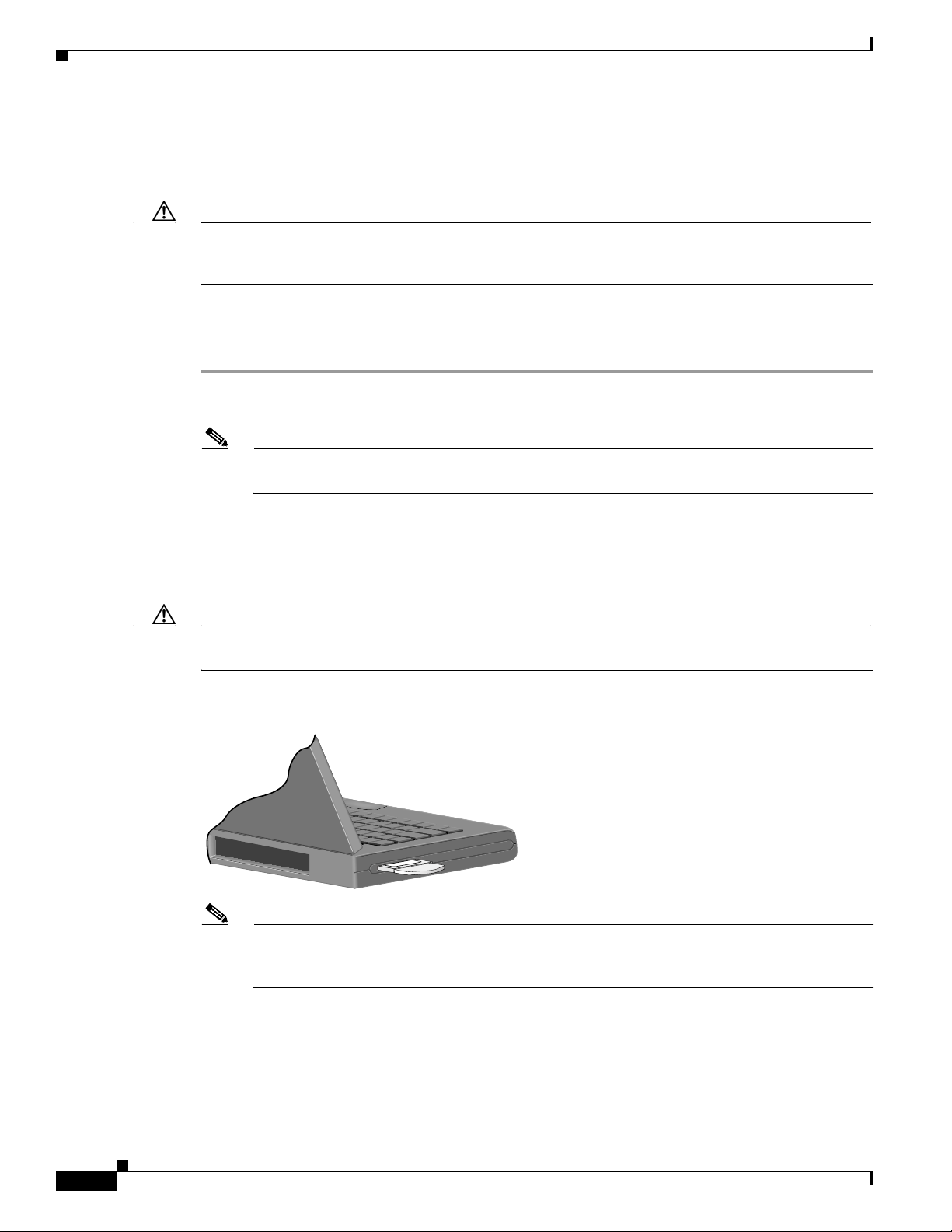
Step 3 Hold the card with the Cisco label facing up and insert it into the Cardbus slot, applying just enough
pressure to make sure it is fully seated (see Figure 3-1). The green LED lights when the card is inserted
properly.
Caution Do not force the card into your computer’s Cardbus slot. Forcing it will damage both the card and the
slot. If the card does not insert easily, remove the card and reinsert it.
Figure 3-1 Inserting a PC-Cardbus Card into a Computer
32617
Note The configuration profiles for PC-Cardbus cards are tied to the slot in which the card is inserted.
Therefore, you must always insert your PC-Cardbus card into the same slot or create profiles for
both slots. See Chapter 4 for information on creating profiles for your client adapter.
3-2
Cisco Aironet 802.11a/b/g Wireless LAN Client Adapters (CB21AG and PI21AG) Installation and Configuration Guide
OL-4211-07
Page 3
Chapter 3 Installing the Client Adapter
Step 4 If the Found New Hardware Wizard window appears, click Cancel.
Note If you do not click Cancel, the wizard will attempt to install software for the client adapter but
Step 5 Go to the “Installing the Client Adapter Software” section on page 3-9.
Inserting a PCI Card
You must perform the following procedures in the order listed below to insert a PCI card:
• Change the bracket (if required), see below
• Insert the card, page 3-4
• Assemble the antenna, page 3-5
• Mount the antenna, page 3-6
Inserting a Client Adapter
will be unable to find it.
Changing the Bracket
The PCI card is shipped with a full-profile bracket attached. If the PC into which you are inserting the
PCI card requires the card to use a low-profile bracket, follow these steps to change brackets.
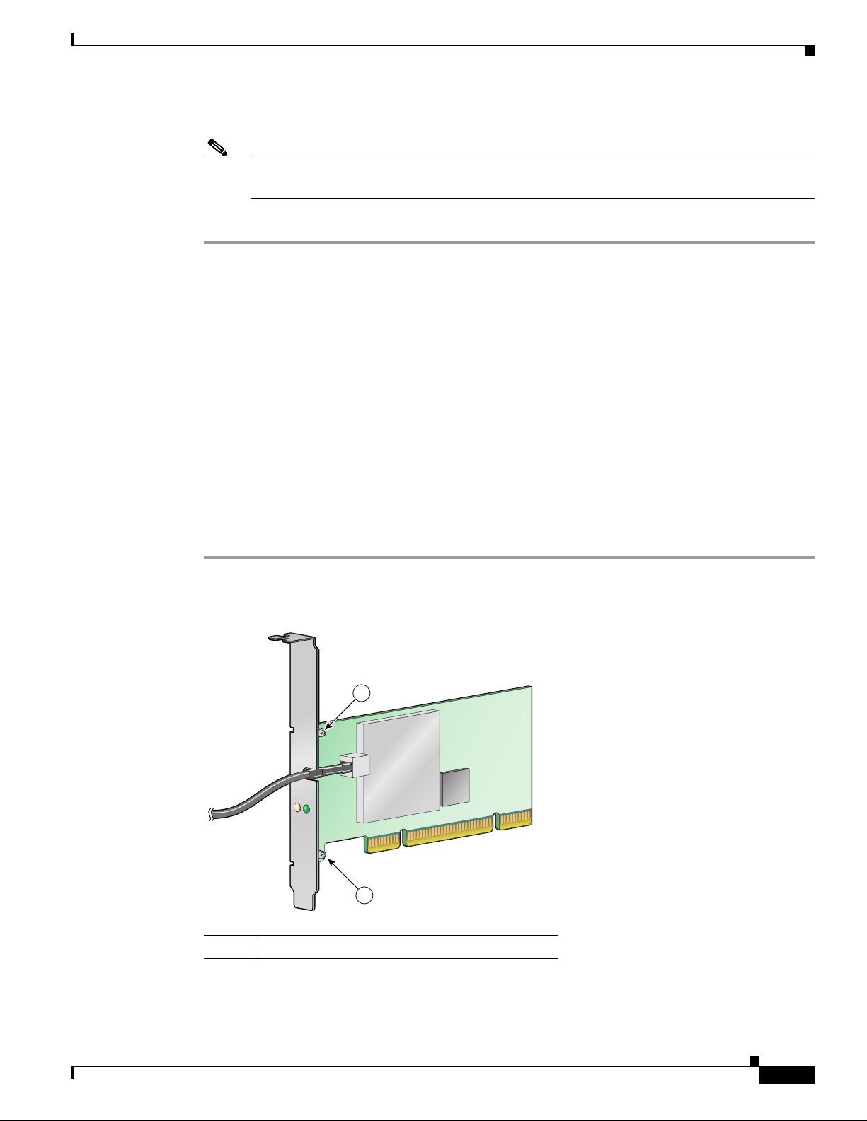
Step 1 Remove the two screws that attach the bracket to the card. See Figure 3-2.
Figure 3-2 Changing the PCI Card Bracket
ACTIVITY
STATUS
1
OL-4211-07
1
1
Cisco Aironet 802.11a/b/g Wireless LAN Client Adapters (CB21AG and PI21AG) Installation and Configuration Guide
Bracket screws
95581
3-3
Page 4

Inserting a Client Adapter
Step 2 Slide the bracket away from the card; then tilt the bracket to free the antenna cable.
Caution Do not pull on the antenna cable or detach it from the PCI card. The antenna is meant to be permanently
Step 3 Hold the low-profile bracket to the card so that the LEDs slip through their corresponding holes on the
Step 4 Insert the screws that you removed in Step 1 into the holes on the populated side of the card near the
Inserting the Card
Step 1 Turn off the PC and all its components.
Step 2 Remove the computer cover.
Chapter 3 Installing the Client Adapter
attached to the card.
bracket.
bracket (see Figure 3-2) and tighten.
Follow the steps below to insert a PCI card into your PC.
Note On most Pentium PCs, PCI expansion slots are white. Refer to your PC documentation for slot
identification.
Step 3 Remove the screw from the top of the CPU back panel above an empty PCI expansion slot. This screw
holds the metal bracket on the back panel.
Caution Static electricity can damage your PCI card. Before removing the card from the anti-static packaging,
discharge static by touching a metal part of a grounded PC.
Step 4 Locate an empty PCI expansion slot inside your computer.
Step 5 Slip your card’s antenna through the opening near the empty expansion slot so that it is located outside
of the computer. See Figure 3-3.
3-4
Cisco Aironet 802.11a/b/g Wireless LAN Client Adapters (CB21AG and PI21AG) Installation and Configuration Guide
OL-4211-07
Page 5
Chapter 3 Installing the Client Adapter
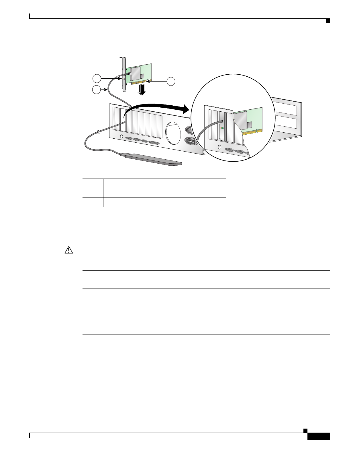
Figure 3-3 Inserting a PCI Card into a PC
2
1
Inserting a Client Adapter
ACTIVITY
STATUS
3
ACTIVITY
STATUS
95582
1
2
3
Step 6 Tilt the card to enable the LEDs to slip through the opening in the CPU back panel. See the enlarged
view in Figure 3-3.
Step 7 Press the card into the empty slot until its connector is firmly seated.
Caution Do not force the card into the expansion slot; this could damage both the card and the slot. If the card
does not insert easily, remove it and reinsert it.
Step 8 Reinstall the screw on the CPU back panel and replace the computer cover.
Assembling the Antenna
Follow the steps below to assemble the PCI card’s antenna.
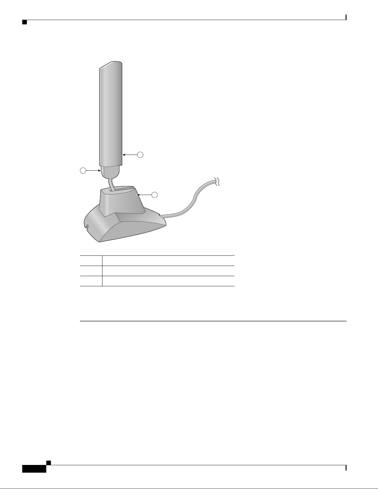
Step 1 Slide the antenna through the opening in the bottom of the antenna base.
Step 2 Position the antenna so its notches are facing the Cisco label on the front of the base. See Figure 3-4.
Antenna cable
LEDs
Card edge connector
OL-4211-07
Cisco Aironet 802.11a/b/g Wireless LAN Client Adapters (CB21AG and PI21AG) Installation and Configuration Guide
3-5
Page 6
Inserting a Client Adapter
Chapter 3 Installing the Client Adapter
Figure 3-4 Inserting the Antenna into Its Base
1
2
3
1
2
3
Step 3 Press the antenna cable into the receptacle on the top of the base as shown in Figure 3-4.
Step 4 Press the antenna straight down into the receptacle until it clicks into place.
Mounting the Antenna
Because the PCI card is a radio device, it is susceptible to RF obstructions and common sources of
interference that can reduce throughput and range. Follow these guidelines to ensure the best possible
performance:
• Place the PCI card’s antenna in an area where large steel structures such as shelving units,
• Place the antenna away from microwave ovens and 2.4- and 5.8-GHz cordless phones. These
95584
Antenna
Notch
Antenna base
bookcases, and filing cabinets will not obstruct radio signals being transmitted or received.
products can cause signal interference because they operate in the same frequency range as the PCI
card.
3-6
Cisco Aironet 802.11a/b/g Wireless LAN Client Adapters (CB21AG and PI21AG) Installation and Configuration Guide
OL-4211-07
Page 7
Chapter 3 Installing the Client Adapter
Follow the steps below to position the PCI card’s antenna on a flat horizontal surface or to mount it to a
wall.
Step 1 Perform one of the following:
• If you want to use the antenna on a flat horizontal surface, position the antenna so it is pointing
straight up. Then go to Step 7.
• If you want to mount the antenna to a wall, go to Step 2.
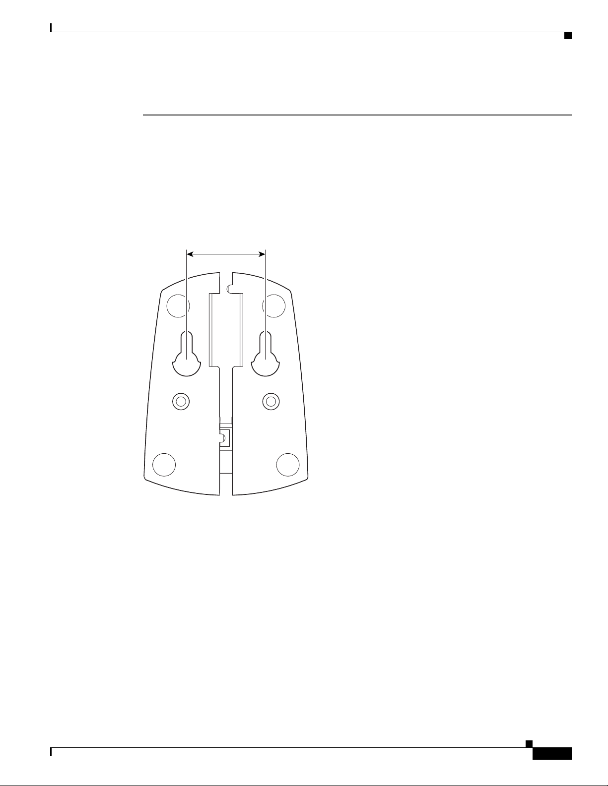
Step 2 Drill two holes in the wall that are 1.09 in. (2.8 cm) apart. Figure 3-5 shows the distance between the
mounting holes on the bottom of the antenna base.
Figure 3-5 Bottom of Antenna Base
Inserting a Client Adapter
1.09 inches
OL-4211-07
95597
Step 3
Step 4 Drive the two supplied screws into the wall anchors, leaving a small gap between the screw head and the
Tap the two supplied wall anchors into the holes.
anchor.
Step 5 Position the mounting holes on the bottom of the antenna base over the screws (see Figure 3-6) and pull
down to lock in place.
Cisco Aironet 802.11a/b/g Wireless LAN Client Adapters (CB21AG and PI21AG) Installation and Configuration Guide
3-7
Page 8

Inserting a Client Adapter
Chapter 3 Installing the Client Adapter
Figure 3-6 Mounting the Antenna
95595
Step 6
The antenna rotates 90 degrees from its base. For optimal reception, position the antenna so it is pointing
straight up (see Figure 3-7).
Figure 3-7 Rotating the Antenna
3-8
95596
Step 7
Boot up your PC. The green LED lights when the card is inserted properly.
Step 8 If the Found New Hardware Wizard window appears, click Cancel.
Step 9 Go to the “Installing the Client Adapter Software” section below.
Cisco Aironet 802.11a/b/g Wireless LAN Client Adapters (CB21AG and PI21AG) Installation and Configuration Guide
OL-4211-07
Page 9

Chapter 3 Installing the Client Adapter
Installing the Client Adapter Software
This section describes how to install Cisco Aironet CB21AG or PI21AG client adapter driver and
utilities from a single executable file named WinClient-802.11a-b-g-Ins-Wizard-vx.exe, where x
represents the release number. Follow these steps to install these client adapter software components on
a computer running Windows 2000 or XP.
Caution Cisco Aironet CB21AG and PI21AG client adapter software is incompatible with other Cisco Aironet
client adapter software. The Aironet Desktop Utility (ADU) must be used with CB21AG and PI21AG
cards, and the Aironet Client Utility (ACU) must be used with all other Cisco Aironet client adapters.
Caution Do not eject your client adapter at any time during the installation process, including during the reboot.
Note This procedure is meant to be used the first time the Cisco Aironet CB21AG or PI21AG client adapter
software is installed on your computer. If this software is already installed on your computer, follow the
instructions in Chapter 9 to upgrade the client adapter software.
Installing the Client Adapter Software
Note Only one CB21AG or PI21AG client adapter can be installed and used at a time. The software does not
support the use of multiple CB21AG or PI21AG cards.
Step 1 Make sure the client adapter is inserted into your computer.
Step 2 Make sure that you have a Cisco Connection Online (CCO) username and password.
Step 3 If you do not have a CCO username and password, go to Cisco’s main page (http://www.cisco.com) and
click Register (top). Then, follow the instructions to create a CCO username and password.
Step 4 Browse to the following location:
http://www.cisco.com/public/sw-center/
Step 5 Click Wireless Software.
Step 6 Click Wireless LAN Access.
Step 7 Click Cisco Wireless LAN Client Adapters.
Step 8 Click Cisco Aironet Wireless LAN Client Adapters.
Step 9 Perform one of the following steps:
• If you are using a PC-Cardbus card, click Cisco Aironet 802.11a/b/g CardBus Wireless LAN
Client Adapter (CB21AG).
• If you are using a PCI card, click Cisco Aironet 802.11a/b/g PCI Wireless LAN Client Adapter
(PI21AG).
Step 10 When prompted, enter your CCO username and password, and click OK.
Step 11 Click Aironet Client Installation Wizard (Firmware, Driver, Utility).
OL-4211-07
Step 12 Click Windows 2000 or Windows XP.
Step 13 Click the link with the greatest release number.
Cisco Aironet 802.11a/b/g Wireless LAN Client Adapters (CB21AG and PI21AG) Installation and Configuration Guide
3-9
Page 10

Installing the Client Adapter Software
Step 14 Click the Install Wizard file (WinClient-802.11a-b-g-Ins-Wizard-vxx.exe), where xx is the version
number.
Step 15 If prompted, enter your CCO username and password, and click OK.
Step 16 Complete the encryption authorization form, read and accept the terms and conditions of the Software
License Agreement, select the file again to download it, and save the file on your computer’s Desktop.
Step 17 Use Windows Explorer to find the installer.
Step 18 Double-click the installer. The “Starting InstallShield Wizard” message appears followed by the
Preparing Setup window (see Figure 3-8) and the Cisco Aironet Installation Program window (see
Figure 3-9).
Figure 3-8 Preparing Setup Window
Chapter 3 Installing the Client Adapter
3-10
Cisco Aironet 802.11a/b/g Wireless LAN Client Adapters (CB21AG and PI21AG) Installation and Configuration Guide
OL-4211-07
Page 11

Chapter 3 Installing the Client Adapter
Figure 3-9 Cisco Aironet Installation Program Window
Installing the Client Adapter Software
Step 19
Click Next. The Setup Type window appears (see Figure 3-10).
OL-4211-07
Cisco Aironet 802.11a/b/g Wireless LAN Client Adapters (CB21AG and PI21AG) Installation and Configuration Guide
3-11
Page 12
Installing the Client Adapter Software
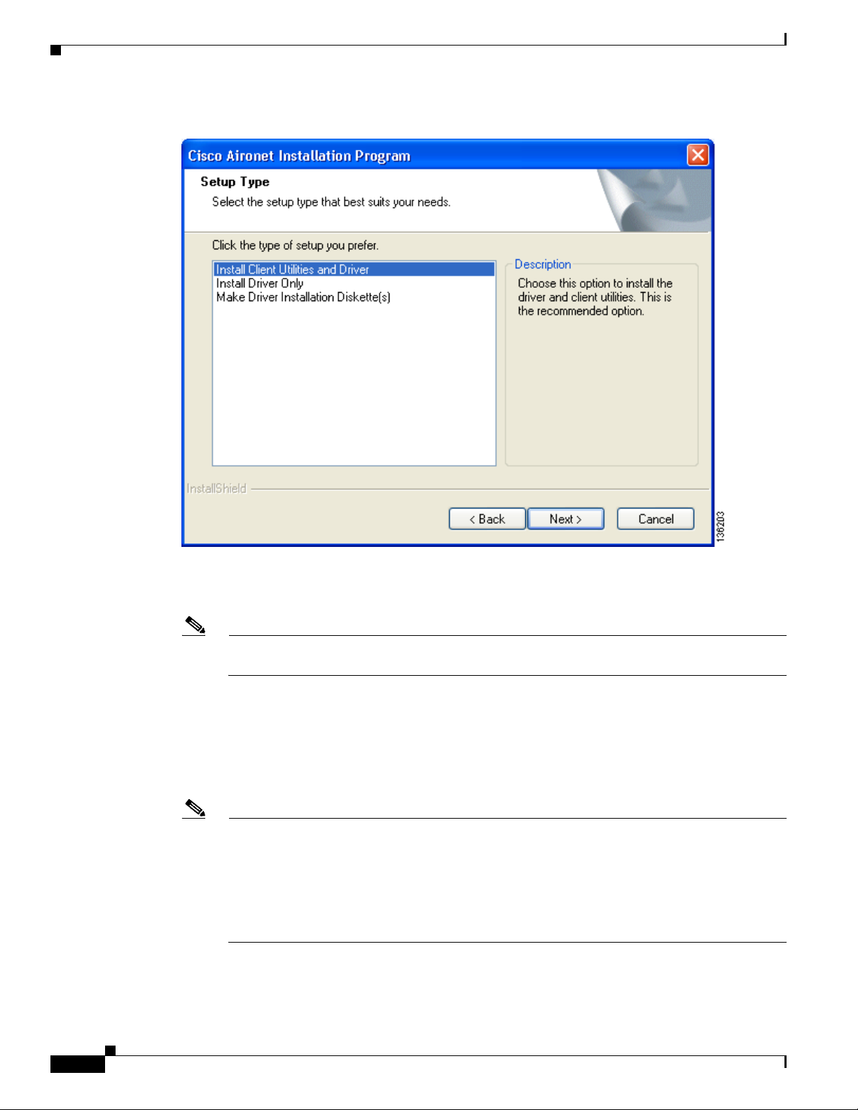
Figure 3-10 Setup Type Window
Chapter 3 Installing the Client Adapter
Step 20
Choose one of the following options and click Next:
Note To ensure compatibility among software components, Cisco recommends that you install the
client utilities and driver.
• Install Client Utilities and Driver—Installs the client adapter driver and client utilities.
• Install Driver Only—Installs only the client adapter driver. If you choose this option, click Next
and go to Step 32.
• Make Driver Installation Diskette(s)—Enables you to create driver installation diskettes that can
be used to install drivers using the Windows Device Manager.
Note If you choose one of the first two options and a client adapter is not inserted into your computer,
the following message appears: “The device may not be present or could have been
ejected/unplugged from the system. Insert or reinsert it now.” Insert the client adapter and click
OK. If you proceed without the client adapter inserted, the installation continues, but the driver
installation is incomplete. You must manually install the driver later using the Update Device
Driver Wizard. See the “Manually Installing or Upgrading the Client Adapter Driver” section on
page 9-6 for instructions.
3-12
Cisco Aironet 802.11a/b/g Wireless LAN Client Adapters (CB21AG and PI21AG) Installation and Configuration Guide
OL-4211-07
Page 13
Chapter 3 Installing the Client Adapter
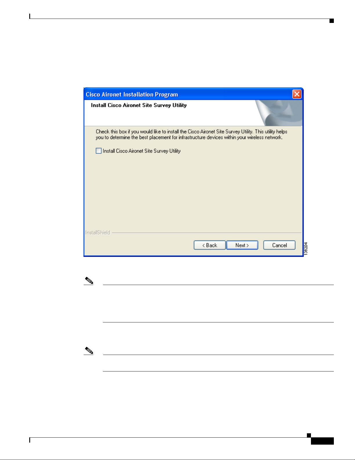
Step 21 When the Install Cisco Aironet Site Survey Utility window appears (see Figure 3-11), check the Install
Cisco Aironet Site Survey Utility check box if you want to install a utility that helps you to determine
the best placement of infrastructure devices within your wireless network. Click Next.
Figure 3-11 Install Cisco Aironet Site Survey Utility Window
Installing the Client Adapter Software
OL-4211-07
Note The site survey utility is a stand-alone application, separate from ADU, that runs from an
executable file. If you check the Install Cisco Aironet Site Survey Utility check box, the Install
Wizard installs the site survey executable file in the C:\Program Files\Cisco Aironet directory
(unless you specify a different directory in Step 23). See Appendix F for instructions on using
the utility.
Step 22 If a message appears indicating that you are required to restart your computer at the end of the
installation process, click Ye s .
Note If you click No, you are asked to confirm your decision. If you proceed, the installation process
terminates.
The Choose Destination Location window appears (see Figure 3-12).
Cisco Aironet 802.11a/b/g Wireless LAN Client Adapters (CB21AG and PI21AG) Installation and Configuration Guide
3-13
Page 14
Installing the Client Adapter Software
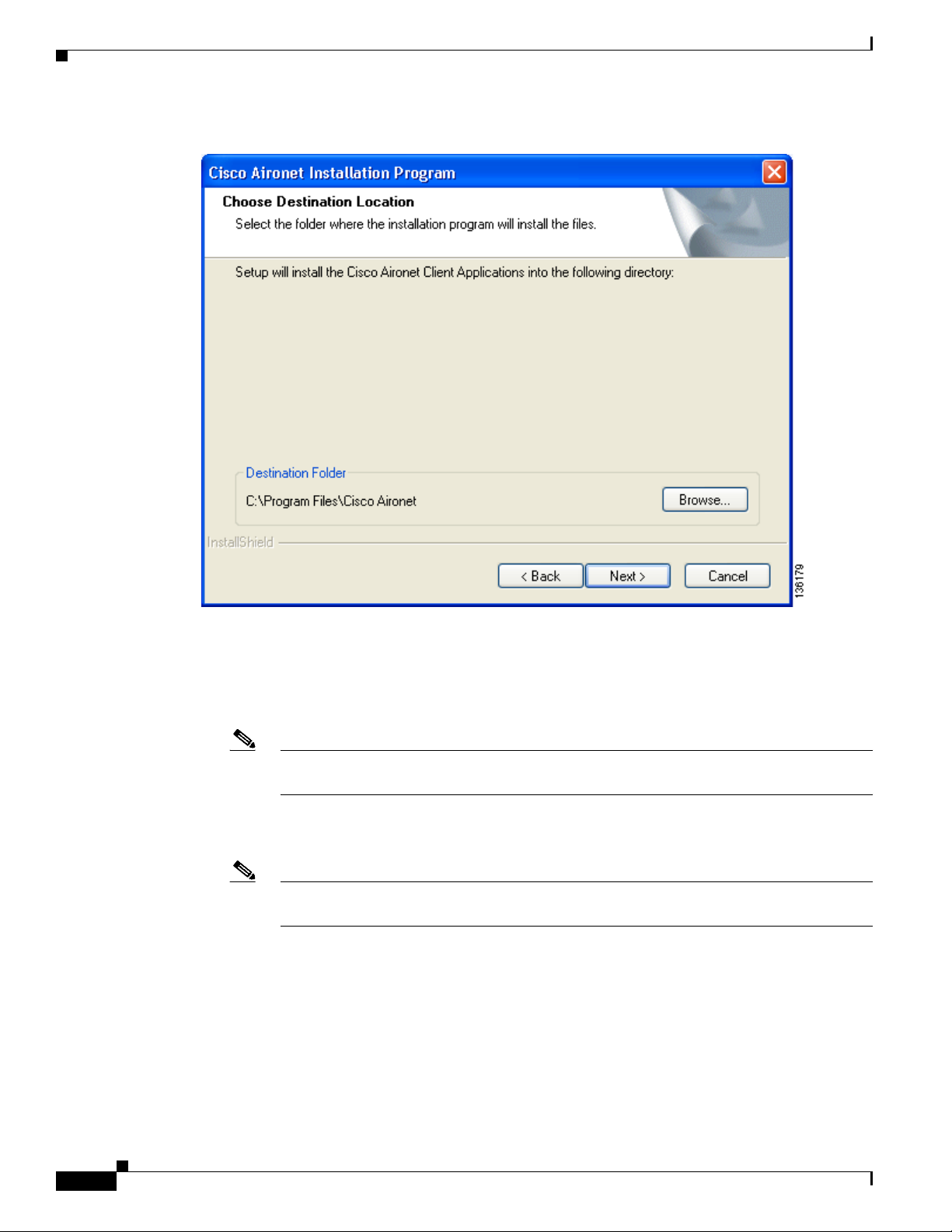
Figure 3-12 Choose Destination Location Window
Chapter 3 Installing the Client Adapter
Step 23
Perform one of the following:
• If you chose the first option in Step 20, click Next to install the client utility files in the C:\Program
Files\Cisco Aironet directory.
Note If you want to install the client utilities in a different directory, click Browse, choose a
different directory, click OK, and click Next.
• If you chose the Make Driver Installation Diskette(s) option in Step 20, insert a floppy disk into your
computer and click Next to copy the driver to the diskette. Go to Step 32.
Note If you want to copy the driver to a different drive or directory, click Browse, choose a new
location, click OK, and click Next.
3-14
Cisco Aironet 802.11a/b/g Wireless LAN Client Adapters (CB21AG and PI21AG) Installation and Configuration Guide
OL-4211-07
Page 15

Chapter 3 Installing the Client Adapter
Step 24 The Select Program Folder window appears (see Figure 3-13).
Figure 3-13 Select Program Folder Window
Installing the Client Adapter Software
Step 25 Click Next to add program icons to the Cisco Aironet program folder.
Note If you want to specify a different program folder, choose a folder from the Existing Folders list
or type a new folder name in the Program Folder field and click Next.
OL-4211-07
Cisco Aironet 802.11a/b/g Wireless LAN Client Adapters (CB21AG and PI21AG) Installation and Configuration Guide
3-15
Page 16

Installing the Client Adapter Software
Step 26 If your computer is running Windows 2000, go to Step 32. If your computer is running Windows XP, the
window titled IMPORTANT: Please Read! appears (see Figure 3-14).
Figure 3-14 IMPORTANT: Please Read! Window
Chapter 3 Installing the Client Adapter
3-16
Cisco Aironet 802.11a/b/g Wireless LAN Client Adapters (CB21AG and PI21AG) Installation and Configuration Guide
OL-4211-07
Page 17

Chapter 3 Installing the Client Adapter
Step 27 Read the information displayed and click Next. The Choose Configuration Tool window appears (see
Figure 3-15).
Figure 3-15 Choose Configuration Tool Window
Installing the Client Adapter Software
OL-4211-07
Step 28
Choose one of the following options:
• Cisco Aironet Desktop Utility (ADU)—Enables you to configure your client adapter using ADU.
• Third-Party Tool—Enables you to configure your client adapter using a third-party tool such as the
Microsoft Wireless Configuration Manager in Windows XP.
Table 3-1 compares Windows XP and ADU client adapter features.
Table 3-1 Comparison of Windows XP and ADU Client Adapter Features
Feature Windows XP ADU
Configuration parameters Limited Extensive
Capabilities
Create profiles Yes Yes
Enable/disable radio No Yes
Cisco Aironet 802.11a/b/g Wireless LAN Client Adapters (CB21AG and PI21AG) Installation and Configuration Guide
3-17
Page 18
Installing the Client Adapter Software
Table 3-1 Comparison of Windows XP and ADU Client Adapter Features (continued)
Feature Windows XP ADU
Security
Static WEP Yes Yes
LEAP or EAP-FAST authentication
with dynamic WEP
EAP-TLS or PEAP authentication Yes Yes
Status and statistics
Status window Limited Extensive
Statistics window (transmit &
receive)
Note If you choose Cisco Aironet Desktop Utility (ADU) above, the Microsoft Wireless
Configuration Manager is disabled. If you ever manually enable it, you are prompted to disable
it whenever ADU is activated.
Chapter 3 Installing the Client Adapter
No Yes
No Yes
Step 29 Click Next.
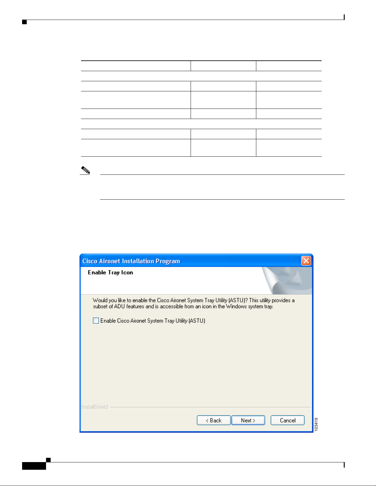
Step 30 If you chose Cisco Aironet Desktop Utility (ADU) in Step 28, go to Step 32. If you chose Third-Party
Tool, the Enable Tray Icon window appears (see Figure 3-16).
Figure 3-16 Enable Tray Icon Window
3-18
Cisco Aironet 802.11a/b/g Wireless LAN Client Adapters (CB21AG and PI21AG) Installation and Configuration Guide
OL-4211-07
Page 19

Chapter 3 Installing the Client Adapter
Step 31 Check the Enable Cisco Aironet System Tray Utility (ASTU) check box if you want to be able to use
ASTU even though you have chosen to configure your client adapter through a third-party tool instead
of ADU and click Next.
Step 32 When prompted to insert your client adapter, click OK. The Setup Status window appears (see
Figure 3-17).
Figure 3-17 Setup Status Window
Installing the Client Adapter Software
OL-4211-07
The installation process begins, and you are notified as each software component is installed.
Step 33 When a message appears indicating that your computer needs to be rebooted, click OK and allow your
computer to restart.
Step 34 If the Windows Found New Hardware Wizard appears after your computer reboots, click Next, allow the
wizard to install the software for the client adapter, and click Finish.
Step 35 If your network setup does not include a DHCP server and you plan to use TCP/IP, follow these steps
for your operating system.
• Windows 2000
a. Double-click My Computer, Control Panel, and Network and Dial-up Connections.
b. Right-click Local Area Connection x (where x represents the number of the connection).
c. Click Properties.
d. In the Components Checked Are Used by This Connection field, click Internet Protocol
(TCP/IP) and Properties.
Cisco Aironet 802.11a/b/g Wireless LAN Client Adapters (CB21AG and PI21AG) Installation and Configuration Guide
3-19
Page 20

Installing the Intermediate Driver Manually
e. Choose Use the following IP address and enter the IP address, subnet mask, and default gateway
address of your computer (which can be obtained from your system administrator).
f. Click OK to close each open window.
• Windows XP
a. Double-click My Computer, Control Panel, and Network Connections.
b. Right-click Wireless Network Connection x (where x represents the number of the connection).
c. Click Properties.
d. In the This Connection Uses the Following Items field, click Internet Protocol (TCP/IP) and
Properties.
e. Choose Use the following IP address and enter the IP address, subnet mask, and default gateway
address of your computer (which can be obtained from your system administrator).
f. Click OK to close each open window.
Step 36 If you are prompted to restart your computer, click Ye s.
Step 37 Now that your client adapter is properly installed, it is ready to be configured.
• If you are planning to configure your client adapter through ADU, go to Chapter 4 to create
configuration profiles.
• If you are planning to configure your client adapter through the Windows XP Wireless Configuration
Manager, go to Appendix E.
• If you are planning to configure your client adapter through another third-party tool, refer to the
documentation for that application.
Chapter 3 Installing the Client Adapter
Note If you want to be able to use ADU’s Group Policy Delay parameter, follow the instructions below to
download and install a necessary hot fix before configuring your client adapter.
Note If you experienced problems during or after installation, refer to Chapter 10 for troubleshooting
information.
Installing the Intermediate Driver Manually
In some instances, the installation of the CB21AG software might not work as expected because the
intermediate driver might not have installed correctly. In this situation, the installer might not detect this
condition, and the rest of the software will not function correctly.
The CB21AG intermediate driver must be installed manually. To install the intermediate driver manually,
follow these steps:
Step 1 Insert the client adapter.
Step 2 Click on "Network Connections" in the Start > Settings menu in Windows XP, or right click on "My
Network Places" in Windows 2000. Find the CB21AGg instance.
3-20
Cisco Aironet 802.11a/b/g Wireless LAN Client Adapters (CB21AG and PI21AG) Installation and Configuration Guide
OL-4211-07
Page 21

Chapter 3 Installing the Client Adapter
Installing a Microsoft Hot Fix for Group Policy Delay
Step 3 Right click on the Cisco CB21AG instance, and left click on Properties.
Step 4 Choose the "Install" option and then add a new service.
Step 5 Choose the "Have disk" button. Go to \windows\system32 directory and choose wsimd.inf.
Step 6 Highlight and select "Wireless Intermediate Driver" and click "ok" button. The wireless IMD is bound
to the adapter.
Step 7 Reboot system.
Installing a Microsoft Hot Fix for Group Policy Delay
If you want to use the Group Policy Delay parameter on the Profile Management (Security) window in
ADU, you must install a Microsoft hot fix on computers running Windows 2000. The hot fix is
incorporated into Windows XP Service Pack 2 and later.
The Group Policy Delay parameter enables you to specify how much time elapses before the Windows
logon process starts Group Policy, a Windows feature used by administrators to specify configuration
options for groups of users. The objective is to delay the start of Group Policy until wireless network
authentication occurs. Follow the steps below to obtain and install the hot fix.
Note You must be a registered Cisco customer and log into Cisco.com in order to download the hot fix. If you
are unable to access the hot fix from Cisco.com, contact Microsoft Support to obtain it. The Windows
2000 support page provides the contact information:
http://support.microsoft.com/default.aspx?scid=fh;EN-US;win2000
Step 1 Use your computer’s web browser to access the following URL:
http://www.cisco.com/cgi-bin/tablebuild.pl/aironet_hotfix
Step 2 If prompted, enter your Cisco Connection Online (CCO) username and password, and click OK.
Note To create a CCO username and password, visit http://www.cisco.com.
Step 3 Click the hot fix file (userenv.zip).
Step 4 Complete the encryption authorization form and click Submit.
Step 5 Click the file again to download it.
Step 6 Save the file to your computer’s hard drive.
Step 7 Find the file using Windows Explorer, double-click it, and extract its files to a folder.
Step 8 Reboot your computer and press F8 while your computer is booting.
Step 9 When the boot menu appears, select Safe Mode with Command Prompt.
OL-4211-07
Note You must complete this procedure in safe mode; otherwise, system file protection (SFP) will
silently restore the original version of the file you are replacing.
Cisco Aironet 802.11a/b/g Wireless LAN Client Adapters (CB21AG and PI21AG) Installation and Configuration Guide
3-21
Page 22

Installing a Microsoft Hot Fix for Group Policy Delay
Step 10 Copy the hot fix file (userenv.dll) to %systemroot%\System32 and overwrite the existing version of this
file.
Step 11 Delete the copy of userenv.dll in %systemroot%\System32\DllCache.
Step 12 Reboot your computer.
Chapter 3 Installing the Client Adapter
3-22
Cisco Aironet 802.11a/b/g Wireless LAN Client Adapters (CB21AG and PI21AG) Installation and Configuration Guide
OL-4211-07
 Loading...