

Page 1

Installation
This chapter provides procedures for installing the Cisco 815 integrated services
router and includes the following sections:
• Before Installing the Router
• Connecting the Router to Your Local Network
• Connecting Power to the Router
• Verifying Your Installation
• Optional Installation Procedures
Before Installing the Router
The Cisco 815 integrated services router is shipped ready for desktop mounting.
Before you connect it to the power and network, simply set the router on a
desktop, shelf, or other flat surface.
Be sure to read the safety information in the Regulatory Compliance and Safety
Information for Cisco 800 Series and SOHO Series Routers document online.
CHAPTER
2
OL-9558-01
Warning
Read the installation instructions before you connect the system to its power
source.
Cisco 815 Integrated Services Router Hardware Installation Guide
2-1
Page 2

Connecting the Router to Your Local Network
Chapter 2 Installation
Warning
Before working on equipment that is connected to power lines, remove jewelry
(including rings, necklaces, and watches). Metal objects will heat up when
connected to power and ground and can cause serious burns or weld the metal
object to the terminals. (Tosee translated versions of this warning, refer to the
Regulatory Compliance and Safety Information for Cisco 800 Series and SOHO
Series Routers
Warning
Caution Do not place anything on top of the router that weighs more than 10 pounds
Do not work on the system or connect or disconnect cables during periods of
lightning activity.
document that came with the router.)
(4.5 kg). Excessive weight on top of the router could damage the chassis.
Caution There are no field-replaceable parts inside the router. Do not open the router
enclosure to replace parts.
Caution To prevent damage to the chassis, never attempt to lift of tilt the chassis by the
plastic panel on the front. Always hold the chassis by the metal body.
Connecting the Router to Your Local Network
The Cisco 815 integrated services router is connected to your local Ethernet
network through the yellow 10/100 Ethernet port. Youmust provide the following
items for this connection:
• A straight-through, RJ-45-to-RJ-45, Ethernet cable
• A 10/100-Mbps Ethernet hub or switch
Cisco 815 Integrated Services Router Hardware Installation Guide
2-2
OL-9558-01
Page 3

Chapter 2 Installation
Caution Do not connect a WAN cable to the card until you have completed the installation
Note For details about specific WAN interface cards (WICs), connecting the card to the
Connecting the Router to Your Local Network
procedure.
WAN line, and configuring the interface with Cisco IOS software, see the
Cisco Interface Cards Hardware Installation Guide.
Warning
The ports labeled 10/100 ETHERNET and CONSOLE are safety extra-low voltage
(SELV) circuits. SELV circuits should only be connected to other SELV circuits.
Because BRI circuits are treated like telephone-network voltage, avoid
connecting the SELV circuits to the telephone network voltage (TNV) circuits.
(To see translated versions of this warning, refer to the
Regulatory Compliance
andSafetyInformationforCisco800 Series and SOHO Series Routers
that came with the router.)
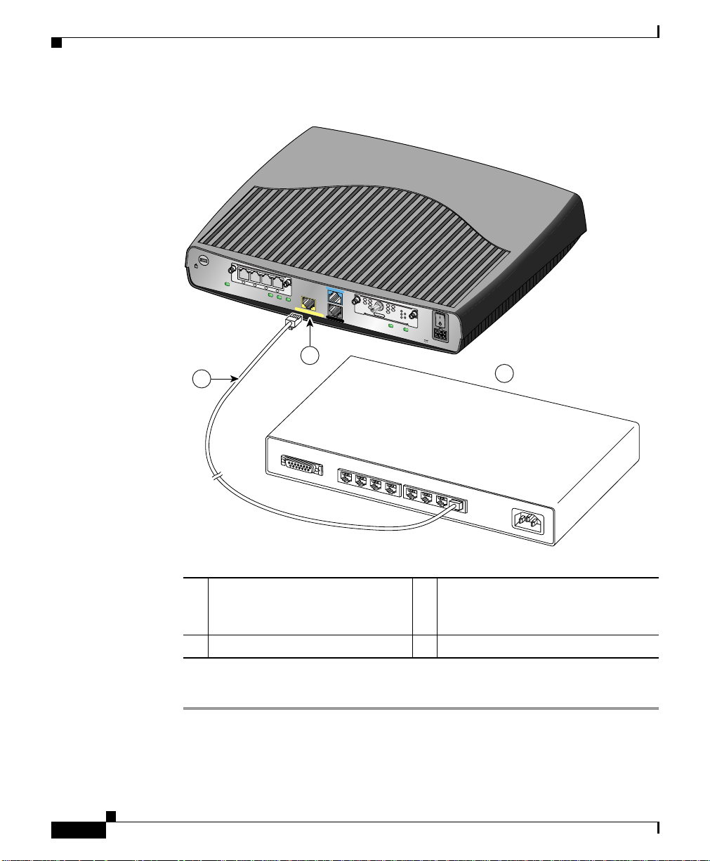
Follow these steps to connect the router to the local network:
Step 1 Connect one end of the cable to the yellow Ethernet port (labeled
10/100 ETHERNET) on the back panel of the router, as shown in Figure 2-1.
document
OL-9558-01
Cisco 815 Integrated Services Router Hardware Installation Guide
2-3
Page 4
Connecting the Router to Your Local Network
Figure 2-1 Connecting the Router to the Local Network
WIC
4ESW
Cisco 815
WIC0OK
4xACT LNK
3xACT LNK
2xACT LNK
FDX
2
Chapter 2 Installation
10/100 ETHERNET
CONSOLE
HWIC-CABLE-D-2
AUX
DS
US
CABLE
LINK
ONLINE
POWER
MODOK
WIC1OK
+5, +12, -12 VDC
1xACT LNK
LINK100
1
3
2-4
AUI
1
10/100 Ethernet port on the
8
7
6
5
4
3
2
1
3
Ethernet hub or switch
Cisco 815 integrated services
router
2
Straight-through Ethernet cable
Step 2 Connect the other end of the cable to a network port on the hub or switch.
Cisco 815 Integrated Services Router Hardware Installation Guide
OL-9558-01
155186
Page 5
Chapter 2 Installation
Connecting Power to the Router
Read the following warnings before connecting the router to power.
Connecting Power to the Router
Warning
Warning
The power supply is designed to work with TN power systems.
This equipment is intended to be grounded. Ensure that the host is connected to
earth ground during normal use.
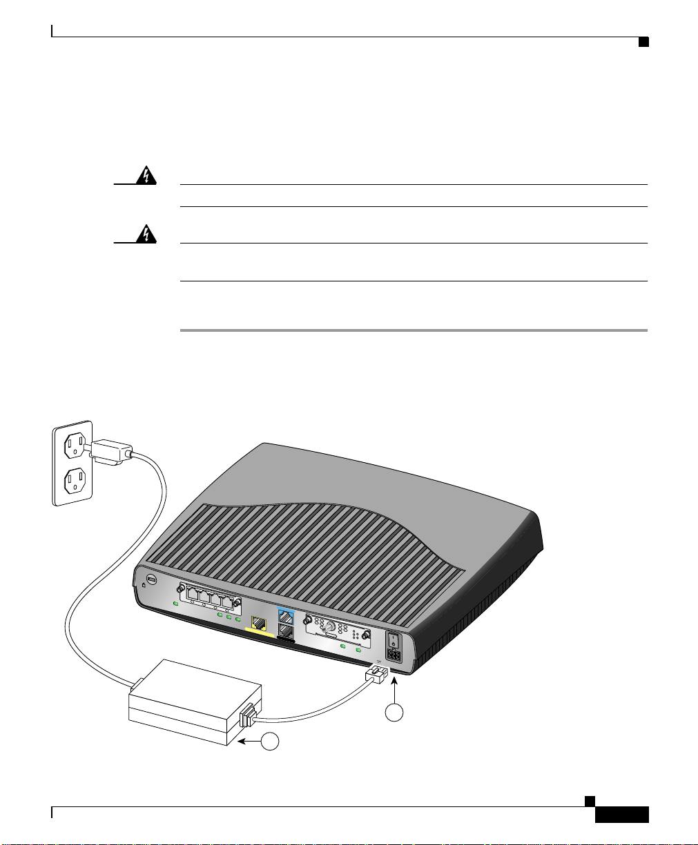
Follow these steps to connect power to the router and to turn on the router:
Step 1 Connect the attached power-supply cord to the power socket (labeled +5, +12,
-12 VDC) on the router back panel, as shown in Figure 2-2.
Figure 2-2 Connecting the Power Supply
WIC
4ESW
Cisco 815
WIC0OK
4xACT LNK
3xACT LNK
2xACT LNK
1xACT LNK
FDX
LINK100
10/100 ETHERNET
CONSOLE
HWIC-CABLE-D-2
AUX
155187
DS
US
CABLE
LINK
ONLINE
POWER
MODOK
WIC1OK
+5, +12, -12 VDC
OL-9558-01
2
1
Cisco 815 Integrated Services Router Hardware Installation Guide
2-5
Page 6

Verifying Your Installation
Chapter 2 Installation
1
Power supply
Step 2 Connect one end of the separate power cord to the socket on the power supply.
Step 3 Connect the other end of the separate power cord to a power outlet.
Step 4 Press the router power switch to ON ( | ).
Step 5 Confirm that the router has power by checking that the PWR LED on the front
2
Power socket
panel is on.
Verifying Your Installation
You can verify that you have correctly installed the router by checking the
following LEDs:
• PWR (front panel)—On when power is being supplied to the router.
• OK (front panel)—On when the router software is loaded and functional.
Blinking indicates that the router is performing a power-on self-test (POST).
• WIC0/WIC1 OK (back panel)—On when the WIC is correctly installed in the
corresponding WIC slot.
• ETH ACT (front panel)—Blinking when there is network traffic on the local
10/100 Ethernet LAN.
• WIC0 ACT or WIC1 ACT (front panel)—Varies, depending on the WIC
installed. See Table 1-4 in Chapter 1, “Overview.”
• LINK (back panel)—On when the router is correctly connected to the local
Ethernet LAN through the 10/100 ETHERNET port.
• MOD OK (back panel)—On when the VPN hardware encryption module is
installed and recognized by the Cisco IOS software.
2-6
Cisco 815 Integrated Services Router Hardware Installation Guide
OL-9558-01
Page 7

Chapter 2 Installation
Optional Installation Procedures
This section describes some installation procedures that you might or might not
use, depending on your site and on how you are configuring the router. This
section describes the following procedures:
• Connecting a PC
• Connecting a Modem
• Stacking the Router
• Unstacking the Router
Connecting a PC
If you want to use the Cisco IOS command-line interface to configure the router,
you must connect the router console port to a terminal or PC. The cable and
adapter required for this connection are included with the router.
If you want to use a PC to configure the router, you need to make sure that the PC
has some type of terminal emulation software installed. The software should be
configured with the following parameters: 9600 baud, 8 data bits, no parity bits,
1 stop bit.
Follow these steps to connect the router to a terminal or PC:
Optional Installation Procedures
OL-9558-01
Step 1 Connect the blue console cable to the blue console port on the back of the router,
as shown in Figure 2-3.
Cisco 815 Integrated Services Router Hardware Installation Guide
2-7
Page 8

Optional Installation Procedures
Figure 2-3 Connecting the Console Cable to the Router
WIC
4ESW
4x
Cisco 815
WIC0OK
3x
ACT LNK ACT LNK ACT LNK
2x
ACT LNK
1x
FDX
LINK100
10/100 ETHERNET
CONSOLE
AUX
HWIC-CABLE-D-2
DS
US
CABLE
MODOK
ONLINE
WIC1OK
LINK
POWER
+5, +12, -12 VDC
Chapter 2 Installation
4
1
Blue console cable
2
Console port
Step 2 Connect the DB-9 end of the console cable to the console port (also called the
Cisco 815 Integrated Services Router Hardware Installation Guide
2-8
1
2
3
146793
3
To PC or terminal
4
Cisco 815 integrated services router
serial port) on your PC. If this adapter does not fityour PC console port, you must
provide an adapter that fits.
OL-9558-01
Page 9

Chapter 2 Installation
Connecting a Modem
When a modem is connected to the auxiliary port, a remote user can dial in to the
router and configure it. You can use the console cable provided in the accessory
kit.
Follow these steps to connect a modem to the router, using the console cable:
Step 1 Connect the RJ-45 end of the cable to the black AUX port on the back of the
router, as shown in Figure 2-4.
Figure 2-4 Connecting a Modem to the Router
Optional Installation Procedures
OL-9558-01
WIC
4ESW
Cisco 815
WIC0OK
4xACT LNK
3xACT LNK
2
1
AUX port (RJ-45)
2
Console cable
2xACT LNK
1xACT LNK
FDX
LINK100
10/100 ETHERNET
CONSOLE
HWIC-CABLE-D-2
DS
US
CABLE
LINK
ONLINE
AUX
MODOK
WIC1OK
POWER
+5, +12, -12 VDC
1
4
3
3
DB-9-to-DB-25 adapter
4
Modem
Cisco 815 Integrated Services Router Hardware Installation Guide
155188
2-9
Page 10

Optional Installation Procedures
Step 2 Connect the DB-9 end of the cable to the DB-9 end of the DB-9-to-DB-25 adapter.
Step 3 Connect the DB-25 end of the adapter to the modem.
Stacking the Router
You can stack one Cisco 815 integrated services router in a four-device stack,
along with other Cisco products designed for stacking with the router. Using a
stacking clip and fastener, you can stack each device directly on top of another
device.
Note The Cisco 815 integrated services router is not shipped with the stacking
equipment described in this section; however, the equipment is included with all
other Cisco products that are designed to be stacked.
Other Cisco products designed to be stacked with the router comes with a stacking
clip and a fastener for keeping the multiple devicestogether in a stack. Before you
stack the devices, assemble the clip and fastener as shown in Figure 2-5.
Chapter 2 Installation
2-10
Cisco 815 Integrated Services Router Hardware Installation Guide
OL-9558-01
Page 11

Chapter 2 Installation
Figure 2-5 Assembling Stacking Clip and Fastener
Optional Installation Procedures
Push plastic fastener
through small hole
at the end of the
stacking clip.
OL-9558-01
H11542
After assembling the clip and fastener, follow these steps to stack the router with
another device:
Step 1 Place the clip on top of the lower device, as shown in Figure 2-6. Slide the clip
forward so that the front tabs slide into the vent slots. Make sure that the back
hooks fit over the edge of the lower device.
Cisco 815 Integrated Services Router Hardware Installation Guide
2-11
Page 12

Optional Installation Procedures
Figure 2-6 Stacking the Router (Back View)
Cisco 815
WIC0OK
Chapter 2 Installation
1
WIC
4ESW
4xACT LNK
3xACT LNK
2xACT LNK
1xACT LNK
FDX
LINK100
10/100 ETHERNET
CONSOLE
HWIC-CABLE-D-2
DS
US
LINK
CABLE
ONLINE
AUX
MODOK
WIC1OK
POWER
+5, +12, -12 VDC
2
WIC
4ESW
Cisco 815
4xACT LNK
ACT LNK
3x
2xACT LNK
WIC0OK
1xACT LNK
FDX
3
LINK100
10/100 ETHERNET
CONSOLE
HWIC-CABLE-D-2
AUX
4
3
1
Slot on bottom of router (see also
DS
US
LINK
CABLE
ONLINE
POWER
MODOK
WIC1OK
+5, +12, -12 VDC
4
Back panel of lower hub
5
155189
#5)
2
Front tabs
5
Plastic fastener, which fits into slot
on bottom of router (see #1)
3
Back hooks
Step 2 Position the router onto the clip so that the back hooks fit over the edge of the
router.
Step 3 Position the plastic fastener into the slot on the bottom of the router.
Step 4 Snap the router onto the clip by pushing it down.
2-12
Cisco 815 Integrated Services Router Hardware Installation Guide
OL-9558-01
Page 13

Chapter 2 Installation
Unstacking the Router
Follow these steps to unstack the router from another device:
Step 1 Press up on the tab over the center of the lower device to release the clip from the
vent, as shown in Figure 2-7.
Figure 2-7 Unstacking the Router
3
2
WIC
4ESW
Cisco 815
Cisco 815
WIC0OK
WIC0OK
4xACT LNK
3xACT LNK
ACT
2x
LNK
1xACT LNK
FDX
LINK100
10/100 ETHERNET
10/100 ETHERNET
CONSOLE
1
WIC
4ESW
4xACT LNK
3xACT LNK
2xACT LNK
1xACT LNK
FDX
LINK100
CONSOLE
10/100 ETHERNET
Optional Installation Procedures
HWIC-CABLE-D-2
AUX
HWIC-CABLE-D-2
AUX
DS
US
CABLE
LINK
ONLINE
POWER
MODOK
WIC1OK
+5, +12, -12 VDC
DS
US
CABLE
LINK
ONLINE
POWER
MODOK
WIC1OK
+5, +12, -12 VDC
155190
OL-9558-01
Step 2 Slide the clip and router toward you.
Step 3 Use both hands to lift the router and the stacking clip off the lower device.
Afterward, remove the clip from the bottom of the router.
Cisco 815 Integrated Services Router Hardware Installation Guide
2-13
Page 14

Optional Installation Procedures
Chapter 2 Installation
2-14
Cisco 815 Integrated Services Router Hardware Installation Guide
OL-9558-01
 Loading...