

Page 1

APPENDIX
Case Study: Troubleshooting
Cisco Unified IP Phone Calls
This appendix contains two case studies:
• Troubleshooting Intracluster Cisco Unified IP Phone Calls
• Troubleshooting Intercluster Cisco Unified IP Phone Calls
Troubleshooting Intracluster Cisco Unified IP Phone Calls
The case study in this section discusses in detail the call flow between two Cisco Unified IP Phones
within a cluster, called an intracluster call. This case study also focuses on Cisco Unified CallManager
and Cisco Unified IP Phone initialization, registration, and keepalive processes. A detailed explanation
of an intracluster call flow follows the discussion. The explanation of the processes are explained using
the trace utilities and tools discussed in Chapter 2, “Troubleshooting Tools.”
This section contains the following topics:
B
• Sample Topology
• Cisco Unified IP Phone Initialization Process
• Cisco Unified CallManager Initialization Process
• Self-Starting Processes
• Cisco Unified CallManager Registration Process
• Cisco Unified CallManager KeepAlive Process
• Cisco Unified CallManager Intracluster Call Flow Traces
Sample Topology
Given that you have two clusters named Cluster 1 and Cluster 2, the two Cisco Unified CallManagers in
Cluster 1 are called Unified CM3 and Unified CM4, while the two Cisco Unified CallManagers in
Cluster 2 are called Unified CM1 and Unified CM2.
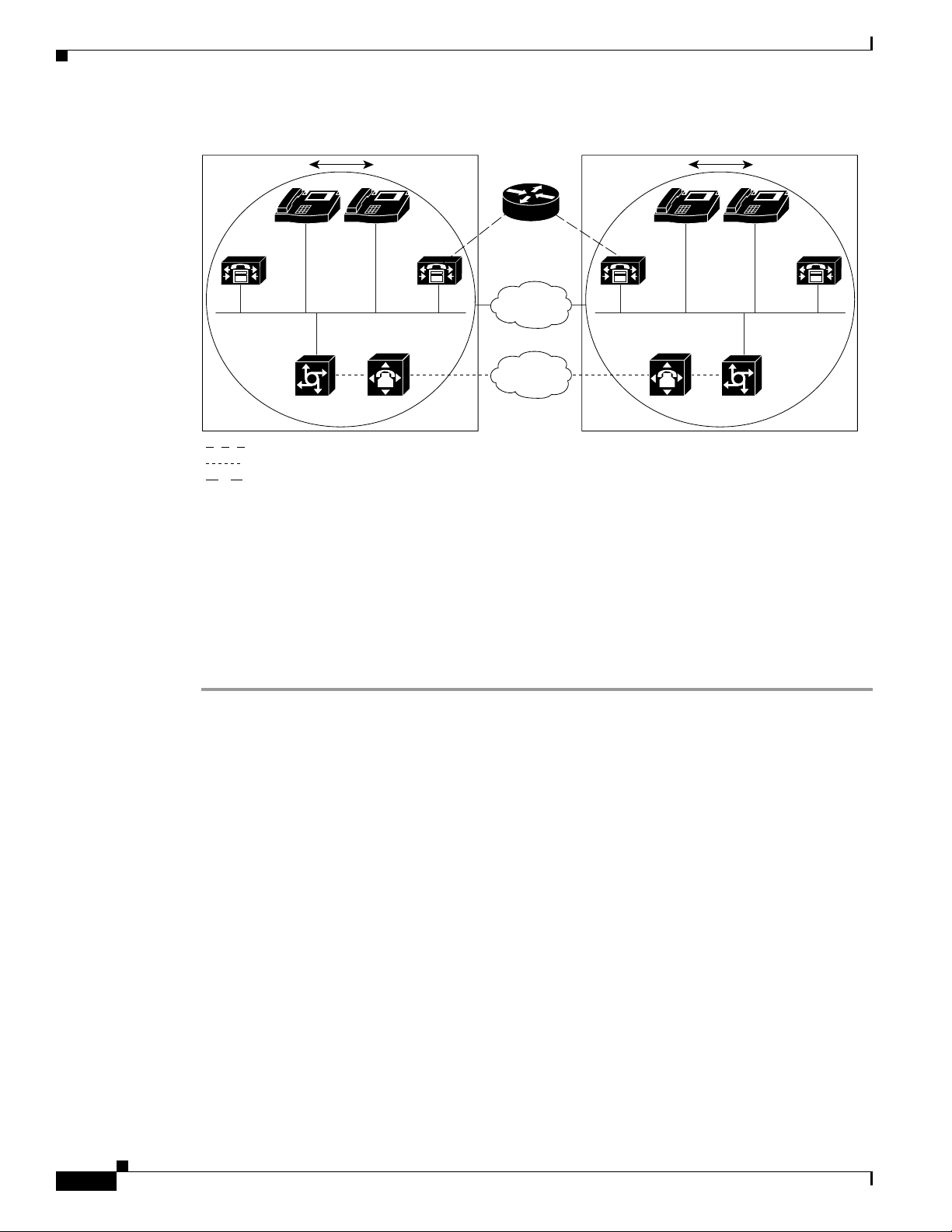
The traces collected for this case study come from Unified CM1, which is located in Cluster 2, as shown
in Figure B-1. The basis for the call flow are the two Cisco Unified IP Phones in Cluster 2. The IP
addresses of these two Cisco IP Phones are 172.16.70.230 (directory number 1000) and 172.16.70.231
(directory number 1001), respectively.
OL-9420-01
Troubleshooting Guide for Cisco Unified CallManager Release 5.0(2)
B-1
Page 2
Troubleshooting Intracluster Cisco Unified IP Phone Calls
Figure B-1 Sample Topology of Intracluster Cisco IP Phone-to-Cisco IP Phone Calls
Appendix B Case Study: Troubleshooting Cisco Unified IP Phone Calls
IOS Gatekeeper
IP IP
Unified
CM3
172.16.70.245 172.16.70.243
Cluster 1
Zone 1
= T1/PRI
= T1/CAS
= RAS
Unified
CM4
172.16.70.241
172.16.70.255
IP WAN
Cisco Unified IP Phone Initialization Process
The following procedure explains in detail the Cisco Unified IP Phone initialization (or boot up)
process.
PSTN
IP IP
Unified
CM1
172.16.70.228 172.16.70.229
Cluster 2
Unified
CM2
Zone 2
141754
Procedure
Step 1 If you have set the appropriate options in DHCP server (such as Option 066 or Option 150), the
Cisco Unified IP Phone sends a request, at initialization to the DHCP server to get an IP address,
Domain Name System (DNS) server address, and TFTP server name or address. It also gets a default
gateway address if you have set these options in the DHCP server (Option 003).
Step 2 If a DNS name of the TFTP sever is sent by DHCP, you need a DNS server IP address to map the name
to an IP address. Bypass this step if the DHCP server sends the IP address of the TFTP server. In this
case study, the DHCP server sent the IP address of TFTP because DNS was not configured.
Step 3 If a TFTP server name is not included in the DHCP reply, the Cisco IP Phone uses the default server
name.
Step 4 The configuration file (.cnf) file gets retrieved from the TFTP server. All .cnf files have the name
SEP<mac_address>.cnf. If this is the first time the phone is registering with the
Cisco Unified CallManager, a default file, SEPdefault.cnf, gets downloaded to the
Cisco Unified IP Phone. In this case study, the first Cisco Unified IP Phone uses the IP address
172.16.70.230 (its MAC address is SEP0010EB001720), and the second Cisco Unified IP Phone uses
the IP address 172.16.70.231 (its MAC address is SEP003094C26105).
Step 5 All .cnf files include the IP address(es) for the primary and secondary Cisco Unified CallManager(s).
The Cisco Unified IP Phone uses this IP address to contact the primary Cisco Unified CallManager and
to register.
B-2
Troubleshooting Guide for Cisco Unified CallManager Release 5.0(2)
OL-9420-01
Page 3

Appendix B Case Study: Troubleshooting Cisco Unified IP Phone Calls
Troubleshooting Intracluster Cisco Unified IP Phone Calls
Step 6 Once the Cisco Unified IP Phone connects and registers with Cisco Unified CallManager, the
Cisco Unified CallManager tells the Cisco Unified IP Phone which executable version (called a load ID)
to run. If the specified version does not match the executing version on the Cisco Unified IP Phone, the
Cisco Unified IP Phone will request the new executable from the TFTP server and reset automatically.
Cisco Unified CallManager Initialization Process
This section explains the initialization process of Cisco Unified CallManager with the help of traces that
are captured from Unified CM1 (identified by the IP address 172.16.70.228). As described previously,
SDI traces provide a very effective troubleshooting tool because they detail every packet sent between
endpoints.
This section describes the events that occur when Cisco Unified CallManager is initialized.
Understanding how to read traces will help you to properly troubleshoot the various
Cisco Unified CallManager processes and the effect of those processes on services such as conferencing
and call forwarding.
The following messages from the Cisco Unified CallManager SDI trace utility show the initialization
process on one of the Cisco Unified CallManagers, in this case, Unified CM1.
• The first message indicates that Cisco Unified CallManager started its initialization process.
• The second message indicates that Cisco Unified CallManager read the default database values (for
this case, it is the primary or publisher database).
• The third message indicates Cisco Unified CallManager received the various messages on TCP port
8002.
• The fourth message shows that, after receiving to these messages, Cisco Unified CallManager added
a second Cisco Unified CallManager to its list: Unified CM2 (172.16.70.229).
• The fifth message indicates that Cisco Unified CallManager has started and is running
Cisco Unified CallManager version 3.1(1).
16:02:47.765 CCM|CMProcMon - CallManagerState Changed - Initialization Started.
16:02:47.796 CCM|NodeId: 0, EventId: 107 EventClass: 3 EventInfo: Cisco CCMDatabase
Defaults Read
16:02:49.937 CCM| SDL Info - NodeId: [1], Listen IP/Hostname: [172.16.70.228], Listen
Port: [8002]
16:02:49.984 CCM|dBProcs - Adding SdlLink to NodeId: [2], IP/Hostname: [172.16.70.229]
16:02:51.031 CCM|NodeId: 1, EventId: 1 EventClass: 3 EventInfo: Cisco CallManager
Version=<3.1(1)> started
Self-Starting Processes
Once Cisco Unified CallManager is up and running, it starts several other processes within itself. Some
of these processes follow, including MulticastPoint Manager, UnicastBridge Manager, digit analysis,
and route list. You will find the messages described during these processes very useful when you are
troubleshooting a problem related to the features in Cisco Unified CallManager.
For example, assume that the route lists are not functioning and are unusable. To troubleshoot this
problem, you would monitor these traces to determine whether the Cisco Unified CallManager has
started RoutePlanManager and if it is trying to load the RouteLists. The sample configuration below
shows that RouteListName=''ipwan'' and RouteGroupName=''ipwan'' are loading and starting.
16:02:51.031 CCM|MulicastPointManager - Started
OL-9420-01
Troubleshooting Guide for Cisco Unified CallManager Release 5.0(2)
B-3
Page 4

Troubleshooting Intracluster Cisco Unified IP Phone Calls
16:02:51.031 CCM|UnicastBridgeManager - Started
16:02:51.031 CCM|MediaTerminationPointManager - Started
16:02:51.125 CCM|MediaCoordinator(1) - started
16:02:51.125 CCM|NodeId: 1, EventId: 1543 EventClass: 2 EventInfo: Database manager
started
16:02:51.234 CCM|NodeId: 1, EventId: 1542 EventClass: 2 EventInfo: Link manager
started
16:02:51.390 CCM|NodeId: 1, EventId: 1541 EventClass: 2 EventInfo: Digit analysis
started
16:02:51.406 CCM|RoutePlanManager - Started, loading RouteLists
16:02:51.562 CCM|RoutePlanManager - finished loading RouteLists
16:02:51.671 CCM|RoutePlanManager - finished loading RouteGroups
16:02:51.671 CCM|RoutePlanManager - Displaying Resulting RoutePlan
16:02:51.671 CCM|RoutePlanServer - RouteList Info, by RouteList and RouteGroup Selection
Order
16:02:51.671 CCM|RouteList - RouteListName=''ipwan''
16:02:51.671 CCM|RouteList - RouteGroupName=''ipwan''
16:02:51.671 CCM|RoutePlanServer - RouteGroup Info, by RouteGroup and Device Selection
Order
16:02:51.671 CCM|RouteGroup - RouteGroupName=''ipwan''
The following trace shows the RouteGroup adding the device 172.16.70.245, which is Unified CM3
located in Cluster 1 and is considered an H.323 device. In this case, the RouteGroup is created to route
calls to Unified CM3 in Cluster 1 with Cisco IOS Gatekeeper permission. If a problem occurs while
routing the call to a Cisco Unified IP Phone located in Cluster 1, the following messages would help you
find the cause of the problem.
16:02:51.671 CCM|RouteGroup - DeviceName=''172.16.70.245''
16:02:51.671 CCM|RouteGroup -AllPorts
Appendix B Case Study: Troubleshooting Cisco Unified IP Phone Calls
Part of the initialization process shows that Cisco Unified CallManager is adding "Dns" (Directory
Numbers). By reviewing these messages, you can determine whether the Cisco Unified CallManager has
read the directory number from the database.
16:02:51.671 CCM|NodeId: 1, EventId: 1540 EventClass: 2 EventInfo: Call control
started
16:02:51.843 CCM|ProcessDb - Dn = 2XXX, Line = 0, Display = ,
RouteThisPattern, NetworkLocation = OffNet, DigitDiscardingInstruction = 1, WhereClause =
16:02:51.859 CCM|Digit analysis: Add local pattern 2XXX , PID: 1,80,1
16:02:51.859 CCM|ForwardManager - Started
16:02:51.984 CCM|CallParkManager - Started
16:02:52.046 CCM|ConferenceManager - Started
In the following traces, the Device Manager in Cisco Unified CallManager statically initializes two
devices. The device with IP address 172.17.70.226 represents a gatekeeper, and the device with IP
address 172.17.70.245 gets another Cisco Unified CallManager in a different cluster. That
Cisco Unified CallManager gets registered as an H.323 Gateway with this Cisco Unified CallManager.
16:02:52.250 CCM|DeviceManager: Statically Initializing Device; DeviceName=172.16.70.226
16:02:52.250 CCM|DeviceManager: Statically Initializing Device; DeviceName=172.16.70.245
Cisco Unified CallManager Registration Process
Another important part of the SDI trace involves the registration process. When a device is powered up,
it gets information via DHCP, connects to the TFTP server for its .cnf file, and then connects to the
Cisco Unified CallManager that is specified in the .cnf file. The device could be an MGCP gateway, a
Skinny gateway, or a Cisco Unified IP Phone. Therefore, you need to be able to discover whether devices
have successfully registered on the Cisco network.
B-4
Troubleshooting Guide for Cisco Unified CallManager Release 5.0(2)
OL-9420-01
Page 5

Appendix B Case Study: Troubleshooting Cisco Unified IP Phone Calls
In the following trace, Cisco Unified CallManager has received new connections for registration. The
registering devices are MTP_nsa-cm1 (MTP services on Unified CM1), and CFB_nsa-cm1 (Conference
Bridge service on Unified CM1). Although these are software services that are running on
Cisco Unified CallManager, they get treated internally as different external services and therefore get
assigned a TCPHandle, socket number, and port number as well as a device name.
16:02:52.750 CCM|StationInit - New connection accepted. DeviceName=, TCPHandle=0x4fbaa00,
Socket=0x594, IPAddr=172.16.70.228, Port=3279, StationD=[0,0,0]
16:02:52.750 CCM|StationInit - New connection accepted. DeviceName=, TCPHandle=0x4fe05e8,
Socket=0x59c, IPAddr=172.16.70.228, Port=3280, StationD=[0,0,0]
16:02:52.781 CCM|StationInit - Processing StationReg. regCount: 1 DeviceName=MTP_nsa-cm1,
TCPHandle=0x4fbaa00, Socket=0x594, IPAddr=172.16.70.228, Port=3279, StationD=[1,45,2]
16:02:52.781 CCM|StationInit - Processing StationReg. regCount: 1 DeviceName=CFB_nsa-cm1,
TCPHandle=0x4fe05e8, Socket=0x59c, IPAddr=172.16.70.228, Port=3280, StationD=[1,96,2]
Cisco Unified CallManager KeepAlive Process
The station, device, or service and the Cisco Unified CallManager use the following messages to
maintain a knowledge of the communications channel between them. The messages begin the KeepAlive
sequence that ensures that the communications link between the Cisco Unified CallManager and the
station remains active. The following messages can originate from either the Cisco Unified CallManager
or the station.
16:03:02.328 CCM|StationInit - InboundStim - KeepAliveMessage - Forward KeepAlive to
StationD. DeviceName=MTP_nsa-cm2, TCPHandle=0x4fa7dc0, Socket=0x568, IPAddr=172.16.70.229,
Port=1556, StationD=[1,45,1]
16:03:02.328 CCM|StationInit - InboundStim - KeepAliveMessage - Forward KeepAlive to
StationD. DeviceName=CFB_nsa-cm2, TCPHandle=0x4bf8a70, Socket=0x57c, IPAddr=172.16.70.229,
Port=1557, StationD=[1,96,1]
16:03:06.640 CCM|StationInit - InboundStim - KeepAliveMessage - Forward KeepAlive to
StationD. DeviceName=SEP0010EB001720, TCPHandle=0x4fbb150, Socket=0x600,
IPAddr=172.16.70.230, Port=49211, StationD=[1,85,2]
16:03:06.703 CCM|StationInit - InboundStim - KeepAliveMessage - Forward KeepAlive to
StationD. DeviceName=SEP003094C26105, TCPHandle=0x4fbbc30, Socket=0x5a4,
IPAddr=172.16.70.231, Port=52095, StationD=[1,85,1]
Troubleshooting Intracluster Cisco Unified IP Phone Calls
The messages in the following trace depict the KeepAlive sequence that indicates that the
communications link between the Cisco Unified CallManager and the station is active. Again, these
messages can originate from either the Cisco Unified CallManager or the station.
16:03:02.328 CCM|MediaTerminationPointControl - stationOutputKeepAliveAck
tcpHandle=4fa7dc0
16:03:02.328 CCM|UnicastBridgeControl - stationOutputKeepAliveAck tcpHandle=4bf8a70
16:03:06.703 CCM|StationInit - InboundStim - IpPortMessageID: 32715(0x7fcb)
tcpHandle=0x4fbbc30
16:03:06.703 CCM|StationD - stationOutputKeepAliveAck tcpHandle=0x4fbbc30
Cisco Unified CallManager Intracluster Call Flow Traces
The following SDI traces explore the intracluster call flow in detail. You can identify
Cisco Unified IP Phones in the call flow by the directory number (dn), tcpHandle, and IP address. A
Cisco Unified IP Phone (dn: 1001, tcpHandle: 0x4fbbc30, IP address: 172.16.70.231) located in Cluster
2 is calling another Cisco Unified IP Phone in the same Cluster (dn=1000, tcpHandle= 0x4fbb150, IP
address= 172.16.70.230). Remember that you can follow a device through the trace by looking at the
TCP handle value, time stamp, or name of the device. The TCP handle value for the device remains the
same until the device is rebooted or goes offline.
Troubleshooting Guide for Cisco Unified CallManager Release 5.0(2)
OL-9420-01
B-5
Page 6

Troubleshooting Intracluster Cisco Unified IP Phone Calls
The following traces show that the Cisco Unified IP Phone (1001) has gone off hook. The trace below
shows the unique messages, TCP handle, and the called number, which display on the
Cisco Unified IP Phone. No calling number appears at this point because the user has not tried to dial
any digits. The information below appears in the form of Skinny Station messages between the
Cisco Unified IP Phones and the Cisco Unified CallManager.
16:05:41.625 CCM|StationInit - InboundStim - OffHookMessageID tcpHandle=0x4fbbc30
16:05:41.625 CCM|StationD - stationOutputDisplayText tcpHandle=0x4fbbc30, Display= 1001
The next trace shows Skinny Station messages going from Cisco Unified CallManager to a
Cisco Unified IP Phone. The first message is to turn on the lamp on the calling party
Cisco Unified IP Phone.
16:05:41.625 CCM|StationD - stationOutputSetLamp stim: 9=Line instance=1 lampMode=LampOn
tcpHandle=0x4fbbc30
Cisco Unified CallManager uses the stationOutputCallState message to notify the station of certain
call-related information.
16:05:41.625 CCM|StationD - stationOutputCallState tcpHandle=0x4fbbc30
Cisco Unified CallManager uses the stationOutputDisplayPromptStatus message to cause a call-related
prompt message to display on the Cisco Unified IP Phone.
16:05:41.625 CCM|StationD - stationOutputDisplayPromptStatus tcpHandle=0x4fbbc30
Appendix B Case Study: Troubleshooting Cisco Unified IP Phone Calls
Cisco Unified CallManager uses the stationOutputSelectSoftKey message to cause the Skinny Station to
choose a specific set of soft keys.
16:05:41.625 CCM|StationD - stationOutputSelectSoftKeys tcpHandle=0x4fbbc30
Cisco Unified CallManager uses the next message to instruct the Skinny Station as to the correct line
context for the display.
16:05:41.625 CCM|StationD - stationOutputActivateCallPlane tcpHandle=0x4fbbc30
In the following message, the digit analysis process is ready to identify incoming digits and check them
for potential routing matches in the database. The entry, cn=1001, represents the calling party number
where dd="" represents the dialed digit, which would show the called party number. The phone sends
StationInit messages, Cisco Unified CallManager sends StationD messages, and
Cisco Unified CallManager performs digit analysis.
16:05:41.625 CCM|Digit analysis: match(fqcn="", cn="1001", pss="", dd="")
16:05:41.625 CCM|Digit analysis: potentialMatches=PotentialMatchesExist
The following debug message shows that the Cisco Unified CallManager is providing inside dial tone to
the calling party Cisco Unified IP Phone.
16:05:41.625 CCM|StationD - stationOutputStartTone: 33=InsideDialTone tcpHandle=0x4fbbc30
After Cisco Unified CallManager detects an incoming message and recognizes that the keypad button 1
has been pressed on the Cisco Unified IP Phone, it immediately stops the output tone.
16:05:42.890 CCM|StationInit - InboundStim - KeypadButtonMessageID kpButton: 1
tcpHandle=0x4fbbc30
16:05:42.890 CCM|StationD - stationOutputStopTone tcpHandle=0x4fbbc30
16:05:42.890 CCM|StationD - stationOutputSelectSoftKeys tcpHandle=0x4fbbc30
16:05:42.890 CCM|Digit analysis: match(fqcn="", cn="1001", pss="", dd="1")
16:05:42.890 CCM|Digit analysis: potentialMatches=PotentialMatchesExist
16:05:43.203 CCM|StationInit - InboundStim - KeypadButtonMessageID kpButton: 0
tcpHandle=0x4fbbc30
16:05:43.203 CCM|Digit analysis: match(fqcn="", cn="1001", pss="", dd="10")
16:05:43.203 CCM|Digit analysis: potentialMatches=PotentialMatchesExist
B-6
Troubleshooting Guide for Cisco Unified CallManager Release 5.0(2)
OL-9420-01
Page 7

Appendix B Case Study: Troubleshooting Cisco Unified IP Phone Calls
16:05:43.406 CCM|StationInit - InboundStim - KeypadButtonMessageID kpButton: 0
tcpHandle=0x4fbbc30
16:05:43.406 CCM|Digit analysis: match(fqcn="", cn="1001", pss="", dd="100")
16:05:43.406 CCM|Digit analysis: potentialMatches=PotentialMatchesExist
16:05:43.562 CCM|StationInit - InboundStim - KeypadButtonMessageID kpButton: 0
tcpHandle=0x4fbbc30
16:05:43.562 CCM|Digit analysis: match(fqcn="", cn="1001", pss="", dd="1000")
After the Cisco Unified CallManager has received enough digits to match, it provides the digit analysis
results in a table format. Cisco Unified CallManager ignores any extra digits that are pressed on the
phone after this point because a match has already been found.
16:05:43.562 CCM|Digit analysis: analysis results
16:05:43.562 CCM||PretransformCallingPartyNumber=1001
|CallingPartyNumber=1001
|DialingPattern=1000
|DialingRoutePatternRegularExpression=(1000)
|PotentialMatches=PotentialMatchesExist
|DialingSdlProcessId=(1,38,2)
|PretransformDigitString=1000
|PretransformPositionalMatchList=1000
|CollectedDigits=1000
|PositionalMatchList=1000
|RouteBlockFlag=RouteThisPattern
Troubleshooting Intracluster Cisco Unified IP Phone Calls
The next trace shows that Cisco Unified CallManager is sending out this information to a called party
phone (the tcpHandle number identifies the phone).
16:05:43.578 CCM|StationD - stationOutputCallInfo CallingPartyName=1001,
CallingParty=1001, CalledPartyName=1000, CalledParty=1000, tcpHandle=0x4fbb150
The next trace indicates that Cisco Unified CallManager is ordering the lamp to blink for incoming call
indication on the called party Cisco Unified IP Phone.
16:05:43.578 CCM|StationD - stationOutputSetLamp stim: 9=Line instance=1
lampMode=LampBlink tcpHandle=0x4fbb150
In the following traces, Cisco Unified CallManager provides ringer, display notification, and other
call-related information to the called party Cisco Unified IP Phone. Again, you can see that all messages
get directed to the same Cisco Unified IP Phone because the same tcpHandle gets used throughout the
traces.
16:05:43.578 CCM|StationD - stationOutputSetRinger: 2=InsideRing tcpHandle=0x4fbb150
16:05:43.578 CCM|StationD - stationOutputDisplayNotify tcpHandle=0x4fbb150
16:05:43.578 CCM|StationD - stationOutputDisplayPromptStatus tcpHandle=0x4fbb150
16:05:43.578 CCM|StationD - stationOutputSelectSoftKeys tcpHandle=0x4fbb150
Notice that Cisco Unified CallManager also provides similar information to the calling party
Cisco Unified IP Phone. Again, the tcpHandle differentiates between Cisco Unified IP Phones.
16:05:43.578 CCM|StationD - stationOutputCallInfo CallingPartyName=1001,
CallingParty=1001, CalledPartyName=, CalledParty=1000, tcpHandle=0x4fbbc30
16:05:43.578 CCM|StationD - stationOutputCallInfo CallingPartyName=1001,
CallingParty=1001, CalledPartyName=1000, CalledParty=1000, tcpHandle=0x4fbbc30
OL-9420-01
In the next trace, Cisco Unified CallManager provides an alerting or ringing tone to the calling party
Cisco Unified IP Phone, notifying that the connection has been established.
16:05:43.578 CCM|StationD - stationOutputStartTone: 36=AlertingTone tcpHandle=0x4fbbc30
16:05:43.578 CCM|StationD - stationOutputCallState tcpHandle=0x4fbbc30
16:05:43.578 CCM|StationD - stationOutputSelectSoftKeys tcpHandle=0x4fbbc30
16:05:43.578 CCM|StationD - stationOutputDisplayPromptStatus tcpHandle=0x4fbbc30
Troubleshooting Guide for Cisco Unified CallManager Release 5.0(2)
B-7
Page 8

Troubleshooting Intracluster Cisco Unified IP Phone Calls
At this point, the called party’s Cisco Unified IP Phone goes off hook; therefore,
Cisco Unified CallManager stops generating the ringer tone to calling party.
16:05:45.140 CCM|StationD - stationOutputStopTone tcpHandle=0x4fbbc30
In the following messages, Cisco Unified CallManager causes the Skinny Station to begin receiving a
Unicast RTP stream. To do so, Cisco Unified CallManager provides the IP address of the called party as
well as codec information and packet size in msec (milliseconds). PacketSize designates an integer that
contains the sampling time, in milliseconds, that is used to create the RTP packets.
Note Normally this value gets set to 30 msec. In this case, it is set to 20 msec.
16:05:45.140 CCM|StationD - stationOutputOpenReceiveChannel tcpHandle=0x4fbbc30 myIP:
e74610ac (172.16.70.231)
16:05:45.140 CCM|StationD - ConferenceID: 0 msecPacketSize: 20
compressionType:(4)Media_Payload_G711Ulaw64k
Similarly, Cisco Unified CallManager provides information to the called party (1000).
16:05:45.140 CCM|StationD - stationOutputOpenReceiveChannel tcpHandle=0x4fbb150 myIP:
e64610ac (172.16.70.230)
16:05:45.140 CCM|StationD - ConferenceID: 0 msecPacketSize: 20
compressionType:(4)Media_Payload_G711Ulaw64k
Appendix B Case Study: Troubleshooting Cisco Unified IP Phone Calls
Cisco Unified CallManager has received the acknowledgment message from called party for
establishing the open channel for RTP stream, as well as the IP address of the called party. This message
informs the Cisco Unified CallManager of two pieces of information about the Skinny Station. First, it
contains the status of the open action. Second, it contains the receive port address and number for
transmission to the remote end. The IP address of the transmitter (calling part) of the RTP stream is
ipAddr, and PortNumber is the IP port number of the RTP stream transmitter (calling party).
16:05:45.265 CCM|StationInit - InboundStim - StationOpenReceiveChannelAckID
tcpHandle=0x4fbb150, Status=0, IpAddr=0xe64610ac, Port=17054, PartyID=2
Cisco Unified CallManager uses the following messages to order the station to begin transmitting the
audio and video streams to the indicated remote Cisco Unified IP Phone IP address and port number.
16:05:45.265 CCM|StationD - stationOutputStartMediaTransmission tcpHandle=0x4fbbc30 myIP:
e74610ac (172.16.70.231)
16:05:45.265 CCM|StationD - RemoteIpAddr: e64610ac (172.16.70.230) RemoteRtpPortNumber:
17054 msecPacketSize: 20 compressionType:(4)Media_Payload_G711Ulaw64k
16:03:25.328 CCM|StationD(1): TCPPid=[1.100.117.1] OpenMultiReceiveChannel
conferenceID=16777217 passThruPartyID=1000011 compressionType=101(Media_Payload_H263)
qualifierIn=?. myIP: e98e6b80 (128.107.142.233)|<CT::1,100,11,1.1><IP::><DEV::>
16:03:25.375 CCM|StationInit: TCPPid=[1.100.117.1] StationOpenMultiMediaReceiveChannelAck
Status=0, IpAddr=0xe98e6b80, Port=65346,
PartyID=16777233|<CT::1,100,105,1.215><IP::128.107.142.233>
16:03:25.375 CCM|StationD(2): TCPPid = [1.100.117.2]
star_StationOutputStartMultiMediaTransmission conferenceID=16777218
passThruPartyID=16777250 remoteIpAddress=e98e6b80(66.255.0.0) remotePortNumber=65346
compressType=101(Media_Payload_H263) qualifierOut=?. myIP: e98e6b80
(128.107.142.233)|<CT::1,100,105,1.215><IP::128.107.142.233>
B-8
In the following traces, the previously explained messages are sent to the called party. The messages that
indicate that the RTP media stream has been started between the called and calling party, follow these
messages.
Troubleshooting Guide for Cisco Unified CallManager Release 5.0(2)
OL-9420-01
Page 9

Appendix B Case Study: Troubleshooting Cisco Unified IP Phone Calls
Troubleshooting Intercluster Cisco Unified IP Phone Calls
16:05:45.312 CCM|StationD - stationOutputStartMediaTransmission tcpHandle=0x4fbb150 myIP:
e64610ac (172.16.70.230)
16:05:45.328 CCM|StationD - RemoteIpAddr: e74610ac (172.16.70.231) RemoteRtpPortNumber:
18448 msecPacketSize: 20 compressionType:(4)Media_Payload_G711Ulaw64k
16:05:46.203 CCM|StationInit - InboundStim - OnHookMessageID tcpHandle=0x4fbbc30
The calling party Cisco IP Phone finally goes on hook, which terminates all the control messages
between the Skinny Station and Cisco Unified CallManager as well as the RTP stream between Skinny
Stations.
16:05:46.203 CCM|StationInit - InboundStim - OnHookMessageID tcpHandle=0x4fbbc30
Troubleshooting Intercluster Cisco Unified IP Phone Calls
The case study in this section examines a Cisco Unified IP Phone that is calling another
Cisco Unified IP Phone that is located in a different cluster. This type of call is also known as an
intercluster Cisco Unified IP Phone call.
This section contains the following topics:
• Sample Topology
• Intercluster H.323 Communication
• Call Flow Traces
• Failed Call Flow
Sample Topology
The following sample topology gets used in this case study. Two clusters, each having two
Cisco Unified CallManagers, and also Cisco IOS Gateways and a Cisco IOS Gatekeeper are in place.
Intercluster H.323 Communication
The Cisco IP Phone in Cluster 1 makes a call to the Cisco Unified IP Phone in Cluster 2. Intercluster
Cisco Unified CallManager communication takes place using the H.323 Version 2 protocol. A
Cisco IOS Gatekeeper also serves for admission control.
The Cisco Unified IP Phone can connect to the Cisco Unified CallManager via Skinny Station protocol,
and the Cisco Unified CallManager can connect with the Cisco IOS Gatekeeper by using the H.323
Registration, Admission, and Status (RAS) protocol. The admission request message (ARQ) gets sent to
the Cisco IOS Gatekeeper, which sends the admission confirmed message (ACF) after making sure the
intercluster call can be made using H.323 version 2 protocol. Once this happens, the audio path gets
made by using the RTP protocol between Cisco Unified IP Phones in different clusters.
Call Flow Traces
This section discusses the call flow by using SDI trace examples captured in the CCM000000000 file.
The traces discussed in this case study focus only on the call flow itself.
OL-9420-01
Troubleshooting Guide for Cisco Unified CallManager Release 5.0(2)
B-9
Page 10

Troubleshooting Intercluster Cisco Unified IP Phone Calls
In this call flow, a Cisco Unified IP Phone (2002) located in Cluster 2 is calling a
Cisco Unified IP Phone (1001) located in Cluster 1. Remember that you can follow a device through the
trace by looking at the TCP handle value, time stamp, or name of the device. The TCP handle value for
the device remains the same until the device is rebooted or goes offline.
In the following traces, the Cisco Unified IP Phone (2002) has gone off hook. The trace shows the
unique messages, TCP handle, and the calling number, which displays on the Cisco Unified IP Phone.
The following debug output shows the called number (1001), H.225 connect, and H.245 confirm
messages. The codec type is G.711 mu-law.
16:06:13.921 CCM|StationInit - InboundStim - OffHookMessageID tcpHandle=0x1c64310
16:06:13.953 CCM|Out Message -- H225ConnectMsg -- Protocol= H225Protocol
16:06:13.953 CCM|Ie - H225UserUserIe IEData= 7E 00 37 05 02 C0 06
16:06:13.953 CCM|StationD - stationOutputCallInfo CallingPartyName=, CallingParty=2002,
CalledPartyName=1001, CalledParty=1001, tcpHandle=0x1c64310
16:06:14.015 CCM|H245Interface(2) OLC indication chan number = 2
16:06:14.015 CCM|StationD - stationOutputOpenReceiveChannel tcpHandle=0x1c64310 myIP:
e74610ac (172.16.70.231)
16:06:14.015 CCM|StationD - ConferenceID: 0 msecPacketSize: 20
compressionType:(4)Media_Payload_G711Ulaw64k
16:06:14.062 CCM|StationInit - InboundStim - StationOpenReceiveChannelAckID
tcpHandle=0x1c64310, Status=0, IpAddr=0xe74610ac, Port=20444, PartyID=2
16:06:14.062 CCM|H245Interface(2) paths established ip = e74610ac, port = 20444
16:06:14.187 CCM|H245Interface(2) OLC outgoing confirm ip = fc4610ac, port = 29626
Appendix B Case Study: Troubleshooting Cisco Unified IP Phone Calls
The following traces show the calling and called party number, which associates with an IP address and
a hexidecimal value.
16:06:14.187 CCM|StationD - stationOutputStartMediaTransmission tcpHandle=0x1c64310 myIP:
e74610ac (172.16.70.231)
16:06:14.187 CCM|StationD - RemoteIpAddr: fc4610ac (172.16.70.252)
The following traces show the packet sizes and the MAC address of the Cisco IP Phone (2002). The
disconnect, then on-hook messages, follow these traces.
RemoteRtpPortNumber: 29626 msecPacketSize: 20 compressionType:(4)Media_Payload_G711Ulaw64k
16:06:16.515 CCM| Device SEP003094C26105 , UnRegisters with SDL Link to monitor NodeID= 1
16:06:16.515 CCM|StationD - stationOutputCloseReceiveChannel tcpHandle=0x1c64310 myIP:
e74610ac (172.16.70.231)
16:06:16.515 CCM|StationD - stationOutputStopMediaTransmission tcpHandle=0x1c64310 myIP:
e74610ac (172.16.70.231)
16:06:16.531 CCM|In Message -- H225ReleaseCompleteMsg -- Protocol= H225Protocol
16:06:16.531 CCM|Ie - Q931CauseIe -- IEData= 08 02 80 90
16:06:16.531 CCM|Ie - H225UserUserIe -- IEData= 7E 00 1D 05 05 80 06
16:06:16.531 CCM|Locations:Orig=1 BW=64Dest=0 BW=-1 (-1 implies infinite bw available)
16:06:16.531 CCM|MediaManager - wait_AuDisconnectRequest - StopSession sending disconnect
to (64,2) and remove connection from list
16:06:16.531 CCM|MediaManager - wait_AuDisconnectReply - received all disconnect replies,
forwarding a reply for party1(16777219) and party2(16777220)
16:06:16.531 CCM|MediaCoordinator - wait_AuDisconnectReply - removing MediaManager(2) from
connection list
16:06:16.734 CCM|StationInit - InboundStim - OnHookMessageID tcpHandle=0x1c64310
Failed Call Flow
The following section describes an unsuccessful intercluster call flow, as seen in the SDI trace. In the
following traces, the Cisco Unified IP Phone (1001) goes off hook. A TCP handle gets assigned to the
Cisco Unified IP Phone.
16:05:33.468 CCM|StationInit - InboundStim - OffHookMessageID tcpHandle=0x4fbbc30
16:05:33.468 CCM|StationD - stationOutputDisplayText tcpHandle=0x4fbbc30, Display= 1001
Troubleshooting Guide for Cisco Unified CallManager Release 5.0(2)
B-10
OL-9420-01
Page 11

Appendix B Case Study: Troubleshooting Cisco Unified IP Phone Calls
16:05:33.484 CCM|StationD - stationOutputSetLamp stim: 9=Line instance=1 lampMode=LampOn
tcpHandle=0x4fbbc30
In the following traces, the user dials the called number (2000) of the Cisco Unified IP Phone, and the
process of digit analysis tries to match the number.
16:05:33.484 CCM|Digit analysis: match(fqcn="", cn="1001", pss="", dd="")
16:05:33.484 CCM|Digit analysis: potentialMatches=PotentialMatchesExist
16:05:35.921 CCM|Digit analysis: match(fqcn="", cn="1001", pss="", dd="2")
16:05:35.921 CCM|Digit analysis:potentialMatches=ExclusivelyOffnetPotentialMatchesExist
16:05:36.437 CCM|Digit analysis: match(fqcn="", cn="1001", pss="", dd="20")
16:05:36.437 CCM|Digit analysis:potentialMatches=ExclusivelyOffnetPotentialMatchesExist
16:05:36.656 CCM|Digit analysis: match(fqcn="", cn="1001", pss="", dd="200")
16:05:36.656 CCM|Digit analysis:potentialMatches=ExclusivelyOffnetPotentialMatchesExist
16:05:36.812 CCM|Digit analysis: match(fqcn="", cn="1001", pss="", dd="2000")
The digit analysis has now completed, and the results appear in the following traces. It is important to
note that the following PotentialMatches=NoPotentialMatchesExist reference indicates that the
Cisco Unified CallManager cannot match this directory number. Finally, a reorder tone gets sent to the
calling party (1001), which is followed by an on-hook message.
16:05:36.812 CCM|Digit analysis: analysis results
16:05:36.812 CCM||PretransformCallingPartyNumber=1001
|CallingPartyNumber=1001
|DialingPattern=2XXX
|DialingRoutePatternRegularExpression=(2XXX)
|PotentialMatches=NoPotentialMatchesExist
|CollectedDigits=2000
16:05:36.828 CCM|StationD - stationOutputCallInfo CallingPartyName=1001,
CallingParty=1001, CalledPartyName=, CalledParty=2000, tcpHandle=0x4fbbc30
16:05:36.828 CCM|StationD - stationOutputStartTone: 37=ReorderTone tcpHandle=0x4fbbc30
16:05:37.953 CCM|StationInit - InboundStim - OnHookMessageID tcpHandle=0x4fbbc30
Troubleshooting Intercluster Cisco Unified IP Phone Calls
OL-9420-01
Troubleshooting Guide for Cisco Unified CallManager Release 5.0(2)
B-11
Page 12

Troubleshooting Intercluster Cisco Unified IP Phone Calls
Appendix B Case Study: Troubleshooting Cisco Unified IP Phone Calls
B-12
Troubleshooting Guide for Cisco Unified CallManager Release 5.0(2)
OL-9420-01
 Loading...