

Page 1

User Guide for Cisco Unified
Service Monitor
Cisco Unified Communications Management Suite
Corporate Headquarters
Cisco Systems, Inc.
170 West Tasman Drive
San Jose, CA 95134-1706
USA
http://www.cisco.com
Tel: 408 526-4000
800 553-NETS (6387)
Fax: 408 526-4100
Text Part Number: OL-9351-01
Page 2

THE SPECIFICATIONS AND INFORMATION REGARDING THE PRODUCTS IN THIS MANUAL ARE SUBJECT TO CHANGE WITHOUT NOTICE. ALL
STATEMENTS, INFORMATION, AND RECOMMENDATIONS IN THIS MANUAL ARE BELIEVED TO BE ACCURATE BUT ARE PRESENTED WITHOUT
WARRANTY OF ANY KIND, EXPRESS OR IMPLIED. USERS MUST TAKE FULL RESPONSIBILITY FOR THEIR APPLICATION OF ANY PRODUCTS.
THE SOFTWARE LICENSE AND LIMITED WARRANTY FOR THE ACCOMPANYING PRODUCT ARE SET FORTH IN THE INFORMATION PACKET THAT
SHIPPED WITH THE PRODUCT AND ARE INCORPORATED HEREIN BY THIS REFERENCE. IF YOU ARE UNABLE TO LOCATE THE SOFTWARE LICENSE
OR LIMITED WARRANTY, CONTACT YOUR CISCO REPRESENTATIVE FOR A COPY.
The Cisco implementation of TCP header compression is an adaptation of a program developed by the University of California, Berkeley (UCB) as part of UCB’s public
domain version of the UNIX operating system. All rights reserved. Copyright © 1981, Regents of the University of California.
NOTWITHSTANDING ANY OTHER WARRANTY HEREIN, ALL DOCUMENT FILES AND SOFTWARE OF THESE SUPPLIERS ARE PROVIDED “AS IS” WITH
ALL FAULTS. CISCO AND THE ABOVE-NAMED SUPPLIERS DISCLAIM ALL WARRANTIES, EXPRESSED OR IMPLIED, INCLUDING, WITHOUT
LIMITATION, THOSE OF MERCHANTABILITY, FITNESS FOR A PARTICULAR PURPOSE AND NONINFRINGEMENT OR ARISING FROM A COURSE OF
DEALING, USAGE, OR TRADE PRACTICE.
IN NO EVENT SHALL CISCO OR ITS SUPPLIERS BE LIABLE FOR ANY INDIRECT, SPECIAL, CONSEQUENTIAL, OR INCIDENTAL DAMAGES, INCLUDING,
WITHOUT LIMITATION, LOST PROFITS OR LOSS OR DAMAGE TO DATA ARISING OUT OF THE USE OR INABILITY TO USE THIS MANUAL, EVEN IF CISCO
OR ITS SUPPLIERS HAVE BEEN ADVISED OF THE POSSIBILITY OF SUCH DAMAGES.
CCSP, CCVP, the Cisco Square Bridge logo, Follow Me Browsing, and StackWise are trademarks of Cisco Systems, Inc.; Changing the Way We Work, Live, Play, and Learn, and
iQuick Study are service marks of Cisco Systems, Inc.; and Access Registrar, Aironet, BPX, Catalyst, CCDA, CCDP, CCIE, CCIP, CCNA, CCNP, Cisco, the Cisco Certified
Internetwork Expert logo, Cisco IOS, Cisco Press, Cisco Systems, Cisco Systems Capital, the Cisco Systems logo, Cisco Unity, Enterprise/Solver, EtherChannel, EtherFast,
EtherSwitch, Fast Step, FormShare, GigaDrive, GigaStack, HomeLink, Internet Quotient, IOS, IP/TV, iQ Expertise, the iQ logo, iQ Net Readiness Scorecard, LightStream,
Linksys, MeetingPlace, MGX, the Networkers logo, Networking Academy, Network Registrar, Pac ke t , PIX, Post-Routing, Pre-Routing, ProConnect, RateMUX, ScriptShare,
SlideCast, SMARTnet, The Fastest Way to Increase Your Internet Quotient, and TransPath are registered trademarks of Cisco Systems, Inc. and/or its affiliates in the United States
and certain other countries.
All other trademarks mentioned in this document or Website are the property of their respective owners. The use of the word partner does not imply a partnership relationship
between Cisco and any other company. (0601R)
Any Internet Protocol (IP) addresses used in this document are not intended to be actual addresses. Any examples, command display output, and figures included in the
document are shown for illustrative purposes only. Any use of actual IP addresses in illustrative content is unintentional and coincidental.
User Guide for Cisco Unified Service Monitor
© 2005-2006 Cisco Systems, Inc. All rights reserved.
Page 3

Audience vii
Conventions vii
Product Documentation viii
Related Documentation viii
Obtaining Documentation ix
Cisco.com ix
Product Documentation DVD x
Ordering Documentation x
Documentation Feedback x
Cisco Product Security Overview x
Reporting Security Problems in Cisco Products xi
Obtaining Technical Assistance xi
Cisco Technical Support & Documentation Website xii
Submitting a Service Request xii
Definitions of Service Request Severity xii
CONTENTS
CHAPTER
Obtaining Additional Publications and Information xiii
1 Using Cisco Unified Service Monitor 1-1
Getting Started with Service Monitor 1-1
Starting Service Monitor 1-2
Setting Up Service Monitor 1-3
Copying Image and Configuration Files to the TFTP Server 1-4
Managing Cisco 1040s 1-5
Understanding the Cisco 1040 Sensor Details Page 1-6
Viewing Details for a Specific Cisco 1040 1-7
Registering Cisco 1040s to Service Monitors 1-8
Understanding Automatic Registration and Configuration Files 1-8
Configuring Service Monitors and Cisco 1040s when Multiple TFTP Servers Are in Use 1-9
Adding a Cisco 1040 (Manual Registration) 1-9
Editing the Configuration for a Specific Cisco 1040 1-11
Editing the Default Configuration (Automatic Registration) 1-12
Understanding Cisco 1040 Failover to a Secondary or Tertiary Service Monitor 1-13
Resetting a Cisco 1040 1-13
Setting the Time on Cisco 1040s 1-14
OL-9351-01
User Guide for Cisco Unified Service Monitor
iii
Page 4

Contents
Updating Image Files on Cisco 1040s 1-14
Moving a Cisco 1040 1-15
Deleting a Cisco 1040 1-15
Using the Cisco 1040 Web Interface 1-15
Viewing the Configuration File on the TFTP Server 1-16
Archiving Cisco 1040 Call Metrics 1-16
Generating a Cisco 1040 Unreachable Trap 1-17
CHAPTER
2 Data Management and System Administration 2-1
Managing Service Monitor Data 2-1
Backing Up and Restoring the Service Monitor Database 2-1
Starting a Database Backup 2-2
Restoring the Database 2-2
Changing the Password for the Service Monitor Database 2-3
Managing Log Files 2-3
Understanding Service Monitor Syslog Handling 2-3
Maintaining the History Log File 2-4
Managing Log Files and Enabling and Disabling Debugging 2-4
Configuring Users (ACS and Non-ACS) 2-5
Configuring Users Using Non-ACS Mode (CiscoWorks Local Login Module) 2-5
Configuring Users Using ACS Mode 2-6
Using Service Monitor in ACS Mode 2-6
Modifying Roles and Privileges in Cisco Secure ACS 2-7
Starting and Stopping Service Monitor Processes 2-8
Using SNMP to Monitor Service Monitor 2-8
Configuring Your System for SNMP Queries 2-8
Determining the Status of Windows SNMP Service 2-9
Installing and Uninstalling Windows SNMP Service 2-9
Enabling and Disabling Windows SNMP Service 2-9
Configuring Security for SNMP Queries 2-10
Viewing the System Application MIB Log File 2-10
iv
Changing the Hostname on the Service Monitor Server 2-10
Changing the Hostname, Rebooting the Server, and Regenerating the Certificate 2-10
Reconfiguring Service Monitor after a Hostname Change 2-12
Changing the IP Address on the Service Monitor Server 2-13
User Guide for Cisco Unified Service Monitor
OL-9351-01
Page 5

Contents
APPENDIX
APPENDIX
APPENDIX
A MIBs Used and SNMP Traps Generated A-1
B Licensing B-1
Licensing Overview B-1
Verifying Service Monitor License Status B-1
Licensing Scenarios B-2
Licensing Process B-3
Obtaining a PAK B-3
Obtaining a License File B-3
Registering a License File B-3
Licensing Reminders B-4
Evaluation Version: Before Expiry B-4
License Size Exceeded B-4
C Service Monitor Support for SNMP MIBs C-1
System Application MIB Implementation C-1
System Application Resource MIB Tables C-1
Installed Packages C-2
Installed Elements C-2
Package Status Information C-3
Element Status Information C-4
Status of Packages When They Ran Previously C-5
Status of Elements When They Ran Previously C-5
Scalar Variables C-6
Process Map C-7
Sample MIB Walk for System Application MIB C-8
APPENDIX
I
NDEX
OL-9351-01
D Configuring Service Monitor with Cisco Secure ACS D-1
Before You Begin: Integration Notes D-1
Configuring Service Monitor on Cisco Secure ACS D-3
Verifying the Service Monitor and Cisco Secure ACS Configuration D-3
User Guide for Cisco Unified Service Monitor
v
Page 6

Contents
vi
User Guide for Cisco Unified Service Monitor
OL-9351-01
Page 7

Audience
Preface
This manual describes Cisco Unified Service Monitor (Service Monitor) and provides instructions for
using and administering it.
The audience for this document includes:
• IP communications and IP telephony management personnel.
Conventions
This document uses the following conventions:
• Administrative personnel monitoring the overall service levels of their organization.
• Network engineering personnel who evaluate and design IP network infrastructures.
Item Convention
Commands and keywords boldface font
Variables for which you supply values italic font
Displayed session and system information
Information you enter
Variables you enter
Menu items and button names boldface font
Selecting a menu item in paragraphs Option> Network Preferences
Selecting a menu item in tables Option > Network Preferences
screen font
boldface screen font
italic screen font
OL-9351-01
Note Means reader take note. Notes contain helpful suggestions or references to material not covered in the
publication.
User Guide for Cisco Unified Service Monitor
vii
Page 8

Product Documentation
Caution Means reader be careful. In this situation, you might do something that could result in equipment
damage or loss of data.
Product Documentation
Note We sometimes update the printed and electronic documentation after original publication. Therefore,
you should also review the documentation on Cisco.com for any updates.
Table 1 describes the product documentation that is available.
Table 1 Product Documentation
Document Title Available Formats
Release Notes for Cisco Unified
Service Monitor Release 1.1
Quick Start Guide for Cisco
Unified Service Monitor 1.1
User Guide for Cisco Unified
Service Monitor
Context-sensitive online help
• Printed document that was included with the product.
• On Cisco.com at
http://www.cisco.com/en/US/products/ps6536/prod_release_note09186a00806292
67.html
• PDF on the product CD-ROM.
• On Cisco.com at
http://www.cisco.com/en/US/products/ps6536/prod_quick_installation_guide0918
6a0080629079.html..
• PDF on the product CD-ROM.
• On Cisco.com at
http://www.cisco.com/en/US/products/ps6536/products_user_guide_book09186a0
080628ace.html
• Click the Help link in the upper-right hand corner of the window or the help button
in any dialog box.
Preface
Related Documentation
Note We sometimes update the printed and electronic documentation after original publication. Therefore,
you should also review the documentation on Cisco.com for any updates.
Table 2 describes the additional documentation that is available.
User Guide for Cisco Unified Service Monitor
viii
OL-9351-01
Page 9

Preface
Table 2 Related Documentation
Document Title Available Formats
Release Notes for Cisco Unified
Operations Manager 1.1
• On Cisco.com at the following URL:
http://cisco.com/en/US/products/ps6535/prod_release_note09186a0080627fa0.
html
Quick Start Guide for Cisco
Unified Operations Manager 1.1
• On Cisco.com at the following URL:
http://cisco.com/en/US/products/ps6535/products_quick_start09186a0080627fa3.
html
Installation Guide for Cisco
Unified Operations Manager
User Guide for Cisco Unified
Operations Manager
Release Notes for CiscoWorks
Common Services 3.0.3 (Includes
CiscoView 6.1.2) on Windows
Installation and Setup Guide for
Common Services (Includes
CiscoView) on Windows
User Guide for CiscoWorks
Common Services
• On Cisco.com at the following URL:
http://www.cisco.com/en/US/products/ps6535/prod_installation_guides_list.html
• On Cisco.com at the following URL:
http://www.cisco.com/en/US/products/ps6535/products_user_guide_list.html
• On Cisco.com at the following URL:
http://www.cisco.com/en/US/products/sw/cscowork/ps3996/prod_release_note091
86a00805af53a.html
• On Cisco.com at the following URL:
http://www.cisco.com/en/US/products/sw/cscowork/ps3996/products_installation_
guide_book09186a00805305cb.html
• Printed document available by order (part number DOC-7817184=)
• On Cisco.com at the following URL:
http://www.cisco.com/en/US/products/sw/cscowork/ps3996/products_user_guide_
book09186a008053eabf.html
• Printed document available by order (part number DOC-7817182=)
1. See “Obtaining Documentation”.
Obtaining Documentation
1
1
Obtaining Documentation
Cisco documentation and additional literature are available on Cisco.com. Cisco also provides several
ways to obtain technical assistance and other technical resources. These sections explain how to obtain
technical information from Cisco Systems.
Cisco.com
You can access the most current Cisco documentation at this URL:
http://www.cisco.com/techsupport
You can access the Cisco website at this URL:
http://www.cisco.com
You can access international Cisco websites at this URL:
http://www.cisco.com/public/countries_languages.shtml
OL-9351-01
User Guide for Cisco Unified Service Monitor
ix
Page 10

Documentation Feedback
Product Documentation DVD
The Product Documentation DVD is a comprehensive library of technical product documentation on a
portable medium. The DVD enables you to access multiple versions of installation, configuration, and
command guides for Cisco hardware and software products. With the DVD, you have access to the same
HTML documentation that is found on the Cisco website without being connected to the Internet.
Certain products also have .PDF versions of the documentation available.
The Product Documentation DVD is available as a single unit or as a subscription. Registered Cisco.com
users (Cisco direct customers) can order a Product Documentation DVD (product number
DOC-DOCDVD= or DOC-DOCDVD=SUB) from Cisco Marketplace at this URL:
http://www.cisco.com/go/marketplace/
Ordering Documentation
Registered Cisco.com users may order Cisco documentation at the Product Documentation Store in the
Cisco Marketplace at this URL:
http://www.cisco.com/go/marketplace/
Preface
Nonregistered Cisco.com users can order technical documentation from 8:00 a.m. to 5:00 p.m.
(0800 to 1700) PDT by calling 1 866 463-3487 in the United States and Canada, or elsewhere by
calling 011 408 519-5055. You can also order documentation by e-mail at
tech-doc-store-mkpl@external.cisco.com or by fax at 1 408 519-5001 in the United States and Canada,
or elsewhere at 011 408 519-5001.
Documentation Feedback
You can rate and provide feedback about Cisco technical documents by completing the online feedback
form that appears with the technical documents on Cisco.com.
You can submit comments about Cisco documentation by using the response card (if present) behind the
front cover of your document or by writing to the following address:
Cisco Systems
Attn: Customer Document Ordering
170 West Tasman Drive
San Jose, CA 95134-9883
We appreciate your comments.
Cisco Product Security Overview
Cisco provides a free online Security Vulnerability Policy portal at this URL:
http://www.cisco.com/en/US/products/products_security_vulnerability_policy.html
From this site, you will find information about how to:
• Report security vulnerabilities in Cisco products.
• Obtain assistance with security incidents that involve Cisco products.
• Register to receive security information from Cisco.
User Guide for Cisco Unified Service Monitor
x
OL-9351-01
Page 11

Preface
A current list of security advisories, security notices, and security responses for Cisco products is
available at this URL:
http://www.cisco.com/go/psirt
To see security advisories, security notices, and security responses as they are updated in real time, you
can subscribe to the Product Security Incident Response Team Really Simple Syndication (PSIRT RSS)
feed. Information about how to subscribe to the PSIRT RSS feed is found at this URL:
http://www.cisco.com/en/US/products/products_psirt_rss_feed.html
Reporting Security Problems in Cisco Products
Cisco is committed to delivering secure products. We test our products internally before we release them,
and we strive to correct all vulnerabilities quickly. If you think that you have identified a vulnerability
in a Cisco product, contact PSIRT:
• For Emergencies only— security-alert@cisco.com
An emergency is either a condition in which a system is under active attack or a condition for which
a severe and urgent security vulnerability should be reported. All other conditions are considered
nonemergencies.
• For Nonemergencies— psirt@cisco.com
In an emergency, you can also reach PSIRT by telephone:
Obtaining Technical Assistance
• 1 877 228-7302
• 1 408 525-6532
Tip We encourage you to use Pretty Good Privacy (PGP) or a compatible product (for example, GnuPG) to
encrypt any sensitive information that you send to Cisco. PSIRT can work with information that has been
encrypted with PGP versions 2.x through 9.x.
Never use a revoked or an expired encryption key. The correct public key to use in your correspondence
with PSIRT is the one linked in the Contact Summary section of the Security Vulnerability Policy page
at this URL:
http://www.cisco.com/en/US/products/products_security_vulnerability_policy.html
The link on this page has the current PGP key ID in use.
If you do not have or use PGP, contact PSIRT at the aforementioned e-mail addresses or phone numbers
before sending any sensitive material to find other means of encrypting the data.
Obtaining Technical Assistance
Cisco Technical Support provides 24-hour-a-day award-winning technical assistance. The Cisco
Technical Support & Documentation website on Cisco.com features extensive online support resources.
In addition, if you have a valid Cisco service contract, Cisco Technical Assistance Center (TAC)
engineers provide telephone support. If you do not have a valid Cisco service contract, contact your
reseller.
OL-9351-01
User Guide for Cisco Unified Service Monitor
xi
Page 12

Obtaining Technical Assistance
Cisco Technical Support & Documentation Website
The Cisco Technical Support & Documentation website provides online documents and tools for
troubleshooting and resolving technical issues with Cisco products and technologies. The website is
available 24 hours a day, at this URL:
http://www.cisco.com/techsupport
Access to all tools on the Cisco Technical Support & Documentation website requires a Cisco.com user
ID and password. If you have a valid service contract but do not have a user ID or password, you can
register at this URL:
http://tools.cisco.com/RPF/register/register.do
Note Use the Cisco Product Identification (CPI) tool to locate your product serial number before submitting
a web or phone request for service. You can access the CPI tool from the Cisco Technical Support &
Documentation website by clicking the Tools & Resources link under Documentation & Tools. Choose
Cisco Product Identification Tool from the Alphabetical Index drop-down list, or click the Cisco
Product Identification Tool link under Alerts & RMAs. The CPI tool offers three search options: by
product ID or model name; by tree view; or for certain products, by copying and pasting show command
output. Search results show an illustration of your product with the serial number label location
highlighted. Locate the serial number label on your product and record the information before placing a
service call.
Preface
Submitting a Service Request
Using the online TAC Service Request Tool is the fastest way to open S3 and S4 service requests. (S3
and S4 service requests are those in which your network is minimally impaired or for which you require
product information.) After you describe your situation, the TAC Service Request Tool provides
recommended solutions. If your issue is not resolved using the recommended resources, your service
request is assigned to a Cisco engineer. The TAC Service Request Tool is located at this URL:
http://www.cisco.com/techsupport/servicerequest
For S1 or S2 service requests, or if you do not have Internet access, contact the Cisco TAC by telephone.
(S1 or S2 service requests are those in which your production network is down or severely degraded.)
Cisco engineers are assigned immediately to S1 and S2 service requests to help keep your business
operations running smoothly.
To open a service request by telephone, use one of the following numbers:
Asia-Pacific: +61 2 8446 7411 (Australia: 1 800 805 227)
EMEA: +32 2 704 55 55
USA: 1 800 553-2447
For a complete list of Cisco TAC contacts, go to this URL:
http://www.cisco.com/techsupport/contacts
Definitions of Service Request Severity
xii
To ensure that all service requests are reported in a standard format, Cisco has established severity
definitions.
User Guide for Cisco Unified Service Monitor
OL-9351-01
Page 13

Preface
Obtaining Additional Publications and Information
Severity 1 (S1)—An existing network is down, or there is a critical impact to your business operations.
You and Cisco will commit all necessary resources around the clock to resolve the situation.
Severity 2 (S2)—Operation of an existing network is severely degraded, or significant aspects of your
business operations are negatively affected by inadequate performance of Cisco products. You and Cisco
will commit full-time resources during normal business hours to resolve the situation.
Severity 3 (S3)—Operational performance of the network is impaired, while most business operations
remain functional. You and Cisco will commit resources during normal business hours to restore service
to satisfactory levels.
Severity 4 (S4)—You require information or assistance with Cisco product capabilities, installation, or
configuration. There is little or no effect on your business operations.
Obtaining Additional Publications and Information
Information about Cisco products, technologies, and network solutions is available from various online
and printed sources.
• The Cisco Product Quick Reference Guide is a handy, compact reference tool that includes brief
product overviews, key features, sample part numbers, and abbreviated technical specifications for
many Cisco products that are sold through channel partners. It is updated twice a year and includes
the latest Cisco offerings. To order and find out more about the Cisco Product Quick Reference
Guide, go to this URL:
http://www.cisco.com/go/guide
• Cisco Marketplace provides a variety of Cisco books, reference guides, documentation, and logo
merchandise. Visit Cisco Marketplace, the company store, at this URL:
http://www.cisco.com/go/marketplace/
• Cisco Press publishes a wide range of general networking, training and certification titles. Both new
and experienced users will benefit from these publications. For current Cisco Press titles and other
information, go to Cisco Press at this URL:
http://www.ciscopress.com
• Pack et magazine is the Cisco Systems technical user magazine for maximizing Internet and
networking investments. Each quarter, Packet delivers coverage of the latest industry trends,
technology breakthroughs, and Cisco products and solutions, as well as network deployment and
troubleshooting tips, configuration examples, customer case studies, certification and training
information, and links to scores of in-depth online resources. You can access Packet magazine at
this URL:
http://www.cisco.com/packet
• iQ Magazine is the quarterly publication from Cisco Systems designed to help growing companies
learn how they can use technology to increase revenue, streamline their business, and expand
services. The publication identifies the challenges facing these companies and the technologies to
help solve them, using real-world case studies and business strategies to help readers make sound
technology investment decisions. You can access iQ Magazine at this URL:
http://www.cisco.com/go/iqmagazine
or view the digital edition at this URL:
http://ciscoiq.texterity.com/ciscoiq/sample/
OL-9351-01
User Guide for Cisco Unified Service Monitor
xiii
Page 14

Obtaining Additional Publications and Information
• Internet Protocol Journal is a quarterly journal published by Cisco Systems for engineering
professionals involved in designing, developing, and operating public and private internets and
intranets. You can access the Internet Protocol Journal at this URL:
http://www.cisco.com/ipj
• Networking products offered by Cisco Systems, as well as customer support services, can be
obtained at this URL:
http://www.cisco.com/en/US/products/index.html
• Networking Professionals Connection is an interactive website for networking professionals to share
questions, suggestions, and information about networking products and technologies with Cisco
experts and other networking professionals. Join a discussion at this URL:
http://www.cisco.com/discuss/networking
• World-class networking training is available from Cisco. You can view current offerings at
this URL:
http://www.cisco.com/en/US/learning/index.html
Preface
xiv
User Guide for Cisco Unified Service Monitor
OL-9351-01
Page 15

Using Cisco Unified Service Monitor
The following topics are included:
• Getting Started with Service Monitor, page 1-1
• Managing Cisco 1040s, page 1-5
• Archiving Cisco 1040 Call Metrics, page 1-16
• Generating a Cisco 1040 Unreachable Trap, page 1-17
Getting Started with Service Monitor
Cisco Unified Service Monitor (Service Monitor), a member of the Cisco Unified Communications
Management Suite, analyzes data that it receives from Cisco 1040 Sensors (Cisco 1040s) installed in
your voice network. Each licensed instance of Service Monitor acts as a primary Service Monitor for
multiple Cisco 1040s. A Service Monitor can also be configured to act as a secondary and tertiary
Service Monitor for Cisco 1040s that are managed by other licensed instances of Service Monitor. When
a Service Monitor becomes unavailable, Cisco 1040s fail over to secondary or tertiary Service Monitors
temporarily until the primary Service Monitor becomes available again.
CHA P TER
1
OL-9351-01
Service Monitor examines the data it receives from Cisco 1040s, comparing Mean Opinion Scores
(MOS)—computed by Cisco 1040s for each RTP stream—against a user-specified threshold value.
When MOS drops below the threshold, Service Monitor generates SNMP traps and sends them to up to
four trap receivers. Optionally, Service Monitor stores the call metrics it receives from Cisco 1040s to disk
files.
To further analyze, display, and act on Service Monitor data, you can use Cisco Unified Operation
Manager (Operations Manager), by configuring it as a trap receiver for Service Monitor. Operations
Manager can generate events for Service Monitor traps, display the events on the Service Quality Alerts
dashboard, and store event history for up to 31 days. For more information, see User Guide for Cisco
Unified Operations Manager.
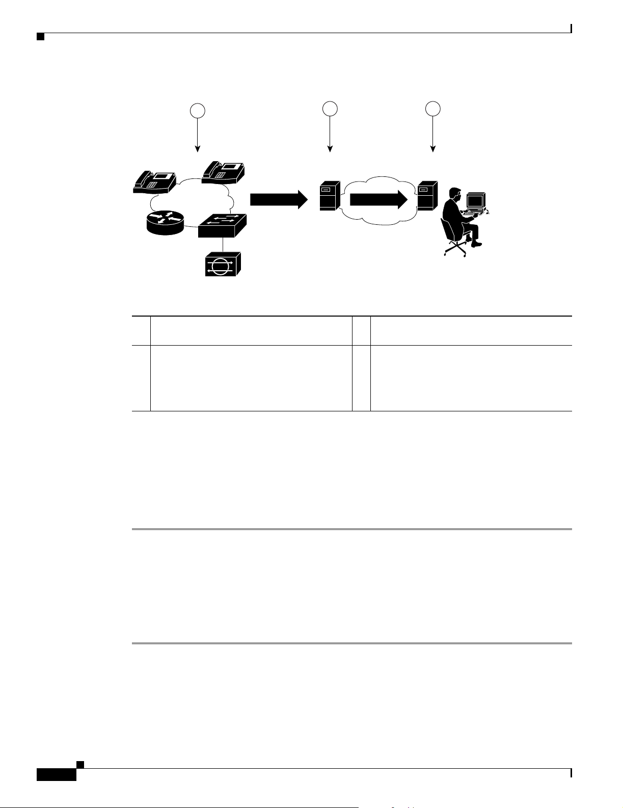
Figure 1-1 shows Service Monitor and Cisco 1040s installed with Operations Manager.
User Guide for Cisco Unified Service Monitor
1-1
Page 16
Getting Started with Service Monitor
Figure 1-1 Service Monitor Deployment
Chapter 1 Using Cisco Unified Service Monitor
1
IP
IP
Cisco 1040
2 3
Cisco Unified
Service Monitor
Cisco Unified
Operations Manager
141960
1 Cisco 1040 monitors actual voice calls. 3 Operations Manager presents alert
information.
2 Service Monitor evaluates MOS values and
— —
sends SNMP traps when a threshold is
violated. Service Monitor also sends an
SNMP trap when a Cisco 1040 is
unreachable.
For more information, see the following topics:
• Generating a Cisco 1040 Unreachable Trap, page 1-17
• MIBs Used and SNMP Traps Generated, page A-1
Starting Service Monitor
Step 1 Enter http:\\server_name:1741 into your browser, where server_name is the DNS name or the IP address
of the server where Service Monitor is installed. A login page is displayed.
Step 2 Enter admin for the User ID.
Step 3 Enter the password that you entered for the admin user during installation and press Enter. The
CiscoWorks home page appears.
Step 4 From the Cisco Unified Service Monitor pane, select Service Monitor > Service Monitor Operations.
A new window opens, displaying the Service Monitor home page.
1-2
User Guide for Cisco Unified Service Monitor
OL-9351-01
Page 17

Chapter 1 Using Cisco Unified Service Monitor
Setting Up Service Monitor
Step 1 From the Service Monitor home page, select Setup. The Setup page appears.
Step 2 Update data described in the following table.
GUI Element Description/Action
Auto Registration radio
buttons
Getting Started with Service Monitor
Select one of the following:
• Enable—As a Cisco 1040 joins the network, it automatically
registers with a Service Monitor using information provided in
the default configuration file. See Understanding Automatic
Registration and Configuration Files, page 1-8 and Editing the
Default Configuration (Automatic Registration), page 1-12.
• Disable—As a Cisco 1040 joins the network, it registers with a
Service Monitor only when you have created a configuration file
specifically for that Cisco 1040. See Adding a Cisco 1040
(Manual Registration), page 1-9.
Default value is Disable.
Note If the number of Cisco 1040s registered to Service Monitor
equals the number allowed by the license, Service Monitor
does not allow additional Cisco 1040s to register. See
Licensing Overview, page B-1.
Call Metrics Archiving radio
buttons
Select one of the following:
• Enable—After analysis, Service Monitor saves data from
Cisco 1040s to disk files.
• Disable—After analysis, Service Monitor discards data.
Default value is Disable.
Note Call metrics are archived to the directory specified when you
installed Service Monitor.
Image File Directory field Directory on the Service Monitor server where binary image files and
configuration files for the Cisco 1040 are stored. Grayed out because
you cannot edit it.
Note This directory was specified during the installation of Service
Monitor.
MOS Threshold field Enter the value below which you want Service Monitor to send an
SNMP trap. Default value is 3.5. Minimum value is 1.0; maximum
value is 5.0.
Starting Cisco 1040 Sensor ID
list and field
Accept the default initial letter in the list and enter a 3-digit number
in the field. A Cisco 1040 Sensor ID consists of a letter and a 3-digit
number, for example: A100.
Service Monitor assigns this ID to the first Cisco 1040 to register with
it and increments from this ID to assign Cisco 1040 Sensor IDs
subsequently.
TFTP Server and Port fields Enter an IP address—or a DNS name—and a port number.
OL-9351-01
User Guide for Cisco Unified Service Monitor
1-3
Page 18

Getting Started with Service Monitor
GUI Element Description/Action
Trap Forwarding Parameters
SNMP Community String Enter the SNMP community string for the trap receivers. Default is
Trap Receiver n and Port fields
(where n is a number from
1to4)
Step 3 Click OK.
Chapter 1 Using Cisco Unified Service Monitor
public.
Enter up to 4 trap receivers:
• Trap Receiver n—Enter the IP address or DNS name of a server.
To use Operations Manager to act on and display data from
Service Monitor—for example to use the Service Quality Alerts
dashboard—specify the system with Operations Manager as a
trap receiver.
• Port—Enter the port number on which the receiver listens for
SNMP traps. The default is 162; however, a different port might
be used for this purpose on this server.
Service Monitor generates SNMP traps and forwards them to these
receivers.
Copying Image and Configuration Files to the TFTP Server
When you install Service Monitor, you supply the name of the image file directory that Service Monitor
uses to store files for Cisco 1040s. Service Monitor installation creates the directory and stores the
binary image and default configuration files for Cisco 1040s in it.
To enable you to enforce security procedures that you might have in place at your site, Service Monitor
does not copy files to your TFTP server. You must manually copy binary image and configuration files
for Cisco 1040s to the TFTP server as follows:
• Cisco 1040 binary image file—The filename format is
SvcMon<vendor code><Cisco 1040 type><major version>_<minor version><bugfix version>.img.
For example:
SvcMonAA2_24.img
• Cisco 1040 configuration files—Copy configuration files after you update them as shown in the
following table.
File to copy from the image file directory to
Copy configuration files after you…
Edit the default configuration file. (If you enable
automatic registration, you must also edit the default
configuration file.)
Add a Cisco 1040 (manual registration). QOVmacaddress.CNF—Configuration
Edit the configuration file for a Cisco 1040.
the TFTP server
QOVDefault.CNF
file for the Cisco 1040 with that MAC
address.
1-4
User Guide for Cisco Unified Service Monitor
OL-9351-01
Page 19

Chapter 1 Using Cisco Unified Service Monitor
The image file directory path and TFTP server IP address are displayed on the Setup page; see Setting
Up Service Monitor, page 1-3.
Note • If you have configured multiple instances of Service Monitor to use the same TFTP server, and
automatic registration is enabled, all Cisco 1040s register to the same primary Service Monitor.
Update the configuration file for each Cisco 1040 that should register to another Service Monitor;
see Editing the Configuration for a Specific Cisco 1040, page 1-11.
• If you have configured multiple instances of Service Monitor to use multiple TFTP servers, see
Configuring Service Monitors and Cisco 1040s when Multiple TFTP Servers Are in Use, page 1-9.
Managing Cisco 1040s
Note You must configure DHCP and DNS correctly for Cisco 1040s to work properly. For more information,
see Quick Start Guide for Cisco 1040 Sensor.
Managing Cisco 1040s
The following information is available for managing Cisco 1040s:
• Understanding the Cisco 1040 Sensor Details Page, page 1-6
• Registering Cisco 1040s to Service Monitors, page 1-8
• Resetting a Cisco 1040, page 1-13
• Setting the Time on Cisco 1040s, page 1-14
• Updating Image Files on Cisco 1040s, page 1-14
• Moving a Cisco 1040, page 1-15
• Deleting a Cisco 1040, page 1-15
• Using the Cisco 1040 Web Interface, page 1-15
OL-9351-01
User Guide for Cisco Unified Service Monitor
1-5
Page 20

Managing Cisco 1040s
Understanding the Cisco 1040 Sensor Details Page
Step 1 From the Service Monitor home page, select Cisco 1040 Sensor Management. The Cisco 1040 Sensor
Details page displays information listed in the following table.
GUI Element Description/Action
Exports data from the Cisco 1040 Sensor Details page to a CSV or PDF
file. See Exporting Data to a CSV or PDF File, page 1-6.
Opens a printer-friendly version of the data in another window; for
printing from a browser window.
Check box column Select Cisco 1040s that you want to delete or reset, or on which you
want to set the time.
ID column Click the ID to launch an HTML page on the Cisco 1040. (See Using the
Cisco 1040 Web Interface, page 1-15.)
Status column Displays one of the following:
• Not Registered—Not registered to any Service Monitor.
• Registered—Registered to the primary Service Monitor.
Chapter 1 Using Cisco Unified Service Monitor
• Failover—Registered to a secondary or tertiary Service Monitor.
• Unreachable—Not responding.
Address column Displays MAC and IP addresses for Cisco 1040.
Service Monitor columns Displays both of the following:
• Assigned—IP address or hostame of the primary Service Monitor
defined for the Cisco 1040.
• Active—IP address or hostame of the Service Monitor to which the
Cisco 1040 is currently sending data. (Different from the assigned
Service Monitor only when the Cisco 1040 has failed over to a
secondary or tertiary Service Monitor.)
Last Reset Time column The last date and time the Cisco 1040 was rebooted.
Edit column Click (Edit) link to edit the Cisco 1040 configuration. See Editing the
Configuration for a Specific Cisco 1040, page 1-11.
View column Click the (View) link to view details of the Cisco 1040 configuration.
Note The Cisco 1040 Sensor Details page displays only those Cisco 1040s that are registered to the Service
Monitor up to the number specified by the license, with 50 Cisco 1040s as the uppermost limit. For more
information, see Licensing Overview, page B-1.
1-6
Exporting Data to a CSV or PDF File
After you click the export icon, a dialog box appears.
User Guide for Cisco Unified Service Monitor
OL-9351-01
Page 21

Chapter 1 Using Cisco Unified Service Monitor
Step 1 Select one radio button: CSV (comma-separated values file) or PDF.
Step 2 Browse to the location where you want to store the file and click OK.
Viewing Details for a Specific Cisco 1040
The Cisco 1040 Sensor Detail dialog box opens, displaying the Cisco 1040 Sensor Information table
described here.
Field Description/Action
Managing Cisco 1040s
Exports data from the Cisco Information table to a CSV or
PDF file. See Exporting Data to a CSV or PDF File, page 1-6.
Opens a printer-friendly version of the data in another window;
for printing from a browser window.
Opens context-sensitive online help.
ID link Cisco 1040 Sensor ID—Click to open a web interface on the
Cisco 1040. See Using the Cisco 1040 Web Interface, page
1-15.
Status Displays one of the following:
• Not Registered—Not registered to any Service Monitor.
• Registered—Registered to the primary Service Monitor.
• Failover—Registered to a secondary or tertiary Service
Monitor.
• Unreachable—Not responding.
MAC Address Cisco 1040 MAC address.
IP Address Cisco 1040 IP address.
Primary Service Monitor IP address or DNS name for the primary Service Monitor.
Secondary Service Monitor IP address or DNS name for the secondary Service Monitor;
blank if not set. (See Editing the Configuration for a Specific
Cisco 1040, page 1-11.)
Tertiary Service Monitor IP address or DNS name for the tertiary Service Monitor;
blank if not set. (See Editing the Configuration for a Specific
Cisco 1040, page 1-11.)
OL-9351-01
User Guide for Cisco Unified Service Monitor
1-7
Page 22

Managing Cisco 1040s
Field Description/Action
Image File Name Name of the image file installed on the Cisco 1040.
Note If there is a more recent image file available on the
Last Reset Time Date and time that the Cisco 1040 was last reset. (See
Resetting a Cisco 1040, page 1-13
Description User-entered description for the Cisco 1040. (See Editing the
Configuration for a Specific Cisco 1040, page 1-11.)
Registering Cisco 1040s to Service Monitors
After it is connected to a switch, a Cisco 1040 uses DHCP to obtain the IP address of the TFTP server.
The Cisco 1040 checks the TFTP server for a configuration file, using the first of the following files that
it finds:
Chapter 1 Using Cisco Unified Service Monitor
TFTP server, you must edit the configuration file for
the Cisco 1040, specifying the filename for the more
recent image, you must copy the updated configuration
file to the TFTP server, and you must reset the
Cisco 1040. (See Editing the Configuration for a
Specific Cisco 1040, page 1-11.)
• QOVmacaddress.CNF—Where MAC address is the MAC address of the Cisco 1040.
Note This configuration file is created by the automatic registration process and by adding a
Cisco 1040 manually. You must copy this configuration file to the TFTP server. For more
information, see Adding a Cisco 1040 (Manual Registration), page 1-9 and Copying Image
and Configuration Files to the TFTP Server, page 1-4.
• QOVDefault.CNF—Default configuration file; used when automatic registration is enabled on the
Service Monitor (see Setting Up Service Monitor, page 1-3.)
Note The default configuration file is installed on the server with Service Monitor. To enable a
Cisco 1040 to use this file, you must enable automatic registration, edit the default
configuration file (see Editing the Default Configuration (Automatic Registration), page
1-12), and copy it to the TFTP server (see Copying Image and Configuration Files to the
TFTP Server, page 1-4.)
Note Service Monitor continues to allow Cisco 1040s to register until the number of registered Cisco 1040s
reaches the number specified by the license. For more information, see Licensing Overview, page B-1.
Understanding Automatic Registration and Configuration Files
1-8
When automatic registration is enabled, a newly connected Cisco 1040 registers to a Service Monitor
using the default configuration file, QOVDefault.CNF. After a Cisco 1040 registers to a Service Monitor,
a configuration file QOV<MAC address>.CNF is created in the image file directory. You must copy this
User Guide for Cisco Unified Service Monitor
OL-9351-01
Page 23

Chapter 1 Using Cisco Unified Service Monitor
Managing Cisco 1040s
configuration file to the TFTP server. See Copying Image and Configuration Files to the TFTP Server,
page 1-4. Thereafter, every time that you reset the Cisco 1040, it uses QOV<MAC address>.CNF to
register to a Service Monitor.
There can be only one default configuration file on the TFTP server. The default configuration file
specifies the primary Service Monitor. Therefore, each Cisco 1040 that uses the same TFTP server
registers to the same Service Monitor.
Note When multiple Service Monitors share the same TFTP server, after automatic registration completes,
you must edit the configuration file for any Cisco 1040 that you want to register to primary, secondary,
and tertiary Service Monitors different from those listed in the default configuration file. See Editing the
Configuration for a Specific Cisco 1040, page 1-11.
Configuring Service Monitors and Cisco 1040s when Multiple TFTP Servers Are in Use
If you have multiple licensed instances of Service Monitor, you can configure them to use one TFTP
server or multiple TFTP servers. When you use multiple TFTP servers, ensure that each TFTP server
holds a current copy of the configuration file for each Cisco 1040. All QOV<macaddress>.CNF files on
each TFTP server should be fully replicated to the other TFTP servers using any file replication
mechanism.
Following this recommendation ensures that, when a Cisco 1040 fails over to a Service Monitor using a
different TFTP server, the Cisco 1040 locates and loads the specific configuration file that was created
for it. Access to the correct configuration file from any TFTP server enables the Cisco 1040 to retain its
ID while registering with a failover Service Monitor that uses a different TFTP server.
Note Copying a configuration file to a TFTP server does not cause a Cisco 1040 to load that configuration file.
A Cisco 1040 loads a configuration file from a TFTP server only during failover or reset. (See
Understanding Cisco 1040 Failover to a Secondary or Tertiary Service Monitor, page 1-13 and Resetting
a Cisco 1040, page 1-13).
Adding a Cisco 1040 (Manual Registration)
Note If automatic registration is enabled, you can still add a Cisco 1040 to Service Monitor manually before
you connect the Cisco 1040 if you want to do so.
Step 1 From the Service Monitor home page, select Cisco 1040 Sensor Management.
Step 2 Click Add. The Add a Cisco 1040 Sensor dialog box appears.
Note The number of Cisco 1040s that you can add to Service Monitor depends on the limit specified
by your license. If you already have reached the limit, an error message is displayed and you
cannot proceed. You might be able to upgrade your license to support additional Cisco 1040s.
For more information, see Licensing Overview, page B-1.
Step 3 Enter data listed in the following table.
OL-9351-01
User Guide for Cisco Unified Service Monitor
1-9
Page 24

Managing Cisco 1040s
Chapter 1 Using Cisco Unified Service Monitor
GUI Element Description/Action
Cisco 1040 Sensor ID Accept the default initial letter and enter a 3-digit number. A Cisco 1040
Sensor ID consists of a letter and a 3-digit number, for example: A100.
Note If you enter an existing Cisco 1040 Sensor ID, Service Monitor
displays an error message; in this case, you should enter a
different 3-digit number.
Image Filename Enter the binary image filename. The filename format is
SvcMng<vendor code><Cisco 1040 type><major version>_<minor
version><bugfix version>.img. For example:
SvcMonAA2_24.img
For more information, see Copying Image and Configuration Files to the
TFTP Server, page 1-4 and Updating Image Files on Cisco 1040s, page
1-14.
MAC Address Enter the MAC address for the Cisco 1040 that you are adding.
Primary Service Monitor Enter an IP address or DNS name of a host where Service Monitor is
installed. The Cisco 1040 sends data to this Service Monitor unless it
becomes unreachable.
Secondary Service Monitor (Optional.) Enter an IP address or DNS name of a host where another
instance of Service Monitor is installed. The Cisco 1040 sends data to
this Service Monitor only if the primary Service Monitor becomes
unreachable.
Tertiary Service Monitor (Optional.) Enter an IP address or DNS name of a host where another
instance of Service Monitor is installed. The Cisco 1040 sends data to
this Service Monitor only if the primary and secondary Service Monitors
become unreachable.
Description Enter up to 80 characters.
1-10
Step 4 Click OK. The configuration file is saved on the server where Service Monitor is installed. The
configuration file is named QOV<MAC address>.CNF, where <MAC address> is the MAC address for
the Cisco 1040. (To view the MAC address, see Using the Cisco 1040 Web Interface, page 1-15.)
Step 5 Copy the configuration file from the image file directory on the server where Service Monitor is installed
to the TFTP server. When you plug the Cisco 1040 in and when you reset it, it will load this configuration
file.
Note The image file directory path and the TFTP server address are displayed on the Setup page;
Setting Up Service Monitor, page 1-3.)
If you are using more than one TFTP server, see Configuring Service Monitors and Cisco 1040s when
Multiple TFTP Servers Are in Use, page 1-9.
User Guide for Cisco Unified Service Monitor
OL-9351-01
Page 25

Chapter 1 Using Cisco Unified Service Monitor
Editing the Configuration for a Specific Cisco 1040
Note Do not edit a Cisco 1040 configuration file using a text editor. Edit a Cisco 1040 configuration file using
this procedure only.
This procedure updates the configuration file for a Cisco 1040. After you edit the configuration file, you
must copy it to the TFTP server and reset the Cisco 1040.
Step 1 From the Service Monitor home page, select Cisco 1040 Sensor Management. (See Understanding the
Cisco 1040 Sensor Details Page, page 1-6.)
Step 2 Click the (Edit) link for the Cisco 1040 that you want to modify.
Step 3 Update any of the following fields.
GUI Element Description/Action
Cisco 1040 Sensor ID If you want to change the ID, accept the default initial letter and enter a
3-digit number. A Cisco 1040 Sensor ID consists of a letter and a 3-digit
number, for example: A100.
Note If you enter an existing Cisco 1040 Sensor ID, Service Monitor
displays an error message.
Image Filename Enter the binary image filename. The filename format is
SvcMon<vendor code><Cisco 1040 type><major version>_<minor
version><bugfix version>.img. For example:
SvcMonAA2_24.img
Managing Cisco 1040s
Where:
• A is the vendor code for this Cisco 1040 (for internal use)
• A is the Cisco 1040 type (for internal use)
• 2 is the major release number
• 1 is the minor release number
• 6 is the bugfix number
For more information, see Copying Image and Configuration Files to the
TFTP Server, page 1-4 and Updating Image Files on Cisco 1040s, page
1-14.
Primary Service Monitor Enter an IP address or DNS name of a host where Service Monitor is
installed. The Cisco 1040 sends data to this Service Monitor unless it
becomes unreachable.
Secondary Service Monitor (Optional.) Enter an IP address or DNS name of a host where Service
Monitor is installed. The Cisco 1040 sends data to this Service Monitor
only if the primary Service Monitor becomes unreachable.
Tertiary Service Monitor (Optional.) Enter an IP address or DNS name of a host where Service
Monitor is installed. The Cisco 1040 sends data to this Service Monitor
only if the primary and secondary Service Monitors become
unreachable.
Description Enter up to 80 characters.
OL-9351-01
User Guide for Cisco Unified Service Monitor
1-11
Page 26

Managing Cisco 1040s
Step 4 Click OK.
Step 5 Copy the configuration file from the image file directory on the server where Service Monitor is installed
to the TFTP server. When you plug the Cisco 1040 in and when you reset it, it will load this configuration
file.
Note The image file directory path and the TFTP server address are displayed on the Setup page;
Setting Up Service Monitor, page 1-3.)
If you have multiple instances of Service Monitor and they are configured to use different TFTP servers,
see Configuring Service Monitors and Cisco 1040s when Multiple TFTP Servers Are in Use, page 1-9.
Step 6 Reset the Cisco 1040; see Resetting a Cisco 1040, page 1-13.
Editing the Default Configuration (Automatic Registration)
If you edit the default configuration file, Cisco 1040s can use the information that you specify to
automatically register with a Service Monitor. Edit the default configuration file to specify the primary,
secondary, and tertiary Service Monitors and the image filename for Cisco 1040s. After you edit the file,
you must copy it to the TFTP server specified for the Service Monitor.
Chapter 1 Using Cisco Unified Service Monitor
Note Do not edit the default configuration file using a text editor. Edit the default configuration file using this
procedure only.
Step 1 From the Service Monitor home page, select Default Configuration. The Cisco 1040 Default
Configuration page appears.
Step 2 Enter information in the following fields:
• Primary Service Monitor—Enter an IP address or DNS name of a host where Service Monitor is
installed.
• Secondary Service Monitor—(Optional.) Enter an IP address or DNS name of a host where another
instance of Service Monitor is installed.
• Tertiary Service Monitor—(Optional.) Enter an IP address or DNS name of a host where another
instance of Service Monitor is installed.
• Image Filename—Enter the binary image filename. The filename format is
SvcMon<vendor code><Cisco 1040 type><major version>_<minor version><bugfix version>.img.
For example:
SvcMonAA2_24.img
Step 3 Click OK. Service Monitor saves your changes.
Step 4 Copy the default configuration file, QOVDefault.CNF, from the image file directory on the server where
Service Monitor is installed to the TFTP server.
1-12
User Guide for Cisco Unified Service Monitor
OL-9351-01
Page 27

Chapter 1 Using Cisco Unified Service Monitor
Note The image file directory path and the TFTP server address are displayed on the Setup page;
Setting Up Service Monitor, page 1-3.)
Understanding Cisco 1040 Failover to a Secondary or Tertiary Service Monitor
This topic explains how a Cisco 1040 determines that a primary Service Monitor is unreachable and how
the Cisco 1040 fails over to a secondary or tertiary Service Monitor.
A Cisco 1040 sends keepalive messages to the Service Monitor to which it is registered and receives
acknowledgements from the Service Monitor. After sending three keepalives without receiving any
acknowledgement, a Cisco 1040 starts a failover process to a secondary—or tertiary—Service Monitor:
1. The Cisco 1040 sends a keepalive to the secondary Service Monitor that is listed in its configuration
file and, upon acknowledgement, registers with that Service Monitor.
Note The Cisco 1040 retains the same ID. If you are using more than one TFTP server, see
Configuring Service Monitors and Cisco 1040s when Multiple TFTP Servers Are in Use,
page 1-9.
Managing Cisco 1040s
2. The secondary Service Monitor obtains the latest configuration file for this Cisco 1040 from the
TFTP server, registering the Cisco 1040 as a failover Cisco 1040.
3. The Cisco 1040 starts sending syslog messages to the secondary Service Monitor while continuing
to send keepalives to the primary Service Monitor to determine whether it is back up. The secondary
Service Monitor processes the syslog messages from the failed over Cisco 1040.
4. When the primary Service Monitor is back up, the Cisco 1040 unregisters from the secondary
Service Monitor and registers to the primary Service Monitor again.
Resetting a Cisco 1040
Use this procedure to boot a Cisco 1040. After a Cisco 1040 boots, it first uses DHCP to obtain the IP
address of the TFTP server. From the TFTP server, Cisco 1040 obtains a configuration file. If the
configuration file specifies a binary image file that is different from the currently installed image,
Cisco 1040 also obtains the binary image file from the TFTP server.
Step 1 From the Service Monitor home page, select Cisco 1040 Sensor Management. (See Understanding the
Cisco 1040 Sensor Details Page, page 1-6.)
Step 2 Select check boxes for the Cisco 1040s that you want to reset.
Step 3 Click Reset Cisco 1040.
OL-9351-01
User Guide for Cisco Unified Service Monitor
1-13
Page 28

Managing Cisco 1040s
Setting the Time on Cisco 1040s
Note Make sure that Windows Time service is properly configured and running on the server where Service
Monitor is installed.
This procedure takes the current time from the server where Service Monitor is installed and uses it to
set the time on each Cisco 1040 that you select.
Step 1 From the Service Monitor home page, select Cisco 1040 Sensor Management. (See Understanding the
Cisco 1040 Sensor Details Page, page 1-6.)
Step 2 Select check boxes for the Cisco 1040s for which you want to set the time.
Note If Failover is displayed in the Status column for any Cisco 1040, deselect it; you cannot set the
time on it now.
Step 3 Click Set Time.
Chapter 1 Using Cisco Unified Service Monitor
Note To set the time on a Cisco 1040 that has failed over to a secondary or tertiary Service Monitor, do one
of the following:
• Wait until the status is Registered; this indicates that the Cisco 1040 is once again managed by the
primary Service Monitor; you can set the time.
• Edit the configuration for the Cisco 1040, setting the primary Service Monitor to the active Service
Monitor; see Editing the Configuration for a Specific Cisco 1040, page 1-11. Then set the time on
the Cisco 1040.
Updating Image Files on Cisco 1040s
Step 1 When a new image file becomes available, download it from the Cisco software download site:
a. Point your browser to http://www.cisco.com.
b. Select Technical Support & Documentation > Downloads.
c. Click the link for Cisco Unified Service Monitor to see and download available images.
Step 2 Copy the image file to both of the following:
• The image file directory specified when you installed Service Monitor—Copy the image file here to
retain a local copy as a backup. For the image file directory path, see Setting Up Service Monitor,
page 1-3.)
• The TFTP server—Copy the file here to provide access to it for Cisco 1040s that are configured to
use the image. For the TFTP server address, see Setting Up Service Monitor, page 1-3.
1-14
User Guide for Cisco Unified Service Monitor
OL-9351-01
Page 29

Chapter 1 Using Cisco Unified Service Monitor
Note The image filename format is
SvcMon<vendor code><Cisco 1040 type><major version>_<minor version><bugfix
version>.img. For example, SvcMonAA2_24.img.
Step 3 Modify the configuration for each Cisco 1040, entering the new image filename; see Editing the
Configuration for a Specific Cisco 1040, page 1-11.
Moving a Cisco 1040
Step 1 (Optional.) Perform this step if you want to configure the Cisco 1040 to point to a new primary Service
Monitor. Edit the configuration file for the Cisco 1040 and copy it to the TFTP server. (See Editing the
Configuration for a Specific Cisco 1040, page 1-11.)
Step 2 Unplug Cisco 1040.
Step 3 Plug Cisco 1040 in at new location. The Cisco 1040 downloads its configuration file from the TFTP
server.
Managing Cisco 1040s
Note The Cisco 1040 retains its ID after the move.
Deleting a Cisco 1040
Step 1 Delete the configuration file for the Cisco 1040 (QOVmacaddress.CNF) from the TFTP server.
Step 2 From the Service Monitor home page, select Cisco 1040 Sensor Management. (See Understanding the
Cisco 1040 Sensor Details Page, page 1-6.)
Step 3 Select check boxes for the Cisco 1040s that you want to delete.
Step 4 Click Delete.
Using the Cisco 1040 Web Interface
To use the web interface to view the contents of the configuration file for this Cisco 1040 on the TFTP
server, see Viewing the Configuration File on the TFTP Server, page 1-16.
You can open a web interface to view the information stored on a Cisco 1040 in one of the following
ways:
• Click (View) on the Cisco 1040 Sensor Details page. See Understanding the Cisco 1040 Sensor
Details Page, page 1-6.
• Enter http://<IP address> in your browser where IP address is the address of your Cisco 1040.
The Cisco 1040 web interface displays a Device Information window with the following information:
OL-9351-01
• ID—Cisco 1040 Sensor ID.
User Guide for Cisco Unified Service Monitor
1-15
Page 30

Archiving Cisco 1040 Call Metrics
• MAC Address—Cisco 1040 MAC address.
• Time stamp—Current time on the Cisco 1040.
• Status—Status of the Cisco 1040; one of the following:
–
operational—Cisco 1040 is receiving RTP streams, analyzing data, and sending data to Service
Monitor.
–
not communicating with receiver—The Service Monitor is unreachable.
• Current Service Monitor—Name of the Service Monitor to which the Cisco 1040 is sending data;
this could be the primary, secondary, or tertiary Service Monitor.
• TFTP IP Address—TFTP server from which the Cisco 1040 downloads its binary image file and
configuration file.
• Software Version—Name of the binary image file installed on the Cisco 1040. See Updating Image
Files on Cisco 1040s, page 1-14.
• Last Updated—Last time that the configuration for the Cisco 1040 was updated on Service
Monitor. See Editing the Configuration for a Specific Cisco 1040, page 1-11.
Viewing the Configuration File on the TFTP Server
Chapter 1 Using Cisco Unified Service Monitor
Step 1 From your browser, enter http://<IP address or DNS name>/Communication where IP address is the
address of your Cisco 1040 and DNS name is the DNS name for the Cisco 1040. For example:
http://Cisco-1040-sj/Communication
Step 2 The Communication Log File window displays the following information from the configuration file on
the TFTP server for this Cisco 1040:
• Receiver—IP address or DNS name of each Service Monitor—primary, secondary, and
tertiary—defined in the configuration file, separated by semicolons.
• ID—ID of the Cisco 1040 that uses this configuration file.
• Image—Name of the binary image file that the Cisco 1040 should download and run from the TFTP
server.
• Last Updated—The last time that this configuration file was updated on the Service Monitor system.
Archiving Cisco 1040 Call Metrics
To enable or disable call metrics archiving, see Setting Up Service Monitor, page 1-3. By default, Service
Monitor does not save the data it receives from Cisco 1040s. However, if you have enabled call metrics
archiving, Service Monitor saves the data in a directory on the server. The directory is specified during
Service Monitor installation.
Service Monitor creates a new data file in this directory daily at midnight. The data filename is
QoV_YYYYMMDD.csv where YYYY is the 4-digit year, MM is the two-digit month and DD is the
two-digit day. For example, QOV_20061101.csv is a data file for November 1, 2006. Service Monitor
also backs up data files that exceed a size limit and deletes older data files; for more information, see
Managing Service Monitor Data, page 2-1.
1-16
User Guide for Cisco Unified Service Monitor
OL-9351-01
Page 31

Chapter 1 Using Cisco Unified Service Monitor
You can use the data for further analysis or you can turn archiving off. (Service Monitor does not send
the archived data to other applications.) Tab l e 1-1 lists the format for call metrics data files.
Table 1-1 Service Monitor Archived Call Metrics Data Format
Description Value
Cisco 1040 Sensor ID A Cisco 1040 Sensor ID consists of a letter and a 3-digit
Time stamp Date and time
Flag indicating actual or sampled data 0: Actual
Source device IP address IPv4 address, for example:
Destination device IP address IPv4 address, for example:
Codec of call data record 2: G711Alaw 64k
Generating a Cisco 1040 Unreachable Trap
number, for example: A100
1: Sampled
172.020.119.043
172.020.119.025
6: G722 64k
9: G7231
10: G728
11: G729
Calculated MOS score 2-digit number with an implied decimal point between the
first and second digit
Primary cause of call degradation J: Jitter
P: Packet Loss
Actual packet loss in the previous minute <numeric value>
Actual jitter, in milliseconds, in the
<numeric value>
previous minute
Note Call metrics data files remain on disk for 30 days. Service Monitor deletes them thereafter. If you would
like to save these files, you must back them up using whatever method your normally use to back up your
disk. For more information, see Managing Service Monitor Data, page 2-1.
Generating a Cisco 1040 Unreachable Trap
When a Service Monitor stops receiving keepalives from a Cisco 1040 that is registered to it, the Service
Monitor generates a Cisco 1040 Unreachable SNMP trap. The Service Monitor sends this trap to up to
four recipients. For more information, see Setting Up Service Monitor, page 1-3 and MIBs Used and
SNMP Traps Generated, page A-1.
OL-9351-01
Note If you configure Operations Manager to receive traps from Service Monitor, the Cisco 1040 Unreachable
trap is displayed on the Alerts and Events monitoring dashboard under the unidentified trap device type.
User Guide for Cisco Unified Service Monitor
1-17
Page 32

Generating a Cisco 1040 Unreachable Trap
Chapter 1 Using Cisco Unified Service Monitor
1-18
User Guide for Cisco Unified Service Monitor
OL-9351-01
Page 33

Data Management and System Administration
This section contains the following topics:
• Managing Service Monitor Data, page 2-1
• Managing Log Files, page 2-3
• Configuring Users (ACS and Non-ACS), page 2-5
• Starting and Stopping Service Monitor Processes, page 2-8
• Using SNMP to Monitor Service Monitor, page 2-8
• Changing the Hostname on the Service Monitor Server, page 2-10
• Changing the IP Address on the Service Monitor Server, page 2-13
Managing Service Monitor Data
CHA P TER
2
Cisco Unified Service Monitor (Service Monitor) receives and processes call metrics data from the
Cisco 1040s that are registered to it. Optionally, Service Monitor archives call metrics data to files in the
directory specified for that purpose at the time of installation. To enable and disable archiving, see
Setting Up Service Monitor, page 1-3.
When archiving is enabled, by default, Service Monitor does the following:
• Creates a new data file daily at midnight.
• Creates a new data file whenever the current data file size exceeds 3 MB. When a file reaches this
limit, Service Monitor does the following:
–
Backs it up—Appends .n to the filetype; for example, .csv.1, .csv2, and so on up to the limit of
50 per day.
–
Creates a new data file—Retains the original filetype: (.csv).
• Retains the data files for 30 days before deleting them. If you want to retain the data files for a longer
period, you can back up the Service Monitor data files using the same method you use to back up
your file system. (Common Services backs up the Service Monitor database only and does not
include Service Monitor data files.)
Backing Up and Restoring the Service Monitor Database
The Service Monitor database stores information about Cisco 1040 configuration.
OL-9351-01
User Guide for Cisco Unified Service Monitor
2-1
Page 34

Managing Service Monitor Data
Starting a Database Backup
Use this procedure to perform an immediate backup or a scheduled backup of the Service Monitor
database.
Step 1 Click the CiscoWorks link in the upper righthand corner of the Service Monitor home page. A new
window opens.
Step 2 In the Common Services pane, select Server > Admin > Backup, click Help, and follow the
instructions.
Restoring the Database
To restore the database, you must use the command-line interface (instructions are available in online
help) and you need to know the backup directory structure.
Step 1 Click the CiscoWorks link in the upper righthand corner of the Service Monitor home page. A new
window opens.
Chapter 2 Data Management and System Administration
Step 2 In the Common Services pane, select Server > Admin > Backup, click Help, and click the Help link to
the Restoring Data topic.
Note When you restore the database, Logging settings return to the default value. As a result, error messages
only are written to the log files. If you need additional information written to your log files to debug a
problem, reset your logging settings. See Managing Log Files and Enabling and Disabling Debugging,
page 2-4.
The backup directory structure for the Service Monitor database includes the suite name, which is qovr:
• Format—/generation_number/suite[/directory]/filename
• Example—/1/qovr/qovr.db
The backup directory structure is described in Table 2-1.
Table 2-1 Service Monitor Backup Directory Structure
Option Description Usage Notes
generationNumber Backup
For example, 1, 2, and 3, with 3 being the latest database backup.
number
suite Application,
function, or
When you perform a backup, data for all suites is backed up. The
Service Monitor application suite is qovr.
module
2-2
User Guide for Cisco Unified Service Monitor
OL-9351-01
Page 35

Chapter 2 Data Management and System Administration
Table 2-1 Service Monitor Backup Directory Structure (continued)
Option Description Usage Notes
directory What is
being stored
filename Specific file
that has been
backed up
Suite applications (if applicable).
Files include database (.db).
For Service Monitor, the following file is listed directly under
generationNumber/suite:
qovr.db
Changing the Password for the Service Monitor Database
A command line script is available to change database passwords, including the password for the Service
Monitor database, qovr.db. Instructions are available in online help.
Step 1 Click the CiscoWorks link in the upper righthand corner of the Service Monitor home page. A new
window opens.
Managing Log Files
Step 2 Click Help. The help window opens.
Step 3 Select the Index tab, scroll down to the entries for D, and select database password changes.
Managing Log Files
This section includes the following topics:
• Understanding Service Monitor Syslog Handling, page 2-3
• Maintaining the History Log File, page 2-4
• Managing Log Files and Enabling and Disabling Debugging, page 2-4
Understanding Service Monitor Syslog Handling
Service Monitor receives and processes syslog messages from Cisco 1040s. After processing syslog
messages, Service Monitor writes them to the syslog file, syslog.log, in NMSROOT\qovr.
Caution Service Monitor does not use the CWCS syslog service; do not try to start this service, and do not run
crmlog.exe. Doing so will cause Service Monitor to function incorrectly.
OL-9351-01
User Guide for Cisco Unified Service Monitor
2-3
Page 36

Chapter 2 Data Management and System Administration
Managing Log Files
Maintaining the History Log File
The history log file, ServiceMonitorHistory.log, contains records of Cisco 1040 events such as Cisco
1040 reset, configuration update, and errors. The history log file accumulates records and grows in size.
If the file becomes too large, you should rename it to enable Service Monitor to start a fresh history log
file.
Note Service Monitor does not back up the history log file. If you want to back it up, use the same method
you use to back up your file system.
Managing Log Files and Enabling and Disabling Debugging
This information is provided for troubleshooting purposes. Service Monitor log files (see Table 2-2) are
located in the NMSROOT\log\qovr directory.
Note NMSROOT is the folder where Service Monitor is installed on the server. If you selected the default
directory during installation, it is C:\Program Files\CSCOpx.
Use this procedure to increase or decrease the type—and quantity—of messages written to log files.
Step 1 From the Service Monitor home page, select Logging. The Logging: Level Configuration page appears.
Note You cannot disable logging. Service Monitor always writes error and fatal messages to
application log files.
Step 2 For each Service Monitor functional module, the Error check box is always selected; you cannot deselect
it. For a list of modules and related log files, see Ta b le 2 -2.
To set all modules to Error, which is the default logging level:
a. Click the Default button. A confirmation page is displayed.
b. Click OK.
To change the logging level for individual modules:
a. For each module that you want to change, select one (or deselect all) of the following logging levels:
• Warning—Log error messages and warning messages
• Informational—Log error, warning, and informational messages
• Debug—Log error, warning, informational, and debug message
Note Deselecting all check boxes for a module returns it to Error, the default logging level.
2-4
b. Review your changes. To cancel your changes, click the Cancel button. Otherwise, click the Apply
button. Clicking the Apply button starts immediately resetting the changed logging levels for the
Service Monitor functional modules.
User Guide for Cisco Unified Service Monitor
OL-9351-01
Page 37

Chapter 2 Data Management and System Administration
Table 2-2 lists Service Monitor log files by function or module. If you request assistance, the Technical
Assistance Center (TAC) might ask you to send them some of these log files.
Table 2-2 Service Monitor Log Files by Module
Function/Module Log Files
Data Handler DataHandler.log
Skinny Server SkinnyServer.log
User Interface QovrUI.log
Configuring Users (ACS and Non-ACS)
DataHandler_stdout.log
DataHandler_sterr.log
dhError.log
LicenseCheck.log
ServiceMonitorHistory.log
tftpmanager.log
trapgen.log
Configuring Users (ACS and Non-ACS)
What Service Monitor users can see and do is determined by their user role. There are two different
mechanisms or modes for authenticating users:
• Non-ACS—You select a supported login module to provide authentication and authorization. By
default, Common Services uses the CiscoWorks Local login module to assign roles, along with
privileges associated with those roles, as described in the Permission Report. (You can generate a
Permission Report by clicking the CiscoWorks link in the upper righthand corner of the Service
Monitor home page and selecting Common Services > Server > Reports > Permission Report >
Generate Report.) For more information, refer to Configuring Users Using Non-ACS Mode
(CiscoWorks Local Login Module), page 2-5.
• ACS—In ACS mode, authentication and authorization is provided by Cisco Secure Access Control
Server (ACS). Cisco Secure ACS specifies the privileges associated with roles; however, Cisco
Secure ACS also enables you to perform device-based filtering, so that users only see authorized
devices. To use ACS mode, Cisco Secure ACS must be installed on your network and Service
Monitor must be registered with Cisco Secure ACS. For more information, refer to Configuring
Users Using ACS Mode, page 2-6.
If Operations Manager uses ACS mode for authentication and authorization and Service Monitor is
running on the same system, Service Monitor must also use ACS mode; otherwise, Service Monitor users
will not have any permissions.
Configuring Users Using Non-ACS Mode (CiscoWorks Local Login Module)
OL-9351-01
To add a user and specify their user role using CiscoWorks Local login module, select Administration >
Add Users. After the Common Services Local User Setup window opens, click the Help button for
information on the configuration steps.
Use the Permission Report to understand how each user role relates to tasks in Service Monitor.
User Guide for Cisco Unified Service Monitor
2-5
Page 38

Configuring Users (ACS and Non-ACS)
Step 1 Click the CiscoWorks link in the upper righthand corner of the Service Monitor home page. A new
window opens.
Step 2 Select Common Services > Server > Reports > Permission Report > Generate Report.
Step 3 Scroll down until you find Cisco Unified Service Monitor.
Configuring Users Using ACS Mode
To use ACS mode for authentication and authorization, Cisco Secure ACS must be installed on your
network and Service Monitor must be registered with Cisco Secure ACS.
Step 1 Verify the AAA mode:
a. Click the CiscoWorks link in the upper righthand corner of the Service Monitor home page. A new
window appears.
b. Select Server > Security > AAA Mode Setup and check which Type radio button is selected: ACS
or Non-ACS.
Step 2 Verify whether Service Monitor is registered with Cisco Secure ACS (if ACS is selected) by logging in
to Cisco Secure ACS.
Chapter 2 Data Management and System Administration
Step 3 To modify ACS roles, refer to the Cisco Secure ACS online help (on the Cisco Secure ACS server) for
information on modifying roles.
Note If you modify Service Monitor roles using Cisco Secure ACS, your changes will be propagated
to all other instances of Service Monitor that are registered with the same Cisco Secure ACS
server.
Using Service Monitor in ACS Mode
Before performing any tasks that are mentioned here, you must ensure that you have successfully
completed configuring Cisco Secure ACS with Service Monitor. If you have installed Service Monitor
after configuring the CiscoWorks Login Module to the ACS mode, then Service Monitor users are not
granted any permissions. However, the Service Monitor application is registered to Cisco Secure ACS.
Note The System Identity Setup user, defined when you installed Service Monitor, must be added to the Cisco
Secure ACS, and this user must have Network Administrator privilege. For more information, click the
CiscoWorks link in the upper righthand corner of the Service Monitor home page and select Common
Services > Server > Security > Multi-Server Trust Management > System Identity Setup.
2-6
CiscoWorks login modules enable you to add new users using a source of authentication other than the
native mechanism (that is, the CiscoWorks Local login module). You can use the Cisco Secure ACS
server for this purpose.
User Guide for Cisco Unified Service Monitor
OL-9351-01
Page 39

Chapter 2 Data Management and System Administration
By default, the CiscoWorks Local login module authentication scheme has five roles in the ACS mode.
They are listed here from least privileged to most privileged:
Help Desk User with this role has the privileges to access network status information
Approver User with this role does not have any privileges. (Service Monitor does not
Network Operator User with this role has the privilege to perform all tasks that involve
Network Administrator User with this role has the privilege to change the network. User can also
System Administrator User with this role has the privilege to perform all system administration
Configuring Users (ACS and Non-ACS)
from the persisted data. User does not have the privilege to contact any
device or schedule a job that will reach the network.
Example: View details for Cisco 1040, setup, and default configuration.
(Cannot perform modifications.)
assign any tasks to this user role.)
collecting data from the network. User does not have write access on the
network.
Example: Set up Service Monitor, add, modify, delete Cisco 1040s.
perform Network Operator tasks.
Example: Same as Network Operator.
tasks. See the Permission Report. (Click the CiscoWorks link in the upper
righthand corner of the Service Monitor home page and select Common
Services > Server > Reports > Permission Report > Generate Report).
Example: Enable and disable debugging; set logging level.
Cisco Secure ACS allows you to modify the privileges to these roles. You can also create custom roles
and privileges that help you customize Service Monitor to best suit your business workflow and needs.
To modify the default privileges, see Cisco Secure ACS online help. (On Cisco Secure ACS, click Online
Documentation > Shared Profile Components > Command Authorization Sets.)
Modifying Roles and Privileges in Cisco Secure ACS
If another instance of Service Monitor is registered with the same Cisco Secure ACS, your instance of
Service Monitor will inherit those role settings. Furthermore, any changes you make to Service Monitor
roles will be propagated to other instances of Service Monitor through Cisco Secure ACS. If you reinstall
Service Monitor, your Cisco Secure ACS settings will automatically be applied upon Service Monitor
restart.
Step 1 Select Shared Profile Components > Cisco Unified Service Monitor and click the Service Monitor
roles that you want to modify.
Step 2 Select or deselect any of the Service Monitor tasks that suit your business workflow and needs.
Step 3 Click Submit.
OL-9351-01
User Guide for Cisco Unified Service Monitor
2-7
Page 40

Chapter 2 Data Management and System Administration
Starting and Stopping Service Monitor Processes
Starting and Stopping Service Monitor Processes
To start and stop Service Monitor processes, select the CiscoWorks link from the upper righthand corner
of the Service Monitor home page, select Common Services > Server > Admin > Processes, and click
Help for instructions. Tab le 2-3 provides a complete list of Service Monitor-related processes.
Table 2-3 Service Monitor-Related Processes
Name Description Dependency
QOVR Service Monitor server. QOVRDbMonitor
QOVRDbMonitor Service Monitor database
monitor.
QOVRDbEngine Service Monitor database. —
QOVRMultiProcLogger Service Monitor process
logging.
QOVRDbEngine
—
Using SNMP to Monitor Service Monitor
Service Monitor supports the system application MIB. This support enables you to monitor Service
Monitor using a third-party SNMP management tool, so that you can:
• Consistently monitor multiple platforms—One platform on which Service Monitor resides and one
or more on which applications in the Cisco Unified Management Suite reside.
• Assess the application health using the system application MIB, which provides the following
information:
–
Applications that Service Monitor installed.
–
Processes associated with applications and current process status.
–
Processes that ran previously and application exit state.
For MIB implementation details and sample MIB walk, see Appendix C, “Service Monitor Support for
SNMP MIBs.”
Note You cannot uninstall the MIB support; however, you can stop Windows SNMP service and set the startup
type to either Manual or Disabled. See Enabling and Disabling Windows SNMP Service, page 2-9.
Configuring Your System for SNMP Queries
To enable SNMP queries, SNMP service must be installed and enabled.
2-8
Step 1 Verify that SNMP service is installed and enabled on the server where Service Monitor is installed. See
Determining the Status of Windows SNMP Service, page 2-9.
Step 2 If you determined that SNMP service was not installed, install Windows SNMP Service; see Installing
and Uninstalling Windows SNMP Service, page 2-9.
User Guide for Cisco Unified Service Monitor
OL-9351-01
Page 41

Chapter 2 Data Management and System Administration
Determining the Status of Windows SNMP Service
Windows SNMP service is a Windows component that you can add or remove when you want to. To
enable SNMP queries against the MIB that Service Monitor supports, SNMP service must be installed
and enabled. You can verify the status of Windows SNMP service as follows.
Step 1 Open the Windows administrative tool Services window.
Step 2 Verify the following:
• SNMP Service is displayed on the Windows administrative tool Services window; if so, Windows
SNMP service is installed.
Note To install Windows SNMP service, see Installing and Uninstalling Windows SNMP Service,
page 2-9.
• SNMP Service startup type is Automatic or Manual; if so, Windows SNMP service is enabled.
Using SNMP to Monitor Service Monitor
Note To enable Windows SNMP service, see Enabling and Disabling Windows SNMP Service,
page 2-9.
Installing and Uninstalling Windows SNMP Service
Windows online help provides instructions for adding and removing Windows components, such as
Windows SNMP service. To locate the instructions, try selecting the Index tab in Windows online help
and entering a keyword or phrase, such as installing SNMP service.
To uninstall Windows SNMP service, follow instructions in Windows help for removing Windows
components.
Enabling and Disabling Windows SNMP Service
You can enable or disable Windows SNMP service using the Windows administrative tool Services. For
instructions to open the Services window, see Windows online help.
Step 1 Locate SNMP Service in the Services window. The status and startup type are displayed.
Note If SNMP Service is not displayed, Windows SNMP service is not installed; see Installing and
Uninstalling Windows SNMP Service, page 2-9.
OL-9351-01
Step 2 Right-click SNMP Service and select Properties. The SNMP Service Properties window opens:
• To disable SNMP service, set Startup Type to Disable and click OK.
• To enable SNMP service, set Startup Type to Automatic or Manual and click OK.
User Guide for Cisco Unified Service Monitor
2-9
Page 42

Changing the Hostname on the Service Monitor Server
Note To start SNMP service after you enable it, right-click SNMP Service and select Start.
Configuring Security for SNMP Queries
To improve security, the SNMP set operation is not allowed on any object ID (OID). You should also
modify the credentials for SNMP service to not use a default or well-known community string.
Note You do not need to restart SNMP service to modify credentials for it.
You can modify SNMP service credentials using the Windows administrative tool Services.
Step 1 Locate SNMP Service in the Services window
Step 2 Right-click SNMP Service and select Properties. The SNMP Service Properties window opens.
Chapter 2 Data Management and System Administration
Step 3 Select the Security tab.
Step 4 Edit the accepted community names and click OK.
.
Viewing the System Application MIB Log File
The system application MIB log file, SysAppl.log, is located on the server where Service Monitor is
installed in NMSROOT\log.
Note NMSROOT is the directory where Service Monitor is installed on your system. If you selected the
default directory during installation, it is C:\Program Files\CSCOpx.
Changing the Hostname on the Service Monitor Server
To change the hostname for the Service Monitor server, you must update several files, reboot the server,
and regenerate the self-signed security certificate. Afterward, you must update the configuration on
Service Monitor.
Changing the Hostname, Rebooting the Server, and Regenerating the Certificate
Note You will reboot the server twice during this procedure. You will also stop the daemon manager to
perform some steps.
User Guide for Cisco Unified Service Monitor
2-10
OL-9351-01
Page 43

Chapter 2 Data Management and System Administration
Step 1 Change the hostname on the server as follows:
a. Stop the daemon manager by entering the following command:
net stop crmdmgtd
b. Change the hostname at My Computer > Properties > Computer Name > Change.
c. Prevent the daemon manager service from restarting after reboot. From Control panel, or from Start,
open Services and change the startup mode to Manual for the CW2000 Daemon Manager service.
d. Reboot the server.
Step 2 Change the hostname in the md.properties file (NMSROOT\lib\classpath\md.properties).
Note NMSROOT is the directory where you installed Service Monitor. If you selected the default, it
is C:\Program Files\CSCOpx.
Step 3 Change the hostname in the following registry entries:
• HKEY_LOCAL_MACHINE\SYSTEM\CurrentControlSet.
Changing the Hostname on the Service Monitor Server
• HKEY_LOCAL_MACHINE\SOFTWARE\Cisco\Resource Manager.
Note Look for all the instances of the old hostname under these registry entries, and replace them with
the new hostname.
Step 4 Change the hostname in these files:
• regdaemon.xml (NMSROOT\MDC\etc\regdaemon.xml):
–
Note the old hostname. You will need it to complete Step 5.
–
Enter the new hostname in uppercase.
• web.xml (NMSROOT\MDC\tomcat\webapps\classic\WEB-INF\web.xml).
Step 5 Create a file, NMSROOT\conf\cmic\changehostname.info, containing the old hostname and new
hostname in uppercase in the following format:
OLDHOSTNAME:NEWHOSTNAME
Note Hostnames in this file are case-sensitive; they must be entered in uppercase; the new hostname
must exactly match the hostname entered in regdaemon.xml.
Step 6 Delete the gatekeeper.ior file from this directory:
NMSROOT\www\classpath
OL-9351-01
Step 7 If Service Monitor alone is installed on the server, skip to Step 8. If Service Monitor is installed on the
same server with Operations Manager, change all occurrences of the old hostname in the following files:
• NMSROOT\objects\vhmsmarts\local\conf\runcmd_env.sh
• NMSROOT\conf\dfm\Broker.info
Step 8 If you do not know the password for the cmf database, reset the password as follows:
a. Open a Command Prompt and go to NMSROOT\bin.
b. Enter the following command:
User Guide for Cisco Unified Service Monitor
2-11
Page 44

Changing the Hostname on the Service Monitor Server
perl dbpasswd.pl dsn=cmf npwd=newpassword
where newpassword is the new password.
Note Remember this password. You will need it to complete Step 9.
Step 9 To ensure that devices added before you changed the hostname are properly classified in Device Center,
enter the following command:
dbisqlc -c "uid=cmfDBA;pwd=dbpassword;eng=cmfEng;dsn=cmf;dbf=NMSROOT\databases\cmf\cmf.db"
-q update PIDM_app_device_map SET app_hostname=`NewhostName' where
app_hostname=`OldhostName'
where:
• dbpassword is the Common Services database password.
• NMSROOT is the directory where you installed Service Monitor.
• NewhostName is the new hostname.
• OldhostName is the old hostname.
Chapter 2 Data Management and System Administration
Step 10 From the Control panel, or from Start, open Services and change the startup mode to Automatic for the
CW2000 Daemon Manager service.
Step 11 Reboot the server.
Step 12 Replace the old hostname with the new hostname in the self-signed security certificate and regenerate it:
a. Select Common Services > Server > Security > Certificate Setup.
b. For more information, click Help.
Step 13 Reconfigure Service Monitor. See Reconfiguring Service Monitor after a Hostname Change, page 2-12.
Reconfiguring Service Monitor after a Hostname Change
You must complete this procedure after you complete the procedure Changing the Hostname, Rebooting
the Server, and Regenerating the Certificate, page 2-10.
Step 1 Change the IP address or hostname in each of the following configuration files:
• The default configuration file—See Editing the Default Configuration (Automatic Registration),
page 1-12.
• The specific configuration file for each Cisco 1040 managed by the Service Monitor—See Editing
the Configuration for a Specific Cisco 1040, page 1-11.
Step 2 Copy the updated configuration files from the Service Monitor server to the TFTP server. See Copying
Image and Configuration Files to the TFTP Server, page 1-4.
2-12
User Guide for Cisco Unified Service Monitor
OL-9351-01
Page 45

Chapter 2 Data Management and System Administration
Changing the IP Address on the Service Monitor Server
Step 3 Reset the Cisco 1040s. See Resetting a Cisco 1040, page 1-13.
Step 4 If Service Monitor is configured to send traps to Operations Manager:
• If Operations Manager is installed on the same server as Service Monitor, set up Service Monitor to
send traps to the new hostname or IP address. See Setting Up Service Monitor, page 1-3.
• If Operations Manager is installed on another server, on Operations Manager, delete the Service
Monitor and add it again. For more information, see Operations Manager online help.
Changing the IP Address on the Service Monitor Server
Step 1 Stop the daemon manager by entering the following command:
net stop crmdmgtd
Step 2 Delete the gatekeeper.ior file from this directory:
NMSROOT\www\classpath
Note NMSROOT is the folder where Service Monitor is installed on the server. If you selected the
default directory during installation, it is C:\Program Files\CSCOpx.
Step 3 Change the IP address of the Service Monitor server.
Step 4 Allow 15 minutes to elapse from the time you completed step 1, then restart the daemon manager by
entering the following command:
net start crmdmgtd
Step 5 Reconfigure Service Monitor. See Reconfiguring Service Monitor after a Hostname Change, page 2-12.
OL-9351-01
User Guide for Cisco Unified Service Monitor
2-13
Page 46

Changing the IP Address on the Service Monitor Server
Chapter 2 Data Management and System Administration
2-14
User Guide for Cisco Unified Service Monitor
OL-9351-01
Page 47

APPENDIX
A
MIBs Used and SNMP Traps Generated
MIBS Used
Service Monitor uses the CISCO-SYSLOG-MIB to generate SNMP traps.
SNMP Traps Generated
Cisco Unified Service Monitor (Service Monitor) generates the following traps:
• MOS violation
• Cisco 1040 unreachable
Trap details are provided as name-value pairs in clogHistMsgText field of the clogMessageGenerated
notification. Tab le A- 1 lists details of the MOS violation SNMP trap.
Table A-1 MOS Violation Trap Details
TAG Description Value
TT Trap type 1
01 Cisco 1040 ID <letter><3-digit numeric value less than 1000>
02 Timestamp <YYYYMMDDhhmm>
03 Threshold value 2-digit number with an implied decimal point
between the first and second digits
A Flag indicating actual or sampled data 0: Actual
OL-9351-01
1: Sampled
B Source device IP address IPv4 address, for example:
F0.F0.F0.58
C Recipient device IP address IPv4 address, for example:
F0.F0.F0.58
D Codec of call data record 2: G711Alaw 64k
6: G722 64k
9: G7231
10: G728
11: G729
E Calculated MOS score 2-digit number with an implied decimal point
between the first and second digit
User Guide for Cisco Unified Service Monitor
A-1
Page 48

Appendix A MIBs Used and SNMP Traps Generated
Table A-1 MOS Violation Trap Details (continued)
TAG Description Value
F Primary cause of call degradation J: Jitter
P: Packet Loss
G Actual packet loss in the previous minute <numeric value>
H Actual jitter in msec in the previous
minute
Table A-2 lists details of the Cisco 1040 unreachable SNMP trap.
Table A-2 Cisco 1040 Unreachable Trap Details
TAG Description Value
TT Trap type 2
01 Cisco 1040 ID <letter><3-digit numeric value less than 1000>
02 Timestamp <YYYYMMDDhhmm>
<numeric value>
A-2
User Guide for Cisco Unified Service Monitor
OL-9351-01
Page 49

Licensing
This appendix provides licensing information for Cisco Unified Service Monitor (Service Monitor). It
contains the following sections:
• Licensing Overview, page B-1
• Licensing Reminders, page B-4
Licensing Overview
Licensing ensures that you possess a licensed copy of Service Monitor and enables you to increase the
number—up to 50—of Cisco 1040s that Service Monitor supports. To determine whether Service
Monitor is licensed, see Verifying Service Monitor License Status, page B-1. If you do not have a license
or you want to ugprade your license, see Licensing Scenarios, page B-2.
APPENDIX
B
Verifying Service Monitor License Status
Use this procedure to determine the status of the Service Monitor license and the number of Cisco 1040s
that Service Monitor supports.
Step 1 Select the CiscoWorks link in the upper righthand corner of the Service Monitor home page. A new
window opens.
Step 2 Select Common Services > Server > Admin > Licensing. The Licensing Information page appears,
displaying the information in the following table.
OL-9351-01
User Guide for Cisco Unified Service Monitor
B-1
Page 50

Licensing Overview
Appendix B Licensing
Column Description
Name Abbreviated product name—For Service Monitor, this is SM.
Version Product version—A.b.c, where A is the major version number, b is
the minor version number, and c is the service pack number. For
example, SM 1.1.0 indicates version 1.1 without service packs.
Size Limit—Number of Cisco 1040s that Service Monitor supports.
Note Service Monitor supports a maximum of 50 Cisco 1040s.
Status One of the following:
• Purchased—You have a registered, licensed product.
• Evaluation—This license will expire on the expiration date;
Service Monitor will stop running.
Expiration Date Date on which Service Monitor stops running. Applies to evaluation
licenses.
Licensing Scenarios
Table B-1 describes what to do in different scenarios if you do not have a licensed, registered copy of
Service Monitor or if you want to increase device support.
Note When you purchase Service Monitor software, it comes with a PAK that enables support for up to
10 Cisco 1040 Sensors. You can purchase additional upgrade licenses in increments of 10 to support up
to 50 Cisco 1040 Sensors on a single Service Monitor server.
Table B-1 How to Obtain and Register a License
Scenario What to do
Service Monitor
included with Operations Manager
Service Monitor
standalone installation
Service Monitor
installed standalone with an evaluation
license
Service Monitor
support for additional Cisco 1040s
Moving Service Monitor to another
server
See Licensing Process, page B-3.
See Quick Start Guide for Cisco Unified Service Monitor 1.1.
Obtain a PAK and license file for the installed version of
Service Monitor to upgrade an evaluation license to a
purchased license. See Licensing Process, page B-3.
See Licensing Process, page B-3.
Note Each time you register a license for additional device
support, you license size increases correspondingly.
Call Cisco Technical Assistance Center (TAC) for assistance.
B-2
User Guide for Cisco Unified Service Monitor
OL-9351-01
Page 51

Appendix B Licensing
Licensing Process
For information on when it is appropriate to use this process, see Licensing Scenarios, page B-2. To
license Service Monitor, do the following:
1. Obtain a Product Authorization Key (PAK)—You need a PAK, along with the MAC address of the
server where you will install Service Monitor, to obtain a license file. See Obtaining a PAK, page
B-3.
2. Obtain a license file—You need a license file to register your product or upgrade on the server where
Service Monitor is installed. See Obtaining a License File, page B-3.
3. Copy the license file to the server where Service Monitor is installed and register the license file.
See Registering a License File, page B-3.
Obtaining a PAK
Obtain a PAK for… By
Service Monitor
included with Operations
Manager
Service Monitor
installed standalone
Service Monitor
support for additional
Cisco 1040s
Licensing Overview
Purchasing Service Monitor software.
Locating it on the software claim certificate that is shipped with the
Service Monitor product CD.
Purchasing one or more licenses to add support to Service Monitor
for additional Cisco 1040s up to a maximum of 50.
Note Licenses for additional device support are sold in
increments of 10. See the Cisco ordering tool for
information.
Obtaining a License File
Step 1 Enter the PAK and the MAC address of the system where Service Monitor is installed at the following
URL
http://www.cisco.com/go/license.
The license file will be e-mailed to you.
After you obtain a license file, register the license on the server where Service Monitor is installed.
Registering a License File
Step 1 Copy the license file to the Service Monitor server with read permission for casuser.
Note Service Monitor uses casuser to perform tasks that require Administrator privilege.
OL-9351-01
User Guide for Cisco Unified Service Monitor
B-3
Page 52

Licensing Reminders
Note If you copy a folder that contains the license file to the Service Monitor server, be sure to provide
read permission for casuser on the folder as well as on the license file.
Step 2 Enter the license file location:
a. Click the CiscoWorks link from the upper righthand corner of the Service Monitor home page.
b. Select Common Services > Server > Admin > Licensing. For more information, click Help.
Note If you registered a license for additional device support, the size displayed on the Licensing Information
page increases. See Verifying Service Monitor License Status, page B-1.
Licensing Reminders
Appendix B Licensing
Service Monitor provides reminders in the following circumstances:
• Evaluation Version: Before Expiry, page B-4
• License Size Exceeded, page B-4
Evaluation Version: Before Expiry
If you have installed the evaluation version of Service Monitor, you must obtain the license file from
Cisco.com before expiry of the default evaluation license. For details, see Licensing Process, page B-3.
When you start Service Monitor, a licensing reminder is displayed. Before expiry of the evaluation
license, you will see the following prompt for 1 day:
Go to Cisco.com and purchase Service Monitor
This message is displayed as an alert after you log in and try to access Service Monitor. If you fail to
upgrade your evaluation license within 1 day, access to Service Monitor functionality will be prohibited.
License Size Exceeded
Service Monitor supports only the number of Cisco 1040s specified by your license. (See Ve ri fy in g
Service Monitor License Status, page B-1.) After the number of Cisco 1040s registered to Service
Monitor matches the number specified by your license:
• If you try to add a Cisco 1040 manually, an error message is displayed and you cannot proceed.
• If automatic registration is enabled and a Cisco 1040 tries to register with Service Monitor, Service
Monitor does not allow the registration and writes error messages to the LicenseCheck.log file
located in NMSROOT\log\qovr; examples of the error messages follow:
07-Feb-2006|12:52:08.351|ERROR|LicenseCheck|Thread-3|Checking for License...
07-Feb-2006|12:52:08.507|ERROR|LicenseCheck|Thread-3|License Passed. Max count is:10
07-Feb-2006|12:55:08.570|ERROR|LicenseCheck|Thread-3|The number of sensors added to system
are:13
07-Feb-2006|12:55:08.570|ERROR|LicenseCheck|Thread-3|The maximum licensed sensor count
B-4
User Guide for Cisco Unified Service Monitor
OL-9351-01
Page 53

Appendix B Licensing
Licensing Reminders
is:10
07-Feb-2006|12:55:08.570|ERROR|LicenseCheck|Thread-3|Purchase incremental License to
support more Cisco 1040 sensors
07-Feb-2006|12:55:08.570|ERROR|LicenseCheck|Thread-3|Auto registration disabled until
space available
07-Feb-2006|12:55:08.617|ERROR|LicenseCheck|Thread-3|Due to lack of sufficient license
will drop sensor:MacAddress:001120FFCF5E
Id:A111
IPAddress:172.20.4.72
PrimaryReceiver:171.69.69.179
SecondaryReceiver:null
ImageFileName:null
LastResetTime:1139345651898
Status:Registered
Description:null
07-Feb-2006|12:55:08.648|ERROR|LicenseCheck|Thread-3|Due to lack of sufficient license
will drop sensor:MacAddress:001120FFCF5C
Id:A112
IPAddress:172.20.4.66
PrimaryReceiver:171.69.69.179
SecondaryReceiver:null
ImageFileName:null
LastResetTime:1139345654757
Status:Registered
Description:null
07-Feb-2006|12:55:08.679|ERROR|LicenseCheck|Thread-3|Due to lack of sufficient license
will drop sensor:MacAddress:001120FFCF64
Id:A113
IPAddress:172.20.4.73
PrimaryReceiver:171.69.69.179
SecondaryReceiver:null
ImageFileName:null
LastResetTime:1139345659867
Status:Registered
Description:null
OL-9351-01
User Guide for Cisco Unified Service Monitor
B-5
Page 54

Licensing Reminders
Appendix B Licensing
B-6
User Guide for Cisco Unified Service Monitor
OL-9351-01
Page 55

Service Monitor Support for SNMP MIBs
Service Monitor implements the system application MIB using SNMP v2 and supplies an an SNMP
subagent. You can use simple SNMP queries to monitor the health of applications in the Cisco Unified
Communications Management suite that supports the MIBs.
For information about configuring your system to use SNMP to manage Service Monitor and other Cisco
Unified applications, see Using SNMP to Monitor Service Monitor, page 2-8.
System Application MIB Implementation
The system application MIB, defined in RFC 2287, provides applications installed, processes running
for an application, and past run information. You can use the information in the system application MIB
to determine the overall health of Service Monitor and drill down to the actual processes running for the
application.
For more information about the system application MIB, you can browse MIB information at the
following URL:
http://www.cisco.com/cgi-bin/Support/Mibbrowser/mibinfo.pl?tab=4
For an example of the data stored in this MIB, see the Sample MIB Walk for System Application MIB,
page C-8.
APPENDIX
C
System Application Resource MIB Tables
This section describes MIB tables that contain the following information:
• Installed Packages, page C-2
• Installed Elements, page C-2
• Package Status Information, page C-3
• Element Status Information, page C-4
• Status of Packages When They Ran Previously, page C-5
• Status of Elements When They Ran Previously, page C-5
• Process Map, page C-7
• Scalar Variables, page C-6
OL-9351-01
User Guide for Cisco Unified Service Monitor
C-1
Page 56

Appendix C Service Monitor Support for SNMP MIBs
System Application MIB Implementation
Installed Packages
Table C-1 stores information for installed packages for Service Monitor and other applications in the
Cisco Unified Management Suite that support the system application MIB.
Table C-1 sysApplInstallPkgTable
MIB Row Entry Description from the MIB
sysApplInstallPkgIndex Part of the index for this table. An integer used
only for indexing purposes. Generally
monotonically increasing from 1 as new
applications are installed.
sysApplInstallPkgManufacturer The manufacturer of the software application
package.
sysApplInstallPkgProductName The name assigned to the software application
package by the manufacturer.
sysApplInstallPkgVersion The version number assigned to the application
package by the manufacturer of the software.
sysApplInstallPkgSerialNumber The serial number of the software assigned by
the manufacturer.
sysApplInstallPkgDate The date and time this software application was
installed on the host.
sysApplInstallPkgLocation The complete pathname where the application
package is installed.
Cisco Unified Communications
Management Suite Usage
Running number for each application
registered with the SNMP subagent.
Cisco Systems, Inc.
Name provided when the application
was registered with the SNMP
subagent, such as Cisco Unified Service
Monitor 1.0.
Note Use this name to select an
application to watch.
Version number such as 1.0.2, where 1
is the major version, 0 is the minor
version, and 2 is the patch version or
incremental device update (IDU)
number.
“n/a”
—
NMSROOT—Directory where Service
Monitor is installed. If you selected the
default directory during installation, it
is C:\Program~1\CSCOpx.
Installed Elements
User Guide for Cisco Unified Service Monitor
C-2
For each entry in the installed packages table, Table C-1 , there can be many entries in the installed
element table, Table C-2. The number of installed elements for a package corresponds to the number of
processes being monitored for that package.
Table C-2 lists the contents of sysApplInstallElmtTable.
OL-9351-01
Page 57

Appendix C Service Monitor Support for SNMP MIBs
System Application MIB Implementation
Table C-2 sysApplInstallElmtTable
Cisco Unified Communications
MIB Row Entry Description from the MIB
sysApplInstallPkgIndex Part of the index for this table. This value identifies
the installed software package for the application of
which this process is a part.
sysApplInstallElmtIndex Unique number across the applications. Running number.
sysApplInstallElmtName The name assigned to the software element package
by the manufacturer.
sysApplInstallElmtType The type of element that is part of the installed
application.
sysApplInstallElmtDate The date and time that this component was installed
on the system.
sysApplInstallElmtPath Install location for this application NMSROOT—Directory where
sysApplInstallInstallElmt
The installed file size in 2
32
byte blocks. Default 0 (not implemented).
SizeHigh
sysApplInstallInstallElmt
The installed file size in 2
32
byte blocks. Default 0 (not implemented).
SizeLow
sysApplInstallElmtRole An operator-assigned value used in the determination
of application status.
Management Suite Usage
Value from
sysApplInstallPkgTable,
Table C-1.
Process name used in the daemon
manager (not a file or executable
name as specified in RFC 2287).
Default application(5).
Note All dates and times are
formatted using SNMPv2
textual conventions.
Service Monitor is installed. If you
selected the default directory
during installation, it is
C:\Program~1\CSCOpx.
Value used in determining
application status:
• required(3)—Process that
must run for the application to
be considered running.
sysApplInstallElmtModifyDate The date and time that this element was last modified.
sysApplInstallCurSizeHigh The current file size in 2
sysApplInstallCurSizeLow The current file size in 2
32
byte blocks. Default 0 (not implemented).
32
byte blocks. Default 0 (not implemented).
Package Status Information
Table C-3 supplies current application status for Service Monitor and other applications in the Cisco
Unified Management Suite that support the system application MIB.
User Guide for Cisco Unified Service Monitor
OL-9351-01
• unknown(5)—Optional
process.
Note All dates and times are
formatted using SNMPv2
textual conventions.
C-3
Page 58

Appendix C Service Monitor Support for SNMP MIBs
System Application MIB Implementation
Table C-3 sysApplRunTable
MIB Row Entry Description from the MIB
sysApplInstallPkgIndex Part of the index for this table. This value identifies
the installed software package for the application of
which this process is a part.
sysApplRunIndex Part of the index for this table. An arbitrary integer
used only for indexing purposes. Generally,
monotonically increasing from 1 as new applications
are started on the host, it uniquely identifies
application invocations.
sysApplRunStarted The date and time that the application was started.
sysApplRunCurrentState The current state of the running application instance.
The possible values are running(1), runnable(2) but
waiting for a resource such as CPU, waiting(3) for an
event, exiting(4), or other(5).
Cisco Unified Communications
Management Suite Usage
Value from
sysApplInstallPkgTable,
Table C-1.
Running number.
Note All dates and times are
formatted using SNMPv2
textual conventions.
This value is the measure of
application health:
• running(1)—All required
processes are running.
Element Status Information
Table C-4 provides current status for processes that belong to each application that is currently running.
Table C-4 sysApplElmtRunTable
MIB Row Entry Description from the MIB
sysApplElmtRunInstallPkg Part of the index for this table. This value identifies
the installed software package for the application of
which this process is a part.
sysApplElmtRunInvocID Part of the index for this table. This value identifies
the invocation of an application of which this process
is a part.
sysApplElmtRunIndex Part of the index for this table. A unique value for
each process running on the host.
• other(5)–One or more
required processes are not
running.
When all required processes stop
or the daemon manager stops, this
entry moves to the
sysApplPastRun table.
Cisco Unified Communications
Management Suite Usage
Value from
sysApplInstallPkgTable,
Table C-1.
Default 0.
Note Service Monitor processes
run independently and are
not invoked by any other
process.
Process ID in the operating
system.
C-4
User Guide for Cisco Unified Service Monitor
OL-9351-01
Page 59

Appendix C Service Monitor Support for SNMP MIBs
System Application MIB Implementation
Table C-4 sysApplElmtRunTable (continued)
Cisco Unified Communications
MIB Row Entry Description from the MIB
sysApplElmtRunInstallID Part of the index for this table. The value of this object
is the same value as sysApplInstallElmtIndex for the
application element of which this entry represents a
running instance.
sysApplElmtRunTimeStarted The time the process was started. —
sysApplElmtRunState The current state of the running process. The possible
values are running(1), runnable(2) but waiting for a
resource such as CPU, waiting(3) for an event,
exiting(4), or other(5).
sysApplElmtRunName The full path and filename of the process. —
sysApplElmtRunParameters The starting parameters for the process. —
sysApplElmtRunCPU Hundredths of a second of the total system CPU
resources consumed by this process.
sysApplElmtRunMemory The total amount of real system memory, measured in
kilobytes, currently allocated to this process.
sysApplElmtRunNumFiles The number of regular files that the process currently
has open.
sysApplElmtRunUser The process owner's login name. Either casuser or SYSTEM.
Management Suite Usage
Value from
sysApplInstallElmtTable,
Table C-2.
If all processes are running
successfully, value is running(1).
Note If the process terminates,
the process entry moves to
the sysElmtPastRun table.
Obtained from the operating
system.
Obtained from the operating
system.
Default 0 (not implemented).
Status of Packages When They Ran Previously
Table C-5 contains the status of applications when they ran previously.
Table C-5 sysApplPastRunTable
MIB Row Entry Description from the MIB
sysApplInstallPkgIndex Value from sysApplInstallPkgTable, Table C-1.
sysApplPastRunIndex Part of the index for this table. An arbitrary integer used only for indexing purposes.
Generally monotonically increasing from 1 as new applications are started on the host, it
uniquely identifies application invocations.
sysApplPastRunStarted The date and time that the application started.
Note All dates and times are formatted using SNMPv2 textual conventions.
sysApplPastExitState The state of the application instance when it was terminated.
sysApplPastRunEnded The date and time the application instance was determined to be no longer running.
Note All dates and times are formatted using SNMPv2 textual conventions.
Status of Elements When They Ran Previously
Table C-6 contains the status of processes when they ran previously.
OL-9351-01
User Guide for Cisco Unified Service Monitor
C-5
Page 60

Appendix C Service Monitor Support for SNMP MIBs
System Application MIB Implementation
Table C-6 sysApplElmtPastRunTable
MIB Row Entry Description from the MIB
sysApplElmtPastRunInvocID Part of the index for this table. Identifies the invocation of an application of which
this process is a part.
sysApplElmtPastRunIndex Part of the index for this table. A unique value for each process running on the host.
sysApplElmtPastRunInstallID Part of the index for this table. The value of this object is the same value as the
sysApplInstallElmtIndex for the application element of which this entry represents
a running instance.
sysApplElmtPastRunTimeStarted The time the process was started.
sysApplElmtPastRunTimeEnded The time the process was ended.
sysApplElmtPastRunName The full path and filename of the process.
sysApplElmtPastRunParameters The starting parameters for the process.
sysApplElmtPastRunCPU The last known number of hundredths of a second of the total system CPU resources
consumed by this process.
sysApplElmtPastRunMemory The last known total amount of real system memory, measured in kilobytes,
allocated to this process before it terminated.
sysApplElmtPastRunNumFiles The number of regular files that the process currently has open.
sysApplElmtPastRunUser The process owner's login name.
Scalar Variables
These variables are used to control MIB table size. You cannot update them.
Table C-7 Scalars
MIB Row Entry Description from the MIB Default Value
sysApplPastRunMaxRows Maximum number of entries allowed in the sysApplPastRun table. 2000
sysApplPastRunTableRemItems Counter for entries removed from the sysApplPastRun table after
the maximum number (sysApplPastRunMaxRows) of entries are
exceeded.
sysApplPastRunTblTimeLimit Maximum time that an entry in the sysApplPastRun table can exist
before being removed.
sysApplElemPastRunMaxRows Maximum number of entries allowed in the
sysApplElmtPastRuntable.
sysApplElemPastRunTableRemItems Counter for entries removed from the sysApplElmtPastRun table
after the maximum number (sysApplElemPastRunMaxRows) of
entries are exceeded.
SysApplElemPastRunTblTimeLimit Maximum time that an entry in the sysApplElmtPastRunTable can
exist before being removed.
sysApplAgentPollInterval Minimum interval at which polling to obtain the status of the
managed resources occurs.
20 entries
86400 seconds
(1 day)
2000 entries
20 entries
86400 seconds
(1 day)
60 seconds
C-6
User Guide for Cisco Unified Service Monitor
OL-9351-01
Page 61

Appendix C Service Monitor Support for SNMP MIBs
System Application MIB Implementation
Process Map
The sysApplMapTable contains one entry for each process currently running on the system. Tab l e C- 8
provides the index mapping from a process identifier to the invoked application, installed element, and
installed application package.
Table C-8 sysApplMapTable
MIB Row Entry Description from the MIB
sysApplElmtRunIndex Process identification number.
sysApplElmtRunInvocID Invoked application (sysApplRunIndex).
sysApplMapInstallElmtIndex Installed element (sysApplInstallElmtIndex).
sysApplMapInstallPkgIndex Installed application package (sysApplInstallPkgIndex).
OL-9351-01
User Guide for Cisco Unified Service Monitor
C-7
Page 62

System Application MIB Implementation
Sample MIB Walk for System Application MIB
This example shows abridged output from a MIB walk of the SYS-APPL-MIB on a system where Cisco
Unified Operations Manager and Service Monitor are installed.
***** SNMP QUERY STARTED *****
1: sysApplInstallPkgManufacturer.1 (octet string) Copyright (c) 2004 by Cisco Systems,
Inc.
[43.6F.70.79.72.69.67.68.74.20.28.63.29.20.32.30.30.34.20.62.79.20.43.69.73.63.6F.20.5
3.79.73.74.65.6D.73.2C.20.49.6E.63.2E (hex)]
2: sysApplInstallPkgManufacturer.2 (octet string) Copyright (c) 2004 by Cisco Systems,
Inc.
[43.6F.70.79.72.69.67.68.74.20.28.63.29.20.32.30.30.34.20.62.79.20.43.69.73.63.6F.20.5
3.79.73.74.65.6D.73.2C.20.49.6E.63.2E (hex)]
3: sysApplInstallPkgProductName.1 (octet string) Cisco Unified Service Monitor
[49.50.20.43.6F.6D.6D.75.6E.69.63.61.74.69.6F.6E.73.20.53.65.72.76.69.63.65.20.4D.6F.6
E.69.74.6F.72 (hex)]
4: sysApplInstallPkgProductName.2 (octet string) Cisco Unified Operations Manager
[49.50.20.43.6F.6D.6D.75.6E.69.63.61.74.69.6F.6E.73.20.4F.70.65.72.61.74.69.6F.6E.73.2
0.4D.61.6E.61.67.65.72 (hex)]
5: sysApplInstallPkgVersion.1 (octet string) 1.0.0 [31.2E.30.2E.30 (hex)]
6: sysApplInstallPkgVersion.2 (octet string) 2.0.0 [32.2E.30.2E.30 (hex)]
7: sysApplInstallPkgSerialNumber.1 (octet string) n/a [6E.2F.61 (hex)]
8: sysApplInstallPkgSerialNumber.2 (octet string) n/a [6E.2F.61 (hex)]
9: sysApplInstallPkgDate.1 (octet string) 2005-8-30,21:18:32 [07.D5.08.1E.15.12.20 (hex)]
10: sysApplInstallPkgDate.2 (octet string) 2005-8-30,21:18:32 [07.D5.08.1E.15.12.20 (hex)]
11: sysApplInstallPkgLocation.1 (octet string) D:\PROGRA~1\CSCOpx
[44.3A.5C.50.52.4F.47.52.41.7E.31.5C.43.53.43.4F.70.78 (hex)]
12: sysApplInstallPkgLocation.2 (octet string) D:\PROGRA~1\CSCOpx
[44.3A.5C.50.52.4F.47.52.41.7E.31.5C.43.53.43.4F.70.78 (hex)]
13: sysApplInstallElmtName.1.1 (octet string) QOVR [51.4F.56.52 (hex)]
14: sysApplInstallElmtName.1.2 (octet string) QOVRDbEngine
[51.4F.56.52.44.62.45.6E.67.69.6E.65 (hex)]
15: sysApplInstallElmtName.1.3 (octet string) QOVRDbMonitor
[51.4F.56.52.44.62.4D.6F.6E.69.74.6F.72 (hex)]
16: sysApplInstallElmtName.1.4 (octet string) Apache [41.70.61.63.68.65 (hex)]
17: sysApplInstallElmtName.1.5 (octet string) CmfDbEngine
[43.6D.66.44.62.45.6E.67.69.6E.65 (hex)]
18: sysApplInstallElmtName.1.6 (octet string) JRunProxyServer
[4A.52.75.6E.50.72.6F.78.79.53.65.72.76.65.72 (hex)]
19: sysApplInstallElmtName.1.7 (octet string) Tomcat [54.6F.6D.63.61.74 (hex)]
20: sysApplInstallElmtName.1.8 (octet string) WebServer [57.65.62.53.65.72.76.65.72 (hex)]
21: sysApplInstallElmtName.2.9 (octet string) AdapterServer
[41.64.61.70.74.65.72.53.65.72.76.65.72 (hex)]
22: sysApplInstallElmtName.2.10 (octet string) Apache [41.70.61.63.68.65 (hex)]
23: sysApplInstallElmtName.2.11 (octet string) CmfDbEngine
[43.6D.66.44.62.45.6E.67.69.6E.65 (hex)]
24: sysApplInstallElmtName.2.12 (octet string) DCRServer [44.43.52.53.65.72.76.65.72
(hex)]
25: sysApplInstallElmtName.2.13 (octet string) DfmBroker [44.66.6D.42.72.6F.6B.65.72
(hex)]
26: sysApplInstallElmtName.2.14 (octet string) DfmServer [44.66.6D.53.65.72.76.65.72
(hex)]
27: sysApplInstallElmtName.2.15 (octet string) EDS [45.44.53 (hex)]
28: sysApplInstallElmtName.2.16 (octet string) EPMDbEngine
[45.50.4D.44.62.45.6E.67.69.6E.65 (hex)]
29: sysApplInstallElmtName.2.17 (octet string) EPMServer [45.50.4D.53.65.72.76.65.72
(hex)]
30: sysApplInstallElmtName.2.18 (octet string) ESS [45.53.53 (hex)]
31: sysApplInstallElmtName.2.19 (octet string) FHDbEngine [46.48.44.62.45.6E.67.69.6E.65
(hex)]
32: sysApplInstallElmtName.2.20 (octet string) FHServer [46.48.53.65.72.76.65.72 (hex)]
Appendix C Service Monitor Support for SNMP MIBs
C-8
User Guide for Cisco Unified Service Monitor
OL-9351-01
Page 63

Appendix C Service Monitor Support for SNMP MIBs
33: sysApplInstallElmtName.2.21 (octet string) GPF [47.50.46 (hex)]
34: sysApplInstallElmtName.2.22 (octet string) INVDbEngine
[49.4E.56.44.62.45.6E.67.69.6E.65 (hex)]
35: sysApplInstallElmtName.2.23 (octet string) IVR [49.56.52 (hex)]
36: sysApplInstallElmtName.2.24 (octet string) IPIUDbEngine
[49.50.49.55.44.62.45.6E.67.69.6E.65 (hex)]
37: sysApplInstallElmtName.2.25 (octet string) IPSLAServer
[49.50.53.4C.41.53.65.72.76.65.72 (hex)]
38: sysApplInstallElmtName.2.26 (octet string) ITMDiagServer
[49.54.4D.44.69.61.67.53.65.72.76.65.72 (hex)]
39: sysApplInstallElmtName.2.27 (octet string) Interactor [49.6E.74.65.72.61.63.74.6F.72
(hex)]
40: sysApplInstallElmtName.2.28 (octet string) InventoryCollector
[49.6E.76.65.6E.74.6F.72.79.43.6F.6C.6C.65.63.74.6F.72 (hex)]
41: sysApplInstallElmtName.2.29 (octet string) IPIUDataServer
[49.50.49.55.44.61.74.61.53.65.72.76.65.72 (hex)]
42: sysApplInstallElmtName.2.30 (octet string) ITMOGSServer
[49.54.4D.4F.47.53.53.65.72.76.65.72 (hex)]
43: sysApplInstallElmtName.2.31 (octet string) jrm [6A.72.6D (hex)]
44: sysApplInstallElmtName.2.32 (octet string) LicenseServer
[4C.69.63.65.6E.73.65.53.65.72.76.65.72 (hex)]
45: sysApplInstallElmtName.2.33 (octet string) NOTSServer [4E.4F.54.53.53.65.72.76.65.72
(hex)]
46: sysApplInstallElmtName.2.34 (octet string) PTMServer [50.54.4D.53.65.72.76.65.72
(hex)]
47: sysApplInstallElmtName.2.35 (octet string) PIFServer [50.49.46.53.65.72.76.65.72
(hex)]
48: sysApplInstallElmtName.2.36 (octet string) QoVMServer [51.6F.56.4D.53.65.72.76.65.72
(hex)]
49: sysApplInstallElmtName.2.37 (octet string) SRSTServer [53.52.53.54.53.65.72.76.65.72
(hex)]
50: sysApplInstallElmtName.2.38 (octet string) SIRServer [53.49.52.53.65.72.76.65.72
(hex)]
51: sysApplInstallElmtName.2.39 (octet string) STServer [53.54.53.65.72.76.65.72 (hex)]
52: sysApplInstallElmtName.2.40 (octet string) Tomcat [54.6F.6D.63.61.74 (hex)]
53: sysApplInstallElmtName.2.41 (octet string) TISServer [54.49.53.53.65.72.76.65.72
(hex)]
54: sysApplInstallElmtName.2.42 (octet string) TopoServer [54.6F.70.6F.53.65.72.76.65.72
(hex)]
55: sysApplInstallElmtName.2.43 (octet string) VsmServer [56.73.6D.53.65.72.76.65.72
(hex)]
56: sysApplInstallElmtName.2.44 (octet string) VHMIntegrator
[56.48.4D.49.6E.74.65.67.72.61.74.6F.72 (hex)]
57: sysApplInstallElmtName.2.45 (octet string) VHMServer [56.48.4D.53.65.72.76.65.72
(hex)]
58: sysApplInstallElmtName.2.46 (octet string) ITMCTMStartup
[49.54.4D.43.54.4D.53.74.61.72.74.75.70 (hex)]
59: sysApplInstallElmtName.2.47 (octet string) IPSLAPurgeTask
[49.50.53.4C.41.50.75.72.67.65.54.61.73.6B (hex)]
60: sysApplInstallElmtName.2.48 (octet string) GpfPurgeTask
[47.70.66.50.75.72.67.65.54.61.73.6B (hex)]
61: sysApplInstallElmtName.2.49 (octet string) FHPurgeTask
[46.48.50.75.72.67.65.54.61.73.6B (hex)]
62: sysApplInstallElmtType.1.1 (integer) application(5)
System Application MIB Implementation
OL-9351-01
111: sysApplInstallElmtDate.1.1 (octet string) 2005-8-30,21:18:32 [07.D5.08.1E.15.12.20
(hex)]
112: sysApplInstallElmtDate.1.2 (octet string) 2005-8-30,21:18:32 [07.D5.08.1E.15.12.20
(hex)]
160: sysApplInstallElmtPath.1.1 (octet string) D:\PROGRA~1\CSCOpx
[44.3A.5C.50.52.4F.47.52.41.7E.31.5C.43.53.43.4F.70.78 (hex)]
User Guide for Cisco Unified Service Monitor
C-9
Page 64

System Application MIB Implementation
209: sysApplInstallElmtSizeHigh.1.1 (integer) 0
258: sysApplInstallElmtSizeLow.1.1 (integer) 0
307: sysApplInstallElmtRole.1.1 (integer) required(3)
356: sysApplInstallElmtModifyDate.1.1 (octet string) 2005-8-30,21:18:32
[07.D5.08.1E.15.12.20 (hex)]
357: sysApplInstallElmtModifyDate.1.2 (octet string) 2005-8-30,21:18:32
[07.D5.08.1E.15.12.20 (hex)]
405: sysApplInstallElmtCurSizeHigh.1.1 (integer) 0
454: sysApplInstallElmtCurSizeLow.1.1 (integer) 0
503: sysApplRunStarted.1.4 (octet string) 2005-9-27,15:51:53 [07.D5.09.1B.0F.33.35 (hex)]
505: sysApplRunCurrentState.1.4 (integer) running(1)
507: sysApplPastRunStarted.1.2 (octet string) 2005-9-27,14:43:4 [07.D5.09.1B.0E.2B.04
(hex)]
509: sysApplPastRunExitState.1.2 (integer) complete(1)
Appendix C Service Monitor Support for SNMP MIBs
511: sysApplPastRunTimeEnded.1.2 (octet string) 2005-9-27,15:43:42 [07.D5.09.1B.0F.2B.2A
(hex)]
513: sysApplElmtRunInstallID.0.0.2468 (integer) 0
569: sysApplElmtRunTimeStarted.0.0.2468 (octet string) 2005-9-27,15:54:12
[07.D5.09.1B.0F.36.0C (hex)]
625: sysApplElmtRunState.0.0.2468 (integer) running(1)
681: sysApplElmtRunName.0.0.2468 (octet string) D:\PROGRA~1\CSCOpx\bin\cwjava.exe
[44.3A.5C.50.52.4F.47.52.41.7E.31.5C.43.53.43.4F.70.78.5C.62.69.6E.5C.63.77.6A.61.76.6
1.2E.65.78.65 (hex)]
737: sysApplElmtRunParameters.0.0.2468 (octet string) -DNMSROOT=D:\PROGRA~1\CSCOpx -cp:a
lib\classpath\servlet.jar -Dvbroker.agent.port=42342
com.inprise.vbroker.gatekeeper.GateKeeper -props
D:\PROGRA~1\CSCOpx\lib\vbroker\gatekeeper.cfg
[2D.44.4E.4D.53.52.4F.4F.54.3D.44.3A.5C.50.52.4F.47.52.41.7E.31.5C.43.53.43.4F.70.78.2
0.2D.63.70.3A.61.20.6C.69.62.5C.63.6C.61.73.73.70.61.74.68.5C.73.65.72.76.6C.65.74.2E.
6A.61.72.20.2D.44.76.62.72.6F.6B.65.72.2E.61.67.65.6E.74.2E.70.6F.72.74.3D.34.32.33.34
.32.20.63.6F.6D.2E.69.6E.70.72.69.73.65.2E.76.62.72.6F.6B.65.72.2E.67.61.74.65.6B.65.6
5.70.65.72.2E.47.61.74.65.4B.65.65.70.65.72.20.2D.70.72.6F.70.73.20.44.3A.5C.50.52.4F.
47.52.41.7E.31.5C.43.53.43.4F.70.78.5C.6C.69.62.5C.76.62.72.6F.6B.65.72.5C.67.61.74.65
.6B.65.65.70.65.72.2E.63.66.67 (hex)]
793: sysApplElmtRunCPU.0.0.2468 (timeticks) 0 days 00h:00m:03s.33th (333)
849: sysApplElmtRunMemory.0.0.2468 (integer) 4716
905: sysApplElmtRunNumFiles.0.0.2468 (integer) 0
C-10
961: sysApplElmtRunUser.0.0.2468 (octet string) casuser [63.61.73.75.73.65.72 (hex)]
1017: sysApplElmtPastRunInstallID.0.0.1132 (integer) 0
1064: sysApplElmtPastRunTimeStarted.0.0.1132 (octet string) 2005-9-27,14:43:45
[07.D5.09.1B.0E.2B.2D (hex)]
User Guide for Cisco Unified Service Monitor
OL-9351-01
Page 65

Appendix C Service Monitor Support for SNMP MIBs
1111: sysApplElmtPastRunTimeEnded.0.0.1132 (octet string) 2005-9-27,15:43:42
[07.D5.09.1B.0F.2B.2A (hex)]
1158: sysApplElmtPastRunName.0.0.1132 (octet string) D:\PROGRA~1\CSCOpx\bin\cwjava.exe
[44.3A.5C.50.52.4F.47.52.41.7E.31.5C.43.53.43.4F.70.78.5C.62.69.6E.5C.63.77.6A.61.76.6
1.2E.65.78.65 (hex)]
1206: sysApplElmtPastRunParameters.0.0.2060 (octet string) itemIpiu -app IPIUDbMonitor
-dbserver IPIUDbEngine -sleep 1200 -error 90 -retry 10 -sterror 10 -stretry 5
[69.74.65.6D.49.70.69.75.20.2D.61.70.70.20.49.50.49.55.44.62.4D.6F.6E.69.74.6F.72.20.2
D.64.62.73.65.72.76.65.72.20.49.50.49.55.44.62.45.6E.67.69.6E.65.20.2D.73.6C.65.65.70.
20.31.32.30.30.20.2D.65.72.72.6F.72.20.39.30.20.2D.72.65.74.72.79.20.31.30.20.2D.73.74
.65.72.72.6F.72.20.31.30.20.2D.73.74.72.65.74.72.79.20.35 (hex)]
1252: sysApplElmtPastRunCPU.0.0.1132 (timeticks) 0 days 00h:00m:00s.26th (26)
1299: sysApplElmtPastRunMemory.0.0.1132 (integer) 7488
1346: sysApplElmtPastRunNumFiles.0.0.1132 (integer) 0
1393: sysApplElmtPastRunUser.0.0.1132 (octet string) casuser [63.61.73.75.73.65.72 (hex)]
1440: sysApplPastRunMaxRows.0 (integer) 2000
1441: sysApplPastRunTableRemItems.0 (integer) 20
1442: sysApplPastRunTblTimeLimit.0 (integer) 86400
1443: sysApplElemPastRunMaxRows.0 (integer) 2000
1444: sysApplElemPastRunTableRemItems.0 (integer) 20
1445: sysApplElemPastRunTblTimeLimit.0 (integer) 86400
1446: sysApplAgentPollInterval.0 (integer) 60
1447: sysApplMap.2.752.0.1 (integer) 1
System Application MIB Implementation
1502: sysApplMap.2.10596.0.9 (integer) 2
***** SNMP QUERY FINISHED *****
OL-9351-01
User Guide for Cisco Unified Service Monitor
C-11
Page 66

System Application MIB Implementation
Appendix C Service Monitor Support for SNMP MIBs
C-12
User Guide for Cisco Unified Service Monitor
OL-9351-01
Page 67

Configuring Service Monitor with
Cisco Secure ACS
This section describes how to configure Service Monitor with Cisco Secure ACS:
• Before You Begin: Integration Notes, page D-1
• Configuring Service Monitor on Cisco Secure ACS, page D-3
• Verifying the Service Monitor and Cisco Secure ACS Configuration, page D-3
Before You Begin: Integration Notes
Note You can integrate Service Monitor with Cisco Secure ACS only if they are installed on separate systems
because Service Monitor must be configured as an AAA client for Cisco Secure ACS.
APPENDIX
D
For information about Common Services login modules and user roles, see Configuring Users (ACS and
Non-ACS), page 2-5.
This section contains the following notes, which you should read before you begin Cisco Secure ACS
and Service Monitor integration:
• Multiple instances of the same application using the same Cisco Secure ACS will share settings. Any
changes will affect all instances of that application.
• If an application is configured with Cisco Secure ACS and then that application is reinstalled, it will
inherit the old settings.
Note This is applicable if you are using Cisco Secure ACS version 3.2.3 or earlier.
• You must create roles in Cisco Secure ACS for each Cisco Unified Communications Management
Suite application that is running on the Service Monitor server.
For example: You must create roles in Cisco Secure ACS for Service Monitor. These roles are not
shared by any other Cisco Unified Communications Management Suite application.
• The roles that you create in Cisco Secure ACS are shared across all Service Monitor servers that are
configured to the same Cisco Secure ACS.
OL-9351-01
User Guide for Cisco Unified Service Monitor
D-1
Page 68

Before You Begin: Integration Notes
For example: You have configured threeService Monitor servers with a Cisco Secure ACS, and you
have created a role in Cisco Secure ACS for Service Monitor (say, SMSU). This role is shared by
licensed versions of Service Monitor running on all three servers.
• A user can have different access privileges for different Cisco Unified Communications
Management Suite applications.
For example: A user, SMSU, can have the following privileges:
–
System Administrator for Service Monitor
–
Network Operator for Operations Manager
–
Network Administrator for Service Monitor
–
Help Desk for Operations Manager
• Using Common Services, you must do the following:
–
Set AAA Mode to ACS—You will need to supply the following information obtained from
Cisco Secure ACS to complete this task: IP address or hostname, port, admin username and
password, and shared secret key.
Note When you set Common Services AAA mode to ACS, all Cisco Unified Communications
Appendix D Configuring Service Monitor with Cisco Secure ACS
Management Suite applications running on the same server register with
Cisco Secure ACS and use it for authentication and authorization. If Service Monitor
and Operations Manager are installed on a server in ACS mode, all of the following use
Cisco Secure ACS: Service Monitor, Operations Manager, and Common Services.
–
Set up System Identity Setup username. This user was configured during Service Monitor
installation. For more information, click the CiscoWorks link on the Service Monitor home page
and select Common Services > Server > Security > Multi-Server Trust Management >
System Identity Setup.
• On Cisco Secure ACS, you must configure a user with the same username as the System Identity
Setup user. For Service Monitor, that user must have Network Administrator privileges on Cisco
Secure ACS.
• In ACS mode, fallback is provided for authentication only. (Fallback options allow you to access
Service Monitor if the login module fails, or you accidentally lock yourself or others out.) If
authentication with ACS fails, Service Monitor does the following:
1. Tries authentication using non-ACS mode (CiscoWorks local mode).
2. If non-ACS authentication is successful, presents you with a dialog box with instructions to
change the login mode to CiscoWorks local. (You can do so only if you have permission to
perform that operation in non-ACS mode.)
Note You will not be allowed to log in if authentication fails in non-ACS mode.
For details on configuring ACS mode, click the CiscoWorks link on the Service Monitor home page and
select Common Services > Server > Security > AAA Mode and click Help.
D-2
User Guide for Cisco Unified Service Monitor
OL-9351-01
Page 69

Appendix D Configuring Service Monitor with Cisco Secure ACS
Configuring Service Monitor on Cisco Secure ACS
Configuring Service Monitor on Cisco Secure ACS
After you complete setting the CiscoWorks server to ACS mode with Cisco Secure ACS, perform the
following tasks on Cisco Secure ACS:
1. Click Shared Profile Components to verify that the Cisco Unified Service Monitor (Service
Monitor) application entry is present.
2. Based on your authentication setting (per user or per group) on Cisco Secure ACS, click either User
Setup or Group Setup.
On Cisco Secure ACS, verify the per user or per group setting for Cisco Unified Service Monitor
using Interface Configuration > TACACS + (Cisco IOS).
3. Assign the appropriate Service Monitor privileges to the user or group.
For Service Monitor, you must ensure that a user with the same name as the System Identity Setup
user is configured on Cisco Secure ACS and has Network Administrator privileges.
Note You configured the System Identity Setup user during Service Monitor installation. For more
information, click the CiscoWorks link on the Service Monitor home page and select
Common Services > Server > Security > Multi-Server Trust Management > System
Identity Setup.
You can modify roles on Cisco Secure ACS.
Step 1 Select Shared Profile Components > Cisco Unified Service Monitor.
Step 2 Click the Service Monitor role that you want to modify.
Step 3 Select the Service Monitor tasks that suit your business workflow and needs.
Step 4 Click Submit.
Note If desired, you can also create new roles on Cisco Secure ACS.
Verifying the Service Monitor and Cisco Secure ACS Configuration
After performing the tasks in Configuring Service Monitor on Cisco Secure ACS, page D-3, verify the
configuration as follows:
1. Log in to Service Monitor with the username defined in Cisco Secure ACS.
2. Try to perform tasks, to ensure that you can perform only those tasks that you are entitled to perform
based on your privileges on Cisco Secure ACS.
OL-9351-01
For example: If your privilege is Help Desk, then:
–
You should be able to view the Cisco 1040s that are managed by Service Monitor.
User Guide for Cisco Unified Service Monitor
D-3
Page 70

Verifying the Service Monitor and Cisco Secure ACS Configuration
–
You should not be able to add Cisco 1040s for Service Monitor to manage, and you should not
be able to delete them.
Appendix D Configuring Service Monitor with Cisco Secure ACS
D-4
User Guide for Cisco Unified Service Monitor
OL-9351-01
Page 71

INDEX
A
AAA mode 2-5, D-2
ACS mode
authentication
2-5
modifying user roles and privileges 2-7
users, configuring 2-6
using Service Monitor 2-7
administering Service Monitor
SNMP, using to manage Service Monitor
queries, configuring for
2-8
security, configuring for queries 2-10
system application MIB log file, viewing 2-10
archiving call metrics
disabling
1-3
enabling 1-3
audience for this document vii
authentication
ACS mode
2-5
and authorization 2-5
fallback mode D-2
non-ACS mode 2-5
automatic registration 1-12
B
backing up
call metrics files
2-1
C
call metrics
archiving, enabling and disabling
1-3
files 2-1
backing up 2-1
data format 1-17
deleting 2-1
location of 1-17
cautions
significance of
viii
Cisco 1040
adding
1-9
default configuration 1-12
deleting 1-15
failover 1-13
ID
format
1-3
starting 1-3
image file 1-4
maximum number supported B-1
registration
automatic
1-12
manual 1-9
resetting 1-13
unreachable, trap 1-17, A-2
web interface 1-15
Cisco Secure Access Control Server (ACS) 2-5
Cisco Unified Operations Manager, as a trap receiver 1-4
configuring
Cisco 1040, editing
1-11
DHCP 1-5
DNS 1-5
system
SNMP queries
2-8
users 2-6
CiscoWorks local login module 2-5
OL-9351-01
User Guide for Cisco Unified Service Monitor
IN-1
Page 72

Index
using ACS mode 2-6
copying files to TFTP server 1-4
D
database
password, changing
debugging, enabling 2-3
deleting
Cisco 1040
1-15
files from TFTP server 1-15
DHCP, configuring 1-5
disabling
automatic registration
call metrics archiving 1-3
debugging 2-3
DNS, configuring 1-5
documentation viii
audience for this vii
typographical conventions in vii
2-3, 2-11
1-3
log files 2-3
H
hostname, changing 2-10, 2-13
I
image file
copying to TFTP server
1-4
directory 1-3
updating 1-14
IP address, changing 2-13
K
keepalive 1-13
L
E
editing
Cisco 1040 configuration
default configuration 1-12
enabling
automatic registration
1-3
call metrics archiving 1-3
F
failover, Cisco 1040 1-13
files
call metrics
configuration, copying 1-4
history log file, maintaining 2-4
image, copying 1-4
2-1
1-11
license
number of devices supported, verifying
registering B-3
licensing
overview
B-1
reminders B-4
log files
by module
2-5
debugging, enabling and disabling 2-3
history 2-4
location 2-3
maintaining 2-4
login
CiscoWorks login module
D-2
failure D-2
fallback mode D-2
B-1
IN-2
User Guide for Cisco Unified Service Monitor
OL-9351-01
Page 73

Index
M
managing log files 2-3
MIBs
system application, log file
2-10
used by Service Monitor A-1
MOS
threshold, configuring
1-3
violation trap 1-17, A-1
N
non-ACS mode
authentication
2-5
CiscoWorks Local Login module 2-5
users, configuring 2-5
O
Operations Manager, as a trap receiver 1-4
overview
licensing
B-1
Service Monitor 1-1
P
password, database 2-3, 2-11
Permission Report 2-5
privileges, configuring on Cisco Secure ACS 2-7, D-3
processes
Service Monitor
2-8
starting and stopping 2-8
R
registering
Cisco 1040
automatic
1-12
manual 1-9
license, Service Monitor B-3
resetting
Cisco 1040
1-13
roles, user
Cisco Secure ACS, configuring
2-7
Cisco Secure ACS, modifying 2-6
S
security
certificate
SNMP queries 2-10
Service Monitor
hostname, changing
IP address, changing 2-13
overview 1-1
processes 2-8
setting up 1-3
setting time
on Cisco 1040s
Windows time service 1-14
setting up Service Monitor 1-3
SNMP
queries
security
service 2-9
trap receivers 1-4
SNMP, using to manage Service Monitor 2-8
SNMP queries, configuring for 2-8
Windows SNMP Service, enabling or disabling 2-9
Windows SNMP Service, installing and
Windows SNMP Service status, determining 2-9
SNMP queries, configuring security for 2-10
system application MIB log file, viewing 2-10
SNMP MIBs, Service Monitor support for C-1
system application MIB implementation C-1
sample MIB walk C-8
2-12
2-10
uninstalling
2-10, 2-13
1-14
2-9
OL-9351-01
User Guide for Cisco Unified Service Monitor
IN-3
Page 74

Index
starting
Service Monitor
1-2
Service Monitor processes 2-8
stopping Service Monitor processes 2-8
syslog
file
2-3
handling, during peak usage 2-3
service 2-3
system administration
database password
2-3
system application MIB
sample MIB walk
C-8
system application MIB implementation C-1
resource MIB tables C-1
element status information C-4
installed elements C-2
installed packages C-2
package status information C-3
process map C-7
scalar variables C-6
status of elements previously run C-5
status of packages previously run C-5
sample MIB walk C-8
System Identity Setup User
in Common Services
D-2
on Cisco Secure ACS D-3
trap receivers
configuring
1-4
Operations Manager 1-4
port 1-4
troubleshooting
syslog messages
2-3
typographical conventions in this document vii
U
updating image files 1-14
users
configuring
2-6
using ACS mode 2-6
using CiscoWorks local login module 2-5
privileges 2-7
Permission Report 2-5
roles 2-7, D-1
System Identity Setup User D-1
V
viewing
log files
by module
2-5
T
TFTP server 1-4
configuring 1-3
image file 1-4
threshold, MOS, configuring 1-3
time
Cisco 1040, setting
Windows time service 1-14
trap
MOS violation
unreachable Cisco 1040 1-17, A-2
User Guide for Cisco Unified Service Monitor
IN-4
1-14
1-17, A-1
W
warning
syslog service
Windows SNMP Service
disabling
enabling 2-9
installing 2-9
status, determining 2-9
uninstalling 2-9
Windows time service 1-14
2-3
2-9
OL-9351-01
 Loading...