

Page 1

CHA PT ER
1
Introduction
Read this chapter to familiarize yourself with the features, benefits, and
capabilities of the Catalyst Express 500 switches.
Note This chapter and the rest of this guide focus on the concepts and tasks that are
available from the switch hardware and the device manager GUI that is embedded
in the switch software.
Enhanced Catalyst Express 500 features and procedures are only available from
the Cisco Network Assistant network management application. This application
can be downloaded from Cisco.com. Refer to the Network Assistant
documentation about these enhanced switch features.
Chapter Topics
• Overview, page 1-2
OL-8122-01
• Features and Benefits, page 1-4
• System Requirements, page 1-10
• Switch Management Options, page 1-11
• Supported Hardware, page 1-13
• When You Are Done, page 1-13
User Guide for the Catalyst Express 500 Switches
1-1
Page 2

Chapter 1 Introduction
Overview
Overview
The Catalyst Express switches (Tabl e 1-1) provide networking for businesses
with up to 250 employees. These switches provide network services to support
data, voice, and mobile network demands. The services ensure transmission
quality and reliability for data and voice traffic. They also provide security to
protect against network attacks.
You can simply install the switch and allow it to operate without any further
management intervention. You can also take advantage of the embedded software
features—tools to quickly and easily set up, customize, monitor, and troubleshoot
the switch—to optimize your use of the switch.
Table 1-1 Catalyst Express 500 Switch Models
Catalyst Express 500-24TT
This switch is designed for providing standard connections to network users. It has:
• 24 10/100 (Fast Ethernet) ports for desktop connectivity
• 2 10/100/1000BASE-T (Gigabit Ethernet) ports for uplink or server connectivity
Catalyst Express 500-24LC
This switch is designed for connecting wireless access points to your network. It has:
• 20 10/100 ports for desktop connectivity
• 4 10/100 Power-over-Ethernet (PoE) ports for desktop, wireless access point, IP telephony, or
closed-circuit TV camera connectivity
• 2 10/100/1000BASE-T or small form-factor pluggable (SFP) module ports for uplink or server
connectivity
Catalyst Express 500-24PC
This switch is designed for providing PoE connections to IP phones. It has:
• 24 10/100 PoE ports for desktop, wireless, IP telephony, or closed-circuit TV camera connectivity
• 2 10/100/1000BASE-T or SFP module ports for uplink or server connectivity
Catalyst Express 500G-12TC
This switch is designed for high-speed connections to servers and switches. It has:
• 8 10/100/1000BASE-T ports for high-speed, desktop connectivity
• 4 10/100/1000BASE-T or SFP module ports for server aggregation or server connectivity
User Guide for the Catalyst Express 500 Switches
1-2
OL-8122-01
Page 3
Chapter 1 Introduction
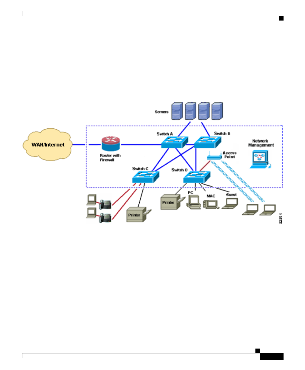
Figure 1-1 is an example network using Catalyst Express switches. Devices
outside the dotted line are network users and network resources, such as servers
and printers. Devices within the dotted line are switches, routers, and access
points that enable communication between network users and provide access to
network resources.
Figure 1-1 Catalyst Express Network Example
Overview
OL-8122-01
Any of the Catalyst Express switch models can be Switches A, B, C, and D in this
network. To take full advantage of the different switch models, use the model that
is designed for the type of connections that you require.
For example, use the Catalyst Express 500G-12TC for Switches A and B. This
model has the most Gigabit Ethernet ports, and it is best suited to providing
1000-Mbps connections between switches and to servers.
Use either the Catalyst Express 500-24TT or the Catalyst Express 500G-12TC for
Switches C and D. These switches are designed to provide high-speed (up to
100 Mbps and 1000 Mbps, respectively) connections to network users.
If you need to connect PoE devices to your network, use the Catalyst
Express 500-24LC and the Catalyst Express 500-24PC. These switches can
provide power to up to 4 or up to 24 PoE devices, respectively.
User Guide for the Catalyst Express 500 Switches
1-3
Page 4

Features and Benefits
Chapter 1 Introduction
PoE connections from the switch provide both power and network access to
PoE-capable devices, such as IP phones and access points. PoE devices can
receive up to 15.4 W of power from their connections to the switch. PoE also helps
reduce cabling costs. You can place PoE devices where power outlets are not
available or are not convenient.
Multiple connections between the switches ensure that users maintain network
access if any of the switches becomes overused or unavailable.
A network administrator can manage the network onsite or remotely through the
device manager GUI (embedded in the Catalyst Express switches), through Cisco
Network Assistant, or through a Simple Network Management Protocol
(SNMP)-based network management application. For more information about
managing the switches, see the “Device Manager GUI” section on page 1-8 and
the “Switch Management Options” section on page 1-11.
For more information about how to optimize the connections in a Catalyst Express
network, see the “Optimize Ports through Smartports Port Roles” section on
page 3-2.
Features and Benefits
• Hardware Features, page 1-5
• Software Features, page 1-7
• Device Manager GUI, page 1-8
User Guide for the Catalyst Express 500 Switches
1-4
OL-8122-01
Page 5
Chapter 1 Introduction
Catalyst Express 500
SERIES
2
1
1X
2X
P
O
W
E
R
O
V
E
R
E
T
H
E
R
N
E
T
11X
12X
4
3
6
5
8
7
10
9
12
11
14
13
13X
14X
23X
24X
16
15
18
17
20
19
22
21
24
23
25
25
26
26
SY
ST
EM
A
LE
R
T
P
oE
SETUP
Hardware Features
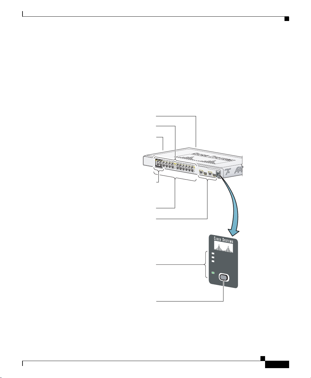
Figure 1-2 and the list that follows describe the switch hardware features and the
benefits that they provide. All switches can be installed on a table top, in a rack,
or mounted on a wall. For hardware installation information, see the “Install the
Switch” section on page 2-5.
Figure 1-2 Catalyst Express 500 Hardware Overview
(PoE) ports supply up to
Features and Benefits
AC power connector
Port LEDs
Security cable slot
side and rear panels
Power over Ethernet
15.4 W per port
OL-8122-01
Fast Ethernet ports
Dual-purpose uplink ports:
SFP module and
10/100/1000BASE-T
Autonegotiate and auto-MDIX
enabled on all ports
Switch LEDs:
SYSTEM - switch status
ALERT - events detected
SYSTEM
ALERT
PoE
SETUP
PoE - PoE status
SETUP - setup mode
SETUP button
User Guide for the Catalyst Express 500 Switches
1-5
Page 6

Chapter 1 Introduction
Features and Benefits
10/100-Mbps Fast Ethernet Ports
10/100/1000-Mbps Gigabit Ethernet Ports
• Autosensing (autonegotiation) of port speed and autonegotiating of duplex mode optimizes port
bandwidth.
• Automatic-medium-dependent interface crossover (auto-MDIX) capability automatically detects
the required cable connection type (straight-through or crossover) and configures the connection
appropriately.
PoE-Capable Ports (Available only on the Catalyst Express 500-24LC and Catalyst Express 500-24PC
switches.)
• Up to 15.4 W of power provided to connected Cisco prestandard and IEEE 802.3af-compliant
powered devices if the switch detects that there is no power on the circuit.
SFP Module Slots
• Fiber-optic SFP modules provide cable media and distance options for switch connectivity. A list
of supported Cisco SFP modules is in the “Supported Hardware” section on page 1-13.
LEDs
• System LEDs show switch status, problem detection, PoE usage, and setup status.
• Port LEDs show port status. From the device manager GUI, port LEDs also show duplex mode,
speed, and PoE status.
• RPS LED shows status of an installed Cisco redundant power supply (RPS). (Available only on the
Catalyst Express 500-24PC model.)
Setup Button
• Button starts the Express Setup program.
Cisco Redundant Power Supply (RPS)
• Cisco redundant power supply (RPS) enhances power reliability. A list of supported RPS models
is in the “Supported Hardware” section on page 1-13. (Available only on the Catalyst
Express 500-24PC model.)
Security Slots
• Slots to attach a security cable to the switch.
1-6
User Guide for the Catalyst Express 500 Switches
OL-8122-01
Page 7

Chapter 1 Introduction
Features and Benefits
Software Features
These are the switch software features and the benefits that they provide. You can
configure these features through the device manager GUI (see the “Device
Manager GUI” section on page 1-8). For details on these features, see the chapters
on Customization, Monitoring, and Troubleshooting.
Note For enhanced switch features that are available only through Network Assistant
and not through the device manager GUI, see the “Cisco Network Assistant”
section on page 1-12.
Express Setup
• Initial setup only requires IP information for first-time switch configuration.
• Quick IP information updates if you relocate the switch to a different network.
• Date and time settings automatically synchronized between the switch and the network
management station.
• Dynamic Host Configuration Protocol (DHCP) automatically assigns the switch an IP address, a
default gateway, and a subnet mask from a DHCP server.
Troubleshooting
• General switch diagnostic test detects problems on the switch. Link diagnostic test detects
cable-related issues on a specified port.
• General switch and link diagnostic reports describe problems detected on the switch and its ports
and list recommended actions to resolve each problem.
Monitoring
• Alert LED notifies that one or more problems were detected on the switch.
• Alert Log lists all problems detected on the switch, including a timestamp of the most recent
detection of each problem.
• Graphical front panel display, LEDs, gauges, graphs, and animated indicators show switch and port
status, utilization, and error percentages, and temperature and fan status.
• Port status and statistics tables display port operating status and the statistics for data being
received and sent on each port.
User Guide for the Catalyst Express 500 Switches
OL-8122-01
1-7
Page 8

Chapter 1 Introduction
Features and Benefits
Customization
• Smartports port roles optimize switch ports according to their attached devices. Security and
quality of service (QoS) benefits are built into the port roles.
• Secure Socket Layer (SSL) protocol authenticates and encrypts communications to the switch
device manager GUI. (Requires the cryptographic version of the switch software available from
the software download page on Cisco.com.)
• Username-and-password pair configuration for controlling switch access.
• VLANs for grouping network users according to functions, teams, or applications, and regardless
of the physical location of the network users. The switch supports up to 32 VLANs.
VLAN support includes these features:
–
Spanning Tree Protocol (STP) prevents network loops from developing and provides a
redundant path if the active path becomes unavailable.
–
Internet Group Management Protocol (IGMP) snooping reduces duplicate and excess traffic
on the network.
• EtherChannels for bundling multiple Fast Ethernet or Gigabit Ethernet ports into a single logical
link to create a higher bandwidth link between the switch and another switch.
• Simple Network Management Protocol (SNMP) versions 1, 2C, and 3 to allow a remote network
management station to access, monitor, and control the switch.
Device Manager GUI
The device manager is a graphical device management tool for configuring,
monitoring, and troubleshooting the switch (Figure 1-3).
It simplifies configuration tasks with features such as Express Setup and
Smartports for quickly setting up the switch and its ports. It uses graphical,
color-coded displays such as the switch front panel view, graphs, and animated
indicators to simplify monitoring tasks. It provides alert and diagnostic tools to
help you identify and solve networking problems.
Additional details about the device manager and procedures on using the device
manager windows are available from the device manager online help (Figure 1-4).
You can display the device manager from anywhere in your network through a
web browser such as Microsoft Internet Explorer or Netscape Navigator. For
information on how to display the device manager, see the “Display the Device
Manager” section on page 2-13.
User Guide for the Catalyst Express 500 Switches
1-8
OL-8122-01
Page 9

Chapter 1 Introduction
Features and Benefits
Figure 1-3 Device Manager Interface
OL-8122-01
User Guide for the Catalyst Express 500 Switches
1-9
Page 10

System Requirements
Chapter 1 Introduction
Figure 1-4 Device Manager Online Help
System Requirements
• Hardware Requirements, page 1-11
• Software Requirements, page 1-11
User Guide for the Catalyst Express 500 Switches
1-10
OL-8122-01
Page 11

Chapter 1 Introduction
Hardware Requirements
Table 1- 2 lists the minimum hardware requirements for running the device
manager.
Table 1-2 Hardware Requirements
Processor Speed DRAM Number of Colors Resolution Font Size
Intel Pentium II
1. We recommend Intel Pentium 4.
2. We recommend 256-MB DRAM.
Software Requirements
Table 1- 3 lists the supported operating systems and browsers for using the device
manager. The device manager verifies the browser version when starting a session
to ensure that the browser is supported.
You should disable any pop-up blockers or proxy settings in your browser
software and any wireless clients running on your PC.
Switch Management Options
1
64 MB
2
256 1024 x 768 Small
Table 1-3 Supported Operating Systems and Browsers
Operating System Microsoft Internet Explorer
Windows 2000 5.5 or 6.0 7.1
Windows XP 5.5 or 6.0 7.1
1. Service Pack 1 or higher is required for Internet Explorer 5.5.
Switch Management Options
In addition to the device manager GUI, you can also use these tools to manage the
switch:
• Cisco Network Assistant, page 1-12
• Simple Network Management Protocol, page 1-13
User Guide for the Catalyst Express 500 Switches
OL-8122-01
1
Netscape Navigator
1-11
Page 12

Switch Management Options
Cisco Network Assistant
The switches support the Cisco Network Assistant network management
application. Network Assistant offers an enhanced set of features for configuring
and monitoring one or more devices, including switches, device clusters, device
stacks, routers, and access points.
Catalyst Express 500 features that are available on Network Assistant but not
available from the device manager include:
• Levels (Low, Medium, or High) of network security and switch access for
devices attached to the switch
• Smartports Diagnostics port role to optimize the connection between a switch
port and a network troubleshooting device
• Device inventory to retrieve information such as the IP address, the MAC
address, and the port role information of devices connected to the switch
Some general Network Assistant features include:
• Centralized, common services—such as software upgrades, configuration
management, inventory reports, network events, alerts, and password
synchronization—for Cisco switches, routers, and access points in the
network
Chapter 1 Introduction
1-12
• Centralized network monitoring using two different views of all connected
devices in the network: a physical view (front panel images) and a logical
view (network topology image of different network devices, including IP
phones)
• Drag-and-drop software upgrade for multiple switches, including
backup-and-restore through a switch configuration file
• Security configuration for all the Cisco access points in the network
• Interactive tools (such as wizards) to simplify configuration of complex
features
For more information, see the Cisco Network Assistant Introduction at this URL:
http://www.cisco.com/go/networkassistant
User Guide for the Catalyst Express 500 Switches
OL-8122-01
Page 13

Chapter 1 Introduction
Simple Network Management Protocol
You can use Simple Network Management Protocol (SNMP) management
applications to manage the switch. You also can manage it from an
SNMP-compatible workstation.
Supported Hardware
The switches support the PWR675-AC-RPS RPS. (Available only on the Catalyst
Express 500-24PC model.)
The switches support these Cisco SFP modules:
• 100BASE-BX
• 100BASE-FX
• 100BASE-LX
• 1000BASE-LX
• 1000BASE-SX
Supported Hardware
When You Are Done
If you have not already installed the switch and configured its basic settings, see
Chapter 2, “Setup and Installation.”
If you already installed and configured the switch with its basic settings, see
Chapter 3, “Customization,” to learn about features that can optimize the switch
performance.
OL-8122-01
User Guide for the Catalyst Express 500 Switches
1-13
Page 14

When You Are Done
Chapter 1 Introduction
1-14
User Guide for the Catalyst Express 500 Switches
OL-8122-01
 Loading...