

Page 1

Contents
Cisco XR 12000 Series Router
Ethernet Line Card Installation
August 1, 2005
Document Part Number: OL-7861-01
This guide contains instructions for installing Ethernet line cards in supported Cisco XR 12000 Series
Routers. Also included are basic troubleshooting techniques to help in line card installation.
This installation guide includes the following sections:
• Important Information, page 2
• Product Overviews, page 4
• Preparing for Installation, page 8
• Removing and Installing a Line Card, page 10
• Removing and Installing EPAs, page 15
• Removing and Installing GBICs, page 22
• Removing and Installing SFP Modules, page 25
• Line Card Cable-Management Bracket, page 36
• Cabling and Specifications, page 41
• Verifying and Troubleshooting the Installation, page 57
• Line Card Memory, page 64
• Regulatory, Compliance, and Safety Information, page 78
• Obtaining Documentation, page 82
• Obtaining Technical Assistance, page Boilerplate 1
• Obtaining Additional Publications and Information, page Boilerplate
Corporate Headquarters:
Cisco Systems, Inc., 170 West Tasman Drive, San Jose, CA 95134-1706 USA
Copyright © 2005 Cisco Systems, Inc. All rights reserved.
Page 2
Important Information
Important Information
This section contains information about the following topics:
• Ethernet Line Card Product Numbers, page 2
• Router Hardware Installation, page 2
• Cisco IOS Software Release and Hardware Revision Requirements, page 3
• Memory Options, page 4
• Related Documentation, page 4
Ethernet Line Card Product Numbers
Table 1 lists the Cisco product numbers to which this publication applies. This guide replaces the
individual Ethernet line card installation documents for the Cisco 12000 Series Router.
Table 1 Ethernet Line Card Product Numbers
Ethernet Line Card Cisco Product Number
4-Port Gigabit Ethernet Internet Services
Engine (ISE) Line Card
10-Port 1-Gigabit Ethernet Line Card 10X1GE-SFP-LC=
1-Port 10-Gigabit Ethernet Line Card 1X10GE-LR-SC=
4GE-SFP-LC=
10X1GE-SFP-LC-B=
1X10GE-ER-SC=
Router Hardware Installation
Forhardware installation information for Cisco XR 12000 Series Routers, referto the installation guide
for your router. The guide includes information on the router switch fabric and how it affects operation
of the line card, as well as line card slot locations, slot width, and other requirements.
Also refer to the field-replacable unit (FRU) publications that describe how to install, maintain, and
replace router subsystems, such as cooling fans, power supplies, chassis backplanes, and so on.
Supported Platforms
Table 2 lists the supported router platforms for Ethernet line cards:
Table 2 Ethernet Line Card Supported Router Platforms
Ethernet Line Card Supported Platform
4-Port Gigabit Ethernet ISE All Cisco 12000 Series Routers
10-Port 1-Gigabit Ethernet All Cisco 12400 and 12800 Routers
1-Port 10-Gigabit Ethernet All Cisco 12400 and 12800 Routers
Cisco XR 12000 Series Router Ethernet Line Card Installation
2
OL-7861-01
Page 3
Important Information
Note The Cisco XR 12000 Series Routers must have a full set of switch fabric cards installed to support the
requirements of the Ethernet line cards. See the appropriate Cisco 12000 Series Router installation
guide for information about the switch fabric and other related requirements.
Note Because the 10-Port 1-Gigabit Ethernet, 1-Port 10-Gigabit Ethernet, and Modular Gigabit Ethernet line
cards require a card cage slot that is 1.8 inches (4.5 centimeters) wide, you can use these line cards in
only the Cisco 12416 Router, Cisco 12410 Router, Cisco 12406 Router, Cisco 12404 Router, Cisco
12816 Router, and Cisco 12810 Router.
Cisco IOS Software Release and Hardware Revision Requirements
The Ethernet line cards have certain Cisco IOS software requirements. Also, to ensure compatibility with
the software, your Ethernet line card should have a specific hardware revision number. The number is
printed on a label affixed to the component side of the card and is displayed by the show diag command.
Table 3 lists the hardware and software requirements for Ethernet line cards.
Table 3 Ethernet Line Card and Cisco IOS Release and Hardware Version Compatibility
Line Card
Ethernet Line Card
4-Port Gigabit
Ethernet ISE
10-Port 1-Gigabit
Ethernet
1-Port 10-Gigabit
Ethernet
1. Cisco IOS Release 12.0(22)S does not support the 1X10GE-LR-SC Ethernet line cards.
Part Number Minimum IOS Software Release
4GE-SFP-LC= Cisco IOS Release 12.0(25)S or later 73-8517-03, revision A0 or later
10X1GE-LC= 12.0(19)S or later release of 12.0S; or 12.0(19)ST or
later release of 12.0ST
10X1GE-LC-B= 12.0(21)S or later release of 12.0S; or 12.0(21)ST or
1X10GE-LR-SC=
(LR laser optical
transceiver)
1X10GE-ER-SC=
(ER laser optical
transceiver)
later release of 12.0ST
12.0(23)S, or later, release of 12.0S
12.0(23)S, or later release of 12.0S 73-7182-01 or later
1
The show diag slot_number, show version, and show hardware commands display the current
hardware configuration of the router, including the system software version that is currently loaded and
running, and the hardware revision number. For complete descriptions of show commands, refer to the
Cisco IOS Configuration Fundamentals Configuration Guide and the Cisco IOS Configuration
Fundamentals Command Reference for the installed Cisco IOS release.
If the command displays indicate that the Cisco IOS software is a version earlier than you need, check
the contents of flash memory to determine if the required images are available on your system. The dir
devicename command displays a list of all files stored in flash memory. If you do not have the correct
software version, contact Cisco customer service.
For software configuration information, refer to the Cisco IOS software configuration and command
reference publications for the installed Cisco IOS release. Also refer to the Cisco IOS software release
notes for additional information.
Required
Hardware Version
73-5479-06 or later
73-7673-02 or later
73-7182-01 or later
OL-7861-01
Cisco XR 12000 Series Router Ethernet Line Card Installation
3
Page 4

Product Overviews
Memory Options
Ethernet line card memory options vary by line card. See “Line Card Memory” section on page 64 for
more information.
Related Documentation
This publication describes the basic installation of a Ethernet line card. For complete configuration
information, refer to the following publications:
• Cisco IOS XR Interface and Hardware Component Configuration Guide, Release 3.2
• Cisco IOS XR Interface and Hardware Component Command Reference, Release 3.2
• Cisco IOS XR Release 3.2 Release Notes for Cisco XR 12000 Series Routers
• Regulatory Compliance and Safety Information for Cisco XR 12000 Series Routers
See the “Obtaining Documentation” section on page Boilerplate 1for information on how to obtain these
publications.
Product Overviews
The following sections provide information about the Ethernet line card products:
• 4-Port Gigabit Ethernet ISE Line Card, page 5
• 10-Port 1-Gigabit Ethernet Line Card, page 6
• 1-Port 10-Gigabit Ethernet Line Card, page 8
Ethernet Line Card Comparison
Table 4 provides comparative information about Ethernet line cards. The first Ethernet line card has a
Fast Ethernet interface and the others have a Gigabit Ethernet interface.
Table 4 Ethernet Line Card Hardware Comparison
Line Card
Ethernet Line Card
4-Port Gigabit
Ethernet ISE
10-Port 1-Gigabit
Ethernet
Part Number Ports
4GE-SFP-LC= 4 X Single-mode or multimode fiber
10X1GE-SFP-LC= 10 X Single-mode or multimode fiber
10X1GE-SFP-LC-B= 10 X Single-mode or multimode fiber
GBIC
Pluggable
SFP
Pluggable
Insertable EPA
Daughter Card Cable and Connector
with LC connectors (depends on
SFP)
with LC connectors (depends on
SFP)
with LC connectors (depends on
SFP)
Cisco XR 12000 Series Router Ethernet Line Card Installation
4
OL-7861-01
Page 5
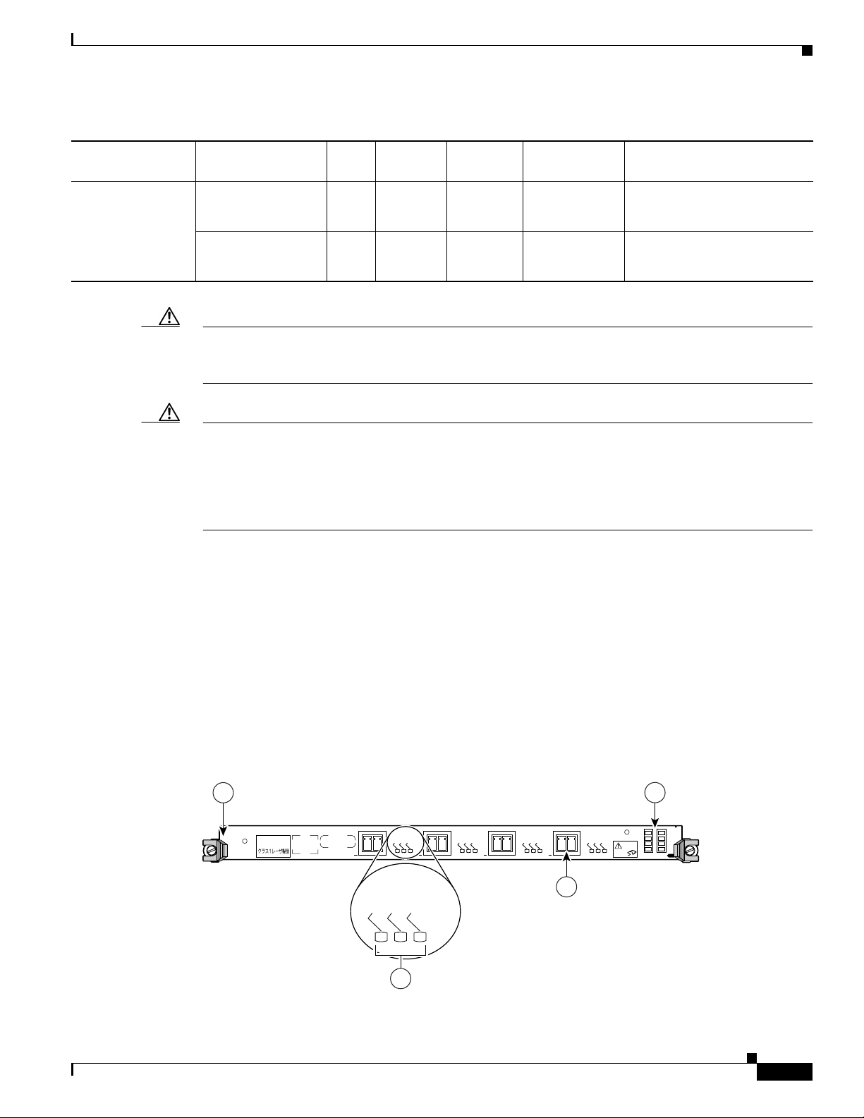
Table 4 Ethernet Line Card Hardware Comparison (continued)
Product Overviews
Ethernet Line Card
1-Port 10-Gigabit
Ethernet
Caution To preventsystem problems, do not use Gigabit Interface Converters(GBICs) from third-party vendors.
Caution Only use small form-factor pluggable modules (SFPs) supplied by Cisco in Cisco XR 12000 Series
Line Card
Part Number Ports
1X10GE-LR-SC=
(LR laser optical
GBIC
Pluggable
SFP
Pluggable
Insertable EPA
Daughter Card Cable and Connector
1 Single-mode fiber with SC
connectors
transceiver)
1X10GE-ER-SC=
(ER laser optical
1 Single-mode fiber with SC
connectors
transceiver)
Use only the GBIC that shipped with your Ethernet line card. The GBIC might contain an internal
EPROM that identifies it to the Cisco IOS software.
Routers. Each SFP module contains an internal serial number that is security programmed by the SFP
module manufacturer with information that provides a way for Cisco (through the Cisco IOS software)
to identify and validate the SFP module as a module type that is qualified by Cisco to operate with
Gigabit Ethernet line cards. Unapproved SFP modules (those not purchased directly from Cisco) do not
work.
4-Port Gigabit Ethernet ISE Line Card
The 4-Port Gigabit Ethernet ISE line card provides Cisco XR 12000 Series Routers with four optical
Gigabit Ethernet interfaces on a single line card, using field replaceable SFP modules. The line card
provides high-speed connections to other network devices, such as another Cisco XR 12000 Series
Router, other routers, or layer-2 and layer-3 switches that support Gigabit Ethernetinterfaces.The 4-Port
Gigabit Ethernet line card throughput is limited to 4 million packets per second (4 Mpps) at 64 bytes, so
all four ports cannot run at line rate.
Figure 1 shows the front view of the 4-Port Gigabit Ethernet ISE line card.
Figure 1 4-Port Gigabit Ethernet ISE Line Card
1
CLASS 1 LASER PRODUCT
LASERPRODUKT DER KLASSE 1
PRODUIT LASER DE CLASSE 1
PRODUCTO LASER DE CLASE 1
0
ACTIVE
ACTIVE
LINK
LINK
2
RX FRAME
1
RX FRAME
3
LINK
RX FRAME
ACTIVE
2
LINK
RX FRAME
ACTIVE
3
LINK
RX FRAME
ACTIVE
CLEAN
CONNECTOR
WITH ALCOHOL
WIPES BEFORE
CONNECTING
4GE-SFP-LC
4
84987
OL-7861-01
Cisco XR 12000 Series Router Ethernet Line Card Installation
5
Page 6
Product Overviews
1 Ejector lever (one at each end) 3 Alphanumeric LEDs
2 Status LEDs (one set per port) 4 Port (provided by SFP module)
Table 5 summarizes the optics and connectors used by the 4-Port Gigabit Ethernet ISE line card.
Table 5 4-Port Gigabit Ethernet ISE Line Card Optics and Connector Types
Part Number Optics/Transmission Maximum Distance Connector Type
4GE-SFP-LC See Table 14 on page 48. See Table 14 on page 48.LC
For more information, refer to the “Gigabit Ethernet SFP Modules” section on page 47 and the “Cabling
and Specifications” section on page 41.
The 4-Port Gigabit Ethernet ISE line card ships with 256 MB of route memory and 512 MB of packet
memory. Route memory is field serviceable. For more information on memory, see the “Line Card
Memory” section on page 64.
10-Port 1-Gigabit Ethernet Line Card
The 10-Port 1-Gigabit Ethernet line card, which is designed for high-density and server-aggregation
applications, provides the Cisco 12400 and 12800 Routers with 10 optical 802.3 Gigabit Ethernet
interfaces on a single line card. These interfaces provide high-speed connections to other network
devices, such as another Cisco 12000 Series Router, other routers, or layer-2 or layer-3 switches that
support Gigabit Ethernet interfaces. Figure 2 shows a front view of the line card.
The 10 ports on the front panel of the line card are numbered 0 through 9, from the top of the card to the
bottom. Each port consists of a receptacle for a field-replaceable SFP laser optical transceiver module,
which is inserted into the receptacle to provide the Gigabit Ethernet optical interface.
Next to each port on theline card are three green LEDs, aligned vertically and labeled from top to bottom
as follows: LINK, ACTIVE, and RX FRAME.
Note The 10X1GE-SFP-LC-B version of this card is not shown. The 10X1GE-SFP-LC-B model
of the 10-Port 1-Gigabit Ethernet line card is enhanced with minor hardware features that
are not available with the original design.
Cisco XR 12000 Series Router Ethernet Line Card Installation
6
OL-7861-01
Page 7
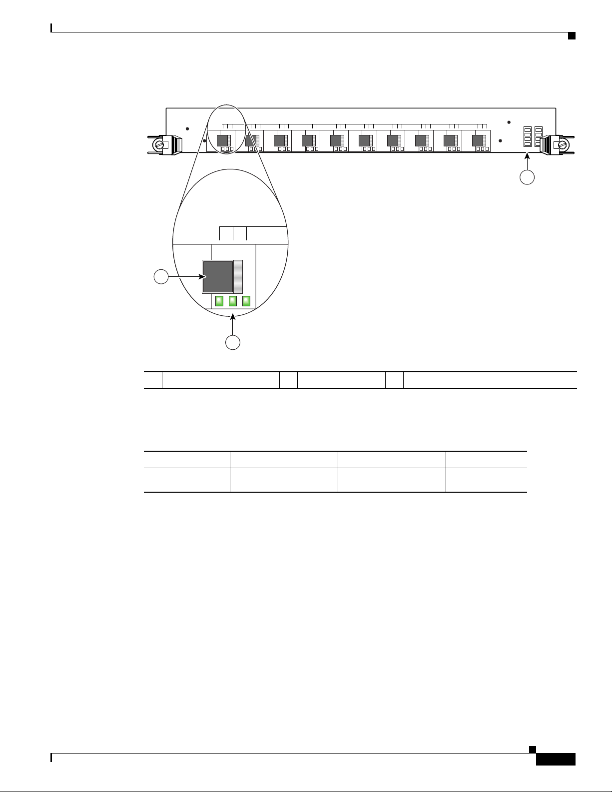
Figure 2 10-Port 1-Gigabit Ethernet Line Card
LINK
ACTIVE
RX FRAME
LINK
ACTIVE
RX FRAME
0
1
Product Overviews
76543210
98
10X1GE-SFP-LC
98892
3
2
1 SFP module receptacle 2 Port status LEDs 3 Alphanumeric LEDs
Table 6 summarizes the optics and connectors used by the 10-Port 1-Gigabit Ethernet line card.
Table 6 10-Port 1-Gigabit Ethernet Line Card Optics and Connector Types
Part Number Optics/Transmission Maximum Distance Connector Type
10X1GE-SFP-LC,
10X1GE-SFP-LC-B
See Table 14 on page 48. See Table 14 on page 48.LC
For more information, refer to the “Gigabit Ethernet SFP Modules” section on page 47 and “Cabling and
Specifications” section on page 41.
The 10-Port 1-Gigabit Ethernet line card ships with the following memory configurations installed:
• 256 MB of route processor memory (Product Number MEM-LC4-256)
• 512 MB of packet memory (Product Number MEM-LC4-PKT-512)—256 MB in both the receive
and transmit directions
Line card memory on Engine 4 line cards (packet and route memory) is not field replaceable. For more
information on memory, see the “Line Card Memory” section on page 64.
OL-7861-01
Cisco XR 12000 Series Router Ethernet Line Card Installation
7
Page 8
Preparing for Installation
1-Port 10-Gigabit Ethernet Line Card
The 1-Port 10-Gigabit Ethernet line card provides the supported Cisco XR 12000 Series Routers with
one optical 802.3ae 10-Gigabit Ethernet interface. This interface provides a high-speed connection to
other network devices, such as Cisco XR 12000 Series Routers, or to other routers or layer-2 or layer-3
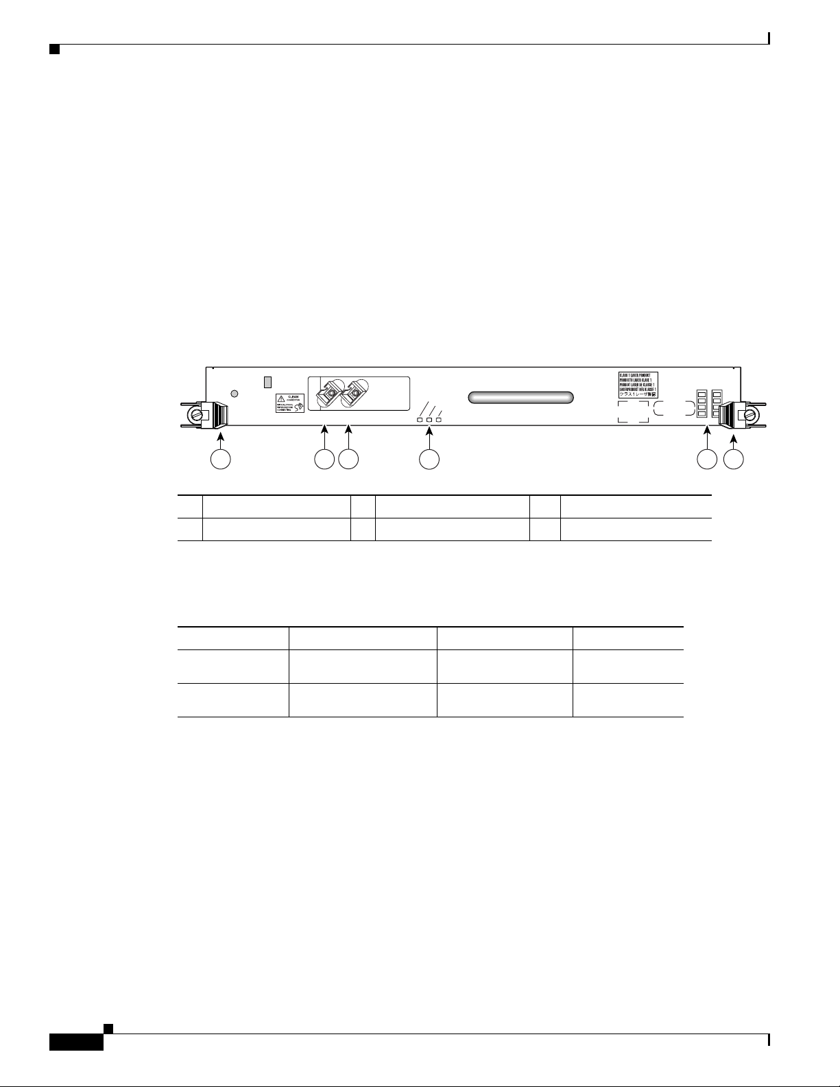
switches that support 10-Gigabit Ethernet interfaces. Figure 3 shows the front view of the line card.
The port on the front panel of the line card is port number 0. This port uses a hardwired laser optical
transceiver to provide a 10-Gigabit Ethernet optical interface. The transceiver consists of two optical
interfaces—laser transmit (TX) and laser receive (RX)—that use SC connectors.
Next to the port on the line card are three green LEDs, aligned vertically and labeled from top to bottom
as follows: LINK, ACTIVE, and RX FRAME.
Figure 3 1-Port 10-Gigabit Ethernet Line Card
LINK
ACTIVE
4
RX FRAME
1X10GE-LR-SC
51 2
6
TX
RX
3
1 Ejector lever 3 RX port 5 Alphanumeric LEDs
2 TX port 4 Status LEDs 6 Ejector lever
Table 7 summarizes the optics and connectors used by the 1-Port 10-Gigabit Ethernet line card.
Table 7 1-Port 10-Gigabit Ethernet Line Card Optics and Connector Types
Part Number Optics/Transmission Maximum Distance Connector Type
1X10GE-LR-SC 1550 nm (send),
1300 nm-1570 nm (receive)
1X10GE-ER-SC 1550 nm (send),
1300 nm-1570 nm (receive)
20 km SC
75 km SC
For more information, refer to the “10-Gigabit Ethernet” section on page 49 and the “Cabling and
Specifications” section on page 41.
The 1-Port 10-Gigabit Ethernet line card ships with 256 MB of route processor memory and 512 MB of
packet memory. The memory in the 1-Port 10-Gigabit Ethernet line card is not field replaceable. For
more information on memory, see the “Line Card Memory” section on page 64.
98893
Preparing for Installation
The following sections provide information about preparing to install line cards:
• Safety Guidelines, page 9
• Preventing Electrostatic Discharge, page 9
Cisco XR 12000 Series Router Ethernet Line Card Installation
8
OL-7861-01
Page 9

• Required Tools and Equipment, page 10
Safety Guidelines
Before you perform any procedure in this publication, review the safety guidelines in this section to
avoid injuring yourself or damaging the equipment.
The following guidelines are for your safety and to protect equipment. The guidelines do not include all
hazards. Be alert.
Note Review the safety warnings listed in the Regulatory Compliance and Safety Information for
Cisco 12000 Series Internet Router publication (Document Number 78-4347-xx) that accompanied your
router before installing, configuring, or maintaining a line card.
• Keep the work area clear and dust free during and after installation. Do not allow dirt or debris to
• Do not wear loose clothing, jewelry, or other items that could get caught in the router while working
• Cisco equipment operates safely when it is used in accordance with its specifications and product
Preparing for Installation
enter into any laser-based components.
with line cards.
usage instructions.
Before working with laser optics, read the “Laser Safety” section on page 81.
Preventing Electrostatic Discharge
Electrostatic discharge (ESD) damage, which can occur when electronic cards or components are
improperly handled, results in complete or intermittent failures. Electromagnetic interference (EMI)
shielding is an integral component of the line card. Cisco recommends using an ESD-preventive strap
whenever you are handling network equipment or one of its components.
The following are guidelines for preventing ESD damage:
• Always use an ESD-preventive wrist or ankle strap and ensure that it makes good skin contact.
Connect the equipment end of the connection cord to an ESD connection socket on the router or to
bare metal on the chassis.
• Handle Ethernet line cards by the captive installation screws, the provided handle, ejector levers, or
the line card metal carrier only; avoid touching the board or connector pins.
• Place removed Ethernet line cards board-side-up on an antistatic surface or in a static shielding bag.
If you plan to return the component to the factory, immediately place it in a static shielding bag.
• Avoid contact between the Ethernet line cards and clothing. The wrist strap only protects the board
from ESD voltages on the body; ESD voltages on clothing can still cause damage.
Warning
For safety, periodically check the resistance value of the ESD strap. The measurement should be
between 1 and 10 megohms.
OL-7861-01
Cisco XR 12000 Series Router Ethernet Line Card Installation
9
Page 10

Removing and Installing a Line Card
Required Tools and Equipment
You need the following tools and parts to remove and install Ethernet line cards:
• Flat-blade or Phillips screwdriver
• ESD-preventive wrist or ankle strap and instructions
• Interface cables to connect the Ethernet line card with another router or switch
• Any EPAs, GBICs, SFP modules, or memory you need to install (and are not already installed)
Note If you need additional equipment, see Cisco.com or your service representative for ordering information.
Refer to the individual line card descriptions in the “Product Overviews” section on page 4 for more
information. Table 4 on page 4 summarized the hardware requirements for each Ethernet line card.
Removing and Installing a Line Card
The following sections provide procedures for removing or installing a line card:
• Guidelines for Line Card Removal and Installation, page 10
• Removing a Line Card, page 11
• Installing a Line Card, page 13
Note See the “Guidelines for Line Card Removal and Installation” section on page 10 before removing a line
card while power to the router is on.
Note The procedures in the following sections use illustrations of a Cisco 12012 Internet Router to support
the descriptions of removing and installing line cards. Although the card cages of the Cisco 12000 Series
Routers differ in the number of card slots, the designated use of slots and the process of removing and
installing a line card are basically the same. Therefore, separate procedures and illustrations for other
Cisco routers are not included in this publication.
Guidelines for Line Card Removal and Installation
Guidelines for line card removal and installation include the following:
• Online insertion and removal (OIR) is supported, enabling youto removeand install line cards while
the router is operating. OIR is seamless to users on the network, maintains all routing information,
and ensures session preservation.
Note With OIR, notifying the software or resetting the power is not required. However, you have the
option of using the shutdown command before removing a line card.
10
Cisco XR 12000 Series Router Ethernet Line Card Installation
OL-7861-01
Page 11

Removing and Installing a Line Card
• After you reinstall a line card, the router automatically downloads the necessary software from the
route processor (RP). Next, the router brings online only those interfaces that match the current
configuration and were previously configured as administratively up. You must configure all others
with the configure command.
Caution The router may indicate a hardware failure if you do not follow proper procedures. Remove
or insert only one line card at a time. Allow at least 15 seconds for the router to complete the
preceding tasks before removing or inserting another line card.
After removing and inserting a line card into the same slot, allow at least 60 seconds before
removing or inserting another line card.
• Line cards have two ejector levers to release the card from its backplane connector. Use the levers
when you are removing the line card and to seat the line card firmly in its backplane connector when
you are installing the line card. The ejector levers align and seat the card connectors in the
backplane.
Caution When you remove a line card, always use the ejector levers to ensure that the connector pins
disconnect from the backplane in the sequence expected by the router. Any card that is only
partially connected to the backplane can halt the router.
When you install a line card, always use the ejector levers to ensure that the card is correctly
aligned with the backplane connector; the connector pins should make contact with the
backplane in the correct order, indicating that the card is fully seated in the backplane. If a
card is only partially seated in the backplane, the router will hang and subsequently crash.
Removing a Line Card
If you are replacing a failed line card, remove the existing line card first, then install the new line card
in the same slot. To remove a line card, use Figure 4 as a reference and follow these steps:
Step 1 Attach an ESD-preventive wrist or ankle strap and follow its instructions for use.
Step 2 Disconnect and remove all interface cables from the ports; note the current connections of the cables to
the ports on the line card.
Step 3 Detach the line card cable-management bracket from the line card.
Step 4 Use a screwdriver to loosen the captive screw at each end of the line card faceplate. (See Figure 4a.)
OL-7861-01
Cisco XR 12000 Series Router Ethernet Line Card Installation
11
Page 12
Removing and Installing a Line Card
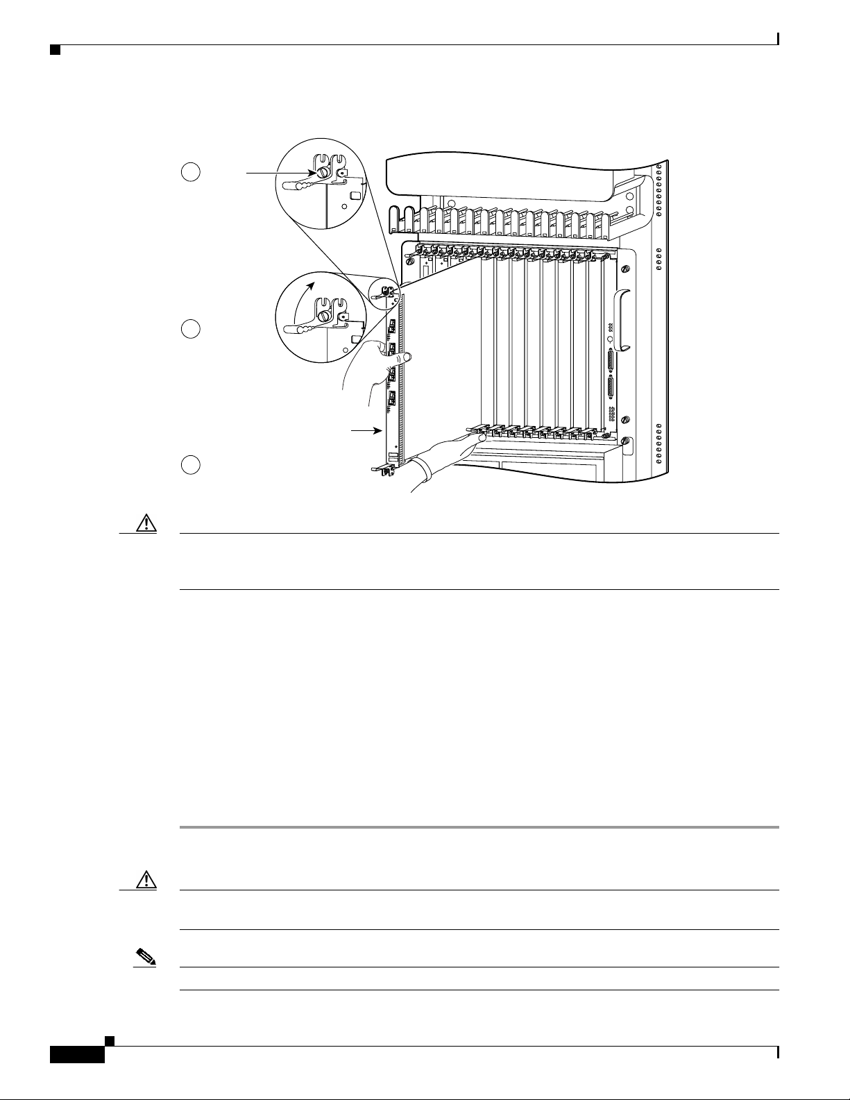
Figure 4 Line Card Removal and Installation
a
Loosen
captive
screws
b
Pivot ejector
levers away
from card to
unseat card
c
Grasp card carrier to
slide card out of slot
Line card
0
ACTIVE
CARRIER
RX PKT
1
ACTIVE
CARRIER
RX PKT
2
ACTIVE
CARRIER
RX PKT
3
ACTIVE
CARRIER
RX PKT
Q OC-3/STM-POS
EJECT
SLOT-0
SLOT-1
RESET
AUX
CONSOLE
LINK
COLL
TX
RX
MII
RJ-45
GIGABIT ROUTE PROCESSOR
0
1
2
3
Q OC-3/STM-POS
ACTIVE
CARRIER
RX PKT
0
0
ACTIVE
ACTIVE
ACTIVE
CARRIER
CARRIER
CARRIER
RX PKT
RX CELL
RX CELL
ACTIVE
CARRIER
RX PKT
ACTIVE
CARRIER
RX PKT
OC-12/STM-4 ATM
OC-12/STM-4 POS
CRITICAL
MAJOR
MINOR
ACO/LT
ALARM 1 ALARM 2
ENABLED
FAIL
0
CSC
1
0
1
SFC
ALARM
2
H10705
Caution When you remove a line card, always use the ejector levers to ensure that the line card connector pins
disconnect from the backplane in the logical sequence expected by the router. Any line card that is only
partially connected to the backplane can halt the router.
Step 5 Simultaneously pivot the ejector levers away from each other to release the line card from the backplane
connector. (See Figure 4b.)
Step 6 Grasp the ejector levers and pull the line card halfway out of the slot.
Step 7 Grasp the line card and gently pull it straight out of the slot, keeping your other hand under the line card
to guide it. (See Figure 4c.) Avoid touching the line card printed circuit board, components, or any
connector pins.
Step 8 Place the removed line card on an antistatic mat, or immediately place it in an antistatic bag if you plan
to return it to the factory.
Step 9 If the line card slot is to remain empty, install a line card blank (Product Number MAS-GSR-BLANK)
to keep dust out of the chassis and to maintain proper airflow through the line card compartment. Secure
the line card blank to the chassis by tightening its captive screws.
Caution Be careful not to damage or disturb the EMI spring fingers located on the front edge of the card face
plate.
12
Note Always insert a dust plug in an optical port opening for each port that is not in use.
Cisco XR 12000 Series Router Ethernet Line Card Installation
OL-7861-01
Page 13
For information on disconnecting interface cables, see the “Removing and Installing Fiber-Optic
Interface Cables” section on page 51.
For information on removing the cable-management bracket, see the “Removing a Line Card
Cable-Management Bracket” section on page 38.
Installing a Line Card
A line card slides into almost any available line card slot and connects directly to the backplane. If you
install a new line card, you must first remove the line card blank from the available slot.
Note Refer to the installation and configuration guide for your router for information on line card slot types,
slot width, and slot location.
Caution The router may indicate a hardware failure if you do not follow proper procedures. Remove or insert
only one line card at a time. Allow at least 15 seconds for the router to complete the preceding tasks
before removing or inserting another line card.
Removing and Installing a Line Card
To install a line card, follow these steps:
Step 1 Attach an ESD-preventive wrist or ankle strap and follow its instructions for use.
Step 2 Choose an available line card slot for the line card, and verify that the line card interface cable is long
enough for you to connect the line card with any external equipment.
Caution To prevent ESD damage, handle line cards by the captive installation screws, the provided handle,
ejector levers, or the card carrier edges only. Do not touch any of the electrical components or circuitry.
Step 3 Grasp the faceplate (or handle) of the line card with one hand and place your other hand under the card
carrier to support the weight of the card; position the card for insertion into the card cage slot. Avoid
touching the line card printed circuit board, components, or any connector pins.
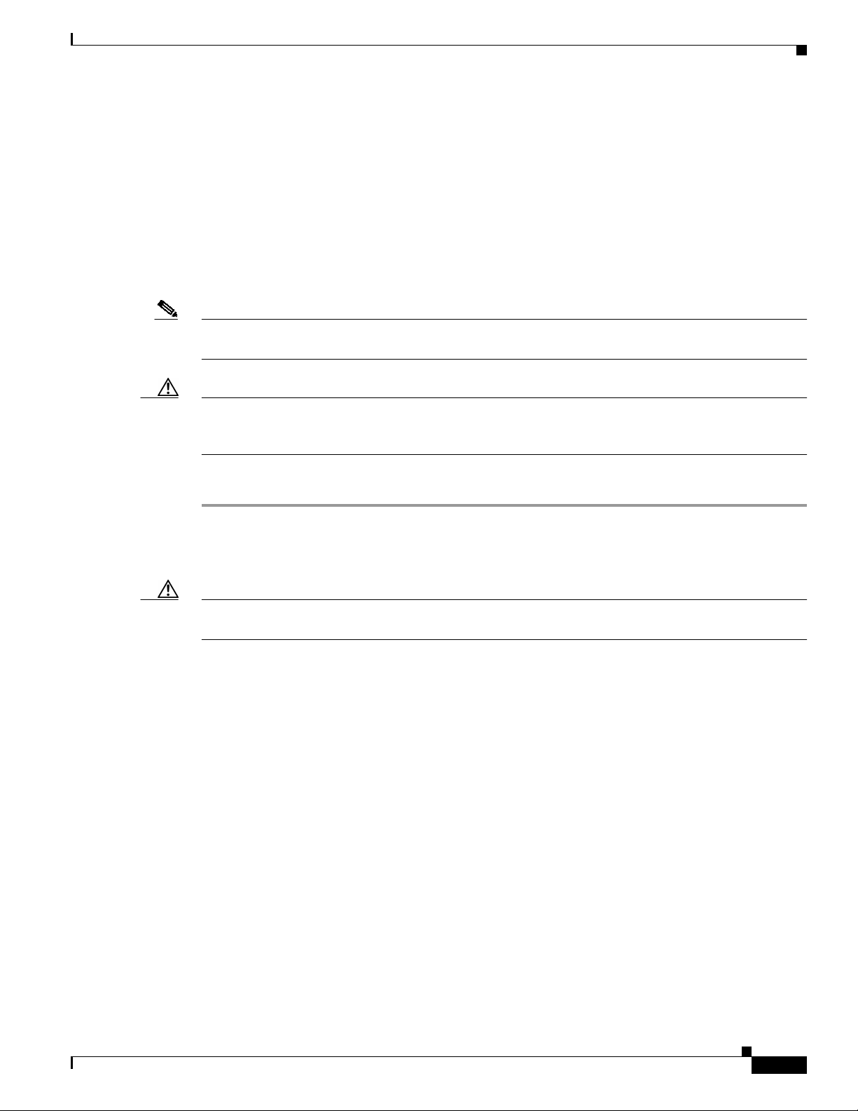
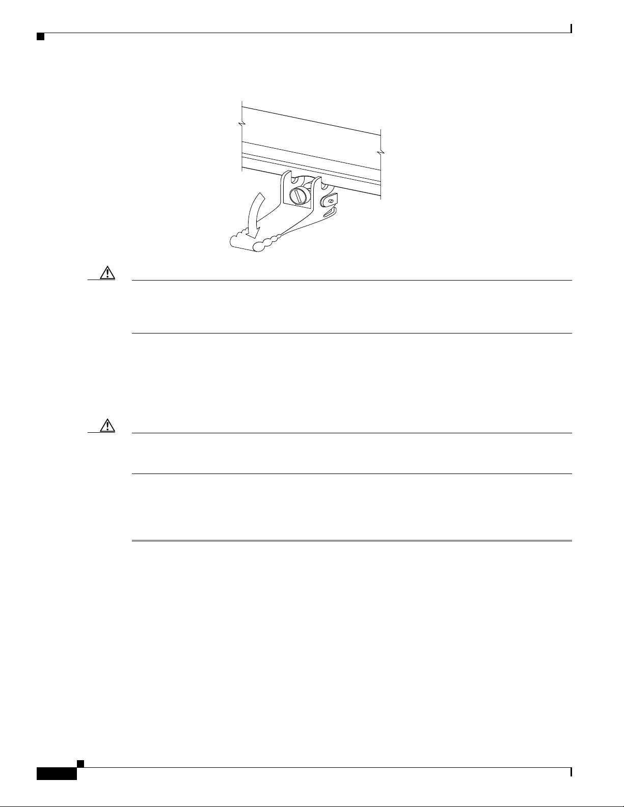
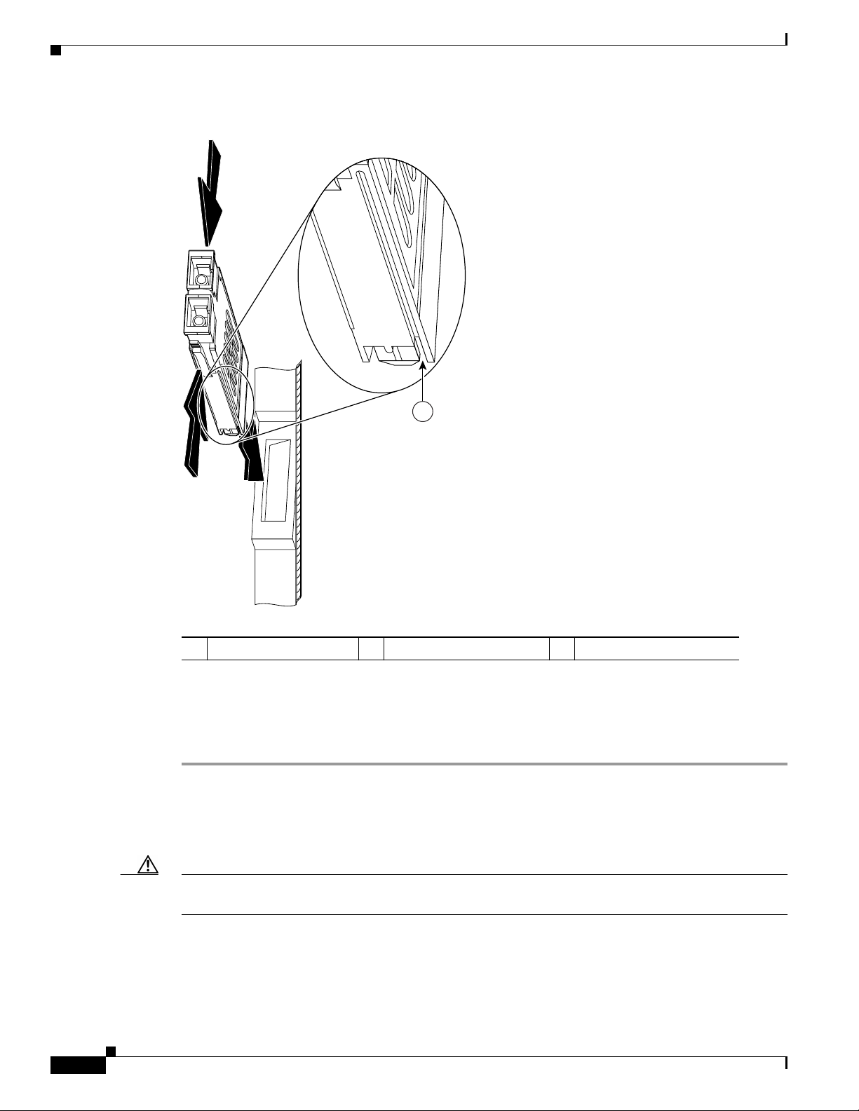
Step 4 Carefully slide the line card into the slot until the ejector levers make contact with the edges of the card
cage, then stop when the ejector lever hooks catch the lip of the card cage. If they do not catch, try
reinserting the line card until the ejector lever hooks are fully latched. (See Figure 5.)
OL-7861-01
Cisco XR 12000 Series Router Ethernet Line Card Installation
13
Page 14
Removing and Installing a Line Card
Figure 5 Ejector Levers
When inserting a card, make
sure the ejector lever hooks
catch the lip of the card cage.
Caution When you install a line card, always use the ejector levers to ensure that the card is correctly aligned
with the backplane connector, the card connector pins make contact with the backplane in the correct
order, and the card is fully seated in the backplane. A card that is only partially seated in the backplane
can cause the router to hang and subsequently crash.
H7681
Step 5 Simultaneously pivot both ejector levers toward each other until they are perpendicular to the line card
faceplate. This action firmly seats the card in the backplane.
Step 6 Use a 3/16-inch flat-blade screwdriver to tighten the captive screw on each end of the line card faceplate
to ensure proper EMI shielding and to prevent the line card from becoming partially dislodged from the
backplane.
Caution To ensure adequate space for additional line cards, alwaystighten the captive installation screwson each
newlyinstalledline card beforeyou insert any additional line cards. These screws also prevent accidental
removal and provide proper grounding and EMI shielding for the router.
Step 7 Install the cable-management bracket.
Step 8 Install GBIC or SFP modules, and EPA daughter cards, in the line cards that use them.
Step 9 Install the interface cables.
For information on installing cable-management brackets, see the “Installing a Line Card
Cable-Management Bracket” section on page 40.
For information on installing EPAs, see the “Removing and Installing EPAs” section on page 15.
For information on installing GBICs, see the “Removing and Installing GBICs” section on page 22.
For information on installing SFP modules, see the “Removing and Installing SFP Modules” section on
page 25.
For information on installing interface cables, see the “Removing and Installing Fiber-Optic Interface
Cables” section on page 51.
For information on verifying and troubleshooting the hardware installation, see the “Verifying and
Troubleshooting the Installation” section on page 57.
14
Cisco XR 12000 Series Router Ethernet Line Card Installation
OL-7861-01
Page 15
Removing and Installing EPAs
The Modular Gigabit Ethernet line card ships with 0, 1, 2, or 3 EPAs installed. If you need to add or
change an EPA, follow the procedures in these sections:
• Removing an EPA from the Modular Gigabit Ethernet Line Card, page 15
• Inserting an EPA into a Modular Gigabit Ethernet Line Card, page 17
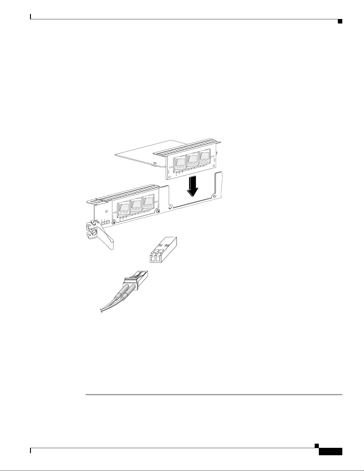
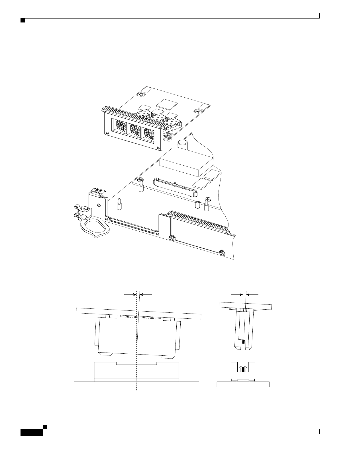
Figure 6 shows an exploded mechanical view of a Gigabit Ethernet EPA with three line card SFP
receptacles, an SFP module, and a duplex LC-type cable.
Figure 6 Removing and Replacing EPAs
Removing and Installing EPAs
2
1
0
EPA-3GE/SX/LH-LC
RX PKT
LINK
ACTIVE
2
1
0
EPA-3GE/SX/LH-LC
RX PKT
LINK
PA-2
ACTIVE
75547
CSA ID
PA-1
PA-0
Removing an EPA from the Modular Gigabit Ethernet Line Card
You can remove an EPA from the Modular Gigabit Ethernet line card with or without the SFP modules
installed.
To remove an EPA from your Modular Gigabit Ethernet line card, use Figure 7 on page 16 as a reference
and follow these steps:
OL-7861-01
Step 1 Attach an ESD-preventive wrist or ankle strap and follow its directions for use.
Step 2 Disconnect the LC-type fiber-optic cable connector from the SFP module.
Note which cable connector plug is TX and which is RX for reattachment.
Cisco XR 12000 Series Router Ethernet Line Card Installation
15
Page 16
Removing and Installing EPAs
Step 3 Insert a dust plug into the optical ports of the SFP module to keep the optical interfaces clean.
Step 4 Remove the Modular Gigabit Ethernet line card from the chassis, as described in the “Removing a Line
Card” section on page 11, and place the line card on a clean, flat surface.
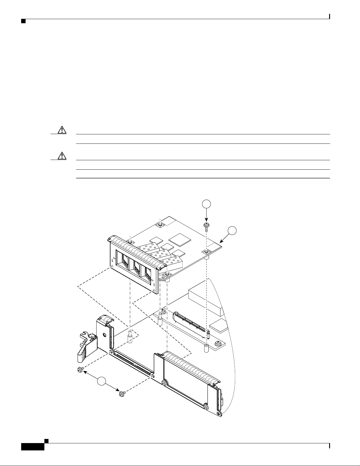
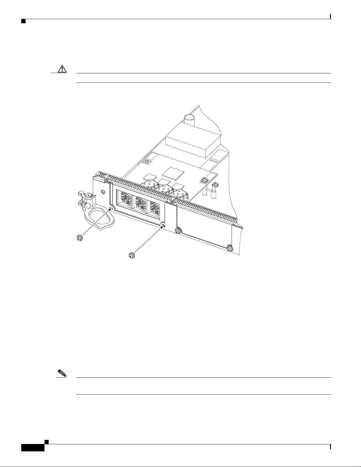
Step 5 Use a Phillips screwdriver to loosen and unscrew the two screws that connect the EPA to the line card,
located on the faceplate of the line card, as shown in Figure 7A.
Step 6 Use a Phillips screwdriver to loosen and unscrew the one screw that connects the EPA to the inside of
the line card, as shown in Figure 7B.
Step 7 Gently lift up on one corner of the EPA to disconnect the EPA from the line card, as shown in
Figure 7C.
Caution To prevent ESD damage, handle EPAs by the card carrier edges only.
Caution Avoid touching the EPA printed circuit board, components, or any connector pins.
Figure 7 Removing an EPA
INSTALL
PUSH
CORNERS
TO
B
C
LIFT
HERE
TO
REMOVE
16
A
75548
Cisco XR 12000 Series Router Ethernet Line Card Installation
OL-7861-01
Page 17
If the EPA bay is to remain empty, install an EPAblank (Product Number MAS-EPA-BLANK=) to keep
dust out of the line card and to maintain proper airflow and EMI through the line card and chassis.
Inserting an EPA into a Modular Gigabit Ethernet Line Card
To insert an EPA into the Modular Gigabit Ethernet line card, follow these steps:
Removing and Installing EPAs
Warning
Youmust use an ESD-preventive wrist or ankle strap to do this procedure. Attach an ESD-preventive
wrist or ankle strap and follow its directions for use, before you do this procedure.
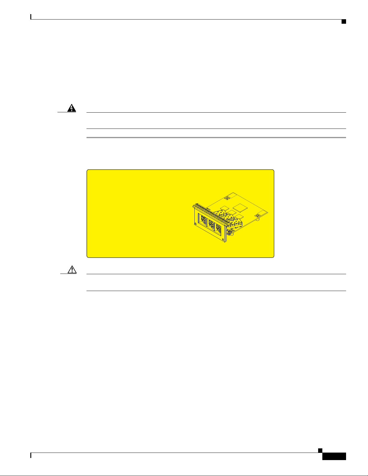
Step 1 First, read the yellow caution label on the EPA. Figure 8 shows a sample of this caution label.
Figure 8 Locations of Labels and Reference Points on the EPA
ATTENTION:
USE CARE DURING INSTALLATION OF EPA CARD,
MIS-ALIGNMENT CAN CAUSE DAMAGE TO THE
CONNECTOR AT THE UNDERSIDE REAR OF THE PCB.
DO NOT APPLY EXCESSIVE FORCE TO THE FRONT
PANEL OR TOP SURFACE DURING INSTALLATION OR
DAMAGE CAN OCCUR TO THE PCB CONNECTOR.
129768
Caution The connectors must be engagedwithout any angular misalignment. Engaging theconnectors at an angle
will cause damage to the connectors.
OL-7861-01
Cisco XR 12000 Series Router Ethernet Line Card Installation
17
Page 18
Removing and Installing EPAs
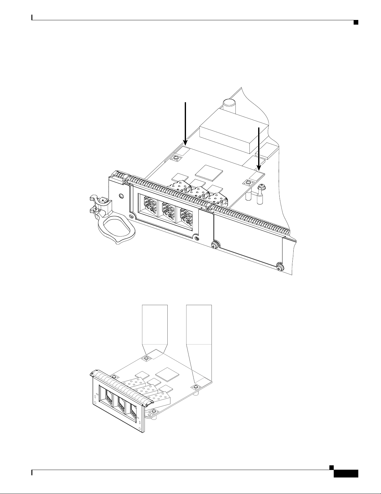
Step 2 Ensure that the connector guide pins are aligned, and mate the connector of the EPA to the connector on
the line card, as shown in Figure 9 and Figure 10. Figure 10 shows two side views of the EPA and line
card.
Figure 9 Mating the Connector of the EPA to the Line Card
PUSH
CORNERS
TO
INSTALL
PUSH
CORNERS
TO
INSTALL
129854
Figure 10 Side Views - Mating the Connector of the EPA to the Line Card
20˚ Max 4˚ Max
129857
18
Cisco XR 12000 Series Router Ethernet Line Card Installation
OL-7861-01
Page 19
Removing and Installing EPAs
Step 3 Ensure that the connector guide pins are aligned. Once the connector is engaged, apply gentle pressure
with your thumbs to the two rear outer corners of the EPA, as shown in Figure 11 and Figure 12.
Figure 11 Press on the Rear Outer Corners of the EPA
PUSH
CORNERS
TO
INSTALL
PUSH
CORNERS
TO
INSTALL
Figure 12 Rear Outer Corners of the EPA (Close-up)
PUSH
BOTH
CORNERS
TO
INSTALL
PUSH
BOTH
CORNERS
TO
INSTALL
PUSH
BOTH
CORNERS
TO
INSTALL
PUSH
BOTH
CORNERS
TO
INSTALL
129765
129855
OL-7861-01
Cisco XR 12000 Series Router Ethernet Line Card Installation
19
Page 20
Removing and Installing EPAs
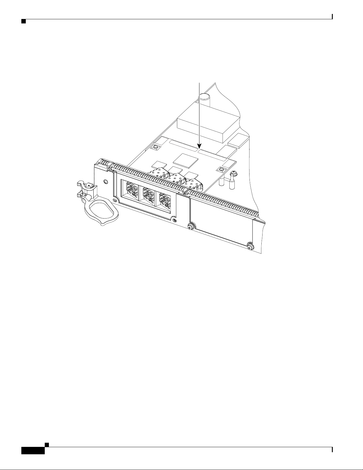
Step 4 Press gently on the white labels in middle of the outer edge of the EPA as shown in Figure 13 to ensure
that the connector is fully seated.
Figure 13 Press on the White Labels on the EPA
INSTALL
PUSH
CORNERS
TO
INSTALL
PUSH
CORNERS
TO
129881
20
Cisco XR 12000 Series Router Ethernet Line Card Installation
OL-7861-01
Page 21
Removing and Installing EPAs
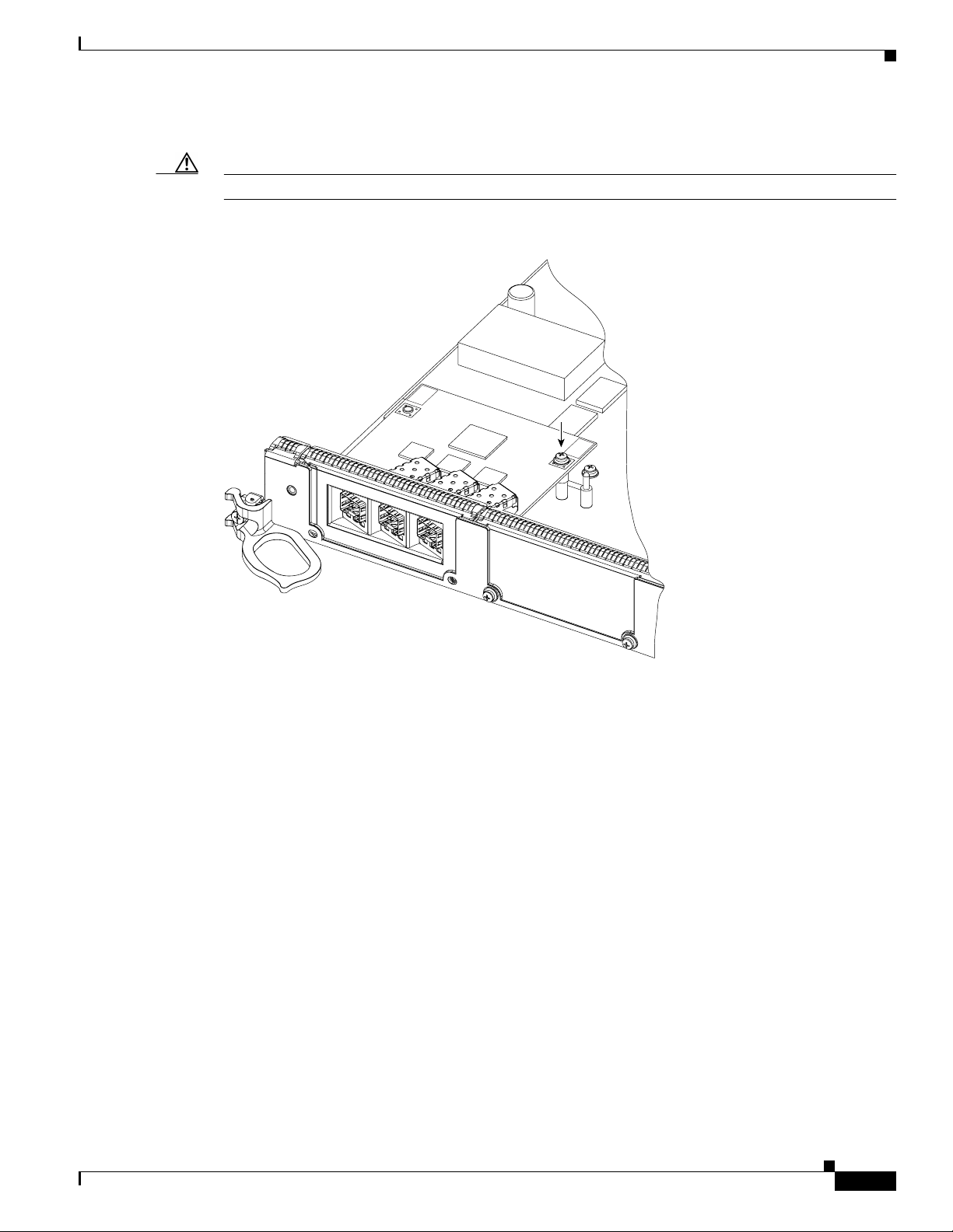
Step 5 Use a Phillips screwdriver to insert and tighten the screwon the EPA,3to 5 in-lbs, as shownin Figure 14.
Caution Apply no more than 5 in-lbs of torque when tightening the screw.
Figure 14 Inserting and Tightening the Screw on the EPA
PUSH
CORNERS
TO
INSTALL
PUSH
CORNERS
TO
INSTALL
129875
OL-7861-01
Cisco XR 12000 Series Router Ethernet Line Card Installation
21
Page 22
Removing and Installing GBICs
Step 6 Use a Phillips screwdriver to insert and tighten the two screws on the faceplate of the line card,
3 to 5 in-lbs, as shown in Figure 15.
Caution Apply no more than 5 in-lbs of torque when tightening the screw.
Figure 15 Inserting the 2 screws on the Faceplate of the Line Card
PUSH
CORNERS
TO
INSTALL
PUSH
CORNERS
TO
INSTALL
Removing and Installing GBICs
Your Ethernet line card may have shipped with a GBIC installed. If your line card arrived without the
GBIC installed and you need to install it now, or if you need to change your GBIC for another reason,
use the procedures in these sections:
• General GBIC Handling and Maintenance Guidelines, page 23
• Removing the GBIC from an Ethernet Line Card, page 23
• Inserting a GBIC into the Gigabit Ethernet Interface, page 24
Before you remove or install a GBIC, read the installation information in this section and the “Laser
Safety” section on page 81.
Note Cisco strongly recommends that you disconnect all fiber-optic cables before removing or installing a
GBIC.
129856
22
Cisco XR 12000 Series Router Ethernet Line Card Installation
OL-7861-01
Page 23

Caution To prevent system problems, do not use GBICs from third-party vendors. Use only the GBIC that
shipped with your Gigabit Ethernet line card. These GBICs might contain an internal EPROM that
identifies them to the Cisco IOS software.
Caution To prevent problems associated with data transmission, you must attach this device only to
IEEE 802.3x-compliant devices.
Note The Ethernet line card supports online insertion and removal (OIR) of GBICs. This means that you can
remove and replace GBICs while the system remains powered up. When you remove a GBIC, the
interface becomes inactive because a GBIC is not detected in the GBIC receptacle.
General GBIC Handling and Maintenance Guidelines
Follow these GBIC handling and maintenance guidelines:
• GBICs are static sensitive. To prevent ESD damage, follow the guidelines described in the
“Preventing Electrostatic Discharge” section on page 9.
• GBICs are dust sensitive. When the GBIC is stored or when a fiber-optic cable is not plugged into
one of the optical ports on the GBIC, always insert an optical port dust plug.
• Keep the optical port clean. The most common source of contamination in the optical ports is debris
that collects on the ferrules of the optical cable connectors. Use an alcohol swab or Kim-Wipe to
clean the ferrules of the cable connector before inserting it into the GBIC.
Removing and Installing GBICs
Removing the GBIC from an Ethernet Line Card
To remove the GBIC from an Ethernet line card, follow these steps:
Step 1 Disconnect the SC-type fiber-optic cables from the GBIC. Note which plug is TX and which plug is RX
for reattachment.
Step 2 Attach an ESD wrist or ankle strap and follow its directions for use.
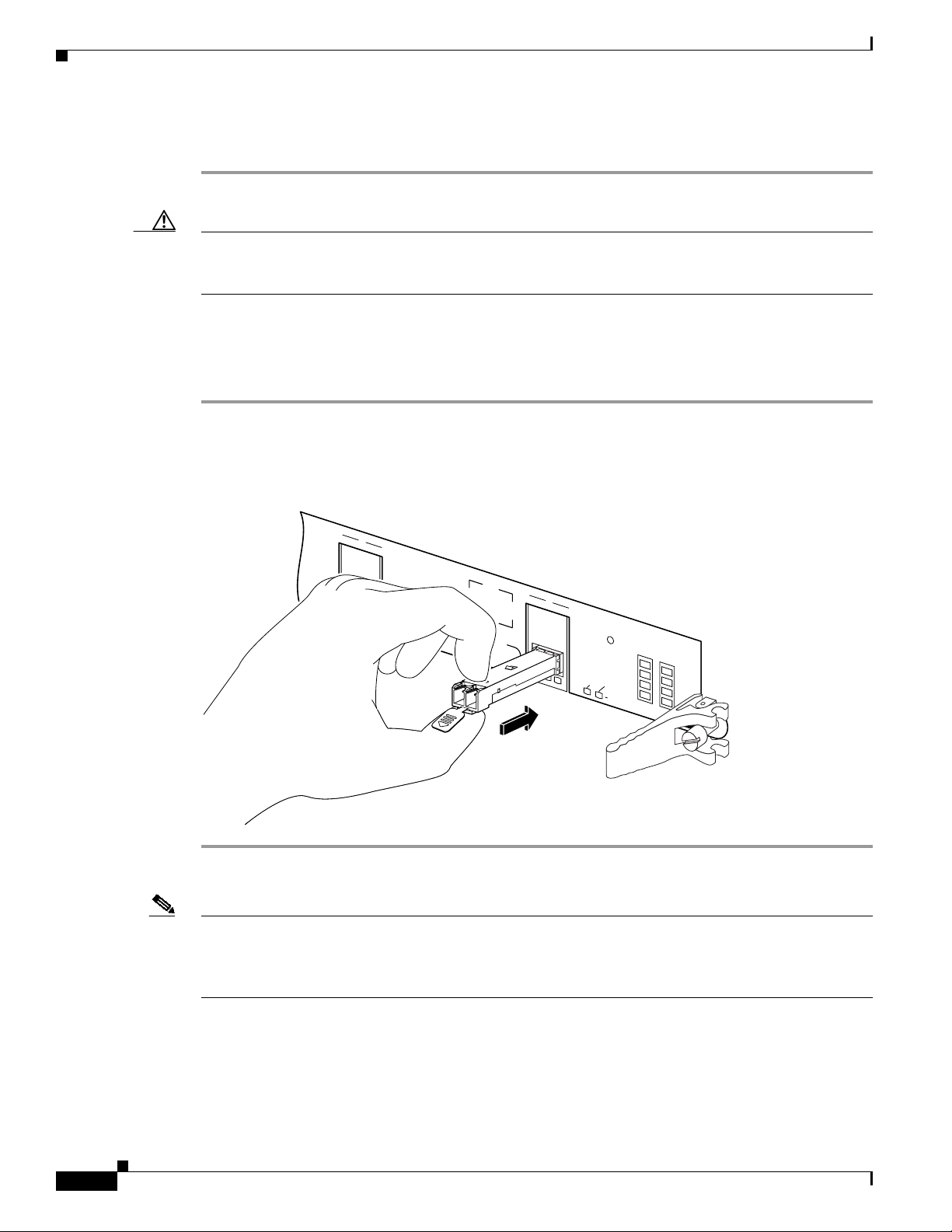
Step 3 Locate the tabs on either side of the exposed portion of the GBIC and squeeze them with your thumb
and forefinger, as you gently pull the GBIC out of the GBIC slot. (See arrows in Figure 16.)
OL-7861-01
Cisco XR 12000 Series Router Ethernet Line Card Installation
23
Page 24
Removing and Installing GBICs
Figure 16 Removing and Replacing a GBIC
3
98896
1 Locking tab 2 Locking tab 3 Alignment groove
Inserting a GBIC into the Gigabit Ethernet Interface
To insert a GBIC into the Gigabit Ethernet interface, follow these steps:
Step 1 Attach an ESD wrist or ankle strap and follow its directions for use.
Step 2 Locate the alignment groove on the GBIC. (See the enlargement in Figure 16 on page 24.) Position the
GBIC so that this groove is in the position shown in the enlargement to ensure that the 20-pin plug on
the GBIC is in the correct position.
Caution To prevent damage to the GBIC plug and receptacle before you insert the GBIC into the GBIC slot on
the Gigabit Ethernet interface, ensure that the plug and alignment groove are matched.
Step 3 Squeeze the tabs on each side of the GBIC using your thumb and forefinger, and insert the GBIC into
the GBIC slot on the Gigabit Ethernet interface. (See Figure 16 on page 24.)
24
Cisco XR 12000 Series Router Ethernet Line Card Installation
OL-7861-01
Page 25
Step 4 Using moderate force, ensure that the GBIC is fully inserted into the 20-pin receptacle at the rear of the
GBIC slot. The tabs on either side of the GBIC will snap into place when you have completely and
properly inserted the GBIC.
Step 5 Reattach the SC-type fiber-optic cable to the GBIC.
Removing and Installing SFP Modules
Before you remove or install an SFP module, read the installation information in this section and the
“Laser Safety” section on page 81.
Caution Protect the SFP modules by inserting clean dust covers into them after the cables are removed. Be sure
to clean the optic surfaces of the fiber cables before you plug them back into the optical ports of another
SFP module. Avoid getting dust and other contaminants into the optical ports of your SFP modules,
because the optics will not work correctly when obstructed with dust.
Removing and Installing SFP Modules
Caution It is strongly recommended that you do not install or remove the SFP module with fiber-optic cables
attached to it because of the potentialof damaging the cable, the cable connector, or the optical interfaces
in the SFP module. Disconnect all cables before removing or installing an SFP module.
Removing and inserting an SFP module can shorten its useful life, so you should not remove and insert
SFP modules any more often than is absolutely necessary.
SFP modules use one of four different latching devices to install and remove the module from a port.
The four types of SFP module latching devices are described in the following sections:
• Bale Clasp SFP Module, page 25
• Mylar Tab SFP Module, page 28
• Actuator Button SFP Module, page 30
• Slide Tab SFP Module, page 33
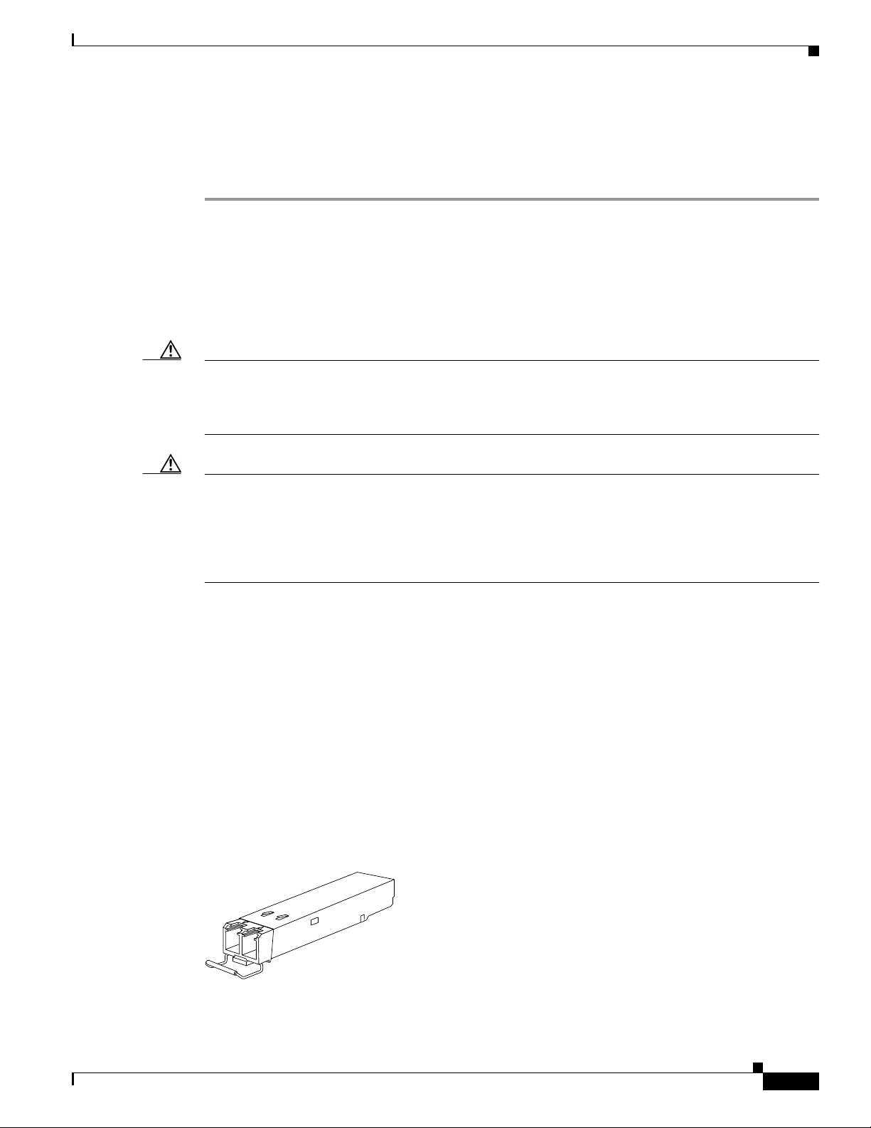
Bale Clasp SFP Module
The bale clasp SFP module has a clasp that you use to removeor install the SFP module. (See Figure 17.)
Figure 17 Bale Clasp SFP Module
OL-7861-01
63067
Cisco XR 12000 Series Router Ethernet Line Card Installation
25
Page 26

Removing and Installing SFP Modules
Removing a Bale Clasp SFP Module
To remove this type of SFP module, follow these steps:
Step 1 Attach an ESD-preventive wrist or ankle strap and follow its instructions for use.
Step 2 Disconnect and remove all interface cables from the ports; note the current connections of the cables to
the ports on the line card.
Step 3 Open the bale clasp on the SFP module with your index finger in a downward direction, as shown in
Figure 18. If the bale clasp is obstructed and you cannot use your index finger to open it, use a small
flat-blade screwdriver or other long, narrow instrument to open the bale clasp.
Step 4 Grasp the SFP module between your thumb and index finger and carefully remove it from the port, as
shown in Figure 18.
26
Cisco XR 12000 Series Router Ethernet Line Card Installation
OL-7861-01
Page 27
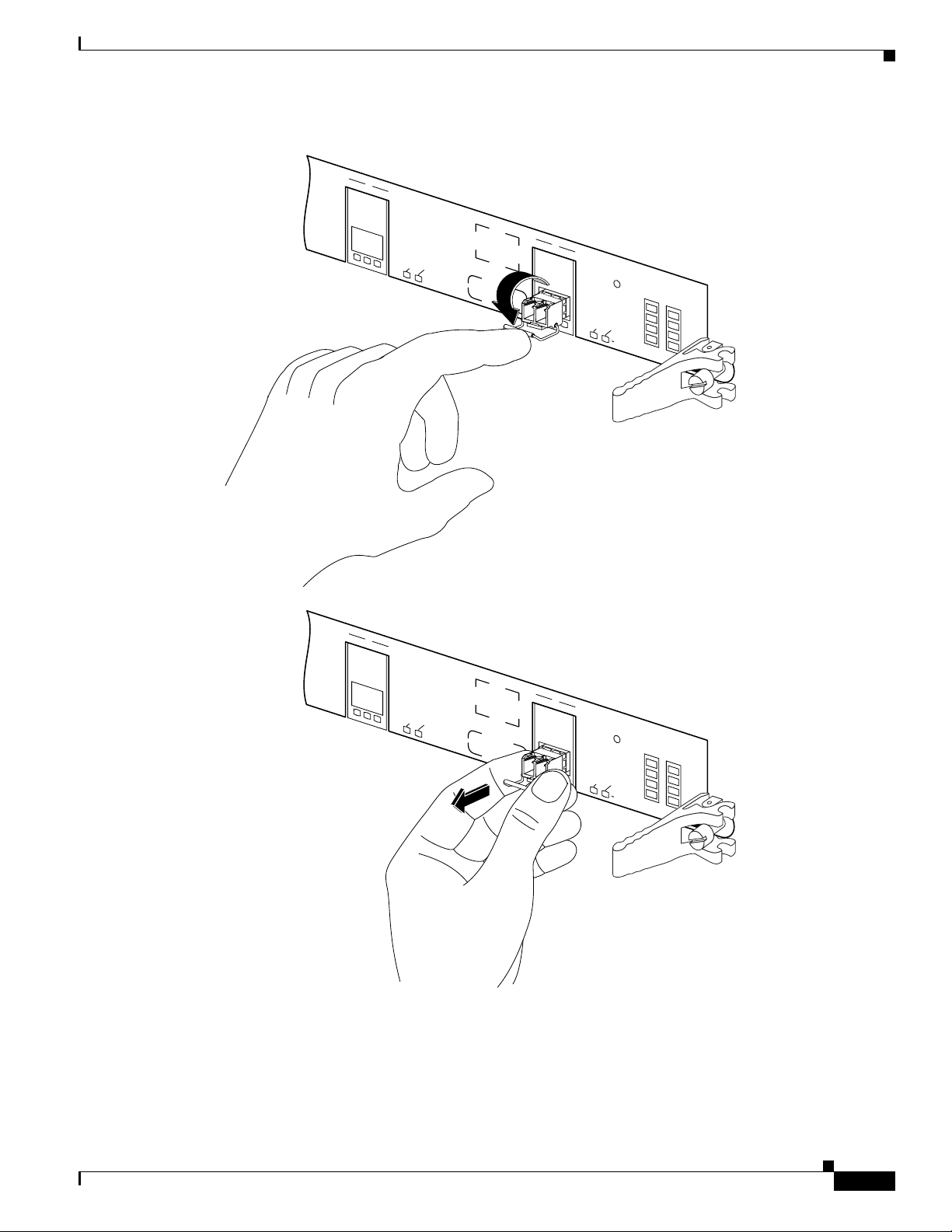
Figure 18 Removing a Bale Clasp SFP Module
2
ACTIVE
CARRIER
RX PACKET
PASS THRU
WRAP
3
ACTIVE
CARRIER
RX PACKET
PASS THRU
WRAP
4OC48/SRP-SFP
Removing and Installing SFP Modules
2
ACTIVE
CARRIER
RX PACKET
3
PASS THRU
WRAP
ACTIVE
CARRIER
RX PACKET
PASS THRU
WRAP
4OC48/SRP-SFP
84508
Step 5 Place the removed SFP module on an antistatic mat, or immediately place it in a static shielding bag if
you plan to return it to the factory.
OL-7861-01
Cisco XR 12000 Series Router Ethernet Line Card Installation
27
Page 28

Removing and Installing SFP Modules
Step 6 Protect your line card by inserting clean SFP module cage covers into the optical module cage when
there is no SFP module installed.
Installing a Bale Clasp SFP Module
To install this type of SFP module, follow these steps:
Step 1 Attach an ESD-preventive wrist or ankle strap and follow its instructions for use.
Step 2 Close the bale clasp before inserting the SFP module.
Step 3 Line up the SFP module with the port and slide it into the port. (See Figure 19.)
Figure 19 Installing a Bale Clasp SFP Module into a Port
ACTIVE
2
CARRIER
RX PACKET
PASS THRU
WRAP
ACTIVE
3
CARRIER
RX PACKET
Note Verify that the SFP modules are completely seated and secured in their assigned receptacles on the line
card by firmly pushing on each SFP module. If the SFP module was not completely seated and secured
in the receptacle, you will hear a click as the triangular pin on the bottom of the SFP module snaps into
the hole in the receptacle.
Mylar Tab SFP Module
The mylar tab SFP module has a tab that you pull to remove the module from a port. (See Figure 20.)
PASS THRU
WRAP
4OC48/SRP-SFP
84507
28
Cisco XR 12000 Series Router Ethernet Line Card Installation
OL-7861-01
Page 29

Figure 20 Mylar Tab SFP Module
Removing a Mylar Tab SFP Module
To remove this type of SFP module, follow these steps:
Step 1 Attach an ESD-preventive wrist or ankle strap and follow its instructions for use.
Step 2 Disconnect and remove all interface cables from the ports; note the current connections of the cables to
the ports on the line card.
Step 3 Pull the tab gently in a slightly downward direction until it disengages from the port, then pull the SFP
module out. (See Figure 21.)
Removing and Installing SFP Modules
63065
Figure 21 Removing a Mylar Tab SFP Module
2
ACTIVE
CARRIER
RX PACKET
PASS THRU
WRAP
ACTIVE
3
CARRIER
RX PACKET
PASS THRU
WRAP
4OC48/SRP-SFP
84504
OL-7861-01
Step 4 Place the removed SFP module on an antistatic mat, or immediately place it in a static shielding bag if
you plan to return it to the factory.
Cisco XR 12000 Series Router Ethernet Line Card Installation
29
Page 30
Removing and Installing SFP Modules
Step 5 Protect your line card by inserting clean SFP module cage covers into the optical module cage when
there is no SFP module installed.
Caution When pulling the tab to remove the SFP module, be sure to pull in a straight outward motion so you
remove the SFP module from the port in a parallel direction. Do not twist or pull the tab, because you
might disconnect it from the SFP module.
Installing a Mylar Tab SFP Module
To install this type of SFP module, follow these steps:
Step 1 Attach an ESD-preventive wrist or ankle strap and follow its instructions for use.
Step 2 Line up the SFP module with the port, and slide it into place. (See Figure 22.)
Figure 22 Installing a Mylar Tab SFP Module
2
ACTIVE
CARRIER
RX PACKET
PASS THRU
WRAP
ACTIVE
3
CARRIER
RX PACKET
PASS THRU
WRAP
4OC48/SRP-SFP
84503
Note Verify that the SFP modules are completely seated and secured in their assigned receptacles on the line
card by firmly pushing on each SFP module. If the SFP module was not completely seated and secured
in the receptacle, you will hear a click as the triangular pin on the bottom of the SFP module snaps into
the hole in the receptacle.
Actuator Button SFP Module
The actuator button SFP module includes a button that you push in order to remove the SFP module from
a port. (See Figure 23.)
Cisco XR 12000 Series Router Ethernet Line Card Installation
30
OL-7861-01
Page 31

Figure 23 Actuator Button SFP Module
Removing an Actuator Button SFP Module
To remove this type of SFP module, follow these steps:
Step 1 Attach an ESD-preventive wrist or ankle strap and follow its instructions for use.
Step 2 Disconnect and remove all interface cables from the ports; note the current connections of the cables to
the ports on the line card.
Step 3 Gently press the actuator button on the front of the SFP module until it clicks and the latch mechanism
activates, releasing the SFP module from the port. (See Figure 24.)
Removing and Installing SFP Modules
63066
OL-7861-01
Cisco XR 12000 Series Router Ethernet Line Card Installation
31
Page 32

Removing and Installing SFP Modules
Figure 24 Removing an Actuator Button SFP Module from a Port
ACTIVE
2
CARRIER
RX PACKET
PASS THRU
WRAP
ACTIVE
3
CARRIER
RX PACKET
PASS THRU
WRAP
4OC48/SRP-SFP
2
ACTIVE
CARRIER
RX PACKET
3
PASS THRU
WRAP
ACTIVE
CARRIER
RX PACKET
PASS THRU
WRAP
4OC48/SRP-SFP
84506
Step 4 Grasp the actuator button between your thumb and index finger and carefully pull the SFP module from
the port.
Step 5 Place the removed SFP module on an antistatic mat, or immediately place it in a static shielding bag if
you plan to return it to the factory.
32
Cisco XR 12000 Series Router Ethernet Line Card Installation
OL-7861-01
Page 33

Step 6 Protect your line card by inserting clean SFP module cage covers into the optical module cage when
there is no SFP module installed.
Installing an Actuator Button SFP Module
To install this type of SFP module, follow these steps:
Step 1 Attach an ESD-preventive wrist or ankle strap and follow its instructions for use.
Step 2 Line up the SFP module with the port and slide it in until the actuator button clicks into place. (See
Figure 25.) Be sure not to press the actuator button as you insert the SFP module because you might
inadvertently disengage the SFP module from the port.
Figure 25 Installing an Actuator Button SFP Module
2
Removing and Installing SFP Modules
Note Verify that the SFP modules are completely seated and secured in their assigned receptacles on the line
card by firmly pushing on each SFP module. If the SFP module was not completely seated and secured
in the receptacle, you will hear a click as the triangular pin on the bottom of the SFP module snaps into
the hole in the receptacle.
Slide Tab SFP Module
ACTIVE
CARRIER
RX PACKET
PASS THRU
WRAP
ACTIVE
3
CARRIER
RX PACKET
PASS THRU
WRAP
4OC48/SRP-SFP
84505
OL-7861-01
The slide tab SFP module has a tab underneath the front of the SFP module that you use to disengage
the module from a port. (See Figure 26.)
Cisco XR 12000 Series Router Ethernet Line Card Installation
33
Page 34

Removing and Installing SFP Modules
Figure 26 Slide Tab SFP Module
Removing a Slide Tab SFP Module
To remove this type of SFP module, follow these steps:
Step 1 Attach an ESD-preventive wrist or ankle strap and follow its instructions for use.
Step 2 Disconnect and remove all interface cables from the ports; note the current connections of the cables to
the ports on the line card.
Step 3 Grasp the SFP module between your thumb and index finger.
Step 4 With your thumb, push the slide tab on the bottom front of the SFP module in the direction of the line
card to disengage the module from the line card port. (See Figure 27.)
84651
Figure 27 Disengaging the Slide Tab
84652
34
Step 5 With the tab still pushed, carefully pull the SFP module from the port as shown in Figure 28.
Caution You must disengage the SFP module by pushing on the slide tab before you can pull out the SFP module.
If you pull on the SFP module without disengaging the tab, you can damage the SFP module.
Cisco XR 12000 Series Router Ethernet Line Card Installation
OL-7861-01
Page 35

Removing and Installing SFP Modules
Figure 28 Removing a Slide Tab SFP Module
3
ACTIVE
CARRIER
RX PACKET
PASS THRU
WRAP
4OC48/SRP-SFP
84650
Step 6 Place the removed SFP module on an antistatic mat, or immediately place it in a static shielding bag if
you plan to return it to the factory.
Step 7 Protect your line card by inserting clean SFP module cage covers into the optical module cage when
there is no SFP module installed.
Installing a Slide Tab SFP Module
To install this type of SFP module into a line card, follow these steps:
Step 1 Attach an ESD-preventive wrist or ankle strap and follow its instructions for use.
Step 2 Hold the SFP module with the hardware label facing up.
Caution The SFP module must be inserted with the hardware label facing up to avoiding damaging the module
or the line card.
Step 3 Insert the SFP module into the appropriate slot and gently push on it until it snaps into the slot tightly.
(See Figure 29.)
OL-7861-01
Cisco XR 12000 Series Router Ethernet Line Card Installation
35
Page 36

Line Card Cable-Management Bracket
Figure 29 Installing a Slide Tab SFP Module
ACTIVE
2
CARRIER
RX PACKET
PASS THRU
WRAP
ACTIVE
3
CARRIER
RX PACKET
PASS THRU
WRAP
4OC48/SRP-SFP
84649
Note Verify that the SFP modules are completely seated and secured in their assigned receptacles on the line
card by firmly pushing on each SFP module. If the SFP module was not completely seated and secured
in the receptacle, you will hear a click as the triangular pin on the bottom of the SFP module snaps into
the hole in the receptacle.
Line Card Cable-Management Bracket
Note The illustrations in this section show various line cards, but the line card cable-management bracket
installation procedure is the same regardless of the specific line card.
Cisco XR 12000 Series Routers include a cable-management system that organizes the interface cables
entering and exiting the router, keeping them out of the way and free of sharp bends.
Caution Excessive bending of interface cables can damage the cables.
The cable-management system consists of two separate components:
1. A cable-management tray that is mounted on the chassis. Refer to the appropriate Cisco XR 12000
Series Router installation and configuration guide for more information on the cable-management
tray.
36
Cisco XR 12000 Series Router Ethernet Line Card Installation
OL-7861-01
Page 37

Line Card Cable-Management Bracket
2. A cable-management bracket that attaches to a line card.
This section describes the line card cable-management bracket. Figure 30 shows the single-port line card
cable-management bracket; Figure 31 shows the multiport line card cable-management bracket.
Figure 30 Single-Port Line Card Cable-Management Bracket
93237
Figure 31 Multiport Line Card Cable-Management Bracket
93238
OL-7861-01
Note When shipped with spare line card orders, the cable-management bracket is not attached to the line card.
You must attach the cable-management bracket to the line card before you insert the line card into the
router.
Cisco XR 12000 Series Router Ethernet Line Card Installation
37
Page 38

Line Card Cable-Management Bracket
Caution Do not use the cable-management bracket as a handle to pull out or push in the line card. The
cable-management bracket is designed to hold the interface cables and may break if you use the bracket
to push, pull, or carry the line card after it is removed from the router.
Removing and installing the line card cable-management bracket is described in the following
procedures:
• Removing a Line Card Cable-Management Bracket, page 38
• Installing a Line Card Cable-Management Bracket, page 40
Removing a Line Card Cable-Management Bracket
To remove a line card cable-management bracket, follow these steps:
Step 1 Attach an ESD-preventive wrist or ankle strap and follow its instructions for use.
Step 2 Note the current interface cable connections to the ports on each line card.
Step 3 Starting with the interface cable for the bottom port on the line card, disconnect the cable from the line
card interface.
Note It is not necessary to remove the interface cables from the line card cable-management bracket. The
bracket (with attached cables) can be hooked to the cable-management tray or a bracket on the chassis
until a new line card is installed.
Step 4 For multiport line card cable-management brackets, proceed upward and remove the interface from the
Velcro strap on the end of the cable standoff. (See Figure 32.)
Forsingle-port line card cable-management brackets, carefully remove the interface cable from thecable
clip. (See Figure 33.) Avoid any kinks or sharp bends in the cable.
Step 5 Repeat Step 3 and Step 4 for all remaining interface cables, then proceed to Step 6.
Step 6 For multiport line card cable-management brackets, loosen the captive installation screw at each end of
the cable-management bracket and remove the bracket from the line card.
For single-port line card cable-management brackets, loosen the captive installation screw on the
cable-management bracket and remove the bracket from the line card.
38
Cisco XR 12000 Series Router Ethernet Line Card Installation
OL-7861-01
Page 39

Line Card Cable-Management Bracket
Figure 32 Multiport Line Card Cable-Management Installation and Removal
(4-Port OC-48c/STM-16c DPT Line Card Shown)
a
b
1
WITH ALCOHOL
WIPES BEFORE
CONNECTING
CLEAN
CONNECTOR
01
ACTIVE
CARRIER
RX PACKET
PASS THRU
WRAP
CLASS 1 LASER PRODUCT
LASERPRODUKT DER KLASSE 1
PRODUIT LASER DE CLASSE 1
PRODUCTO LASER DE CLASSE 1
ACTIVE
CARRIER
RX PACKET
PASS THRU
WRAP
ACTIVE
CARRIER
RX PACKET
PASS THRU
WRAP
2
3
4
2
WITH ALCOHOL
WIPES BEFORE
CONNECTING
CLEAN
CONNECTOR
01
ACTIVE
CARRIER
RX PACKET
PASS THRU
WRAP
CLASS 1 LASER PRODUCT
LASERPRODUKT DER KLASSE 1
PRODUIT LASER DE CLASSE 1
PRODUCTO LASER DE CLASSE 1
ACTIVE
CARRIER
RX PACKET
PASS THRU
WRAP
2
ACTIVE
CARRIER
RX PACKET
PASS THRU
WRAP
ACTIVE
CARRIER
RX PACKET
PASS THRU
WRAP
4OC48/SRP-SFP
3
ACTIVE
CARRIER
RX PACKET
PASS THRU
WRAP
4OC48/SRP-SFP
3
80220
1 Chassis cable-management tray 3 Line card cable-management bracket
2 Velcro straps 4 Fiber cable
OL-7861-01
Cisco XR 12000 Series Router Ethernet Line Card Installation
39
Page 40

Line Card Cable-Management Bracket
Figure 33 Single-Port Line Card Cable-Management Bracket Installation and Removal (1-Port
OC-192c/STM-64c DPT Line Card Shown)
1
4
2
3
TX
TX RX
RX
80300
1 Chassis cable-management tray 3 Interface cable
2 Cable clip 4 Line card cable-management bracket
Installing a Line Card Cable-Management Bracket
To install a line card cable-management bracket, follow these steps:
40
Step 1 Attach an ESD-preventive wrist or ankle strap and follow its instructions for use.
Cisco XR 12000 Series Router Ethernet Line Card Installation
OL-7861-01
Page 41

Step 2 Attach the line card cable-management bracket to the line card as follows:
a. Position the cable-management bracket over the front of the line card faceplate.
b. Insert and tighten the captive screw(s) to secure the bracket to the line card.
c. Starting with the bottom port on the line card, connect each interface cable to the intended port.
Step 3 For multiport line card cable-management brackets, carefully wrap the cables with the supplied Velcro
strap. (See Figure 32.)
For single-port line card cable-management brackets, carefully press the interface cable onto the cable
clip. (See Figure 33.) Avoid any kinks or sharp bends in the cable.
For information on disconnecting and connecting interface cables, see the “Removing and Installing
Fiber-Optic Interface Cables” section on page 51.
Cabling and Specifications
The following sections provide information about specifications and cabling for Ethernet line cards:
• Fast Ethernet Interface, page 41
• Gigabit Ethernet Interface, page 43
• Fiber-Optic Interface Cables, page 49
• Removing and Installing Fiber-Optic Interface Cables, page 51
• Cleaning Fiber-Optic Connectors, page 55
• Type RJ-45 100BASE-T Copper Cables, page 56
• Removing and Installing RJ-45 100BASE-T Copper Cable, page 56
Cabling and Specifications
Fast Ethernet Interface
The term Ethernet is commonly used for all carrier sense, multiple access/collision detection
(CSMA/CD) local-area networks (LANs) that conform to Ethernet specifications, including Fast
Ethernet defined by IEEE 802.3u.
IEEE 802.3u specifies the following different physical layers for 100BASE-T:
• 100BASE-TX—100BASE-T, half- and full-duplex over Category 5 unshielded twisted-pair (UTP),
Electronics Industry Association/Telecommunications Industry Association
[EIA/TIA]–568-compliant cable.
Note The 8-Port Fast Ethernet line card provides an RJ-45 connector that follows the
Media-Dependent Interface (MDI) port wiring standard, as opposed to the
Media-Dependent Interface-crossed (MDI-X) wiring scheme found on many hubs and
repeaters.
OL-7861-01
Cisco XR 12000 Series Router Ethernet Line Card Installation
41
Page 42

Cabling and Specifications
Note 100BASE-TX and 100BASE-FX are commonly called 100BASE-X rather than
100BASE-T.
Note The 8-Port Fast Ethernet line cardsupports 100BASE-TXand100BASE-FX.100BASE-T4
is not supported.
Table 8 lists the cabling specifications for 100 Mbps Fast Ethernet transmission over UTP, STP, and
fiber-optic cables. Table 9 summarizes IEEE 802.3u 100BASE-T physical characteristics for
100BASE-TX and 100BASE-FX.
Table 8 Specification and Connection Limits for 100-Mbps Transmission
Parameter RJ-45 MII SC-Type
Cable specification Category 51 UTP2, 22
Maximum cable length – 1.64 ft (0.5 m) (MII-to-MII
Maximum segment
length
Maximum network
length
• 100BASE-FX—100BASE-T, half- and full-duplex over fiber-optic cable.
• 100BASE-T4—100BASE-T, half- and full-duplex over Category 3, 4, or 5 UTP or shielded
twisted-pair (STP) cabling with four pairs, also called 4T+. Two-pairUTP over Category 3 cable is
called T2.
to 24 AWG
3
150-ohm UTP or STP, or
Category 3, 4, or 5,
62.5/125 multimode
fiber-optic
multimode fiber-optic
–
cable4)
328 ft (100 m) for
100BASE-TX
656 ft (200 m)5(with 1
repeater)
1. EIA/TIA-568 or EIA-TIA-568 TSB-36 compliant.
2. Cisco Systems does not supply Category 5 UTP RJ-45 or 150-ohm STP MII cables. Both are available commercially.
3. AWG = American Wire Gauge. This gauge is specified by the EIA/TIA-568 standard.
4. This is the cable between the MII port on the FE interface and the appropriate transceiver.
5. This length is specifically between any two stations on a repeated segment.
3.28 ft (1 m)5 or 1,312 ft
2 km
(400 m) for 100BASE-FX
– 4 km5(with 1
repeater)
42
Table 9 IEEE 802.3u Physical Characteristics
Parameter 100BASE-FX 100BASE-TX
Data rate (Mbps) 100 100
Signaling method Baseband Baseband
Maximum segment length
2 km between repeaters 100 m between DTE1 and repeaters
(meters)
Media SC-type: dual simplex or single
duplex for receive (RX) and
transmit (TX)
Topology Star or hub Star or hub
1. DTE = data terminal equipment.
Cisco XR 12000 Series Router Ethernet Line Card Installation
RJ-45MII
OL-7861-01
Page 43

Gigabit Ethernet Interface
This section describes the Gigabit Ethernet interface:
• GBIC Laser Optical Transceiver Modules, page 43
• Gigabit Ethernet SFP Modules, page 47
• 10-Gigabit Ethernet, page 49
GBIC Laser Optical Transceiver Modules
The Gigabit Interface Converters(GBICs) are field-replaceablemodulesthat plug into receptacles on the
line card and provide the Gigabit Ethernet optical interface. The GBICs have two optical
interfaces—laser transmit (TX) and laser receive (RX)—and an electrical interface (to the line card). All
GBIC module types have dual SC connectors. Different GBICs can be ordered for each port on the line
card. The 1-Port Gigabit Ethernet and 3-Port Gigabit Ethernet line cards use GBICs to provide the
Gigabit Ethernet optical interface.
The following sections provide information on the GBIC and Coarse Wave Division Multiplexing
(CWDM) GBIC in Ethernet line cards:
• GBIC Modules, page 43
• Using CWDM GBICs with the 3-Port Gigabit Ethernet Line Card, page 45
• General CWDM GBIC Installation and Usage Guidelines, page 46
• Related CWDM Documentation, page 46
• General Connection Rules for CWDM GBICs, page 46
Cabling and Specifications
GBIC Modules
Fiber-optic transmission specifications identify two types of fiber: single-mode and multimode. Signals
can travel farther through single-mode fiber than through multimode fiber.
The 1-Port Gigabit Ethernet and 3-Port Gigabit Ethernet line cards support multimode fiber through the
WS-G5484= GBIC laser optical transceiver module and single-mode fiber through the WS-G5486=,
WS-G5487=. The 3-Port Gigabit Ethernet line card also supports CWDM-GBIC-xxxx= GBIC laser
optical transceiver modules.
Table 10 describes the operating parameters for available GBIC laser optics.
Table 10 Ethernet GBIC Laser Optic Parameters
GBIC Module/
Connector Type Wavelength Fiber Type Distance
WS-G5484=
SC connector
WS-G5486=
SC connector
Shortwave (multimode shorthaul)
Defined by 1000BASE-SX
standard, IEEE 802.3
Longwave (single-mode longhaul)
Compliant with 1000BASE-LX
standard, IEEE 802.3
850 nm 62.5 micron MMF 902 feet (275 m)
50 micron MMF 1804 feet (550 m)
1310 nm 10/9 micron SMF 6.2 miles (10 km)
1
OL-7861-01
Cisco XR 12000 Series Router Ethernet Line Card Installation
43
Page 44

Cabling and Specifications
Table 10 Ethernet GBIC Laser Optic Parameters (continued)
GBIC Module/
Connector Type Wavelength Fiber Type Distance
WS-G5487=
SC connector
CWDM-GBIC-x
3
xxx=
1. These distances represent best case conditions, depending on fiber quality, dispersion, and losses due to connectors, nodes,
or splices. In the case of the CWDM GBICs, CWDM OADM modules or mux/demux modules are needed for these GBICs to
work in any topology other than a point-to-point topology within one building, so the maximum distance is determined by an
optical power budget calculation that takes into consideration all sources of loss, including the insertion loss due to the
CWDM OADM and mux/demux modules, and might be different from the distance shown in the table. For optical parameter
information associated with the CWDM OADM and mux/demux modules, see the “Related CWDM Documentation” section
on page 46.
2. Dispersion-shifted single-mode fiber-optic cable required for 100,000-meter distance.
3. Supported by 3-Port Gigabit Ethernet modules
4. The wavelengths of the CWDM GBICs are based on a 20-nanometer (nm) wavelength grid and are available in eight
wavelengths: 1470, 1490, 1510, 1530, 1550, 1570, 1590, and 1610 nm.
Note 1000BASE-SX and 1000BASE-LX (LH) were originally part of the IEEE 802.3z standard, which has
Extended distance (single-mode) 1550 nm 10/9 micron SMF 43.5 miles (70 km)
2
62 miles (100 km)
Longwave (single-mode) 1470-1610
nm
4
8 micron SMF
SMF 10/9 micron 62 miles (100 km)
1
been incorporated into the IEEE 802.3 standard.
Note Use only GBIC modules supplied by Cisco with your Ethernet line card. They have been tested by Cisco
Engineering and, in some cases, a Cisco-supplied GBIC might contain an internal erasable
programmable read-only memory (EPROM) that identifies the GBIC to the Cisco IOS software.
The maximum distance for any fiber span in an optical network is determined by the fiber type and
quality, as well as the span length, number of splices, and number of optical nodes in the path. If your
network design requires the signal to travel close to the theoretical maximum distance (as listed in
Table 11), you must calculate the optical power budget and receive (RX) sensitivity for the entire
network topology to ensure it is within the specifications of the GBIC option in use.
Note Actual power budget calculations involve a number of variablesspecifictonetworktopology and design,
and are therefore outside the scope of this publication.
Table 11 Optical Parameter Values for Calculating Link Power Budget
Transmit
GBIC
WS-G5484= –9.5dBm to 0 dBm2–17 to 0 dBm –17 dBm 7.5 dB 1,804 feet (550 m)
WS-G5486= –11 to –3 dBm –19 to –3 dBm –19 dBm 8 dB 6.2 miles (10 km)
WS-G5487= 0 to +5 dBm –23 to 0 dBm –23 dBm 23 dB 43.5 to 62 miles (70 to
CWDM-GBIC-xxxx= +1 to +5 dBm –31 to –7 dBm –31 dBm 32 dB 62 miles (100 km)
1. These distances represent best case conditions, depending on fiber quality, dispersion, and losses due to connectors, nodes,
or splices.
Power
Receive
Power
Receive
Sensitivity
Link
Budget Maximum Distance
3
100 km
)
4
1
44
Cisco XR 12000 Series Router Ethernet Line Card Installation
OL-7861-01
Page 45

2. dBm = decibels referenced to 1 milliwatt.
3. Dispersion-shifted single-mode fiber-optic cable required for 100-km distance.
4. This distance represents best case conditions, depending on fiber quality, dispersion, and losses due to connectors, nodes, or
splices. In the case of the CWDM GBICs, CWDM OADM modules or mux/demux modules are needed for these GBICs to
work in any topology other than a point-to-point topology within one building, so the maximum distance is determined by an
optical power budget calculation that takes into consideration all sources of loss, including the insertion loss due to the
CWDM OADM and mux/demux modules, and might be different from the distance shown in the table. For optical parameter
information associated with the CWDM OADM and mux/demux modules, see the “Related CWDM Documentation” section
on page 46.
Using CWDM GBICs with the 3-Port Gigabit Ethernet Line Card
The 3-Port Gigabit Ethernet line card supports CWDM GBICs. The eight CWDM GBICs available for
use with an Ethernet line card are active components that plug into standard GBIC receptacles in the line
card. They convert Gigabit Ethernet electrical signals into an optical single-mode fiber (SMF) interface
that feeds into a CWDM network through a Cisco optical add/drop multiplexing (OADM) plug-in
module or multiplexing/demultiplexing (mux/demux) plug-in module. Figure 34 shows the physical
appearance of a CWDM GBIC with one optical port dust plug removed.
Figure 34 CWDM GBIC (Yellow-Coded CWDM-GBIC-1550= Shown)
Cabling and Specifications
7
1
CWDM-GBIC-1550=
1000BASE-CWDM GBIC
SINGLE-MODE
2
6
5
4
3
84472
1 Color band on label 4 Transmit optical bore 6 Receive optical bore
2 Alignment groove 5 Optical bore dust plug 7 Color dot
3 Spring clip
The eight CWDM GBICs available for use with a Gigabit Ethernet line card come in eight wavelengths
in a range from 1470 nm to 1610 nm. The color dot between the receiveand transmit ports and the color
band on the label of the Cisco CWDM GBIC identify the wavelength of the GBIC. Table 12 lists the
CWDM GBICs and their associated color codes.
Table 12 Gigabit Ethernet CWDM GBIC Laser Optic Parameters
OL-7861-01
GBIC Product Number CWDM GBIC Wavelength Color Identifier
CWDM-GBIC-1470= Longwave 1470 nm laser single-mode Gray
CWDM-GBIC-1490= Longwave 1490 nm laser single-mode Violet
CWDM-GBIC-1510= Longwave 1510 nm laser single-mode Blue
CWDM-GBIC-1530= Longwave 1530 nm laser single-mode Green
Cisco XR 12000 Series Router Ethernet Line Card Installation
45
Page 46

Cabling and Specifications
Table 12 Gigabit Ethernet CWDM GBIC Laser Optic Parameters (continued)
GBIC Product Number CWDM GBIC Wavelength Color Identifier
CWDM-GBIC-1550= Longwave 1550 nm laser single-mode Yellow
CWDM-GBIC-1570= Longwave 1570 nm laser single-mode Orange
CWDM-GBIC-1590= Longwave 1590 nm laser single-mode Red
CWDM-GBIC-1610= Longwave 1610 nm laser single-mode Brown
General CWDM GBIC Installation and Usage Guidelines
The Cisco CWDM GBIC solution has two main components: the Cisco CWDM GBICs and the Cisco
OADM plug-in modules or mux/demux plug-in modules, which are rack mounted in a Cisco CWDM
OADM chassis external to the Cisco 12000 Series Router that contains the Ethernet line card.
The CWDM OADM plug-in modules and mux/demux plug-in modules are passive optical components
that multiplex together multiple wavelengths from multiple SMF fiber pairs into one SMF fiber pair. Up
to two CWDM plug-in modules can be rack-mounted by using the single-rack-unit CWDM chassis.
The CWDM GBICs plug into the standard GBIC receptacles on the faceplate of the Ethernet line card
and are connected to the CWDM OADM or mux/demux plug-in modules in the external CWDM chassis
using SMF jumper cables with SC-type connectors.
A Cisco 12000 Series Router equipped with an Ethernet line card and CWDM GBICs can be connected
into a CWDM networkthrough external CWDM plug-in modules in the following deployment scenarios:
• Point-to-point—Two endpoints are directly connected via a fiber link. You can add or drop up to
eight Gigabit Ethernet channels into a pair of single-mode fibers.
• Hub-and-spoke (ring)—Multiple nodes (spokes) are connected with a hub location through a ring
of single-mode fiber. Each hub/node connection can consist of one or more wavelengths, each
carrying a full Gigabit Ethernet channel.
• Mesh (ring)—Combines the hub-and-spoke and point-to-point (or even multiple point-to-point)
connections in parallel on the same CWDM optic link. The maximum of eight GBIC wavelengths
allows different combinations of these scenarios.
Related CWDM Documentation
For more information about CWDM GBIC solution deployment, including the optical parameters
(insertion loss and isolation values) for the CWDM OADM and mux/demux plug-in modules, see the
following related documentation:
• Cisco CWDM GBIC Solution, Data Sheet
• Cisco CWDM GBIC Solution, Q & A
• Installation Note for the CWDM Passive Optical System
General Connection Rules for CWDM GBICs
Observe the following connection rules for CWDM GBICs:
• Always match the CWDM GBIC color with the equipment port of the same color on the CWDM
passive optical system plug-in module.
Use the CWDM passive optical system connectorcolor codes shown in Table 12 to help you connect
your router to the CWDM passive optical system.
Cisco XR 12000 Series Router Ethernet Line Card Installation
46
OL-7861-01
Page 47

• Always connect from transmit (TX) to receive (RX) when connecting GBICs to other equipment:
–
Connect GBIC TX to equipment RX
–
Connect GBIC RX to equipment TX
• Optical transceivers—such as the Cisco CWDM GBICs—have a maximum optical receive power,
above which damage might occur to the receivediode. The incoming power level might be too high
if the fiber lacks sufficient attenuation, which might occur in a short run of fiber (less than
approximately 25 km). Attenuators are used to lower the incoming optical signal below the
maximum optical receive power of the Cisco CWDM GBIC (–7 dB).
• When the length of the fiber-optic link is less than 15.5 miles (25 km),you must insert a 10-dB inline
optical attenuator (Cisco product number AT-10DB-SC=) between the fiber-optic network and the
receivingport on the Cisco CWDMGBIC at each end ofthe link to ensure that the maximum receive
power is always less than –7 dBm.
Gigabit Ethernet SFP Modules
The Gigabit Ethernet laser optical transceiver module is a field-replaceable small form-factor pluggable
(SFP) module that plugs into the receptacle on the Ethernet port adapter (EPA) located on the Modular
Ethernet line card and provides the Gigabit Ethernet optical interface. (See Figure 35.) The module has
two optical interfaces—laser transmit (TX) and laser receive (RX)—and an electrical interface (to the
line card). The 4-Port Gigabit Ethernet ISE, 10-Port 1-Gigabit Ethernet, and Modular Gigabit Ethernet
line cards use SFP modules.
Cabling and Specifications
Figure 35 SFP Module and Fiber-Optic Cable
CSA ID
PA-0
PA-1
PA-2
ACTIVE
LINK
0
RX PKT
EPA-3GE/SX/LH-LC
1
2
ACTIVE
LINK
0
RX PKT
2
EPA-3GE/SX/LH-LC
1
2
1
3
98895
OL-7861-01
1 Component side of line card 3 Card carrier side of line card
2 Top surface of SFP module
Cisco XR 12000 Series Router Ethernet Line Card Installation
47
Page 48

Cabling and Specifications
The following SFP module options are available for a Gigabit Ethernet line card:
• GLC-SX-MM—Short wavelength SFP module (850 nm nominal), for use in 1000BASE-SX links.
• GLC-LH-SM—Long-haul or long-wavelength SFP module (1310 nm nominal), for use in
1000BASE-LX links.
• GLC-LX-SM—Single-mode, long-reach
• GLC-ZX-SM=—Single-mode, extended-reach (supported by 4-Port Gigabit Ethernet ISE line card
only)
The SFP modules have LC connectors. Different SFP module options allow you to customize the
physical interfaces on the line card by using both types of modules on the same line card. The only
restriction is that each port must match the specifications on the other end of the cable (short or long
wavelength), and must not exceed the recommended cable length for reliable communication.
Fiber-optic transmission specifications identify two types of fiber: single-mode and multimode. The
maximum distance for single-mode installations is determined by the amount of light loss in the fiber
path. If your environment requires the light to travel close to the typical maximum distance, you should
use an optical time domain reflectometer (OTDR) to measure the power loss.
Table 13 describes the operating parameters for the supported SFP modules.
Table 13 Gigabit Ethernet SFP Module Power Budget and Signal Requirements
Power
SFP Transceiver
GLC-SX-MM Short wavelength
Multimode,
GLC-LH-SM
GLC-LX-SM
GLC-ZX-SM
1. dBm = decibels referenced to 1 milliwatt
2. nm = nanometer
3. Not valid for 4-Port Gigabit Ethernet ISE line card
4. 4-Port Gigabit Ethernet ISE line card only
5. 4-Port Gigabit Ethernet ISE line card only
3
4
5
short haul
Long wavelength
Single-mode,
long haul
Single-mode,
long-reach
Single-mode,
extended-reach
Table 14 Gigabit Ethernet Laser Optical Transceiver (SFP) Module Operating Parameters
Budget
7.5 dB –9.5 to -4 dBm
8.0 dB –9.5 to –3 dBm
8 dB –11 to –3 dBm
23 dB 0 to +5 dBm
SFP Module Type Wavelength Cable Distance
GLC-SX-MM Short wavelength
(multimode short haul)
GLC-LH-SM Long wavelength
(single-mode long
haul)
Transmit
Power
at 850 nm
at 1310 nm
at 1310 nm
at 1550 nm
Receive
Power
1
2
–17 to 0 dBm –17 dBm 984 feet (300 meters)
–19 to -3 dBm 32,808 feet (10,000 meters)
–19 to –3 dBm –19 dBm
–23 to 0 dBm –23 dBm
850 nm MMF 62.5/125 micron 722 feet (220 m)
MMF 50/125 micron 1640 feet (500 m)
1310 nm SMF 9/125 micron 32,808 feet (10,000 m)
Receive
Sensitivity
Typical Maximum
Distance
48
Cisco XR 12000 Series Router Ethernet Line Card Installation
OL-7861-01
Page 49

Note Use only the SFP modules supplied by Cisco with your Gigabit Ethernet line card. Each SFP module
contains an internal serial EEPROM that is security-programmed by the SFP manufacturer with
information that provides a way for Cisco (through the Cisco IOS software) to identify and validate the
SFP module as a module type that was tested and qualified by Cisco to operate properly with Cisco
Gigabit Ethernet line cards. UnapprovedSFPmodules (those not purchased directlyfrom Cisco) will not
work on the Gigabit Ethernet line card.
10-Gigabit Ethernet
The 1-Port 10-Gigabit Ethernet line card uses single-mode fiber-optic cable. The maximum distance for
single-mode installations is determined by the amount of light loss in the fiber path. If your environment
requires the light to travel close to the typical maximum distance (as listed in Table 16), you should use
an optical time domain reflectometer (OTDR) to measure the power loss.
The Ethernet line card is offered in two transceiver options:
Table 15 describes the operating parameters for the transceiver options.
Cabling and Specifications
• Long haul or long wavelength, 1310 nanometers (nm) nominal, used for 1000BASE-LR links.
• Long haul or long wavelength, 1550 nm nominal, used for 1000BASE-ER links.
Table 15 10-Gigabit Ethernet Laser Optical Transceiver Operating Parameters
Transceiver Option Type Wavelength Cable Distance
LR Long wavelength
(single-mode long haul)
ER Long wavelength
(single-mode long haul)
1310 nm SMF 9/125 micron 6.2 miles (10 km)
1550 nm SMF 9/125 micron 24.9 miles (40 km)
Table 16 lists the power ratings and maximum distances of both models of the Ethernet line cards. The
actual distance in any given case depends on the quality of the fiber connected to the transceiver.
Table 16 Transceiver Module Power Budget and Signal Requirements
Power
Transceiver Option
LR 6.2 dB –8.2 to +0.5 dBm at 1310 nm –14.4 to +0.5 dBm 6.2 miles (10 km)
ER 11.1 dB –4.7 to +4 dBm at 1550 nm –15.8 to –1 dBm 24.9 miles (40 km)
Budget
Transmit
Power
Receive
Power Typical Maximum Distance
Fiber-Optic Interface Cables
Depending on the line card (refer to Table 4 on page 4), use a single-mode or multimode fiber-optic
interface cable with LC-type or SC-type connectors to connect an Ethernet interface on the Ethernet line
card in your Cisco XR 12000 Series Router to another Ethernet interface, router, or switch.
OL-7861-01
Note Fiber optic cables are not available from Cisco Systems. They can be purchased from cable vendors.
The following types of cables are used with Ethernet line cards to connect your router to another router
or switch:
Cisco XR 12000 Series Router Ethernet Line Card Installation
49
Page 50

Cabling and Specifications
Note For network applications using CWDM GBICs in Ethernet line cards, the CWDMGBICs use SMF patch
cords only. Verify that all your patch cords are yellow (SMF), rather than orange (MMF).
The following types of cable connectors are used with Ethernet line cards:
You can use two cables with simplex connectors, or one cable with dual, keyed connectors.
• Single-mode—Generally yellow in color.
• Multimode—Generally gray or orange in color. Multimode cables are multifiber cables that carry
12 channels of fiber data.
• Subscriber connector (SC)—See Figure 36 and Figure 37
• Lucent connector (LC)— See Figure 38 and Figure 39
Warning
Invisible laser radiation can be emitted from the aperture of the port when no cable is connected.
Avoid exposure to laser radiation and do not stare into open apertures.
Figure 36 Simplex SC Cable Connector (Single-mode)
1 2
66917
1 SC cable connector 2 Spring-action disconnect latch
Figure 37 Duplex SC Cable Connector
H2214
50
Cisco XR 12000 Series Router Ethernet Line Card Installation
OL-7861-01
Page 51

Figure 38 Simplex LC Cable Connector
2
Cabling and Specifications
1
75894
1 LC connector 2 Spring-action disconnect latch
Figure 39 Duplex LC Cable Connector
30929
57653
TX RX
Note Connectors on the fiber-opticcables must be free of dust,oil, or other contaminants. Before
connecting the cable to the line card, carefully clean the fiber-optic connectors using an
alcohol wipe or other suitable cleanser. Refer to the “Cleaning Fiber-Optic Connectors”
section on page 55 for more information.
The connector on the cable might be supplied with a dust cover. If it is, remove the dust
cover before trying to connect the cable to the line card port.
Removing and Installing Fiber-Optic Interface Cables
This section contains informationon removing and installing fiber-optic interface cables to connect your
router to another router or switch.
Note The procedures in the following sections use illustrations of an Ethernet line card to support the
descriptions of removing and installing interface cables. Although the line cards differ, the process of
removing and installing interface cables is basically the same. Therefore, separate procedures and
illustrations are not included in this publication.
Cisco XR 12000 Series Router Ethernet Line Card Installation
OL-7861-01
51
Page 52

Cabling and Specifications
Removing Fiber-Optic Interface Cables
To remove line card interface cables, refer to Figure 40 (showing one possible arrangement) and follow
these steps:
Step 1 Attach an ESD-preventive wrist or ankle strap to your wrist and follow its instructions for use.
Step 2 Press on the spring-action disconnect latch to disconnect the interface cable connectors from the line
card interface ports.
Warning
Invisible laser radiation can be emitted from the aperture of the port when no cable is connected.
Avoid exposure to laser radiation and do not stare into open apertures.
Note You do not have to remove the interface cables from the line card cable-management bracket.
Step 3 Insert a dust plug into the optical port openings of each port that is not being used.
Step 4 Use a screwdriver to loosen the captive installation screws at the ends of the line card cable-management
bracket.
Step 5 Detach the line card cable-management bracket and optical fiber cable bundle from the line card and
place it carefully out of the way. (See Figure 40B.)
52
Cisco XR 12000 Series Router Ethernet Line Card Installation
OL-7861-01
Page 53

Figure 40 Disconnecting Line Card Interface Cables
Cabling and Specifications
a
WITH ALCOHOL
WIPES BEFORE
CONNECTING
CLEAN
CONNECTOR
01
ACTIVE
CARRIER
RX PACKET
PASS THRU
WRAP
CLASS 1 LASER PRODUCT
LASERPRODUKT DER KLASSE 1
PRODUIT LASER DE CLASSE 1
PRODUCTO LASER DE CLASSE 1
1
b
WITH ALCOHOL
WIPES BEFORE
CONNECTING
CLEAN
CONNECTOR
01
ACTIVE
CARRIER
RX PACKET
PASS THRU
WRAP
CLASS 1 LASER PRODUCT
LASERPRODUKT DER KLASSE 1
PRODUIT LASER DE CLASSE 1
PRODUCTO LASER DE CLASSE 1
2
PASS THRU
WRAP
ACTIVE
CARRIER
RX PACKET
PASS THRU
WRAP
ACTIVE
CARRIER
RX PACKET
4
PASS THRU
WRAP
2
ACTIVE
CARRIER
RX PACKET
PASS THRU
WRAP
2
ACTIVE
CARRIER
RX PACKET
3
3
ACTIVE
CARRIER
RX PACKET
PASS THRU
WRAP
4OC48/SRP-SFP
1 Fiber cable 3 Cable-management bracket 5 SFP module
2 Velcro strap 4 Dust plug
Installing Fiber-Optic Interface Cables
Use two simplex SC or LC connectors or one duplex SC or LC connector (refer to Figure 41 on page 54
and Figure 42 on page 55).
Note Optical fiber cables are availablefromcable vendors. These cables are not available from Cisco Systems.
Warning
Invisible radiation may be emitted from the aperture of the port when no fiber cable is
connected, so avoid exposure to radiation and do not stare into open apertures.
ACTIVE
CARRIER
RX PACKET
PASS THRU
WRAP
4OC48/SRP-SFP
3
ACTIVE
2
CARRIER
RX PACKET
80223
5
OL-7861-01
Cisco XR 12000 Series Router Ethernet Line Card Installation
53
Page 54

Cabling and Specifications
Warning
Warning
Class 1 laser product.
Class 1 LED product (multimode).
Note Connectors on the fiber-opticcables must be free of dust,oil, or other contaminants. Before
connecting the cable to the line card, carefully clean the fiber-optic connectors using an
alcohol wipe or other suitable cleanser. Refer to the “Cleaning Fiber-Optic Connectors”
section on page 55 for more information.
To install a cable, follow these steps:
Step 1 Remove the connector dust cover if one is present.
Step 2 Align the connector end of the cable to the appropriate port. Observe the receive (RX) and transmit (TX)
cable relationship on the cables, as shown in Figure 41 and Figure 42.
Step 3 Attach fiber cable between the port in the line card and the device to which the line card is connected.
Step 4 Insert the fiber cable connector until it clicks and locks into place.
Step 5 Repeat these steps until all cabling is complete.
Figure 41 Attaching Simplex or Duplex Fiber Cables (SFP Module)
3
1
2
LINK
ACTIVE
RX FRAME
4
80224
1 2 30
Top surface of
SFP module
Card carrier
side of line card
PASS THRU
WRAP
ACTIVE
CARRIER
RX PACKET
2
Component side
of line card
Gasket edge of
front panel
57654
1 TX connector 3 Simplex cables
2 RX connector 4 Duplex cable
54
Cisco XR 12000 Series Router Ethernet Line Card Installation
OL-7861-01
Page 55

Cabling and Specifications
Figure 42 Attaching Simplex or Duplex Fiber Cables (Line Card Port or GBIC)
Duplex
Simplex
RX
TX
TX
FAST ETHERNET
Simplex
Note The fiber-optic connectors must be free of dust, oil, or other contaminants. Carefully clean the fiber-
optic connectors using an alcohol wipe or other suitable cleanser.
Cleaning Fiber-Optic Connectors
Fiber-optic connectors are used to connect two fibers together. When these connectors are used in a
communication system, proper connection becomes a critical factor. They can be damaged by improper
cleaning and connection procedures. Dirty or damaged fiber-optic connectors can result in
communication that is inaccurate or not repeatable.
Fiber-optic connectors differ from electrical or microwave connectors. In a fiber-optic system, light is
transmitted through an extremely small fiber core. Because fiber cores are often 62.5 microns or less in
diameter, and dust particles range from a tenth of a micron to several microns in diameter, dust and any
other contamination at the end of the fiber core can degrade the performance of the connector interface
where the two cores meet. Therefore, the connector mustbeprecisely aligned and the connector interface
must be absolutely free of foreign material.
Connector loss, or insertion loss, is a critical performance characteristic of a fiber-optic connector.
Return loss is also an important factor. Return loss specifies the amount of reflected light: the lower the
reflection, the better the connection. The best physical contact connectors have return losses of better
than –40 dB, but –20 to –30 dB is more common.
The connection quality depends on two factors: the type of connector and the proper cleaning and
connection techniques. Dirty fiber connectors are a common source of light loss. Keep the connectors
clean at all times, and keep the dust plugs or covers installed when the connectors are not in use.
Before installing any type of cable or connector, use a lint-free alcohol pad from a cleaning kit to clean
the ferrule, the protective tube or cone that surrounds the fiber core, and the end-face surface of the fiber
core.
As a general rule, any time you detect a significant, unexplained loss of light, clean the connectors. To
clean the optical connectors, use a CLETOP fiber optic cleaning cassette (Type A for SC connectors)
and follow the manufacturer’s usage instructions.
RX
Duplex
17464
22553
OL-7861-01
If a CLETOP cleaning cassette is not available, follow these steps:
Cisco XR 12000 Series Router Ethernet Line Card Installation
55
Page 56

Cabling and Specifications
Step 1 Use a lint-free tissue soaked in 99 percent pure isopropyl alcohol and gently wipe the end-face of the
fiber core. Wait 5 seconds for the surfaces to dry and wipe the surfaces a second time.
Step 2 Use clean, dry, oil-free compressed air to remove any residual dust from the connector.
Warning
Step 3 Use a magnifying glass or inspection microscope to inspect the ferrule at angle. Do not look directly into
Invisible laser radiation can be emitted from the aperture of the port when no cable is connected.
Avoid exposure to laser radiation and do not stare into open apertures.
the aperture. If you detect any contamination, repeat Step 1 and Step 2.
Type RJ-45 100BASE-T Copper Cables
For an 8-Port Fast Ethernet line card with RJ-45 ports, use an EIA/TIA–568-compliant cable with MDI
wiring and RJ-45 connectors to connect your Cisco XR 12000 Series Router to another router or switch.
Figure 43 shows a typical RJ-45 connector.
Note EIA/TIA–568-compliant cable with MDI wiring and RJ-45 connectors are available from a wide variety
of sources. These cables are not available from Cisco Systems.
Figure 43 RJ-45 Cable Connector
8 7 6 5 4 3 2 1
RJ-45 connector
H2936
Removing and Installing RJ-45 100BASE-T Copper Cable
This section contains information on removing and installing RJ-45 copper cables to connectyour router
to another router or switch.
Removing RJ-45 Cables
To remove line card cables, follow these steps (refer to Figure 44 on page 57):
Step 1 Attach an ESD-preventive wrist or ankle strap to your wrist and follow its instructions for use.
Step 2 Disconnect the interface cable connectors from the line card interface ports.
Note You do not have to remove the interface cables from the line card cable-management bracket.
Cisco XR 12000 Series Router Ethernet Line Card Installation
56
OL-7861-01
Page 57

Step 3 Use a screwdriver to loosen the captive installation screws at the ends of the line card cable-management
bracket.
Step 4 Detach the line card cable-management bracket and optical fiber cable bundle from the line card and
place it carefully out of the way.
Installing RJ-45 Cables
Insert the RJ-45 connector into an open port until the connector clicks and locks into place. Attach one
cable between each line card interface and the device to which the line card is connected. Figure 44
shows the relationship between the RJ-45 interface on the line card and the cable connector.
Figure 44 Attaching RJ-45 Copper Cables
Verifying and Troubleshooting the Installation
FAST ETHERNET
25059
Verifying and Troubleshooting the Installation
After installing the hardware, you need to look at the LEDs to verify that the Ethernet line card was
installed correctly. If it was not, you need to troubleshoot to find the problem. The following sections
provide information about how to verify and troubleshoot line card installations:
• Initial Boot Process, page 57
• Status LEDs, page 58
• Alphanumeric LEDs, page 59
• Troubleshooting the Installation, page 63
Initial Boot Process
Note Many new line cards are designated as administratively down by default. Status LEDs are off until you
configure the interfaces and use the no shutdown command.
OL-7861-01
Cisco XR 12000 Series Router Ethernet Line Card Installation
57
Page 58

Verifying and Troubleshooting the Installation
During a typical line card boot process, the following events occur:
1. The line card maintenance bus (MBus) module receives power and begins executing the MBus
software.
2. The line card MBus module determines the type of card on which it resides, performs internal
checks, and prepares to accept the Cisco IOS software from the RP.
3. The RP powers up the line card and loads the line card with its Cisco IOS software.
To verify that the line card is working properly, perform the following operational checks:
• During the line card boot process, observe the line card alphanumeric LEDs to ensure that the card
is running the typical initialization sequence. The sequence should end with IOS RUN.
• Observe the line card status LEDs to verify that the Active LED (Link LED or status LED for line
cards with no Active LED) is on. If an Active LED is not on, verify that the associated interface is
not shut down.
Status LEDs
The Gigabit Ethernet line cards and the 8-Port Fast Ethernet line card have different status LEDs.
Gigabit Ethernet Status LEDs
After installing the line card and connecting the interface cables, verify that the line card is working
properly by observing the LEDs on the faceplate. For the locations of the LEDs, refer to the figures in
the “Product Overviews” section on page 4.
Status LEDs show the status of each fiber-optic connector:
• LINK—When lit, indicates that the Gigabit Ethernet (GE) MAC layer is receiving comma characters
from a connected GE device.
• ACTIVE—When lit, indicates that the interface is active.
• RX FRAME—When lit, indicates that the interface has received a packet.
Alphanumeric LEDs explain the state of the line card and are made up of two, four-digit alphanumeric
LED displays. (See the “Alphanumeric LEDs” section on page 59.)
The status LEDs might not go on until after you have configured the line card interfaces (or turned them
on, if they were shut down).
The different operating states of the status LEDs on the Gigabit Ethernet line card are shown in Table 17.
58
Cisco XR 12000 Series Router Ethernet Line Card Installation
OL-7861-01
Page 59

Table 17 Status LED Descriptions
LED Color/Activity Description
LINK
ACTIVE
RX FRAME
Green
Off
Green
Off
Green Packets are being received on this interface.
Off Packets are not being received on this interface.
• A signal is detected.
• There is RX synchronization.
• The GBIC or SFP module is inserted and has no fault conditions.
• The line card is connected to another functioning Gigabit Ethernet interface
and has received comma-detect characters.
• Loss of signal (LOS). Occurs when the signal is lost at the optical input. For
example, removing a GBIC or SFP or removing a cable causes both an LOS
and a loss of synchronization.
• Loss of RX synchronization. Occurs when the receiver cannot detect
commas. For example, removing the local RX cable or the remote TX cable
will cause loss of synchronization.
• Invalid word received. To maintain receiver alignment and synchronization,
the receiver looks for a unique detectable code-bit pattern. An invalid word
condition occurs because the receiver detects an incorrect or unsupported
character or sequence of characters, resulting in a loss of synchronization
and a link down condition.
• When the line protocol is up. For example, you enter a no shutdown
command as part of the interface configuration.
• During the line card hardware initialization sequence.
• The line is down because of a link failure or problem with the GBIC or SFP
module.
• Hardware initialization fails.
• The line card interface is shut down, because a GBIC or SFP module was
removed and replaced or was administratively shut down. Note that a newly
inserted line card is designated administrativelydown, so the Active LED for
the interface remains offuntiltheinterfaceis configured. The ActiveLEDon
the line carddoesnotgoonuntil you configure the linecardinterface(orturn
the interface on if it was shut down). As an operational check, you can verify
that the card is receiving power by looking at the alphanumeric display
LEDs, which go on when a line card is inserted correctly into the chassis and
is powered on.
Verifying and Troubleshooting the Installation
Alphanumeric LEDs
Ethernet line cards have two four-digit alphanumeric LED displays at one end of the faceplate, near the
ejector lever, that display a sequence of messages indicating the state of the card. In general, the LEDs
do not turn on until the RP recognizes and powers up the card. As it boots, the line card displays a
sequence of messages similar to those in Table 18.
Note It is normal for some displayed messages to appear too briefly to be read. Also, some messages listed in
Table 18 and Table 19 may not appear on your line card.
OL-7861-01
Cisco XR 12000 Series Router Ethernet Line Card Installation
59
Page 60

Verifying and Troubleshooting the Installation
Table 18 Alphanumeric LED Messages During a Typical Initialization Sequence
LED Display
MROM
nnnn
LMEM
TEST
LROM
RUN
BSS
INIT
RST
SAVE
IO
RST
EXPT
INIT
TLB
INIT
CACH
INIT
MEM
INIT
LROM
RDY
ROMI
GET
ROM
2
VGET
FABI
WAIT
FABM
2
WAIT
FABL
DNLD
FABL
STRT
FABL
RUN
IOS
DNLD
IOS
2
FABW
1
Meaning Source
MBus microcode execute; nnnn is the microcode version
MBus controller
number.
Low memory on the line card is being tested. Line card ROM
monitor
Low memory test has been completed. Line card ROM
monitor
Main memory is being initialized. Line card ROM
monitor
Contents of the reset reason register are being saved. Line card ROM
monitor
Reset I/O register is being accessed. Line card ROM
monitor
Interrupt handlers are being initialized. Line card ROM
monitor
TLB is being initialized. Line card ROM
monitor
CPU data and instruction cache is being initialized. Line card ROM
monitor
Size of the main memory on the line card is being discovered. Line card ROM
monitor
ROM is ready for the download attempt. Line card ROM
monitor
ROM image is being loaded into line card memory. RP IOS software
ROM image is receiving a response. RP IOS software
Line card is waiting for the fabric downloader to load.
Line card is waiting for the fabric manager to report that the
3
RP IOS software
RP IOS software
fabric is usable.
Fabric downloader is being loaded into line card memory. RP IOS software
Fabric downloader is being launched. RP IOS software
Fabric downloader has been launched and is running. RP IOS software
Cisco IOS software is being downloaded into line card
RP IOS software
memory.
Cisco IOS software is waiting for the fabric to be ready. RP IOS software
60
Cisco XR 12000 Series Router Ethernet Line Card Installation
OL-7861-01
Page 61
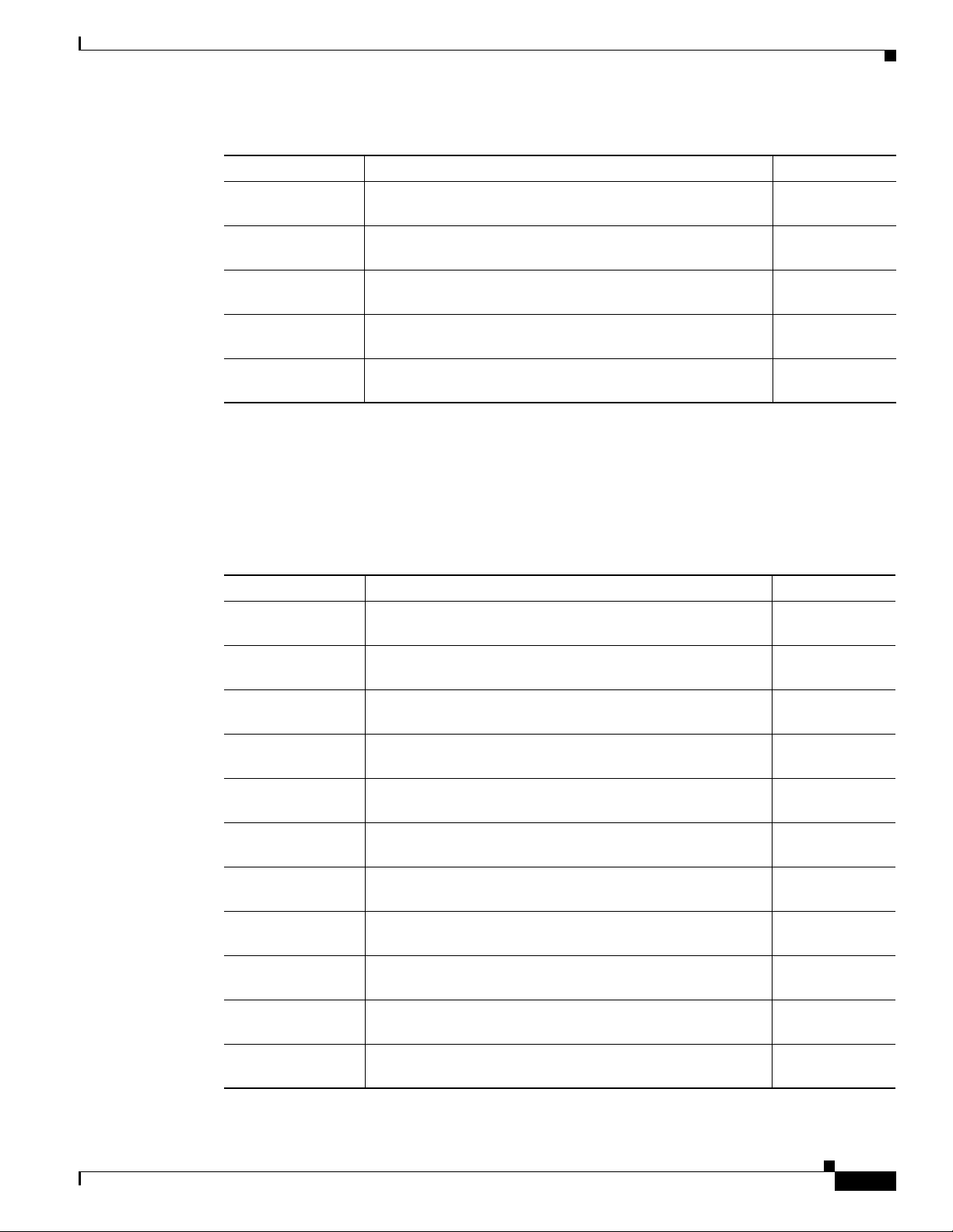
Verifying and Troubleshooting the Installation
Table 18 Alphanumeric LED Messages During a Typical Initialization Sequence (continued)
LED Display
IOS
VGET
IOS
1
Meaning Source
Line card is obtaining the Cisco IOS version. RP IOS software
2
Line card is enabled and ready for use. RP IOS software
RUN
IOS
Cisco IOS software is being launched. RP IOS software
STRT
IOS
Cisco IOS software is transitioning to active. RP IOS software
TRAN
IOS
Cisco IOS software is running. RP IOS software
UP
1. The entire LED sequence shown in Table 18 might occur too quickly for you to read; therefore, this sequence is provided in
this tabular form as a baseline for how a line card should function at startup.
2. This LED sequence only appears in Cisco IOS release 12.0(24)S or later.
3. The fabric downloader loads the Cisco IOS software image onto the line card.
Table 19 lists other messages displayed on the line card alphanumeric LED displays.
Table 19 Other Alphanumeric LED Messages
LED Display Meaning Source
MAL
Line card malfunction reported by field diagnostics. RP
FUNC
MISM
ATCH
PWR
STRT
PWR
1
1
Line card type mismatch in paired slots. RP
Line card has been newly powered on. RP
Line card is powered on. RP
ON
IN
In reset. RP
RSET
RSET
Reset complete. RP
DONE
MBUS
MBus agent downloading. RP
DNLD
MBUS
MBus agent download complete. RP
DONE
ROMI
Acquisition of ROM image complete. RP
DONE
MSTR
Waiting for mastership determination. RP
WAIT
CLOK
Waiting for slot clock configuration. RP
WAIT
OL-7861-01
Cisco XR 12000 Series Router Ethernet Line Card Installation
61
Page 62

Verifying and Troubleshooting the Installation
Table 19 Other Alphanumeric LED Messages (continued)
LED Display Meaning Source
CLOK
DONE
FABL
LOAD
IOS
LOAD
BMA
ERR
FIA
ERR
CARV
ERR
DUMP
REQ
DUMP
RUN
DUMP
DONE
DIAG
MODE
DIAG
LOAD
DIAG
F_LD
DIAG
STRT
DIAG
HALT
DIAG
TEST
DIAG
1
PASS
POST
STRT
UNKN
STAT
ADMN
DOWN
1. This LED sequence only appears in Cisco IOS release 12.0(24)S or later.
2. The fabric downloader loads the Cisco IOS software image onto the line card.
Slot clock configuration done. RP
Loading fabric downloader2 complete. RP
Downloading of Cisco IOS software is complete. RP
Cisco IOS software BMA error. RP
Cisco IOS fabric interface ASIC configuration error. RP
Buffer carving failure. RP
Line card requesting a core dump. RP
Line card dumping core. RP
Line card core dump complete. RP
Diagnostic mode. RP
Downloading field diagnostics over the MBus. RP
Downloading field diagnostics over the fabric. RP
Launching field diagnostics. RP
Cancel field diagnostics. RP
Running field diagnostics tests. RP
Field diagnostics were completed successfully. RP
Launching power-on self-test (POST). RP
Unknown state. RP
Line card is administratively down. RP
62
Cisco XR 12000 Series Router Ethernet Line Card Installation
OL-7861-01
Page 63

Troubleshooting the Installation
Note Many new line cards are designated as administratively down by default. Status LEDs are off until you
configure the interfaces and use the no shutdown command.
If the Active LED (Link LED or status LED for line cards with no Active LED) or the alphanumeric
display LEDs on a line card do not go on, there is either a problem with the line card installation or a
hardware failure. To verify that the line card is installed correctly, follow these steps:
Step 1 If the Active LED fails to go on, but the alphanumeric display LEDs on the line card indicate activity,
verify that the initialization sequence ends with IOS RUN. If this is the case, verify that the interface is
not shut down. If it is not, suspect a circuitry problem with the Active LED and contact a service
representative for further assistance.
Step 2 If the Active LED on the line card fails to go on or the alphanumeric display LEDs do not indicate IOS
RUN, check the router connections as follows:
a. Verify that the line card board connector is fully seated in the backplane. Loosen the captive
installation screws and firmlypivotthe ejector leverstowardeach other until both are perpendicular
to the line card faceplate. Tighten the captive installation screws.
b. Verify that all power cords and data cables are firmly connected at both ends.
c. Verify that all memory modules on the card are fully seated and secured to their sockets.
After the line card reinitializes, the Active LED on the line card should go on. If the Active LED goes
on, the installation is complete; if the Active LED does not go on, proceed to the next step.
Step 3 If the Active LED still fails to go on, remove the Ethernet line card and try installing it in another
available line card slot.
• If the Active LED goes on when the line card is installed in the new slot, suspect a failed backplane
port in the original line card slot.
• If the Active LED and alphanumeric display LEDs still do not go on, halt the installation. Contact
a service representative to report the faulty equipment and obtain further instructions.
Step 4 If an error message displays on the console terminal during the line card initialization, see the
appropriate reference publication for error message definitions. If you experience other problems that
you cannot solve, contact a service representative for assistance.
For more information on troubleshooting and diagnostics, refer to the installation and configuration
guide that came with your Cisco 12000 Series Router.
Verifying and Troubleshooting the Installation
OL-7861-01
Step 5
Note If you perform online insertion or removal of the GBIC or SFP without shutting down the
interface, a warning message is displayed on the console device.
Cisco XR 12000 Series Router Ethernet Line Card Installation
63
Page 64

Line Card Memory
Line Card Memory
This section contains information about the following:
• Line Card Memory Locations, page 64
• Removing and Installing Line Card Memory, page 68
You can replace the route memory on Ethernet line cards. Route memory modules are installed into
144-pin small-outline DIMM (SODIMM) sockets. Route memory runs the Cisco IOS software image
and stores the updated network routing tables downloaded from the route processor.
Table 20 provides information about the various hardware engines available with the Ethernet line cards.
The engine determines where the memory is placed.
Table 20 Ethernet Line Card Engines
Ethernet Line Card Hardware Engine
8-Port Fast Ethernet Engine 1
Gigabit Ethernet
3-Port Gigabit Ethernet Engine 2
4-Port Gigabit Ethernet ISE Engine 3, Internet Services Engine (ISE)
10-Port 1-Gigabit Ethernet Engine 4+ Enhanced Services (ES)
1-Port 10-Gigabit Ethernet
Modular Gigabit Ethernet
Line Card Memory Locations
The following sections contain general line card memory information for each Ethernet line card:
• Engine 2 Line Card Memory Locations, page 65
• ISE Line Card Memory Locations, page 65
• Engine 4 Line Card Memory Locations, page 67
• Ethernet Line Card Route Memory Options, page 67
• Ethernet Line Card Packet Memory Options, page 68
Memory removal and installation instructions are found in the “Removing and Installing Line Card
Memory” section on page 68.
64
Cisco XR 12000 Series Router Ethernet Line Card Installation
OL-7861-01
Page 65

Engine 2 Line Card Memory Locations
Figure 45 shows the DIMM socket locations on an Engine 2 line card. This line card is equipped with
eight DIMM sockets:
• Two route memory DIMM sockets
• Two pairs of packet memory DIMM sockets (RX and TX pairs)
• One pointer look-up (PLU) memory DIMM socket (not user serviceable)
• One table look-up (TLU) memory DIMM socket (not user serviceable)
Figure 45 Engine 2 Line Card Memory Locations
Line Card Memory
1
2
3
4
93276
TX RX
ACTIVE
CARRIER
0
RX PKT
6
5
OC-48/POS-SR-SC
8
7
1 Route memory DIMM0 5 Packet memory RX DIMM0
2 Route memory DIMM1 6 Packet memory RX DIMM1
3 Packet memory TX DIMM0 7 PLU DIMM (not user serviceable)
4 Packet memory TX DIMM1 8 TLU DIMM (not user serviceable)
ISE Line Card Memory Locations
Figure 46 shows the small outline DIMM (SODIMM) socketlocations on an ISE line card. This line card
is equipped with 10 SODIMM sockets:
• Two route memory SODIMM sockets
• Four packet memory sockets (not user serviceable)
• Four TLU/PLU memory sockets (not user serviceable)
OL-7861-01
Cisco XR 12000 Series Router Ethernet Line Card Installation
65
Page 66

Line Card Memory
Figure 46 ISE Line Card Memory Locations
4
3
TX RX
CLEAN
WITH ALCOHOL
CONNECTOR
WIPES BEFORE
CONNECTING
0
ACTIVE
TX RX
CARRIER
A
RX PKT
WRAP
PASS THRU
ACTIVE
CARRIER
B
RX PKT
WRAP
CLASS 1 LASER PRODUCT
PASS THRU
LASERPRODUKT DER KLASSE 1
PRODUIT LASER DE CLASSE 1
TX RX
PRODUCTO LASER DE CLASSE 1
1
ACTIVE
TX RX
CARRIER
A
RX PKT
WRAP
PASS THRU
ACTIVE
CARRIER
B
RX PKT
WRAP
PASS THRU
4OC12X/SRP-IR-LC
4
3
2
1
1 Route memory SODIMM0 3 Four packet memory SODIMM sockets (not field serviceable)
2 Route memory SODIMM1 4 Four TLU/PLU memory SODIMM sockets (not field
serviceable)
84998
66
Cisco XR 12000 Series Router Ethernet Line Card Installation
OL-7861-01
Page 67

Engine 4 Line Card Memory Locations
Figure 47 shows the DIMM socket locations on anEngine 4 line card. These linecards are equipped with
five DIMM sockets:
• One route memory small-outline DIMM (SODIMM) socket
• Two pairs of packet memory DIMM sockets (not user serviceable)
The route memory module is installed to a 144-pin SODIMM socket. Route memory runs the Cisco IOS
software image and stores the updated network routing tables downloaded from the route processor.
Figure 47 Engine 4 Line Card Memory Locations
2
Line Card Memory
1
CLEAN
W
ITH
CONNECTOR
ALCO
W
IPES BEFO
HO
CO
L
NNEC
R
E
TING
TX RX
MATE
1 Route memory SODIMM 2 Packetmemory DIMMs (not user serviceable)
Ethernet Line Card Route Memory Options
Route memory runs the Cisco IOS software image and stores updated network routing tables
downloaded from the route processor (RP). Line card route memory ranges from 128 MB to 256 MB.
Table 21 lists the available route memory configurationsand associated product numbers of the memory
modules used for upgrading route memory on Ethernet line cards.
Table 21 Route Memory Configurations for Ethernet Line Cards
Total Route Memory Cisco Product Number DIMM Module Route Memory DIMM Sockets
64 MB MEM-GRP/LC-64=
128 MB MEM-DFT-GRP/LC-128 1 128-MB DIMM DIMM0 or DIMM1
128 MB MEM-GRP/LC-128= 1 128-MB DIMM DIMM0 or DIMM1
256 MB MEM-GRP/LC-256= 2 128-MB DIMMs DIMM0 and DIMM1
256 MB MEM-LC4-256=
1. This option adds a second 64-MB DIMM for a total of 128 MB for line cards that are equipped with 64 MB.
2. This option is only compatible with the 4-Port Ethernet line cards and is for replacement only.
93274
ACTIVE
CLASS 1 LASER PRODUCT
LASERPRODUKT DER KLASSE 1
CARRIER
RX PKT
SYNC
PASS THRU
WRAP
PRODUIT LASER DE CLASSE 1
PRODUCTO LASER DE CLASSE 1
OC192/SRP-SR-SC
2
1
1 64-MB DIMM DIMM0 or DIMM1
1 256-MB SODIMM Varies
2
OL-7861-01
Cisco XR 12000 Series Router Ethernet Line Card Installation
67
Page 68

Line Card Memory
If you are upgrading or replacing line card route and packet memory,refer to the Cisco XR 12000 Series
Router Memory Replacement Instructions publication for installation procedures and the most
up-to-date memory options.
Ethernet Line Card Packet Memory Options
Line card packet memory temporarily stores data packets awaiting switching decisions by the line card
processor. Once the line card processor makes the switching decisions, the packets are propagated into
the router switch fabric for transmission to the appropriate line card.
Table 22 lists the packet memory options for Ethernet line cards.
Table 22 Ethernet Line Card Packet Memory Options
Total Packet Memory
256 MB MEM-LC1-PKT-256= 2 RX 64-MB DIMMs
512 MB (upgrade) MEM-PKT-512-UPG= 2 RX 128-MB DIMMs
1. The SDRAM DIMMs installedin a given buffer (either receive or transmit) must bethe same type and size, but the individual
receive and transmit buffers can operate with different memory capacities.
1
Cisco Product Number DIMM Modules DIMM Sockets
Removing and Installing Line Card Memory
Before beginning the memory replacement procedures in this section, ensure that you have the proper
tools and equipment at hand, and that you are using appropriate ESD-prevention equipment and
techniques. Before removing or installing memory, observe the following guidelines:
• Route memory DIMMs
–
Route memory DIMM0 socket must always be populated.
–
For certain memory configurations, the route memory DIMM1 socket can remain empty.
–
DIMMs must be 3.3V devices.
• Packet memory DIMMs
–
All four DIMM sockets for SDRAM buffer memory must be populated.
–
Both DIMM sockets for a given buffer pair (either those for the transmit buffer or those for the
receive buffer) must be populated with SDRAM DIMMs of the same type and size.
–
Size of the DIMMs in the transmit buffer need not match the size of the SDRAM DIMMs in the
receive buffer.
–
DIMMs must be 3.3V devices.
Instructions are in the following sections:
• Removing a DIMM, page 69
• Installing a DIMM, page 70
• Removing a SODIMM, page 71
2 TX 64-MB DIMMs
2 TX 128-MB DIMMs
RX DIMM0 and RX
DIMM1
TX DIMM0 and TX
DIMM1
RX DIMM0 and RX
DIMM1
TX DIMM0 and TX
DIMM1
68
Cisco XR 12000 Series Router Ethernet Line Card Installation
OL-7861-01
Page 69

Removing a DIMM
Step 1 Attach an ESD-preventive wrist or ankle strap and follow its instructions for use.
Step 2 Place the line card on an antistatic mat so that the faceplate is nearest to you.
Step 3 Locate the DIMM sockets on the line card.
Line Card Memory
• Installing a SODIMM, page 73
• Checking the Installation of Line Card Memory, page 77
To remove a DIMM from a line card, follow these steps:
Note Some line cards use DIMM sockets equipped with dual release levers, as shown in Figure 48;
other line cards use DIMM sockets equipped with a single release lever, as shown in Figure 49.
Both DIMM sockets operate in the same general way.
Figure 48 DIMM Socket with Dual Release Levers
24860
Figure 49 DIMM Socket with Single Release Lever
Step 4 Use the socket release levers to eject the DIMM.
• For a socket with dual release levers(see Figure 48), pull down both levers at the same time to eject
the DIMM.
or
• For a socket with a single release lever (see Figure 49), pull the lever to eject the DIMM.
H6513
OL-7861-01
Caution Handle the edges of the DIMM only.Do not touch the integrated circuit devices on the DIMM, the metal
traces, or fingers, along the edge of the DIMM, or the pins in the DIMM socket.
Cisco XR 12000 Series Router Ethernet Line Card Installation
69
Page 70

Line Card Memory
Step 5 As one end of the DIMM is released, grasp the top corners of the DIMM with the thumb and forefinger
Step 6 Immediately place the DIMM in an antistatic bag to protect it from ESD damage.
Step 7 Repeat Step 4 through Step 6 for any remaining DIMMs that you want to remove.
Installing a DIMM
Note If you are upgrading packet memory, both DIMM sockets of a given pair (either the transmit buffer or
Step 1 Attach an ESD-preventive wrist or ankle strap and follow its instructions for use.
Step 2 Place the line card on an antistatic mat so that the faceplate is nearest to you.
of each hand and pull the DIMM completely out of its socket.
This section contains instructions for installing DIMM memory into a line card.
the receive buffer) must be populated with a DIMM of the same type and size.
To install DIMMs in a line card, follow these steps:
Caution To prevent router and memory problems, all DIMMs installed in the line card must be 3.3V devices.
Step 3 Remove the new DIMM from its protective antistatic bag.
Step 4 Grasp the edges of the DIMM only. Do not touch the integrated circuit devices on the DIMM, the metal
traces, or fingers, along the edge of the DIMM, or the pins in the DIMM socket. (See Figure 50.)
Step 5 To position the DIMM for insertion, orient it at the same angle as the DIMM socket. The two notches
(keys) on the bottom edge of the module ensure that the DIMM edge connector is registered properly in
the socket. (See Figure 50.)
If necessary, rock the DIMM back and forth gently to align it in the socket.
Figure 50 Handling a DIMM
H6507
70
Key
Cisco XR 12000 Series Router Ethernet Line Card Installation
OL-7861-01
Page 71

Caution When inserting DIMMs into a socket, apply firm, but not excessive, pressure. If you damage a DIMM
socket, you must return the line card for repair.
Step 6 Gently insert the DIMM into the socket and push until the DIMM snaps into place and the release lever
is flush against the side of the socket.
Step 7 Verify that the release lever is flush against the side of the socket. If it is not, the DIMM might not be
seated properly. On a socket with dual release levers, both leversshould be flush against the sides of the
DIMM.
If the module appears misaligned, carefully remove it and reseat it,ensuring that the release leverisflush
against the side of the DIMM socket.
Step 8 Repeat Step 3 through Step 7 to install any remaining DIMMs for your memory configuration.
Removing a SODIMM
Line Card Memory
To remove a SODIMM, follow these steps:
Step 1 Attach an ESD-preventive wrist or ankle strap and follow its instructions for use.
Step 2 Place the line card on an antistatic mat so that the faceplate is nearest to you.
Step 3 Locate the route memory socket on the line card.
Step 4 If present, remove the SODIMM retaining clip from the memory module socket. Grasp the latch arm
intersection located on each side of the clip and gently slide the clip out. (See Figure 51.) Save the
retaining clip.
Note Some line cards do not require a retaining clip.
Caution If the retaining clip is bent or damaged, do not attempt to fix or reuse it. This can cause serious damage
to the line card. Each SODIMM replacement ships with a spare retaining clip, in case there is any
damage to the existing clip.
OL-7861-01
Cisco XR 12000 Series Router Ethernet Line Card Installation
71
Page 72
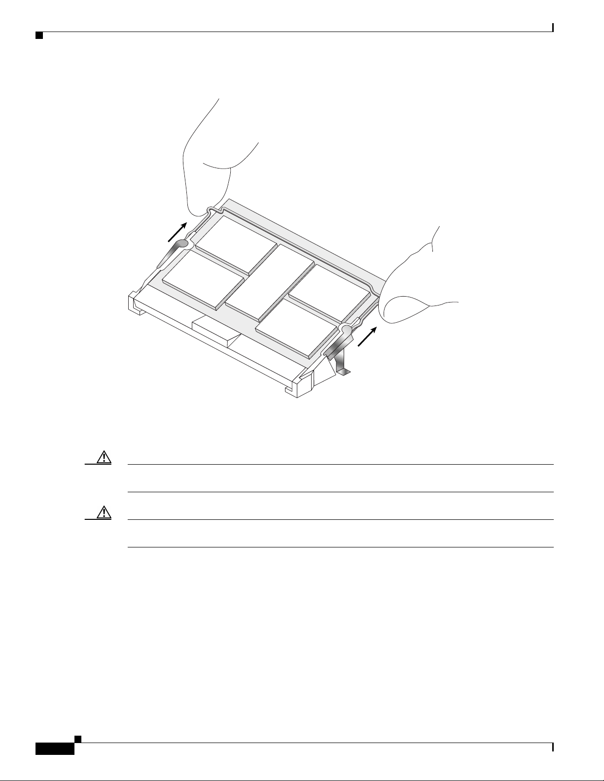
Line Card Memory
Figure 51 Remove Retaining Clip from Memory Module Socket
75779
Step 5 Remove the SODIMM by gently moving the plastic latches in an outward direction, parallel to and away
from the memory module, until it releases and rotates to a 45-degree angle. (See Figure 52 and
Figure 53a.)
Caution The plastic latch on the SODIMM socket is enclosed by the metal strain-relief latch. The plastic latch
should never be moved past the metal strain-relief latch.
Caution Handle the edges of the SODIMM only. Do not touch the integrated circuit devices on the SODIMM,
the metal traces, or fingers, along the edge of the SODIMM, or the pins in the SODIMM socket.
72
Cisco XR 12000 Series Router Ethernet Line Card Installation
OL-7861-01
Page 73

Line Card Memory
Figure 52 Moving the Plastic Latch Away from the SODIMM
75799
Step 6 As the SODIMM is released, it positions itself at a 45-degree angle. Gently pull the SODIMM module
out of the socket. Continue to keep the module at a 45-degree angle until it is completely removed from
the socket guides. (See Figure 53b.)
Figure 53 Removing a 144-pin SODIMM Module
Step 7 Immediately place the SODIMM in an antistatic bag to protect it from ESD damage.
Installing a SODIMM
To install a SODIMM module, follow these steps:
a
º
45
b
75780
OL-7861-01
Step 1 Attach an ESD-preventive wrist or ankle strap and follow its instructions for use.
Step 2 Place the line card on an antistatic mat so that the faceplate is nearest to you.
Step 3 If there is a retaining clip, check to make sure that it has not been damaged or bent. (See Figure 54.)
Cisco XR 12000 Series Router Ethernet Line Card Installation
73
Page 74

Line Card Memory
Caution If the retaining clip is damaged, do not use it. This can damage the SODIMM socket.
Note Some line cards do not require a retaining clip.
Figure 54 SODIMM Socket Retaining Clip
75757
Step 4 Locate the route memory socket on the line card.
Step 5 Remove the new SODIMM from its protective antistatic bag.
Caution Grasp the edges of the SODIMM only. Do not touch the integrated circuit devices on the SODIMM, the
metal traces, or fingers, along the edge of the SODIMM, or the pins in the SODIMM socket.
Step 6 Line up the SODIMM key with the key in the board socket. (See Figure 55.)
Figure 55 SODIMM with Key in Face-Up Position
74
75759
Cisco XR 12000 Series Router Ethernet Line Card Installation
OL-7861-01
Page 75
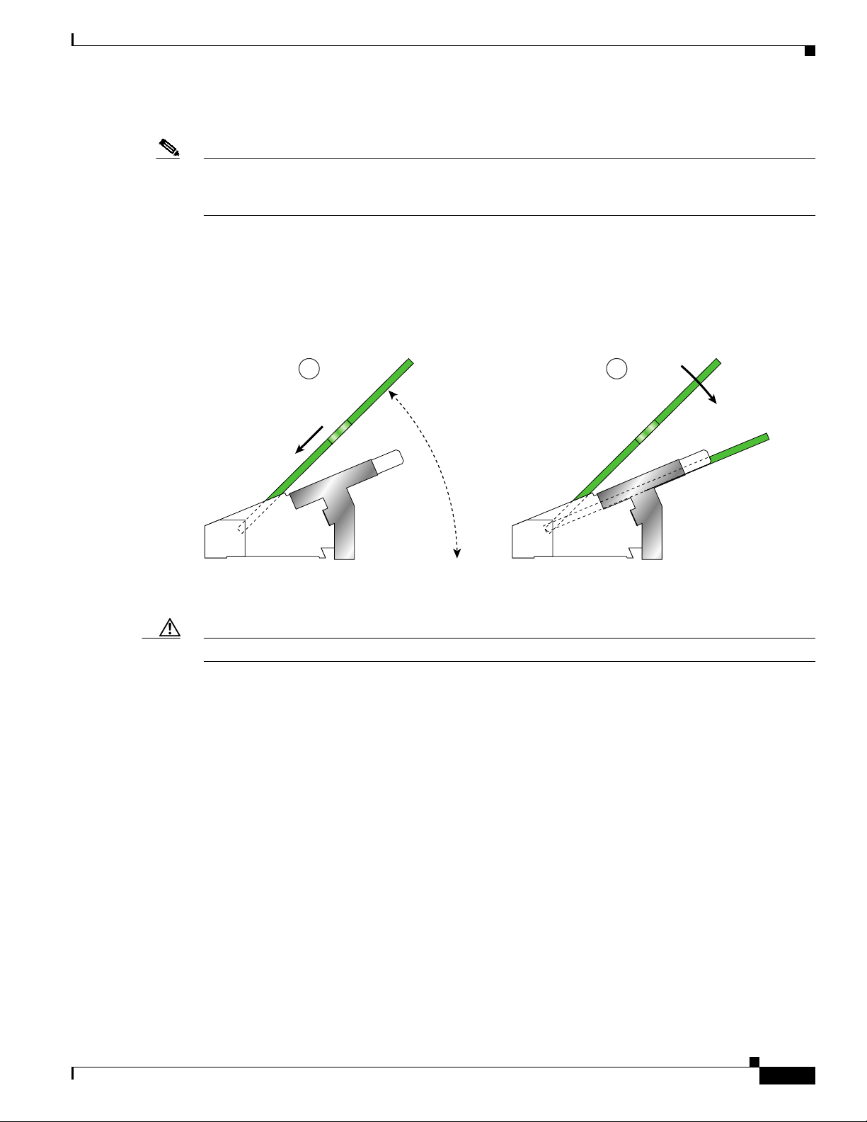
Line Card Memory
Step 7 The SODIMM must be lined up at a 45-degree angle. (See Figure 56a.)
Note When the key is in the face-up position, the metal traces on the left side of the key measure 0.9 inch
(23.20 mm). The metal traces on the right side of the key measure 1.29 inches (32.80 mm). The
SODIMM can not be inserted until the keys are lined up properly.
Step 8 Place both thumbs at the end of the socket and use your index fingers to guide the module into the socket
until it is fully seated.
Be sure your index fingers are located on the outer corners of the SODIMM to maintain even pressure
when the module is being seated in the socket.
Figure 56 Inserting a 144-pin SODIMM Module
a
º
45
Step 9 Gently press the SODIMM down using your index fingers, distributing even pressure across the module
b
66100
until it locks into the tabs. (See Figure 56b.)
Caution Excessive pressure can damage a SODIMM socket.
Step 10 Verify that the release levers are flush against the side of the socket. If they are not, the SODIMM might
not be seated properly.
Step 11 If the module appears misaligned, carefully remove it andreseat it, ensuring that the release leveris flush
against the side of the SODIMM socket.
Step 12 If there is a retaining clip, insert it by sliding the clip between the metal strain relief and the plastic latch.
(See Figure 57.)
OL-7861-01
Cisco XR 12000 Series Router Ethernet Line Card Installation
75
Page 76

Line Card Memory
Figure 57 Inserting the Retaining Clip
75758
The clip is properly installed when the clip detente protrudes below the strain relief and plastic latch.
(See Figure 58.)
76
Cisco XR 12000 Series Router Ethernet Line Card Installation
OL-7861-01
Page 77

Figure 58 Retaining Clip Completely Installed into Module Latch
Line Card Memory
Checking the Installation of Line Card Memory
After you install line card memory and reinstall the line card in the router, the router reinitializes the line
card and detects the memory change as part of the reinitialization cycle. The time required for the router
to initialize can vary with different router configurations and memory configurations.
If the line card does not reinitialize properly after you upgrade memory, or if the console terminal
displays a checksum or memory error, verify that you installed the correct DIMMs and that they are
installed correctly on the line card.
To check the installation of line card memory, follow these steps:
Step 1 Check the packet memory DIMMs toverifythat both DIMMs are the sametype, size, and speed. DIMMs
must operate at 60 ns or faster. The speed of the DIMM is printed along one of its edges.
Step 2 Check the alignment of the DIMMs by looking at them across the horizontal plane of the card. The
DIMMs should be aligned at the same angle and be fully inserted into their respective sockets. If a
DIMM is not correctly aligned, remove it and reinsert it.
Step 3 Reinstall the line card and perform another installation check.
75781
OL-7861-01
Cisco XR 12000 Series Router Ethernet Line Card Installation
77
Page 78

Regulatory, Compliance, and Safety Information
If the router fails to restart properly after several attempts and you are unable to resolve the problem,
access Cisco.com or contact your Cisco service representative for assistance. Before calling, however,
make note of any console error messages, unusual LED states, or other router indications or behaviors
that might help to resolve the problem.
Regulatory, Compliance, and Safety Information
This section includes regulatory, compliance, and safety information in the following sections:
• Translated Safety Warnings and Agency Approvals, page 78
• Electromagnetic Compatibility Regulatory Statements, page 78
• Laser Safety, page 81
Translated Safety Warnings and Agency Approvals
The complete list of translated safety warnings and agency approvals is available in the Regulatory
Compliance and Safety Information for Cisco 12000 Series Internet Routers publication.
(Document Number 78-4347-xx.)
Electromagnetic Compatibility Regulatory Statements
This section contains the following information:
• FCC Class A Compliance, page 78
• CISPR 22, page 79
• Canada, page 79
• Europe (EU), page 79
• Class A Notice for Hungary, page 80
• Class A Notice for Taiwan and Other Traditional Chinese Markets, page 80
• VCCI Class A Notice for Japan, page 80
• Class A Notice for Korea, page 81
FCC Class A Compliance
This equipment has been tested and found to comply with the limits for a Class A digital device,pursuant
to part 15 of the FCC rules. These limits are designed to provide reasonable protection against harmful
interference when the equipment is operated in a commercial environment. This equipment generates,
uses, and can radiate radio-frequency energy and, if not installed and used in accordance with the
instruction manual, may cause harmful interference to radio communications. Operation of this
equipment in a residential area is likely to cause harmful interference, in which case users will be
required to correct the interference at their own expense.
78
Cisco XR 12000 Series Router Ethernet Line Card Installation
OL-7861-01
Page 79

CISPR 22
Regulatory, Compliance, and Safety Information
Modifying the equipment without Cisco’s authorization may result in the equipment no longer
complying with FCC requirements for Class A digital devices. In that event, your right to use the
equipment may be limited by FCC regulation and you may be required to correct any interference to
radio or television communication at your own expense.
You can determine whether your equipment is causing interference by turning it off. If the interference
stops, it was probably caused by the Cisco equipment or one of its peripheral devices. If the equipment
causes interference to radio or television reception, try to correct the interference by using one or more
of the following measures:
• Turn the television or radio antenna until the interference stops.
• Move the equipment to one side or the other of the television or radio.
• Move the equipment farther away from the television or radio.
• Plug the equipment into an outlet that is on a different circuit from the television or radio. (That is,
make certain the equipment and the television or radio are on circuits controlled by different circuit
breakers or fuses.)
This apparatus complies with CISPR 22/EN55022 Class B radiated and conducted emissions
requirements.
Canada
English Statement of Compliance
This class A digital apparatus complies with Canadian ICES-003.
French Statement of Compliance
Cet appareil numérique de la classe A est conforme à la norme NMB-003 du Canada.
Europe (EU)
This apparatus complies with EN55022 Class B and EN55024 standards when used as ITE/TTE
equipment, and EN300386 for Telecommunications Network Equipment (TNE) in both installation
environments, telecommunication centers and other indoor locations.
OL-7861-01
Cisco XR 12000 Series Router Ethernet Line Card Installation
79
Page 80

Regulatory, Compliance, and Safety Information
Class A Notice for Hungary
Warning
This equipment is a class A product and should be used and installed properly according to the
Hungarian EMC Class A requirements (MSZEN55022). Class A equipment is designed for typical
commercial establishments for which special conditionsofinstallation and protection distance are
used.
Class A Notice for Taiwan and Other Traditional Chinese Markets
Warning
This is a Class A Information Product, when used in residential environment, it may cause radio
frequency interference, under such circumstances, the user may be requested to take appropriate
countermeasures. Statement 257
VCCI Class A Notice for Japan
Warning
This is a Class A product based on the standard of the Voluntary Control Council for Interference by
InformationTechnology Equipment (VCCI). If this equipment isusedinadomesticenvironment,radio
disturbance may arise. When such trouble occurs, the user may be required to take corrective
actions. Statement 191
80
Cisco XR 12000 Series Router Ethernet Line Card Installation
OL-7861-01
Page 81
Class A Notice for Korea
Warning
This is a Class A Device and is registered for EMC requirements for industrial use. The seller or
buyer should be aware of this. If this type was sold or purchased by mistake, it should be replaced
with a residential-use type. Statement 294
Regulatory, Compliance, and Safety Information
Laser Safety
Single-mode Ethernet line cards (all of the line cards except 8-Port Fast Ethernet) are equipped with a
Class 1 laser. Multimode Ethernet line cards (Gigabit Ethernet and 4-Port Gigabit Ethernet ISE) are
equipped with a Class 1 LED. These devices emit invisible radiation. Do not stare into operational line
card ports. The following laser warnings apply to the Ethernet line cards:
• Class 1 Laser Product Warning (Single-mode), page 81
• Class 1 LED Product Warning (Multimode), page 81
• General Laser Warning, page 81
Class 1 Laser Product Warning (Single-mode)
Warning
Class 1 LED Product Warning (Multimode)
Warning
Class 1 laser product.
Class 1 LED product.
General Laser Warning
Warning
OL-7861-01
Invisible laser radiation can be emitted from the aperture of the port when no cable is connected.
Avoid exposure to laser radiation and do not stare into open apertures.
Cisco XR 12000 Series Router Ethernet Line Card Installation
81
Page 82

Obtaining Documentation
For translated safety warnings, refer to the Regulatory Compliance and Safety Information for
Cisco 12000 Series Internet Routers publication (Document Number 78-4347-xx).
Obtaining Documentation
Cisco documentation and additional literature are available on Cisco.com. Cisco also provides several
ways to obtain technical assistance and other technical resources. These sections explain how to obtain
technical information from Cisco Systems.
Cisco.com
You can access the most current Cisco documentation at this URL:
http://www.cisco.com/univercd/home/home.htm
You can access the Cisco website at this URL:
http://www.cisco.com
You can access international Cisco websites at this URL:
http://www.cisco.com/public/countries_languages.shtml
Documentation DVD
Cisco documentation and additional literature are available in a Documentation DVD package, which
may have shipped with your product. The Documentation DVD is updated regularly and may be more
current than printed documentation. The Documentation DVD package is available as a single unit.
Registered Cisco.com users (Cisco direct customers) can order a Cisco Documentation DVD (product
number DOC-DOCDVD=) from the Ordering tool or Cisco Marketplace.
Cisco Ordering tool:
http://www.cisco.com/en/US/partner/ordering/
Cisco Marketplace:
http://www.cisco.com/go/marketplace/
Ordering Documentation
You can find instructions for ordering documentation at this URL:
http://www.cisco.com/univercd/cc/td/doc/es_inpck/pdi.htm
You can order Cisco documentation in these ways:
• Registered Cisco.com users (Cisco direct customers) can order Cisco product documentation from
the Ordering tool:
http://www.cisco.com/en/US/partner/ordering/
• Nonregistered Cisco.com users can order documentation through a local account representative by
calling Cisco Systems Corporate Headquarters (California, USA) at 408 526-7208 or, elsewhere in
North America, by calling 1 800 553-NETS (6387).
82
Cisco XR 12000 Series Router Ethernet Line Card Installation
OL-7861-01
Page 83

Documentation Feedback
You can send comments about technical documentation to bug-doc@cisco.com.
You can submit comments by using the response card (if present) behind the front cover of your
document or by writing to the following address:
Cisco Systems
Attn: Customer Document Ordering
170 West Tasman Drive
San Jose, CA 95134-9883
We appreciate your comments.
Cisco Product Security Overview
Cisco provides a free online Security Vulnerability Policy portal at this URL:
http://www.cisco.com/en/US/products/products_security_vulnerability_policy.html
From this site, you can perform these tasks:
• Report security vulnerabilities in Cisco products.
• Obtain assistance with security incidents that involve Cisco products.
• Register to receive security information from Cisco.
A current list of security advisories and notices for Cisco products is available at this URL:
http://www.cisco.com/go/psirt
If you prefer to see advisories and notices as they are updated in real time, you can access a Product
Security Incident Response Team Really Simple Syndication (PSIRT RSS) feed from this URL:
http://www.cisco.com/en/US/products/products_psirt_rss_feed.html
Documentation Feedback
Reporting Security Problems in Cisco Products
Cisco is committed to delivering secure products. Wetestourproducts internally before we release them,
and we strive to correct all vulnerabilities quickly. If you think that you might have identified a
vulnerability in a Cisco product, contact PSIRT:
• Emergencies —security-alert@cisco.com
• Nonemergencies —psirt@cisco.com
Tip We encourage you to use Pretty Good Privacy (PGP) or a compatible product to encrypt any sensitive
information that you send to Cisco. PSIRT can work from encrypted information that is compatible with
PGP versions 2.x through 8.x.
Never use a revoked or an expired encryption key. The correct public key to use in your correspondence
with PSIRT is the one that has the most recent creation date in this public key server list:
http://pgp.mit.edu:11371/pks/lookup?search=psirt%40cisco.com&op=index&exact=on
Cisco XR 12000 Series Router Ethernet Line Card Installation
OL-7861-01
83
Page 84

Obtaining Technical Assistance
In an emergency, you can also reach PSIRT by telephone:
• 1 877 228-7302
• 1 408 525-6532
Obtaining Technical Assistance
For all customers, partners, resellers, and distributors who hold valid Cisco service contracts, Cisco
Technical Support provides 24-hour-a-day, award-winning technical assistance. The Cisco Technical
Support Websiteon Cisco.com features extensive online support resources. In addition, Cisco Technical
Assistance Center (TAC) engineers provide telephone support. If you do not hold a valid Cisco service
contract, contact your reseller.
Cisco Technical Support Website
The Cisco Technical Support Website provides online documents and tools for troubleshooting and
resolving technical issues with Cisco products and technologies. The website is available24 hours a day,
365 days a year, at this URL:
http://www.cisco.com/techsupport
Access to all tools on the Cisco Technical Support Website requires a Cisco.com user ID and password.
If you have a valid service contract but do not have a user ID or password, you can register at this URL:
http://tools.cisco.com/RPF/register/register.do
Note Use the Cisco Product Identification (CPI) tool to locate your product serial number before submitting
a web or phone request for service. You can access the CPI tool from the Cisco Technical Support
Website by clicking the Tools & Resources link under Documentation & Tools. Choose Cisco Product
Identification Tool from the Alphabetical Index drop-down list, or click the Cisco Product
IdentificationTool link under Alerts & RMAs. The CPI tool offers three search options: by product ID
or model name; by tree view; or for certain products, by copying and pasting show command output.
Search results show an illustration of your product with the serial number label location highlighted.
Locate the serial number label on your product and record the information before placing a service call.
Submitting a Service Request
Using the online TAC Service Request Tool is the fastest way to open S3 and S4 service requests. (S3
and S4 service requests are those in which your network is minimally impaired or for which you require
product information.) After you describe your situation, the TAC Service Request Tool provides
recommended solutions. If your issue is not resolved using the recommended resources, your service
request is assigned to a Cisco TAC engineer. The TAC Service Request Tool is located at this URL:
http://www.cisco.com/techsupport/servicerequest
For S1 or S2 service requests or if you do not have Internet access, contact the Cisco TAC by telephone.
(S1 or S2 service requests are those in which your production network is down or severely degraded.)
Cisco TAC engineers are assigned immediately to S1 and S2 service requests to help keep your business
operations running smoothly.
84
Cisco XR 12000 Series Router Ethernet Line Card Installation
OL-7861-01
Page 85

To open a service request by telephone, use one of the following numbers:
Asia-Pacific: +61 2 8446 7411 (Australia: 1 800 805 227)
EMEA: +32 2 704 55 55
USA: 1 800 553-2447
For a complete list of Cisco TAC contacts, go to this URL:
http://www.cisco.com/techsupport/contacts
Definitions of Service Request Severity
To ensure that all service requests are reported in a standard format, Cisco has established severity
definitions.
Severity 1 (S1)—Your network is “down,” or there is a critical impact to your business operations. You
and Cisco will commit all necessary resources around the clock to resolve the situation.
Severity 2 (S2)—Operation of an existing network is severely degraded, or significant aspects of your
business operation are negatively affected by inadequate performance of Cisco products. You and Cisco
will commit full-time resources during normal business hours to resolve the situation.
Severity 3 (S3)—Operational performance of your network is impaired, but most business operations
remain functional. You and Cisco will commit resources during normal business hours to restore service
to satisfactory levels.
Severity 4 (S4)—You require information or assistance with Cisco product capabilities, installation, or
configuration. There is little or no effect on your business operations.
Obtaining Additional Publications and Information
Obtaining Additional Publications and Information
Information about Cisco products, technologies, and network solutions is available from various online
and printed sources.
• Cisco Marketplace provides a variety of Cisco books, reference guides, and logo merchandise. Visit
Cisco Marketplace, the company store, at this URL:
http://www.cisco.com/go/marketplace/
• Cisco Press publishes a wide range of general networking, training and certification titles. Both new
and experienced users will benefit from these publications. For current Cisco Press titles and other
information, go to Cisco Press at this URL:
http://www.ciscopress.com
• Packet magazine is the Cisco Systems technical user magazine for maximizing Internet and
networking investments. Each quarter, Packet delivers coverage of the latest industry trends,
technology breakthroughs, and Cisco products and solutions, as well as network deployment and
troubleshooting tips, configuration examples, customer case studies, certification and training
information, and links to scores of in-depth online resources. You can access Packet magazine at
this URL:
http://www.cisco.com/packet
OL-7861-01
Cisco XR 12000 Series Router Ethernet Line Card Installation
85
Page 86

Obtaining Additional Publications and Information
• iQ Magazine is the quarterly publication from Cisco Systems designed to help growing companies
learn how they can use technology to increase revenue, streamline their business, and expand
services. The publication identifies the challenges facing these companies and the technologies to
help solve them, using real-world case studies and business strategies to help readers make sound
technology investment decisions. You can access iQ Magazine at this URL:
http://www.cisco.com/go/iqmagazine
• Internet Protocol Journal is a quarterly journal published by Cisco Systems for engineering
professionals involved in designing, developing, and operating public and private internets and
intranets. You can access the Internet Protocol Journal at this URL:
http://www.cisco.com/ipj
• World-class networking training is available from Cisco. You can view current offerings at
this URL:
http://www.cisco.com/en/US/learning/index.html
86
Cisco XR 12000 Series Router Ethernet Line Card Installation
OL-7861-01
Page 87

Obtaining Additional Publications and Information
This document is to be used in conjunction with the installation guide for your Cisco XR 12000 Series Router.
CCSP, CCVP, the Cisco Square Bridge logo, Follow Me Browsing, and StackWise are trademarks of Cisco Systems, Inc.; Changing the Way We
Work, Live, Play, and Learn, and iQuick Study are service marks of Cisco Systems, Inc.; and Access Registrar, Aironet, ASIST, BPX, Catalyst,
CCDA, CCDP, CCIE, CCIP, CCNA, CCNP, Cisco, the Cisco Certified Internetwork Expert logo, Cisco IOS, Cisco Press, Cisco Systems, Cisco
Systems Capital, the Cisco Systems logo, Cisco Unity, Empowering the Internet Generation, Enterprise/Solver, EtherChannel, EtherFast,
EtherSwitch, Fast Step, FormShare, GigaDrive, GigaStack, HomeLink, Internet Quotient, IOS, IP/TV, iQ Expertise, the iQ logo, iQ Net Readiness
Scorecard, LightStream, Linksys, MeetingPlace, MGX, the Networkers logo,Networking Academy, Network Registrar, Packet,PIX, Post-Routing,
Pre-Routing, ProConnect, RateMUX, ScriptShare, SlideCast, SMARTnet, StrataView Plus, TeleRouter, The Fastest Way to Increase Your Internet
Quotient, and TransPath are registered trademarks of Cisco Systems, Inc. and/or its affiliates in the United States and certain other countries.
All other trademarks mentioned in this document or Website are the property oftheir respective owners. The use of the word partner does not imply
a partnership relationship between Cisco and any other company. (0502R)
Copyright © 2005 Cisco Systems, Inc. All rights reserved.
OL-7861-01
Cisco XR 12000 Series Router Ethernet Line Card Installation
87
Page 88

Obtaining Additional Publications and Information
88
Cisco XR 12000 Series Router Ethernet Line Card Installation
OL-7861-01
 Loading...