

Page 1

Cisco Service Control Engine 1000 2xGBE
Quick Start Guide
Release 3.1
May 2007
Americas Headquarters
Cisco Systems, Inc.
170 West Tasman Drive
San Jose, CA 95134-1706
USA
http://www.cisco.com
Tel: 408 526-4000
800 553-NETS (6387)
Fax: 408 527-0883
Customer Order Num b er :
Text Part Number: OL-7822-06
Page 2

THE SPECIFICATIONS AND INFORMATION REGARDING THE PRODUCTS IN THIS M ANUAL ARE SUBJECT TO CHA NGE WITHOUT NO TICE. ALL
STATEMENTS, INFORMATION, AND RECOMMENDATIONS IN THIS MANUAL ARE BELIEVED TO BE ACCURATE BUT ARE PRESENTED WITHOUT
WARRANTY OF ANY KIND, EXPRESS OR IMPLIED. USERS MUST TAKE FULL RESPONSI BILITY FOR THEIR APPLICA TION OF ANY PRODUCT S.
THE SOFTWARE LICENSE AND LIMITED WARRANTY FOR THE ACCOMPANYING PRODUCT ARE SET FORT H IN THE INFORMATION PACKET T HAT
SHIPPED WITH THE PRODUCT AND ARE INCORPORATED HEREIN BY THIS REFERENCE. IF YOU ARE UNABLE TO LOCATE THE SOFTWARE LICENSE
OR LIMITED WARRANTY, CONTACT YOUR CISCO REPRESENTATIVE FOR A COPY.
The Cisco implementation of TCP head er compressi on is an adap tation of a program developed by the Universi ty of Ca lifornia, Berk eley (UCB) as part of UCB ’s public
domain version of the UNIX operatin g system. All rights reserved . Copyri ght © 1981 , Rege nts of the Uni versity of Calif ornia.
NOTWITHSTANDING ANY OTHER WARRANTY HEREIN, ALL DOCUMENT FILES AND SOFTWARE OF THE SE SUPPLIERS ARE PROVIDED “AS IS” WITH
ALL FAULTS. CISCO AND THE ABOVE-NAMED SUPPLIERS DISCLAI M ALL WARRANTIE S, EXPRESSED OR IMPLIED, INCLUDING, WITHOUT
LIMITATION, THOSE OF MERCHANTABILITY, FITNESS FOR A PARTICULAR PURPOSE AND NO NINFRINGEM ENT OR ARISING FROM A COURS E OF
DEALING, USAGE, OR TRADE PRACTICE.
IN NO EVENT SHALL CISCO OR ITS SUPPLIERS BE LIABLE FOR ANY INDIRECT, SPECIAL, CONSEQUENTIAL, OR INCIDENTAL DAMAGES, INCLUDING ,
WITHOUT LIMITATION, LOST PROFITS OR LOSS OR DAMAGE TO DATA ARISING OUT OF THE USE OR INABILITY TO USE THIS MANUAL, EVEN IF CISCO
OR ITS SUPPLIERS HAVE BEEN ADVISED OF THE POSSIBILITY OF SUCH DAMAGE S.
CCSP, the Cisco Square Bridge logo, Follow Me Browsing, and StackWise are trademarks of Cisco Systems, Inc.; Changing the Way We Work, Live, Play, and Learn, and iQuick
Study are service marks of Cisco Systems, Inc.; and Access Registrar, Aironet, ASIST, BPX, Catalyst, CCDA, CCDP, CCIE, CCIP, CCNA, CCNP, Cisco, the Cisco Certified
Internetwork Expert logo, Cisco IOS, Cisco Press, Cisco Systems, Cisco Systems Capital, the Cisco Systems logo, Cisco Unity, Empowering the Internet Generation,
Enterprise/Solver, EtherChannel, EtherFast, EtherSwitch, Fast Step, FormShare, GigaDrive, GigaStack, HomeLink, Internet Quotient, IOS, IP/TV, iQ Expertise, the iQ logo, iQ
Net Readiness Scorecard, LightStream, Linksys, MeetingPlace, MGX, the Networkers logo, Networking Academy, Network Registrar, Packet, PIX, Post-Routing, Pre-Routing,
ProConnect, RateMUX, ScriptShare, SlideCast, SMARTnet, StrataView Plus, SwitchProbe, TeleRouter, The Fastest Way to Increase Your Internet Quotient, TransPath, and VCO
are registered trademarks of Cisco Systems, Inc. and/or its affiliates in the United States and certain other countries.
All other trademarks mentioned in this document or Website are the property of their respective owners. The use of the word partner does not imply a partnership relationship
between Cisco and any other company. (0501R)
Any Internet Protocol (IP) addresses used in this document are not intended to be actual addresses. Any examples, command display output, and figures included in the
document are shown for illustrative pur poses onl y. Any use of act ual IP addr ess es in ill ustr ativ e conten t is uninten tio nal and coincident al.
Cisco Service Control Engine 1000 2xGBE Quick Start Guid e
© 2007 Cisco Systems, Inc. All rights res erved.
Page 3

CONTENTS
CHAPTER
CHAPTER
CHAPTER
1 Prepare for Install ation 1-1
Information About Preparing for Installation 1-1
Site Preparation and Unpacking 1-1
Tools and Parts 1-2
Prepare for Rack-Mount Installation 1-2
Workbench or Tabletop Installation 1-2
2 Rack-Mount the SCE 1000 2-1
The SCE 1000 Mounting Brackets 2-1
Attach the Bracket s to the SCE 1000 2-2
Installing the Crossrail Supports (Four-post rack only) 2-3
Assemble the Crossrail Supports 2-3
Attach the Crossra il Supports to the Rack 2-4
Mount the System to the Rack 2-4
3 Connect the Power Supply Units 3-1
Connect the Chassis Ground 3-1
CHAPTER
OL-7822-06
Connecting the Power 3-2
Connect the DC-Input Power Supply Unit 3-3
Connect the AC-Input Power Supply Unit 3-4
4 Connect the Management Interfaces and Perform Initial System Configuration 4-1
Connect the Lo c al Con sole 4-1
Perform the Initial System Configuration 4-2
Initial System Configuration 4-2
The Setup Command 4-3
Setup Command Parameters 4-4
Example 4-6
Step 1: Configur in g In itial Settings 4-6
Example 4-7
Step 2: Configuring the Hostname 4-7
Step 3: Setting th e Passwords 4-7
Cisco Service Control Engine 1000 2xGBE Quick Start Guide
iii
Page 4

Contents
EXAMPLE: 4-8
Step 4: Configuring Time Settings 4-8
EXAMPLE: 4-10
Step 5: Configuring the DNS Settings 4-10
EXAMPLE: 4-11
Step 6: Configuring the RDR Form a tt er De st in ation 4-12
EXAMPLE: 4-12
Step 7: Configuring Access Control Lists (ACLs) 4-12
Information Abou t Access Control Lists 4-12
Examples 4-15
Step 8: Configuring SNMP 4-16
EXAMPLE: 4-19
Step 9: Configuring the Topology-Dependent Parameters 4-20
About the Topology-Dependent Parameters 4-20
Examples 4-21
Step 10: Completing and Saving the Configur ation 4-22
Examples 4-24
CHAPTER
CHAPTER
Connect the Management Interface 4-25
EXAMPLE: 4-25
5 Cable the Line Ports 5-1
Information About Cabling 5-1
Single Link: Inline Topology 5-1
Single Link: Receive-only Topology 5-2
Cabling the Line Interfaces 5-3
Configure Gigabi tEthernet Auto-Negotiation 5-3
Connect the GBE Line Interface Ports 5-4
6 Completing the Installation 6-1
Examining the LE D s 6-1
Final Tests 6-1
Verifying Operational Status 6-1
Example: 6-2
Viewing the User Log Counters 6-2
EXAMPLE: 6-2
iv
Viewing Configuration 6-2
Saving the Configuration Settings 6-3
Examples 6-4
EXAMPLE 1: 6-4
Cisco Service Control Engine 1000 2xGBE Quick Start Guide
OL-7822-06
Page 5

EXAMPLE 2: 6-4
Contents
CHAPTER
CHAPTER
7 Installing a Service Control Application 7-1
Advanced Configuration of the SCE Platform 7-1
Loading and Activating a Service Control Application 7-1
8 Troubleshoot Startup Problems 9-1
SCE 1000 Operationa l Status 9-1
Identifying Startup Problems 9-3
CLI Commands for Troubleshooting 9-3
OL-7822-06
Cisco Service Control Engine 1000 2xGBE Quick Start Guide
v
Page 6

Contents
vi
Cisco Service Control Engine 1000 2xGBE Quick Start Guide
OL-7822-06
Page 7

CHAPTER
1
Prepare for Installation
This section cont ai ns war nings, in for mat ion abo ut t ool s and pa rts, sit e pr ep ar ation i nform a tion , an d
information fo r work ben ch or t abl eto p instal la tio n and ra ck-m ou nt i nsta llat ion.
This warning symbol means dange r. You are in a situation tha t could cause bodily injur y. Before you
work on any equipment, be aware of the hazards involved with electrical circuitry and be familiar with
standard practices for preventing accide nts. To see translations of the warnings that ap pear in t his
publication, refer to the translated safety warnings that accompanied this device.
Only trained and qualified person nel should in stall, re place, or service this eq uipm ent.
Read the installation instructions before you connect the system to its power source.
This unit is intended for installation in restricted access areas. A restricted access area is where access
can only be gained by serv ice pe rso nnel thro ugh the use of a specia l t ool, loc k and key, or other means
of security, and is controlled by the authority responsible for the location.
Voltage is present on the backplane when the system is operating. To reduce risk of an electric shock,
keep hands and fingers ou t of th e p ower suppl y bays an d backp l ane ar ea s.
Do not work on the sy stem or c on nect o r di sconne c t cab les dur ing pe riods of l ight nin g ac tivity.
Before beginning the in stal la tion o f t he SCE 10 00, r ea d t he R egulatory Complia nce and Saf ety
Information for the Cisco Serv ice C ontrol Engine document.
Information About Preparing for Installation
• Site Preparation an d Un pack in g, pa ge 1-1
• Tools and Parts, page 1-2
• Prepare for R ack -Mo unt Inst al lati on, p ag e 1-2
Site Preparation and Unpacking
• Lift the SCE 1000 pla tfor m safe ly ou t of t he pa ck ing c on taine r.
• Ensure the power service at the si te is suita ble for the SCE 1000 plat form.
• Check the packing slip to ensure that all the proper components are present.
• Locate and have accessible the Site Log for recording information about this installation.
OL-7822-06
Cisco Service Control Engine 1000 2xGBE Quick Start Guide
1-1
Page 8
Workbench or Tabletop Ins tallation
Tools and Parts
Use the following list of to ols and parts as a c hecklist for prepari ng for installing the SCE 1000 platform:
• Appropriate cables t o connect th e SCE 1000 to th e network and co nsole term inal
• Tape measure (optional)
• Level (optional)
• Number 1 Phillips screwdriver
• Number 2 Phillips screwdriver
• 1/4-inch flat-b lade screwdriver
• 1/4-inch hex wren ch
• Grounding kit (shipped with the SCE 10 00)
• 12 AWG or 2.5 mm c opp er inst al lati on w ire wi th h ex or loop conn ec tor s f or D C p ower lead s ( DC
• AC power cords (AC power only, shipped with SCE 1000)
• Rack-mounting kit (ship ped wit h SCE 1000)
Chapter 1 Prepare for Installation
power only) Ring term ina ls mu st be UL a pproved an d su itabl e f or 12 AWG wire.
–
Spare screws for changing bracket position
Prepare for Rack-Mount Installation
Before you begin the rack-mounting tasks, determine the type of rack—four-post or two-post—that you
will be using.
Workbench or Tabletop Inst allation
Figure 1-1 Tabletop Installation of the SCE 1000 Platform
eries
S
0
0
0
1
E
C
S
o
c
is
C
E
B
G
x
2
X
T
X
R
K
IN
L
S
S
A
P
Y
B
X
S
T
U
T
X
A
R
T
S
K
IN
L
B
R
W
P
A
R
W
P
AUX
E
L
O
S
N
O
C
MNG 2
MNG 1
/
0
0
1
/
0
1
/
K
N
I
L
0
/
0
0
0
0
1
1
/
E
0
1
V
I
/
T
K
C
N
A
I
L
0
0
0
1
E
V
I
T
C
A
1
2
X
T
M
M
X
R
X
T
M
M
X
R
-1
E
B
G
T
E
N
E
IN
L
B
U
S
92967
1-2
For a workbench or tabletop installa tion, verify the following before installin g the SCE 1000 pl atform :
• The SCE 1000 platform is off the floor and has adequate ventilation.
Cisco Service Control Engine 1000 2xGBE Quick Start Guide
OL-7822-06
Page 9

Chapter 1 Prepare for Instal lation
• An adequate chassi s grou nd (e art h) c onne ctio n exists for t he SC E 100 0 p latfo rm .
• The SCE 1000 platform has at least 2 inches (5 cm) of clearance at each side and at least 5 inches
(12.7 cm) of clearance at the rear to allow proper air flow.
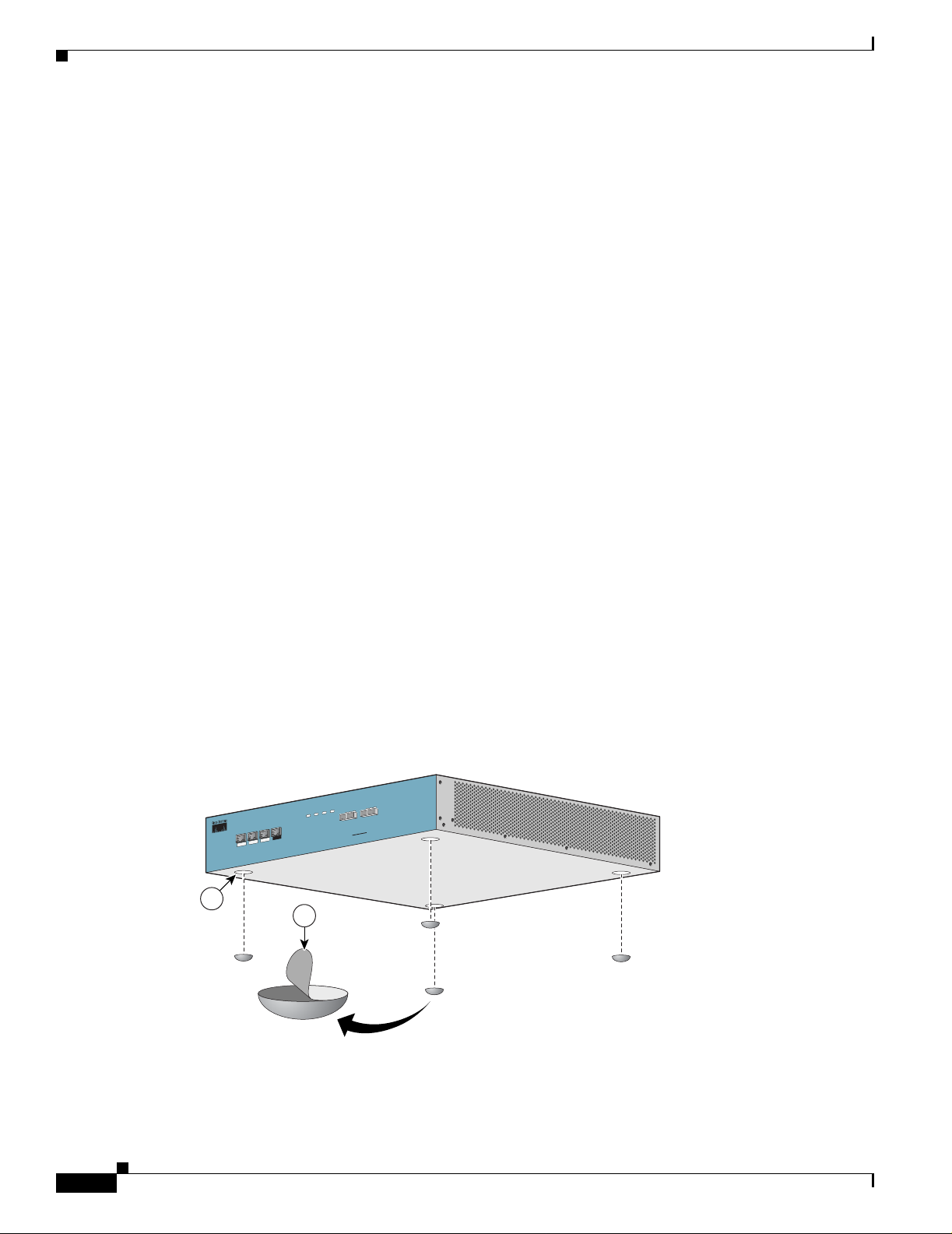
Step 1 Remove the adhesive strips from the four rubber fe et and affix the feet onto the four ma rked locati ons
on the bottom panel of the unit.
Step 2 Place the SCE 1000 pla tfo rm on t he t abl etop o r workbe nc h.
Workbench or Tabletop Installation
OL-7822-06
Cisco Service Control Engine 1000 2xGBE Quick Start Guide
1-3
Page 10

Workbench or Tabletop Ins tallation
Chapter 1 Prepare for Installation
1-4
Cisco Service Control Engine 1000 2xGBE Quick Start Guide
OL-7822-06
Page 11

Rack-Mount the SCE 1000
This section provides in forma ti on for r ack- mou nting the SCE 1000 pl at form.
• The SCE 1000 Mou nting Bra ckets
• Attach the Brackets to the SCE 1000
• Installing the C rossrai l Supp orts (Four-post ra ck on ly)
• Mount the System to the Rack
The SCE 1000 Mounting Brackets
There are two standard types of equipment racks, and the appropriate brackets for each are provided in
the enclosed kit.
• 19” rack with front rack posts — the mounting kit includes two mounting brackets as illustrated
below:
CHAPTER
2
Figure 2-1 Mounting Bracke t for 2-post Racks
210429
•
19” rack with front and back rack posts — in addition to the mounting brackets illustrated below,
the mounting kit includes two crossrail supports that the unit slides onto.
OL-7822-06
Cisco Service Control Engine 1000 2xGBE Quick Start Guide
2-1
Page 12
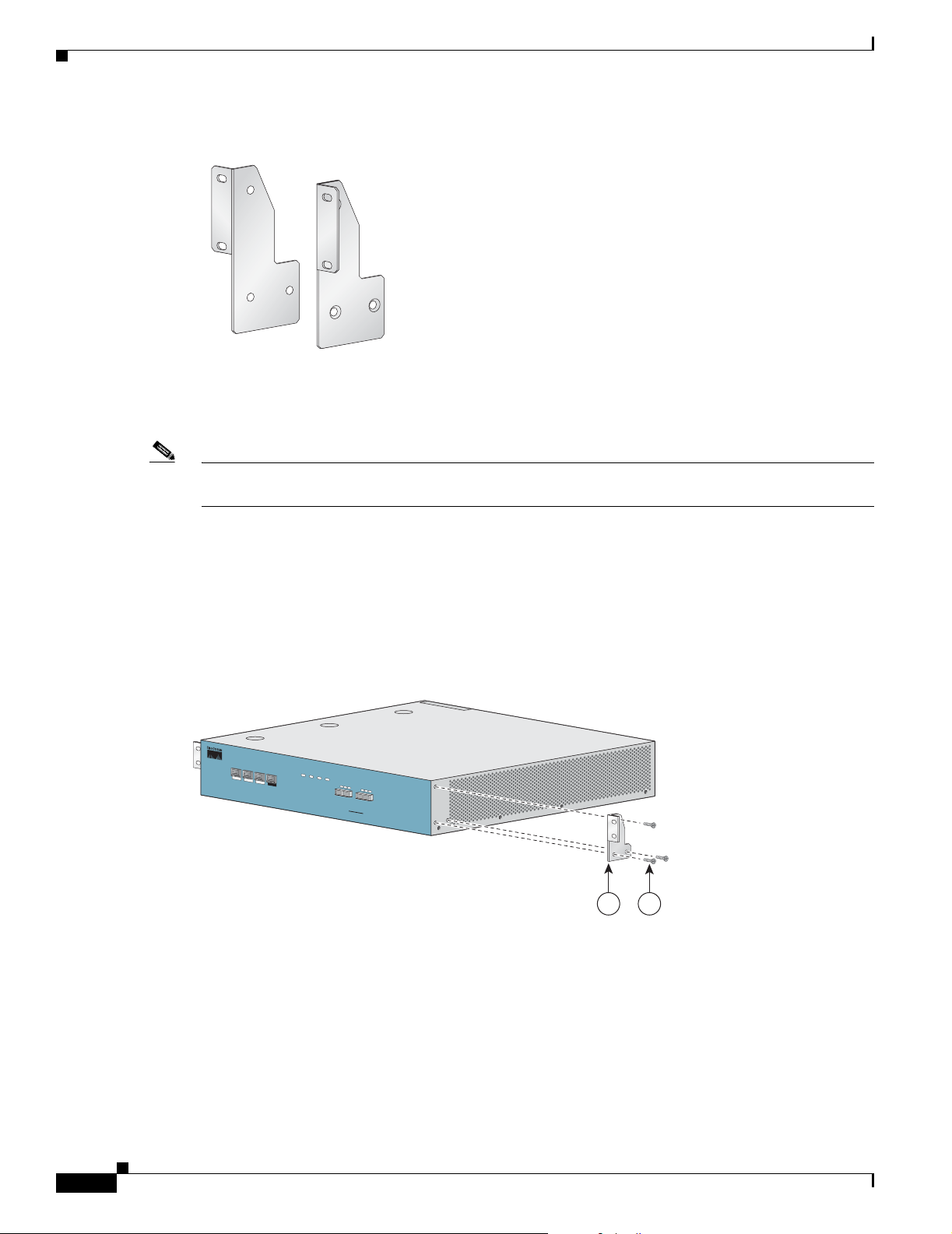
Attach the Brackets to the SCE 1000
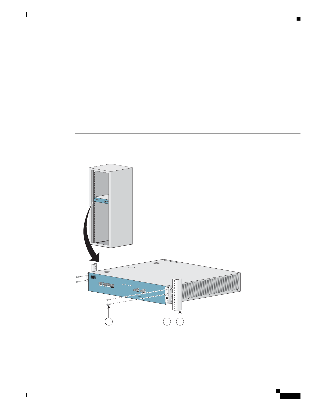
Figure 2-2 Mounting Bracke t for 4-post Racks
The SCE 1000 mounts to the two front rack posts with brackets that attach to the front of the SCE 1000
The inside width between th e two posts or mount ing strips (le ft and right ) must be at least 17.3 inch es
(44 cm).
Note Remember to leave a two-inch (5 cm) clearance on both sides of the SCE 1000 and at the rear for
adequate airflow for the inlet and exhaust vents.
Chapter2 Rack-Mount the SCE 1000
210430
Attach the Brackets to the SCE 1000
Before installing the SCE 1000 in the rack, you must first install an appropriate rack-mount bracket on
each side of the front of the SCE 1000, as illustrated in the following figures.
Figure 2-3 Attaching the Mounting Brackets (4-post)
P
W
R
A
P
W
R
B
S
T
A
T
U
S
B
Y
P
A
S
M
N
G
1
M
N
G
2
C
O
N
S
O
L
E
A
LINK
U
X
/
10/100/
AC
T
LIN
IV
E
K/
1000
10/100/
AC
T
IVE
10
00
S
L
IN
R
X
Cisco SCE 1000
K
R
X
T
X
L
IN
K
R
X
T
X
M
M
T
X
R
X
M
M
T
X
GBE-1
SUB LINE
NET
S
e
r
i
e
s
2xG
BE
210418
1 2
2-2
Cisco Service Control Engine 1000 2xGBE Quick Start Guide
OL-7822-06
Page 13
Chapter 2 Rack-Mount the SCE 10 00
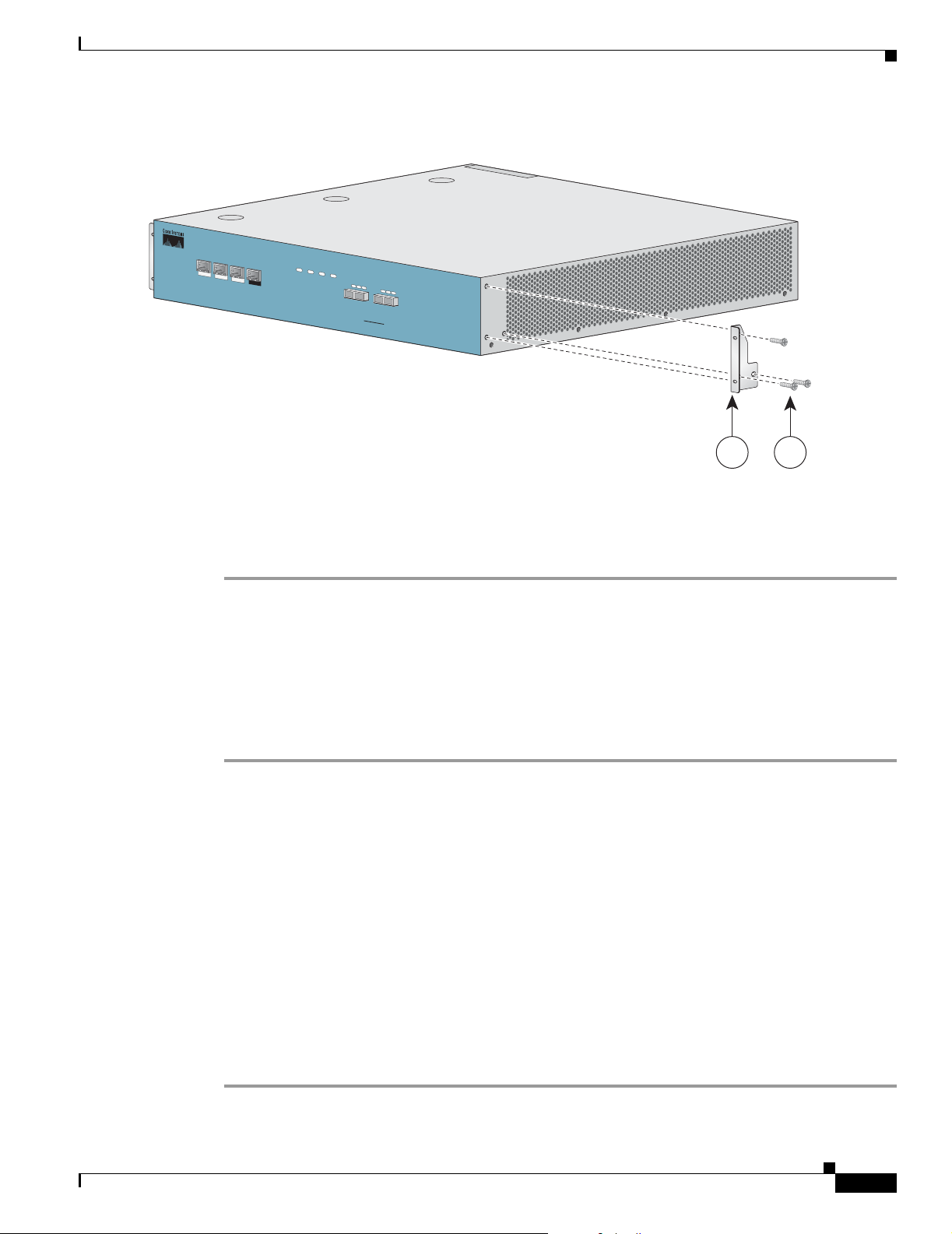
Figure 2-4 Attaching the Mounting Brackets (2-post)
M
N
G
1
M
N
G
2
C
O
N
S
O
L
E
L
IN
K
/
1
0
A
C
T
IV
E
1
A
U
/
1
0
0
0
0
0
X
/
L
IN
K
/
1
0
/
1
0
0
/
A
C
T
I
V
E
1
0
0
0
Installing the Crossrail Supports (Four-post rack only)
P
W
R
A
P
W
R
B
S
T
A
T
U
S
B
Y
P
A
S
S
L
I
N
K
R
X
T
X
R
X
M
M
T
X
GBE-1
SUB
LINE
Cisco SC
E
1000
Series
L
I
N
K
R
X
R
X
M
M
NET
2xGBE
T
X
T
X
210603
1 2
To install the rack-mount brackets on the SCE 1000 chassis, complete the following steps:
Before installing the SCE 1000 in the rack, you must first install a rack-mount bracket on each side of
the front of the SCE 1000.
Step 1 Align the rack-mount bracket to the side of the SCE 1000. Choose the proper bracket for your installation
(2-post rack or 4-post rack) as illustrated in Rack-Mount the SCE 1000
Step 2 Insert and tighten three screws.
Step 3 Repeat steps 1 and 2 on the other side of the SCE 100 0.
If mounting the SCE 100 0 in a r ack with on ly t wo pos ts, ski p to Mount the System to the Rack.
If mounting the SCE 100 0 in a rac k with fo ur po sts, p roc eed to th e next st ep, Installing the Crossrail
Supports (Four-post rack only).
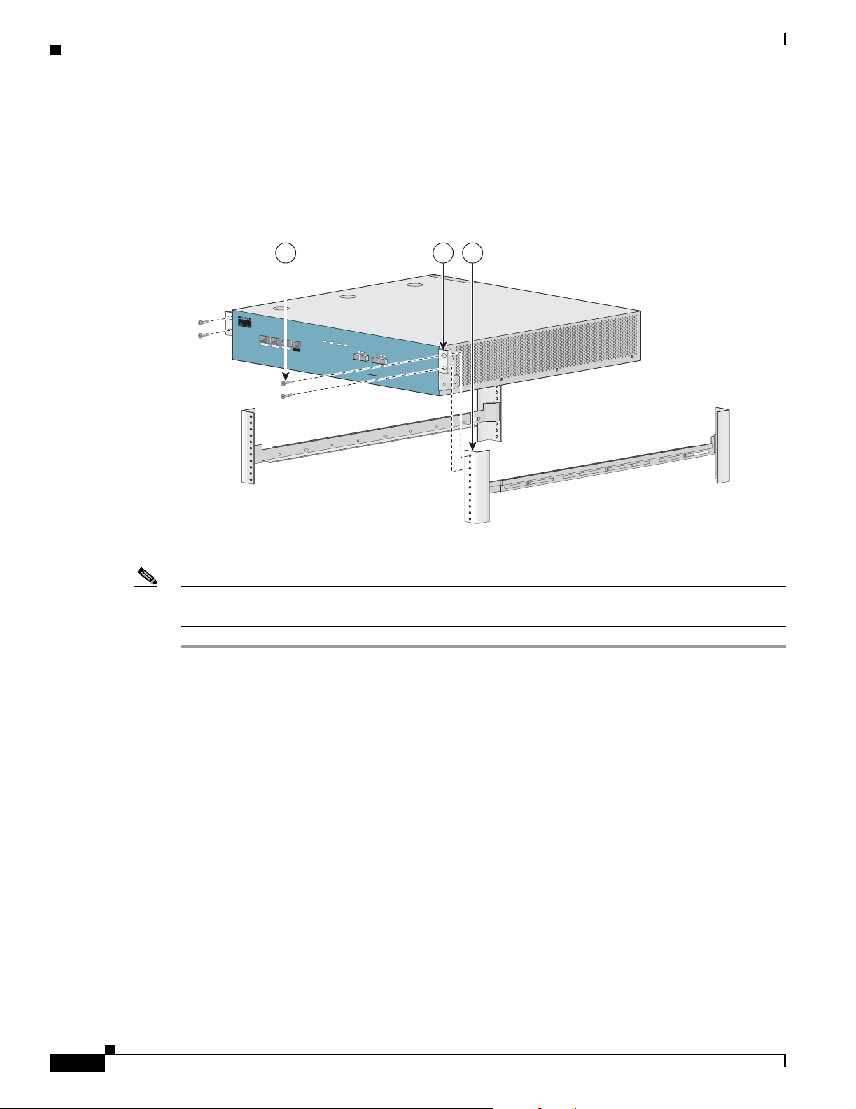
Installing the Crossrail Supports (Four-post rack only)
This section provides in for mati on for a ssembl ing the crossra il suppor t s and a ttac hing the m to the r ack.
When mounting in a rack with four posts (front and back) the two crossrail supports are mounted one on
each side of the r ack. The SC E 1000 t he n sl ide s int o the se crossr ai ls, whi ch s uppo rt th e weigh t of t he
unit.
• Assemble the Crossrail Supports
• Attach the Crossrail Supports to the Rack
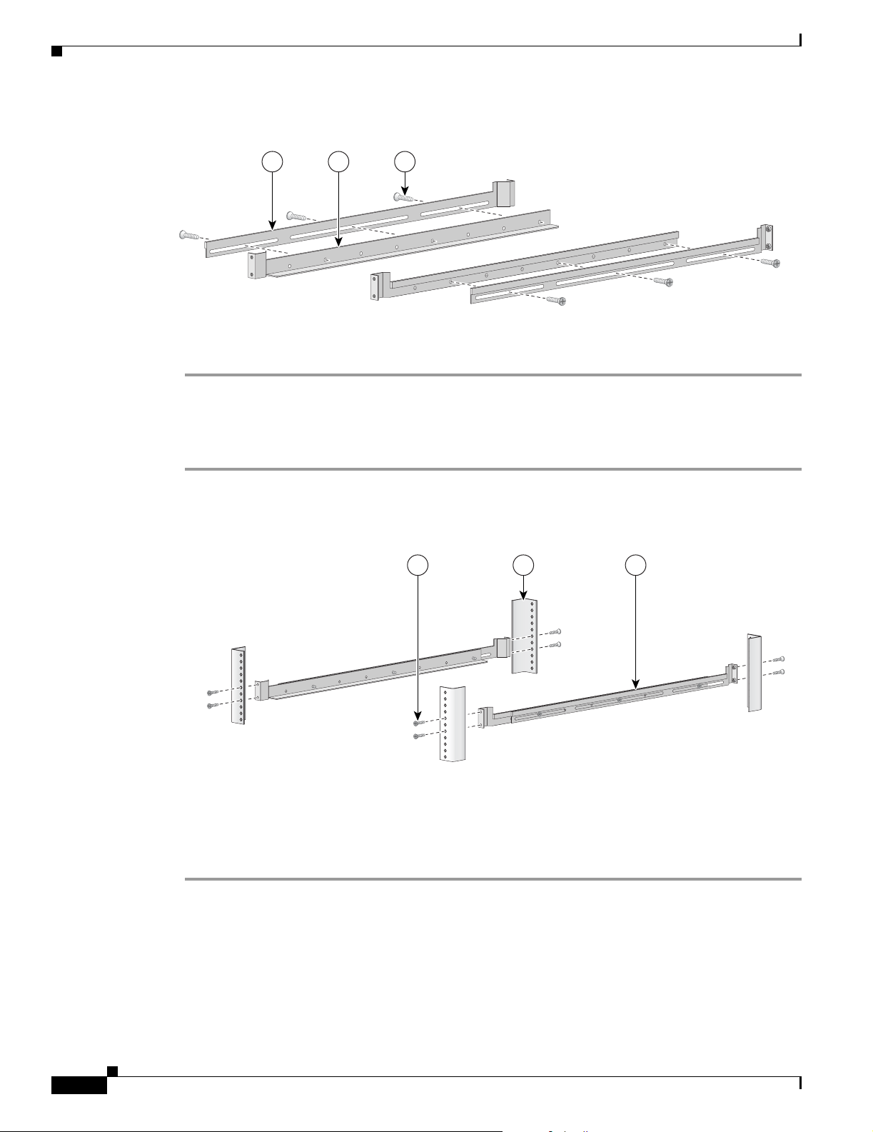
Assemble the Crossrail Supports
Step 1 Assemble the two crossrail supports. Use three screws for each crossrail assembly.
OL-7822-06
Cisco Service Control Engine 1000 2xGBE Quick Start Guide
2-3
Page 14
Mount the System to the Rack
Figure 2-5 Assembl ing the Slider Brackets
Chapter2 Rack-Mount the SCE 1000
321
92777
Step 2
Make sure that they are oriented so that both crossrails will support the SCE 1000 when they are attached
to the rack.
Attach the Crossrail Supports to the Rack
Step 1 Align the crossrail supports with the side of the rack, parallel to the floor.
Figure 2-6 Attaching the Crossrails to the Rack
321
92778
Step 2
Step 3 Insert and tighten two screws to the Back posts of the rack.
Step 4 Repeat steps 2 and 3 on the other si de of the rack , keeping th e brackets flu sh against the posts and
Insert and tighten two screws to the front posts or mo unting stri ps of the rack
parallel to the su ppo rti ng bra cket on first si de of the r ack.
Mount the System to the Rack
When the appropriate mounting brackets are securely installed, the SCE 1000 can be installed into the
rack.
Cisco Service Control Engine 1000 2xGBE Quick Start Guide
2-4
OL-7822-06
Page 15
Chapter 2 Rack-Mount the SCE 10 00
SUMMARY STEPS
1. Make sure that the rack brakes are locked or that the rack is otherwise stabilized.
2. Position the SCE 1000 so that the front end is closest to you, and lift it carefully to place it into the
3. Slide the SCE 1000 into the rack, pushing it ba ck until the bracke ts (installed at the front of the SCE
4. While keeping the br ackets f lush ag ainst the pos ts or mountin g strips , align th e holes in the b rackets
5. For each bracket, insert and tig hten two appr opriat e screws to the rack .
DETAILED STEPS
Step 1 Make sure that the rack brakes are locked or that the rack is otherwise stabilized.
Figure 2-7 Sliding the SCE Platform into the Rack
Mount the System to the Rack
rack. To prevent injury, avoid sudden twists or moves.
1000) meet the m ountin g st ri ps or posts on both si des o f the rac k.
with the holes on the rack or mounting strip.
Step 2
P
W
R
A
P
W
R
B
S
T
A
T
U
S
B
Y
P
A
S
S
M
N
G
1
C
i
s
M
c
N
o
G
2
S
C
C
E
O
N
S
2
O
0
L
E
0
0
L
I
N
A
L
S
K
I
U
N
e
K
R
X
/
X
r
1
i
0
e
/
T
1
s
X
0
0
/
A
4
C
T
L
I
I
x
V
N
E
K
G
/
1
1
0
0
0
B
/
0
1
L
0
I
0
E
N
/
A
K
C
T
R
I
X
V
E
T
1
X
0
0
0
L
I
N
K
R
X
T
X
L
I
N
K
R
X
T
X
R
X
M
M
T
X
R
X
M
M
T
X
R
X
M
M
T
X
R
X
M
M
G
B
T
E
X
-
1
S
U
B
L
I
N
E
N
E
T
G
B
E
-
2
S
U
B
L
I
N
E
/
C
A
S
C
A
D
E
N
E
T
P
W
R
A
P
W
R
B
S
T
A
T
U
S
B
Y
P
A
S
M
N
G
1
M
N
G
2
C
O
N
S
O
L
E
A
LIN
U
K
X
/
10/100/
A
C
T
LIN
IV
E
K
/
1000
10/1
00/
A
C
T
IVE
1000
S
L
IN
R
X
Cisco SC
E 1000
K
R
X
T
X
L
IN
K
R
X
T
X
M
M
T
X
R
X
M
MT
X
GBE-1
SUB
LINE
NET
S
e
r
i
e
s
2xG
BE
210419
1 2 3
Position the SCE 1000 so that the front end is clo sest to you, and lift it car efully to place it into the rack.
To prevent injury, avoid sudden twists or moves.
OL-7822-06
Step 3 Slide the SCE 1000 into the rack, pushing it back until the brackets (installed at the front of the SCE
1000) meet the m ountin g st ri ps or posts on both si des o f the rac k.
Cisco Service Control Engine 1000 2xGBE Quick Start Guide
2-5
Page 16
Mount the System to the Rack
A rack with both front and back posts will have the crossrail supports installed. Slide the SCE 1000 onto
these crossrails and push it all the way back.
Step 4 While keeping the brack ets flush against t he posts or mounting strips, al ign the holes in the brac kets with
the holes on the rack or mounting strip.
Figure 2-8 Securing the SCE Platform to the Rack
Chapter2 Rack-Mount the SCE 1000
321
P
W
R
A
P
W
R
B
S
T
A
T
U
S
B
Y
P
A
S
M
N
G
1
M
N
G
2
C
O
N
S
O
L
E
A
L
IN
U
K/
X
1
0/100/
ACTIV
LINK
E
/
1
10/10
000
0/
A
CTIV
E
1
000
S
L
R
X
Cisco SCE 1000
IN
K
R
X
T
X
L
IN
K
R
X
T
X
M
M
T
X
R
X
M
M
T
X
GBE-1
SUB LINE
NET
2xGBE
S
e
r
i
e
s
210420
Step 5
For each bracket, insert and tighten two appropriate screws to the rack.
Note Since the brackets support t h e w eigh t of the e ntire SCE 100 0 cha ssis, be sure to use al l f our sc rews to
fasten the two rack-mount brackets to the rack posts.
2-6
Cisco Service Control Engine 1000 2xGBE Quick Start Guide
OL-7822-06
Page 17
Connect the Power Supply Units
This section pr ovides infor ma ti on for g rou nding the SC E 100 0 pl atfo rm and co nne ct ing t he AC or DC
power supply units.
• Connect the C has sis G ro und, p ag e 3-1
• Connecting the Power, page 3-2
Connect the Chassis Ground
Figure 3-1 Grounding the Unit (AC)
CHAPTER
3
IN PO
BYP
ASS 1
W
ER B O
K
IN
POW
ER A O
K
210421
21
OL-7822-06
Cisco Service Control Engine 1000 2xGBE Quick Start Guide
3-1
Page 18
Connecting the Power
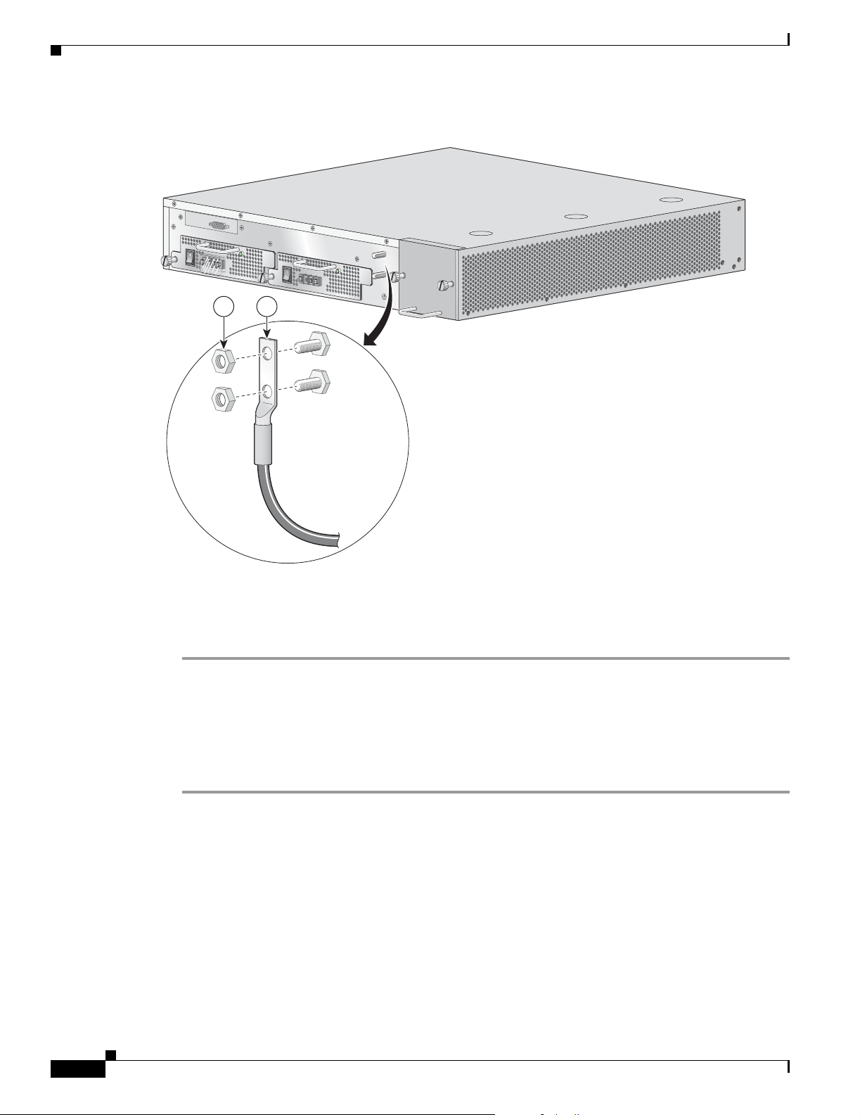
Figure 3-2 Grounding the Unit (DC)
BYP
ASS 1
IN
PO
W
ER
B
O
K
IN
PO
W
ER
A
O
K
21
Chapter 3 Connect the Power Supply Units
210422
A Grounding kit is p rovided wi th e ach SCE 10 00. Use th is Grou nding k it to p rop erl y g round th e SCE
1000 chassis.
When installing the unit, the chassis ground connection must always be made first and disconnected last.
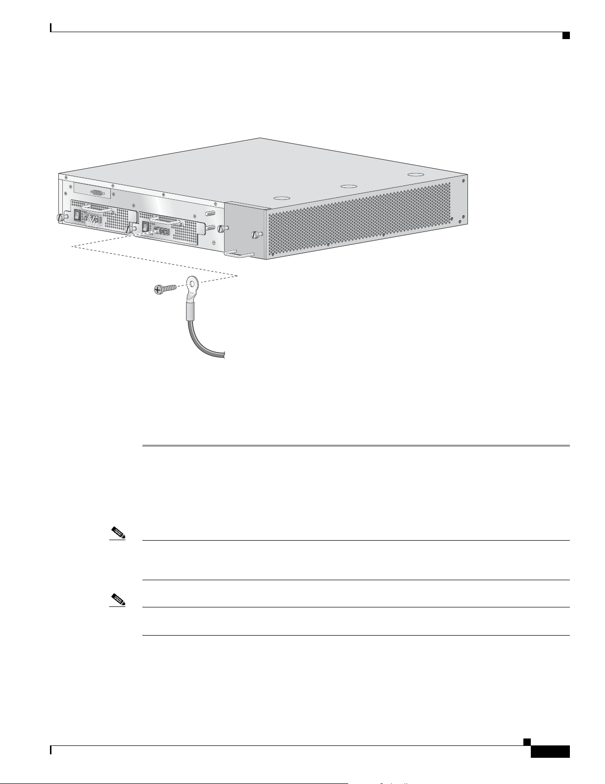
Step 1 On the rear panel of the SCE 1000, locate the chassis grounding connector (refer to the appropriate figure
for an AC- or DC-powered SCE 1000 above).
Step 2 Attach the gro und ing c ab le (gre en a nd yel low color ed cab le) , firmly fasten in g th e (enc lo sed) hex n uts
and spring was he rs with a # ¼” hex w r ench (r ef er to t he a ppr op riat e figure fo r an AC- or DC -p owered
SCE 1000 above).
The other side of the ground ing cable must be conne cted to the site equ ivalent of the AC earth.
Connecting the Power
The following sections describe how to reconnect the AC or DC power:
• Connect the DC- Input Power Sup ply Un it, p age 3-3
• Connect the AC-Input Power Supply Unit , pa ge 3-4
3-2
Cisco Service Control Engine 1000 2xGBE Quick Start Guide
OL-7822-06
Page 19
Chapter 3 Connect the Power Supply Units
Connect the DC-Input Power Supply Unit
Figure 3-3 Connecting the DC Power
BYP
ASS 1
IN POW
ER
BOK
IN
PO
W
ER
A
O
K
Connecting the Power
210424
Before completing any of the following steps, and to prevent short-circuit or shock hazards, ensure that
power is removed from the DC circuit. To ensure that all power to the power supply unit is OFF, locate
the circuit breaker on the panel board that services the DC circuit, switch the circuit breaker to the OFF
position, and tape the switch handle of the circuit breaker in the OFF position.
Wiring should be done by a professional in acco rdance w ith state an d loca l elect rical co des.
Step 1 Ensure that the DC power line input leads are disconnected from the power source.
Step 2 Using the number 2 Phillips screwdriver, remove the protective plate from the termina l block .
Step 3 Insert one receptacle screw into the hex or loop connector on one power line input, insert the screw with
the connector into the corresponding lead receptacle and tighten the receptacle screw using the number
2 Phillips. Repeat for the remaining power line input lead.
Note The color coding of the DC-input power supply leads depen ds on the col or coding of the DC power
source at your site. Make ce rtain th e lead co lor codi ng you cho ose for the D C-input power supply
matches lead color co ding used at t he DC power source .
Note Use 12 AWG (2.5 mm ) coppe r wire on ly with hex or loop con nector s. Ring termi nals must be UL
approved and suitabl e for 1 2 AWG wire.
Step 4 Using the number 2 Phillips screwdriver, securely fasten the protective plate to the termin al block.
OL-7822-06
Step 5 Connect the DC power line input leads to the DC power source through a fast 10A circuit breaker.
Step 6 Turn the on/off switch to the on position.
Cisco Service Control Engine 1000 2xGBE Quick Start Guide
3-3
Page 20
Connecting the Power
Step 7 Look at the IN an d O K LE Ds on the p ower suppl y un it an d th e co rre spo ndin g Power LE D o n th e fro nt
panel. If the D C-in put power s upply un it is op era ting p rop erly, these LEDs will be gl owing gr een.
Step 8 Ensure that the power supply is properly aligned and the installation screw is tightened.
Connect the AC-Input Power Supply Unit
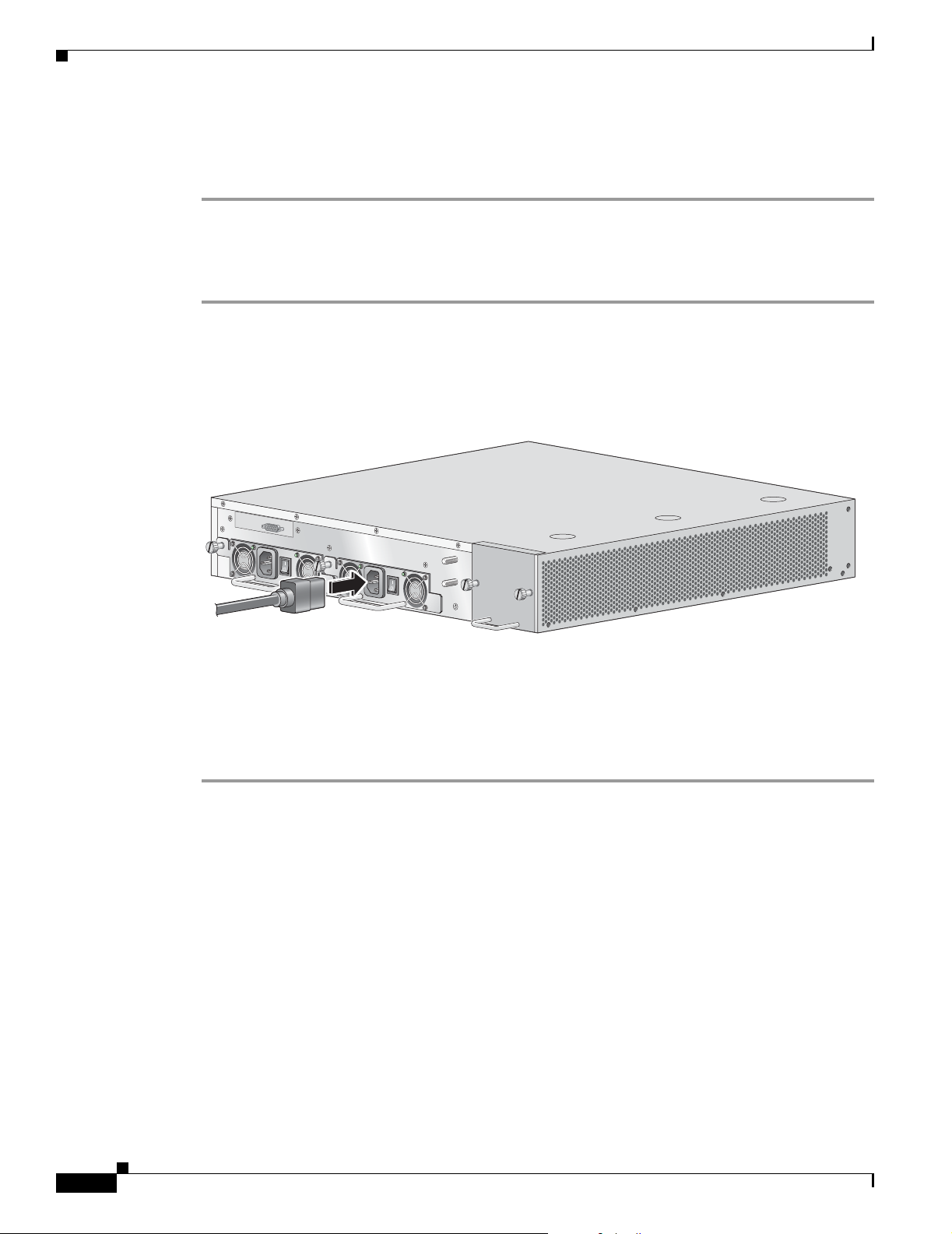
Step 1 Plug the AC-input power cable into the AC-input power receptacle on the AC-input power supply
For AC-input power, we recommend powering the SCE 2000 platform from a 120 VAC, 15A receptacle
U.S. (240 VAC, 10A internationa l) at the power source .
Figure 3-4 Connecting the AC Power
Chapter 3 Connect the Power Supply Units
BYPASS 1
IN PO
W
ER B O
Step 2
K
Plug the AC power supply cable into the AC power source.
IN
PO
W
ER A OK
Step 3 Turn the on/off switch to the on position.
Step 4 Look at the IN an d O K LE Ds on the p ower suppl y un it an d th e co rre spo ndin g Power LE D o n th e fro nt
panel. If the AC-input power supply unit is operating properly, these LEDs will be glowing green.
Step 5 Ensure that the power supply is properly aligned and the installation screw is tightened.
210423
3-4
Cisco Service Control Engine 1000 2xGBE Quick Start Guide
OL-7822-06
Page 21

Connect the Management Interfaces and Perform Initial System Configuration
This section explains how to connect the SCE 1000 platform to a local console and perform the initial
system configuration via the setup wizard that runs automatically. Additionally, this section contains
instructions for cabling the Fast Ethernet Management interface.
• Connect the Local Console, page 4-1
• Perform the Initial System Configuration, page 4-2
• Connect the Ma nage ment I nterfac e, p ag e 4-25
Connect the Local Console
Figure 4-1 Connecting to the Local Console
CHAPTER
4
OL-7822-06
P
W
R
A
P
W
R
B
S
T
A
T
U
S
B
Y
P
A
S
M
N
G
1
M
N
G
2
C
O
N
S
O
L
E
L
IN
A
C
T
21
A
K
IV
U
X
/
1
0
/1
0
0
/
L
IN
E
K
/
1
1
0
0
0
/1
0
0
0
/
A
C
T
IV
E
1
0
0
0
3
S
L
I
N
K
R
X
T
X
R
X
M
M
T
X
S
U
B
C
is
c
o
S
C
E
1
0
0
0
S
e
rie
s
2
x
G
L
I
N
K
R
X
T
X
R
X
M
M
T
G
B
E
-
1
L
I
N
E
N
E
T
B
E
X
You must first connect the unit to a local console and configure the initial settings for the SCE 1000 to
support remote management. When the initial connection is established, the setup utility will run
automatically, prompting you to perform the initial system configuration.
Make sure that the terminal configuration is as follows:
• 9600 baud
• 8 data bits
• No Parity
• 1 stop bits
• No flow control
Cisco Service Control Engine 1000 2xGBE Quick Start Guide
4-1
92965
Page 22

Perform the Initial System Configuration
The above SCE 1000 po rt p ar amet ers a re fixed and a re no t c onfigurab l e.
Step 1 Plug the <SKIP>serial cable provided with the SCE 1000 into the CON port on the front panel of the
SCE 1000.
Step 1 Connect the other end of the serial cable (with an attached DB-9 connector) to the VT100 compatible
local (serial) terminal.
Step 2 At the console. p re ss
Step 3 Enter
Step 4 several times until the Cisco logo appears on the local terminal and the setup configuration dialog is
entered.
--- System Configuration Dialog --At any point you may enter a question mark ‘?’ followed by ‘Enter’ for help.
Use ctrl-C to abort configuration dialog at any prompt.
Use ctrl-Z to jump to the end of the configuration dialog at any prompt.
Default settings are in square brackets ‘[]’.
Would you like to continue with the System Configuration Dialog? [yes/no]: y
Step 5 Type y and press pr ess Enter.
Chapter 4 Connect the Management Interfaces and Perform Initial System Co nfiguration
Enters the system c onfigura tio n d ialog .
Perform the Initial System Configuration
• Initial System Co nfigurati on , pag e 4-2
• Step 1: Configuring Initial Settings, page 4-6
• Step 2: Configuring the Hostname, page 4-7
• Step 3: Setting the Passwords, page 4-7
• Step 4: Configuring Time Settings, page 4-8
• Step 5: Configuring the DNS Settings, page 4-10
• Step 6: Configuring the RDR Formatter Destination , page 4-12
• Step 7: Configuring Access Control Lists (ACLs), page 4-12
• Step 8: Configuring SNMP, page 4-16
• Step 9: Configuring the Topology-Dependent Parameters, page 4-20
• Step 10: Completing a nd Saving the Co nfigurat ion , pag e 4-22
Initial System Configuration
• The Setup Command , pa ge 4-3
• Setup Command Parame ters , pag e 4-4
• Example, page 4-6
Cisco Service Control Engine 1000 2xGBE Quick Start Guide
4-2
OL-7822-06
Page 23

Chapter 4 Connect the Management Interfaces and Perform Ini tial System Configuration
The Setup Command
Upon initial connection to the local terminal, as described above, the system configuration wizard
automatically runs to guide the user throu gh the enti re setup process. The wizar d prompts for all
necessary parameters, displaying def ault v al ues, w here ap plica ble. You may accept the defa ult values or
define other values.
When the dialog is c om plete , you m ay r eview the new configurati on befor e a pplyi n g it. T he syste m
displays the configuration, in cludi ng paramet ers that we re not chang ed. The system also displ ays any
errors that are detected i n the configuration. When the co nfiguration is satis factory, you may apply and
save the new configuration.
The following table lists all the parameters included in the initial configuration. It is recommended that
you obtain values for any parameters that you will configure at this time before beginning the setup.
Note For further information regarding any configuration step or spe cific paramete r, refer to the relevant
section in the Cisco Service Control Engine (SCE) Software Configuration Guide .
Perform the Initial System Configuration
OL-7822-06
Cisco Service Control Engine 1000 2xGBE Quick Start Guide
4-3
Page 24

Perform the Initial System Configuration
Setup Command Parameters
Table 4-1 Setup Command Parameters
Parameter Definition
IP address IP address of the SCE 1000.
subnet mask Subnet mask of the SCE 10 00.
default gateway Default gateway.
hostname Character string used to iden tify the SCE 1000.
admin password Admin level password.
root password Root level password.
password encryption status Enable or disable password encryption?
Time Settings
time zone name and o ffset Standard time zone abbreviation and minu tes
local time and date Current local time and date. Use the format:
Chapter 4 Connect the Management Interfaces and Perform Initial System Co nfiguration
Maximum 20 characte rs.
Character string from 4- 100 char ac ter s beginni ng
with an alpha character.
Character string from 4- 100 char ac ter s beginni ng
with an alpha character.
offset from UTC.
00:00:00 1 January 2002
SNTP Configuration
broadcast client st atus Set the status of the SNT P b roadc as t c lie nt.
If enabled, the SCE wil l synchronize its local ti me
with updates received from SNTP broadcas t
servers.
unicast query interval Interval in seconds between unicast requests for
update (64 – 1024 )
unicast server IP address IP address of the SNTP unicast server.
DNS Configuration
DNS lookup status Enable or disable IP DNS-bas ed hostn ame
translati on.
default domain n am e Default domain na me to be use d for c omp leti ng
unqualified host names
IP address IP address of domain name server. ( maximum of
3 servers)
TCP port number TCP port number of the RDR-f orm atte r
destination
Access Control Lists
4-4
Cisco Service Control Engine 1000 2xGBE Quick Start Guide
OL-7822-06
Page 25

Chapter 4 Connect the Management Interfaces and Perform Ini tial System Configuration
Table 4-1 Setup Command Parameters (continued)
Parameter Definition
Access Control List number How many ACLs will be necessary? What IP
list entries (m ax imum 20 per l ist ) IP address, and wh ethe r perm itte d or deni ed
IP access ACL ID number of the ACL controlling IP access.
telnet ACL ID number of the ACL controlling telnet access.
SNMP agent status Enable or disable SNM P manage ment.
GET community names Community strings to allow GET access and
SET community name s Community strings to allow SET ac cess and
trap manager s ( maxi mu m 20) Trap manager IP address, com mun ity stri ng , a nd
Authentication Failure trap status Sets the status of the Authentication Failure traps.
enterprise traps status Sets the status of the enterprise traps.
system administrator Name of the system administrator.
Topology Configuration
connection mode Is the SCE 1000 installed using inline topology or
link bypass mode on ope ratio nal sta tus When the SCE 1000 is o per ation al, sh ould it
link bypass mode on non- oper ationa l st atus When the SCE 1000 is n ot op er ati onal , sh ould it
priority
(cascade topology only)
operational sta tus o f t he SCE a fter a bn orm al boo t After a reboot due t o a fail ur e, sh ould the SCE
Perform the Initial System Configuration
addresses will be permitted/denied access for each
management interface ? You may want ACLs for
the following :
• Any IP access
• Telnet access
• SNMP GET access
• SNMP SET access
access.
associated ACLs (max im um 2 0 ).
associated ACLs (max im um 2 0 ).
SNMP version.
receive-only topology using an optical splitter?
bypass traffic or not?
bypass traffic or cut it off?
If this is a cascaded topology, is this SCE 1000 the
primary or secondary SCE 10 00?
1000 remain in a Failure status or move to
operational status provided no othe r pr oble m was
detected?
OL-7822-06
Following are some general inst ruct ion s regar ding the se tup dia log:
• All default values appear in square brackets [defaul t] .
If no value appears in the brackets [], or more than one option appears [ yes/no ], then this parame ter
does not have a default value.
Cisco Service Control Engine 1000 2xGBE Quick Start Guide
4-5
Page 26

Perform the Initial System Configuration
• To accept the default value, press Enter .
• If you need mo re i nfo rma tio n abo ut any pa rame ter, type ? and pr ess Enter .
• T o ju mp to t he end of th e setup d ialog a t any point, ac ceptin g all re maining def ault values, press ^z .
• In certain cases, there will be two or more logically related parameters within a menu. In these
• Certain groups of re late d par amet ers, su ch a s t im e, da te , and SN T P set tin gs, fo rm sub -dia logs or
Example
Chapter 4 Connect the Management Interfaces and Perform Initial System Co nfiguration
A help message w ill ap pe ar d esc ribi ng t he expec ted f orm at of the p aram ete r and a ny ot her
requirements.
situations, it is not permitted to jump to the end of the setup dialog until all related parameters are
configured. If you t r y to jum p t o t he e nd of t he s et up dia log, the fol lowing me ssage w ill appe ar:
“Sorry, Skipping is not allowed at this stage.”
menus within the setup dialog. You may skip an entire menu, thereby accepting all default values
for the parameters within the menu.
Each group of rel ated pa rame ter s i s p refac ed by a qu esti on , ask i ng whet her yo u want t o e nte r t he
menu. To skip the menu, answer no (“n” ) to the q ues tion.
Would you like to enter the SNMP configuration menu? n
• To abort the setu p d i alog at any poi nt witho ut m aki ng any c onfigura tio n cha ng es, p re ss ^c . All
changes already entered will be lost, with the exception of time settings.
Step 1: Configuring Initial Settings
Verify the following initial settings for the SCE 1000:
• IP address
• Subnet mask
• Default gateway
All values are Internet addresses of the form ‘X.X.X.X’, where each letter corresponds to a decimal
number between 0 and 25 5.
Step 1 Configure the IP address.
The current IP ad dres s is displa yed.
• To accept the displayed value, press press Enter.
• To change the value, type the desired value in the format “x.x.x.x” and pres s pr es s Ent er.
Step 2 Configure the subnet mask.
The current sub net ma sk is displa yed.
4-6
• To accept the displayed value, press press Enter.
• To change the value, type the desired value in the format “x.x.x.x” and pres s pr es s Ent er.
Step 3 Configure the default gateway.
The current IP address of the default gateway is displayed.
• To accept the displayed value, press press Enter.
Cisco Service Control Engine 1000 2xGBE Quick Start Guide
OL-7822-06
Page 27

Chapter 4 Connect the Management Interfaces and Perform Ini tial System Configuration
• To change the value, type the desired value in the format “x.x.x.x” and pr es s pr es s Ent er.
Example
The following example disp lays a typ ica l c onfigura tio n of th e IP ad dre ss (10 .1. 5.109 ), sub net mask
(255.255.0.0), and default gateway (10.1. 1.3).
Since the IP address and the subnet mask are related, when the IP address is changed, there is no longer
a default value of the subnet mask, and it must be entered explicitly.
Enter IP address [10.1.1.201]:10.1.5.109
Enter IP subnet mask:255.255.0.0
Enter IP address of default gateway [10.1.1.3]:
Step 2: Configuring the Hostname
The hostname is used to identify the SCE 1000. It appears as part of the CLI prompt and is also returned
as the value of the MIB-II object sysName.
The maximum length is 20 characters.
Perform the Initial System Configuration
The default hostna me i s SCE 1 000 .
Step 1 Specify the hostname for the SCE platform.
The default hostname is di spla yed.
• To accept the displayed value, press press Enter.
• To change the value, type any desired character string and press press Enter.
Enter hostname [SCE 1000]:
Step 3: Setting the Passwords
Configure the passwords as follows:
• Set the password for each authorization level (User, Admin, Root).
• Enable/disabl e password en crypti on. When password encryp tion is enab led , it encr ypts the
previously entered passwords.
Note Passwords are needed for all authorization levels in order to prevent unauthorized users from accessing
the SCE 1000. Admin level should be used by the network administrator. Root level is for use by Cisco
technician.
OL-7822-06
Passwords must meet the following criteria:
• Minimum length — 4 characters
• Maximum lengt h — 10 0 ch ar act er s
• Begin with an alpha character
Cisco Service Control Engine 1000 2xGBE Quick Start Guide
4-7
Page 28

Perform the Initial System Configuration
• May contain only printable characters
Note Passwords are case sensitive.
Note The default password for all levels is “ Cisco ”.
Step 1 Configure the User password
The default User password is displayed.
• To accept the displayed value, press press Enter.
• To change the value, type the desired string and press press Enter.
Step 2 Configure the Admin password.
The default Admin password is displa yed.
• To accept the displayed value, press press Enter.
• To change the value, type the desired string and press press Enter.
Step 3 Configure the Root password.
Chapter 4 Connect the Management Interfaces and Perform Initial System Co nfiguration
The default Root password is displayed .
• To accept the displayed value, press press Enter.
• To change the value, type the desired string and press press Enter.
Step 4 Configure password encryption. By default, password enc ryption is not enabled.
• To disable password encryption, press Enter.
• To enable password enc ryp tion, type y and pr ess Enter.
EXAMPLE:
Following is an example o f ch angi ng all p as sword s. Password encr ypt ion is n ot en abl ed ( de fault).
Enter a User password [Cisco]: userin
Enter an Admin password [Cisco]: mng123
Enter a Root password [Cisco]: cistech
Enable passwords encryption? [no]:
Step 4: Configuring Time Settings
The time settings menu configures all time and date related parameters in the system. The time settings
menu includes the following:
• Time zone
4-8
• Local time
• Date
• SNTP menu
Cisco Service Control Engine 1000 2xGBE Quick Start Guide
OL-7822-06
Page 29

Chapter 4 Connect the Management Interfaces and Perform Ini tial System Configuration
You must en ter the time setting me nu to configur e SNTP settings. You may choose to skip the time
settings menu if you wish to accept all default values.
Note Unlike all other settings d efined in the s ystem c onfigura tion, se ttin g the time is done im me diat el y an d
not at the end of the setup process.
SUMMARY STEPS
1. Enter the time settings menu.
2. Configure the time zone name.
3. Specify the offset from UTC.
4. Confirm the local time and date.
5. Enter the SNTP configuration menu.
6. Configure the SNTP broadcast client. By default the SNTP broadcast client is not enabled.
7. Define the time interval between unicast upd ates .
8. Specify an IP address for the SNTP unicast server.
Perform the Initial System Configuration
DETAILED STEPS
Step 1 Enter the time settings menu.
Step 2 Configure the time zone name.
Step 3 Specify the offset from UTC.
Step 4 Confirm the local time and date.
Step 5 Enter the SNTP configuration menu.
Would you like to enter the Time settings menu? [no]: y
Type y and press press Enter.
Type the time zone abbreviation and press pr ess Enter.
Enter time zone name [UTC]: CET
Type the minutes offset from UTC and press pre ss Enter.
Enter time zone minutes offset from UTC: 60
The local time and date are displ ayed, a nd you are asked w hether you want to ch ange the m
The local time and date is 15:00:01 CET FRI 01 July 2002
Would you like to set a new time and date? [no]:
• If the time and date are correct, press
• Enter
• and go to Step 5.
• If the time and date are not correct, answer yes to the above question, and press press Enter.
Would you like to set a new time and date? [no]: y
Confirm your response and type the new time and date.
This change will take effect immediately both on the system clock and calendar;
it will also set the time zone you entered. Are you sure? [yes/no]: y
Enter new local time and date: 14:00:01 1 July 2002
Time zone was successfully set.
The system clock and the calendar were successfully set.
OL-7822-06
Cisco Service Control Engine 1000 2xGBE Quick Start Guide
4-9
Page 30

Perform the Initial System Configuration
If you do not wish to configure the SNTP, skip the rest of this section and go to .
To enter the SNTP configuration dialog, type y, and press Enter
Would you like to enter the SNTP configuration menu? [no]: y
Step 6 Configure the SNTP broadcast client. By default the SNTP broadcast client is not enabled.
• To disable the SNTP broadcast client, press press Enter.
• To enable the SNTP broadcast client, type y and press press Enter.
• Enable SNTP broadcast client? [no]:
Step 7 Define the time interval between unicast upd ates .
• To accept the displayed default value, press press En ter.
Enter time interval in seconds between unicast updates [1024]:
Step 8 Specify an IP address for the SNTP unicast server.
Type in the hostna me o r the IP ad dress in the for m x. x. x .x , and pr ess
Enter
Would you like to configure SNTP unicast servers? [no]: y
Enter IP address or hostname of SNTP unicast server: 10.1.1.1
Chapter 4 Connect the Management Interfaces and Perform Initial System Co nfiguration
EXAMPLE:
Following is a sample time setting dialog. In additio n to setting the time z one, time and da te are changed,
and SNTP unicast updates are configured.
Would you like to enter the Time settings menu? [no]: y
Enter time zone name [UTC]: ISR
Enter time zone minutes offset from UTC: 120
The local time and date is 15:35:23 ISR FRI July 19 2002
Would you like to set a new time and date? [no]: y
This change will take effect immediately both on the system clock
and the calendar; it will also set the time zone you entered.
Are you sure? [yes/no]: y
Enter new local time and date: 14:35:23 19 July 2002
Time zone was successfully set.
The system clock and the calendar were successfully set.
Would you like to enter the SNTP configuration menu? [no]: y
Enable SNTP broadcast client? [no]: y
Enter time interval in seconds between unicast updates [900]:
Would you like to configure SNTP unicast servers? [no]: y
Enter IP address or hostname of SNTP unicast server: 10.1.1.1
Step 5: Configuring the DNS Settings
The DNS configuration menu defines the IP address of the domain name server, which is used for DNS
lookup, as well as the default domain name, which is used to complete unqualified host names.
You may c ho ose t o ski p the D NS configura tio n me nu if y ou wish t o accep t a ll de fault values.
SUMMARY STEPS
Cisco Service Control Engine 1000 2xGBE Quick Start Guide
4-10
1. Enter the DNS set tings me nu.
2. Enable or disable DNS look up.
OL-7822-06
Page 31

Chapter 4 Connect the Management Interfaces and Perform Ini tial System Configuration
3. Type the default d omai n name to be us ed , an d p re ss pre ss E nte r.
4. Configure the primary domain name server .
5. Configure any additional do main nam e servers.
6. Exit the dialog.
DETAILED STEPS
Step 1 Enter the DNS set tings me nu.
Would you like to enter the DNS configuration menu? [no]: y
Type y and press pr ess E nter.
The DNS settings dialog begins.
Step 2 Enable or disable DNS look up.
• To enable DNS lo okup, pr ess press En ter.
• To disable DNS lookup, type n and press press Enter.
Enable IP DNS-based hostname translation? [yes]:
If you choose to disable DNS lookup, skip the rest of this section and go to . The rest of the dialog is not
presented, as it is ir rel evant when DNS lo okup is disa bled .
Perform the Initial System Configuration
Step 3 Type the default d omai n name to be us ed , an d p re ss pre ss E nte r.
Note that there is no default domain name.
You ma y accept th e default dom ain name or enter a new one.
Enter default domain name []:
Step 4 Configure the primary domain name server .
Type the IP addre ss of t he pr ima ry dom a in n ame server a nd p re ss pre ss Ent er.
Enter Primary DNS IP address:
Note that there is no default for this parameter.
Step 5 Configure any additional do main nam e servers.
You may configure up to three domain servers.
Would you like to add another Name Server? [no]:
• To exit the DNS settings dialog, press press Enter.
• To add another d omai n server, type y an d press pre ss Ente r.
You ar e aske d to e nter the IP add re ss o f th e next do mai n nam e se rver.
Enter Secondary DNS IP address:
Step 6 Exit the dialog.
When IP addresses for all servers have been entered, exit the dialog by pressing press Enter.
Would you like to add another Name Server? [no]:
EXAMPLE:
OL-7822-06
Following is a sample DNS configuration dial og. Th e default dom ain name is pcube. com, and t he IP
address of the D omai n N ame Se rver is 10 .1.1. 230 .
Cisco Service Control Engine 1000 2xGBE Quick Start Guide
4-11
Page 32

Chapter 4 Connect the Management Interfaces and Perform Initial System Co nfiguration
Perform the Initial System Configuration
Would you like to enter the DNS configuration menu? [no]: y
Enable IP DNS-based hostname translation? [yes]:
Enter default domain name []: pcube.com
Enter Primary DNS IP address: 10.1.1.230
Would you like to add another Name Server? [no]:
Step 6: Configuring the RDR Formatter Destination
The SCE 1000 passes Raw Data Records (RDRs) to an external collection system v ia the
RDR-Formatter. In order for the data to reach the correct location, the IP address of the external
collection system a nd its port numbe r must be configu red.
Step 1 Enter the RDR formatter configuration menu.
Would you like to enter the RDR-formatter configuration menu? [no]: y
Type y and press press Enter.
The RDR-formatter de stinatio n dialog begi ns.
Step 2 Specify the IP address of the RDR-formatter destination.
Type the IP addre ss of t he RD R-for ma tter dest inatio n a nd pr e ss pre ss Ent er.
Enter RDR-formatter destination’s IP address:
Note that there is no default for this parameter.
Step 3 Specify the TCP port number of the RDR-formatter destination.
Type the TCP port number of the RD R-form atter de stination and press pr ess Enter.
Note that there is no default for this parameter.
Enter RDR-formatter destination’s TCP port number:
EXAMPLE:
Following is a sample RDR-formatter configuration dialog, assigning the IP address and TCP port
number.
Would you like to enter the RDR-formatter configuration menu? [no]: y
Enter RDR-formatter destination’s IP address: 10.1.1.230
Enter RDR-formatter destination’s TCP port number: 33000
Step 7: Configuring Access Control Lists (ACLs)
• Information Abou t Acce ss C ontro l L ists, pag e 4-12
• Examples, page 4-15
Information About Access Control Lists
4-12
• Configuring ACLs, page 4-13
• Entry Formats, page 4-13
• Order of Entries, pa ge 4-13
Cisco Service Control Engine 1000 2xGBE Quick Start Guide
OL-7822-06
Page 33

Chapter 4 Connect the Management Interfaces and Perform Ini tial System Configuration
Configuring ACLs
The SCE 1000 can be configured with Acc ess Contro l Lists (ACLs), which are used to permit or de ny
incoming connections on any of the manage ment int erfaces.
Note ACL #0 is a pre-defined list that permits access to all IP addresses.
Configuration of access control lists is done in two stages:
1. Create the access control lists.
You may create 99 ACLs with a maximum of 20 entrie s per list. Each entry cons ists of an IP address,
and an indication of whether access is permitted or denied to this IP address.
2. Assign the ACLs to the appropriate mana gement interface. (See )
The dialog permit s yo u to sk ip the crea ti on/e dit ing of the ACLs and go dire c tly to a ssigning ACLs
to the manageme nt in terfa ces.
Entry Formats
Each ACL may permit/deny access to any IP address, one or more ranges of IP addresses, or one or more
individual IP address. Three ent ry form ats are available to suppor t these opt ions :
• Any IP address — Type the word “any”. Any IP addr ess w ill be pe rm itte d or de nie d acce ss.
Perform the Initial System Configuration
• Range of IP addresses — Type the beginning IP address in the desired range, then enter the wildcard
bits that define the range.
This wild ca rd f u nc ti on s l ike a r everse m a sk , in that all “ 1” b its in the w ild ca r d in d ica t e th e
corresponding bit in the IP address should be ignored. All other bits must match the corresponding
bit in the specified IP address. Refer to the table below for examples.
Each range of IP add re sses c an be con figured to b e pe rm itte d or de nie d ac cess.
• Individual IP address— Type the desired IP address, then enter the wildcard bits 0.0.0.0.
Each individual IP addr e ss can b e co nfigured t o be pe rmi tted or de nie d ac ce ss.
Table 4-2 IP address/Wildcard bit examples
Initial IP address Wildcard bits Range
10.1.1.0 0.0.0.255 10.1.1.0–10.1.1. 255
10.1.1.0 0.0.0.63 10.1.1.0–10.1.1.63
10.1.1.0 0.0.0.0 10.1.1.0 (individual entry)
Order of Entries
The order of the entries in the list is important. The entries in the list are tested sequentially, and the
action is determined b y the f irst entr y that matches th e connec ting IP address. There fore, when the e ntry
“any” appear s i n an Ac ce ss C ontr ol L is t, a ll su cc e ed in g e ntr ie s ar e irre l evant.
Consider two hypothetic al ACLs containing the same entries in a differe nt order.
OL-7822-06
The following list would permit access to all IP addresses, including 10.1.1.0:
permit any
deny 10.1.1. 0
Note that the above list could not actually be created using the setup utility, since after the “any” entry,
no other entries could be added to the list.
Cisco Service Control Engine 1000 2xGBE Quick Start Guide
4-13
Page 34

Perform the Initial System Configuration
The following list will deny access to IP address 10.1.1.0, but permit access to all others:
deny 10.1.1. 0
permit any
If no entry in the assigned Access Control List matches the connection, or if the Access Control List is
empty, the default action is deny.
To create the access control lists, complete the following steps:
SUMMARY STEPS
1. Enter the Access Control Lists configuration menu.
2. You have the option of cre ating or modify ing Acc ess Control Li sts, or skippi ng this sect ion and
3. Type the number of the Ac cess C ont rol Li st t o be c onfigured (1 t h rough 99) a nd pr ess Enter .
4. Begin adding entries to the selected list.
5. Type the IP address to be added to this list, and press pre ss Enter.
6. If you entered a spec ific IP addr ess, ent er t he w ild card b its t o d efine a r a nge o f I P a dd resses and
Chapter 4 Connect the Management Interfaces and Perform Initial System Co nfiguration
proceeding directly to assign the existi ng ACLs to the desired ma nageme nt interface s.
press Enter . (See Entry Formats, page 4-13.)
DETAILED STEPS
Step 1 Enter the Access Contr ol L ists c onfiguratio n m enu.
Step 2 You have the option of cre ating or modify ing Acc ess Control Li sts, or skippi ng this sect ion and
Step 3 Type the number of the Ac cess C ont rol Li st t o be c onfigured (1 t h rough 99) a nd pr ess Enter .
Step 4 Begin adding entries to the selected list.
7. The maximum number of e ntrie s in an ACL is 20.
8. When all entries are add ed to on e list, yo u are aske d whet he r you w oul d lik e to cr eate an othe r ACL.
You may d efine u p to 99 ACLs.
9. Restrict IP access to the SCE 1000 by assign ing the appr opriate ACL.
10. Restrict Telnet access to the SCE 1000 by a ssigni ng t he ap pro pria te ACL.
Would you like to enter the Access lists configuration menu? [no]:y
Type y and press press Enter.
The Access Control Lists co nfiguration dia log begins.
proceeding directly to assign the existi ng ACLs to the desired ma nageme nt interface s.
Would you like to create new Access lists or modify existing lists? [no]: y
If you choose not to create or edit Access Control Lists, skip to .
Note that there is no default for this parameter.
Indicate whether this entry is permitted access or denied access.
4-14
• To permit access press press Enter.
• To deny access type n and p ress p ress Enter.
Step 5 Type the IP address to be added to this list, and press pre ss Enter.
Note that there is no default for this parameter.
Enter IP address or the word ‘any’ to denote any IP address:
Cisco Service Control Engine 1000 2xGBE Quick Start Guide
OL-7822-06
Page 35

Chapter 4 Connect the Management Interfaces and Perform Ini tial System Configuration
Step 6 If you entered a spec ific IP addr ess, ent er the w ild card b its to d efine a ra nge of I P a dd resses a nd press
Enter . (See Entry Formats, page 4-13.)
To define an individual IP address, type 0.0.0.0 and press Enter .
There is no default fo r this para mete r.
Enter wildcard bits:
Step 7 The maximum number of e ntrie s in an ACL is 20.
If the “any” option was used, no other IP addresses may be a dded to the list.
• To add more entries, type y and press
• Enter
Would you like to add another entry to this list? [no]:y
• Enter up to 20 entries as described in ste p 5 and step 6.
• When all entries have been added, press
• Enter
Would you like to add another entry to this list? [no]:
Step 8 When all entries are added to one list, you are asked whether you would like to create another ACL. You
may define up to 99 ACLs.
Perform the Initial System Configuration
Examples
• To create another ACL, type y and press
• Enter
Would you like to configure another list? [no]: y
• Enter up to 20 IP addresses in this new ACL, as described in step 5 and step 6.
• When all ACLs have been created, press press Enter.
Would you like to configure another list? [no]:
• You ar e now prompted to assi gn the desire d ACLs to restrict IP and Telnet access.
Step 9 Restrict IP access to the SCE 1000 by assign ing the appr opriate ACL.
Type the number of the ACL to be a ssigne d to I P a ccess a nd pr ess press E nter.
To accept the default ACL, press press Enter.
Enter IP access-class [0]:
Step 10 Restrict Telnet access to the SCE 1000 by a ssigning the ap prop riat e ACL.
Type the number of the ACL to be assigned to the Telnet interface and press
To accept the default ACL, press
Enter Telnet access-class [0]: 2
Enter.
EXAMPLE 1:
This example illustrates a common access control scenario. Let us assume the following:
Enter.
OL-7822-06
• We want to permit every station to access the SCE platform on the management port (for example
ping, SNMP polling etc.) .
• We want to restrict Telnet access to only a few permitted stations.
We therefore ne ed to cr eat e two acce ss co ntro l lis ts:
• For general IP access — permit access to all IP addresses.
Cisco Service Control Engine 1000 2xGBE Quick Start Guide
4-15
Page 36

Perform the Initial System Configuration
• For Te lnet — permit access to the specified IP address, and deny to all others.
ACL #1 = permit any IP address. Assign to IP access.
ACL #2 = permit access to 10.1.1.0, 10.10.10. 1, deny to all other s. Assign t o Telnet access.
Would you like to enter the Access lists configuration menu? [no]: y
Would you like to create new Access lists or modify existing lists? [no]: y
Enter ACL number: 1
Does this entry permit access? [yes]:
Enter IP address or the word ‘any’ to denote any IP address: any
This entry matches every IP address, no use in adding more entries to this list.
Would you like to configure another list? [no]: y
Enter ACL number: 2
Does this entry permit access? [yes]:
Enter IP address or the word ‘any’ to denote any IP address: 10.1.1.0
Enter wildcard bits: 0.0.0.0
Would you like to add another entry to this list? [no]:y
Does this entry permit access? [yes]:
Enter IP address or the word ‘any’ to denote any IP address: 10.10.10.1
Enter wildcard bits: 0.0.0.0
Would you like to add another entry to this list? [no]:y
Does this entry permit access? [yes]:n
Enter IP address or the word ‘any’ to denote any IP address: any
This entry matches every IP address, no use in adding more entries to this list.
Would you like to configure another list? [no]:
Enter IP access-class [0]: 1
Enter Telnet access-class [0]: 2
Chapter 4 Connect the Management Interfaces and Perform Initial System Co nfiguration
EXAMPLE 2:
This example skips t he first se ction of the d ial og (c r eat ing/mo di fyin g), and pr ocee ds dire ct ly to as sig n
existing ACLs.
Would you like to enter the Access lists configuration menu? [no]: y
Would you like to create new Access lists or modify existing lists? [no]:
Enter IP access-class [0]: 10
Enter Telnet access-class [0]: 22
Step 8: Configuring SNMP
Managing the SCE 1000 is possible al so via a Network Ma nagement System (NMS) t hat suppor ts
SNMP. By defaul t, SN MP is d isab led on the SCE 1 000 .
To enable SNMP management you must configure the following basic SNMP parameters:
• SNMP traps status and managers.
• Community strings (where an SNMP community string is a text string that acts like a password to
permit access to the SNMP agen t on the SCE 100 0).
SUMMARY STEPS
1. Enter the SNMP configuration menu.
2. Enable SNMP manageme nt.
3. Configure the SNMP GET community.
4-16
4. Type the SNMP GET com mun ity na me an d p ress p ress E nte r.
5. Assign an access list to restr ict the SNMP ma nage ment sta tions t hat ma y use this G ET co mm unity.
6. Configure additional GET communities.
Cisco Service Control Engine 1000 2xGBE Quick Start Guide
OL-7822-06
Page 37

Chapter 4 Connect the Management Interfaces and Perform Ini tial System Configuration
7. To add more entries, do not accept the default::
8. Enter up to 20 SN MP GET com mun itie s as de scri bed in step 3 .
9. When all entries have been added, accept the default:
10. Configure the SNMP SET community.
11. Type the SNMP SET community name an d press press Ente r.
12. Assign an access list to restrict the SNMP management stations that may use this SET community.
13. Configure additional SET communities.
14. To add more entries, do not accept the default::
15. Enter up to 20 SN MP SET c om muni ties as descr ibe d in ste p 5 .
16. When all entries have been added, accept the default:
17. Configure the SNMP trap managers.
18. Enter the SNMP tra p ma na gers menu .
19. Configure the trap manager IP address
20. Configure the trap manager community string
Perform the Initial System Configuration
DETAILED STEPS
Step 1 Enter the SNMP configuration menu.
Step 2 Enable SNMP manageme nt.
21. Configure the trap manager SNMP version.
22. Configure additional trap managers.
23. To add more entries do not accept the default:
24. Enter up to 20 trap managers as descr ibed in step 7.
25. When all entries have been added, accept the default:
26. Configure the Authentication Failure trap status.
27. Configure the SCE enterprise trap status.
28. Specify the system administrator.
Would you like to enter the SNMP configuration menu? [no]: y
Type y and press press Enter.
The SNMP configuration dial og begins.
y and press press Enter.
Type
Enable SNMP management? [no]: y
If you choose to disable SNMP management, skip the rest of this section and go to . The rest of the dialog
is not presente d, a s it is i rrelevant when SNMP ma nage me nt is di sabl ed .
OL-7822-06
Step 3 Configure the SNMP GET community.
a. Type the SNMP GET community name an d p ress p ress E nte r.
The SNMP agent that resides in side the SCE 1000 will respond onl y to GET requ ests that use th is
community string.
Enter SNMP GET community name:
Note that there is no default for this parameter.
Cisco Service Control Engine 1000 2xGBE Quick Start Guide
4-17
Page 38

Perform the Initial System Configuration
b. Assign an access list to r estr ict the SNMP ma nage ment sta tions t hat ma y use t his G ET co mm unity.
T ype a number (1 through 99) or type “0” to permit access to all IP addresses, and press press Enter.
Enter Access list number allowing access with this community string, use ‘0’ to allow
all:
Step 4 Configure additional GET communities.
The maximum number of G ET commu nities is 20.
a. To add more entries, do not accept the default::
Would you like to add another SNMP GET community? [no]:
Type y and press press Ent er.
b. Enter up to 20 SN MP GET com mun ities a s descr ibed in step 3 .
c. When all entries have been added, accept the default:
Would you like to add another SNMP GET community? [no]:
Press Enter to accept.
Step 5 Configure the SNMP SET community.
a. Type the SNMP SET community name and press press Enter.
Chapter 4 Connect the Management Interfaces and Perform Initial System Co nfiguration
The SNMP agent that reside s inside the SCE 1000 will respo nd only to SET req uests that use this
community string.
Enter SNMP SET community name:
Note that there is no default for this parameter.
b. Assign an access list to restrict the SNMP management stations that may use this SET community.
T ype a number (1 through 99) or type “0” to permit access to all IP addresses, and press press Enter.
Enter Access list number allowing access with this community string, use ‘0’ to allow
all:
Step 6 Configure additional SET communities.
a. To add more entries, do not accept the default::
Would you like to add another SNMP SET community? [no]:
Type y and press press Ent er.
b. Enter up to 20 SN MP SET c ommu ni ties as descr ibe d in ste p 5 .
c. When all entries have been added, accept the default:
Would you like to add another SNMP SET community? [no]:
Press Enter to accept.
Step 7 Configure the SNMP trap managers.
a. Enter the SNM P tra p ma nage rs menu .
Would you like to configure SNMP trap managers? [no]: y
Type y and press pr ess E nter.
The SNMP trap m a nager s d i alog begins.
4-18
If you choose not to configure SNMP trap managers, the dialog skips to the authentication failure
trap status. (See step 9.)
b. Configure the trap manager IP address
Enter SNMP trap manager IP address:
Type the trap manager community string and press press Enter.
Cisco Service Control Engine 1000 2xGBE Quick Start Guide
OL-7822-06
Page 39

Chapter 4 Connect the Management Interfaces and Perform Ini tial System Configuration
Note that there is no default for this parameter.
c. Configure the trap manager community string
Enter SNMP trap manager community string:
Type the trap manager community string and press press Enter.
Note that there is no default for this parameter.
d. Configure the trap manager SNMP version.
Enter trap manager SNMP version:
Type the number of the trap manage r SNMP version (1 or 2c) and press press En ter.
Note that there is no default for this parameter.
Step 8 Configure additional trap managers.
The maximum number of tra p manage rs is 20.
a. To add more entries do not accept the default:
Would you like to add another SNMP trap manager? [no]:
Type y and press press Ent er.
b. Enter up to 20 trap manage rs as descri bed in step 7.
Perform the Initial System Configuration
Step 9 Configure the Authentication Failure trap status.
Step 10 Configure the SCE enterprise trap status.
Step 11 Specify the system administrator.
EXAMPLE:
c. When all entries have been added, accept the default:
Would you like to add another SNMP trap manager? [no]:
Press Enter to accept.
• To disable the Authentication Failure trap, press press Enter.
• To enable the Authentication Failure trap, type y and press press Enter.
Enable the ‘Authentication Failure’ trap [no]:
• To disable the SCE enterprise traps, type n press press Ent er.
• To enable the SCE enterprise traps, type y and press press Enter.
Enable the SCE enterprise traps []:
Type the name of the system admi nistrat or and press pre ss Enter.
Note that there is no default for this parameter.
Enter system administrator contact name []:
Following is a sample SNM P c on figurat ion, configu ring one tr ap man ag er, one GET com mu nit y, and
one SET community, and enabling the authentication failure trap, as well as all enterprise traps.
Would you like to enter the SNMP configuration menu? [no]: y
Enable SNMP management? [no]: y
Enter SNMP GET community name[]: public
Enter Access list number allowing access with this community string, use ‘0’ to allow all:
0
Would you like to add another SNMP GET community? [no]:
Enter SNMP SET community name[]: private
Enter Access list number allowing access with this community string, use ‘0’ to allow all:
2
OL-7822-06
Cisco Service Control Engine 1000 2xGBE Quick Start Guide
4-19
Page 40

Chapter 4 Connect the Management Interfaces and Perform Initial System Co nfiguration
Perform the Initial System Configuration
Would you like to add another SNMP SET community? [no]:
Would you like to configure SNMP trap managers? [no]: y
Enter SNMP trap manager IP address: 10.1.1.253
Enter SNMP trap manager community string: public
Enter trap manager SNMP version: 2c
Would you like to add another SNMP trap manager? [no]:
Enable the ‘Authentication Failure’ trap [no]: y
Enable SCE enterprise traps []: y
Enter system administrator contact name []: John Smith
Step 9: Configuring the Topology-Dependent Parameters
• About the Topology-Dependent Parameter s, page 4-20
• Examples, page 4-21
About the Topology-Dependent Parameters
The topology configuration me nu is a se rie s of g uid ed que sti ons rel at ing to the deploym en t of the SCE
1000 in the network and its mod e of operat ion. Values for the parameters are configured based on the
user answers.
The correct value for each parameter must be ascertained before configuring the system to make sure
that the system will function in the desired manner.
There are th ree top ol ogy- rel ate d para met er s:
• Connection mode — Can be either I nlin e or R eceive-only, depending on the physic al inst all ation
of the SCE 1000.
• Bypass state when the SCE 1000 is not operational (on-failure) — This parameter determines
whether the system cuts the traffic or bypasses it when the SCE 1000 has failed.
• Status after reboot caused by fatal error or abnormal shutdown — This parameter determines
whether the SCE 1000 returns to normal operational state after a failure.
• The procedure desc ribe d bel ow is a hypo theti cal prese nt ation o f al l t he q ue stio ns in t he t o pology
configuration. In actual practice, it is impossible for all questions to be presented in any one
configuration, as this part of the dialog is not linear like the other sections, but branches depe nding
on the parameter values entered.
Study the examples th at fol low to un de rsta nd th e proc ed ure f or various t opol ogie s.
Step 1 Enter the topology c onfigurati on m enu.
Would you like to enter the Topology configuration menu? [no]: y
• Enter your password i f pr om pted .
Type
y and press press Enter.
The topology configuration di alog b egins.
4-20
Step 2 Specify the co nnec tion mode .
• To define inline connection mod e, p ress p re ss Ente r.
• To define receive-only connection mode, type 2 and press press Enter.
Enter Connection mode:
1- inline
2- receive-only
Enter your choice [1]:
Cisco Service Control Engine 1000 2xGBE Quick Start Guide
OL-7822-06
Page 41

Chapter 4 Connect the Management Interfaces and Perform Ini tial System Configuration
Step 3 Specify the On-failure link be havior.
• To specify Bypass , press pre ss Enter.
• To specify Cuto ff , type 2 and press pr ess Enter.
Enter On-failure behavior:
1- bypass
2- cutoff
Enter your choice [1]:
Step 4 Specify the admin status of the SCE 1000 afte r abnorma l boot.
• To specify Not-Operational status after abnor mal boot , pr ess pr ess Ent er.
• To specify Operational status after abnormal b oot, t yp e 1 and pr es s pres s E nt er.
Enter admin status of the SCe after abnormal boot:
1- Operational
2- Not-Operational
Enter your choice [1]:
Examples
Perform the Initial System Configuration
The following exampl es pre sen t the p roce dur e for c on figurin g t he top ol ogy-re l ated pa ra met ers f or
various topologies. Refer the for a summary of appropriate values for the parameters for each topology.
• EXAMPLE 1:, page 4-21
• EXAMPLE 2:, page 4-21
• EXAMPLE 3:, page 4-22
EXAMPLE 1:
Following is a sample topology configuration for a t opology using a n external swit ch.
All other parameter values are automatically assigned by the system as follows:
• Link bypass mode on-fai lure — Bypass
• Admin status of the SCE after abnormal boot — Operational
Would you like to enter the Topology configuration menu? [no]: y
Enter Connection mode:
1- inline
2- receive-only
Enter your choice [1]: 2
EXAMPLE 2:
Following is a sample topology configuration for a non-r edund ant bump-in- the-w ire (inline ) topolo gy.
All values are the system default values, so it is not necessary to type in the response. Simply press enter
at each line.
• Connection mode — Inline
• For a non-redundant topo logy, link bypass on-failure shou ld be Bypa ss, so tha t tra ffic continues to
flow through the link.
OL-7822-06
• After operation of the system resumes, and the SCE 1000 reboots, the SCE 1000 will resume
operation. (Admi n st atu s a fte r ab norma l re bo ot i s Oper at ion al. )
Would you like to enter the Topology configuration menu? [no]: y
Enter Connection mode:
1- inline
Cisco Service Control Engine 1000 2xGBE Quick Start Guide
4-21
Page 42

Perform the Initial System Configuration
2- receive-only
Enter your choice [1]:
Enter On-failure behavior:
1- Bypass
2- Cutoff
Enter your choice [1]:
Enter admin status of the SCe after abnormal boot:
1- Operational
2- Not-Operational
Enter your choice [1]:
Data collection for the system configuration is completed.
EXAMPLE 3:
Following is a sample topology configuration for a re dunda nt inline t opology.
• Connection mode — Inline
• For a redundant topology, link bypass on-failure should be Cutoff, so that operation switc hes to the
backup link.
• After operation of the system resumes, and the SCE 1000 reboots, the SCE 1000 will resume
operation. (Admi n st atu s a fte r ab norma l re bo ot i s Oper at ion al. )
Would you like to enter the Topology configuration menu? [no]: y
Enter Connection mode:
1- inline
2- receive-only
Enter your choice [1]: 2
Enter On-failure behavior:
1- Bypass
2- Cutoff
Enter your choice [1]:2
Enter admin status of the SCE after abnormal boot:
1- Operational
2- Not-Operational
Enter your choice [1]:
Data collection for the system configuration is completed.
Chapter 4 Connect the Management Interfaces and Perform Initial System Co nfiguration
Step 10: Completing and Saving the Configuration
When you have completed the entire configuration, the system checks for errors. If errors are found, a
warning message app ears. W hen t h e co nfigur ation is err or-free, y ou ma y ap ply an d save it.
To complete and save the configuration, complete the following steps:
SUMMARY STEPS
1. Review the new configuration.
2. View errors (if any).
3. Apply and save the configuration.
4. Confirm saving and applying the configuration.
5. Save the configuration to a remote location.
6. This completes the pro cedur es for i nitial con figurat ion o f the SCE 1 000 pl at form.
Cisco Service Control Engine 1000 2xGBE Quick Start Guide
4-22
OL-7822-06
Page 43

Chapter 4 Connect the Management Interfaces and Perform Ini tial System Configuration
DETAILED STEPS
Step 1 Review the new configuration.
The system informs you that data collection is complete.
We recommend that you view the entire new configuration before it is applied.
Type
y and press press Enter.
Note that there is no default.
If there are no errors, go to step 3.
Data collection for the system configuration is completed.
Would you like to view the new configuration before it is applied? [yes/no]: y
Step 2 View errors (if any).
If any errors are detected, you may choose to view them.
Press press Enter.
Found errors in the new configuration, would you like to view them? [yes]:
The following errors were found:
Warning - RDR formatter destination 10.1.1.1 is not allowed in the IP access-class.
Step 3 Apply and save the configuration.
Perform the Initial System Configuration
You ar e aske d w het her to app ly a nd save the co nfigurati on.
Apply and Save this configuration? [yes/no]:
• To apply and save the co nfigurat ion, ty pe y and press press Enter.
Setup procedure aborted, no configuration changes made.
• If the setup is aborted, the dialog is ended.
Step 4 Confirm saving and applying the configuration.
If there are no errors, the system r eq u est s confirmation of either a yes or no an s we r, to prevent mistakes .
Type the appropriat e answer (y or n) and pre ss press Ente r.
The running configuration would be overwritten by the changes you have just entered, are
you sure? [yes/no]:
The selected action is carried out by the system.
The selected action is carried out by the system.
• If the apply and save action is not confirmed ( no ), the setup is aborted.
Setup procedure aborted, no configuration changes made.
• If the apply and save action is confirmed ( yes ), the configura tion is ap plied and saved.
The new running configuration will be saved to the startup configuration.
Step 5 Save the configuration to a remote location.
If the configuration was applied and saved, you may also save a backup copy to a file at a remote station.
Do you want to save a copy of the startup configuration file in a remote station? [no]:
To save the configuration to a remote station, type y and press press Enter.
The system will ask for FTP path:
Enter a full FTP path of the remote destination:
Step 6 This completes the pro cedur es for i nitial con figurat ion o f the SCE 1 000 pl at form.
The system informs you that the configur ation is com plete .
Committing configuration...
Configuration completed successfully.
Saving configuration...
Writing general configuration file to temporary location...
OL-7822-06
Cisco Service Control Engine 1000 2xGBE Quick Start Guide
4-23
Page 44

Perform the Initial System Configuration
Backing-up general configuration file...
Copy temporary file to final location...
Done!
Examples
• EXAMPLE 1:, page 4-24
• EXAMPLE 2:, page 4-24
• EXAMPLE 3:, page 4-24
EXAMPLE 1:
Following is an example of a configuration that the user aborted due to errors detected in the
configuration.
Note that no confirmation is requested for the decision to abort the setup. Had there been no errors,
confirmation would have been requested befor e aborting .
Data collection for the system configuration is completed.
Would you like to view the new configuration before it is applied? [yes/no]: n
Found errors in the new configuration, would you like to view them? [yes]: y
The following errors were found:
Warning - RDR formatter destination 10.1.1.1 is not allowed in the IP access-class.
Warning - default Gateway 10.1.1.1 is not allowed in the IP access-class.
Warning - IP Access list (1) conflicts with Telnet Access list (2) as follows:
Access list 2 permits all addresses while Access list 1 denies it.
Apply and Save this configuration? [yes/no]: n
Setup procedure aborted, no configuration changes made.
Chapter 4 Connect the Management Interfaces and Perform Initial System Co nfiguration
EXAMPLE 2:
Following is an example of a configuration tha t was applied an d saved to the startup co nfiguration a s
well as to an FTP site.
Although not d emonst r ate d in th is examp le, it is re co mmen de d tha t you always view th e c onfigura tio n
before applying i t.
Data collection for the system configuration is completed.
Would you like to view the new configuration before it is applied? [yes/no]:
Apply and Save this configuration? [yes/no]: y
(New configuration would be displayed here)
The running configuration would be overwritten by the changes you have just entered, are
you sure? [yes/no]:y
The new running configuration will be saved to the startup configuration.
Do you want to save a copy of the startup configuration file in a remote station? [no]:y
Enter a full FTP path of the remote destination:
ftp://vk:vk@10.1.1.253/h:/copyofstartup.txt
Committing configuration...
Configuration completed successfully.
Saving configuration...
Writing general configuration file to temporary location...
Backing-up general configuration file...
Copy temporary file to final location...
Done!
EXAMPLE 3:
Following is an example of a configuration tha t was aborted , altho ugh no errors w ere detec ted.
4-24
Cisco Service Control Engine 1000 2xGBE Quick Start Guide
OL-7822-06
Page 45

Chapter 4 Connect the Management Interfaces and Perform Ini tial System Configuration
Data collection for the system configuration is completed.
Would you like to view the new configuration before it is applied? [yes/no]:
Apply and Save this configuration? [yes/no]: n
The changes you have just entered would be discarded, are you sure? [yes/no]:y
Setup procedure aborted, no configuration changes made.
Connect the Management Interface
Figure 4-2 Cabling the Management Port
P
W
R
A
P
W
R
B
S
T
AT
U
S
B
Y
P
A
S
M
N
G
1
M
N
G
2
C
O
N
S
O
L
E
L
IN
A
C
T
21
A
K
IV
U
/
E
X
10
/10
0
/
L
IN
K
/
10
10
00
/1
0
0
/
A
C
T
IV
E
1
0
0
0
3
S
L
I
N
K
R
X
T
X
L
I
N
K
R
X
T
X
L
I
N
R
X
M
M
S
U
B
K
T
X
R
X
M
M
T
X
R
XM
G
B
E
-
1
L
I
N
E
N
E
T
S
U
Connect the Management Interface
C
is
co
S
C
E
2
0
0
0
Series
4
xG
B
E
R
X
T
X
L
I
N
K
R
X
T
X
M
T
X
R
X
M
M
T
X
G
B
E
-
2
B
L
I
N
E
/
C
A
S
C
A
D
E
N
E
T
92791
Note By default, the management port is configured to auto-negotiation enabled.
Step 1 Plug the Ethernet cable provided (with attached RJ-45 connector) into the Mng 1 port on the front panel
Step 2 Connect the other end of t he Ethern et cable in to your managem ent network .
Step 3 Test connectivity. From the host t hat you inte nd to use for re mote ma nageme nt, ping to th e SCE 1000
EXAMPLE:
The SCE 1000 ha s two ma nage me nt ports , labe led M ng 1 an d M ng 2. U se the Mn g 1 po rt.
of the SCE 1000.
The Link LED on t he SCE 1 000 mana gem en t por t sh ould lig ht u p.
by typing ping and the SCE 1000 IP address, and pre ssing Ent er (see th e example, bel ow).
This verifies that an active connection exists between the specified station and the management port.
The following example d ispl ays a typ ic al ping r esponse wher e the ta rget IP ad dre ss is 10 .1.1 .201 .
C:\>ping 10.1.1.201
pinging 10.1.1.201 ...
PING 10.1.1.201: 56 data bytes
64 bytes from host (10.1.1.201): icmp_seq=0. time=0. ms
64 bytes from host (10.1.1.201): icmp_seq=1. time=0. ms
64 bytes from host (10.1.1.201): icmp_seq=2. time=0. ms
64 bytes from host (10.1.1.201): icmp_seq=3. time=0. ms
----10.1.1.201 PING Statistics---4 packets transmitted, 4 packets received, 0% packet loss
round-trip (ms) min/avg/max = 0/0/0
OL-7822-06
Cisco Service Control Engine 1000 2xGBE Quick Start Guide
4-25
Page 46

Connect the Management In terface
Chapter 4 Connect the Management Interfaces and Perform Initial System Co nfiguration
4-26
Cisco Service Control Engine 1000 2xGBE Quick Start Guide
OL-7822-06
Page 47

Cable the Line Ports
This module provid es inst ru ctions fo r ca bling t he G igab i t Eth er ne t por ts a nd fo r configuri ng G iga bit
Ethernet (GBE) int erface para meter s.
Note When installing an External Optical Bypass module, the SCE 1000 line ports are connected to the
module. See Appendix A in the Cisco SCE 1000 2xGBE Installation and Configuration Guid e for
complete instructions.
• Information A bout Cabl ing, p age 5-1
• Cabling the Line Interfaces, page 5-3
Information About Cabling
CHAPTER
5
• Single Link: Inline Topology, page 5-1
• Single Link: Receive-only Topology, page 5-2
Single Link: Inline Topology
In the inline or bump-in-the-wire topolo gy, illustrated in the diagram bellow, the SCE 1000 resides
physically on the data link between the subscriber side, usually either a BRAS (in DSL access), a PDSN
(in wireless access), a CMTS (in the Cable access), or a switch or router aggregator (in other topologies),
and the network side, usually a router or layer 3 switch network element. This is the inline topology,
providing both traffic monitoring and control capabilities.
In this topology, all the traffic of the SCE 100 0 is de ployed a s a tr an spare nt l aye r2 overlay on the
customer’s existing network.
OL-7822-06
Cisco Service Control Engine 1000 2xGBE Quick Start Guide
5-1
Page 48

Information About Cabling
Figure 5-1 Bump-in-the-Wire Installation
Chapter5 Cable the Line Ports
STATUS
PWR A
PWR B
BYPASS
LINK
RX
Subscriber
Single Link: Receive-only Topology
RX
TX
TX
MM
SUB LINE
GBE-1
LINKRXTX
RX MM
NET
Cisco SCE 1000
Series
2xGBE
TX
NetworkSubscriber
Network
Router/SwitchRouter/Switch
92964
In this topology, an external optical sp litt er re sides phys ic ally on the GB E link betw een the su bscrib er
side and the network side. The external splitter is connected to the SCE 1000 via Rx links only.
In this topology, the traffic passes through the e xternal spl itter, which splits traf f ic to the SCE 1000. The
SCE 1000, therefore, is in receive-only topology, having only traffic monitoring capabilities.
Note Receive-only topologies can also be implemented using a switch. Such a sw itch must supp ort SPAN
functionality that includes separation between ingress and egress traffic and multiple SPAN-ports
destinations.
5-2
Cisco Service Control Engine 1000 2xGBE Quick Start Guide
OL-7822-06
Page 49

Chapter 5 Cable the Line Ports
Figure 5-2 External Splitting Topology
Cabling the Line Interfaces
STATUS
PWR B
PWR A
Subscriber
BYPASS
RX
Router
Cabling the Line Interfaces
• Configure GigabitEtherne t Auto-Negot iatio n, page 5-3
• Connect the GBE Line Interface Ports, page 5-4
LINKRXTX
MM
SUB LINE
Cisco SCE 1000
Series
2xGBE
LINKRXTX
RX MM
TX
GBE-1
Optical
splitter
TX
NET
210417
Network
Router
Configure GigabitEthernet Auto-Negotiation
By default, the SCE 1000 GBE line interface ports are configured with auto-negotiation disabled.
Note If you change any parameters, you must save the new configuration settings. Type copy
running-config startup-config , and press Ent er.
Step 1 At the SCE 1000# prom pt, typ e configure and press press Enter.
Enters Global C onfigurat ion Mode .
Step 2 At the SCE 1000(config)# promp t, type interface GigabitEthernet 0/
Enter.
Enters the GigabitEthernet Interface configuration mode for the specified GBE port.
portnumber is the numbe r of the selec ted port (1 or 2).
Step 3 At the SCE 1000(c onfig if)# pr om pt, type auto-negotiate and press pre ss Enter.
Enables auto-negotiation for the GBE interface.
Step 4 At the SCE 1000(c onfig if)# pr om pt, type exit and press press Enter.
portnumber
, and press press
OL-7822-06
Cisco Service Control Engine 1000 2xGBE Quick Start Guide
5-3
Page 50

Cabling the Line Interface s
Returns to Global Configurati on Mode, fro m which you can en ter the Gigab itEt hernet Int erface
configuration mode for the remaining GBE port.
Repeat this procedure to configure auto-negot iation for the othe r GBE po rt interfa ce.
Connect the GBE Line Interface Ports
Refer to Information About Cabling, page 5- 1 to find the appropriate cabling diagram for th e topology
of your system.
Figure 5-3 Cabling the GBE Interface
Chapter5 Cable the Line Ports
P
W
R
A
P
W
R
B
S
T
A
T
U
S
B
Y
P
A
S
M
N
G
1
M
N
G
2
C
O
N
S
O
L
E
L
I
N
K
/
1
0
A
C
T
I
V
E
1
A
U
/
1
0
0
0
0
0
X
/
L
IN
K
/
1
0
/
1
0
0
/
A
C
T
I
V
E
1
0
0
0
S
L
I
N
K
R
X
T
X
R
X
M
M
T
X
G
B
E
S
U
B
L
I
N
L
I
N
K
R
X
R
XM
MT
-
1
EN
E
T
C
isco S
C
E
1000
Series
2xG
B
T
X
X
E
The following table presen ts the fiber spec ificatio ns. The SCE 1000 ma y be orde red with either
Multimode or Si ngle Mode tran sceivers The tr an sceiver type is i nd ica ted on the fro nt p anel u nder the
ports. Note that both transceivers on any individual SCE 1000 are the same, either 850nm Multimode
OR 1310 Single Mod e.
Table 5-1 Fiber Specifications
Typical (Max.)
SCE Model Transceiver Transmit Power Receive Power
SCE 1000 2xGBE MM850nm Multimode –9.5 to –4 dBm –17 to 0 dBm
Distance
• 750m for
50µm Core
Diameter
MMF
• 400m for
62.5µm Core
Diameter
MMF
SCE 1000 2xGBE SM1310nm FRP laser
Single Mode
–9.5 to –3 dBm –20 to 3 dBm 10 km for 9.0µm
Core Diameter
SMF
92962
5-4
Step 1 Plug the specified fiber optic cable (see table above) into the appropriate GBE port on the front panel of
the SCE 1000.
Step 2 Verify that the link LED is green.
Cisco Service Control Engine 1000 2xGBE Quick Start Guide
OL-7822-06
Page 51

Chapter 5 Cable the Line Ports
If the link LED does not light, try removing the network cable plug and reinserting it firmly into the
module socket.
Cabling the Line Interfaces
OL-7822-06
Cisco Service Control Engine 1000 2xGBE Quick Start Guide
5-5
Page 52

Cabling the Line Interface s
Chapter5 Cable the Line Ports
5-6
Cisco Service Control Engine 1000 2xGBE Quick Start Guide
OL-7822-06
Page 53

Completing the Installation
This module discu sses how to verif y l ink conn ec tivity and how to in stall a Ser vice C ontr ol a ppli cati on .
• Examining the LE Ds , pa ge 6-1
• Final Tests, page 6-1
• Viewing Configuration , pag e 6-2
• Saving the Configuration Settings, page 6-3
Examining the LEDs
The GBE Link LED must be green to verify that an active connection exists.
The GBE Rx and Tx LEDs (if flashing g reen) i ndicate t hat traffic is being r ecei v ed o r transm itted b y the
SCE 1000 platform, respectively.
CHAPTER
6
Note that in an inline topology, the Rx and Tx LEDs indicate that packets are being received/tr ansmitted
by the SCE 1000 platform.
In optical splitter topologies, the Rx LEDs are the sole indicators. The Tx LEDs do not “blink”, since
the Tx is not connected to the port in this topology.
Final Tests
The procedures for perf ormi ng the final tests to verify that the SCE 1000 i s functioni ng proper ly are
explained in the following sections.
• Veri fyin g Ope rat iona l Sta tus, page 6-1
• Viewing the User Lo g Count ers, pa ge 6-2
Verifying Operational Status
After all the ports are connected, verify that the SCE 1000 is not in a Warning state.
To verify that the SCE 1 000 is n ot in a wa rning st at e, c om plete th e foll owing st eps:
Step 1 On the SCE 1000 Front panel, examine t hat the Statu s LED is flashi ng green .
OL-7822-06
Cisco Service Control Engine 1000 2xGBE Quick Start Guide
6-1
Page 54

Viewing Configuration
Step 1 To display the operation status of the system, at the SCE 1000# prompt, type show system
operation-status
and press press Enter.
A message displaying the operation status of the system appears. If the system is operating in order, the
following message appears:
System Operation status is Operational.
Example:
The following example displays a sample output where the LEDs appear red/orange:
SCE 1000numbershow system operation-status System Operation status is Operational
Viewing the User Log Counters
View the user log for errors that occu rred du ring the installati on process.
To display the user log device counters, complete the following steps:
Chapter 6 Completing the Installation
Step 1 At the SCE 1000# pr ompt, type show logger device User-File-Log counters and press press Enter.
EXAMPLE:
The following example shows the current User-File-Log device counters.
SCE 1000numbershow logger device user-file-log counters Logger device User-File-Log
counters:
Total info messages: 1
Total warning messages: 0
Total error messages: 0
Total fatal messages: 0
If there are “Total error messages” or “Total fatal messages”, us e th e show logger device User-Fil e- Lo g
command to display details about the errors.
Viewing Configuration
When you enter configuration co mman ds, it imme diatel y effects the SCE plat form opera tion an d
configuration. This configuration, referred to as the
volatile memory an d is effective while the SCE platform i s up. After r eb oot, the SCE platform loads the
startup-config , which inc ludes the non- default con figuration as saved by the user, into the
running-config.
running-config , is saved in the SCE p latf orm
6-2
The SCE platform provides commands for:
• Viewing the running con figurat ion
• Viewing the startup configuration
Cisco Service Control Engine 1000 2xGBE Quick Start Guide
OL-7822-06
Page 55

Chapter 6 Completing the Installation
After configuring th e SC E plat fo rm, you m ay qu er y for the ru nn ing co nfigurati on usin g the co mmand
show running-config. This command displays the non-default running configuration. To view all SCE
platform running configuration, whether it is the default or not, you may use the option
show
running-config command.
To view the running configur ation , use the following co mman d:
Step 1 At the SCE 1000# p rompt , t yp e show run ning- config.
The system shows the running configuratio n.
SCE 1000numbershow running-config #This is a general configuration file (running-config).
#Created on 15:50:56 CET MON December 11 2005
#cli-type 1
#version 1
clock timezone CET 1
snmp-server community “public” ro
snmp-server host 10.1.1.253 traps version 1 “public”
interface LineCard 0
connection-mode active
no silent
no shutdown
flow-aging default-timeout UDP 60
interface FastEthernet 0/0
ip address 10.1.5.109 255.255.0.0
interface FastEthernet 0/1
interface FastEthernet 0/2
exit
line vty 0 4
no timeout
exit
SCE 1000number
Saving the Configuration Settings
all-data in the
Saving the Configuration Settings
When you make change s to t he c urre nt r unn ing co nfigurati on a nd you want t ho se c ha nges t o c onti nu e
to be valid when the system restarts, you must save the changes before leaving the management session,
that is, you must save the running configuration to the startup configuration file.
The SCE platform provides mul tiple in terfaces for the purpose of co nfiguration a nd manage ment. Al l
interfaces supply an API to the same database of the SCE platform and any configuration made through
one interface is reflected through a ll interfaces. Furthermore, when saving the running configuration to
the startup co nf igu ration fro m an y ma na geme nt in terf ace, al l conf ig urat ion s ettin gs ar e sa v e d re g ardl ess
of the management interface used to set the configuration.
To save configuration changes, complete the following steps :
Step 1 At the SCE 1000# prom pt, typ e show running-config to view the running configuration.
The running configu ratio n is di spla yed.
Step 2 Check the displayed configuration to make sure that it is set the way you want. If no t, m ak e t he chan g es
you want before saving.
Step 3 Type copy running-config startup-config.
The system saves all running configuration information to the configuration file, which is used when the
system reboots.
Cisco Service Control Engine 1000 2xGBE Quick Start Guide
OL-7822-06
6-3
Page 56

Saving the Configuration Settings
Examples
EXAMPLE 1:
Chapter 6 Completing the Installation
The configuration file holds all information that is different from the system default in a file called
config.txt located in the directory: tffs0:system.
The following example sh ows the runn i ng co nfigur ation file.
SCE 1000numbershow running-config #This is a general configuration file (running-config).
#Created on 15:50:56 CET MON February 11 2006
#cli-type 1
#version 1
clock timezone CET 1
snmp-server community “public” ro
snmp-server host 10.1.1.253 traps version 1 “public”
interface LineCard 0
connection-mode active
no silent
no shutdown
flow-aging default-timeout UDP 60
interface FastEthernet 0/0
ip address 10.1.5.109 255.255.0.0
interface FastEthernet 0/1
interface FastEthernet 0/2
exit
line vty 0 4
no timeout
exit
SCE 1000#
SCE 1000#copy running-config startup-config
Writing general configuration file to temporary location...
Backing-up general configuration file...
Copy temporary file to final location...
SCE 1000number
For backup purposes, the old startup -config file is saved under the directory : tffs0:syst em/ prevconf.
EXAMPLE 2:
Cisco Service Control Engine 1000 2xGBE Quick Start Guide
6-4
To remove a configuration co mm and f rom t he run ni ng- config, use th e no form of the command.
The following example illustrates how to remove all DNS settings from the running configuration.
SCE 1000(config)#no ip name-server
SCE 1000(config)#
OL-7822-06
Page 57

CHAPTER
Installing a Service Control Application
• Advanced Configuration of the SCE Platform, page 7 -1
• Loading and Activating a Service Control Application, page 7-1
Advanced Configuration of the SCE Plat form
After you have installed your SCE 1000 platform hardware, checked all external connections, turned on
the system power, allowed the system to boot up, and performed the initial system configuration, you are
ready to install the Se rvic e C ontr ol ap plic at ion. However, before you install the app lica tio n, y ou mi ght
need to perform m ore co mpl ex con figurat ions, whi ch ar e beyond the scop e of thi s publi cati on .
For further information on system and interface configuration, refer to the following documents:
• Cisco Service Control Engine (SC E) So ftw are Configuration Guide
• Cisco Service Control Engine (SCE) CLI Co mma nd Reference
7
Loading and Activating a Service Con trol Applicat ion
The SCE 1000 platform provides the basic functionalities of Service Control analysis and enforcement.
A Service Control solution requires that a Service Control application be loaded into the platform, to
take advantage of the unique SCE platform capabilities.
Loading and activating an application includes the following stages:
• Downloading the application provided as an SLI file to the SCE 1000 disk.
• Activating the application.
• Configuring the application.
The detailed procedure of how to perform these operations is not specified and described in this manual.
For further details, refer to the following documentation:
• Service Control Application f or Broadband User Gu ide
• Service Control Application f or Broadband R eference Gui de
Cisco Service Control Engine 1000 2xGBE Quick Start Guide
OL-7822-06
7-1
Page 58

Loading and Activating a Service Control Application
Chapter 7 Installing a Service Control Application
7-2
Cisco Service Control Engine 1000 2xGBE Quick Start Guide
OL-7822-06
Page 59

Troubleshoot Startup Problems
• SCE 1000 Operationa l Sta tus, page 8-1
• Identifying Startup Pro blem s, page 8-3
• CLI Commands for Troubleshooting , page 8-3
SCE 1000 Operational Status
The following table lists the operational states of the SCE 1000 . The Status LED on the SCE 1000 Front
Panel reflects the current SCE 1000 operational status. The operational status can be displayed using CLI
command show sy stem o perat ion-status .
Table 8-1 SCE 1000 Operational States
SCE 1000 Operational Status Description Status LED State
Booting Initial state after reset Orange
Operational SCE 1000 becomes operational
CHAPTER
after completing the following
process:
8
Flashing green
OL-7822-06
• Boot is completed
• Power self-tests are
completed without failure
• Platform configuration is
applied
Cisco Service Control Engine 1000 2xGBE Quick Start Guide
8-1
Page 60

SCE 1000 Operational Status
Table 8-1 SCE 1000 Operational States (continued)
SCE 1000 Operational Status Description Status LED State
W arning SCE 1000 is fully operational (as
Chapter8 Troubleshoot Startup Problems
Flashing orange
above) but one of the fol lowing
occurred:
• Line ports (GBE p orts) t o
the link are down
• Management port link is
down
• Temperature raised above
threshold
• Voltage not in req uired
range
• Fans problem
• Power supply problem
• Insufficient space on the
disk
Note If the condition that
caused the SCE 1000 to
be in Warning state is
resolved (for exampl e,
link is up) the SCE 1000
reverts to Operational
state.
Failure System is in Failure state after
Boot due to one of the following
conditions:
• Power on test failure
• Three abnormal reboot s in
less than 20 minut es
• Platform conf igured to enter
Failure mode conseque nt t o
failure-induced reboot (this
is configurable using CLI
command)
Note Depending on the caus e
of failure, the
management interfa ce
and the platf orm
configuration may or
may not be
active/available.
Red
8-2
Cisco Service Control Engine 1000 2xGBE Quick Start Guide
OL-7822-06
Page 61

Chapter 8 Troubleshoot Startu p Problems
Identifying Startup Problems
Startup problems a re co mmo nly due to the so urce p ower or to a po or c able con ne ction .
This section conta ins a detai led desc ripti on of th e nor mal start up seque nce and descr ibe s the s teps to
take if the system does not perform that sequence as expected. LEDs indicate all system states in the
startup sequence. By checking the state of the LEDs, you can determine when and where the system
failed in the startup sequence. Use the following descriptions to isolate the problem to a subsystem, and
then proceed to the appropriate sections to try to resolve the problem.
When you start up the system by turning on the power supply switch, the following should occur:
• You shou ld i mme diat el y h ear the fan s o pera tin g.
• When all LEDs come on to indicate that the system has booted successfully, the initial system
banner should be displayed on the console scree n. If it is not disp layed, see Co nnec t th e Loca l
Console, page 4-1 to verify that the terminal is set correctly and that it is properly connected to the
console port.
• If the banner is displayed, but the Status LED is flashi ng orange, indicating a warning state, check
the user log:
Identifying Startup Problems
At the prompt, type:
• If any of the following warning messages appear, turn the SCE 1000 platform off and call technical
more user log
support.
–
"voltage problem"
–
"fans problem"
–
"abnormal raise in interior temperature"
• If the following warning me ssage app ea rs, d elet e unn ee ded files from the disk.
–
“insufficient disk space:”
CLI Commands for Troubleshooting
Use the following com ma nd s to provi de i nfo rmat ion to he lp y ou trou bl es hoot inst alla tio n o f your SC E
1000 platform. Refer to Cisco Service Control Engine (SCE) Software Configuration Guide or the Cisco
Service Control Engine (SCE) CLI Command Reference for m ore i n forma tio n.
Note Remember that if the management interface is not operational, you should connect the SCE 1000
platform to a loc al conso le so th at you can e nter C LI comm a nds for t roubl esho ot ing.
• Troubleshooting firmware package installation:
OL-7822-06
–
boot system <filename>— Specifies and verifies the package file to be installed. Error
messages or other output identify problems with the package file.
Following is a sample output from the boot systemcommand.
SCE 1000(config)#boot system ftp://vk:vk@10.1.1.230/downloads/SENum.pkg.pkg
Verifying package file SENum.pkg.pkg…
Package file verified OK.
• Troubleshooting the management subsystem:
Cisco Service Control Engine 1000 2xGBE Quick Start Guide
8-3
Page 62

CLI Commands for Trouble shooting
–
Following isa sample outp ut f rom t he show interface Mng command.
ip address: 10.1.6.145
subnet mask: 255.255.0.0
Configured speed: auto, configured duplex: auto
AutoNegotiation is On, link is Up, actual speed: 100, actual duplex: half
–
Following is a sample output from the show ip default-gateway command.
Default gateway: 10.1.1.1
–
Following is a sample output from the show ip route command.
gateway of last resort is 10.1.1.1
–
Following is a sample output from the show access-lists command.
Standard IP access list 1
Permit 10.1.1.0, wildcard bits 0.0.0.255
deny any
–
Chapter8 Troubleshoot Startup Problems
show interface Mng — Displays IP address and auto-negotiation information for the
management inter faces. Following i s a sa mp le outpu t fr om the s how interfa ce Mng c om mand.
show ip default-gateway — Displays the IP address of the configured default gateway.
show ip route — Displays the entire routing table and the destination of last resort
(default-gateway).
show access-lists — Shows all access-lists or a specific access list.
show telnet — Displays the status of the telnet server daemon ( status) or any active Telnet
sessions ( sessions).
Following is a sample output from the show telnet command.
show telnet sessions
There is 1 active telnet session:
Index | Source
================
0 | 10.1.1.201
show telnet status
Telnet deamon is enabled.
–
show line vty timeout — Shows the timeout configured for Telnet sessions.
Following is a sample output from the show line vty timeout command.
Timeout is 30 minutes
• Troubleshooting the link interface subsystem:
–
show interface GigabitEthernet 0/# — Displa ys informa tion for a specific GBE Inte rface.
Following is a sample output from the show interface command.
ip address: 10.1.6.145
subnet mask: 255.255.0.0
Configured duplex: auto
AutoNegotiation is On, link is Up, actual duplex: half
–
show interface GigabitEthernet 0/# counters — Displays the values of counters of a GBE
interface.
Following is a sample output from the show interfacecount erscommand.
In total octets: 191520
In good unicast packets: 560
In good multicast packets: 0
In good broadcast packets: 0
In packets discarded: 0
In packets with CRC/Alignment error: 0
In undersized packets: 0
In oversized packets: 0
Out total octets: 0
8-4
Cisco Service Control Engine 1000 2xGBE Quick Start Guide
OL-7822-06
Page 63

Chapter 8 Troubleshoot Startu p Problems
Out unicast packets: 0
Out non unicast packets: 0
Out packets discarded: 0
Refer to The U se r Lo g f or an expla nat ion of co mm an ds re lat ed t o the us er log .
CLI Commands for Troubleshooting
OL-7822-06
Cisco Service Control Engine 1000 2xGBE Quick Start Guide
8-5
Page 64

CLI Commands for Trouble shooting
Chapter8 Troubleshoot Startup Problems
8-6
Cisco Service Control Engine 1000 2xGBE Quick Start Guide
OL-7822-06
 Loading...