

Page 1

Cisco CRS Carrier Routing System 8-Slot Line Card Chassis Installation Guide
January 2014
Cisco Systems, Inc.
www.cisco.com
Cisco has more than 200 offices worldwide.
Addresses, phone numbers, and fax numbers
are listed on the Cisco website at
www.cisco.com/go/offices.
Text Part Number: OL-6256-17
Page 2

THE SPECIFICATIONS AND INFORMATION REGARDING THE PRODUCTS IN THIS MANUAL ARE SUBJECT TO CHANGE WITHOUT NOTICE. ALL
STATEMENTS, INFORMATION, AND RECOMMENDATIONS IN THIS MANUAL ARE BELIEVED TO BE ACCURATE BUT ARE PRESENTED WITHOUT
WARRANTY OF ANY KIND, EXPRESS OR IMPLIED. USERS MUST TAKE FULL RESPONSIBILITY FOR THEIR APPLICATION OF ANY PRODUCTS.
THE SOFTWARE LICENSE AND LIMITED WARRANTY FOR THE ACCOMPANYING PRODUCT ARE SET FORTH IN THE INFORMATION PACKET THAT
SHIPPED WITH THE PRODUCT AND ARE INCORPORATED HEREIN BY THIS REFERENCE. IF YOU ARE UNABLE TO LOCATE THE SOFTWARE LICENSE
OR LIMITED WARRANTY, CONTACT YOUR CISCO REPRESENTATIVE FOR A COPY.
The following information is for FCC compliance of Class A devices: This equipment has been tested and found to comply with the limits for a Class A digital device, pursuant
to part 15 of the FCC rules. These limits are designed to provide reasonable protection against harmful interference when the equipment is operated in a commercial
environment. This equipment generates, uses, and can radiate radio-frequency energy and, if not installed and used in accordance with the instruction manual, may cause
harmful interference to radio communications. Operation of this equipment in a residential area is likely to cause harmful interference, in which case users will be required
to correct the interference at their own expense.
The following information is for FCC compliance of Class B devices: This equipment has been tested and found to comply with the limits for a Class B digital device, pursuant
to part 15 of the FCC rules. These limits are designed to provide reasonable protection against harmful interference in a residential installation. This equipment generates,
uses and can radiate radio frequency energy and, if not installed and used in accordance with the instructions, may cause harmful interference to radio communications.
However, there is no guarantee that interference will not occur in a particular installation. If the equipment causes interference to radio or television reception, which can be
determined by turning the equipment off and on, users are encouraged to try to correct the interference by using one or more of the following measures:
• Reorient or relocate the receiving antenna.
• Increase the separation between the equipment and receiver.
• Connect the equipment into an outlet on a circuit different from that to which the receiver is connected.
• Consult the dealer or an experienced radio/TV technician for help.
Modifications to this product not authorized by Cisco could void the FCC approval and negate your authority to operate the product.
The Cisco implementation of TCP header compression is an adaptation of a program developed by the University of California, Berkeley (UCB) as part of UCB’s public
domain version of the UNIX operating system. All rights reserved. Copyright © 1981, Regents of the University of California.
NOTWITHSTANDING ANY OTHER WARRANTY HEREIN, ALL DOCUMENT FILES AND SOFTWARE OF THESE SUPPLIERS ARE PROVIDED “AS IS” WITH
ALL FAULTS. CISCO AND THE ABOVE-NAMED SUPPLIERS DISCLAIM ALL WARRANTIES, EXPRESSED OR IMPLIED, INCLUDING, WITHOUT
LIMITATION, THOSE OF MERCHANTABILITY, FITNESS FOR A PARTICULAR PURPOSE AND NONINFRINGEMENT OR ARISING FROM A COURSE OF
DEALING, USAGE, OR TRADE PRACTICE.
IN NO EVENT SHALL CISCO OR ITS SUPPLIERS BE LIABLE FOR ANY INDIRECT, SPECIAL, CONSEQUENTIAL, OR INCIDENTAL DAMAGES, INCLUDING,
WITHOUT LIMITATION, LOST PROFITS OR LOSS OR DAMAGE TO DATA ARISING OUT OF THE USE OR INABILITY TO USE THIS MANUAL, EVEN IF CISCO
OR ITS SUPPLIERS HAVE BEEN ADVISED OF THE POSSIBILITY OF SUCH DAMAGES.
Cisco and the Cisco logo are trademarks or registered trademarks of Cisco and/or its affiliates in the U.S. and other countries. To view a list of Cisco trademarks, go to this
URL: www.cisco.com/go/trademarks. Third-party trademarks mentioned are the property of their respective owners. The use of the word partner does not imply a partnership
relationship between Cisco and any other company. (1110R)
Any Internet Protocol (IP) addresses and phone numbers used in this document are not intended to be actual addresses and phone numbers. Any examples, command display
output, network topology diagrams, and other figures included in the document are shown for illustrative purposes only. Any use of actual IP addresses or phone numbers in
illustrative content is unintentional and coincidental.
Cisco CRS Carrier Routing System 8-Slot Line Card Chassis Installation Guide
© 2014 Cisco Systems, Inc. All rights reserved.
Page 3

Preface xiii
Objective xiii
Audience xiii
Document Organization xiii
Document Conventions xiv
Related Documentation xv
Changes to This Document xv
CONTENTS
CHAPTER
CHAPTER
Obtaining Documentation and Submitting a Service Request xvii
1 Cisco CRS Carrier Routing System 8-Slot Line Card Chassis Overview 1-1
Chassis Overview 1-1
Chassis Components 1-2
Chassis Slot Numbers 1-9
Chassis Cable Management 1-10
Chassis Cooling System 1-11
Chassis Power System 1-12
Safety Guidelines 1-12
Preventing Electrostatic Discharge 1-13
2 Installing and Removing Power Components 2-1
Power Systems Overview 2-1
Power Component Information Common to Two Types of Power System 2-2
Basic Chassis Power Details 2-2
Fixed Configuration Power System 2-3
Modular Configuration Power System 2-3
Precautions and Recommendations 2-3
Bonding and Grounding Guidelines 2-4
How to Install the Chassis Ground Cable 2-5
Prerequisites 2-5
Required Tools and Equipment 2-5
Steps 2-5
DC Power Systems 2-6
OL-6256-17
Cisco CRS Carrier Routing System 8-Slot Line Card Chassis Installation Guide
iii
Page 4

Contents
Fixed Configuration DC Power 2-6
Modular Configuration DC Power 2-9
AC Power Systems 2-11
Fixed Configuration AC Power 2-12
Modular Configuration AC Power 2-12
How to Install or Remove Fixed Configuration Power Components 2-13
Before Powering the Chassis Up or Down 2-14
Converting from One Fixed Configuration Power System to Another 2-14
Installing a PDU 2-15
Prerequisites 2-16
Required Tools and Equipment 2-16
Steps 2-16
What to Do Next 2-17
Removing a PDU 2-17
Prerequisites 2-17
Required Tools and Equipment 2-18
Steps 2-18
What to Do Next 2-18
Installing DC PDU Cables 2-19
Prerequisites 2-19
Required Tools and Equipment 2-20
Steps 2-20
Removing DC PDU Wiring 2-21
Prerequisites 2-21
Required Tools and Equipment 2-21
Steps 2-21
Installing a DC PEM or AC Rectifier 2-22
Prerequisites 2-22
Required Tools and Equipment 2-22
Steps 2-23
What to Do Next 2-23
Removing a DC PEM or AC rectifier 2-23
Prerequisites 2-24
Required Tools and Equipment 2-24
Steps 2-24
What to Do Next 2-25
iv
How to Install or Remove Modular Configuration Power Components 2-25
Installing a Modular Configuration Power Shelf 2-26
Required Tools and Equipment 2-29
Steps 2-29
Cisco CRS Carrier Routing System 8-Slot Line Card Chassis Installation Guide
OL-6256-17
Page 5

Contents
What to Do Next 2-34
Installing AC Power Cords or DC Power Shelf Wiring 2-35
Installing Modular Configuration DC Power Shelf Wiring 2-35
Prerequisites 2-36
Required Tools and Equipment 2-36
Steps 2-36
Installing DC Terminal Block Covers 2-37
Required Tools and Equipment 2-37
Steps 2-37
Installing Modular Configuration AC Power Shelf Wiring 2-38
Prerequisites 2-38
Required Tools and Equipment 2-39
Steps 2-39
What to Do Next 2-40
Installing AC or DC PMs 2-40
Required Tools and Equipment 2-40
Steps 2-40
What to Do Next 2-42
Removing AC or DC PMs 2-42
Required Tools and Equipment 2-42
Steps 2-43
What to Do Next 2-44
Removing AC Power Cords or DC Power Shelf Wiring 2-45
Removing Modular Configuration DC Power Shelf Wiring 2-45
Prerequisites 2-45
Required Tools and Equipment 2-45
Steps 2-46
Removing Modular Configuration AC Power Shelf Wiring 2-47
Prerequisites 2-47
Required Tools and Equipment 2-47
Steps 2-47
What to Do Next 2-48
Removing a Modular Configuration Power Shelf 2-48
Prerequisites 2-48
Required Tools and Equipment 2-49
Steps 2-49
What to Do Next 2-51
Power Up and Power Down a Chassis with a Modular Configuration AC or DC Power Shelf 2-51
Power Up a Chassis with a Modular Configuration AC or DC Power Shelf 2-52
Prerequisites 2-52
OL-6256-17
Cisco CRS Carrier Routing System 8-Slot Line Card Chassis Installation Guide
v
Page 6

Contents
Steps 2-52
Power Down a Chassis with a Modular Configuration AC or DC Power Shelf 2-52
Prerequisites 2-52
Steps 2-52
Converting from One Modular Configuration Power System to Another 2-53
Converting a Chassis from Fixed Configuration Power to Modular Configuration Power 2-54
CHAPTER
3 Installing and Removing Air Circulation Components 3-1
About Line Card Chassis Airflow 3-1
How to Install or Remove Air Circulation Components 3-2
Installing a Lower Fan Tray 3-2
Prerequisites 3-3
Required Tools and Equipment 3-3
Steps 3-3
What to Do Next 3-4
Installing a Rear Exhaust Screen 3-4
Prerequisites 3-4
Required Tools and Equipment 3-4
Steps 3-5
Removing a Lower Fan Tray 3-5
Prerequisites 3-6
Required Tools and Equipment 3-6
Steps 3-6
What to Do Next 3-7
Installing an Upper Fan Tray 3-7
Prerequisites 3-7
Required Tools and Equipment 3-7
Steps 3-7
What to Do Next 3-8
Removing an Upper Fan Tray 3-8
Prerequisites 3-8
Required Tools and Equipment 3-8
Steps 3-9
What to Do Next 3-9
Installing the Chassis Air Filter 3-9
Prerequisites 3-10
Required Tools and Equipment 3-10
Steps 3-10
What to Do Next 3-11
vi
Cisco CRS Carrier Routing System 8-Slot Line Card Chassis Installation Guide
OL-6256-17
Page 7
Removing the Chassis Air Filter 3-11
Prerequisites 3-11
Required Tools and Equipment 3-11
Steps 3-11
What to Do Next 3-11
Installing a Power Module Air Filter 3-12
Prerequisites 3-12
Required Tools and Equipment 3-12
Steps 3-13
What to Do Next 3-13
Removing a Power Module Air Filter 3-13
Prerequisites 3-13
Required Tools and Equipment 3-13
Steps 3-14
What to Do Next 3-14
Contents
CHAPTER
4 Installing and Removing Line Cards, PLIMs, and Associated Components 4-1
Information About Installing and Removing Cards and Associated Components 4-1
Guidelines and Warnings for Card Installation and Removal 4-2
Chassis Slot Numbers 4-4
Recommended Order of Card Installation 4-5
Cautions and Recommendations 4-5
Information About Impedance Carriers and Slot Covers 4-6
Information About Distributed Route Processors and Distributed Route Processor PLIMs 4-10
Information About Small Form-Factor Pluggable (SFP) Modules 4-12
Information About Hard Drives and PCMCIA Cards 4-12
Information About Cable Management Brackets 4-12
How to Install or Remove a Slot Cover 4-13
Installing a Slot Cover 4-13
Prerequisites 4-14
Required Tools and Equipment 4-14
Steps 4-14
What to Do Next 4-15
Removing a Slot Cover 4-15
Prerequisites 4-16
Required Tools and Equipment 4-16
Steps 4-16
What to Do Next 4-16
OL-6256-17
How to Install or Remove an Impedance Carrier 4-16
Cisco CRS Carrier Routing System 8-Slot Line Card Chassis Installation Guide
vii
Page 8

Contents
Installing an Impedance Carrier 4-16
Prerequisites 4-17
Required Tools and Equipment 4-18
Steps 4-18
What to Do Next 4-18
Removing an Impedance Carrier 4-18
Prerequisites 4-18
Required Tools and Equipment 4-18
Steps 4-19
What to Do Next 4-19
How to Install or Remove a Pillow Block 4-19
Installing a Pillow Block 4-19
Prerequisites 4-19
Required Tools and Equipment 4-20
Steps 4-20
What to Do Next 4-21
Removing a Pillow Block 4-21
Prerequisites 4-21
Required Tools and Equipment 4-21
Steps 4-21
What’s Next 4-22
How to Install or Remove a Switch Fabric Card 4-22
Installing a Switch Fabric Card 4-22
Prerequisites 4-23
Required Tools and Equipment 4-24
Steps 4-24
What to Do Next 4-26
Removing a Switch Fabric Card 4-26
Prerequisites 4-27
Required Tools and Equipment 4-27
Steps 4-27
What to Do Next 4-28
Verifying the Installation of a Switch Fabric Card 4-28
Understanding the Alphanumeric LEDs 4-28
Troubleshooting the Switch Fabric Card 4-28
How to Install or Remove an MSC, FP, or LSP 4-29
Installing an MSC, FP, or LSP 4-29
Prerequisites 4-31
Required Tools and Equipment 4-31
viii
Cisco CRS Carrier Routing System 8-Slot Line Card Chassis Installation Guide
OL-6256-17
Page 9

Steps 4-31
What to Do Next 4-33
Removing an MSC, FP, or LSP 4-33
Prerequisites 4-34
Required Tools and Equipment 4-34
Steps 4-34
What to Do Next 4-36
Verifying the Installation of an MSC, FP, or LSP 4-36
Understanding the Alphanumeric LEDs 4-37
Troubleshooting the MSC, FP, or LSP 4-37
How to Install or Remove an RP, PRP, or DRP PLIM 4-38
Installing an RP, PRP, or DRP Card 4-38
Prerequisites 4-38
Required Tools and Equipment 4-40
Steps 4-40
What to Do Next 4-41
Removing an RP, PRP, or DRP Card 4-41
Prerequisites 4-41
Required Tools and Equipment 4-42
Steps 4-42
What to Do Next 4-42
Verifying the Installation of an RP, PRP, or DRP Card 4-43
Understanding the Alphanumeric LEDs 4-44
Troubleshooting the RP, PRP, or DRP Card 4-44
Contents
OL-6256-17
How to Install or Remove a PCMCIA Card 4-45
Installing a PCMCIA Card 4-45
Prerequisites 4-46
Required Tools and Equipment 4-46
Steps 4-46
What to Do Next 4-46
Removing an RP PCMCIA Card 4-46
Prerequisites 4-47
Required Tools and Equipment 4-47
Steps 4-47
What to Do Next 4-47
How to Install or Remove a Physical Layer Interface Module 4-47
Installing a PLIM 4-47
Prerequisites 4-49
Required Tools and Equipment 4-49
Cisco CRS Carrier Routing System 8-Slot Line Card Chassis Installation Guide
ix
Page 10

Contents
Steps 4-49
What to Do Next 4-51
Removing a PLIM 4-51
Prerequisites 4-51
Required Tools and Equipment 4-52
Steps 4-52
What to Do Next 4-54
Verifying the Installation of a PLIM 4-54
Troubleshooting the PLIM 4-54
How to Install or Remove a Small Form-Factor Pluggable (SFP) Module 4-55
Installing a Bale-Clasp SFP Module 4-55
Prerequisites 4-55
Required Tools and Equipment 4-55
Steps 4-55
What to Do Next 4-56
Removing a Bale-Clasp SFP Module 4-56
Prerequisites 4-57
Required Tools and Equipment 4-57
Steps 4-57
What to Do Next 4-58
Replacing a SFP on a Line Card that Uses an Articulated Bracket 4-59
CHAPTER
5 Installing and Removing Exterior Components 5-1
Overview of the Exterior Components 5-1
Installing or Removing the Front Side Exterior Components 5-1
Removing the Cable Management Bracket 5-2
Prerequisites 5-2
Required Tools and Equipment 5-2
Steps 5-2
What to Do Next 5-3
Reinstalling the Cable Management Bracket 5-3
Prerequisites 5-4
Required Tools and Equipment 5-4
Steps 5-4
What to Do Next 5-4
Installing the Inlet Grille—Fixed Configuration Power Supply 5-5
Prerequisites 5-5
Required Tools and Equipment 5-5
Steps 5-6
Cisco CRS Carrier Routing System 8-Slot Line Card Chassis Installation Guide
x
OL-6256-17
Page 11

What to Do Next 5-6
Installing the Inlet Grille—Modular Configuration Power Supply 5-7
Prerequisites 5-7
Required Tools and Equipment 5-7
Steps 5-8
What to Do Next 5-8
Removing the Inlet Grille—Fixed and Modular Configuration Power Supply 5-8
Prerequisites 5-8
Required Tools and Equipment 5-8
Steps 5-8
What to Do Next 5-9
Installing the Front Cover 5-9
Prerequisites 5-9
Required Tools and Equipment 5-9
Steps 5-10
What to Do Next 5-11
Removing the Front Cover 5-11
Prerequisites 5-11
Required Tools and Equipment 5-11
Steps 5-11
What to Do Next 5-12
Contents
APPENDIX
APPENDIX
A Cisco CRS Carrier Routing System 8-Slot Line Card Chassis Specifications A-1
B Product IDs for the Cisco CRS 8-Slot Line Card Chassis B-1
Cisco CRS 8-Slot Line Card Chassis Component Product IDs B-1
Optional Line Card, PLIM, SIP, and SPA Product IDs B-3
OL-6256-17
Cisco CRS Carrier Routing System 8-Slot Line Card Chassis Installation Guide
xi
Page 12

Contents
xii
Cisco CRS Carrier Routing System 8-Slot Line Card Chassis Installation Guide
OL-6256-17
Page 13

Preface
This preface explains the objectives, intended audience, and organization of the Cisco CRS Carrier
Routing System 8-Slot Line Card Chassis Installation Guide and describes the conventions that convey
instructions and other information.
The preface contains the following sections:
• Objective, page xiii
Objective
Audience
• Audience, page xiii
• Document Organization, page xiii
• Document Conventions, page xiv
• Related Documentation, page xv
• Changes to This Document, page xv
• Obtaining Documentation and Submitting a Service Request, page xvii
This installation guide describes how to install power, air circulation, line card, and external components
into and remove them from a Cisco CRS Carrier Routing System 8-Slot Line Card Chassis.
This guide is for customers who are responsible for installing the line card chassis components. The
reader is expected to have installed networking hardware in the past. No additional knowledge of routing
or the Cisco IOS-XR software is assumed.
Document Organization
This guide contains the following chapters and appendixes:
• Chapter 1, “Cisco CRS Carrier Routing System 8-Slot Line Card Chassis Overview,” introduces the
various line card chassis systems and components.
• Chapter 2, “Installing and Removing Power Components,” details how to bring power to and install
power components in the line card chassis.
OL-6256-17
Cisco CRS Carrier Routing System 8-Slot Line Card Chassis Installation Guide
xiii
Page 14
• Chapter 3, “Installing and Removing Air Circulation Components,” describes how to install the fan
trays and air filters.
• Chapter 4, “Installing and Removing Line Cards, PLIMs, and Associated Components,” provides
instructions on how to install various cards, including modular services cards, switch fabric cards,
route processor cards, and the physical layer interface modules.
• Chapter 5, “Installing and Removing Exterior Components,” provides instructions on how to install
the chassis exterior components.
• Appendix A, “Cisco CRS Carrier Routing System 8-Slot Line Card Chassis Specifications,” lists the
specifications for the line card chassis.
• Appendix B, “Product IDs for the Cisco CRS 8-Slot Line Card Chassis” lists the product IDs for
components of the Cisco CRS Carrier Routing System 8-Slot LCC.
Document Conventions
This guide uses the convention where the symbol ^ represents the key labeled Control. For example, the
key combination ^z means hold down the Control key while you press the z key.
Command descriptions use these conventions:
• Examples that contain system prompts denote interactive sessions, indicating the commands that
you should enter at the prompt. The system prompt indicates the current level of the EXEC
command interpreter. For example, the prompt
level, and the prompt
privileged level usually requires a password. Refer to the related software configuration and
reference documentation listed in Related Cisco CRS Series Documentation for additional
information.
router> indicates that you should be at the user
router# indicates that you should be at the privileged level. Access to the
• Commands and keywords are in boldface font.
• Arguments for which you supply values are in italic font.
• Elements in square brackets ([ ]) are optional.
• Alternative but required keywords are grouped in braces ({}) and separated by vertical bars (|).
Examples use these conventions:
• Terminal sessions and sample console screen displays are in screen font.
• Information you enter is in boldface screen font.
• Nonprinting characters, such as passwords, are in angle brackets (< >).
• Default responses to system prompts are in square brackets ([]).
• Exclamation points (!) at the beginning of a line indicate a comment line.
Note Means reader take note. Notes contain helpful suggestions or references to materials not contained in
this manual.
Timesaver Means the described action saves time. You can save time by performing the action described in the
paragraph.
xiv
Cisco CRS Carrier Routing System 8-Slot Line Card Chassis Installation Guide
OL-6256-17
Page 15
Caution Means reader be careful. You are capable of doing something that might result in equipment damage or
loss of data.
Warning
This warning symbol means danger. You are in a situation that could cause bodily injury. Before you
work on any equipment, be aware of the hazards involved with electrical circuitry and be familiar
with standard practices for preventing accidents. To see translations of the warnings that appear in
this publication, refer to the Regulatory Compliance and Safety Information document that
accompanied this device.
Related Documentation
For complete information on the CRS 8-Slot Line Card Chassis, see the following publications:
• Cisco CRS Carrier Routing System Hardware Documentation Guide
• Cisco CRS Carrier Routing System 8-Slot Line Card Chassis Site Planning Guide
• Cisco CRS Carrier Routing System 8-Slot Line Card Chassis System Description
• Cisco CRS Carrier Routing System 8-Slot Line Card Chassis Unpacking, Moving, and Securing
Guide
• Cisco CRS Carrier Routing System Regulatory Compliance and Safety Information
• Cisco CRS 3-Phase AC Power Distribution Unit Installation Guide
• Cisco CRS-1 Carrier Routing System to Cisco CRS-3 Carrier Routing System Migration Guide
• Cisco CRS Carrier Routing System Ethernet Physical Layer Interface Module Installation Note
• Cisco CRS Carrier Routing System Packet-over-SONET/SDH Physical Layer Interface Module
Installation Note
For a complete listing of available software documentation for the Cisco CRS Carrier Routing System,
see the About Cisco IOS XR Software Documentation, available online at:
Statement 1074
http://www.cisco.com/en/US/products/ps5845/index.html
Then check the links under “Technical Documentation & Tools.”
Changes to This Document
Table 1 lists the technical changes made to this document since it was first printed.
Table 1 Changes to This Document
Revision Date Change Summary
OL-6256-17 January 2014 Added updates to support the Cisco CRS-X, which includes
OL-6256-16 June 2013 Added information about how to replace a SFP on a line card
OL-6256-17
new line cards, switch fabric cards, and PLIMs.
that uses an articulated bracket.
Cisco CRS Carrier Routing System 8-Slot Line Card Chassis Installation Guide
xv
Page 16
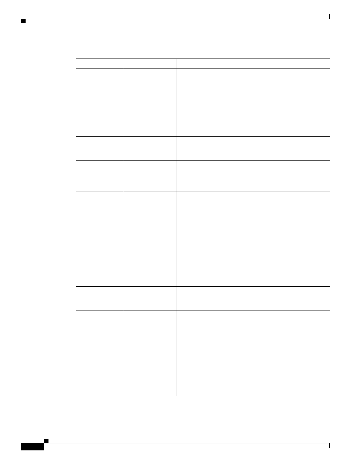
Table 1 Changes to This Document (continued)
Revision Date Change Summary
OL-6256-15 July 2011 Added information about new CRS-LSP Label Switch
Processor (LSP) card to the following sections:
• Chapter 1, “Cisco CRS Carrier Routing System 8-Slot
Line Card Chassis Overview”
• Chapter 4, “Installing and Removing Line Cards, PLIMs,
and Associated Components”
• Appendix A, “Cisco CRS Carrier Routing System 8-Slot
Line Card Chassis Specifications”
OL-6256-14 July 2011 Added new modular configuration AC cord clamp. Updated
Appendix A and added Appendix B. Minor editorial and
technical changes were also made.
OL-6256-13 April 2011 Added information about new CRS-8-PRP-6G and
CRS-8-PRP-12G Performance Route Processor (PRP) cards.
Technical updates and minor editorial changes were also
made.
OL-6256-12 November 2010 Updated grounding and modular configuration power
sections. Minor editorial and technical changes were also
made.
OL-6256-11 October 2010 Added information about the new MSC140 and FP140 line
cards; FQ123-140G switch fabric card; 20-port, 14-port,
8-port, and 4-port 10-GE XFP PLIMs; and the 1-port 100-GE
CFP PLIM. Minor editorial and technical changes were also
made.
OL-6256-10 September 2010 Added new procedures on installing and removing modular
configuration power components to Chapter 2, “Installing
and Removing Power Components.”
OL-6256-09 Jan 2010 Added installation of rear exhaust screen.
OL-6256-08 May 2008 Added new procedures on installing and removing a pillow
block to Chapter 4, “Installing and Removing Line Cards,
PLIMs, and Associated Components.”
OL-6256-07 February 2008 Minor technical changes.
OL-6256-06 August 2007 Updated the document with technical corrections. Also added
procedures in Chapter 5, “Installing and Removing Exterior
Components,” on installing the updated inlet grille.
OL-6256-05 October 2006 Updated the document with technical corrections. Also added
procedures in Chapter 5, “Installing and Removing Exterior
Components,” on installing and removing the front and rear
doors, installing and removing the inlet and exhaust grilles,
and added procedures for changing the location of the door
hinge and adjusting the width of the chassis doors if the doors
do not latch properly.
xvi
Cisco CRS Carrier Routing System 8-Slot Line Card Chassis Installation Guide
OL-6256-17
Page 17
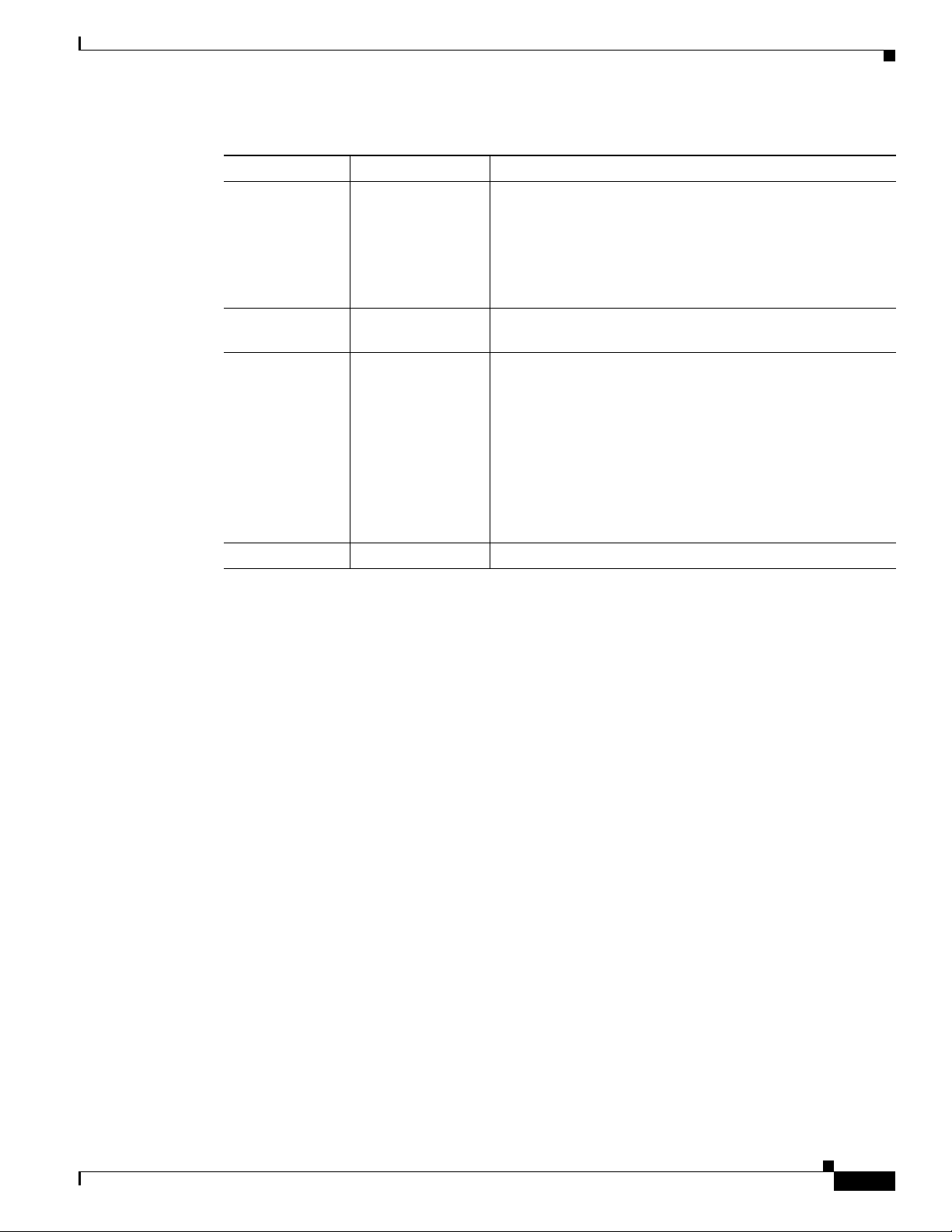
Table 1 Changes to This Document (continued)
Revision Date Change Summary
OL-6256-04 April 2006
OL-6256-03 December 2005 Updated Chapter 2, “Unpacking and Mounting the Chassis”
OL-6256-02 March 2005
OL-6256-01 December 2004 Initial release of the document.
• Removed Chapter 2, “Unpacking and Mounting the
Chassis” from this guide to consolidate this information
in the Cisco CRS Carrier Routing System 8-Slot Line
Card Chassis Unpacking, Moving, and Securing Guide.
• Changed the book title to Cisco CRS Carrier Routing
System 8-Slot Line Card Chassis Installation Guide.
to reflect new packaging.
• Updated Chapter 2, “Unpacking and Mounting the
Chassis” to include information on mounting the chassis
in the rack from the rear.
• Updated Chapter 3, “Installing and Removing Power
Components” to include new wiring information.
• Updated Chapter 5, “Installing and Removing MSCs,
PLIMs, and Associated Components” to include
information on installing and removing slot covers and
impedance carriers.
Obtaining Documentation and Submitting a Service Request
For information on obtaining documentation, submitting a service request, and gathering additional
information, see the monthly What’s New in Cisco Product Documentation, which also lists all new and
revised Cisco technical documentation, at:
http://www.cisco.com/en/US/docs/general/whatsnew/whatsnew.html
OL-6256-17
Cisco CRS Carrier Routing System 8-Slot Line Card Chassis Installation Guide
xvii
Page 18

xviii
Cisco CRS Carrier Routing System 8-Slot Line Card Chassis Installation Guide
OL-6256-17
Page 19

CHA P T ER
1
Cisco CRS Carrier Routing System 8-Slot Line Card Chassis Overview
This installation guide describes how to install the power, air circulation, line card, and external
components into and remove them from a Cisco CRS Carrier Routing System 8-Slot Line Card Chassis.
This chapter introduces the Cisco CRS 8-slot line card chassis at the highest level. It contains
illustrations of the front and rear of the chassis, complete with callouts to each hardware component. For
details on each subsystem discussed in this chapter, see Cisco CRS Carrier Routing System 8-Slot Line
Card Chassis System Description.
This chapter presents the following topics:
• Chassis Overview, page 1-1
• Chassis Components, page 1-2
• Chassis Slot Numbers, page 1-9
• Chassis Cable Management, page 1-10
• Chassis Cooling System, page 1-11
• Chassis Power System, page 1-12
• Safety Guidelines, page 1-12
• Preventing Electrostatic Discharge, page 1-13
Chassis Overview
The Cisco CRS 8-slot line card chassis can be installed in locations where the 16-slot system may not
fit (for example, colocation facilities, data centers, and many Tier II and Tier III locations). The routing
system consists of a single rack-mount chassis that contains the following major system components:
• Up to eight modular services cards (MSCs), forwarding processor (FP) cards, and label switch
processor (LSP) cards, also called line cards (up to eight)
• Physical layer interface modules, or PLIMs (up to eight, one for each line card)
• Route processor (RP) cards (up to two) or performance route processor (PRP) cards (up to two)
• Switch fabric cards (four required)
• SPA Interface Processors (SIPs) and Shared Port Adapters (SPAs) which can be installed instead of
PLIMs
OL-6256-17
Cisco CRS Carrier Routing System 8-Slot Line Card Chassis Installation Guide
1-1
Page 20

Chassis Components
Chapter 1 Cisco CRS Carrier Routing System 8-Slot Line Card Chassis Overview
–
SIP is a carrier card that is similar to a PLIM and inserts into a line card chassis slot and
interconnects to an MSC, FP, or LSP like a PLIM. Unlike PLIMs, SIPs provide no network
connectivity on their own.
–
SPA is a modular type of port adapter that inserts into a subslot of a compatible SIP carrier card
to provide network connectivity and increased interface port density. A SIP can hold one or
more SPAs, depending on the SIP type and the SPA size. POS/SDH and Gigabit Ethernet SPAs
are available.
• A chassis midplane that connects MSCs, FPs, or LSPs to their PLIMs and to switch fabric cards.
The LCC supports 40G, 140G, and 200G fabric cards, as follows:
• The Cisco CRS-1 Carrier Routing System uses fabric cards designed for 40 G operation
(CRS-8-FC/S or CRS-8-FC/M cards).
• The Cisco CRS-3 Carrier Routing System uses fabric cards designed for 140G operation
(CRS-8-FC140/S or CRS-8-FC140/M cards).
• The Cisco CRS-X Carrier Routing Sytsem uses fabric cards designed for 200G operation
(CRS-8-FC400/S cards in 200G mode).
A mixture of 40G, 140G, and 200G fabric cards is not supported except during migration.
Note Throughout this document, the generic term Cisco CRS Carrier Routing system refers to the Cisco
CRS-1, Cisco CRS-3, and Cisco CRS-X Carrier Routing Systems, unless otherwise specified.
Chassis Components
This section lists the main components of a Cisco CRS 8-slot line card chassis. It primarily identifies the
components that are considered field-replaceable units (FRUs), but where additional detail is useful
identifies subassemblies that are not field replaceable.
Figure 1-1 shows the front view of a Cisco CRS 8-slot line card chassis with a fixed configuration AC
power system installed. The front view of a Cisco CRS 8-slot line card chassis with a fixed configuration
DC power system installed is similar.
1-2
Cisco CRS Carrier Routing System 8-Slot Line Card Chassis Installation Guide
OL-6256-17
Page 21
Chapter 1 Cisco CRS Carrier Routing System 8-Slot Line Card Chassis Overview
122775
P
O
W
E
R
O
K
F
L
T
A
C
F
A
I
L
C
B
T
M
P
L
L
M
O
T
P
O
W
E
R
O
K
F
L
TA
C
F
A
I
L
C
B
T
M
P
L
L
MO
T
1
3
4
2
5
CISCO CRS-1
S
E
R
I
E
S
LINECARD CHASSIS
Figure 1-1 Front (PLIM) View of Line Card Chassis—Fixed Configuration Power Shown
Chassis Components
1 Cable management bracket 4 Air filter
2 Chassis vertical mounting brackets 5 Power System
3 PLIM and RP slots (RPs in middle 2 slots)
OL-6256-17
Cisco CRS Carrier Routing System 8-Slot Line Card Chassis Installation Guide
1-3
Page 22
Chassis Components
281369
CRS 8-Slot DC Rear
CRS 8-Slot AC Rear
Chapter 1 Cisco CRS Carrier Routing System 8-Slot Line Card Chassis Overview
Figure 1-2 shows the rear view of a Cisco CRS 8-slot line card chassis with fixed configuration AC and
DC power systems installed.
Figure 1-2 Rear (MSC) View of Line Card Chassis—Fixed Configuration Power Shown
1-4
Cisco CRS Carrier Routing System 8-Slot Line Card Chassis Installation Guide
OL-6256-17
Page 23
Chapter 1 Cisco CRS Carrier Routing System 8-Slot Line Card Chassis Overview
CRS 8-Slot DC Front
CRS 8-Slot AC Front
CISCO CRS-1
SER
I
E
S
LINECARD CHASSIS
281370
CISCO CRS-1
S
ERIES
LINECARD CHASSIS
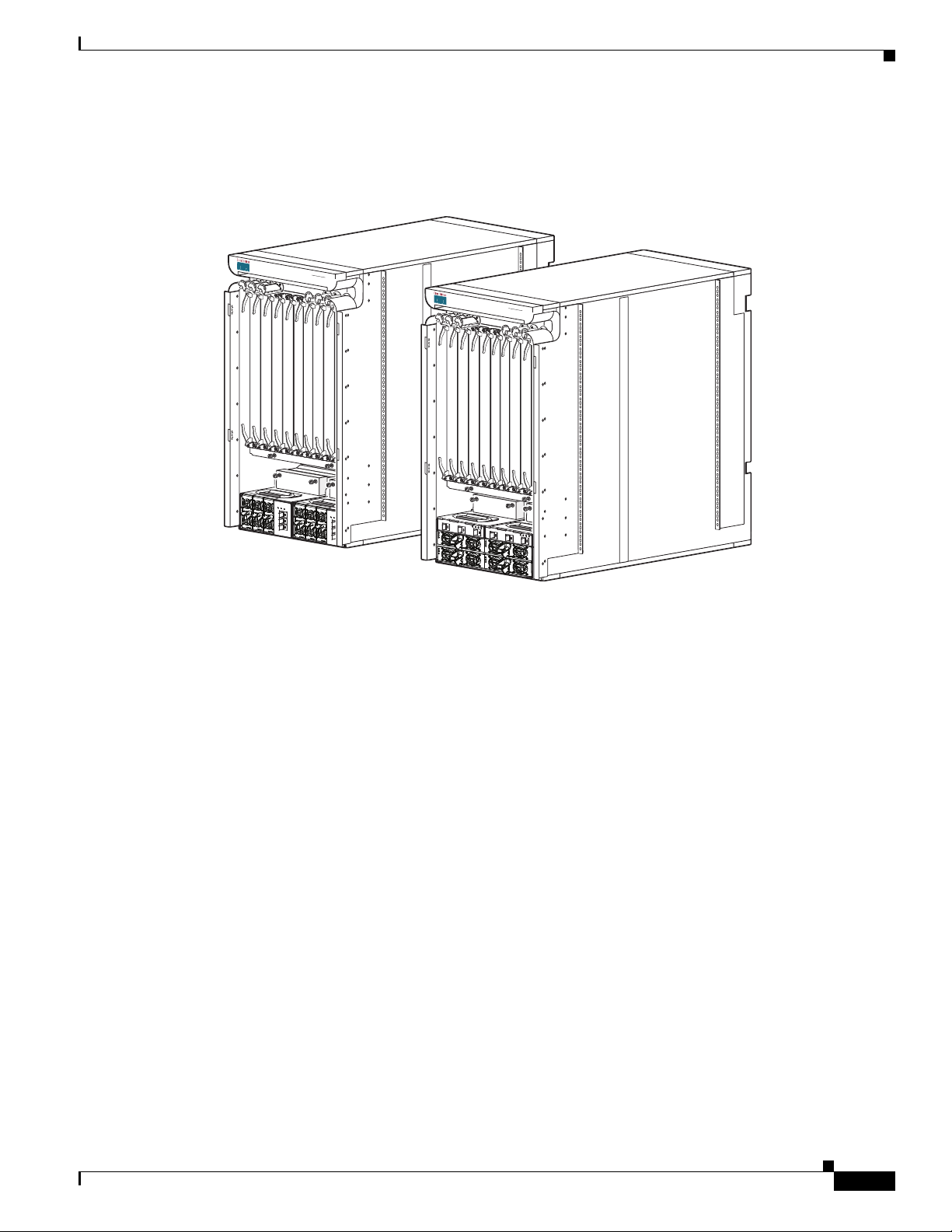
Figure 1-3 shows the front view of a Cisco CRS 8-slot line card chassis with modular configuration AC
and DC power systems installed.
Figure 1-3 Front (PLIM) View of Line Card Chassis—Modular Configuration Power Shown
Chassis Components
OL-6256-17
Cisco CRS Carrier Routing System 8-Slot Line Card Chassis Installation Guide
1-5
Page 24
Chassis Components
281371
CRS 8-Slot DC Rear
CRS 8-Slot AC Rear
Chapter 1 Cisco CRS Carrier Routing System 8-Slot Line Card Chassis Overview
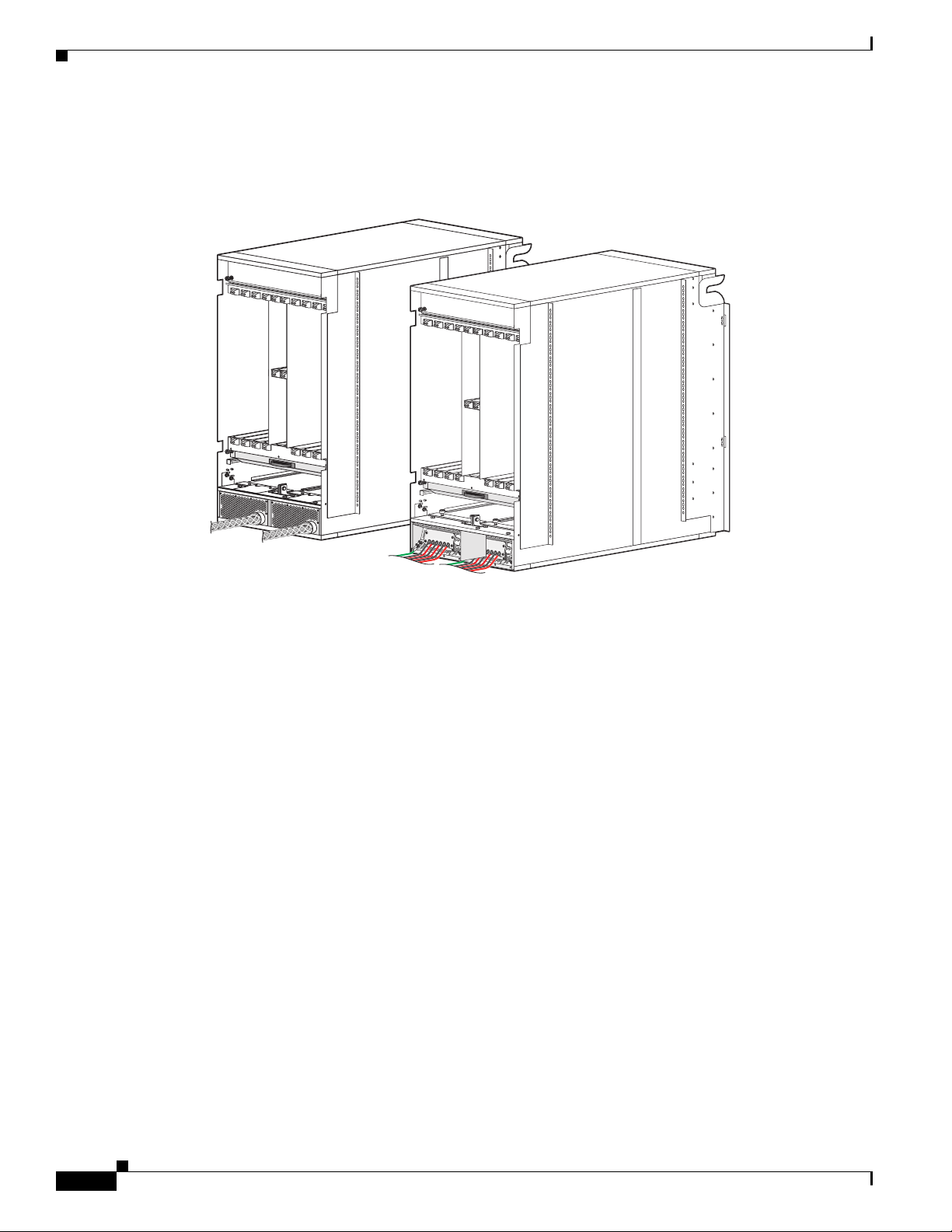
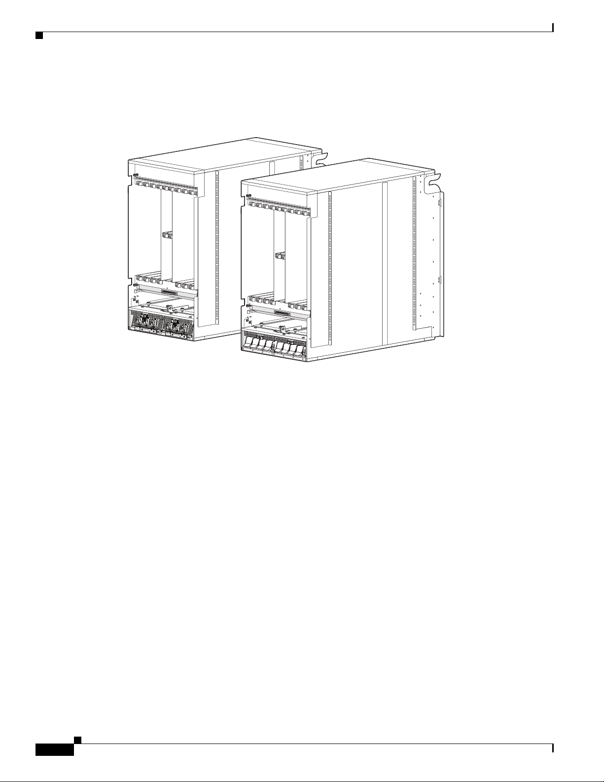
Figure 1-4 shows the rear view of a Cisco CRS 8-slot line card chassis with modular configuration AC
and DC power systems installed.
Figure 1-4 Rear (MSC) View of Line Card Chassis—Modular Configuration Shown
1-6
Cisco CRS Carrier Routing System 8-Slot Line Card Chassis Installation Guide
OL-6256-17
Page 25
Chapter 1 Cisco CRS Carrier Routing System 8-Slot Line Card Chassis Overview
122776
1
4
3
2
5
6
7
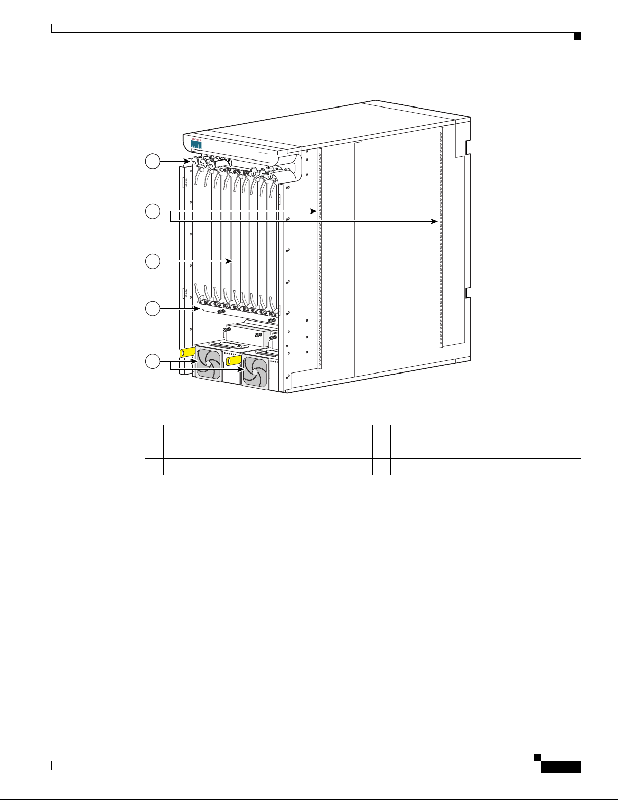
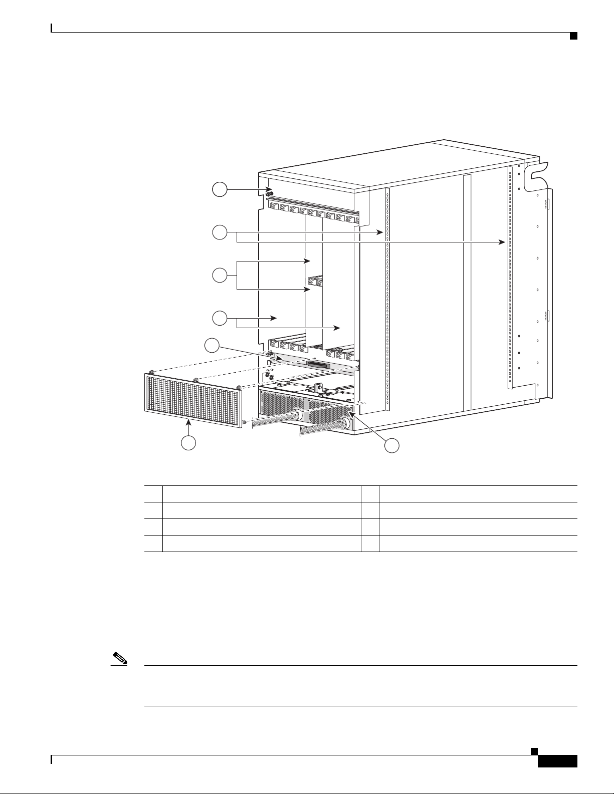
Figure 1-5 shows the rear view of a Cisco CRS 8-slot line card chassis with a fixed configuration AC
power system installed.
Figure 1-5 Rear (MSC) View of Line Card Chassis—Fixed Configuration Shown
Chassis Components
OL-6256-17
1 Upper fan tray (beneath cover) 5 Lower fan tray
2 Chassis vertical mounting brackets 6 Rear exhaust screen
3 Switch fabric card (half-height) slots 7 Power system
4 MSC slots
The Cisco CRS 8-slot line card chassis contains:
• As many as eightMSC, FP or LSP cards (all types are also called line cards), and eightPLIMs. The
line card and PLIM are an associated pair of cards that mate through the chassis midplane. The line
card provides the forwarding engine for Layer 3 routing of user data, and the PLIM provides the
physical interface and connectors for the user data. The line card can be associated with several
different PLIMs, which provide different interface speeds and technologies.
Note For a complete list of line cards, route processors, SPAs and SIPs, and interface modules supported in
the Cisco CRS 8-slot line card chassis, go to the Cisco Carrier Routing System Data Sheets at:
http://www.cisco.com/en/US/products/ps5763/products_data_sheets_list.html.
Cisco CRS Carrier Routing System 8-Slot Line Card Chassis Installation Guide
1-7
Page 26
Chassis Components
Chapter 1 Cisco CRS Carrier Routing System 8-Slot Line Card Chassis Overview
• A chassis midplane that connects line cards to their associated PLIMs. The midplane design allows
a line card to be removed from the chassis without having to disconnect the cables that are attached
to the associated PLIM. The midplane distributes power, connects the line cards to the switch fabric
cards, and provides control plane interconnections. The midplane is not field replaceable by the
customer.
• One or two route processor cards (RPs). The RPs provide the intelligence of the system by
functioning as the Cisco CRS 8-slot line card chassis system controller (serving as part of the control
plane in multi-chassis systems) and providing route processing. Only one RP is required for system
operation. For redundant operation, you can order a second RP as an option (CRS-8-RP/R). When
two RPs are used, only one RP is active at a time. The second RP acts as a “standby” RP, serving as
a backup if the active RP fails.
The RP also monitors system alarms and controls the system fans. LEDS on the front panel indicate
active alarm conditions.
A Performance Route Processor (PRP) is also available for the Cisco CRS 8-slot line card chassis.
Two PRPs perform the same functions as two RPs, but provide enhanced performance for both route
processing and system controller functionality.
Note A chassis may not be populated with a mix of RP and PRP cards. Both route processor cards
should be of the same type (RP or PRP).
• Upper and lower fan trays. The fans pull cool air through the chassis. A removable air filter is located
below the PLIM card cage at the front of the chassis.
• Four half-height switch fabric cards (SFCs). These cards provide the three-stage Benes switch fabric
for the routing system. The switch fabric performs the cross-connect function of the routing system,
connecting every MSC (and its associated PLIM) with every other MSC (and its associated PLIM)
in the system.
The switch fabric receives user data from one line card and PLIM pair and performs the switching
necessary to route the data to the appropriate egress line card and PLIM pair. The switch fabric is
divided into eight planes that are used to evenly distribute the traffic across the switch fabric. Each
switch fabric card implements two planes of the switch fabric.
• A power system that provides redundant power to the chassis. Two types of power systems are
available: fixed configuration power and modular configuration power. Both power configurations
use either AC or DC power. The fixed configuration power solution contains two power distribution
units (PDUs), with either one AC rectifier or one DC power entry modules (PEM) per PDU. The
modular configuration power solution contains two power shelves with either up to four DC power
modules (PMs) or up to three AC PMs per power shelf.
The PLIM side of the chassis is considered the front of the chassis, where user data cables attach to the
PLIMs and cool air enters the chassis. The MSC side, which is where warm air is exhausted, is
considered the rear of the chassis.
1-8
Cisco CRS Carrier Routing System 8-Slot Line Card Chassis Installation Guide
OL-6256-17
Page 27
Chapter 1 Cisco CRS Carrier Routing System 8-Slot Line Card Chassis Overview
Chassis Slot Numbers
This section identifies the location and slot numbers for major cards and modules (primarily the
field-replaceable units) that plug into the chassis.
Figure 1-6 shows the slot numbering on the front (PLIM) side of the Cisco CRS 8-slot line card chassis.
Figure 1-6 Line Card Chassis Slot Numbering—Front (PLIM) Side
012
3
RP 0
RP 1
456
7
Chassis Slot Numbers
Power A Power B
122778
As shown, the Cisco CRS 8-slot line card chassis numbers on the PLIM side of the chassis include the
card cage with:
• Eight PLIM slots: left to right, 0, 1, 2, 3, 4, 5, 6, 7
• Two route processor card slots, RP0 and RP1
• Power shelf A and power shelf B
OL-6256-17
Cisco CRS Carrier Routing System 8-Slot Line Card Chassis Installation Guide
1-9
Page 28
Chassis Cable Management
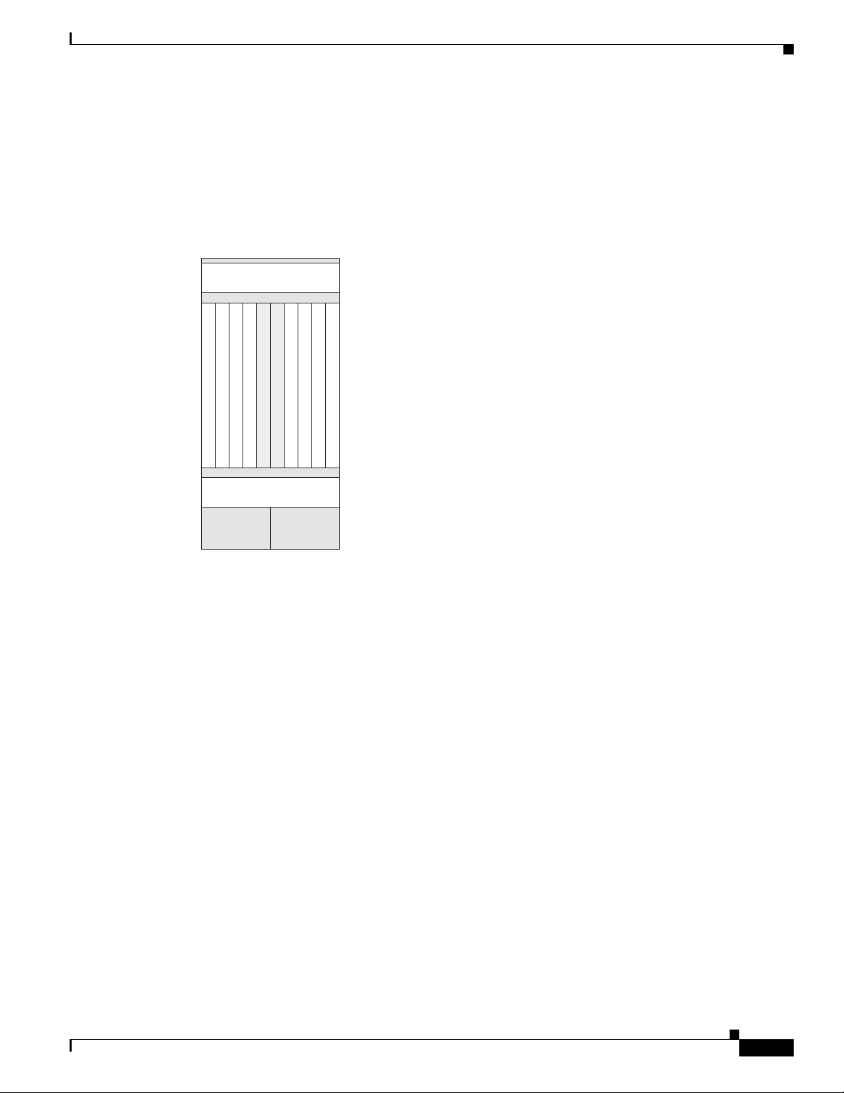
Figure 1-7 shows the slot numbers on the rear (MSC) side of the Cisco CRS 8-slot line card chassis.
Figure 1-7 Line Card Chassis Slot Numbers—Rear (MSC) Side
Chapter 1 Cisco CRS Carrier Routing System 8-Slot Line Card Chassis Overview
FAN 0
7654SM 0 SM 2
Power B Power A
SM 1 SM 33210
FAN 1
122779
As shown, the slot numbers on the MSC side of the chassis include:
• Fan tray 0 and fan tray 1
• Card cage, including:
–
Eight line card slots (0, 1, 2, 3, 4, 5, 6, 7)
–
Four half-height switch fabric card slots (SM0, SM1, SM2, and SM3)
• Power shelf A and Power shelf B
The MSC slot numbers are reversed from the PLIM slot numbers on the other side of the chassis.
Because an MSC mates with its associated PLIM through the midplane, MSC slot 0 is on the far right
side of the chassis looking at it from the rear (MSC) side.
PLIM slot 0 is on the far left side of the chassis, looking at if from the front (PLIM) side. MSC slot 0
and PLIM slot 0 mate with each other through the midplane, and so do all other MSC and PLIM slots (0
through 7).
Chassis Cable Management
The Cisco CRS 8-slot line card chassis has cable management features for the front (PLIM) side of the
chassis, just above the card cage. The horizontal cable management trays have a special telescoping
feature that allows them to be extended when the chassis is upgraded with higher-density cards. This
extension also helps when installing the cables in the chassis.
Note Do not install the front cover on the chassis when the telescoping feature is in use.
Cisco CRS Carrier Routing System 8-Slot Line Card Chassis Installation Guide
1-10
OL-6256-17
Page 29
Chapter 1 Cisco CRS Carrier Routing System 8-Slot Line Card Chassis Overview
122789
Figure 1-8 shows the cable management bracket.
Figure 1-8 Cable Management Bracket
Chassis Cooling System
Chassis Cooling System
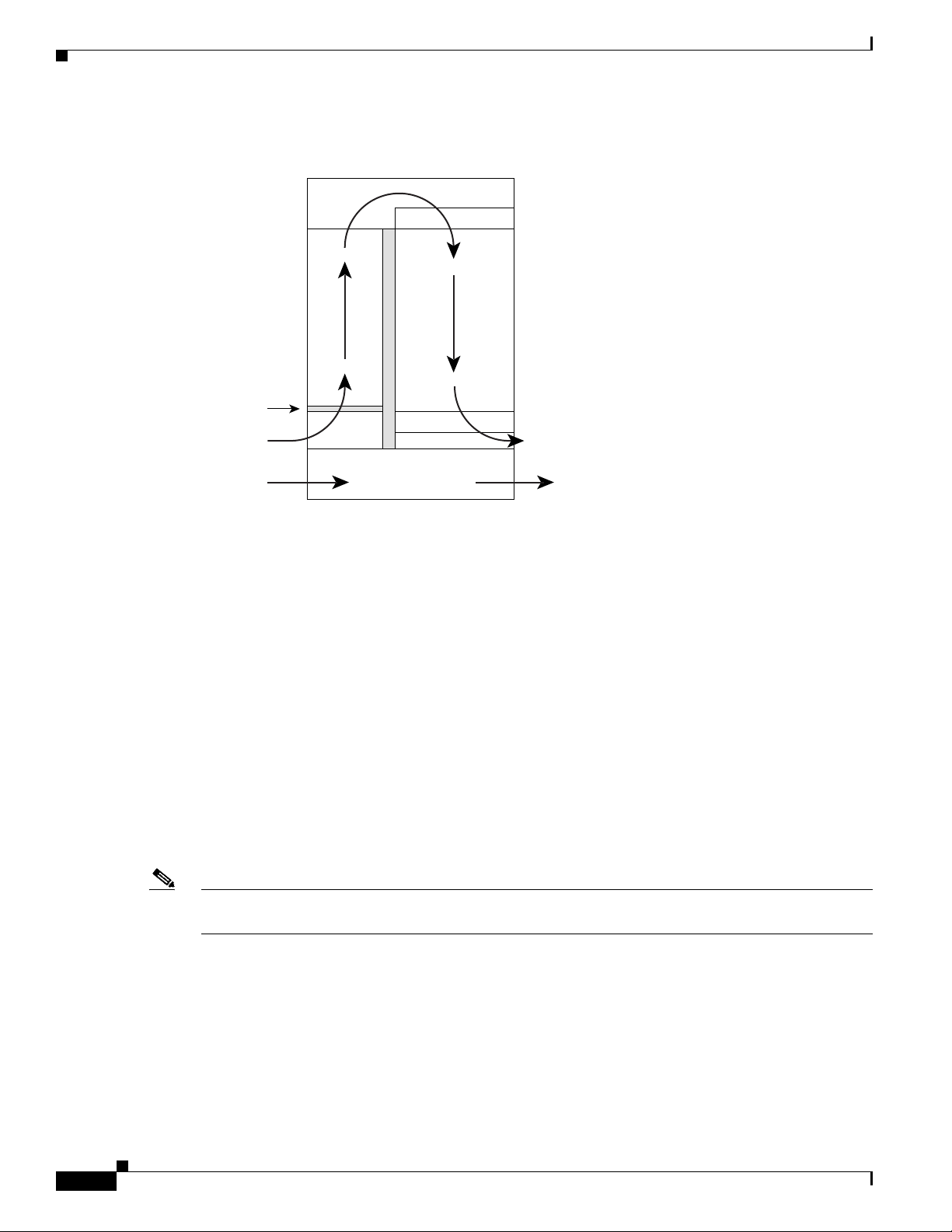
The chassis has two fan trays, each with four fans, that cool the chassis card cages. Cool air flows in at
the bottom front of the chassis and flows through the chassis card cages and through the fans in the fan
trays before being exhausted through the bottom rear of the chassis (see Figure 1-9). In addition, each
AC or DC power module at the bottom of the chassis has self-contained fans that pull in cool air from
the front of the chassis and exhaust warm air out the rear.
A replaceable air filter is located on the front of the chassis below the PLIM card cage. Each fixed
configuration power module also has a replaceable air filter that attaches to the module at the front
(PLIM) side of the chassis. How often the air filters should be replaced depends on the facility
environment. In a dirty environment, or when you start getting frequent temperature alarms, you should
always check the intake grills for debris, and then check the air filters to see if they need to be replaced.
Note We recommend that you check the air filters once a month. Replace a filter when you notice a significant
amount of dust.
OL-6256-17
Cisco CRS Carrier Routing System 8-Slot Line Card Chassis Installation Guide
1-11
Page 30
Chassis Power System
122784
Fan
Air enters
PLIM side
Power system
Fan
Air exits MSC and
fabric card side
Front Rear
Air filter
Chapter 1 Cisco CRS Carrier Routing System 8-Slot Line Card Chassis Overview
Figure 1-9 Airflow Through 8-Slot Line Card Chassis
Chassis Power System
Two types of power systems are available for the Cisco CRS 8-slot line card chassis: fixed configuration
power and modular configuration power. Both power systems can be powered by either AC or DC power.
The chassis power system takes the facility power and converts it to the DC voltage necessary to power
chassis components.
For more information, refer to Chapter 2, “Installing and Removing Power Components.”
Safety Guidelines
Before you perform any procedure in this document, review the safety guidelines in this section to avoid
injuring yourself or damaging the equipment. The following guidelines are for your safety and to protect
equipment. The guidelines do not include all hazards. Be alert.
Note Review the safety warnings listed in Regulatory Compliance and Safety Information that are applicable
to your router before installing, configuring, or troubleshooting any installed card.
• Keep the work area clear and dust-free during and after installation. Do not allow dirt or debris to
enter into any laser-based components.
• Do not wear loose clothing, jewelry, or other items that could get caught in the router while working
with line cards, or their associated components.
• Cisco equipment operates safely when used in accordance with its specifications and product-usage
instructions.
• Be sure to power down a fixed configuration PDU or modular configuration power shelf before
removing it from the chassis.
1-12
Cisco CRS Carrier Routing System 8-Slot Line Card Chassis Installation Guide
OL-6256-17
Page 31

Chapter 1 Cisco CRS Carrier Routing System 8-Slot Line Card Chassis Overview
Preventing Electrostatic Discharge
Electrostatic discharge (ESD) damage, which can occur when electronic cards or components are
improperly handled, results in complete or intermittent failures. We recommend to use an
ESD-preventive strap whenever you handle network equipment or one of its components.
Following are guidelines for preventing ESD damage:
• Always use an ESD-preventive wrist or ankle strap and ensure that it makes good skin contact.
Connect the equipment end of the connection cord to an ESD connection socket on the router or to
a bare metal surface on the chassis.
• Handle a card by its ejector levers, when applicable, or the card’s metal carrier only; avoid touching
the board or connector pins.
• Place a removed card board-side-up on an antistatic surface or in a static-shielding bag. If you plan
to return the component to the factory, immediately place it in a static-shielding bag.
• Avoid contact between the card and clothing. The wrist strap protects the board only from ESD
voltage on the body; ESD voltage on clothing can still cause damage.
Preventing Electrostatic Discharge
OL-6256-17
Cisco CRS Carrier Routing System 8-Slot Line Card Chassis Installation Guide
1-13
Page 32

Preventing Electrostatic Discharge
Chapter 1 Cisco CRS Carrier Routing System 8-Slot Line Card Chassis Overview
1-14
Cisco CRS Carrier Routing System 8-Slot Line Card Chassis Installation Guide
OL-6256-17
Page 33

Installing and Removing Power Components
This chapter provides instructions on how to install and remove Cisco CRS Carrier Routing System
8-slot line card chassis power components.
Power Systems Overview
There are two options for power systems: the fixed configuration power system and the modular
configuration power system. Power components are not interchangeable between the fixed and modular
configuration power system.
• Fixed configuration power system consists of two power distribution units (PDUs) and either DC
power entry modules (PEMs) or AC rectifiers. The AC version requires 3-phase AC-Delta or
AC-Wye input power to the PDU. The PDU distributes facility power to the AC rectifier or DC PEM,
which in turn provides processed power to the chassis. A removable air filter is located on the front
of each DC PEM and AC rectifier. The fixed configuration power system includes SNMP MIBS and
XML support.
CHA P T ER
2
• Modular configuration power system consists of two power shelves and either AC or DC power
modules (PMs). However, unlike the fixed configuration power system, the AC version of the
modular configuration power system requires single-phase AC input power to power the shelves. If
you have 3-phase AC-Delta or AC-Wye at your equipment, a Cisco CRS PDU will be required to
convert 3-phase AC input power to single-phase AC input power for the power shelf. At the shelf
level, the power system provides 2N redundancy; the PMs themselves provide load-share
redundancy. The modular configuration power system also includes SNMP MIBs and XML support.
Note In a fixed configuration AC or DC power system, PDU refers to the power component that connects to
the AC rectifier or DC PEM.
Note In a modular configuration AC power system, PDU refers to the Cisco CRS PDU that converts 3-phase
AC-Wye or AC-Delta input power to single-phase AC input power for the modular configuration AC
power shelf. For further information, refer to Cisco CRS 3-Phase AC Power Distribution Unit
Installation Guide.
OL-6256-17
Cisco CRS Carrier Routing System 8-Slot Line Card Chassis Installation Guide
2-1
Page 34

Chapter 2 Installing and Removing Power Components
Power Component Information Common to Two Types of Power System
This chapter presents the following topics:
• Power Component Information Common to Two Types of Power System, page 2-2
• How to Install or Remove Fixed Configuration Power Components, page 2-13
• How to Install or Remove Modular Configuration Power Components, page 2-25
• Converting a Chassis from Fixed Configuration Power to Modular Configuration Power, page 2-54
Power Component Information Common to Two Types of Power
System
This section contains information shared by the fixed configuration power components and the modular
configuration power components in the following topics:
• Basic Chassis Power Details, page 2-2
• Bonding and Grounding Guidelines, page 2-4
• How to Install the Chassis Ground Cable, page 2-5
• DC Power Systems, page 2-6
• AC Power Systems, page 2-11
Basic Chassis Power Details
The Cisco CRS 8-slot line card chassis can be configured with either a DC-input power subsystem or an
AC-input power subsystem. The chassis power system provides the necessary power for chassis
components. Site power requirements differ, depending on the source voltage used.
A fixed configuration AC PDU connects to an AC rectifier, while a fixed configuration DC PDU
connects to a DC PEM. A modular configuration AC power shelf houses up to 3 AC PMs, while a
modular configuration DC power shelf houses up to 4 DC PMs. It is required that you use only one type
of power shelf in a chassis at a time.
Note In a modular configuration power system, both AC and DC power supplies are referred to as power
modules (PMs).
Warning
This unit might have more than one power supply connection. All connections must be removed to
de-energize the unit.
Statement 1028
2-2
Cisco CRS Carrier Routing System 8-Slot Line Card Chassis Installation Guide
OL-6256-17
Page 35

Chapter 2 Installing and Removing Power Components
Fixed Configuration Power System
Three types of PDUs exist for fixed configuration power system:
• AC Wye PDU
• AC Delta PDU
• DC PDU
The AC PDU connects to the AC rectifier, while the DC PDU connects to the DC PEM. Although there
are differences among the different PDU types (AC Wye, AC Delta, and DC), they are installed in the
same manner. For detailed information, see the “How to Install or Remove Fixed Configuration Power
Components” section on page 2-13.
Note The fixed configuration PDUs arrive preassembled in the chassis. AC power cords arrive preattached but
the DC power cables need to be installed.
Caution Use only one type of fixed configuration PDU—AC Wye, AC Delta, or DC—and its mating AC rectifier
or DC PEM in a chassis at one time.
Power Component Information Common to Two Types of Power System
Modular Configuration Power System
The modular configuration AC power shelves connect to AC PMs, while the modular configuration DC
power shelves connect to DC PMs. Although there are differences between the two different power shelf
types (AC and DC), they are installed in the same manner. Similarly, the modular configuration AC and
DC PMs are installed in the same manner. For detailed information, see the “How to Install or Remove
Modular Configuration Power Components” section on page 2-25.
Caution Use only one type of modular configuration power shelf—AC or DC—and its mating AC or DC PMs in
a chassis at one time.
Precautions and Recommendations
Follow these precautions and recommendations when planning power connections to the router:
• Check the power at your site before installation and periodically after installation to ensure that you
are receiving clean power. Install a power conditioner, if necessary.
• Properly ground your system to avoid damage from lightning and power surges.
Note For the fixed configuration power system, although PDUs may be installed or removed without powering
down the system, for safety purposes we recommend that you power down the system before you install
or remove a PDU.
OL-6256-17
For the modular configuration power system, although power shelves may be installed or removed
without powering down the system, for safety purposes we recommend that you power down the system
before you install or remove a power shelf.
Cisco CRS Carrier Routing System 8-Slot Line Card Chassis Installation Guide
2-3
Page 36

Power Component Information Common to Two Types of Power System
Bonding and Grounding Guidelines
The router chassis has safety earth ground connections in conjunction with the power cabling to the fixed
configuration PDUs. Modular configuration power supports chassis grounding only. The chassis allows
you to connect the central office ground system or interior equipment ground system to the bonding and
grounding receptacles on the router chassis, when either a fixed or modular configuration power system
is installed. Six chassis grounding points are provided at the rear (MSC) side of the chassis, as shown in
Figure 2-1. Each side of the chassis has one pair of threaded ground studs located on the inside of the
chassis and two sets of grounding receptacles located on the outside of the chassis. These ground points
are also called the network equipment building system (NEBS) bonding and grounding points.
Note These bonding and grounding receptacles satisfy the Telcordia NEBS requirements for bonding and
grounding connections.
Figure 2-1 NEBS Bonding and Grounding Points (Rear of Chassis) - Fixed Configuration AC
Power Shown
Chapter 2 Installing and Removing Power Components
1
2
1 NEBS bonding and grounding points (inside chassis)
2 NEBS bonding and grounding points (outside chassis)
Caution Do not remove the chassis ground cable unless the chassis is being replaced.
122792
2-4
Cisco CRS Carrier Routing System 8-Slot Line Card Chassis Installation Guide
OL-6256-17
Page 37

Chapter 2 Installing and Removing Power Components
How to Install the Chassis Ground Cable
This section describes how to install the ground cable on the Cisco CRS 8-slot line card chassis.
Prerequisites
To connect the routing system to a network equipment building system (NEBS)-compliant bonding and
grounding system at the site, you must have the following:
• Minimum of one grounding lug that has two M6 bolt holes with 0.63-inch (5/8 inch) (1.6 cm) of
spacing between them, center to center, and a 6-AWG multistrand copper cable. The lug is similar
to the type used for the DC-input power supply leads, as shown in Figure 2-4.
• Four M6 or equivalent hex-head nuts with integrated locking washers are shipped pre-installed on
the inside of the chassis.
• Eight M6 or equivalent hex-head bolts with integrated locking washers are shipped pre-installed on
the outside of the chassis.
• Ground cable routed upwards or downwards, per customer installation requirements. Although we
recommend at least 6-AWG multistrand copper cable, the actual cable diameter and length depend
on your router location and site environment. This cable is not available from Cisco Systems; it is
available from any commercial cable vendor. The ground cable should be sized according to local
and national installation requirements.
Power Component Information Common to Two Types of Power System
Caution The DC Return of the Cisco CRS 8-slot chassis should remain isolated from the system frame and
chassis (DC-I: Isolated DC Return).
Required Tools and Equipment
You need the following tools to perform this task:
• One ground lug for equipment-side ground connection. In a rack application, the rack-side of the
ground cable will also require a lug.
• Ground cable
• Crimping tool and lug specific die
• 10-mm 6 pt. combination wrench
• Torque wrench with 10-mm 6 pt. socket and rated accuracy at 30 in.-lb (3.39 N-m)
Steps
To attach the ground cable to the chassis, perform the following steps:
Step 1 Use the crimping tool mandated by the lug manufacturer to crimp the lug to the ground cable.
Step 2 Using the 10-mm wrench, attach the ground cable to one of the grounding points at the rear of the
chassis. Then use the torque wrench to tighten to a torque of 30 in.-lb (3.39 N-m). Figure 2-2 shows how
the ground cable is attached to the ground points on the outside of the chassis.
OL-6256-17
Cisco CRS Carrier Routing System 8-Slot Line Card Chassis Installation Guide
2-5
Page 38

Power Component Information Common to Two Types of Power System
254895
Figure 2-2 Ground Cables Attached to Chassis Grounding Points
Chapter 2 Installing and Removing Power Components
1 NEBS bonding and grounding points (inside chassis)
2 NEBS bonding and grounding points (outside chassis)
DC Power Systems
Each DC powered chassis contains two fixed configuration PDUs or two modular configuration power
shelves for 2N redundancy.
• In the fixed configuration power system, each PDU accepts one DC PEM for 2N redundancy. The
PDUs and PEMs are field replaceable. The PDUs contain the input power connectors.
• In the modular configuration power system, each power shelf accepts up to four DC PMs. The power
shelves and DC PMs are field replaceable. The power shelves contain the input power connectors.
Note Depending on the hardware deployed at your site, your system may not consume the maximum
power supplied by the power system.
Fixed Configuration DC Power
The Cisco CRS 8-slot line card chassis DC power system provides 7,500 watts to power the chassis. Each
DC PDU is connected to three pairs of DC power feeds and powers a single DC PEM. Input DC power
enters the PDU and is passed to the PEM, which provides power to the components in the chassis.
• Each DC PEM has its own circuit breaker.
• The fixed configuration power system distributes power in power zones.
2-6
• The DC PDUs and DC PEMs are field replaceable.
Cisco CRS Carrier Routing System 8-Slot Line Card Chassis Installation Guide
OL-6256-17
Page 39

Chapter 2 Installing and Removing Power Components
129533
1
Unlike the Cisco CRS 16-slot line card chassis, the Cisco CRS 8-slot line card chassis does not contain
an alarm module. A microprocessor in the DC PEM monitors the status of each DC PEM. The
microprocessor communicates with the system controller on the route processor (RP) card. LEDs on the
front panel of the RP card indicate active alarm conditions.
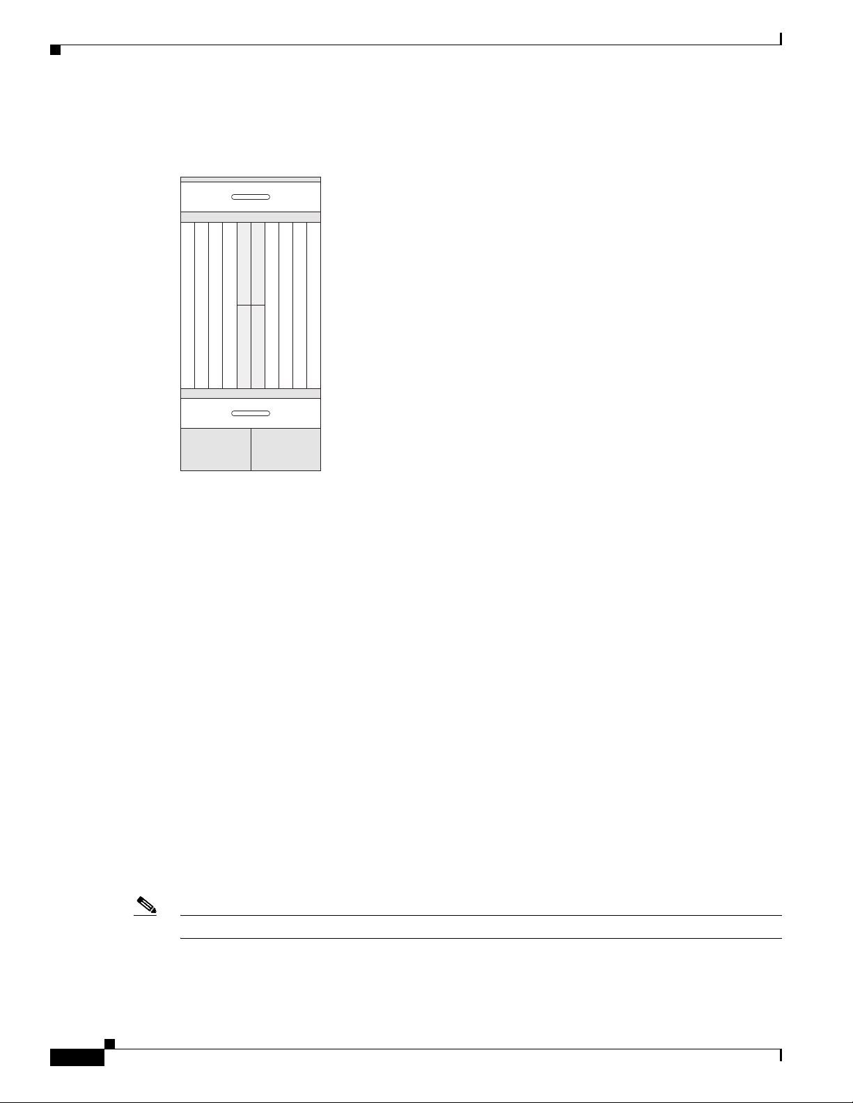
The DC PDU is shipped with a plastic safety cover over the input terminal block, as shown in Figure 2-3.
This safety cover has two parts, each part held on to the PDU with a Phillips screw. We recommend
removing the safety cover only when wiring and unwiring the chassis. The safety cover is slotted in such
a way that the cables can only come out on the bottom portion of the cover.
Figure 2-3 Fixed Configuration DC PDU with Plastic Safety Cover
Power Component Information Common to Two Types of Power System
1 Each set of cables (RTN and –48 V/–60 V) is a single VDC input.
Each PDU requires three DC inputs of –48/–60 VDC (nominal), 60 A service. The PDU has three sets
of double-stud terminals (-48/-60 VDC Lines and -48/-60 VDC Returns) for connecting to the VDC inputs.
Each DC PDU should be connected to a different central office DC power source:
• One PDU should be connected to three –48/–60 VDC “A” buses.
• Other PDU should be connected to three –48/–60 VDC “B” buses.
If DC power to a PDU fails, the other PDU provides enough power for the chassis. This 2N power
redundancy enables the routing system to operate in spite of single power failure.
For DC power cables, we recommend that you use commensurately rated, high-strand-count copper
cable. These cables are not available from Cisco Systems; they are available from any commercial
vendor. DC power cables must be terminated by cable lugs at the power shelf end.
Note All six -48/-60 VDC Return input cables for one chassis should have the same cable gauges and the
lengths should be matched within 10 percent of deviation.
The grounding lugs should be dual-hole and able to fit over M6 terminal studs at 0.63 in (1.6 cm) centers,
as shown in Figure 2-4 (for example, Panduit part number LCD2-14A-Q, or equivalent).
OL-6256-17
Cisco CRS Carrier Routing System 8-Slot Line Card Chassis Installation Guide
2-7
Page 40

Power Component Information Common to Two Types of Power System
Crimp area
310354
2.40
+/- .06
0.60
+/- .04
0.10
+/- .01
0.25
+/- .04
0.380.63
+/- .02
End View
Ø 0.27
+/- .02
2 holes
All measurements in inches
310355
2.11
REF
2.11
REF
0.60
+/- .04
0.25
+/- .04
0.38
REF
0.88
+/- .04
.10
+/- .01
1.18
REF
45° +/- 5°
0.63
+/- .02
Ø 0.27
+/- .02
2 holes
All measurements in inches
Figure 2-4 DC Power Grounding Cable Lug
The terminal lugs (in other words, all lugs not used for grounding) should be 45-degree angled,
industry-standard dual-hole compressions lugs, and able to fit over M6 terminal studs at 0.63 in (1.6 cm)
centers, as shown in Figure 2-5.
Note In the fixed configuration power system, power cables have a 20 in.-lb (2.26 N-m) torque value and
ground cables have a 30 in.-lb (3.39 N-m) torque value. The PDU mounting screws have a 9 in.-lb (1.04
N-m) torque value.
Chapter 2 Installing and Removing Power Components
Figure 2-5 DC Power Cable Lug
2-8
Cisco CRS Carrier Routing System 8-Slot Line Card Chassis Installation Guide
OL-6256-17
Page 41

Chapter 2 Installing and Removing Power Components
The color coding of the source DC power cable leads depends on the color coding of the site DC power
source. Typically, green or green and yellow indicates that the cable is a ground cable. Follow your local
practices for cable color code and markings. You must ensure that the power cables are connected to the
DC-input power shelf terminal studs in the proper positive (+) and negative (–) polarity.
In some cases, the source DC cable leads might have a positive (+) or negative (–) label, but you must
verify the polarity by measuring the voltage between the DC cable leads. When making the
measurement, the positive (+) lead and negative (–) lead must always match the (+) and (–) labels on the
PDU.
Caution When installing DC power cables, make sure that the polarity of the DC input wiring is correct.
For additional power details, see Appendix A, “Cisco CRS Carrier Routing System 8-Slot Line Card
Chassis Specifications” or Cisco CRS Carrier Routing System 8-Slot Line Card Chassis System
Description.
Modular Configuration DC Power
The Cisco CRS 8-slot line card chassis modular configuration DC power system can provide up to
8,400 W to power the line card chassis. The modular configuration DC power system uses A or B power
shelves to provide reliable, 2N redundant power to all chassis components.
Power Component Information Common to Two Types of Power System
Note Depending on the hardware deployed at your site, your system may not consume the maximum power
supplied by the power system.
The Cisco CRS 8-slot line card chassis does not contain an alarm module. The DC PM monitors PM
status and processes alarm functions. The PM distributes power and passes PM status signals to the
system. Alarms are processed through the route processor (RP). LEDs on the front panel of the RP card
indicate active alarm conditions.
If DC power to one modular configuration power shelf fails, the other power shelf provides enough
power for the chassis. This 2N power redundancy enables the routing system to operate in spite of single
power failure.
Each power shelf operates with up to four DC inputs of –48/–60 VDC (nominal), 60 A. The power shelf
accepts input DC power in the range –40 to –72 VDC.
OL-6256-17
Cisco CRS Carrier Routing System 8-Slot Line Card Chassis Installation Guide
2-9
Page 42

Power Component Information Common to Two Types of Power System
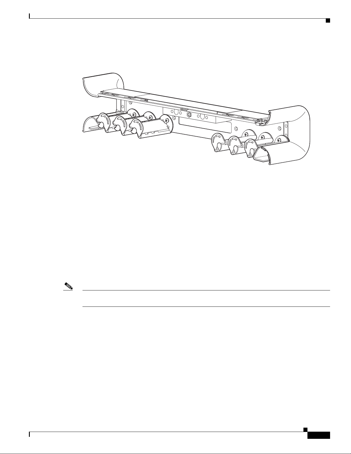
Figure 2-6 shows the wiring on the rear of a modular configuration DC power shelf.
Figure 2-6 Modular Configuration DC Power Shelf Wiring
Chapter 2 Installing and Removing Power Components
281336
We recommend that the terminal block covers, shown in Figure 2-6, should only be removed when
wiring and unwiring the power shelf. The terminal block cover is slotted in such a way that cables can
only come out the bottom portion of each cover.
The power supply terminal block lug opening width is 0.63 inch (1.6 cm). The terminal posts are
centered 0.63 inches (5/8 inch) (1.6 cm) apart and are M6-threaded. We recommend that you use an
appropriately sized 180-degree angle (straight) industry standard 2-hole, standard barrel compression
lug, as shown in Figure 2-7, or an appropriately sized 45-degree angle industry standard 2-hole, standard
barrel compression lug, as shown in Figure 2-8.
Figure 2-7 180-Degree (Straight) DC Power Cable Lug
All measurements in inches
310354
End View
0.60
+/- .04
0.10
+/- .01
Ø 0.27
+/- .02
2 holes
0.25
+/- .04
2.40
+/- .06
Crimp area
0.380.63
+/- .02
2-10
Cisco CRS Carrier Routing System 8-Slot Line Card Chassis Installation Guide
OL-6256-17
Page 43

Chapter 2 Installing and Removing Power Components
Figure 2-8 45-Degree DC Power Cable Lug
All measurements in inches
Power Component Information Common to Two Types of Power System
2.11
REF
0.60
+/- .04
.10
+/- .01
Ø 0.27
+/- .02
2 holes
0.25
+/- .04
0.63
+/- .02
+/- .04
2.11
REF
0.38
REF
0.88
1.18
REF
45° +/- 5°
310355
Note In the modular configuration power system, DC power cables have a torque value of 20 in.-lb (2.26 N-m)
and chassis ground cable connectors have a torque value of 30 in.-lb (3.39 N-m).
For additional power details, see Appendix A, “Cisco CRS Carrier Routing System 8-Slot Line Card
Chassis Specifications” or Cisco CRS Carrier Routing System 8-Slot Line Card Chassis System
Description.
AC Power Systems
Each AC powered chassis contains two fixed configuration AC PDUs or two modular configuration AC
power shelves for 2N redundancy.
• In the fixed configuration power system, each PDU accepts one AC power rectifier. The PDUs and
AC power rectifiers are field replaceable.
• In the modular configuration power system, each power shelf can contain up to three AC PMs. The
power shelves and the AC PMs are field replaceable.
Note Depending on the hardware deployed at your site, your system may not consume the maximum power
supplied by the power system.
OL-6256-17
Cisco CRS Carrier Routing System 8-Slot Line Card Chassis Installation Guide
2-11
Page 44

Power Component Information Common to Two Types of Power System
Fixed Configuration AC Power
An AC-powered Cisco CRS 8-slot line card chassis contains two AC power distribution units (PDUs)
and two AC rectifier modules. Each AC PDU is connected to a 3-phase (200 to 240) input VAC power
source and connects to a single 7500-watt AC rectifier module that is field replaceable. Each AC rectifier
module converts input AC power to the 54.5 VDC used by the Cisco CRS 8-slot line card chassis. Each
rectifier has its own circuit breaker.
To provide 2N power redundancy for the Cisco CRS 8-slot line card chassis, each PDU and AC rectifier
pair is connected to a different AC power source. During normal operation when both power sources are
operational, both PDUs and rectifiers function together to power the chassis. However, if a power source
fails, the other power source provides the other PDU and rectifier pair with enough input power to power
the chassis. This 2N power redundancy enables the routing system to operate despite the power failure.
Two versions of the AC PDU are available to accommodate AC input power in either the Delta or Wye
configuration. Each PDU has a different Cisco part number. The PDUs are shipped with AC power cords
that are 14 feet (4.3 m) long.
Unlike the Cisco CRS 16-slot line card chassis, the Cisco CRS 8-slot line card chassis does not contain
an alarm module. A microprocessor in the AC rectifier monitors the status of each AC rectifier. The
microprocessor communicates with the system controller on the RP card. LEDs on the front panel of the
RP card indicate active alarm conditions.
Chapter 2 Installing and Removing Power Components
The AC PDUs have the following input VAC power requirements:
• AC Wye input: 3-phase, 200 to 240 VAC nominal (phase-to-neutral), 50 to 60 Hz,
16 A (International) or 20 A (North America). The PDU is rated for 14-amp service, and accepts AC
input of 16 or 20 A.
The Wye power cord has a 5-pin IEC 60309 plug that is rated for 400 VAC, 16 or 20 A, (3W + N +
PE). The power cord plugs into a similarly rated IEC 60309 receptacle.
• AC Delta input: 3-phase, 200 to 240 VAC nominal (phase-to-phase), 50 to 60 Hz, 30 A. The PDU is
rated for 24-amp service, and accepts AC input of 30 A.
The Delta power cord has a 4-pin NEMA L15-30P plug that is rated for 250 VAC, 30 A (3W + PE).
The power cord plugs into a similarly rated NEMA L15-30R locking-type receptacle.
For additional power details, see Appendix A, “Cisco CRS Carrier Routing System 8-Slot Line Card
Chassis Specifications” or Cisco CRS Carrier Routing System 8-Slot Line Card Chassis System
Description.
Modular Configuration AC Power
The Cisco CRS 8-slot line card chassis modular configuration AC power system can provide up to
9,000 W to power the line card chassis.
Note Depending on the hardware deployed at your site, your system may not consume the maximum power
supplied by the power system.
2-12
The modular configuration power system provides the following features:
• AC power shelf redundancy
• PM load-share redundancy
• Elimination of power zone distribution, while maintaining zone protection
• Capacity for future growth
Cisco CRS Carrier Routing System 8-Slot Line Card Chassis Installation Guide
OL-6256-17
Page 45

Chapter 2 Installing and Removing Power Components
The modular configuration AC power systems use A or B power shelves to provide reliable, 2N
redundant power to all chassis components.
The Cisco CRS 8-slot line card chassis does not contain an alarm module. The AC PM monitors PM
status and processes alarm functions. The AC PM distributes power and passes PM status signals to the
system. Each PM has its own integrated fuse to protect the system, and each PM is plugged into its own
power outlet. Alarms are processed through the RP. LEDs on the front panel of the RP indicate active
alarm conditions.
Unlike the fixed configuration AC power system, which requires 3-phase AC Delta or AC Wye input
power, the modular configuration AC power system requires single-phase AC input power. If you have
3-phase AC Delta or AC Wye at your equipment, a Cisco CRS PDU will be required to convert 3-phase
AC input power to single-phase AC input power for the power shelf. For further information, refer to
Cisco CRS 3-Phase AC Power Distribution Unit Installation Guide.
The modular configuration AC power shelf has the following input VAC power requirements:
• Single-phase, 200 to 240 VAC nominal, 50 to 60 Hz, 16 A.
Each power shelf contains three IEC-320-C22 receptacles which can accept up to three
IEC-320-C21 connector female cords.
How to Install or Remove Fixed Configuration Power Components
Note In order to maintain a balanced 3-phase power load, three AC PMs are required to be installed in a Cisco
CRS 8-slot line card chassis AC modular configuration power shelf.
Note If single-phase AC power is available at your site, we recommend that you use appropriate short-circuit
protection in compliance with national and local electrical codes.
For additional power details, see Appendix A, “Cisco CRS Carrier Routing System 8-Slot Line Card
Chassis Specifications” or Cisco CRS Carrier Routing System 8-Slot Line Card Chassis System
Description.
How to Install or Remove Fixed Configuration Power
Components
This section contains the following procedures:
• Before Powering the Chassis Up or Down, page 2-14
• Converting from One Fixed Configuration Power System to Another, page 2-14
• Installing a PDU
• Removing a PDU
OL-6256-17
• Installing DC PDU Cables, page 2-19
• Removing DC PDU Wiring, page 2-21
• Installing a DC PEM or AC Rectifier
• Removing a DC PEM or AC rectifier
Cisco CRS Carrier Routing System 8-Slot Line Card Chassis Installation Guide
2-13
Page 46

How to Install or Remove Fixed Configuration Power Components
Note Although there are differences among the different fixed configuration PDU types (AC Wye, AC Delta,
and DC), they are installed in the same manner.
Note Although there are differences between the AC rectifier and DC PEM (AC Wye, AC Delta, and DC), they
are installed in the same manner.
Before Powering the Chassis Up or Down
While the line card chassis does not have a single power switch that powers the entire chassis and all its
components up and down, the AC rectifier or DC PEM linkage cuts power to the chassis as a whole when
both power components are turned off. Most components on the chassis, such as the power modules,
MSCs, PLIMs, and fan trays can be removed or installed in the chassis while it is running.
Before you can power the chassis up, perform the following steps:
Chapter 2 Installing and Removing Power Components
Step 1 Install and wire the PDUs (see the “Installing a PDU” section on page 2-15).
Step 2 Install the DC PEMs or AC rectifiers (see the “Installing a DC PEM or AC Rectifier” section on
page 2-22).
Step 3 Install the RP card (see the “Installing an RP, PRP, or DRP Card” section on page 4-38).
Step 4 Activate your power source.
Step 5 Turn the PEM switches to the on position.
To power down the chassis entirely, you must power down each of the two DC PEMs or AC rectifiers;
you move each power switch to the off position by pulling it toward you. Both DC PEMs or AC rectifiers
must be disconnected or the PDUs unplugged to de-energize the chassis completely.
Note After powering off the AC rectifier, wait a minimum of 20 seconds before powering it on again.
Note All power cords must be unplugged from wall power to fully remove power from the chassis.
Converting from One Fixed Configuration Power System to Another
2-14
To convert a Cisco CRS 8-slot line card chassis with a fixed configuration power system from AC to DC
power, or from DC to AC power, perform the following steps:
Step 1 Power down the chassis completely. See the “How to Install or Remove Fixed Configuration Power
Components” section on page 2-13.
Step 2 Remove the DC PEMs or AC rectifiers. See the “Removing a DC PEM or AC rectifier” section on
page 2-23.
Step 3 Remove the PDUs. See the “Removing a PDU” section on page 2-17.
Cisco CRS Carrier Routing System 8-Slot Line Card Chassis Installation Guide
OL-6256-17
Page 47

Chapter 2 Installing and Removing Power Components
122288
Step 4 Install the new PDUs. See the “Installing a PDU” section on page 2-15.
If you are converting from AC to DC power, you must wire the PDU properly. See the “Installing DC
PDU Cables” section on page 2-19.
Step 5 Install the DC PEMs or AC rectifiers. See the “Installing a DC PEM or AC Rectifier” section on
page 2-22.
Step 6 Power the chassis back up. See the “How to Install or Remove Fixed Configuration Power Components”
section on page 2-13.
Caution Use only one type of fixed configuration PDU—AC Wye, AC Delta, or DC—and its mating AC rectifier
or DC PEM in a chassis at one time.
Installing a PDU
This section describes how to install a PDU in the Cisco CRS 8-slot line card chassis. For information
on the difference between the power types, see the “DC Power Systems” section on page 2-6 and the “AC
Power Systems” section on page 2-11.
The PDU is installed into the back of the chassis. After the PDU is installed, you can slide the DC PEMs
or AC rectifiers into the chassis and connect them to the PDU to provide power to the chassis (see the
“Installing a DC PEM or AC Rectifier” section on page 2-22 for details). Although there are differences
among the different PDU types (AC Wye, AC Delta, and DC), they are installed in the same manner.
Figure 2-9 shows a fixed configuration AC Wye PDU.
How to Install or Remove Fixed Configuration Power Components
Figure 2-9 Fixed Configuration AC Wye PDU
OL-6256-17
Cisco CRS Carrier Routing System 8-Slot Line Card Chassis Installation Guide
2-15
Page 48

How to Install or Remove Fixed Configuration Power Components
Prerequisites
Before performing this task, remove any front cosmetic covers.
Required Tools and Equipment
You need the following tools and part to perform this task:
• ESD-preventive wrist strap
• 3/8-in. ratchet wrench with 10-mm socket
• 3/8-in. ratchet wrench with 8-mm socket or open (box end) wrench
• Fixed configuration PDU
–
AC Wye PDU Cisco product number CRS-8-LCC-PDU-ACW=, or
–
AC Delta PDU Cisco product number CRS-8-LCC-PDU-ACD=, or
–
DC PDU Cisco product number CRS-8-LCC-PDU-DC=
Steps
Chapter 2 Installing and Removing Power Components
To install a PDU, perform the following steps:
Step 1 Attach the ESD-preventive wrist strap to your wrist and connect its leash to one of the ESD connection
sockets on the rear (MSC) side of the chassis or a bare metal surface on the chassis.
Step 2 Make sure that the PDU is unplugged.
Step 3 Grasp the PDU by the side and set it carefully into place in a PDU slot on the rear (MSC) side of the
chassis. Be sure to lift the PDU over the lip on the edge of the chassis, and align the guide pins on the
chassis with the guide holes on the PDU.
Caution Do not lift the PDU by the power cord—doing so can damage the PDU or the cord.
Step 4 If needed, put the second PDU into place in the other PDU slot on the chassis.
Note The PDU holding plate bolts to both PDUs and the side of the interior of the chassis.
Step 5 Install the PDU holding plate.
a. Slide the holding plate into place on top of the PDU, using the guide bolts on the side of the chassis
to place it correctly.
b. Use the socket wrench to bolt the holding plate to the top of the PDUs with the eight 10-mm bolts
(four for each PDU).
2-16
c. Use the socket wrench to bolt the holding plate to the interior of the side of the chassis with the four
8-mm bolts (two for each side).
Step 6 Use the socket wrench to install the 8-mm center holding bolt and the 10-mm nut.
Cisco CRS Carrier Routing System 8-Slot Line Card Chassis Installation Guide
OL-6256-17
Page 49

Chapter 2 Installing and Removing Power Components
122288
What to Do Next
After performing this task, install the DC PEMs or AC rectifiers (see the “Installing a DC PEM or AC
Rectifier” section on page 2-22).
Note After installing a DC PDU, you need to connect the DC input wiring before installing the DC PEMs. For
more information, see the “Installing DC PDU Cables” section on page 2-19.
Removing a PDU
This section describes how to remove a PDU in the Cisco CRS 8-slot line card chassis. For information
on the difference between the power types, see the “DC Power Systems” section on page 2-6 and the “AC
Power Systems” section on page 2-11.
The PDU is located at the back of the chassis. Although there are differences among the different PDU
types (AC Wye, AC Delta, and DC), they are installed in the same manner. Figure 2-10 shows a fixed
configuration AC Wye PDU.
How to Install or Remove Fixed Configuration Power Components
Prerequisites
Figure 2-10 Fixed Configuration AC Wye PDU
Before performing this task, remove any front cosmetic covers, power down and remove the DC PEMs
or AC rectifiers, and unplug the PDU. See the “How to Install or Remove Fixed Configuration Power
Components” section on page 2-13, and the “Removing a DC PEM or AC rectifier” section on
page 2-23.
OL-6256-17
If you are removing a DC PDU, see the “DC Power Systems” section on page 2-6; if you are removing
an AC PDU, see the “AC Power Systems” section on page 2-11 for more information.
Cisco CRS Carrier Routing System 8-Slot Line Card Chassis Installation Guide
2-17
Page 50

How to Install or Remove Fixed Configuration Power Components
Required Tools and Equipment
You need the following tools to perform this task:
• ESD-preventive wrist strap
• 3/8 in. ratchet wrench with 10-mm socket
• 3/8 in. ratchet wrench with 8-mm socket or open (box end) wrench
Steps
To remove a fixed configuration PDU, perform the following steps:
Step 1 Attach the ESD-preventive wrist strap to your wrist and connect its leash to one of the ESD connection
sockets on the rear (MSC) side of the chassis or a bare metal surface on the chassis.
Step 2 Turn the DC PEM or AC rectifier power switch to the off position.
Step 3 Disconnect the PDU from the power source.
Step 4 Remove the DC PEM or AC rectifiers from the PDU that you are removing from the chassis (see the
“Removing a DC PEM or AC rectifier” section on page 2-23).
Step 5 For fixed configuration DC only, remove the power cables and ground cable connected to the rear of the
DC PDU. See the “Removing DC PDU Wiring” section on page 2-21.
Step 6 On the rear (MSC) side of the chassis, Use the socket wrench to remove the 8-mm center holding bolt
and 8-mm nut from the PDU holding plate.
Chapter 2 Installing and Removing Power Components
Step 7 Remove the PDU holding plate.
Step 8 Grasp the PDU and lift it carefully over the lip at the back of the chassis and set it carefully aside.
Caution Do not lift the PDU by the power cord—doing so can damage the PDU or the cord.
What to Do Next
a. Use the socket wrench to unbolt the four 8-mm bolts (two for each side) that attach the holding plate
to the interior of the side of chassis.
b. Use the socket wrench to unbolt the eight 10-mm bolts (four for each PDU) that attach the holding
plate to the top of the PDUs.
c. Carefully remove the holding plate from the top of the PDUs and set it aside.
After performing this task, you may install a new PDU, if needed (see the “Installing a PDU” section on
page 2-15), and replace any cosmetic covers.
2-18
Cisco CRS Carrier Routing System 8-Slot Line Card Chassis Installation Guide
OL-6256-17
Page 51

Chapter 2 Installing and Removing Power Components
129533
1
Installing DC PDU Cables
This section describes how to wire the fixed configuration DC PDU. For more detailed information on
chassis DC power systems, see the “DC Power Systems” section on page 2-6.
Figure 2-11 shows the power cable connections at the rear of the fixed configuration DC PDU.
Figure 2-11 Fixed Configuration DC PDU Power Cable Connections
How to Install or Remove Fixed Configuration Power Components
Caution When wiring the PDU, be sure to attach the ground cable first and tighten the nuts to a torque of 30 in-lb
Prerequisites
Note Before installing wiring on the power shelf, make sure that the input power cables are not energized.
Note If cables are wrapped with black electrical tape, be sure to remove tape from cables before installing
1 Each set of cables (RTN and –48 V/–60V) is a single VDC input.
(3.39 N-m). When removing the wiring, be sure to remove the ground cable last.
Before performing this task, ensure that both power shelves are installed in the chassis.
cabling on the power shelf.
OL-6256-17
Cisco CRS Carrier Routing System 8-Slot Line Card Chassis Installation Guide
2-19
Page 52

How to Install or Remove Fixed Configuration Power Components
Required Tools and Equipment
You need the following tools to perform this task:
• ESD-preventive wrist strap
• Crimping tool and lug specific die
• 3/8 in. ratchet wrench with 10-mm socket
• Torque wrench with 10-mm 6 pt. socket and rated accuracy at 30 in.-lb (3.39 N-m)
• Torque wrench with 10-mm 6 pt. socket and rated accuracy at 20 in.-lb (2.26 N-m
Steps
To wire the DC PDU, perform the following steps:
Step 1 Attach the ESD-preventive wrist strap to your wrist and connect its leash to one of the ESD connection
sockets on the rear (MSC) side of the chassis or a bare metal surface on the chassis.
Step 2 Remove the upper plastic terminal block safety cover (leave the lower safety cover in place; as shown in
Figure 2-11). Using a standard Phillips screwdriver, remove the four screws holding the upper plastic
safety cover to the wiring terminal block.
Step 3 Use the crimping tool mandated by the lug manufacturer to crimp the lugs to the DC-input cables and
the ground cable. For details on lugs, see the “DC Power Systems” section on page 2-6.
The cable should be sized according to local and national installation requirements.
Chapter 2 Installing and Removing Power Components
Note The terminal posts are centered 0.63 inches (5/8 inch) (1.60 cm) apart and are M6-threaded. We
recommend that you use an appropriately sized 45-degree angled industry standard 2-hole,
standard barrel compression lug.
Step 4 Using the 10-mm socket wrench, attach the ground cable to the ground cable terminal. Then use the
torque wrench to tighten to a torque of 30 in.-lb (3.39 N-m).
Step 5 Using the 10-mm socket wrench, attach the three negative cables (the red cables as shown in
Figure 2-11) and the three positive cables (the black cables as shown in Figure 2-11) to the terminal
block. Then use the torque wrench to tighten to a torque of 20 in.-lb (2.26 N-m).
Step 6 Reattach the upper plastic safety cover with a Phillips screwdriver. Insert and tighten the four screws
holding the cover to the wiring terminal block.
2-20
Cisco CRS Carrier Routing System 8-Slot Line Card Chassis Installation Guide
OL-6256-17
Page 53

Chapter 2 Installing and Removing Power Components
Removing DC PDU Wiring
This section describes how to remove the wiring from the fixed configuration DC PDU. For more
detailed information on chassis DC power systems, see the “DC Power Systems” section on page 2-6.
Caution When removing DC wiring from the fixed configuration DC PDU be sure to remove the ground cable
last.
Prerequisites
Before performing this task, power down and remove DC PEMs in the shelf you want to disconnect.
Note Before removing wiring from the power shelf, make sure that the power cord is not plugged into the
facility power.
Required Tools and Equipment
How to Install or Remove Fixed Configuration Power Components
Steps
You need the following tools to perform this task:
• ESD-preventive wrist strap
• 3/8-in. ratchet wrench with 10-mm socket
To remove the wiring from the DC PDU, perform the following steps:
Step 1 Attach the ESD-preventive wrist strap to your wrist and connect its leash to one of the ESD connection
sockets on the rear (MSC) side of the chassis or a bare metal surface on the chassis.
Step 2 Remove the upper plastic terminal block safety cover (leave the lower safety cover in place; as shown in
Figure 2-11). Using a standard Phillips screwdriver, remove the four screws holding the upper plastic
safety cover to the wiring terminal block.
Step 3 Using the 10-mm socket wrench, remove the three positive and three negative cables from the terminal
block.
Step 4 Using the 10-mm socket wrench, remove the ground cable from the ground cable terminal.
Note When a cable is removed from the rear of the fixed configuration DC power shelf, we
recommend that it should be wrapped with standard black electrical tape.
OL-6256-17
Step 5 Reattach the upper plastic safety cover with a Phillips screwdriver. Insert and tighten the four screws
holding the cover to the wiring terminal block.
Cisco CRS Carrier Routing System 8-Slot Line Card Chassis Installation Guide
2-21
Page 54

How to Install or Remove Fixed Configuration Power Components
P
O
W
ER
O
K
FLT
A
C
FA
IL
CB
T
M
P
LL
M
O
T
122286
3
1
2
4
Installing a DC PEM or AC Rectifier
This section describes how to install a DC PEM or AC rectifier in the Cisco CRS 8-slot line card chassis.
For information on the difference between the power types, see the “DC Power Systems” section on
page 2-6 and the “AC Power Systems” section on page 2-11.
The DC PEM or AC rectifier is installed into the front of the chassis, and mates with the PDU that is
installed on the back of the chassis (see the “Installing a PDU” section on page 2-15 for information).
Although there are differences among the different DC PEM or AC rectifiers (AC Wye, AC Delta, and
DC), they are installed in the same manner. (Figure 2-12 shows an AC Wye rectifier for reference.)
Figure 2-12 Fixed Configuration AC Wye Rectifier
Chapter 2 Installing and Removing Power Components
1 Power switch 3 Handle
2 Module air filter 4 Captive screws
Prerequisites
Before performing this task, make sure that the PDU has been installed (see the “Installing a PDU”
section on page 2-15) and remove any cosmetic covers.
Required Tools and Equipment
You need the following tools and part to perform this task:
• ESD-preventive wrist strap
• 6-in. long number 1 Phillips screwdriver
• Fixed configuration power module
–
AC rectifier Cisco product number CRS-8-AC-RECT=
–
DC PEM Cisco product number CRS-8-DC-PEM=
2-22
Cisco CRS Carrier Routing System 8-Slot Line Card Chassis Installation Guide
OL-6256-17
Page 55

Chapter 2 Installing and Removing Power Components
Steps
To install a DC PEM or AC rectifier, perform the following steps:
Step 1 Attach the ESD-preventive wrist strap to your wrist and connect its leash to one of the ESD connection
sockets on the front (PLIM) side of the chassis or a bare metal surface on the chassis.
Step 2 Make sure that the power switch is in the off position.
Step 3 Grasp the handle on the top of the module firmly, and lift it partway up.
Step 4 Using two hands to support and guide the DC PEM or AC rectifier, slide it into the chassis power bay
on the front (PLIM) side of the chassis until the connector on the back of the module meets the connector
on the backplane of the PDU.
Caution An AC rectifier weighs 36 lbs (13.44 kg); a DC PEM weighs 38 lbs (17.24 kg). You should
use both hands when handling a DC PEM or AC rectifier.
Step 5 Press the DC PEM or AC rectifier in firmly to seat it against the PDU.
How to Install or Remove Fixed Configuration Power Components
Caution To prevent damage to the PDU-to-module connections, do not use excessive force when
seating a DC PEM or AC rectifier to its PDU.
Step 6 Tighten the two captive screws on the face of the DC PEM or AC rectifier to seat it snugly against the
PDU.
Step 7 Push the power tab at the bottom front of the module in to the on position.
What to Do Next
After performing this task, you may connect the PDU to the power source (see the “DC Power Systems”
section on page 2-6 and the “AC Power Systems” section on page 2-11) and power up the chassis (see
the “How to Install or Remove Fixed Configuration Power Components” section on page 2-13).
Removing a DC PEM or AC rectifier
This section describes how to remove a DC PEM or AC rectifier from the Cisco CRS 8-slot line card
chassis in a fixed configuration power system. For information on the difference between the power
types, see the “DC Power Systems” section on page 2-6 and the “AC Power Systems” section on
page 2-11.
The DC PEM or AC rectifier is located on the front of the chassis, and mates with the PDU that is
installed on the back of the chassis (see the “Installing a PDU” section on page 2-15 for information).
Although there are differences among the DC PEMs or AC rectifiers (AC Wye, AC Delta, and DC), they
are removed in the same manner. (Figure 2-13 shows an AC Wye rectifier for reference.)
OL-6256-17
Cisco CRS Carrier Routing System 8-Slot Line Card Chassis Installation Guide
2-23
Page 56

How to Install or Remove Fixed Configuration Power Components
PO
W
E
R
O
K
FL
T
A
C
F
A
IL
CB
TM
P
L
LM
O
T
122286
3
1
2
4
Figure 2-13 Fixed Configuration AC Wye Rectifier
1 Power switch 3 Handle
2 Module air filter 4 Captive screws
Chapter 2 Installing and Removing Power Components
Prerequisites
Before performing this task, make certain that the PDU has been installed and any cosmetic covers
removed.
Required Tools and Equipment
You need the following tools to perform this task:
• ESD-preventive wrist strap
• 6-in. long number 1 Phillips screwdriver
Steps
To remove a DC PEM or AC rectifier, perform the following steps:
Step 1 Attach the ESD-preventive wrist strap to your wrist and connect its leash to one of the ESD connection
sockets on the front (PLIM) side of the chassis or a bare metal surface on the chassis.
Step 2 On the front side of the chassis, pull the power tab on the bottom front of the DC PEM or AC rectifier
out to the off position.
Step 3 Use the screwdriver to loosen the two captive screws on the front of the DC PEM or AC rectifier.
Step 4 Grasp the DC PEM or AC rectifier handle and pull the DC PEM or AC rectifier halfway from the bay.
Be sure to pull the module by the handle only.
Caution Take care when handling a DC PEM or AC rectifier that has been recently used—it can be hot
Cisco CRS Carrier Routing System 8-Slot Line Card Chassis Installation Guide
2-24
to the touch.
OL-6256-17
Page 57

Chapter 2 Installing and Removing Power Components
How to Install or Remove Modular Configuration Power Components
Caution An AC rectifier weighs 36 lbs (13.44 kg); a DC PEM weighs 38 lbs (17.24 kg). You should
use both hands when handling a DC PEM or AC rectifier.
Step 5 Use your free hand to support the DC PEM or AC rectifier while you slide the module completely from
the bay, then set the module safely aside.
What to Do Next
After performing this task, you may install a new DC PEM or AC rectifier, if needed (see the “Installing
a DC PEM or AC Rectifier” section on page 2-22), and replace any front cosmetic covers.
How to Install or Remove Modular Configuration Power
Components
This section describes how to install and remove modular configuration power components in the Cisco
CRS Carrier Routing System 8-Slot line card chassis.
Before you install the modular configuration power components, you must install the modular
configuration power shelf into the chassis. After installing the power shelf, you can install the AC or DC
PMs into the power shelf.
Note Although there are differences between the different types of modular configuration power shelves and
PMs (AC and DC), they are installed and removed using the same procedures.
If you are replacing a fixed configuration power supply with a modular configuration power supply, you
must change the entire power shelf before you can install the power components. For more information,
refer to the “Converting a Chassis from Fixed Configuration Power to Modular Configuration Power”
section on page 2-54.
This section contains the following procedures:
• Installing a Modular Configuration Power Shelf, page 2-26
• Installing AC Power Cords or DC Power Shelf Wiring, page 2-35
• Installing AC or DC PMs, page 2-40
• Removing AC or DC PMs, page 2-42
• Removing AC Power Cords or DC Power Shelf Wiring, page 2-45
• Removing a Modular Configuration Power Shelf, page 2-48
OL-6256-17
• Power Up and Power Down a Chassis with a Modular Configuration AC or DC Power Shelf,
page 2-51
• Converting from One Modular Configuration Power System to Another, page 2-53
Cisco CRS Carrier Routing System 8-Slot Line Card Chassis Installation Guide
2-25
Page 58

How to Install or Remove Modular Configuration Power Components
207660
Installing a Modular Configuration Power Shelf
This section describes how to install a modular configuration power shelf.
The modular configuration power shelf is installed into the front of the chassis. Although there are
differences between the different power shelf types (AC and DC), they are installed in the same manner.
Note If you have a fixed configuration PDU installed and before you can install a modular configuration power
shelf, you must remove the fixed configuration PDU. See “Converting a Chassis from Fixed
Configuration Power to Modular Configuration Power” section on page 2-54 for more information.
Figure 2-14 shows the front view of the modular configuration AC power shelf.
Figure 2-14 Modular Configuration AC Power Shelf, Front View
Chapter 2 Installing and Removing Power Components
2-26
Cisco CRS Carrier Routing System 8-Slot Line Card Chassis Installation Guide
OL-6256-17
Page 59

Chapter 2 Installing and Removing Power Components
Figure 2-15 shows the rear view of the modular configuration AC power shelf.
Figure 2-15 Modular Configuration AC Power Shelf, Rear View
How to Install or Remove Modular Configuration Power Components
281337
OL-6256-17
Cisco CRS Carrier Routing System 8-Slot Line Card Chassis Installation Guide
2-27
Page 60

How to Install or Remove Modular Configuration Power Components
Figure 2-16 and Figure 2-17 show the front and rear views of the modular configuration DC power shelf.
Figure 2-16 Modular Configuration DC Power Shelf, Front View
Chapter 2 Installing and Removing Power Components
Figure 2-17 Modular Configuration DC Power Shelf, Rear View
207924
2-28
281338
Cisco CRS Carrier Routing System 8-Slot Line Card Chassis Installation Guide
OL-6256-17
Page 61

Chapter 2 Installing and Removing Power Components
Required Tools and Equipment
You need the following tools to perform this task:
• ESD-preventive wrist strap
• 6-in. long number 1 Phillips screwdriver
• 5/32 x 6-in. flat blade screwdriver
• Two 10-mm 6-pt. combination wrenches
• Modular configuration power shelf
–
DC power shelf (Cisco product number CRS-8-PSH-DC=), or
–
AC power shelf (Cisco product number CRS-8-PSH-AC=)
Steps
To install the modular configuration power shelf, go to the rear of the chassis and perform the following
steps:
How to Install or Remove Modular Configuration Power Components
Step 1 Attach the ESD-preventive wrist strap to your wrist and connect its leash to one of the ESD connection
sockets on the rear (MSC) side of the chassis or a bare metal surface on the chassis.
Step 2 Ensure that all power cords are disconnected from the power shelf.
Step 3 Remove the power shelf cross bracket from the chassis. See Figure 2-18.
Figure 2-18 Modular Configuration Power Shelf Cross Bracket
OL-6256-17
254849
Cisco CRS Carrier Routing System 8-Slot Line Card Chassis Installation Guide
2-29
Page 62

How to Install or Remove Modular Configuration Power Components
Step 4 Using the flat-blade screwdriver, remove the rear mounting brackets from the power shelves being
installed, as shown in Figure 2-19. Set the screws aside in a safe place.
Figure 2-19 Removing Rear Mounting Bracket from Power Shelf
Chapter 2 Installing and Removing Power Components
Step 5
254857
Attach the power shelf rear mounting brackets to the chassis, as shown in Figure 2-20.
2-30
Cisco CRS Carrier Routing System 8-Slot Line Card Chassis Installation Guide
OL-6256-17
Page 63

Chapter 2 Installing and Removing Power Components
Figure 2-20 Attaching Rear Mounting Brackets
How to Install or Remove Modular Configuration Power Components
279999
1
2
1 Bolts to secure bracket to chassis 2 Wrench to tighten bolts
Step 6
Remove the ESD-preventive wrist strap from the rear (MSC) side of the chassis. Go to the front of the
chassis and reattach to one of the ESD connection sockets on the front (PLIM) side of the chassis or a
bare metal surface on the chassis.
Step 7 Insert the modular configuration power shelf so that it stops against the rear mounting bracket, then
fasten the power shelf to the chassis. (There are two screws per shelf, see Figure 2-21).
OL-6256-17
Cisco CRS Carrier Routing System 8-Slot Line Card Chassis Installation Guide
2-31
Page 64

How to Install or Remove Modular Configuration Power Components
1 1
208427
208428
Figure 2-21 Fastening the Power Shelf to the Chassis
Chapter 2 Installing and Removing Power Components
1 Screws to tighten and secure power shelf to chassis.
Step 8
Remove the ESD-preventive wrist strap from the front (PLIM) side of the chassis. Go to the rear of the
chassis and reattach to one of the ESD connection sockets on the rear (MSC) side of the chassis or a bare
metal surface on the chassis.
Step 9 Using the 10-mm wrench, install the hex head bolts to secure the power shelf to the cross bracket, as
shown in Figure 2-25.
Step 10 Insert the modular configuration power shelf cross bracket on the mounting studs, two on each side of
the chassis, as shown in Figure 2-22. Then install the four M6 nuts, two on each chassis side, and tighten
with the 10-mm combination wrench as shown in Figure 2-23.
Figure 2-22 Installing Modular Configuration Power Shelf Cross Bracket
2-32
Cisco CRS Carrier Routing System 8-Slot Line Card Chassis Installation Guide
OL-6256-17
Page 65

Chapter 2 Installing and Removing Power Components
1
2 3
Figure 2-23 Securing Nuts on Mounting Studs
How to Install or Remove Modular Configuration Power Components
11
2
208426
1 M6 hex nuts that secure bracket to chassis (two on each side of the chassis)
2 10-mm wrench to secure hex nuts
Step 11
Using a 10-mm wrench on the bolt side and a 10-mm wrench on the nut side, secure the cross bracket to
the chassis. See Figure 2-24.
Figure 2-24 Securing Cross Bracket to Chassis and Power Supply
OL-6256-17
1 M6 nut/bolt to tighten 3 10-mm wrench
2 10-mm wrench
Cisco CRS Carrier Routing System 8-Slot Line Card Chassis Installation Guide
2-33
Page 66

How to Install or Remove Modular Configuration Power Components
208425
2 222222 2
111 1
Step 12 Using the flat-blade screwdriver, install power shelf mounting screws, to secure power shelf to rear
mounting bracket. See Figure 2-25.
Figure 2-25 Securing Power Supplies to Cross Bracket and Rear Mounting Brackets
Chapter 2 Installing and Removing Power Components
What to Do Next
1 Power shelf mounting screws, two slotted screws per shelf
2 M6 hex head bolts to secure power shelf, four per shelf
After installing the modular configuration power shelf, install the DC input wiring and DC terminal
block covers or install the AC cords, as described in “Installing AC Power Cords or DC Power Shelf
Wiring” section on page 2-35.
2-34
Cisco CRS Carrier Routing System 8-Slot Line Card Chassis Installation Guide
OL-6256-17
Page 67

Chapter 2 Installing and Removing Power Components
How to Install or Remove Modular Configuration Power Components
Installing AC Power Cords or DC Power Shelf Wiring
This section describes how to install the DC input wiring, DC terminal block covers and the AC power
cords on the Cisco CRS Carrier Routing System 8-Slot line card chassis.
Installing Modular Configuration DC Power Shelf Wiring
This section describes how to wire the modular configuration DC power shelf. For more detailed
information on chassis DC power systems, see the “Modular Configuration DC Power” section on
page 2-9.
Figure 2-26 shows the power cable connections at the rear of the modular configuration DC power shelf.
Figure 2-26 Modular Configuration DC Power Shelf Power Cable Connections
281336
Caution When wiring the power shelf, be sure to attach the chassis ground cable to the chassis first and tighten
the nuts to a torque of 30 in-lb (3.39 N-m). For more information, see the “Bonding and Grounding
Guidelines” section on page 2-4.
OL-6256-17
Cisco CRS Carrier Routing System 8-Slot Line Card Chassis Installation Guide
2-35
Page 68

How to Install or Remove Modular Configuration Power Components
Prerequisites
Before performing this task, ensure that both power shelves are installed in the chassis.
Caution Before installing wiring on the power shelf, make sure that the input power cables are not energized.
Required Tools and Equipment
You need the following tools to perform this task:
• ESD-preventive wrist strap
• Crimping tool and lug specific die
• 3/8 in. ratchet wrench with 10-mm socket
• Torque wrench with 10-mm 6 pt. socket and rated accuracy at 20 in.-lb (2.26 N-m)
Steps
Chapter 2 Installing and Removing Power Components
To wire the modular configuration DC power shelf, perform the following steps:
Step 1 Attach the ESD-preventive wrist strap to your wrist and connect its leash to one of the ESD connection
sockets on the rear (MSC) side of the chassis or a bare metal surface on the chassis.
Step 2 Remove the terminal block cover.
Step 3 Use the crimping tool mandated by the lug manufacturer to crimp the lugs to the DC-input cables. For
details on lugs, see the “DC Power Systems” section on page 2-6.
The cable should be sized according to local and national installation requirements. Use only copper
cable.
Note The power supply terminal block lug opening width is 0.63 inch (1.60 cm). The terminal posts
are centered 0.63 inches (5/8 inch) (1.60 cm) apart and are M6-threaded. We recommend that
you use an appropriately sized 180-degree (straight) or 45-degree angle industry standard
2-hole, standard barrel compression lug.
Step 4 Using the 10-mm socket wrench, attach the positive and negative cable pairs to each terminal block. Use
the torque wrench to tighten to a torque of 20 in.-lb (2.26 N-m).
Caution Make sure that the polarity of the DC input wiring is correct.
Step 5 Reattach the terminal block covers.
2-36
Cisco CRS Carrier Routing System 8-Slot Line Card Chassis Installation Guide
OL-6256-17
Page 69

Chapter 2 Installing and Removing Power Components
207816
Installing DC Terminal Block Covers
Figure 2-27 shows the DC terminal block cover.
Figure 2-27 DC Terminal Block Cover
How to Install or Remove Modular Configuration Power Components
Note Install the terminal block cover after the input wiring is installed, but before the power is energized.
Required Tools and Equipment
You need the following tools to perform this task:
• ESD-preventive wrist strap
• 6-in. long number 1 Phillips screwdriver
Steps
To install the DC terminal block covers, go to the rear of the chassis and perform the following steps:
Step 1 Attach the ESD-preventive wrist strap to your wrist and connect its leash to one of the ESD connection
sockets on the rear (MSC) side of the chassis or a bare metal surface on the chassis.
Step 2 Align the DC terminal block cover with the cover latch tab.
Step 3 Use the Phillips screwdriver to secure the screw into the mounting standoff, see Figure 2-28.
OL-6256-17
Cisco CRS Carrier Routing System 8-Slot Line Card Chassis Installation Guide
2-37
Page 70

How to Install or Remove Modular Configuration Power Components
Figure 2-28 Securing the DC Terminal Block Cover
Chapter 2 Installing and Removing Power Components
1
67
2
345
208430
1 Mounting Standoff 5 Opening to align over mounting pins
2 Screwdriver securing the cover 6 Screw to tighten
3 Opening to align over mounting pins 7 Cover latch tab
4 Terminal block cover
Installing Modular Configuration AC Power Shelf Wiring
This section describes how to install input AC power cords on the modular configuration AC power shelf.
Note When wiring the power shelf, be sure to connect the chassis ground cable first.
Prerequisites
Before performing this task, ensure that both power shelves are installed in the chassis.
If you have AC Delta or AC Wye at your equipment, a Cisco CRS PDU will be required to convert
3-phase AC input power to single-phase AC input power for the power shelf. For further information,
refer to Cisco CRS 3-Phase AC Power Distribution Unit Installation Guide.
Note Before installing input AC power cords, make sure that the AC power cords are not energized.
Cisco CRS Carrier Routing System 8-Slot Line Card Chassis Installation Guide
2-38
OL-6256-17
Page 71

Chapter 2 Installing and Removing Power Components
209331
3 4 213 4 21
Required Tools and Equipment
You need the following tools to perform this task:
• 6-in. long number 1 Phillips screwdriver
Note You can use an offset number 1 Phillips screwdriver to tighten the AC cord clamp that was available
pre-June 2011, but this is optional. An offset screwdriver is not required to tighten the AC cord clamp
that is available from June 2011 onwards. See Figure 2-29.
Steps
To install the AC cords, go to the rear of the chassis and perform the following steps:
Step 1 Insert the AC cords into the AC cord clamps, as shown in Figure 2-29.
Note If you have a Cisco CRS PDU installed, the AC cords must be installed as labelled. For further
information, refer to Cisco CRS 3-Phase AC Power Distribution Unit Installation Guide.
How to Install or Remove Modular Configuration Power Components
Figure 2-29 Inserting AC Cord into Cord Clamp
1 Cord clamp 3 Screw that secures the cord in clamp
2 Cord to be inserted into clamp 4 Screwdriver that tightens screw
OL-6256-17
Note In Figure 2-29, the AC cord clamp shown on the left was available until June 2011, and the AC
cord clamp shown on the right is available from June 2011 onwards. The location of the screw
that secures the cord in the cord clamp is different.
Cisco CRS Carrier Routing System 8-Slot Line Card Chassis Installation Guide
2-39
Page 72

How to Install or Remove Modular Configuration Power Components
Step 2 Use the Phillips screwdriver to tighten the screw that clamps the cord in place, see Figure 2-29.
What to Do Next
After you install the DC wiring and DC terminal block covers or AC input cords, install the AC or DC
PMs, as described in “Installing AC or DC PMs” section on page 2-40.
Installing AC or DC PMs
This section describes how to install modular configuration AC or DC PMs.
The modular configuration AC or DC PMs are installed into the front of the chassis. Although there are
differences between the AC and DC PMs, they are installed in the same manner.
Required Tools and Equipment
Chapter 2 Installing and Removing Power Components
Steps
You need the following tools to perform this task:
• ESD-preventive wrist strap
• 6-in. long number 1 Phillips screwdriver
• Torque screwdriver with number 1 Phillips bit and rated accuracy at 5.5 in-lb (0.62 N-m)
• Modular configuration AC or DC PM
–
AC PM (Cisco product number CRS-PM-AC=)
–
DC PM (Cisco product number CRS-PM-DC=)
To install the AC or DC PMs in the power shelf, go to the front of the chassis and perform the following
steps:
Step 1 Attach the ESD-preventive wrist strap to your wrist and connect its leash to one of the ESD connection
sockets on the front (PLIM) side of the chassis or a bare metal surface on the chassis.
Step 2 Using two hands to support and guide the PM, slide it into the power shelf.
2-40
Cisco CRS Carrier Routing System 8-Slot Line Card Chassis Installation Guide
OL-6256-17
Page 73

Chapter 2 Installing and Removing Power Components
Figure 2-30 Sliding PM Into Power Shelf
1
How to Install or Remove Modular Configuration Power Components
CISCO CRS-1
SERI
E
S
LINECARD CHAS SIS
254846
1 Ejector pulled away from the PM.
Step 3 Flip up the ejector and with nominal install torque of 5.5 in-lb (0.62 N m) of torque, screw the PM into
the shelf (see Figure 2-30). Do not exceed an install torque value of 10 in-lb (1.13 N-m).
OL-6256-17
Cisco CRS Carrier Routing System 8-Slot Line Card Chassis Installation Guide
2-41
Page 74

How to Install or Remove Modular Configuration Power Components
CISCO CRS-1
S
ERI
ES
LINECARD CHAS SIS
254847
1
Figure 2-31 Securing the Ejector Into the PM
Chapter 2 Installing and Removing Power Components
1 Screw the ejector into the PM
Step 4
Install the second PM and fill the power shelf to the required configuration.
What to Do Next
After installing the PMs, you can install the cosmetic covers. For more information, see Chapter 5,
“Installing and Removing Exterior Components.”
Removing AC or DC PMs
This section describes how to remove AC or DC PMs from the Cisco CRS 8-slot line card chassis.
Note Although there are differences between the AC and DC PMs, they are removed in the same manner.
Required Tools and Equipment
You need the following tools to perform this task:
2-42
• ESD-preventive wrist strap
• 6-in. long number 1 Phillips screwdriver
Cisco CRS Carrier Routing System 8-Slot Line Card Chassis Installation Guide
OL-6256-17
Page 75

Chapter 2 Installing and Removing Power Components
CISCO CRS-1
SERIE
S
LINECARD CHAS SIS
254847
1
Steps
To remove the AC or DC PMs, perform the following steps:
Step 1 Attach the ESD-preventive wrist strap to your wrist and connect its leash to one of the ESD connection
sockets on the front (PLIM) side of the chassis or a bare metal surface on the chassis.
Step 2 At the front of the chassis, unscrew the ejectors from the PMs, as shown in Figure 2-32.
Figure 2-32 Unscrew Ejectors from PM
How to Install or Remove Modular Configuration Power Components
1 Ejector on PM
Step 3
After unscrewing the ejector, carefully slide the PM out of the power shelf, as shown in Figure 2-33.
Cisco CRS Carrier Routing System 8-Slot Line Card Chassis Installation Guide
OL-6256-17
2-43
Page 76

How to Install or Remove Modular Configuration Power Components
Figure 2-33 Removing the PM
1
Chapter 2 Installing and Removing Power Components
CISCO CRS-1
SERI
E
S
LINECARD CHASSIS
What to Do Next
254848
1 Ejector on PM
After the PMs have been removed from the chassis, you can remove the power shelf wiring. Continue to
“Removing AC Power Cords or DC Power Shelf Wiring” section on page 2-45 for instructions.
2-44
Cisco CRS Carrier Routing System 8-Slot Line Card Chassis Installation Guide
OL-6256-17
Page 77

Chapter 2 Installing and Removing Power Components
How to Install or Remove Modular Configuration Power Components
Removing AC Power Cords or DC Power Shelf Wiring
This section describes how to remove the DC input wiring, DC terminal block covers and the AC power
cords from the Cisco CRS Carrier Routing System 8-Slot line card chassis.
Removing Modular Configuration DC Power Shelf Wiring
This section describes how to remove the DC wiring from the modular configuration DC power shelf.
For more detailed information on chassis DC power systems, see the “DC Power Systems” section on
page 2-6.
Figure 2-34 shows the power cable connections at the rear of the modular configuration DC power shelf.
Figure 2-34 Modular Configuration DC Power Shelf Power Cable Connections
Prerequisites
Before performing this task, power down and remove DC PMs in the shelf you want to disconnect.
Note Before removing wiring from the power shelf, make sure that the input power cables are not energized.
Required Tools and Equipment
You need the following tools to perform this task:
• ESD-preventive wrist strap
• 6-in. long number 1 Phillips screwdriver
• 10-mm socket wrench
281336
OL-6256-17
Cisco CRS Carrier Routing System 8-Slot Line Card Chassis Installation Guide
2-45
Page 78

How to Install or Remove Modular Configuration Power Components
Steps
To remove the wiring from the modular configuration DC power shelf, perform the following steps:
Step 1 Attach the ESD-preventive wrist strap to your wrist and connect its leash to one of the ESD connection
sockets on the rear (MSC) side of the chassis or a bare metal surface on the chassis.
Step 2 Use the screwdriver to remove the screw that secures the terminal block cover into the mounting
standoff, see Figure 2-35.
Figure 2-35 Removing the DC Terminal Block Cover
Chapter 2 Installing and Removing Power Components
1
67
2
345
208430
1 Mounting Standoff 5 Opening that aligns over mounting pins
2 Screwdriver removing the cover 6 Screw to remove
3 Opening that aligns over mounting pins 7 Cover latch tab
4 Terminal block cover
2-46
Step 3 Remove the terminal block cover.
Step 4 Using the 10-mm socket wrench, remove the positive cables from the terminal block.
Step 5 Using the 10-mm socket wrench, remove the negative cables from the terminal block.
Note When a cable is removed from the rear of the modular configuration DC power shelf, we
recommend that it should be wrapped with standard black electrical tape.
Step 6 Reattach the terminal block cover.
Cisco CRS Carrier Routing System 8-Slot Line Card Chassis Installation Guide
OL-6256-17
Page 79

Chapter 2 Installing and Removing Power Components
How to Install or Remove Modular Configuration Power Components
Removing Modular Configuration AC Power Shelf Wiring
This section describes how to remove input AC cords from the modular configuration AC power shelf.
Prerequisites
Before performing this task, power down and remove AC PMs in the shelf you want to disconnect.
Note Before removing wiring from the power shelf, make sure that the input power cables are not energized.
Required Tools and Equipment
You need the following tools to perform this task:
• 6-in. long number 1 Phillips screwdriver
Note You can use an offset number 1 Phillips screwdriver to tighten the AC cord clamp that was available
pre-June 2011, but this is optional. An offset screwdriver is not required to tighten the AC cord clamp
that is available from June 2011 onwards. See Figure 2-36.
Steps
To remove the input AC cords, go to the rear of the chassis and perform the following steps:
Step 1 Use the screwdriver to loosen the screw that clamps the cord in place, see Figure 2-36.
Step 2 Remove the cord from the cord clamp, as shown in Figure 2-36.
OL-6256-17
Cisco CRS Carrier Routing System 8-Slot Line Card Chassis Installation Guide
2-47
Page 80

How to Install or Remove Modular Configuration Power Components
Figure 2-36 Removing Cord from Cord Clamp
Chapter 2 Installing and Removing Power Components
1 Cord Clamp 3 Screw that secures the cord in clamp
2 Cord removed from clamp 4 Screwdriver that loosens screw
Note In Figure 2-36, the AC cord clamp shown on the left was available until June 2011, and the AC
cord clamp shown on the right is available since June 2011. The location of the screw that
secures the cord in the cord clamp is different.
What to Do Next
After you remove the DC wiring and DC terminal block covers or AC cords, remove the power shelf.
See the “Removing a Modular Configuration Power Shelf” section on page 2-48.
Removing a Modular Configuration Power Shelf
3 4 213 4 21
209331
Prerequisites
Cisco CRS Carrier Routing System 8-Slot Line Card Chassis Installation Guide
2-48
This section describes how to remove a modular configuration power shelf from the Cisco CRS 8-slot
line card chassis.
Although there are differences between the AC and DC power shelves, they are removed in the same
manner.
Before performing this task, remove DC input power wiring or AC input cords from the shelf that you
want to disconnect. For more information, see the “Removing AC Power Cords or DC Power Shelf
Wiring” section on page 2-45.
OL-6256-17
Page 81

Chapter 2 Installing and Removing Power Components
Required Tools and Equipment
You need the following tools to perform this task:
• ESD-preventive wrist strap
• 6-in. long number 1 Phillips screwdriver
• 5/32 x 6 in. flat-blade screwdriver
• Two 10-mm 6 pt. combination wrenches
Steps
To remove the modular configuration power shelf, perform the following steps:
Step 1 Attach the ESD-preventive wrist strap to your wrist and connect its leash to one of the ESD connection
sockets on the rear (MSC) side of the chassis or a bare metal surface on the chassis.
Step 2 Using a 10-mm wrench, remove the hex head bolts that secure the power shelf to the cross bracket, as
shown in Figure 2-38.
How to Install or Remove Modular Configuration Power Components
Step 3 Using the 10-mm wrench, loosen the nuts that secure the cross bracket to the chassis, as shown in
Figure 2-37.
Figure 2-37 Loosening Nuts on Mounting Studs
11
2
208426
1 M6 hex nuts that secure cross bracket to chassis (two on each side of the chassis)
2 10-mm wrench to loosen hex nuts
OL-6256-17
Step 4
Using the flat-blade screwdriver, remove the power shelf mounting screws, as shown in Figure 2-38.
Cisco CRS Carrier Routing System 8-Slot Line Card Chassis Installation Guide
2-49
Page 82

How to Install or Remove Modular Configuration Power Components
208425
2 222222 2
111 1
208429
1
2 3
Figure 2-38 Securing Power Supplies to Cross Bracket to Rear Mounting Brackets
Chapter 2 Installing and Removing Power Components
1 Power shelf mounting screws, two slotted screws per shelf
2 M6 Hex head bolts to secure power shelf, four per shelf
Step 5 Using a 10-mm wrench on the bolt side and a 10-mm wrench on the nut side, remove the nut and bolt
that secure the cross bracket to the chassis. See Figure 2-39. Remove the cross bracket from the
mounting studs.
Figure 2-39 Removing Cross Bracket Nut and Bolt
2-50
1 Nut/bolt to remove 2 10-mm wrench 3 10-mm wrench
Cisco CRS Carrier Routing System 8-Slot Line Card Chassis Installation Guide
OL-6256-17
Page 83

Chapter 2 Installing and Removing Power Components
1 1
208427
Step 6 Remove the ESD-preventive wrist strap from the rear (MSC) side of the chassis. Go to the front of the
chassis and reattach to one of the ESD connection sockets on the front (PLIM) side of the chassis or a
bare metal surface on the chassis.
Step 7 Remove the screws, two per shelf, that secure the power shelf to the chassis. Carefully remove the power
shelf. See Figure 2-40.
Figure 2-40 Removing Screws that Secure Shelf to Chassis
How to Install or Remove Modular Configuration Power Components
1 Screws that secure power shelf to chassis.
What to Do Next
After performing this task, replace any front (PLIM) side cosmetic covers.
Power Up and Power Down a Chassis with a Modular Configuration AC or DC Power Shelf
This section describes how to power up and power down a chassis with a modular configuration AC or
DC power shelf. For details on the chassis power systems, see the “Basic Chassis Power Details” section
on page 2-2, the “DC Power Systems” section on page 2-6, and the “AC Power Systems” section on
page 2-11.
Most components on the chassis, such as the PMs and fan trays, can be removed or installed in the
chassis while it is running. Although it is possible to install or remove a power shelf while the chassis is
running, it is recommended to remove power from the chassis completely, if possible, for service
protection and safety.
OL-6256-17
Cisco CRS Carrier Routing System 8-Slot Line Card Chassis Installation Guide
2-51
Page 84

Chapter 2 Installing and Removing Power Components
How to Install or Remove Modular Configuration Power Components
Power Up a Chassis with a Modular Configuration AC or DC Power Shelf
This section describes how to power up a chassis with a modular configuration AC or DC power shelf.
Prerequisites
Before performing this task, you must install the power shelves, wire the power shelves, install the PMs,
and install the route processor (RP) card. See the “Installing a Modular Configuration Power Shelf”
section on page 2-26, the “Installing AC Power Cords or DC Power Shelf Wiring” section on
page 2-35the “Installing AC or DC PMs” section on page 2-40, and the “Installing an RP, PRP, or DRP
Card” section on page 4-38 for more information.
Steps
To power up the chassis, perform the following steps:
Step 1 Turn the facility breaker for both power shelves (Power A and Power B) to the ON position.
Step 2 Turn the power shelf power output breakers to the ON position.
Note There is no required order in which you must turn on the power shelves.
Power Down a Chassis with a Modular Configuration AC or DC Power Shelf
This section describes how to power down a chassis with a modular configuration AC or DC power shelf.
Prerequisites
Before performing this task, you must ensure that the system software has been shut down.
Steps
To power down the chassis, perform the following steps:
Step 1 Turn the power shelf power output breakers to the OFF position.
Note There is no required order in which you must turn off the power shelves.
Step 2 Turn the facility breaker for both power shelves (Power A and Power B) to the OFF position.
2-52
Note To power down the chassis entirely, both power shelves must be disconnected to de-energize the chassis
completely.
Cisco CRS Carrier Routing System 8-Slot Line Card Chassis Installation Guide
OL-6256-17
Page 85

Chapter 2 Installing and Removing Power Components
Table 2-1 shows the LED status indicator lights for the AC and DC PMs in a modular configuration
power supply.
Table 2-1 PM LED Status Indicator Lights—Modular Configuration Power
LED Name Color Function or Meaning
Input_OK Green On: The input voltage is present and within regulation range.
Output_OK Green On: The output voltage is on.
Fault Red On: An internal fault is detected within the PM.
How to Install or Remove Modular Configuration Power Components
Blinking: The input voltage is present but out of regulation range.
Off: The input voltage is not present.
Blinking: The PM is in a power limit or an OC condition.
Off: The output voltage is off.
Off: The PM has no internal fault.
Converting from One Modular Configuration Power System to Another
To convert a Cisco CRS 8-slot line card chassis with a modular configuration power system from AC to
DC power, or from DC to AC power, perform the following steps:
Step 1 Power down the chassis completely.
Step 2 Remove the AC or DC PMs from the power shelves. See the “Removing AC or DC PMs” section on
page 2-42,
Step 3 Remove the AC or DC wiring from the rear of the power shelves. See the “Removing AC Power Cords
or DC Power Shelf Wiring” section on page 2-45.
Step 4 Remove the power shelves. See the “Removing a Modular Configuration Power Shelf” section on
page 2-48.
Step 5 Install the new power shelves. See the “Installing a Modular Configuration Power Shelf” section on
page 2-26.
Step 6 Install the power shelf wiring. See the “Installing AC Power Cords or DC Power Shelf Wiring” section
on page 2-35.
Note If you are converting from modular configuration DC to modular configuration AC power, and if you
have 3-phase AC Delta or AC Wye power at your equipment, a Cisco CRS PDU will be required to
convert 3-phase AC input power to single-phase AC input power for the power shelf. For further
information, refer to Cisco CRS 3-Phase AC Power Distribution Unit Installation Guide.
OL-6256-17
Step 7 Install the AC or DC PMs. See the “Installing AC or DC PMs” section on page 2-40.
Step 8 Power the chassis back up. See the “Power Up and Power Down a Chassis with a Modular Configuration
AC or DC Power Shelf” section on page 2-51.
Cisco CRS Carrier Routing System 8-Slot Line Card Chassis Installation Guide
2-53
Page 86

Chapter 2 Installing and Removing Power Components
Converting a Chassis from Fixed Configuration Power to Modular Configuration Power
Caution Use only one type of modular configuration power shelf—AC or DC—and its mating AC or DC PM in
a chassis at one time.
Converting a Chassis from Fixed Configuration Power to
Modular Configuration Power
Caution Do not attempt to convert from fixed configuration power to modular configuration power while the
Cisco CRS 8-slot line card chassis is powered up and running. Ensure that you have powered down the
system and all power is disconnected from the system.
This section lists the steps to be performed to convert the Cisco CRS 8-Slot line card chassis from fixed
configuration power to modular configuration power.
To convert a Cisco CRS 8-slot line card chassis from fixed configuration power to modular configuration
power, you must:
Step 1 Power down the chassis completely.
Step 2 Remove the DC PEMs or AC rectifiers. See the “Removing a DC PEM or AC rectifier” section on
page 2-23.
Step 3 For fixed configuration DC only, first remove the DC wiring, and then the ground cable from the rear of
the PDUs. See the “Removing DC PDU Wiring” section on page 2-21.
Step 4 Remove the PDUs. See the “Removing a PDU” section on page 2-17.
Step 5 Install the new modular configuration power shelf. See “Installing a Modular Configuration Power
Shelf” section on page 2-26.
Note Do not connect ground cables directly to a modular configuration power shelf. For more
information, see the “Bonding and Grounding Guidelines” section on page 2-4.
Step 6 Install the power shelf wiring. See the section “Installing AC Power Cords or DC Power Shelf Wiring”
section on page 2-35.
Note If you are converting from fixed configuration AC or DC power to modular configuration AC
power, and if you have 3-phase AC Delta or AC Wye power at your equipment, a Cisco CRS PDU
will be required to convert 3-phase AC input power to single-phase AC input power for the
power shelf. For further information, refer to Cisco CRS 3-Phase AC Power Distribution Unit
Installation Guide.
2-54
Step 7 Install the PMs. See the section “Installing AC or DC PMs” section on page 2-40.
Step 8 Power the chassis back up. See the “Power Up and Power Down a Chassis with a Modular Configuration
AC or DC Power Shelf” section on page 2-51.
Cisco CRS Carrier Routing System 8-Slot Line Card Chassis Installation Guide
OL-6256-17
Page 87

Installing and Removing Air Circulation Components
This chapter provides instructions on how to install and replace the Cisco CRS Carrier Routing System
8-Slot Line Card Chassis air circulation components.
This chapter presents the following topics:
• About Line Card Chassis Airflow, page 3-1
• How to Install or Remove Air Circulation Components, page 3-2
About Line Card Chassis Airflow
The Cisco CRS 8-slot line card chassis has two fan trays, each with four fans, that cool the chassis card
cages.
CHA P T ER
3
The top fan pulls air into the lower portion of the front of the chassis, up across the cards in the front of
the chassis, and through the upper fan tray. Air flows out of the upper fan tray and down across all the
modular service cards and switch fabric cards through the lower fan tray; air is then exhausted out the
bottom of the rear of the chassis (see Figure 3-1).
In addition, each AC or DC power module at the bottom of the chassis has self-contained fans that pull
in cool air from the front of the chassis and exhaust the warm air out the rear of the chassis.
A replaceable air filter is located on the front of the chassis below the PLIM card cage. Each power
module also has a replaceable air filter that attaches to the module at the front (PLIM) side of the chassis.
How often the air filters should be replaced depends on the facility environment. In a dirty environment,
or when you start getting frequent temperature alarms, you should always check the intake grills for
debris, and then check the air filters to see if they need to be replaced.
Note We recommend that you check the air filters once a month. Replace a filter when you notice a significant
amount of dust.
OL-6256-17
Cisco CRS Carrier Routing System 8-Slot Line Card Chassis Installation Guide
3-1
Page 88

How to Install or Remove Air Circulation Components
122784
Fan
Air enters
PLIM side
Power system
Fan
Air exits MSC and
fabric card side
Front Rear
Air filter
Figure 3-1 Airflow Through the Cisco CRS 8-Slot Line Card Chassis
Chapter 3 Installing and Removing Air Circulation Components
The Cisco CRS 8-slot line card chassis airflow volumes are:
• Chassis airflow: Up to 900 cubic feet (25,485 liters) per minute
• Power system airflow: Up to 240 cubic feet (6,800 liters) per minute
How to Install or Remove Air Circulation Components
This section contains the following procedures:
• Installing a Lower Fan Tray, page 3-2
• Installing a Rear Exhaust Screen, page 3-4
• Removing a Lower Fan Tray, page 3-5
• Installing an Upper Fan Tray, page 3-7
• Removing an Upper Fan Tray, page 3-8
• Installing the Chassis Air Filter, page 3-9
• Removing the Chassis Air Filter, page 3-11
• Installing a Power Module Air Filter, page 3-12
• Removing a Power Module Air Filter, page 3-13
Installing a Lower Fan Tray
This section describes how to install a fan tray in the lower fan tray slot of the Cisco CRS 8-slot line card
chassis. For information on the chassis airflow and circulation, see the “About Line Card Chassis
Airflow” section on page 3-1. For complete information on regulatory compliance and safety, see
Regulatory Compliance and Safety Information for the Cisco CRS Carrier Routing System.
Cisco CRS Carrier Routing System 8-Slot Line Card Chassis Installation Guide
3-2
OL-6256-17
Page 89

Chapter 3 Installing and Removing Air Circulation Components
122289
3
2
1
A Cisco CRS 8-slot line card chassis fan tray operates in either the upper or lower fan tray slot. Each fan
tray installs into the rear (MSC) side of the chassis (see Figure 3-2). Each fan tray contains four fans.
Figure 3-2 Fan Tray
1 Captive screws 3 Fan tray handle
2 Fan tray rail
How to Install or Remove Air Circulation Components
Prerequisites
Before performing this task, you must first open the chassis doors and remove any front cover plates.
Required Tools and Equipment
You need the following tools and part to perform this task:
• ESD-preventive wrist strap
• Large Phillips screwdriver
• Fan tray (Cisco product number CRS-8-LCC-FAN-TR=)
Steps
To install a lower fan tray, follow these steps:
Step 1 Attach the ESD-preventive wrist strap to your wrist and connect its leash to one of the ESD connection
sockets on the rear (MSC) side of the chassis or a bare metal surface on the chassis.
Step 2 Using two hands to support the fan tray, position it in front of the fan tray bay so that the rails on the
sides of the fan tray are aligned with the rail guides on the interior of the chassis.
Caution A fan tray weighs approximately 19.15 pounds (8.69 kg). Use both hands when handling a fan
tray.
OL-6256-17
Caution Do not set the fan tray down on the connector; doing so could damage it.
Cisco CRS Carrier Routing System 8-Slot Line Card Chassis Installation Guide
3-3
Page 90

How to Install or Remove Air Circulation Components
Step 3 Slide the fan tray all the way in. Press it firmly into the chassis so that the connector on the back of the
fan tray is seated firmly against the connector on the interior of the chassis.
Caution To prevent damage to the chassis connector, do not use excessive force when inserting a fan
tray into its bay.
Step 4 Make sure that the fan tray handle is rotated closed.
Step 5 Using the screwdriver, tighten the two captive screws (one for each side).
Note All electrical and control line connections are made automatically when the connectors mate.
What to Do Next
After performing this task, replace the front cover plates.
Chapter 3 Installing and Removing Air Circulation Components
Installing a Rear Exhaust Screen
This section describes how to install a rear exhaust screen on the Cisco CRS 8-slot line card chassis.
Prerequisites
There are no prerequisites for this task.
Required Tools and Equipment
You need the following tools and part to perform this task:
• ESD-preventive wrist strap
• Large screwdriver
• Rear Exhaust Screen
3-4
Cisco CRS Carrier Routing System 8-Slot Line Card Chassis Installation Guide
OL-6256-17
Page 91

Chapter 3 Installing and Removing Air Circulation Components
277882
1
Steps
To install a rear exhaust screen, follow these steps:
Figure 3-3 Install rear exhaust screen
How to Install or Remove Air Circulation Components
1 Rear Exhaust Screen
Step 1 Attach the ESD-preventive wrist strap to your wrist and connect its leash to one of the ESD connection
sockets on the rear (MSC) side of the chassis or a bare metal surface on the chassis.
Step 2 Attach the screen to the rear of the chassis using the five panel fasteners
Removing a Lower Fan Tray
This section describes how to remove a fan tray from the lower fan tray slot of the Cisco CRS 8-slot line
card chassis. For information on the chassis airflow and circulation, see the “About Line Card Chassis
Airflow” section on page 3-1. For complete information on regulatory compliance and safety, see
Regulatory Compliance and Safety Information for the Cisco CRS Carrier Routing System.
OL-6256-17
Cisco CRS Carrier Routing System 8-Slot Line Card Chassis Installation Guide
3-5
Page 92

How to Install or Remove Air Circulation Components
122289
3
2
1
A Cisco CRS 8-slot line card chassis fan tray operates in either the upper or lower fan tray slot. Each fan
tray is installed into the rear (MSC) side of the chassis (see Figure 3-4).
Figure 3-4 Fan Tray
1 Captive screws 3 Fan tray handle
2 Fan tray rail
Chapter 3 Installing and Removing Air Circulation Components
Prerequisites
Before performing this task, you must first remove any front cover plates.
Required Tools and Equipment
You need the following tools to perform this task:
• ESD-preventive wrist strap
• Large flat-blade screwdriver
Steps
To remove a lower fan tray, follow these steps:
Step 1 Attach the ESD-preventive wrist strap to your wrist and connect its leash to one of the ESD connection
sockets on the rear (MSC) side of the chassis or a bare metal surface on the chassis.
Step 2 Using the screwdriver, loosen the two captive screws on the fan tray.
Caution A fan tray weighs approximately 19.15 pounds (8.69 kg). Use both hands when handling a fan
tray.
3-6
Step 3 Rotate the fan tray handle out.
Step 4 Grasp the fan tray handle and pull it straight out to disconnect the fan tray from the connector mounted
on the back of the fan tray. Slide the fan tray halfway from the fan tray bay.
Cisco CRS Carrier Routing System 8-Slot Line Card Chassis Installation Guide
OL-6256-17
Page 93

Chapter 3 Installing and Removing Air Circulation Components
Step 5 Use your free hand to support the fan tray, then slide the fan tray completely from the fan tray bay.
Step 6 Set the fan tray safely aside.
Caution Do not set the fan tray down on the connector; doing so could damage it.
What to Do Next
After performing this task, replace the front cover plates.
Installing an Upper Fan Tray
This section describes how to install a fan tray in the upper fan tray slot of the Cisco CRS 8-slot line card
chassis. For information on the chassis airflow and circulation, see the “About Line Card Chassis
Airflow” section on page 3-1. For complete information on regulatory compliance and safety, see
Regulatory Compliance and Safety Information for the Cisco CRS Carrier Routing System.
How to Install or Remove Air Circulation Components
A Cisco CRS 8-slot line card chassis fan tray operates in either the upper or lower fan tray slot. Each fan
tray installs into the rear (MSC) side of the chassis (see Figure 3-4).
Prerequisites
Before performing this task, you must first open the chassis doors and remove any front cosmetic covers.
Required Tools and Equipment
You need the following tools and parts to perform this task:
• ESD-preventive wrist strap
• Large Phillips screwdriver
• Fan tray (Cisco product number CRS-8-LCC-FAN-TR=)
Steps
To install an upper fan tray, follow these steps:
Step 1 Attach the ESD-preventive wrist strap to your wrist and connect its leash to one of the ESD connection
sockets on the rear (MSC) side of the chassis or a bare metal surface on the chassis.
Step 2 Using the screwdriver, unscrew the two captive screws holding the fan tray bay door in place.
OL-6256-17
Step 3 Lift the door up; you may need a second person to hold it in the open position.
Step 4 Rotate the handle on the fan tray to the open position.
Step 5 Using two hands to support the fan tray, position it in front of the fan tray bay so that the rails on the
sides of the fan tray are aligned with the rail guides on the interior of the chassis.
Cisco CRS Carrier Routing System 8-Slot Line Card Chassis Installation Guide
3-7
Page 94

How to Install or Remove Air Circulation Components
Caution A fan tray weighs approximately 19.15 pounds (8.69 kg). Use both hands when handling a fan
tray.
Step 6 Slide the fan tray into the bay.
Step 7 Slide the fan tray into the fan tray bay. Stop when the fan tray meets the chassis connector in the back
of the fan tray bay.
Notice that the tray (and rail guides) drop just inside the fan tray bay door, so that the fan tray “drops”
into its final position as it gets almost all the way into the chassis.
Caution To prevent damage to the chassis connector, do not use excessive force when inserting a fan
tray into its bay.
Step 8 Firmly push on the fan tray to seat the fan tray connector in the chassis connector.
Note All electrical and control line connections are made automatically when the connectors mate.
Chapter 3 Installing and Removing Air Circulation Components
Step 9 Rotate the fan tray handle to the closed (flush) position.
Step 10 Replace the fan tray bay door and tighten the two captive screws on the fan tray bay door.
What to Do Next
After performing this task, replace the front cover plates.
Removing an Upper Fan Tray
This section describes how to remove a fan tray from the upper fan tray slot of the Cisco CRS 8-slot line
card chassis. For information on the chassis airflow and circulation, see the “About Line Card Chassis
Airflow” section on page 3-1. For complete information on regulatory compliance and safety, see
Regulatory Compliance and Safety Information for the Cisco CRS Carrier Routing System.
A Cisco CRS 8-slot line card chassis fan tray operates in either the upper or lower fan tray slot. Each fan
tray is installed into the rear (MSC) side of the chassis (see Figure 3-4).
Prerequisites
Before performing this task, you must first open the chassis doors and remove any front cosmetic covers.
Required Tools and Equipment
You need the following tools to perform this task:
• ESD-preventive wrist strap
• Large Phillips screwdriver
Cisco CRS Carrier Routing System 8-Slot Line Card Chassis Installation Guide
3-8
OL-6256-17
Page 95

Chapter 3 Installing and Removing Air Circulation Components
Steps
To remove an upper fan tray, follow these steps:
Step 1 Attach the ESD-preventive wrist strap to your wrist and connect its leash to one of the ESD connection
sockets on the rear (MSC) side of the chassis or a bare metal surface on the chassis.
Step 2 Using the screwdriver, unscrew the two captive screws holding the fan tray bay door in place.
Step 3 Lift the door up; you may need a second person to hold it in the open position.
Step 4 Rotate the handle on the fan tray to the open position.
Step 5 Pull firmly and steadily on the fan tray handle to unseat it from the chassis connector, and then slide it
partway from the fan tray bay.
Caution Do not pull too hard on the fan tray; too strong a pull can cause the tray to slide out too quickly,
causing your hand to scrape against the fan tray door.
Step 6 Place your hand under the fan tray to support it from beneath.
How to Install or Remove Air Circulation Components
Caution A fan tray weighs approximately 19.15 pounds (8.69 kg). Use both hands when handling a fan
tray.
Step 7 Slide the fan tray from the bay and set it carefully aside.
Step 8 Replace the fan tray bay door and tighten the two captive screws on the fan tray cover bay door.
What to Do Next
After performing this task, replace the front cover plates.
Installing the Chassis Air Filter
This section describes how to install the air filter in the Cisco CRS 8-slot line card chassis. For further
information, see the “About Line Card Chassis Airflow” section on page 3-1. For complete information
on regulatory compliance and safety, see Regulatory Compliance and Safety Information for the Cisco
CRS Carrier Routing System.
The chassis has a serviceable air filter mounted in a slide-out tray, accessible from the rear of the chassis
just above the lower fan tray. The Cisco CRS 8-slot line card chassis air filter plugs into the front (PLIM)
side of the chassis (see Figure 3-5).
OL-6256-17
Cisco CRS Carrier Routing System 8-Slot Line Card Chassis Installation Guide
3-9
Page 96

How to Install or Remove Air Circulation Components
122787
PO
WER
O
K
FL
T
AC
FA
IL
C
B
T
M
P
LL
M
O
T
PO
W
ER
O
K
FL
T
AC
FA
I
L
C
B
TM
P
L
LM
O
T
1
2
Figure 3-5 Chassis Air Filter
1 Air filter cover plate (with captive screws) 2 Chassis air filter
Prerequisites
Chapter 3 Installing and Removing Air Circulation Components
Before performing this task, you must first remove any front cover plates.
Caution Never operate the Cisco CRS 8-slot line card chassis without an air filter. Doing so can damage the
hardware.
Required Tools and Equipment
You need the following tools and part to perform this task:
• ESD-preventive wrist strap
• Large Phillips screwdriver
• Chassis air filter (Cisco product number CRS-8-LCC-FILTER=)
Steps
To install the chassis air filter, follow these steps:
Step 1 Attach the ESD-preventive wrist strap to your wrist and connect its leash to one of the ESD connection
sockets on the front (PLIM) side of the chassis or a bare metal surface on the chassis.
Step 2 Using two hands to support the air filter, orient it so that the ridge on the front of the air filter faces
outward from the front of the chassis and the wire-grid backing support is facing up.
Step 3 Slide the air filter into the air filter slot until it is seated fully within the slot.
Step 4 Hold the air filter cover plate in place and tighten the two captive screws on the front of the plate.
Cisco CRS Carrier Routing System 8-Slot Line Card Chassis Installation Guide
3-10
OL-6256-17
Page 97

Chapter 3 Installing and Removing Air Circulation Components
What to Do Next
After performing this task, replace the front cover plates.
Removing the Chassis Air Filter
This section describes how to remove the air filter in the Cisco CRS 8-slot line card chassis. For further
information, see the “About Line Card Chassis Airflow” section on page 3-1. For complete information
on regulatory compliance and safety, see Regulatory Compliance and Safety Information for the Cisco
CRS Carrier Routing System.
The Cisco CRS 8-slot line card chassis air filter plugs into the front (PLIM) side of the chassis (see
Figure 3-5).
Prerequisites
Before performing this task, you must first remove any front cover plates.
How to Install or Remove Air Circulation Components
Caution Never operate the Cisco CRS 8-slot line card chassis without an air filter. Doing so can damage the
hardware.
Required Tools and Equipment
You need the following tools to perform this task:
• ESD-preventive wrist strap
• Large Phillips screwdriver
Steps
To remove the chassis air filter, follow these steps:
Step 1 Attach the ESD-preventive wrist strap to your wrist and connect its leash to one of the ESD connection
sockets on the front (PLIM) side of the chassis or a bare metal surface on the chassis.
Step 2 Using the screwdriver, loosen the two captive screws on the air filter cover faceplate.
Step 3 Remove the cover faceplate and set it carefully aside.
Step 4 Grasp the air filter and carefully slide it from the slot.
Step 5 Set the air filter carefully aside.
What to Do Next
OL-6256-17
After performing this task, replace the front cover plates.
Cisco CRS Carrier Routing System 8-Slot Line Card Chassis Installation Guide
3-11
Page 98

How to Install or Remove Air Circulation Components
POWER
OK
FLT
AC
FAIL
CB
TMP
LLM
OT
122788
2
1
Installing a Power Module Air Filter
This section describes how to install a power module air filter for the Cisco CRS 8-slot line card chassis.
For further information, see the “About Line Card Chassis Airflow” section on page 3-1. For complete
information on regulatory compliance and safety, see Regulatory Compliance and Safety Information for
the Cisco CRS Carrier Routing System.
Each power module has a serviceable air filter that is attached to the front of the power module and is
held in place by an air filter clip-on holder. The power module air filter faces outward from the front of
the chassis (see Figure 3-6).
Figure 3-6 Power Module Air Filter
Chapter 3 Installing and Removing Air Circulation Components
1 Power module air filter 2 Air filter clip-on holder
Prerequisites
Before performing this task, you must first remove any front cover plates.
Caution Never operate the Cisco CRS 8-slot line card chassis without an air filter. Doing so can damage the
hardware.
Required Tools and Equipment
You need the following tools and part to perform this task:
• ESD-preventive wrist strap
• Medium flat-blade screwdriver
• Air filter (Cisco product number CRS-8-PWR-FILTER=)
Cisco CRS Carrier Routing System 8-Slot Line Card Chassis Installation Guide
3-12
OL-6256-17
Page 99

Chapter 3 Installing and Removing Air Circulation Components
Steps
To install a power module air filter, follow these steps:
Step 1 Attach the ESD-preventive wrist strap to your wrist and connect its leash to one of the ESD connection
sockets on the front (PLIM) side of the chassis or a bare metal surface on the chassis.
Step 2 Place the screwdriver under the edge of the air filter clip-on holder.
Step 3 Gently pry the holder loose with the screwdriver; it should pop off easily.
Step 4 Place the air filter in position on the front of the power module.
Step 5 Place the holder in position on the front of the power module over the air filter.
Step 6 Press the holder firmly but gently until it snaps into place.
What to Do Next
After performing this task, replace the front cover plates.
How to Install or Remove Air Circulation Components
Removing a Power Module Air Filter
This section describes how to remove a power module air filter. For further information, see the “About
Line Card Chassis Airflow” section on page 3-1. For complete information on regulatory compliance
and safety, see Regulatory Compliance and Safety Information for the Cisco CRS Carrier Routing
System.
Each power module has a serviceable air filter that is attached to the front of the power module and is
held in place by an air filter clip-on holder. The power module air filter faces outward from the front of
the chassis (see Figure 3-6).
Prerequisites
Before performing this task, you must first remove any front cover plates.
Caution Never operate the Cisco CRS 8-slot line card chassis without an air filter. Doing so can result in damage
to the hardware.
Required Tools and Equipment
You need the following tools to perform this task:
• ESD-preventive wrist strap
OL-6256-17
• Medium flat-blade screwdriver
Cisco CRS Carrier Routing System 8-Slot Line Card Chassis Installation Guide
3-13
Page 100

How to Install or Remove Air Circulation Components
Steps
To remove a power module air filter, follow these steps:
Step 1 Attach the ESD-preventive wrist strap to your wrist and connect its leash to one of the ESD connection
sockets on the front (PLIM) side of the chassis or a bare metal surface on the chassis.
Step 2 Place the screwdriver under the edge of the air filter clip-on holder.
Step 3 Gently pry the holder loose with the screwdriver; it should pop off easily.
Step 4 Remove the air filter from the front of the power module and set it carefully aside.
What to Do Next
After performing this task, you may install a new air filter (see the “Installing a Power Module Air Filter”
section on page 3-12) and replace the front cover plates.
Chapter 3 Installing and Removing Air Circulation Components
3-14
Cisco CRS Carrier Routing System 8-Slot Line Card Chassis Installation Guide
OL-6256-17
 Loading...