

Page 1

Cisco Structured Wireless-A ware
Network (SWAN) Implementation Guide
January 2005
Corporate Headquarters
Cisco Systems, Inc.
170 West Tasman Drive
San Jose, CA 95134-1706
USA
http://www.cisco.com
Tel: 408 526-4000
800 553-NETS (6387)
Fax: 408 526-4100
Text Part Number: OL-6217-01
Page 2

THE SPECIFICATIONS AND INFORMATION REGARDING THE PRODUCTS IN THIS M ANUAL ARE SUBJECT TO CHA NGE WITHOUT NO TICE. ALL
STATEMENTS, INFORMATION, AND RECOMMENDATIONS IN THIS MANUAL ARE BELIEVED TO BE ACCURATE BUT ARE PRESENTED WITHOUT
WARRANTY OF ANY KIND, EXPRESS OR IMPLIED. USERS MUST TAKE FULL RESPONSI BILITY FOR THEIR APPLICA TION OF ANY PRODUCT S.
THE SOFTWARE LICENSE AND LIMITED WARRANTY FOR THE ACCOMPANYING PRODUCT ARE SET FORT H IN THE INFORMATION PACKET T HAT
SHIPPED WITH THE PRODUCT AND ARE INCORPORATED HEREIN BY THIS REFERENCE. IF YOU ARE UNABLE TO LOCATE THE SOFTWARE LICENSE
OR LIMITED WARRANTY, CONTACT YOUR CISCO REPRESENTATIVE FOR A COPY.
The following information is for FCC compliance of Class A devices: This equipment has been tested and found to comply with the limits for a Class A digital device, pursuant
to part 15 of the FCC rules. These limits are designed to provide reasonable protection against harmful interference when the equipment is operated in a commercial
environment. This equipment generates, uses, and can radiate radio-frequency energy and, if not installed and used in accor dance with the instruction manual, may cause
harmful interference to radio communications. Operation of this equipment in a residential area is likely to cause harmful interference, in which case users will be required
to correct the interference at their own expense.
The following information is for FCC compliance of Class B devices: The equipment described in this manual generates and may radiate radio-frequency energy. If it is not
installed in accordance with Cisco’s installation instructions, it may cause interference with radio and television reception. This equipment has been tested and found to
comply with the limits for a Class B digital device in accordance with the specifications in part 15 of the FCC rules. These specifications are designed to provide reasonable
protection against such interference in a residential installation. However, there is no guarantee that interference will not occur in a particular installation.
Modifying the equipment without Cisc o’s writ ten author ization m ay resul t in the equi pment no lo nger comp lyi ng with FCC requi rements for Class A or Class B digital
devices. In that event, your right to use the equ ipment may be limit ed by FCC regul ations , and you may be requir ed to correct a ny interference to radio or television
communications at your own expense.
You can determine whether your equipment is causing interference by turning it off. If the interferen ce stops, it was probably caused by the Cisco equipment or one of its
peripheral devices. If the equipment causes interference to radio or television reception, try to correct the interference by using one or more of the followi ng measures:
• Turn the television or radio antenna unt il the int erference st ops.
• Move the equipment to one side or the other of the televisio n or radi o.
• Move the equipment farther away from the te levision or radio.
• Plug the equipment into an outlet that is on a di fferent cir cuit from the televi sion o r radio. (That is, make certain th e equipment and the te levision or radio are on circuit s
controlled by different circuit breaker s or fuses.)
Modifications to this product no t author ized by Cis co Syst ems, Inc. coul d voi d the FCC appro val and ne gate your authorit y to op erate the pr odu ct.
The Cisco implementation of TCP head er compressi on is an adap tation of a program developed by the Universi ty of Ca lifornia, Berk eley (UCB) as part of UCB ’s public
domain version of the UNIX operatin g system. All rights reserved . Copyri ght © 1981 , Rege nts of the Uni versity of Calif ornia.
NOTWITHSTANDING ANY OTHER WARRANTY HEREIN, ALL DOCUMENT FILES AND SOFTWARE OF THE SE SUPPLIERS ARE PROVIDED “AS IS” WITH
ALL FAULTS. CISCO AND THE ABOVE-NAMED SUPPLIERS DISCLAI M ALL WARRANTIE S, EXPRESSED OR IMPLIED, INCLUDING, WITHOUT
LIMITATION, THOSE OF MERCHANTABILITY, FITNESS FOR A PARTICULAR PURPOSE AND NO NINFRINGEM ENT OR ARISING FROM A COURS E OF
DEALING, USAGE, OR TRADE PRACTICE.
IN NO EVENT SHALL CISCO OR ITS SUPPLIERS BE LIABLE FOR ANY INDIRECT, SPECIAL, CONSEQUENTIAL, OR INCIDENTAL DAMAGES, INCLUDING ,
WITHOUT LIMITATION, LOST PROFITS OR LOSS OR DAMAGE TO DATA ARISING OUT OF THE USE OR INABILITY TO USE THIS MANUAL, EVEN IF CISCO
OR ITS SUPPLIERS HAVE BEEN ADVISED OF THE POSSIBILITY OF SUCH DAMAGE S.
CCSP, the Cisco Square Bridge logo, Cisco Unity, Follow Me Browsing, FormShare, and StackWise are trademarks of Cisco Systems, Inc.; Changing the Way We Work,
Live, Play, and Learn, and iQuick Study are service marks of Cisco Systems, Inc.; and Aironet, ASIST, BPX, Catalyst, CCDA, CCDP, CCIE, CCIP, CCNA, CCNP, Cisco,
the Cisco Certified Internetwork Expert logo, Cisco IOS, Cisco Press, Cisco Systems, Cisco Systems Capital, the Cisco Systems logo, Empowering the Internet Generation,
Enterprise/Solver, EtherChann el, Eth erFast, Et herSwitch, Fast Step, GigaDr ive, Gig aSta ck, HomeLin k, Int ernet Quot ient, IOS , IP/TV, iQ Expertise, the iQ logo, iQ Net
Readiness Scorecard, LightStream, Linksys, MeetingPlace, MGX, the Networkers logo, Networking Academy, Network Registrar, Packet, PIX, Post-Routing, Pre-Routing,
ProConnect, RateMUX, Registrar, ScriptShare, SlideCast, SMARTnet, StrataView Plus, SwitchProbe, TeleRouter, The Fastest Way to Increase Your Internet Quotient,
TransPath, and VCO are registered trademarks of Cisco Systems, Inc. and/or its affiliates in the United States and certain other countries.
All other trademarks mentioned in this document or Website are the property of their respective owners. The use of the word partner does not imply a partnership relationship
between Cisco and any other company. (0406 R)
Cisco Aironet 1400 Series Wirel ess Bridg e Deplo yment Gu ide
Copyright © 2004 Cisco Systems, Inc. All rights reserved.
Page 3

Audience 5
Acronyms and Terms 6
Cisco SWAN Framework Overvi ew 7
CISCO SWAN Framework Componen ts 11
Software Components 12
Hardware Components 12
Implementing the Cisco SWAN Framework 13
Common Tasks 14
Configuring the CiscoSecure ACS Ser ver for Infrastructure Authentica tion 14
Configuring the Local RADIUS Server on the Access Point for Infrastructure Authentication 18
Configuring th e AAA Server to Support WLAN Client Authentication 18
Preparing the CiscoWorks WLSE for Managing WLAN Devices 18
Distributed WDS Solution Configuration 21
Configuring the WDS Access Point 21
Configuring the Infrastructure Access Point 23
Managing the Access Points with the CiscoWorks WLSE 24
Validating the Configuration 24
Infrastructure Integrated WDS Solution Configuration 25
Configuring the Catalyst 6500 Supervisor 720 25
Configuring the WDS on the WLSM 26
Configuring the Infrastructure Access Points 27
Managing the WLSM and Access Points with the CiscoWorks WLSE 28
Validating the Setup 29
Fast Secure Roaming with Cisco Centralized Key Management (CCKM) 30
When Not Using Multiple Encryption Types 31
When Using Multiple Encryption Types 31
Configuring ACU to use CCKM 32
Cisco SWAN Radio Management Features 33
Preparing to Use Cisco SWAN Radio Management 34
Cisco SWAN Radio Management Features 35
Conclusion 37
CONTENTS
78-xxxxx-xx
Book Title
iii
Page 4

Contents
iv
Book Title
78-xxxxx-xx
Page 5

Audience
Cisco Structured Wireless-Aware Network
(SWAN) Implementation Guide
The Cisco Structured Wireless-A ware Network (SWAN) provides the framework to integrate and extend
wired and wireless networks to deliver the lowest possible total cost of ownership for companies
deploying wireless LANs (WLANs). Cisco SWAN extends “wireless awareness” into important
elements of the network infrastructure, providing the same level of security, scalability, reliab ili ty, ease
of deployment, and manageme nt for wire less LANs t hat organizati ons have come to expect from thei r
wired LANs.
This document provides a brief technic al synopsis of the Cisco SWAN framework and functio nality and
provides details on implementing the solution.
The audience for this doc umen t is Cisco Syste ms Engineer s, Consul ting System s Enginee rs, Prod uct
Sales Specialists, and Cisco custo mers impleme nting and evaluating the Cisco SWAN framework.
This document is not an extensive theoretical disc ussion on the Cisco SWAN framework; it is intended
as a refere nce to ou tli ne the i mple mentat ion pr ocedur es fo r sel ected Cis co SWAN compon ents, featu res,
and capabilities.
OL-6217-01
For a detailed review of Cisco SWAN fe atures a nd benefits, read th e Cisco SWAN brochure at:
http://www.cisco.com/en/US/products/hw/wireless/ps430/prod_b rochu re09186a 00801 84925.html
Or visit the Cisco SWAN website:
http://www.cisco.com/go/swan
Cisco Structured Wire le ss-Aware Network (SW AN) Implem entation Guide
5
Page 6

Acroymns and Term s
Acroymns and Terms
Term Definition
Cisco SWAN Cisco Structured Wireless Aware Network—Cisco’s
WDS Wireless Domain Service — Cisco IOS software functionality
WLCCP Wireless LAN Context Control Protocol —A Ci sco-d efined
RM Radio Management — Access points participating in radio
AAA Authentication Authorization and Accounting — A common
CiscoWorks WLSE CiscoWorks Wireless LAN Solution Engine — A component
Cisco Structured Wireless-Aware Network (SWAN) Implementation Guide
Table 1 Acronyms, Terms, and Definitions
framework for delivering integrated wired and wireless LAN
networks.
enabling advanced Cisco SWAN functionality.
control protocol for Cisco SWAN.
management scan the ra dio environment and send re ports to
the WDS device on such radio information as potential rogue
access points, associated clients, client signal strengths, and
the radio signal s f rom o ther ac cess point s.
acronym used to describe secure network access services.
of the Cisco SW AN framework that provides many features for
managing the wireless LAN , including making con figuration
changes, providing reports, collecting radio monitoring and
management inf or matio n, and pe rfo rmin g d evice d iscovery.
ACS CiscoSecure Access Control Server — An optional AAA
product from Cisc o t hat is of ten us ed w ith the Ci sco SWAN
framework.
WLSM Wireless LAN Service Module — A service module
component of the Cisco SWAN framework. The WLSM is a
member of the C ata lyst 6 500 se rvic e mo dul e fa mil y th at
enables the Cisco SWAN switch-based WDS architecture.
Client A wireless end-user de vice such as a laptop computer , PD A, or
wireless IP phone.
MN Mobile Node — In Cisco SWAN fram ework terminology, a
mobile node is a valid, authenticated wireless client device.
Infrastructure Access
Point
WLAN Control Domain A WLAN control domain consists of a WDS-host device, its
WDS Host An IOS-based Cisco device hosting WDS that is either a Cisco
In the Cisco SWAN framework, an infrastructure access point
is an access point that is registered with a WDS-host device
and can deliver Cisco SWAN functionality.
registered infrastructure access points, and all of its mobil e
nodes.
Aironet Access Point or the WLSM.
Cisco Structured Wireless-Aware Network (SWAN) Implementation Guide
6
OL-6217-01
Page 7

Cisco Structured Wireless-Aware Network (SWAN) Impl ementation Guide
Table 1 Acronyms, Terms, and Definitions
Term Definition
Access Point-Based
WDS Architecture
The Access Point-Based WDS architecture is an architecture
with Layer 2 WLAN control domain s, wher e WDS is hosted
on Cisco Aironet access point s.
Switch-Based WDS
Architecture
The Switch-Based WDS architecture is an architecture with
Layer 3 WLAN control domains, where the WDS is hosted on
the WLSM.
mGRE Multipoint Generic Route Encapsulation — A tunneling
encapsulation type d efined by IET F R FC t hat is leveraged by
the Cisco SWAN framework switch-based WDS solut ion.
CCKM Cisco Centralized Key Management — A Cisco- defined
encryption key management scheme that en ables fast secure
roaming within a WLAN control domain.
802.1X/EAP 802.1X is an IEEE defined mechanism for port access control,
and extensible authentication protocol (EAP) is an
authentication protocol defined by IETF RFC. EAP is generic
enough to be implemen ted in a num ber of ways, in cludin g
Cisco LEAP, EAP-FAST, PEAP, EAP-TLS, and EAP-TTLS.
The combination of 802.1 X port acce ss control an d EAP
authentication type is used to secure access to the WLAN.
Cisco LEAP A Cisco-defined EAP type for secure access to the WLAN
EAP-FAST A Cisco-defined EAP type for secure access to the WLAN
ACU Cisco Aironet Client Utility
ADU Cisco Aironet Desktop Utility
Cisco SWAN Framework Overview
Cisco SWAN Framework Overview
Cisco SWAN provides the framework to integrate and extend wired and wireless networks to deliver the
lowest possible total cost of ownership for companies deploying WLAN s. Cisco SWAN extends
"wireless awareness" in to impo rta nt elem ents of the ne tw ork infr astru cture , p ro v idin g the sam e level of
security, scalability, reliability, ease of deployment, and management for wireless LANs that
organizations have come to expec t fr om the ir wir ed L ANs.
The Cisco SW AN framework addresses two key issues with managing and operating WLANs: fast secure
WLAN client roaming and ra dio manage ment. Fast secure roami ng allows WLAN clie nts to move
association from one access point to another with little or no service disruption. Cisco SWAN radio
management charac terize s the radi o transmissi on environment and re sponds to the conditio ns of the
environment.
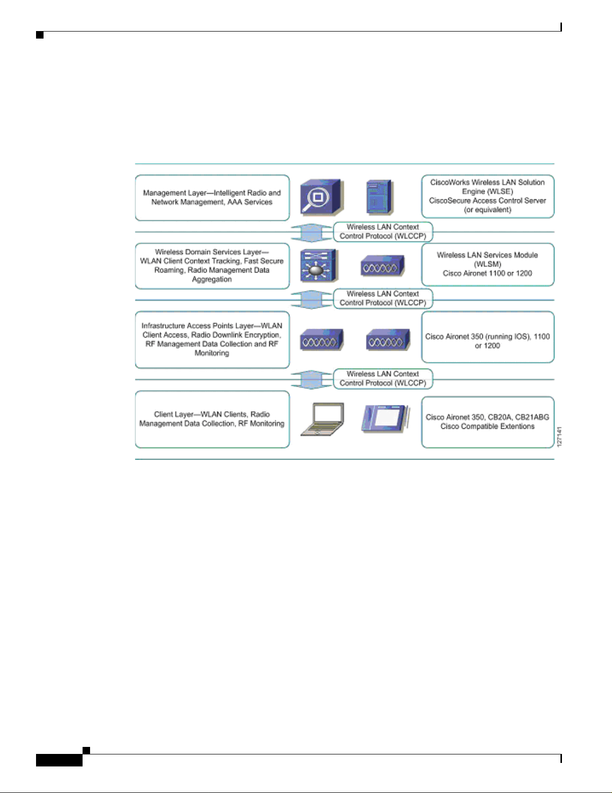
The Cisco SWAN framework can be vi su alized as a laye re d model. The Cis co S WAN framework layers
are:
• Management Layer
• Wireless Domain Services Layer
• Infrastructure Acc ess Point L ayer
• Wireless Client Layer
Cisco Structured Wire le ss-Aware Network (SW AN) Implem entation Guide
OL-6217-01
7
Page 8
Cisco SWAN Framewor k Overview
The Cisco SWAN framework introduces WLCCP to facilitate control messaging betwee n the framewo rk
components. Figure 1 illu strates th e concep tual mod el of the Cisco SWAN framework, including the
WLCCP messaging protocol . As shown in Figure 1, each layer is impl emented in specific Cisco
products.
Figure 1 Cisco SWAN Layers
Cisco Structured Wireless-Aware Network (SWAN) Implementation Guide
The management layer sup plies the pr ocessin g of RM data fr om the lower layers , controll ing and
managing the rad io c overage e nvironment. T his dat a i s also us ed fo r sec ur ing th e radi o coverag e
environment by detecting ro gue a cce ss poi nts an d wirele ss c lien ts. A uth en tica tion, A uthor izat ion, and
Accounting (AAA) services are also placed in the management layer.
The required management layer component is the CiscoWorks WLSE. An optional component is the
CiscoSecure ACS. Other products with func tionality eq uivalent to ACS may be used in Cisco SWA N.
The WDS layer provides critical services: WLAN client context awareness, fast secure roaming, and
aggregation of radio management data from the infrastructure access point and client layer. WDS is
implemented in supporting versions of Cisco IOS for the Cisco Air onet 1100 and 120 0 series acc ess
points and on the special Cisco IOS running on the wireless LAN service module for the Catalyst 6500
switch platform. The solution architecture dictates whether to use the WDS access point or the WLSM
implementation.
The infrastructure access point laye r facilitate s WLAN clie nt access to the wired-ne twork, radi o
downlink encryption, a nd ra dio ma nage ment data c oll ecti on , in clu ding on- goin g r adi o m onitor ing.
The client layer incl udes all wireless cl ient s. Advanced SWAN framework features take advantage of
client-side capabilities to allo w for radio measuremen t collection from th e WLAN clients and fast secure
roaming.
Cisco Structured Wireless-Aware Network (SWAN) Implementation Guide
8
OL-6217-01
Page 9
Cisco Structured Wireless-Aware Network (SWAN) Impl ementation Guide
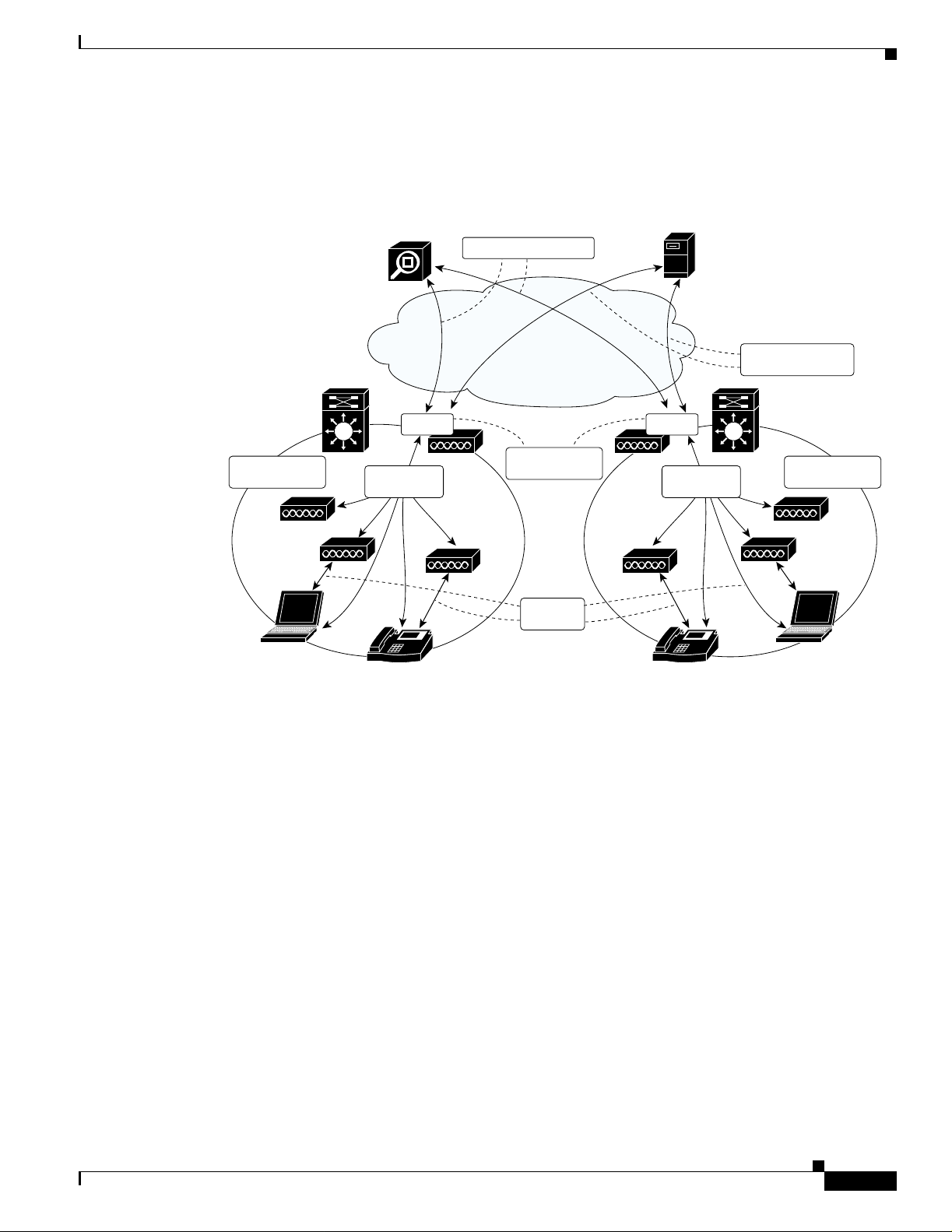
Figure 2 represents a logical, hierarchical view of the SWAN framework that clearly illustrates the
importance of the WDS layer.
Figure 2 Cisco SWAN Logical View
Cisco SWAN Framework Overview
WLAN control
domain
WLSE
WDS
WLCCP
messages
IP IP
WLCCP messages
802.1x
authenticator
Data
packets
ACS
WDS
WLCCP
messages
RADIUS control
domain
WLAN control
domain
127430
WDS are configured to r un on a sup portin g d evice—eithe r a Ci sco A iro net 1100 or 120 0 f or a Lay er 2
architectural solution or the WLSM for an switch-based, Layer 3 solution. In both cases, infrastructure
access points register with the WDS using special WLCCP messages.
Once registered, the infrastr ucture a ccess p oints forwa rd clie nt associa tion, a uthenti cation, and roa ming
information through the WDS via WLCCP MN registration messa ge s, allowing the WDS to co nt rol and
track wireless clients. If cli ent authe nticat ion is impleme nted via a ny 802.1x with EA P (such as Cisco
LEAP , EAP-F AST, PEAP, EAP-TLS, or EAP-TTLS), the WDS performs an additional important role by
acting as the 802.1x authenticat or for all wireless clie nts. In 802.1x authentication tr ansactions, the WDS
communicates directly with the RADIUS server. Any valid wireless client associated with an
infrastructure access point and registered with t he WDS.
A WDS, its registered in frast ruct u re a cce ss p oints , a nd regist ered c lient s make u p a WLA N co ntrol
domain. Wireless clients can seamlessly roam between access points within a WLAN control domain. A
WDS also collects radio manage ment data fro m the infr astruc ture access poi nts and, potential ly, the
MNs within the WLA N c on trol dom ain via sp eci al WLC C P rad io m anag eme nt ( WLC CP-RM )
messages. This data is aggregated by the WDS and pa ssed on to the WLSE in WLC CP-RM messa ges.
The WLSE uses this RM data to control and manage the radio coverage environment and to detect rogue
access points and clie nts.
Cisco SWAN offers two basic WL AN archi tectures : an arch itecture s upportin g a Lay er 2 WL AN contro l
domain and an architecture supporting a Layer 3 WLAN control domain. The Layer 2 architecture
leverag es access point-base d WDS. This architectu re is called the access point- based WDS solution. The
Layer 3 architecture leverages WLSM-based WDS and is called the switch-based WDS solution.
OL-6217-01
Cisco Structured Wire le ss-Aware Network (SW AN) Implem entation Guide
9
Page 10
Cisco SWAN Framewor k Overview
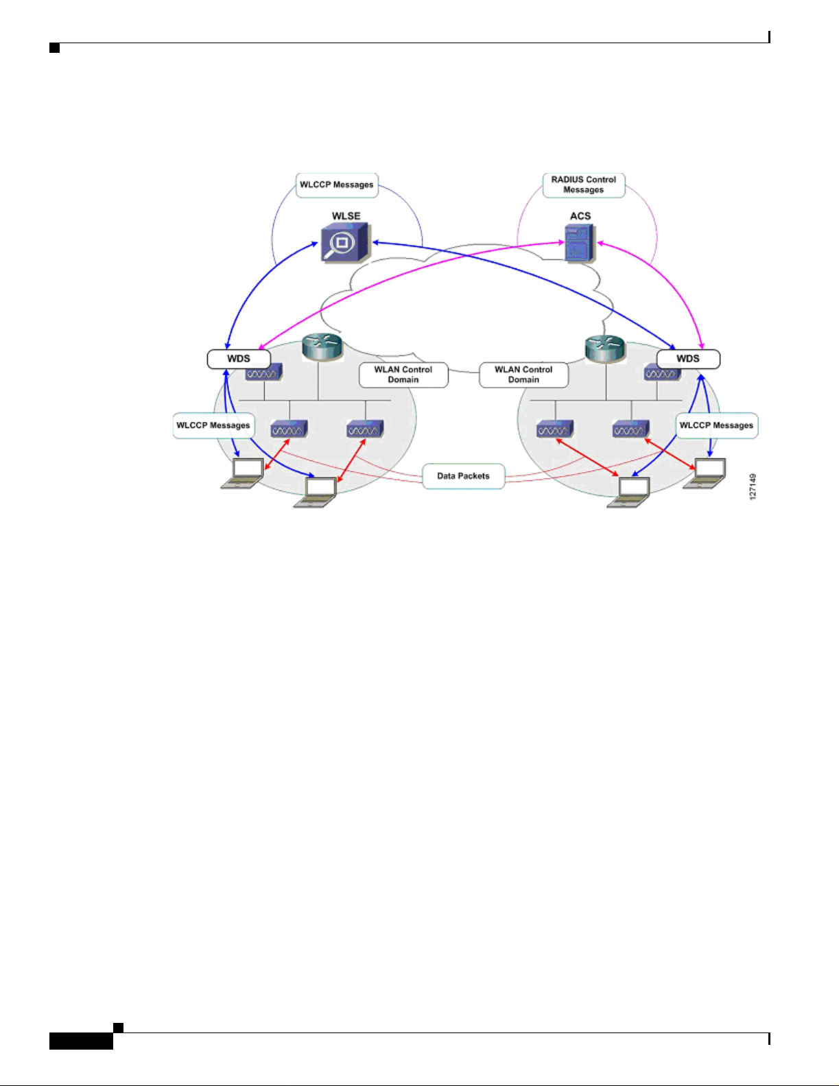
Figure 3 shows the access point-based WDS solution .
Figure 3 Access Point-Based WDS Solution
Cisco Structured Wireless-Aware Network (SWAN) Implementation Guide
In the access point-based WDS solution, infrastructure access points discover the WDS via special
WLCCP multicast messages. You must have an access point running WDS on each Layer 2 subnet . The
solution supports up to 30 infrastructure access points when the WDS-host access point is also serving
wireless clients and up to 60 infrastructure access points when the WDS-host access point is not serving
wireless clients. The access point-based WDS solution facilitates seamless MN roaming across a Layer
2 WLAN control context.
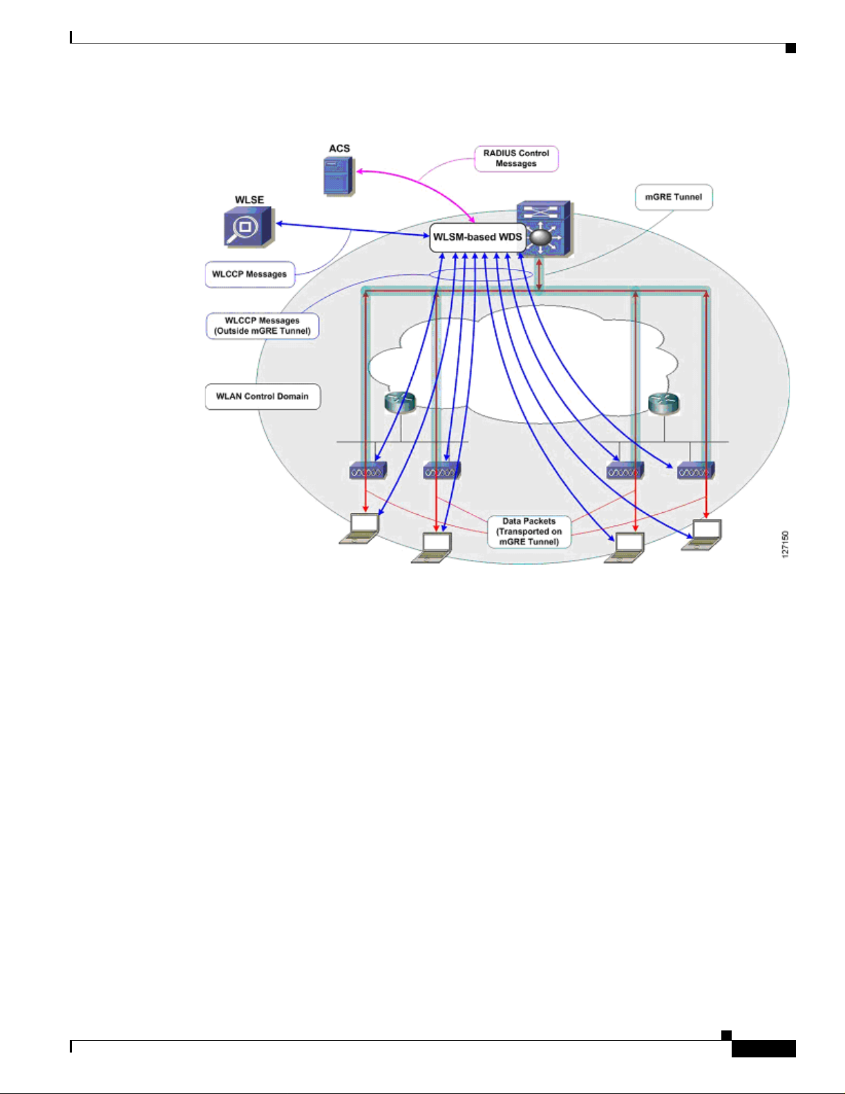
Figure 4 shows the switch-based WDS solution.
10
Cisco Structured Wireless-Aware Network (SWAN) Implementation Guide
OL-6217-01
Page 11
Cisco Structured Wireless-Aware Network (SWAN) Impl ementation Guide
Figure 4 Switch-Based WDS Solution
Cisco SWAN Framework Overview
In the switch-based WDS solution, mGRE tunnels are built from the Catalyst 6500 switch hosting the
WLSM where the WDS is running. Wireless client data is tun neled to the Cata ly st 6 500 switc h w here it
is forwarded appropriately. The mGRE tunnel legs are built wh en the infrastructure access poin ts register
with the WDS on the WLSM. Wireless client authentic ation and MN re gistratio n WLCCP messages are
forwarded to the WLSM for centralized processing. Unlike wireless client data traffic, WLCCP
messages are not forwarded on the mGRE tunnel legs. Rather, these messages traverse the ne twork like
standard IP packets. The switch -based WD S architectur e offers comple te control an d data plane
separation, which are essential elements to true network scalability. The switch-based WDS solution
facilitates seamless roaming across a Layer 3 WLAN control context and supports up to 300 registered
infrastructure acce ss poi nts an d 6000 M Ns p er WL SM.
CISCO SWAN Framework Components
The Cisco SWAN framework has software and hardware components.
The software components are:
• WDS
• WLCCP
The hardware components are:
• WDS-host devices
• Infrastructure a ccess points
OL-6217-01
Cisco Structured Wire le ss-Aware Network (SW AN) Implem entation Guide
11
Page 12

Cisco SWAN Framewor k Overview
• WLSE
• Cisco and Cisco compatible clients
Software Components
There are two softw are comp onents essen tial to the operat ion of th e Cisc o SWAN framew or k: W DS and
WLCCP.
WLCCP
WLCCP is a Cisco-defined co ntro l pr otoc ol t hat al lows contr ol c ommu ni cati on be twe en t he Cisco
SWAN components. WLCCP messages are used to auth en tic ate and re gi st e r Ci sco SWAN components,
constructing the Cisco SWAN control topology. The WLCCP messages are used in WLAN client
association and auth enticat ion, an d re-assoc iation a nd re-aut hentica tion duri ng client roaming .
WLCCP-RM is used to transfer radio measurement data between the Cisco SWAN components. A
technical discussion of WLCCP is beyond the scop e of this docume nt.
WDS
Cisco Structured Wireless-Aware Network (SWAN) Implementation Guide
WDS are a set o f IOS ser vice s th at de fine a WL AN co ntr ol do ma in. Within a WLA N co ntr ol do mai n,
all infrastructure access points register with the WDS. After registration, 802.1x WLAN client
authentications ar e forwarded th rough the WDS. Infrastr ucture access points registe r their asso ciated
WLAN clients with the WDS, so the WDS tracks all WLAN clients within the WLAN control domain.
WDS also collects radio manageme nt data fro m infrast ructure access points (and option ally mobi le
nodes), aggregates data, a nd forwards them to the CiscoWorks WLSE for intelligent proce ssing. WD S
can be impleme nted on an ac cess poin t or on the WLSM.
Hardware Components
The hardware required to impl ement th e Cisco SWAN framework includes WDS hosting devices,
infrastructure access points, and the CiscoWorks WLSE. Optional hardware components include WLAN
client devices: Cisco Airone t c lie nt ad apte rs a nd devices cert ified a s p art of t he C isco Com pa tibl e
Extensions program.
WDS-Host Devices
WDS can be hosted on an acc ess poi nt or on th e W LSM. W DS is su ppo rte d on the C is co Air onet 110 0
and 1200 series IOS-based access points for the access point-based WDS solution. WDS is supported on
the WLSM for the switch-based WDS solution.
Infrastructure Access Points
Infrastructure access points register with the WDS within the WLAN control domain. The Cisco Aironet
350, 1100, and 1200 series IO S-base d acce ss point s are supp orte d as infr as truct ure ac cess poin ts in the
access point-based W DS sol u tion. Cisc o Ai rone t 11 00 an d 1200 se rie s IOS- base d ac cess points ar e
supported as infrastructure access points in th e switch-ba sed WDS soluti on.
12
Cisco Structured Wireless-Aware Network (SWAN) Implementation Guide
OL-6217-01
Page 13

Cisco Structured Wireless-Aware Network (SWAN) Impl ementation Guide
Cisco Wireless LAN Solution Engine (CiscoWorks WLSE)
The Cisco Works WLSE is a mana geme nt too l th at pr ovid es c ompre hens i ve WLAN d e vic e mana geme nt,
including access point configurat ion, fault mana gement, a nd extensive reporting. The Cisco Works
WLSE also applies intelligence to radio management data gathered from the network. The intelligent
processing of data allows for adv anced RF management tools that con trol powe r and channel settings on
access points, detect interference, and detect, locate, and mitigate against WLAN intrusion sources.
WLAN Client Devices
Fast secure roaming using CCKM requires client device support for encryption key management. Cisco
Aironet client adapters and non-Cisco client adapters compliant to the Cisco Compatible Extensions
version 2 requirements support CCKM with Cisc o LEAP authen ticatio n. Cisco Airo net clie nt adap ters
and non-Cisco client adapters compliant with Cisco Compatible Extensions version 3 requirements can
use CCKM with EAP-FAST authentication. Other EAP types such as EAP-TLS and PEAP m ay be used
with CCKM with some third-party supplicants.
WLAN clients can also be used to gather radi o manage ment da ta with a radi o measure men t techniqu e
called the cl ien t wa lkab out an d d uri ng no rmal opera ti ons wi th a m easur e men t te ch nique cal led ra dio
monitoring. Cisco client adapters and client adapters compliant with the Cisco Compatible Extensions
version 2 requirements are us ed to gather ra dio mea surement data.
Implementing the Cisco SWAN Framework
Implementing the Cisco SWAN Framework
The phases of constructing t he Cisco SWAN framework are:
1. WDS activation
2. Infrastructure acc ess point authenti cation a nd registration
3. CiscoWorks WLSE authentication and registration
4. CiscoWorks WLSE device discovery and management
During the WDS activation phase, the WDS service becomes active on its host device. In the access
point-based WDS solution, the WDS advertises itself via WLCCP broadcast messages on the access
point management subnet .
In the infrastructure aut hentica tion and registra tion phase , infrastr ucture access points pre sent 802. 1x
credentials for authenticatio n to the WDS. Af ter authenticat ion, WLCCP reg istration requests a re issued
to the WDS. Cisco LEAP is currently the only supported authentication mechanism for infrastructure
access point authentication 802.1x or EAP types are supported for WLAN client authentication. In the
access point-based WDS solution, the WDS is discovered by infrastructure access points by the WLCCP
broadcast messages from the WDS. In the WLSM-based WDS solution, infrastructure access points
must be configured with the IP addr ess of the W LSM .
After the infrastructure access points are registered with the WDS, a WLCCP communication link is
established between the WD S and the CiscoWorks WLSE. The CiscoWorks WLSE IP address is
configured on the W DS-ho stin g d evice. Th e WDS d evice atte mp ts t o cont act th e Cisco Works WLSE
with WLCCP messages; this is how the CiscoWorks WLSE "discovers" the WDS device. After the
WLAN administrator manage s the WD S device within t he CiscoWorks WLSE, the CiscoWorks WLSE
presents credentials for auth en tic ation to the WDS. Af ter th e auth en tic atio n is c ompl ete d, th e WDS a nd
WLSE negotiate encryption keys to secure future WLCCP transactions.
OL-6217-01
Cisco Structured Wire le ss-Aware Network (SW AN) Implem entation Guide
13
Page 14

Implementing the Cisco SWAN Framework
When the encryption key negotiations are complete, the WDS reports all its registered infrastructure
access points to the Cisc oWorks WLSE for manage ment . A fte r the infr astr uctu re a c cess points ar e
managed on the CiscoWorks WLSE, the CiscoW orks WLSE interrogates the infrastructure access points
with SNMP to complete its internal inventory tables.
After the interrogation is complete, the Cisco SWAN framework is totally constructed and other
advanced features are used.
The following is a ch eck lis t for im plem entin g the C isc o SWAN framework for the acc ess
point-basednWDS solut ion:
• Configure the AAA server for infrastructure authentication
• Configure the AAA server for WLAN client authentication
• Prepare the CiscoWorks WLSE for managing the WLAN devices
• Configure the WDS access point(s)
• Configure the infrastructure access points
The following is a check list for implementing the Cisco SWAN framework for the switch-based WDS
solution:
• Configure the AAA server for infrastructure authentication
• Configure the AAA server for WLAN client authentication
Cisco Structured Wireless-Aware Network (SWAN) Implementation Guide
The following three subsections provide the details for each of these tasks. The first subsection focuses
on the tasks common to both the access po int-based W DS architecture and the switc h-based WDS
architecture. The sec ond subsection cov e rs in d etail t he tasks required wi th the access p oint-base d WDS
solution. The third subsection covers in detail the tasks required with the switch-based WDS solution.
Common Tas ks
The required tasks commo n to both th e switch- based and access po int-base d WDS solution s are:
Infrastructu re authe nt icatio n cur rent ly req uire s Ci sco LEA P. T y pica lly cu stom ers us e Ci scoS ecur e A C S
for LEAP authentication. Both infrastructure and client authentication can use AC S. In many customer
environments, AAA support for Cisco LEAP is not available for infrastructure authentication. As an
alternativ e for i nfras tructure authen tication, the lo cal RADIUS serv er embedded i n th e acce ss point IO S
is used. This document reviews the steps to configure the ACS and the local RADIUS servers on the
access point for infrastructure authentication. Other third-party AAA products support Cisco LEAP and
may be used for infrastr u cture authentication. Configuration of third-par ty AAA pr odu cts i s beyond the
scope of this do cu ment.
• Prepare the CiscoWorks WLSE for managing the WLAN devices
• Configure the WLSM
• Configure the infrastructure access points
• Configuring the AAA server to support infrastructure authentication
• Configuring the AAA server to support WLAN client authentication
• Preparing the CiscoWorks WLSE for managing WLAN devices
Configuring the CiscoSecure ACS Server for Infrastructure Authentication
To use the CiscoSecure ACS server for infrastructure authentication, you must complete the following
tasks:
Cisco Structured Wireless-Aware Network (SWAN) Implementation Guide
14
OL-6217-01
Page 15

Cisco Structured Wireless-Aware Network (SWAN) Impl ementation Guide
• Define each WDS-host as a network access server (NAS)
• Define credentials to be used by infrastructure access points for authentication
• To define each WDS-host as a NAS on the CiscoSecure ACS, follow these steps:
Step 1 Log into the CiscoSecure ACS server.
Step 2 Select Network Configuration from the menu on the left- hand side (se e Figu re 5 ).
Step 3 Under the AAA Clients section, select Add Entry (see Figure 5).
Figure 5 CiscoSecure ACS NAS Set up
Implementing the Cisco SWAN Framework
Step 4 Complete the form b y enterin g a) th e WDS-h ost de vi ce host n ame in t he AAA Client Hostname f i eld, b)
the WDS-host IP address in the AAA Client Address field, and (c) a RADIUS shared secret in the Key
field.
Note The key value is entered later on each WDS-host device.
Step 5 Select RADIUS (Cisco Aironet) in the Authenticate Using selection menu.
Step 6 Select the desired RADIUS loggi ng options.
Step 7 Click Submit or Submit + Restart (see Figure 6 ).
OL-6217-01
Cisco Structured Wire le ss-Aware Network (SW AN) Implem entation Guide
15
Page 16

Implementing the Cisco SWAN Framework
Figure 6 CiscoSecure ACS NAS Set up
Cisco Structured Wireless-Aware Network (SWAN) Implementation Guide
Step 8 Repeat Steps 2 through 7 for each WDS-host device.
Step 9 Restart the CiscoSecure ACS service by selecting Submit + Restart after completing the tasks through
Step 7. Or you can select System Configuration on the left-hand side menu, then Service Control, and
then Restart.
Adding Username and Password Credentials
Each infrastructure access point presents a username and password to the WDS when it authenticates.
These credenti al s m ust b e de fined on th e C iscoSe cure ACS and do not have to be un i que p er
infrastructure a cce ss poi nt. Most im ple me ntati ons u se a si ngle u ser name and pa ssword cr ed entia l p air
for all of the infrastructure access points. To add the username and password credentials into the
CiscoSecure ACS, follow these s teps:
Step 1 Log into the CiscoSecure ACS server.
Step 2 Select User Setup on the left-hand s ide me nu (see Figure 7).
Step 3 Enter a username in the User field, then select Add/Edit (see Figure 7).
16
Cisco Structured Wireless-Aware Network (SWAN) Implementation Guide
OL-6217-01
Page 17

Cisco Structured Wireless-Aware Network (SWAN) Impl ementation Guide
Figure 7 CiscoSecure ACS User Setup
Implementing the Cisco SWAN Framework
Step 4 Fill out the information relevant to the user, including the password, and then click Submit
(see Figure 8).
Figure 8 CiscoSecure ACS User Setup
Step 5
Repeat Steps 2 through 4 for each credentials pair you intend on using for infrastructure auth entication.
The CiscoSecure ACS setup for infrastructure access point authentication is now complete.
Configuring the Local RADIUS Server on the Access Point for Infrastructure Authentication
In environments where the AAA infrastructure does not support Cisco LEAP, the local RADIUS server
on an access point must be used for infrastructure authentication of access points. This section covers
the steps required to configure the local RADIUS server on an access point.
Cisco Structured Wire le ss-Aware Network (SW AN) Implem entation Guide
OL-6217-01
17
Page 18

Implementing the Cisco SWAN Framework
To configure the local RADIUS server on an access point, follow these steps:
Step 1 Access the access point co mm an d-li ne i nte rface and go in to configur ation m ode .
Step 2 Enter the following IOS command:
AAA-ap(config)# aaa new-model
Step 3 Enter the following IOS command:
AAA-ap(config)# radius-server local
You are now in the local RADIUS server configuration mode.
Step 4 Enter the following command for each WDS-host device while in the local RADIUS server
configuration mode:
AAA-ap(config-radsrv) nas <wds-host ip address> key <shared secret>
Step 5 Each infrastructure access point presents a username and password to the WDS when it authenticates.
These credent ia ls m ust b e de fined on t he l o cal RAD IUS server and do n ot have to b e uni qu e pe r
infrastructure a cce ss poi nt. Most im ple me ntati on s u se a si ngle u ser name and pa ssword cr ed en tial pai r
for all of the infrastructure access points. To add the username and password credentials into the local
RADIUS server, enter the following command while in local RADIUS configuration mode for each
username and password credential pair:
AAA-ap(config-radsrv) user <username> password <password>
Cisco Structured Wireless-Aware Network (SWAN) Implementation Guide
Step 6 Exit configuration m ode a nd save the con figurat ion to NV RAM .
Configuring the AAA Server to Support WLAN Client Authentication
The configuration steps required to configure client authentication depending on authentication
requirements for the WLAN clie nt. A discus sion of WLAN cli ent authent icati on and configurat ion is
beyond the scope of th is doc um en t. Con sul t pr odu ct do cu ment ation an d ot her re sourc es available f rom
http://www.cisco.com for the details of WLAN client authentication configuration.
Preparing the CiscoWorks WLSE for Managing WLAN Devices
The CiscoWorks WLSE uses three methods to communicate with WL AN devices in the network:
• WLCCP-Control transactions with the WDS-hosts
• SNMP-Interrogation o f all W LAN devices a nd som e configur ation tas ks
• Telnet or SSH-Configuration of access points via remote command-line interface
The CiscoWorks WLSE requires the following credentials to successfully communicate with WLAN
devices in the network:
• WLCCP credentials for initial authentication of the WLSE by the WDS-hosts
• SNMP read-only and read-write communities
• Telnet or SSH cred en tia l s
18
Cisco Structured Wireless-Aware Network (SWAN) Implementation Guide
OL-6217-01
Page 19

Cisco Structured Wireless-Aware Network (SWAN) Impl ementation Guide
To configure the necessary credentials on the CiscoWorks WLSE follow these steps:
Step 1 Log into the Ci scoWorks WLSE.
Step 2 Navigate to Devices > Discover. Select Device Credentials on the left-hand side table of contents (see
Figure 9).
Step 3 Select SNMP Communities on the left-hand side table of contents (see Figur e 9).
Step 4 In the form, enter the appropriate SNMP credentials. Consult the CiscoWorks WLSE online-help for
details on SNMP credential entry syntax.
Figure 9 CiscoWorks WLSE SNMP Community Entry Screen
Implementing the Cisco SWAN Framework
OL-6217-01
Step 5
Select Device Credentials > Telnet/SSH User/Password from the table of contents on the left-hand
side (see Figure 1 0).
Step 6 Enter the appropriate Telnet or SSH credentials for logging in to th e manage d access poin ts for
configuration (see Figu re 10 ). Con sult the Ci scoWorks WLSE online hel p for de tail s o n Telnet or SSH
credentials ent r y sy nt ax .
Cisco Structured Wire le ss-Aware Network (SW AN) Implem entation Guide
19
Page 20

Implementing the Cisco SWAN Framework
Figure 10 CiscoWorks WLSE Telnet/SSH Credentials Entry
Cisco Structured Wireless-Aware Network (SWAN) Implementation Guide
Step 7 Select Device Credentials > WLCCP Credentials from the table of contents on the left-hand side (see
Figure 11).
Step 8 Enter the appropriate WLCCP credentials for logging in to the managed access points for configuration
(see Figure 11). Consult the CiscoWorks WLSE online help for details on WLCCP credentials entry
syntax.
Figure 11 CiscoWorks WLSE WLCCP Credentials Entry
20
The required e lem en ts of t he initi al Cisc oWorks WLSE setup are now comp let e. Some a dd ition al,
optional tasks are recommended:
• Configuring the CiscoWorks WLSE advanced discovery options
• Configuring the CiscoWorks WLSE automatic configuration option s
Cisco Structured Wireless-Aware Network (SWAN) Implementation Guide
OL-6217-01
Page 21

Cisco Structured Wireless-Aware Network (SWAN) Impl ementation Guide
Configuring Advanced Di scovery Options
Advanced d iscovery o ptions include enabling de vice rev erse-DNS name res olution, dev ice auto-manage,
and auto-manage filtering by MAC address. The format for device name within the WLSE can also be
configured. Advanced discovery parameters are configured through CiscoWorks WLSE interface found
in De vi ces > Disco ver under the Discover > Advanced Op tions in the tabl e of conten ts on the left-han d
side. Consult the CiscoWorks WLSE online help for deta ils on using th ese a dvanced discovery opt ion s.
The most useful of the se op t ions ma y be t he a uto- ma nage o pti on. By de fau lt, w he n devices ar e
"discover ed " by the CiscoWorks WLSE, they are placed into a New state until the WLAN administrator
Manages the devices in the CiscoW orks WLSE. While in the New state, the devices are not interrogated
by the WLSE and cannot be configured. The default disc overy behavior can be overridden so that the
CiscoWorks WLSE automatically manages the devices instead of placing them into the New state.
When the auto-manage feature is used, WDS devices are automatically managed. The CiscoWorks
WLSE and WDS negotiate encryption keys, and the WDS automatically reports all of its registered
infrastructure access poi nts to the Ci sco Works WLSE. The CiscoWorks WLSE automatically manage s
these infrastructure devices too.
Using Automatic Configuratio n
Implementing the Cisco SWAN Framework
Access points can be automatically configured by using the automatic configuration options in the
CiscoW orks WLSE. As access points are automatically managed, a configuration template is applied to
devices. The basic ste ps to us e the au toma tic c onfigurati on fea ture s are:
Step 1 Create a basic configuration template(s) through the Configure>Templates interface on the CiscoWorks
WLSE.
Step 2 Define the template(s) as an auto- man ag e tem plate and spe cif y filtering criteria throu gh the Configure
> Auto Update interface on the CiscoWorks WLSE.
A detailed discussi on on usi ng t he a uto-c on figuration fe atur es of t he Ci scoWorks WLSE is beyond the
scope of this do cume nt. Con sul t the C is coWorks WLSE online help fo r m or e de tail s o n us ing the se
features.
Access Point-Based WDS Solution Configuration
This section explains the configuration tasks required to configure the access point-based WDS solution
such as the following:
• Configuring the WDS access point
• Configuring the infrastructure access point
• Managing the access points with the Cisco Works WLSE
• Validating the setup
Configuring the WDS Access Point
This section explains t he configuration tasks required to set up a n access point to operate a s a WDS-host.
Note This solu tio n req uire s on e WDS acc ess po in t per I P sub net .
OL-6217-01
Cisco Structured Wire le ss-Aware Network (SW AN) Implem entation Guide
21
Page 22

Implementing the Cisco SWAN Framework
These are the bas ic configur ation tasks:
• Entering a host name for the access point
• Defining SNMP communitie s
• Defining Telnet or SSH parameters
• Defining AAA parameters for infrastructure authentication
• Defining AAA parameters for WLAN client authentication
• Defining WLCCP cr ed en tial s
• Enabling W DS s e rvic es
• Defining the CiscoWorks WLSE
Follow these steps to complete the tasks:
Step 1 Log into the access point command-line interface and enter the configuration mode.
Step 2 Enter a host name for the access point:
wds-ap(config)#hostname <hostname>
Cisco Structured Wireless-Aware Network (SWAN) Implementation Guide
Step 3 Enter the following commands to define the SNMP communities:
wds-ap(config)#snmp-server view iso iso included
wds-ap(config)#snmp-server community <read-only community> view iso RO
wds-ap(config)#snmp-server community <read-write community> view iso RW
Step 4 Enter the f ol l owing to d efin e Telnet or SS H use r s :
wds-ap(config)# username <username> password <password>
Step 5 Enter the following to enable SSH (optional step):
wds-ap(config)# ip domain-name <ip domain-name>
wds-ap(config)# crypto key generate rsa general-keys modulus <key size>
Step 6 Enter the following to turn off Telnet (optional step), define an access control list, and apply it to the
T elnet lines. Obvio usly, several access control list de finition s can acco mplish this task, bu t the follo wing
is an example:
wds-ap(config)# access-list <access-list number> permit tcp any any neq telnet
wds-ap(config)# line 0 16
wds-ap(config-line)# access-class <access-list number>
Step 7 Enter the following to define AAA parameters for infrastructure authentication:
wds-ap(config)# aaa new-model
wds-ap(config)# radius-server host <ip address> auth-port <auth-port> acct-port
<acct-port> key <shared secret>
wds-ap(config)# aaa group server radius wlccp_infra
wds-ap(config-sg-radius)# server <ip address> auth-port <1812> acct-port <1813>
wds-ap(config)# aaa authentication login infrastructure-authentication group radius
wds-ap(config)# aaa authentication login client-authentication group radius
22
If using a local RADIUS server on an access point, the authentication port is always 1812, and the
accounting port i s a lways 1 813.
Cisco Structured Wireless-Aware Network (SWAN) Implementation Guide
OL-6217-01
Page 23

Cisco Structured Wireless-Aware Network (SWAN) Impl ementation Guide
Step 8 Enter the following to define AAA parameters for client authentication:
wds-ap(config)# radius-server host <ip address> auth-port <auth-port> acct-port
<acct-port> key <shared secret>
wds-ap(config)# aaa group server radius client_group
wds-ap(config-sg-radius)# server <ip address> auth-port <1812> acct-port <1813>
wds-ap(config)# aaa authentication login client-group group client_group
wds-ap(config)# wlccp authentication-server client any client-group
This step is very impo rt ant . Af ter the Cisc o SWAN topology is established, al l 80 2.1x cli ent
authentications ar e forwa rded th ro ugh t he W DS. I f th e cli ent aut hen tic ati on gr oup(s) i s n ot p rop er ly
configured, WLAN clients are denied network access.
RADIUS servers redef ined w ith the f irst command a re using the sa me AAA serv er for in frastructur e and
client authentication.
Step 9 Enter the following commands to enable WDS service on the access point:
wds-ap(config)# wlccp wds priority <priority number>
Valid priority values are between 1 and 255 inclusive. The WDS priority field is used to elect a WDS
master access point when m ore than one acce ss po int on th e subn et i s conf i gured . When mul tiple ac cess
points are configured to run WDS, an election is held. The access point with the highest WDS priority
value becomes the active WDS and the other access point(s) go into WDS-standby mode. If two or more
access points hav e the same WDS priority , the tie-break er is the high est value F astEtherne t MA C address
of the competing access points. The active WDS should always be configured with priority value 255.
Implementing the Cisco SWAN Framework
Step 10 Enter the following command to define the WLCCP credentials for the access point:
wds-ap(config)# wlccp ap username <wlccp_username> password <password>
The WDS-host access point is now registered with the WDS service and serves as an infrastructure
access point.
Step 11 Define the CiscoWorks WLSE on the WDS access point:
wds-ap(config)# wlccp wnm ip address <wlse ip address>
Subsequent to these steps, cus tomers ca n configure ad ditiona l paramet ers like VLAN s, SSIDs, and
encryption settings. Custom er s may cho ose to use t he Cisc oWorks WLSE to do these configurations in
bulk after the CiscoWorks WLSE has discovered the WDS-ho st a nd th e infra struc ture ac cess points.
Configuring the Infrastructure Access Point
Configuring the infrastruc ture access point is much simpler than conf iguring th e WDS access point. The
necessary tasks are as fo llows:
• Define SNMP communities
• Enter a host name for the access point
• Define Telnet/SSH parameters
• Define WLCCP credentials
Follow these steps to complete the tasks:
OL-6217-01
Step 1 Log into the ac cess poi nt co mm an d-line in te rface and e nte r c on figurati on mode.
Cisco Structured Wire le ss-Aware Network (SW AN) Implem entation Guide
23
Page 24

Implementing the Cisco SWAN Framework
Step 2 Enter the following commands to define the SNMP communities:
infra-ap(config)#snmp-server view iso iso included
infra-ap(config)#snmp-server community <read-only community> view iso RO
infra-ap(config)#snmp-server community <read-write community> view iso RW
Step 3 Enter a host name for the access point:
infra-ap(config)#hostname <hostname>
Step 4 Enter the f ol l owing to d efin e Telnet or SS H use r s :
infra-ap(config)# username <username> password <password>
Step 5 Enter the following to enable SSH (optional step):
infra-ap(config)# ip domain-name <ip domain-name>
infra-ap(config)# crypto key generate rsa general-keys modulus <key size>
Step 6 Enter the following to turn off Telnet (optional step), define an access control list, and apply it to the
T elnet lines. Obvio usly, several access control list de finition s can acco mplish this task, bu t the follo wing
is an example:
infra-ap(config)# access-list <access-list number> permit tcp any any neq telnet
infra-ap(config)# line 0 16
infra-ap(config-line)# access-class <access-list number>
Cisco Structured Wireless-Aware Network (SWAN) Implementation Guide
Step 7 Enter the following command to define the WLCCP credentials for the access point:
infra-ap(config)# wlccp ap username <wlccp_username> password <password>
Subsequent to these steps, cus tomers ca n configure ad ditiona l paramet ers like VLAN s, SSIDs, and
encryption settings. Custom er s may cho ose to use t he Cisc oWorks WLSE to do these configurations in
bulk after the CiscoWorks WLSE has discovered the WDS-ho st a nd th e infra struc ture ac cess points.
Managing the Access Points with the CiscoWorks WLSE
When WDS is acti v e on i ts host( s) and all inf rastruct ure acc ess poi nts are re gister ed with the appr opriate
WDS, the access poi nts m ust be di scovered and m an aged on t he C isco Works WLSE. The proced ure is
as follows:
Step 1 Log into the Ci scoWorks WLSE.
Step 2 Navigate to Devices > Discover. Sele ct Managed/Unmanaged in the table of contents on the left-h an d
side.
Step 3 The WDS device(s) are listed in the New folder portion on the right-hand side action pane. Select the
WDS device(s) and then Manage. The negotiation of security between the WDS and CiscoWorks WLSE
begins. After the encryption keys are negotiated, the WD S is interrogat ed. The WD S device reports its
registered access points to the CiscoWorks WLSE. The CiscoWorks WLSE then interrogates the
registered access p oint s. Th is pr oc es s may take 5 to 10 minu tes depen di ng on t he n um ber o f acc ess
points.
24
The infrastructure ac cess points shou ld now be managed in the CiscoWorks WLSE following the
instructions in Steps 2 and 3.
Note This proc edure is un nece ssary if the ad vanced discovery aut o-man age opti on was configure d prior to
WDS-host discovery.
Cisco Structured Wireless-Aware Network (SWAN) Implementation Guide
OL-6217-01
Page 25

Cisco Structured Wireless-Aware Network (SWAN) Impl ementation Guide
Validating the Configuration
The IOS command line on the WDS host can be used to v alidate the conf igurations . T o v alidate the WDS
configuration, enter this command:
show wlccp wds ap
All of the registered access points and infrastructure access points are listed. For example:
wds-ap# show wlccp wds ap
MAC-ADDR IP-ADDR STATE LIFETIME
000d.28f2.33ea 10.1.12.19 REGISTERED 171
000d.28f2.3426 10.1.12.23 REGISTERED 173
000d.28f2.3436 10.1.12.22 REGISTERED 183
000c.8576.326e 10.1.12.18 REGISTERED 497
To validate that the CiscoWorks WLSE is correctly registered, enter this command:
show wlccp wnm status
The CiscoWorks WLSE IP address is listed, and “Security Keys Setup" appears in the Status field.
wds-ap# show wlccp wnm status
WNM IP Address : 172.20.98.221 Status : SECURITY KEYS SETUP
Implementing the Cisco SWAN Framework
Switch-Based WDS Solution Configuration
In this section, the conf iguration tasks re quired to conf igure the switch -based WDS solution are c overed.
These tasks include the following:
• Configuring the Catalyst 6500 Supervisor 720
• Configuring the WDS on the WLSM module
• Configuring the infrastructure access point
• Managing the access points with the Cisco Works WLSE
• Validating the setup
Configuring the Catalyst 6500 Supervisor 720
This section is not an extensive discussion on configuring the Ca talyst Superv isor 720 to supp ort the
Cisco SWAN sw itch based WDS solution. This sec tion covers only the ba sics of configurati on. More
extensive discussions are available at http://www.cisco.com/go/swan.
The required c onfigura tion t asks fo r th e Supe rvis or 720 are as fol lows:
• Configure a VLAN between the super visor and WLSM
• Configure the multi-point GRE tunnel interfaces
• Configure SNMP communities
Follow these steps to complete the tasks:
OL-6217-01
Step 1 Gain access to the supervisor command-line interface and enter configuration mode.
Cisco Structured Wire le ss-Aware Network (SW AN) Implem entation Guide
25
Page 26

Implementing the Cisco SWAN Framework
Step 2 Create the VLAN between the supervisor and WLSM:
sup-720(config)# interface Vlan <vlan number>
sup-720(config-int)# ip address <ip address> <network mask>
sup-720(config-int)# exit
Step 3 Define the VLAN created in step 2 as the VLAN between the supervisor and WLSM.
sup-720(config)# wlan module <wlsm module number> allowed-vlan <vlan number>
The WLSM module number correspo nds to the sl ot in which the WL SM resides. The vlan number is the
number of the VLAN crea ted in Step 2.
Step 4 Create a loopback interface to serve as a tunnel source.
sup-720(config)# interface Loopback <Loopback number>
sup-720(config-int)# ip address <ip address> <network mask>
sup-720(config-int)# exit
Step 5 Define the multi-point GRE tunnel interface.
sup-720(config)# interface Tunnel <Tunnel Number>
sup-720(config-int)# ip address <ip address> <network mask>
sup-720(config-int)# ip helper-address <dhcp server address>
sup-720(config-int)# ip dhcp snooping packets
sup-720(config-int)# tunnel source Loopback <Loopback interface number>
sup-720(config-int)# tunnel mode gre multipoint
sup-720(config-int)# mobility network-id <mobility group number>
sup-720(config-int)# mobility trust
sup-720(config-int)# mobility broadcast
sup-720(config-int)# exit
Cisco Structured Wireless-Aware Network (SWAN) Implementation Guide
The tunnel source refers to the interface created in Step 4. The <mobility group number> defines the
mobility group. The same identifier is used on the infrastructure access points. The mobility trust
command is an optional command allowing WLAN clients with static IP addresses. Without the mobility
trust command, these clients are denied access to the network. The mobility bro adcast command is an
optional command that instructs the supervisor to forward broadcast traffic from one multi-point GRE
tunnel leg onto the other tunnel l egs. Without this command , broad cast traffic is not forwarde d.
Step 6 Repeat Steps 4 and 5 for each desired mobility group.
Step 7 Define the SNMP communities as follows:
sup-720(config)# snmp-server community <snmp read-only community name> RO
sup-720(config)# snmp-server community <snmp read-write community> RW
Unlike the SNMP configurat ions on the WLSM and a cces s po ints, an SNM P vi ew definition is not
required by the supe rviso r.
Configuring the WDS on the WLSM
In this section, the configuration steps required to set up the WLSM and WDS on the WLSM are
provided. Configuring the WDS on th e WLSM is very similar to conf iguring WDS on the acc ess points,
with a few variations. The necessary tasks are as follows:
• Define the WLAN VLAN to the supervisor
• Define SNMP communities
• Define a host name for the WLSM
26
• Define AAA parameters for infrastructure authentication
Cisco Structured Wireless-Aware Network (SWAN) Implementation Guide
OL-6217-01
Page 27

Cisco Structured Wireless-Aware Network (SWAN) Impl ementation Guide
• Define AAA parameters for WLAN client authentication
• Define the CiscoWorks WLSE
Follow these steps to complete the tasks:
Step 1 Access the WLSM command-line interface.
Step 2 Define the WLAN VLAN:
wlsm(config)wlan vlan <VLAN number>
wlsm(config-wlan)ipaddr <ip address> <network mask>
wlsm(config-wlan)gateway <gateway ip address>
wlsm(config-wlan)admin
wlsm(config-wlan)exit
The VLAN number corresponds to the VLAN number created in Step 2 of the supervisor configuration.
The gateway IP add ress is configured as the IP address of this VLAN interface on the supervisor. The
admin command instructs the WLSM to use this VLAN for controlling messaging to and from the
supervisor.
Step 3 Define a default route to the supervisor:
wlsm(config)ip route 0.0.0.0 0.0.0.0 <gateway ip address>
The <gateway IP add ress> is the address of the WLAN VLAN interface created in Step 2 of the
supervisor configuration.
Implementing the Cisco SWAN Framework
Step 4 Define the SNMP communities:
wlsm(config)#snmp-server view iso iso included
wlsm(config)#snmp-server community <read-only community> view iso RO
wlsm(config)#snmp-server community <read-write community> view iso RW
Step 5 Enter a host name for the WLSM :
wlsm(config)#hostname <hostname>
Step 6 Define the AAA parameters fo r infrast ructu re authe nticat ion:
wlsm(config)# aaa new-model
wlsm(config)# radius-server host <ip address> auth-port <auth-port> acct-port <acct-port>
key <shared secret>
wlsm(config)# aaa group server radius wlccp_infra
wlsm(config-sg-radius)# server <ip address> auth-port <1812> acct-port <1813>
wlsm(config)# aaa authentication login wlccp-infra group wlccp_infra
wlsm(config)# wlccp authentication-server infrastructure wlccp-infra
The RADIUS server IP address should be that of the AAA server for infrastru cture authentication. If this
is the local RADIUS server on an access point, the authentication port is always 1812, and the accounting
port is always 1813.
Step 7 Define the AAA parameters for client authentication:
wlsm(config)# radius-server host <ip address> auth-port <auth-port> acct-port <acct-port>
key <shared secret>
wlsm(config)# aaa group server radius client_group
wlsm(config-sg-radius)# server <ip address> auth-port <1812> acct-port <1813>
wlsm(config)# aaa authentication login client-group group client_group
wlsm(config)# wlccp authentication-server client any client-group
OL-6217-01
Cisco Structured Wire le ss-Aware Network (SW AN) Implem entation Guide
27
Page 28

Implementing the Cisco SWAN Framework
This step is very impo rt ant . Af ter the Cisc o SWAN topology is established, al l 80 2.1x cli ent
authentications ar e forwa rded thro ugh th e WD S. I f the cl ie nt a uthe nti cat ion gr oup (s) i s n ot p rop er ly
configured, WLAN clients are denied access to the network.
RADIUS servers are not redefined with the first command if you are using the same AAA server for
infrastr uc tu re a n d c lie n t au th enticatio n .
Step 8 Define the CiscoWorks WLSE:
wlsm(config)# wlccp wnm ip address <wlse ip address>
Configuring the Infrastructure Access Points
Configuring the infrastructure access points to register with the WDS on the WLSM is similar to
configuring infrastru ctu re a cce ss p oints wh en the W DS i s ho sted on the ac ce ss poi nt. Th e n ece ssar y
tasks are as follows:
• Define SNMP communities
• Enter a host name for the access point
• Define Telnet or SSH parameters
Cisco Structured Wireless-Aware Network (SWAN) Implementation Guide
• Define WLCCP credentials
• Define the WLSM as the WDS
Follow these steps to complete the tasks:
Step 1 Log into the ac cess poi nt co mm an d-line in te rface and e nte r c on figurati on mode.
Step 2 Enter the following commands to define the SNMP communities:
infra-ap(config)#snmp-server view iso iso included
infra-ap(config)#snmp-server community <read-only community> view iso RO
infra-ap(config)#snmp-server community <read-write community> view iso RW
Step 3 Enter a host name for the access point:
infra-ap(config)#hostname <hostname>
Step 4 Enter the f ol l owing to d efin e Telnet or SS H use r s :
infra-ap(config)# username <username> password <password>
Step 5 Enter the following to enable SSH (optional step):
infra-ap(config)# ip domain-name <ip domain-name>
infra-ap(config)# crypto key generate rsa general-keys modulus <key size>
Step 6 Enter the following commands to turn off Telnet (optional step), define an access control list, and apply
it to the Telnet lines. Obviously, many access control list definitions can accomplish this task, but the
following is an example:
infra-ap(config)# access-list <access-list number> permit tcp any any neq telnet
infra-ap(config)# line 0 16
infra-ap(config-line)# access-class <access-list number>
28
Step 7 Enter the following command to define the WLCCP credentials for the access point:
infra-ap(config)# wlccp ap username <wlccp_username> password <password>
Step 8 Enter the following to direct the infrastructure access point to the WDS on the WLSM:
infra-ap(config)# wlccp ap wds ip address <wlsm ip address>
Cisco Structured Wireless-Aware Network (SWAN) Implementation Guide
OL-6217-01
Page 29

Cisco Structured Wireless-Aware Network (SWAN) Impl ementation Guide
Subsequent to these steps, cus tomers ca n configure ad ditiona l paramet ers like VLAN s, SSIDs, and
encryption settings. Custom er s may cho ose to use t he Cisc oWorks WLSE to do these configurations in
bulk after the CiscoWorks WLSE has discovered the WDS-ho st a nd th e infra struc ture ac cess points.
Managing the WLSM and Access Points with the CiscoWorks WLSE
When WLSM is active and all of the infrastructure access points are registered, the access points must
be discovered and managed o n th e Cisco Works WLSE. Follow these steps to ma nage the W LSM:
Step 1 Log into the Ci scoWorks WLSE.
Step 2 Navigate to Devices > Discover. Select Managed/Unmanaged in the table of contents on the left-hand
side.
Step 3 The WLSM WDS device displays in the New folder on the right-han d side act ion pane .
Step 4 Select the WLSM and then Manage. The negotiation of secu rit y betw een the W DS a nd Ci scoWorks
WLSE begins. After the encrypt ion keys are negotiated, the WDS is inter rogated. The WDS device
reports its registered access points to the CiscoWorks WLSE. The CiscoWorks WLSE then interrogates
the registered access points. This proc ess may take 5 t o 10 minute s de pending on t he num ber of acce ss
points.
The infrastructure access points are managed in the CiscoWorks WLSE by completing Steps 2 through 4.
Implementing the Cisco SWAN Framework
Note This proc edure is un nece ssary if the ad vanced discovery aut o-man age opti on was configure d prior to
WDS-host discovery.
Validating the Setup
The IOS command line on the WLSM is used to validate the configurations. To validate the WDS
configuration, enter this command:
show wlccp wds ap
All registered access points and infrastructure access points are listed.
wlsm# show wlccp wds ap
MAC-ADDR IP-ADDR STATE LIFETIME
000d.28f2.33ea 10.1.12.19 REGISTERED 171
000d.28f2.3426 10.1.12.23 REGISTERED 173
000d.28f2.3436 10.1.12.22 REGISTERED 183
000c.8576.326e 10.1.12.18 REGISTERED 497
To validate that the CiscoWorks WLSE is correctly registered, enter this command:
show wlccp wnm status
The CiscoWorks WLSE IP address is lis ted a nd Secur ity Keys Setup ap pe ars i n t he st at us field.
wlsm# show wlccp wnm status
WNM IP Address : 172.20.98.221 Status : SECURITY KEYS SETUP
OL-6217-01
Cisco Structured Wire le ss-Aware Network (SW AN) Implem entation Guide
29
Page 30

Implementing the Cisco SWAN Framework
You shou ld al so n avigate to t he Ca ta lyst 65 00 Superv is or co mm an d-li ne in terfa ce a nd validate th at t he
control communications between the WLSM and super visor a re co rre ctly w ork ing. E nt er th is co mman d
to take a general look at the sta tus:
show mobility status
Enter this command to show the slot location of the WLSM, the LCP status, tunnel information,
registered access points, registered mobile nodes, and important information about the tunnels:
sup720# show mobility status
WLAN Module is located in Slot: 1 (HSRP State: Not Applicable)
LCP Communication status: up
MAC address used for Proxy ARP: 0008.2034.7400
Number of Wireless Tunnels: 4
Number of Access Points: 1
Number of Mobile Nodes: 3
Wireless Tunnel Bindings:
Src IP Address Wireless Network-ID Trusted Broadcast
--------------- ------------------- ------- ---------
10.100.1.1 1 No Yes
10.100.2.1 2 Yes Yes
10.100.3.1 3 Yes Yes
10.100.4.1 4 Yes No
Cisco Structured Wireless-Aware Network (SWAN) Implementation Guide
Enter the following command to show informat ion about t he registered ac cess points:
show mobility ap
The IP addresse s, MAC addresses , and ap propri ate ne twork i denti fiers for th e register ed acc ess p oints
are shown:
sup720# show mobility ap
AP IP Address AP Mac Address Wireless Network-ID
--------------- ------------- - -- ----- --- -- --- ----
10.200.20.49 000b.fcfb.e836 4
Enter the following command to show information a bout register ed client mobile node s:
show mobility mn
The MN MAC add ress, MN IP addr ess, the IP ad dress of the MN's current acce ss point , and the net work
identifier of the MN is shown:
sup720# show mobility mn
MN Mac Address MN IP Address AP IP Address Wireless Network-ID
-------------- --------------- --------------- -------------------
0004.e28b.2c28 172.16.4.3 10.200.20.49 4
00d0.59c8.60e1 172.16.4.2 10.200.20.49 4
Enter the following command to show information about a specific mobility group.
show mobility network <network-id>
30
Cisco Structured Wireless-Aware Network (SWAN) Implementation Guide
OL-6217-01
Page 31

Cisco Structured Wireless-Aware Network (SWAN) Impl ementation Guide
The tunnel source, ne twork attri butes and state, registered acc ess points with tunne l end-poi nts for the
mobility group, and the registered mobile in the mobility group are shown:
sup720# show mobility network 4
Wireless Network ID: 4
Wireless Tunnel Source IP Address: 10.100.4.1
Wireless Network Attributes: Trusted
Wireless Network State: Up
Registered Access Point on Wireless Network 4:
AP IP Address AP Mac Address Wireless Network-ID
--------------- ------------------ -------------------
10.200.20.49 000b.fcfb.e836 4
Registered Mobile Nodes on Wireless Network 4:
MN Mac Address MN IP Address AP IP Address Wireless Network-ID
------------------ ----------------- ---------------- ----------------------
0004.e28b.2c28 172.16.4.3 10.200.20.49 4
00d0.59c8.60e1 172.16.4.2 10.200.20.49 4
Fast Secure Roaming with CCKM
Implementing the Cisco SWAN Framework
WLAN clients by definition are mobile. The WLAN industry has standardized the IEEE 802.1X with
EAP authentication for secure authorization and access to the WLAN. The inherent mobility of WLAN
clients creates significant challen ges in mana ging W LAN client authen ticat ions and enc rypti on keys
within the 802. 1X/EA P au then tic atio n f ra mework. Signi ficant pro blem s a rise f rom h an dli ng the
re-authentication of WLAN clients (as they move associations from one access point to another) and in
generating dynamic enc r yption keys for t hes e c lients. As cl ie nts r oam, r e-au thentic atio n a nd dy na mic
key generation are fast so that service disruption does not occur, and WLAN client and network integrity
and security are maintained.
Cisco has addressed the challenge of fast secure roaming within the Cisco SWAN framew ork by def ining
a key management scheme called CCKM. CCK M works when an 80 2.1X wi th EAP authent ication
scheme is in place, as long as the client device supports it.
The basic concept is that the WDS maintains context awareness of all MNs within its WLAN control
domain. The WDS proxies initial authentication transactions with the RADIUS server and manages a
master set of en cr ypti on keys. T he M N ge ne rat es th e sa me set of e ncryp tio n keys ind epend en tly aft er
initial authentication. When th e MN r o ams to a new access point within t he WLAN co ntrol d o main, the
WDS can vouch for the M N on the n ew access poin t a nd gene rate new en crypt ion keys fo r th e acc ess
point to use. The M N i nde pe ndent ly gener a tes the same new enc ry ption keys wh en i t r oam s. The M N
can thus roam seamlessly within th e WLAN co ntrol do main. CCKM includes pro tect ions against
common attack vectors like spo ofing, replay attack s, or man- in-the-m iddle attacks.
This section focuses on what needs to be configured to use CCKM. The details and theory of operations
for CCKM are beyond the sco pe of this do cume nt. The co nfigurati on task s require d to use CCKM are
as follows:
• Configure the WDS for 802.1X client authentication
OL-6217-01
• Configure the access point to use CCKM
• Configure the WLAN client device if necessa ry
The details of conf iguring the WDS f or client au thentication are cov ered in the “Impleme nting the Cisco
SWAN Fr amework” sect ion o n pa ge 13," specifically in the sections on configuring the WDS-host
devices.
Cisco Structured Wire le ss-Aware Network (SW AN) Implem entation Guide
31
Page 32

Cisco Structured Wireless-Aware Network (SWAN) Implementation Guide
Implementing the Cisco SWAN Framework
When Not Using Multiple Authentication Types, Encryption Types, or VLANs
If you are not using multiple authentication or encryption types or VLANs on the access points, follow
these steps to configure the access points to use CCKM:
Step 1 Gain control of the ac cess poi nt co mman d l ine in terfa ce a nd e nte r con figura tion mo de .
Step 2 Enter the interface co n figuration mode for the appropriate radio. Interface dot11Radio 0 corresponds to
the 802.11b/g ra dio , and I nter face d ot11R adio 1 corr e spon ds to the 8 02.11a r adio.
infra-ap(config)# interface dot11Radio <0-1>
Step 3 Set the cipher type for the interface:
infra-ap(config-if)#encryption mode ciphers <cipher-type>
Consult the product documentation for specific details on the cipher types that are compatible with
CCKM.
Step 4 Enter the SSID sub-configura tion m ode:
infra-ap(config-if)#ssid <ssid_name>
Step 5 Set the authentication:
infra-ap(config-if-ssid)#authentication network-eap <eap-group>
Step 6 Set the authentication key management:
infra-ap(config-if-ssid)#authentication key-management {[wpa] [cckm]} [optional]
Use the wpa keyword only if you are using WPA. If this is the case, the wpa keyword must pre cede the
cckm keyword. The optiona l keyword tells the access point to allow legacy clients that do not support
CCKM onto the network. Without the optional keyword, only client devices that support CCKM are
allowed onto the network.
When Using Multiple Encryption Types or VLANs
If you are using multiple encryption types o r VLANs on the access points, follo w these steps to conf igure
the access points to use CCKM:
Step 1 Gain control of the ac cess poi nt co mman d l ine in terfa ce a nd e nte r con figura tion mo de .
Step 2 Enter the interface co n figuration mode for the appropriate radio. Interface dot11Radio 0 corresponds to
the 802.11b/g ra dio , and I nter face d ot11R adio 1 corr e spon ds to the 8 02.11a r adio.
infra-ap(config)# interface dot11Radio <0-1>
Step 3 Set the cipher type for the VLAN interface:
infra-ap(config-if)#encryption vlan <vlan number> mode ciphers <cipher-type>
32
Consult the product documentation for specific details on the cipher types that are compatible with
CCKM.
Step 4 Enter the SSID sub-configura tion m ode:
infra-ap(config-if)#ssid <ssid_name>
Step 5 Set the VLAN for the SSID:
infra-ap(config-if-ssid)#vlan <vlan number>
Cisco Structured Wireless-Aware Network (SWAN) Implementation Guide
OL-6217-01
Page 33

Cisco Structured Wireless-Aware Network (SWAN) Impl ementation Guide
The VLAN numb er co rre spon ds to t he V L AN numbe r co nfigured in Step 3.
Step 6 Set the authentication:
infra-ap(config-if-ssid)#authentication network-eap <eap-group>
Set the authentication key management:
infra-ap(config-if-ssid)#authentication key-management {[wpa] [cckm]} [optional]
Use the wpa keyword only if you are using WPA. If this is the case, the wpa keyword must pre cee d the
cckm keyword. The optiona l keyword tells the access point to allow legacy clients that do not support
CCKM onto the network. Without the optional keyword, only client devices that support CCKM are
allowed onto the network.
The CiscoWo rks WLSE template configuration tool is used to perform these tasks in bulk.
Configuring ACU to use CCKM
The steps for configuring CCKM on the WL AN cl ient device is de pe nden t on vendor im ple mentat ion .
This document covers the steps for Cisco Aironet client adapters using the Cisco Aironet Client Utility
(ACU). The ACU is used to configure Cisc o Ai ro net 35 0 s er ies cli ent ada pte rs. Newer Ci sco cl ient
adapters like the CB21A and CB21AG may use the Cisco Aironet Desktop Utility (ADU) instead o f the
ACU. No configuration is required to use CCKM with the WLAN client when using the ADU. To
configure the ACU to use CCKM, follow these steps:
Implementing the Cisco SWAN Framework
Step 1 Open the ACU.
Step 2 Click Profile Management.
Step 3 Either create a n ew profi le or select an existing prof ile to edit, assu mi ng the existing pr o file implemen ts
a supporting 802.1X or EAP authentication type.
Step 4 After configuring the SSID(s) and an y para meters i n the RF Network or Ad v anced (Infrastr ucture) tab s,
select Network Security.
Step 5 Configure the EAP authentication parameters.
Step 6 Check the Allow Fast Roaming (C CKM) check box (see Figure 12).
Figure 12 Configuring the ACU for CCKM
OL-6217-01
Step 7 Click OK to save the profile.
Step 8 Return to th e ma in ACU win dow and clic k Select Profile.
Cisco Structured Wire le ss-Aware Network (SW AN) Implem entation Guide
33
Page 34

Cisco Structured Wireless-Aware Network (SWAN) Implementation Guide
Implementing the Cisco SWAN Framework
Step 9 Select the profile you created or edited in Steps 2 thro ugh 8.
Step 10 Enter whatever security credentials are required to authenticate to the network and complete the
authentication and association process.
Consult the product docum enta tion fo r de tails on using CC KM w ith non-C is co bra nded cl ie nt adapt ers
or third-party supplicants.
Cisco SWAN Radio Management Features
The Cisco SWAN framework includes a r ich fea ture set f or ma naging t he r a dio tr an smissi on m ediu m.
The Cisco SWAN framework provides m echa nisms fo r gathe ring r ad io m an agem ent dat a fr om the
system, as illustrated in Figure 13.
Figure 13 Cisco SWAN Framework Radio Management
34
Infrastructure acc ess po ints and op tio nal wir eless cl ie nts ga the r rad io d at a f rom th e environment. Dat a
is gathered and aggregated by the WDS and then collected by the CiscoWorks WLSE for intelligent
processing. The CiscoWorks WLSE uses data to calculate optimal transmit power and channel settings
(both initially and on an o n-g oing ba sis), aut oma ticall y di agno ses whe n an a cces s po int r ad io stop s
working properly, detects radio interferen ce, and de tects and loc ates rogu e access points.
An extensive discussion of deployment and theory of operations of the Cisco SWAN radio management
tools is beyond the scope of this document. This section focuses on the minimal steps required to prepare
the system for Ci sco SWAN radio management tools.
Cisco Structured Wireless-Aware Network (SWAN) Implementation Guide
OL-6217-01
Page 35
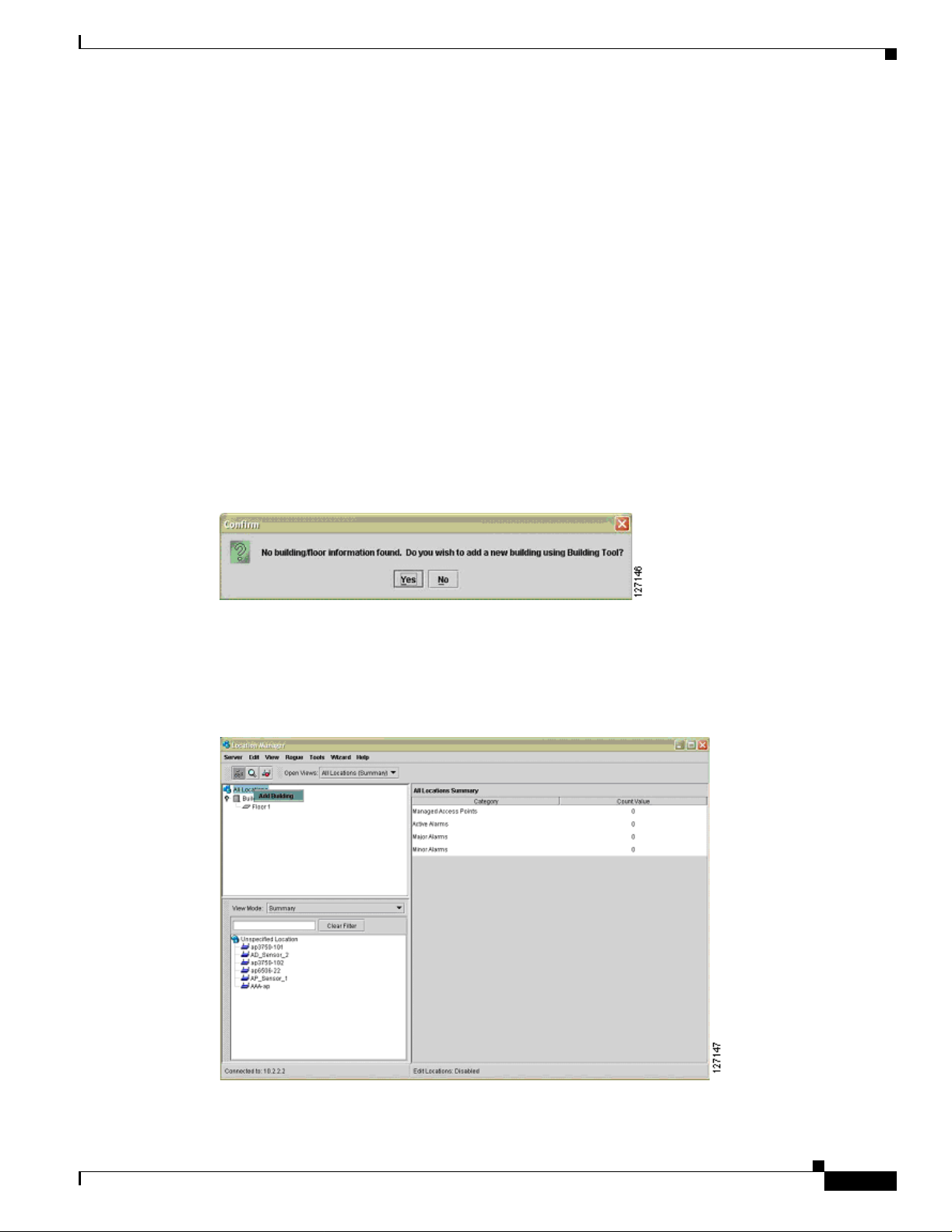
Cisco Structured Wireless-Aware Network (SWAN) Impl ementation Guide
Preparing to Use Cisco SWAN Radio Management
The procedures required before using the Cisco SWAN framework radio management features are as
follows:
• Discover infrastructure access points an d WDS devices
• Import building floorpl ans
• Place access points on the floorplans
• Configure antenna and other access point specific parameters (optional)
The process for com ple tin g the infr astru ctu re a cce ss p oint s and WD S devices di scovery ph ase have
already been c overed i n thi s docum e nt.
T o import building floorplans, log into the CiscoWorks WLSE and navigate to Location Manager. Make
sure the correct java run-time environment (JRE) is installed by checking the JRE version message on
the window. When the system launches, launch the Location Manager.
If no building floorp lans have been i mport ed, a po p-u p wind ow app ears remi nd ing you to impo rt a
building. Select Yes to access the Building Tool (see Figure 14).
Figure 14 Building Tool Pop-Up Window
Implementing the Cisco SWAN Framework
If some buildings have already been imported, you can access the Building T ool by right-clicking on the
All Locations root (see Figure 15) of t he navigation tre e (in the uppe r left-ha nd navigation pane of the
Location Manager) .
Figure 15 Right-Clicking on All Locations
OL-6217-01
Cisco Structured Wire le ss-Aware Network (SW AN) Implem entation Guide
35
Page 36

Implementing the Cisco SWAN Framework
When the building tool is open, follow the wizard steps to create a new building and import floorplans
for each of the building f loor s. Con sul t the C iscoWorks WLSE online help fo r assi stance if n ece ssary.
When the buildings are created and floorplans are imported, managed access points are visible in the
lower left-hand pane of the Loc ation Man ager. Drag and drop the acc ess points to the appr opriate
locations on the floors. Accurate access point placement is important because the CiscoWorks WLSE
radio management tool s u se the Loc ation M anag er a cce ss p oint p osit ions as a ref eren ce wh en ma kin g
internal computations.
As an optional s tep, a cce ss poi nt ant enn a para me ters ca n b e co nfigur ed by righ t-c licki ng on the ac c ess
point in the Location Manager. The antenna parameters include antenna type, azimuth, down-tilt (from
horizon), height, and any estimated cable loss.
When the buildings are created, the access points are placed, and any access point antenna parameters
are configured, the Cisco SWAN framework is ready for radio mana gement .
Cisco SWAN Radio Management Features
An extensive discussion of the deployment and use of Cisco SWAN framework radio management
features is beyond the scope of this document. This section provides some guidance on the next steps for
Cisco SWAN fr amework radio manage ment.
The Cisco SWAN framework radio management features use data gathered by three me thods: acc ess
point radio scan, clien t walkabout, and radio mo nitoring . The ac cess poin t radio scan and radio
monitoring are required methods, and the client walkabout is an optional procedure.
Cisco Structured Wireless-Aware Network (SWAN) Implementation Guide
T ypically , the first radio management step is to run an access point radio scan. This scan can be run from
the Radio Manager > AP Radio Scan option in the CiscoWorks WLSE or as a step in the assisted site
survey tool. The scan is required to create an initial calibrated path loss model of the RF environment,
which considers path-loss between access points (resulting from natural attenuation factors in the RF
environment, such as walls) and identifies potential sources of contention in the RF environment.
The client walkabout is an optional process in which a WLAN client walks the coverage environment,
associating with access points, and collecting specific data for the system to use in radio coverage
calculations. Th e client walkabout can be completed as a step in the assist ed site survey tool or through
the Radio Manager > Clie nt Walkabout interface. A g ood cl ient walkabo ut req uire s a th oro ugh
walkthrough of the coverage environment, ideally in a grid pattern. Data points are gathered
symmetrically acro ss t he c overage e nvironmen t. I f the c lient walk abou t pr oc ed ure ca nno t m eet the se
basic requirements, you should not do one.
Radio monitoring is a process in which infrastructure access points and optional authenticated and
associated WLAN clients regul arl y sample th e RF environment during normal o pera tions. The sample d
data is gathered by the WD S, aggregated, and passed to the CiscoWorks WLSE. Radio monitoring data
is used in coverage calculations, rogue access point detection, and radio interference detection. Radio
monitoring is r equired for ro gue a ccess po int det ection, interf erence d etection , self- healing, and assiste d
site re-survey.
Radio monitor ing options are co nfigur ed thro ugh the inter face at Radio Manager > Radio Monitoring.
Both serving and non-se r ving ch an nels configur e a cce ss poi nts f or ra dio mo nitori ng . Th e ser ving
channel is the normal operating channel for the access point. It is the channel on which associated
WLAN clients are served. When co nfigured to mon itor non- serving channels, t he access poi nt
periodically jumps off the serving ch anne l to sample a non-ser ving chan nel, bef ore resum ing norma l
WLAN client traffic proces sing. Non- se rving c hanne l r adi o moni tor ing typi call y only has a mini mal
impact on normal WLAN data traffic.
36
Cisco SWAN framework radio monitoring c an a lso i n clud e WLAN cl ie nts th at s uppo rt th e ra dio
management features. These client s include Cisco Aironet client adap ters and WLA N client adapt ers
certified to the version 2 Cisco Compatible Extensio ns specification. When WLAN clie nt monito ring is
Cisco Structured Wireless-Aware Network (SWAN) Implementation Guide
OL-6217-01
Page 37

Cisco Structured Wireless-Aware Network (SWAN) Impl ementation Guide
enabled, the WDS periodically requests radio measurement data from supporting registered MNs. These
MNs collect the requested data and send it to the WDS. The WDS aggregates data from the MNs and
passes the aggregated data to the CiscoWorks WLSE. WLAN client monitoring is configured for client
serving and non-serving ch annel s.
After the initial RF en vi ronme nt charac ter iz ation with the ac cess poin t ra dio sca n is complete (either as
part of or indepe nd en t of the assi sted sit e sur vey), and ra dio mon ito ring is c on figured, W LAN
self-healing and assisted site re-survey are en abled on the CiscoWorks WLSE, and some interesting
features are used in the Location Manager. Use Radio Manager > Self Healing to configure self
healing. Consult the CiscoWorks WLSE online help for details on config uring self healing. The a ssisted
site re-survey feature is configured throu gh Radio Manager > Assisted Re-Site Survey. The Location
Manager features include radio coverage (displayed as data rate and signal strength from both the access
point and WLAN client pers pect ive) and rogue access poi nt locat ion.
Implementing the Cisco SWAN Framework
OL-6217-01
Cisco Structured Wire le ss-Aware Network (SW AN) Implem entation Guide
37
Page 38

Implementing the Cisco SWAN Framework
Cisco Structured Wireless-Aware Network (SWAN) Implementation Guide
38
Cisco Structured Wireless-Aware Network (SWAN) Implementation Guide
OL-6217-01
 Loading...