

Page 1

CHA PTER
Adding Cisco IOS Routers to Cisco WAPMS
This chapter explains how to add Cisco IOS-based routers to Cisco WAPMS using the Network
Configuration application in the PAC.
For more information about using Network Configuration, see Chapter 3, “Network Configuration,” in
the Cisco WAN Access Performance Management System Client User Guide, 2.1.
The following topics are discussed in this chapter:
• “Adding Routers in Network Configuration”
• “Configuring ATM and Frame Relay Circuits” section on page 6-5.
Note Throughout the Cisco WAPMS documentation, the term ASE refers to Cisco routers running
SAA-ATM/FR and/or Visual Networks ASE probes.
6
Adding Routers in Network Configuration
In order for Cisco WAPMS to recognize Cisco routers, you must add them to your network using the
Cisco WAPMS PAC Network Configuration Toolset. All configuration tasks for networks, sites, access
lines, ASEs (and routers), and circuits are initiated from the Network Configuration window. See
Figure 6-1.
OL-5512-01
Cisco WAN Access Performance Management System User Guide, 2.1
6-1
Page 2
Adding Routers in Network Configuration
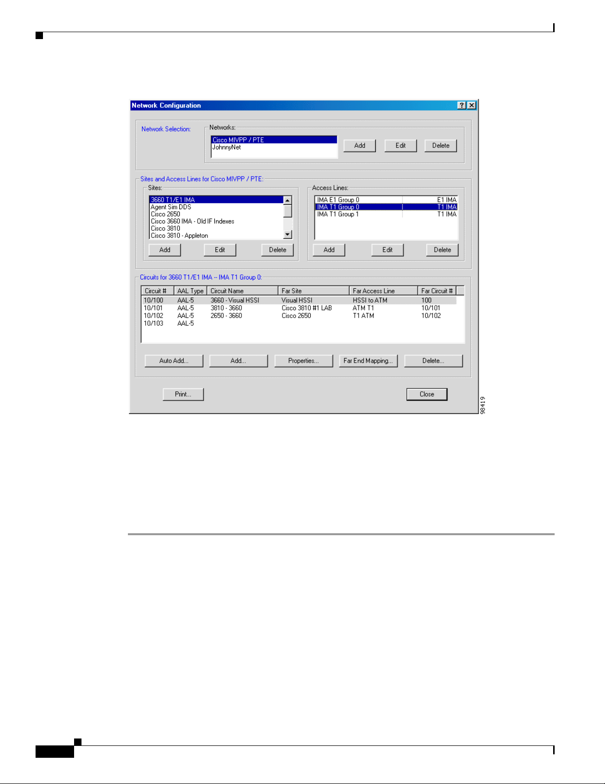
Figure 6-1 Network Configuration Window (Cisco Router Selected)
Chapter 6 Adding Cisco IOS Routers to Cisco WAPMS
As you configure an access line, you can verify settings for the Cisco router on that access line. When
you add a router, the ASE Configuration window is displayed. Here you can verify the WAN link settings
and view the device vendor, product ID, software version installed, along with other important
information about the device.
Adding Routers in Cisco WAPMS
Step 1 On the Cisco WAPMS PAC, close all open PAC Toolsets.
Step 2 Ensure you are connected to the domain in which you want to configure the network.
Step 3 Using the To ols e t Se lec t or, click Network Configuration.
The Network Configuration window appears.
Step 4 In the Network Configuration window, select the network, site, and access line for the router.
Step 5 In the Access Lines pane:
• when you are editing an access line, select an access line, then click Edit.
The Edit an Access Line window is displayed.
• when you are adding a new access line, click Add.
The Add a New Access Line window is displayed.
6-2
Cisco WAN Access Performance Management System User Guide, 2.1
OL-5512-01
Page 3

Chapter 6 Adding Cisco IOS Routers to Cisco WAPMS
Step 6 In the Add/Edit an Access Line window, enter the name of the access line and the IP address of the
device.
Figure 6-2 Edit an Access Line Window
Adding Routers in Network Configuration
OL-5512-01
Step 7
Click ASE Setup.
The ASE Configuration window, shown in Figure 6-3, appears, where you can verify the ATM or Frame
Relay link settings for the router.
Cisco WAN Access Performance Management System User Guide, 2.1
6-3
Page 4

Adding Routers in Network Configuration
Figure 6-3 ASE Configuration Window
Chapter 6 Adding Cisco IOS Routers to Cisco WAPMS
Step 8 In the ASE Configuration window for ATM routers, click ATM to verify the WAN link layer parameters
for the router (this option is not available for Frame Relay).
The ATM Link Layer Configuration window appears, as shown in Figure 6-4.
Figure 6-4 ATM Link Layer Configuration Window
For ATM read-only settings, see Table 6-1.
Table 6-1 ATM Link Layer Settings for Cisco Routers
Option Description
Scramble Configuration Indicates whether payload data is scrambled at transmission and
unscrambled when received. Displayed values are Enabled or
Disabled. This parameter is set at the device during installation.
Framing Method of cell synchronization. Displayed values are HEC (header
error control) or PLCP (physical layer convergence protocol). This
parameter is set at the device during installation.
6-4
Step 9 Once you have verified the ATM link layer settings, click Close.
Step 10 Click Close in the ASE Configuration window.
Step 11 Click OK in the Add/Edit an Access Line window to apply the settings.
Cisco WAN Access Performance Management System User Guide, 2.1
OL-5512-01
Page 5

Chapter 6 Adding Cisco IOS Routers to Cisco WAPMS
Configuring ATM and Frame Relay Circuits
You configure Frame Relay or ATM virtual circuits for the router in the Circuits pane of the Network
Configuration window (see Figure 6-1 on page 6-2). The Circuits box shows the circuit number, name,
AAL type (for ATM), far site, far access line, and far circuit number.
Configuring circuits involves:
• adding the circuit end points to the access lines
• customizing the circuit end points (optional)
• configuring the circuit connections between the circuit end points.
To view read-only circuit settings, click Properties. For Frame Relay circuit information, see Figure 6-5
and Table 6-2. For ATM circuit information, see Figure 6-6 and Table 6-3.
Figure 6-5 DLCI Configuration Window for Frame Relay Circuits
Configuring ATM and Frame Relay Circuits
Table 6-2 Frame Relay DLCI Settings for Cisco Routers
Option Description
Committed Information Rate (CIR) Maximum data rate at which the router/FRAD can send data
without risk of dropped packets. This setting is applied to all
DLCIs discovered by the ASE.
Excess Burst Allowed (Be) Maximum allowable excess burst rate beyond the CIR; can be
determined by router or port. Calculated as port speed - CIR.
This setting is applied to all DLCIs discovered by the ASE.
OL-5512-01
Cisco WAN Access Performance Management System User Guide, 2.1
6-5
Page 6

Configuring ATM and Frame Relay Circuits
Figure 6-6 VPI/VCI Configuration Window for ATM Circuits
Table 6-3 ATM VC Settings for Cisco Routers
Option Description
Peak Cell Rate (PCR) Maximum rate at which cells can be sent over this VPI/VCI.
Sustained Cell Rate (SCR) Maximum average rate at which cells can be sent over this VPI/VCI.
ATM A d apt atio n La yer Layer of ATM protocols responsible for packaging data and voice
Chapter 6 Adding Cisco IOS Routers to Cisco WAPMS
into a format that can be handled by ATM. Displayed values are
AAL-2 and AAL-5.
For more information about adding circuits, adding circuit end points, and checking circuit properties,
seeChapter 3, “Network Configuration,” in the Cisco WAN Access Performance Management System
Client User Guide, 2.1.
6-6
Cisco WAN Access Performance Management System User Guide, 2.1
OL-5512-01
 Loading...