

Page 1
Firewall Mode Overview
This chapter describes how the firewall works in each firewall mode. To set the firewall mode, see the
“Setting Transparent or Routed Firewall Mode” section on page 2-5.
Note In multiple context mode, you cannot set the firewall mode separately for each context; you can only set
the firewall mode for the entire security appliance.
This chapter includes the following sections:
• Routed Mode Overview, page 15-1
• Transparent Mode Overview, page 15-7
Routed Mode Overview
CHAP T E R
15
In routed mode, the security appliance is considered to be a router hop in the network. It can use OSPF
or RIP (in single context mode). Routed mode supports many interfaces. Each interface is on a different
subnet. You can share interfaces between contexts.
This section includes the following topics:
• IP Routing Support, page 15-1
• How Data Moves Through the Security Appliance in Routed Firewall Mode, page 15-1
IP Routing Support
The security appliance acts as a router between connected networks, and each interface requires an
IP address on a different subnet. In single context mode, the routed firewall supports OSPF and RIP.
Multiple context mode supports static routes only. We recommend using the advanced routing
capabilities of the upstream and downstream routers instead of relying on the security appliance for
extensive routing needs.
How Data Moves Through the Security Appliance in Routed Firewall Mode
This section describes how data moves through the security appliance in routed firewall mode, and
includes the following topics:
OL-12172-01
Cisco Security Appliance Command Line Configuration Guide
15-1
Page 2
Routed Mode Overview
• An Inside User Visits a Web Server, page 15-2
• An Outside User Visits a Web Server on the DMZ, page 15-3
• An Inside User Visits a Web Server on the DMZ, page 15-4
• An Outside User Attempts to Access an Inside Host, page 15-5
• A DMZ User Attempts to Access an Inside Host, page 15-6
An Inside User Visits a Web Server
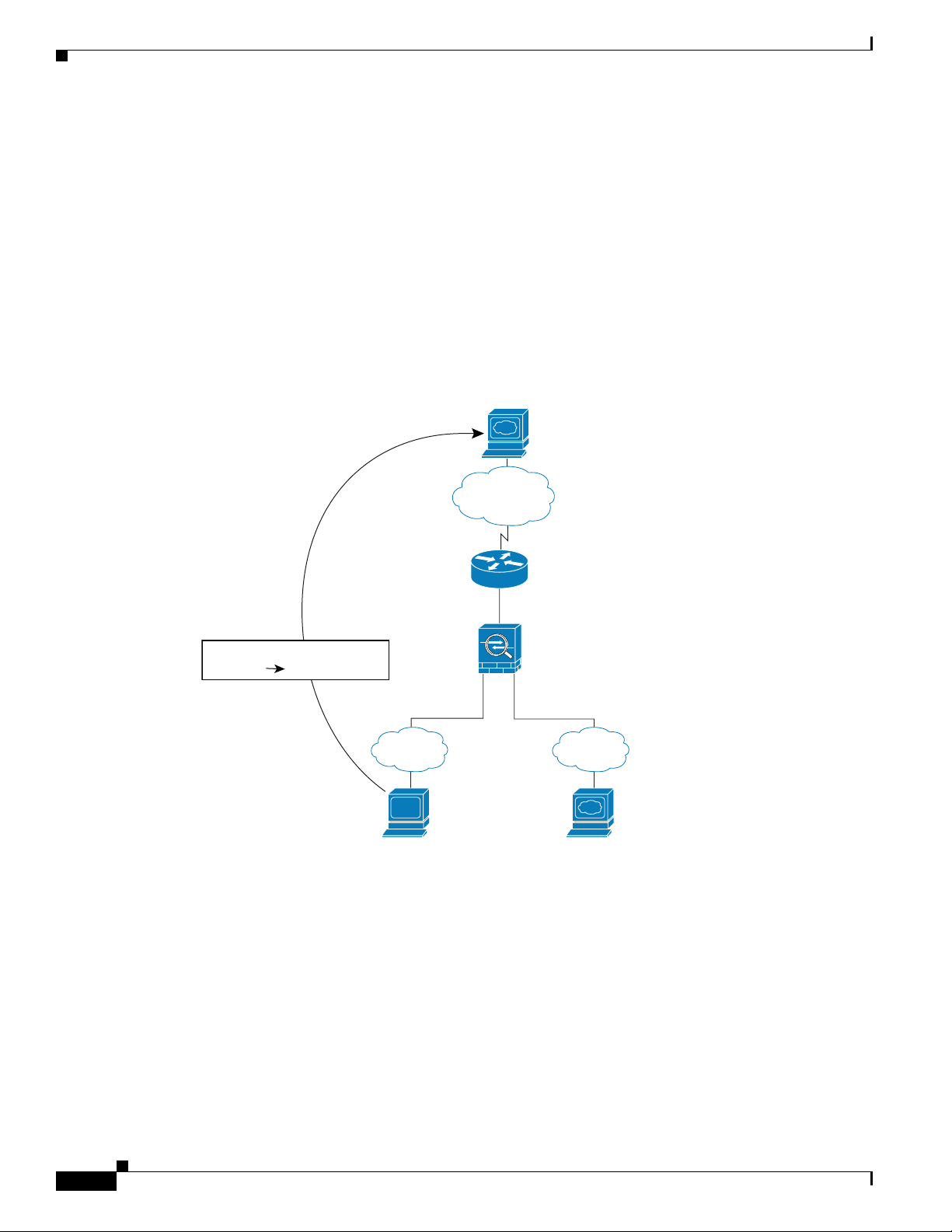
Figure 15-1 shows an inside user accessing an outside web server.
Figure 15-1 Inside to Outside
Chapter 15 Firewall Mode Overview
www.example.com
Outside
209.165.201.2
Source Addr Translation
209.165.201.1010.1.2.27
Inside DMZ
User
10.1.2.27
10.1.1.110.1.2.1
92404
Web Server
10.1.1.3
The following steps describe how data moves through the security appliance (see Figure 15-1):
1. The user on the inside network requests a web page from www.example.com.
15-2
2. The security appliance receives the packet and because it is a new session, the security appliance
verifies that the packet is allowed according to the terms of the security policy (access lists, filters,
AAA).
For multiple context mode, the security appliance first classifies the packet according to either a
unique interface or a unique destination address associated with a context; the destination address
is associated by matching an address translation in a context. In this case, the interface would be
unique; the www.example.com IP address does not have a current address translation in a context.
Cisco Security Appliance Command Line Configuration Guide
OL-12172-01
Page 3
Chapter 15 Firewall Mode Overview
3. The security appliance translates the local source address (10.1.2.27) to the global address
209.165.201.10, which is on the outside interface subnet.
The global address could be on any subnet, but routing is simplified when it is on the outside
interface subnet.
4. The security appliance then records that a session is established and forwards the packet from the
outside interface.
5. When www.example.com responds to the request, the packet goes through the security appliance,
and because the session is already established, the packet bypasses the many lookups associated
with a new connection. The security appliance performs NAT by translating the global destination
address to the local user address, 10.1.2.27.
6. The security appliance forwards the packet to the inside user.
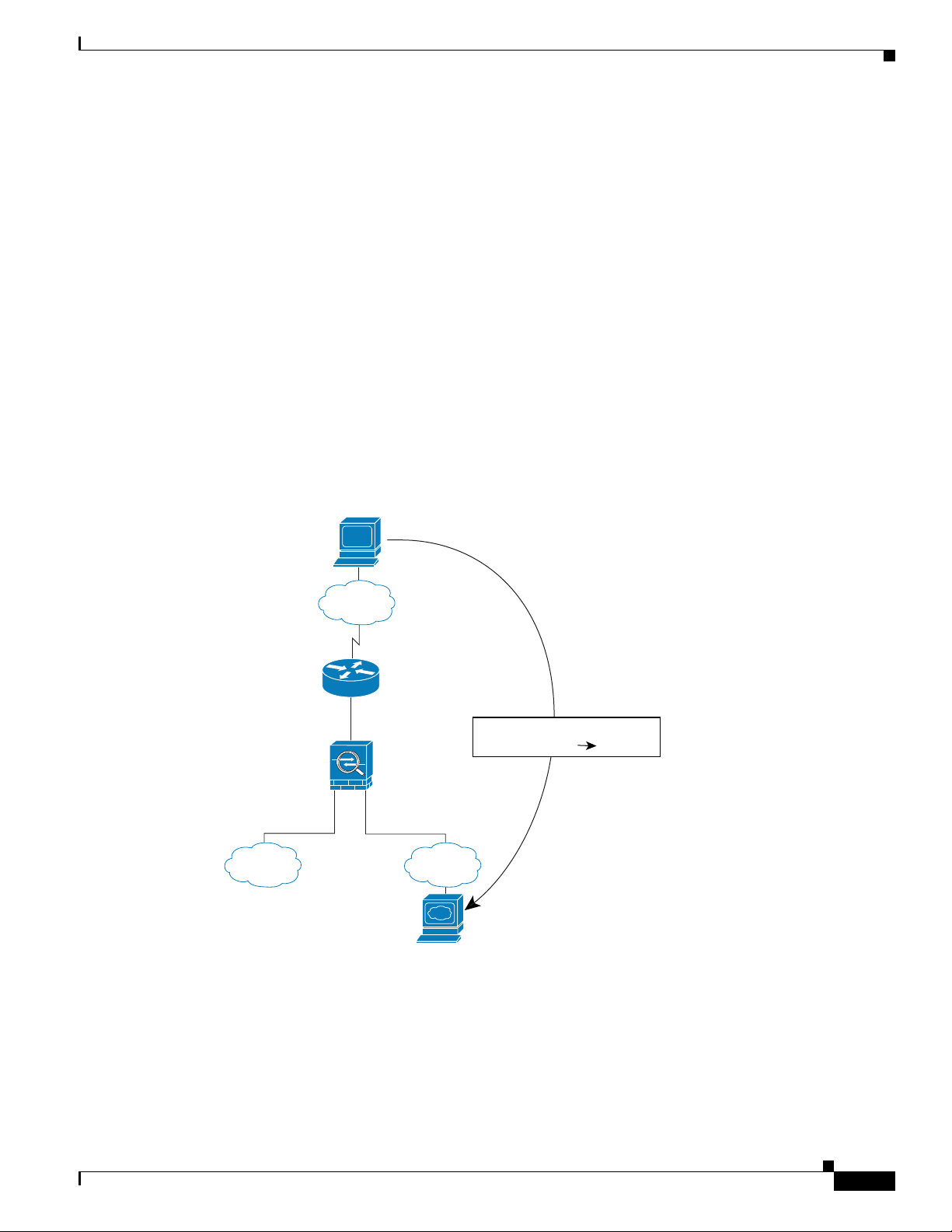
An Outside User Visits a Web Server on the DMZ
Figure 15-2 shows an outside user accessing the DMZ web server.
Figure 15-2 Outside to DMZ
Routed Mode Overview
Inside
User
Outside
209.165.201.2
10.1.1.110.1.2.1
DMZ
Web Server
10.1.1.3
Dest Addr Translation
209.165.201.3
10.1.1.13
92406
OL-12172-01
The following steps describe how data moves through the security appliance (see Figure 15-2):
1. A user on the outside network requests a web page from the DMZ web server using the global
destination address of 209.165.201.3, which is on the outside interface subnet.
Cisco Security Appliance Command Line Configuration Guide
15-3
Page 4
Routed Mode Overview
2. The security appliance receives the packet and because it is a new session, the security appliance
verifies that the packet is allowed according to the terms of the security policy (access lists, filters,
AAA).
For multiple context mode, the security appliance first classifies the packet according to either a
unique interface or a unique destination address associated with a context; the destination address
is associated by matching an address translation in a context. In this case, the classifier “knows” that
the DMZ web server address belongs to a certain context because of the server address translation.
3. The security appliance translates the destination address to the local address 10.1.1.3.
4. The security appliance then adds a session entry to the fast path and forwards the packet from the
DMZ interface.
5. When the DMZ web server responds to the request, the packet goes through the security appliance
and because the session is already established, the packet bypasses the many lookups associated
with a new connection. The security appliance performs NAT by translating the local source address
to 209.165.201.3.
6. The security appliance forwards the packet to the outside user.
An Inside User Visits a Web Server on the DMZ
Chapter 15 Firewall Mode Overview
Figure 15-3 shows an inside user accessing the DMZ web server.
Figure 15-3 Inside to DMZ
Outside
209.165.201.2
10.1.1.110.1.2.1
Inside DMZ
92403
User
10.1.2.27
Web Server
10.1.1.3
15-4
Cisco Security Appliance Command Line Configuration Guide
OL-12172-01
Page 5
Chapter 15 Firewall Mode Overview
The following steps describe how data moves through the security appliance (see Figure 15-3):
1. A user on the inside network requests a web page from the DMZ web server using the destination
address of 10.1.1.3.
2. The security appliance receives the packet and because it is a new session, the security appliance
verifies that the packet is allowed according to the terms of the security policy (access lists, filters,
AAA).
For multiple context mode, the security appliance first classifies the packet according to either a
unique interface or a unique destination address associated with a context; the destination address
is associated by matching an address translation in a context. In this case, the interface is unique;
the web server IP address does not have a current address translation.
3. The security appliance then records that a session is established and forwards the packet out of the
DMZ interface.
4. When the DMZ web server responds to the request, the packet goes through the fast path, which lets
the packet bypass the many lookups associated with a new connection.
5. The security appliance forwards the packet to the inside user.
An Outside User Attempts to Access an Inside Host
Routed Mode Overview
Figure 15-4 shows an outside user attempting to access the inside network.
Figure 15-4 Outside to Inside
www.example.com
Outside
209.165.201.2
10.1.1.110.1.2.1
Inside DMZ
OL-12172-01
User
10.1.2.27
92407
Cisco Security Appliance Command Line Configuration Guide
15-5
Page 6

Routed Mode Overview
The following steps describe how data moves through the security appliance (see Figure 15-4):
1. A user on the outside network attempts to reach an inside host (assuming the host has a routable
IP address).
If the inside network uses private addresses, no outside user can reach the inside network without
NAT. The outside user might attempt to reach an inside user by using an existing NAT session.
2. The security appliance receives the packet and because it is a new session, the security appliance
verifies if the packet is allowed according to the security policy (access lists, filters, AAA).
3. The packet is denied, and the security appliance drops the packet and logs the connection attempt.
If the outside user is attempting to attack the inside network, the security appliance employs many
technologies to determine if a packet is valid for an already established session.
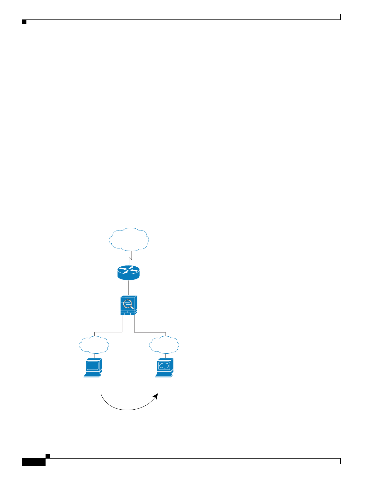
A DMZ User Attempts to Access an Inside Host
Figure 15-5 shows a user in the DMZ attempting to access the inside network.
Figure 15-5 DMZ to Inside
Chapter 15 Firewall Mode Overview
Outside
209.165.201.2
10.1.1.110.1.2.1
Inside DMZ
92402
User
10.1.2.27
Web Server
10.1.1.3
The following steps describe how data moves through the security appliance (see Figure 15-5):
1. A user on the DMZ network attempts to reach an inside host. Because the DMZ does not have to
route the traffic on the Internet, the private addressing scheme does not prevent routing.
2. The security appliance receives the packet and because it is a new session, the security appliance
verifies if the packet is allowed according to the security policy (access lists, filters, AAA).
15-6
3. The packet is denied, and the security appliance drops the packet and logs the connection attempt.
Cisco Security Appliance Command Line Configuration Guide
OL-12172-01
Page 7

Chapter 15 Firewall Mode Overview
Transparent Mode Overview
Traditionally, a firewall is a routed hop and acts as a default gateway for hosts that connect to one of its
screened subnets. A transparent firewall, on the other hand, is a Layer 2 firewall that acts like a “bump
in the wire,” or a “stealth firewall,” and is not seen as a router hop to connected devices.
This section describes transparent firewall mode, and includes the following topics:
• Transparent Firewall Network, page 15-7
• Allowing Layer 3 Traffic, page 15-7
• Allowed MAC Addresses, page 15-7
• Passing Traffic Not Allowed in Routed Mode, page 15-8
• MAC Address vs. Route Lookups, page 15-8
• Using the Transparent Firewall in Your Network, page 15-9
• Transparent Firewall Guidelines, page 15-9
• Unsupported Features in Transparent Mode, page 15-10
• How Data Moves Through the Transparent Firewall, page 15-11
Transparent Mode Overview
Transparent Firewall Network
The security appliance connects the same network on its inside and outside interfaces. Because the
firewall is not a routed hop, you can easily introduce a transparent firewall into an existing network.
Allowing Layer 3 Traffic
IPv4 traffic is allowed through the transparent firewall automatically from a higher security interface to
a lower security interface, without an access list. ARPs are allowed through the transparent firewall in
both directions without an access list. ARP traffic can be controlled by ARP inspection. For Layer 3
traffic travelling from a low to a high security interface, an extended access list is required on the low
security interface. See the “Adding an Extended Access List” section on page 16-5 for more information.
Allowed MAC Addresses
The following destination MAC addresses are allowed through the transparent firewall. Any MAC
address not on this list is dropped.
• TRUE broadcast destination MAC address equal to FFFF.FFFF.FFFF
• IPv4 multicast MAC addresses from 0100.5E00.0000 to 0100.5EFE.FFFF
• IPv6 multicast MAC addresses from 3333.0000.0000 to 3333.FFFF.FFFF
OL-12172-01
• BPDU multicast address equal to 0100.0CCC.CCCD
• Appletalk multicast MAC addresses from 0900.0700.0000 to 0900.07FF.FFFF
Cisco Security Appliance Command Line Configuration Guide
15-7
Page 8

Transparent Mode Overview
Passing Traffic Not Allowed in Routed Mode
In routed mode, some types of traffic cannot pass through the security appliance even if you allow it in
an access list. The transparent firewall, however, can allow almost any traffic through using either an
extended access list (for IP traffic) or an EtherType access list (for non-IP traffic).
Note The transparent mode security appliance does not pass CDP packets or IPv6 packets, or any packets that
do not have a valid EtherType greater than or equal to 0x600. For example, you cannot pass IS-IS
packets. An exception is made for BPDUs, which are supported.
For example, you can establish routing protocol adjacencies through a transparent firewall; you can
allow OSPF, RIP, EIGRP, or BGP traffic through based on an extended access list. Likewise, protocols
like HSRP or VRRP can pass through the security appliance.
Non-IP traffic (for example AppleTalk, IPX, BPDUs, and MPLS) can be configured to go through using
an EtherType access list.
For features that are not directly supported on the transparent firewall, you can allow traffic to pass
through so that upstream and downstream routers can support the functionality. For example, by using
an extended access list, you can allow DHCP traffic (instead of the unsupported DHCP relay feature) or
multicast traffic such as that created by IP/TV.
Chapter 15 Firewall Mode Overview
MAC Address vs. Route Lookups
When the security appliance runs in transparent mode without NAT, the outgoing interface of a packet
is determined by performing a MAC address lookup instead of a route lookup. Route statements can still
be configured, but they only apply to security appliance-originated traffic. For example, if your syslog
server is located on a remote network, you must use a static route so the security appliance can reach
that subnet.
An exception to this rule is when you use voice inspections and the endpoint is at least one hop away
from the security appliance. For example, if you use the transparent firewall between a CCM and an
H.323 gateway, and there is a router between the transparent firewall and the H.323 gateway, then you
need to add a static route on the security appliance for the H.323 gateway for successful call completion.
If you use NAT, then the security appliance uses a route lookup instead of a MAC address lookup. In
some cases, you will need static routes. For example, if the real destination address is not
directly-connected to the security appliance, then you need to add a static route on the security appliance
for the real destination address that points to the downstream router.
15-8
Cisco Security Appliance Command Line Configuration Guide
OL-12172-01
Page 9

Chapter 15 Firewall Mode Overview
Using the Transparent Firewall in Your Network
Figure 15-6 shows a typical transparent firewall network where the outside devices are on the same
subnet as the inside devices. The inside router and hosts appear to be directly connected to the outside
router.
Figure 15-6 Transparent Firewall Network
Internet
10.1.1.1
Transparent Mode Overview
Network A
10.1.1.3
192.168.1.2
Network B
Transparent Firewall Guidelines
Follow these guidelines when planning your transparent firewall network:
• A management IP address is required; for multiple context mode, an IP address is required for each
context.
Unlike routed mode, which requires an IP address for each interface, a transparent firewall has an
IP address assigned to the entire device. The security appliance uses this IP address as the source
address for packets originating on the security appliance, such as system messages or AAA
communications.
The management IP address must be on the same subnet as the connected network. You cannot set
the subnet to a host subnet (255.255.255.255).
You can configure an IP address for the Management 0/0 management-only interface. This IP
address can be on a separate subnet from the main management IP address.
Management IP
10.1.1.2
92411
OL-12172-01
• The transparent security appliance uses an inside interface and an outside interface only. If your
platform includes a dedicated management interface, you can also configure the management
interface or subinterface for management traffic only.
Cisco Security Appliance Command Line Configuration Guide
15-9
Page 10

Transparent Mode Overview
In single mode, you can only use two data interfaces (and the dedicated management interface, if
available) even if your security appliance includes more than two interfaces.
• Each directly connected network must be on the same subnet.
• Do not specify the security appliance management IP address as the default gateway for connected
devices; devices need to specify the router on the other side of the security appliance as the default
gateway.
• For multiple context mode, each context must use different interfaces; you cannot share an interface
across contexts.
• For multiple context mode, each context typically uses a different subnet. You can use overlapping
subnets, but your network topology requires router and NAT configuration to make it possible from
a routing standpoint.
Unsupported Features in Transparent Mode
Table 15-1 lists the features are not supported in transparent mode.
Table 15-1 Unsupported Features in Transparent Mode
Chapter 15 Firewall Mode Overview
Feature Description
Dynamic DNS —
DHCP relay The transparent firewall can act as a DHCP server, but it does not
support the DHCP relay commands. DHCP relay is not required
because you can allow DHCP traffic to pass through using two
extended access lists: one that allows DCHP requests from the inside
interface to the outside, and one that allows the replies from the server
in the other direction.
Dynamic routing protocols You can, however, add static routes for traffic originating on the
security appliance. You can also allow dynamic routing protocols
through the security appliance using an extended access list.
IPv6 You also cannot allow IPv6 using an EtherType access list.
Multicast You can allow multicast traffic through the security appliance by
allowing it in an extended access list.
QoS —
VPN termination for through
traffic
The transparent firewall supports site-to-site VPN tunnels for
management connections only. It does not terminate VPN connections
for traffic through the security appliance. You can pass VPN traffic
through the security appliance using an extended access list, but it
does not terminate non-management connections. WebVPN is also not
supported.
15-10
Cisco Security Appliance Command Line Configuration Guide
OL-12172-01
Page 11

Chapter 15 Firewall Mode Overview
How Data Moves Through the Transparent Firewall
Figure 15-7 shows a typical transparent firewall implementation with an inside network that contains a
public web server. The security appliance has an access list so that the inside users can access Internet
resources. Another access list lets the outside users access only the web server on the inside network.
Figure 15-7 Typical Transparent Firewall Data Path
www.example.com
Internet
Transparent Mode Overview
209.165.201.2
Management IP
209.165.201.6
209.165.200.230
Web Server
209.165.200.225
Host
209.165.201.3
92412
This section describes how data moves through the security appliance, and includes the following topics:
• An Inside User Visits a Web Server, page 15-12
• An Inside User Visits a Web Server Using NAT, page 15-13
• An Outside User Visits a Web Server on the Inside Network, page 15-14
• An Outside User Attempts to Access an Inside Host, page 15-15
OL-12172-01
Cisco Security Appliance Command Line Configuration Guide
15-11
Page 12

Transparent Mode Overview
An Inside User Visits a Web Server
Figure 15-8 shows an inside user accessing an outside web server.
Figure 15-8 Inside to Outside
www.example.com
Chapter 15 Firewall Mode Overview
Internet
209.165.201.2
Management IP
209.165.201.6
Host
209.165.201.3
92408
The following steps describe how data moves through the security appliance (see Figure 15-8):
1. The user on the inside network requests a web page from www.example.com.
2. The security appliance receives the packet and adds the source MAC address to the MAC address
table, if required. Because it is a new session, it verifies that the packet is allowed according to the
terms of the security policy (access lists, filters, AAA).
For multiple context mode, the security appliance first classifies the packet according to a unique
interface.
3. The security appliance records that a session is established.
4. If the destination MAC address is in its table, the security appliance forwards the packet out of the
outside interface. The destination MAC address is that of the upstream router, 209.186.201.2.
If the destination MAC address is not in the security appliance table, the security appliance attempts
to discover the MAC address by sending an ARP request and a ping. The first packet is dropped.
15-12
5. The web server responds to the request; because the session is already established, the packet
bypasses the many lookups associated with a new connection.
6. The security appliance forwards the packet to the inside user.
Cisco Security Appliance Command Line Configuration Guide
OL-12172-01
Page 13

Chapter 15 Firewall Mode Overview
An Inside User Visits a Web Server Using NAT
Figure 15-8 shows an inside user accessing an outside web server.
Figure 15-9 Inside to Outside with NAT
www.example.com
Internet
Static route on router
to 209.165.201.0/27
through security appliance
Transparent Mode Overview
Source Addr Translation
209.165.201.1010.1.2.27
10.1.2.1
Security
appliance
Management IP
10.1.2.2
Host
10.1.2.27
191243
The following steps describe how data moves through the security appliance (see Figure 15-8):
1. The user on the inside network requests a web page from www.example.com.
2. The security appliance receives the packet and adds the source MAC address to the MAC address
table, if required. Because it is a new session, it verifies that the packet is allowed according to the
terms of the security policy (access lists, filters, AAA).
For multiple context mode, the security appliance first classifies the packet according to a unique
interface.
3. The security appliance translates the real address (10.1.2.27) to the mapped address 209.165.201.10.
Because the mapped address is not on the same network as the outside interface, then be sure the
upstream router has a static route to the mapped network that points to the security appliance.
4. The security appliance then records that a session is established and forwards the packet from the
outside interface.
OL-12172-01
5. If the destination MAC address is in its table, the security appliance forwards the packet out of the
outside interface. The destination MAC address is that of the upstream router, 209.165.201.2.
If the destination MAC address is not in the security appliance table, the security appliance attempts
to discover the MAC address by sending an ARP request and a ping. The first packet is dropped.
6. The web server responds to the request; because the session is already established, the packet
bypasses the many lookups associated with a new connection.
Cisco Security Appliance Command Line Configuration Guide
15-13
Page 14

Transparent Mode Overview
7. The security appliance performs NAT by translating the mapped address to the real address,
10.1.2.27.
An Outside User Visits a Web Server on the Inside Network
Figure 15-10 shows an outside user accessing the inside web server.
Figure 15-10 Outside to Inside
Host
Internet
Chapter 15 Firewall Mode Overview
209.165.201.2
Management IP
209.165.201.6
209.165.201.1
209.165.200.230
Web Server
209.165.200.225
92409
The following steps describe how data moves through the security appliance (see Figure 15-10):
1. A user on the outside network requests a web page from the inside web server.
2. The security appliance receives the packet and adds the source MAC address to the MAC address
table, if required. Because it is a new session, it verifies that the packet is allowed according to the
terms of the security policy (access lists, filters, AAA).
For multiple context mode, the security appliance first classifies the packet according to a unique
interface.
15-14
3. The security appliance records that a session is established.
4. If the destination MAC address is in its table, the security appliance forwards the packet out of the
inside interface. The destination MAC address is that of the downstream router, 209.186.201.1.
Cisco Security Appliance Command Line Configuration Guide
OL-12172-01
Page 15

Chapter 15 Firewall Mode Overview
If the destination MAC address is not in the security appliance table, the security appliance attempts
to discover the MAC address by sending an ARP request and a ping. The first packet is dropped.
5. The web server responds to the request; because the session is already established, the packet
bypasses the many lookups associated with a new connection.
6. The security appliance forwards the packet to the outside user.
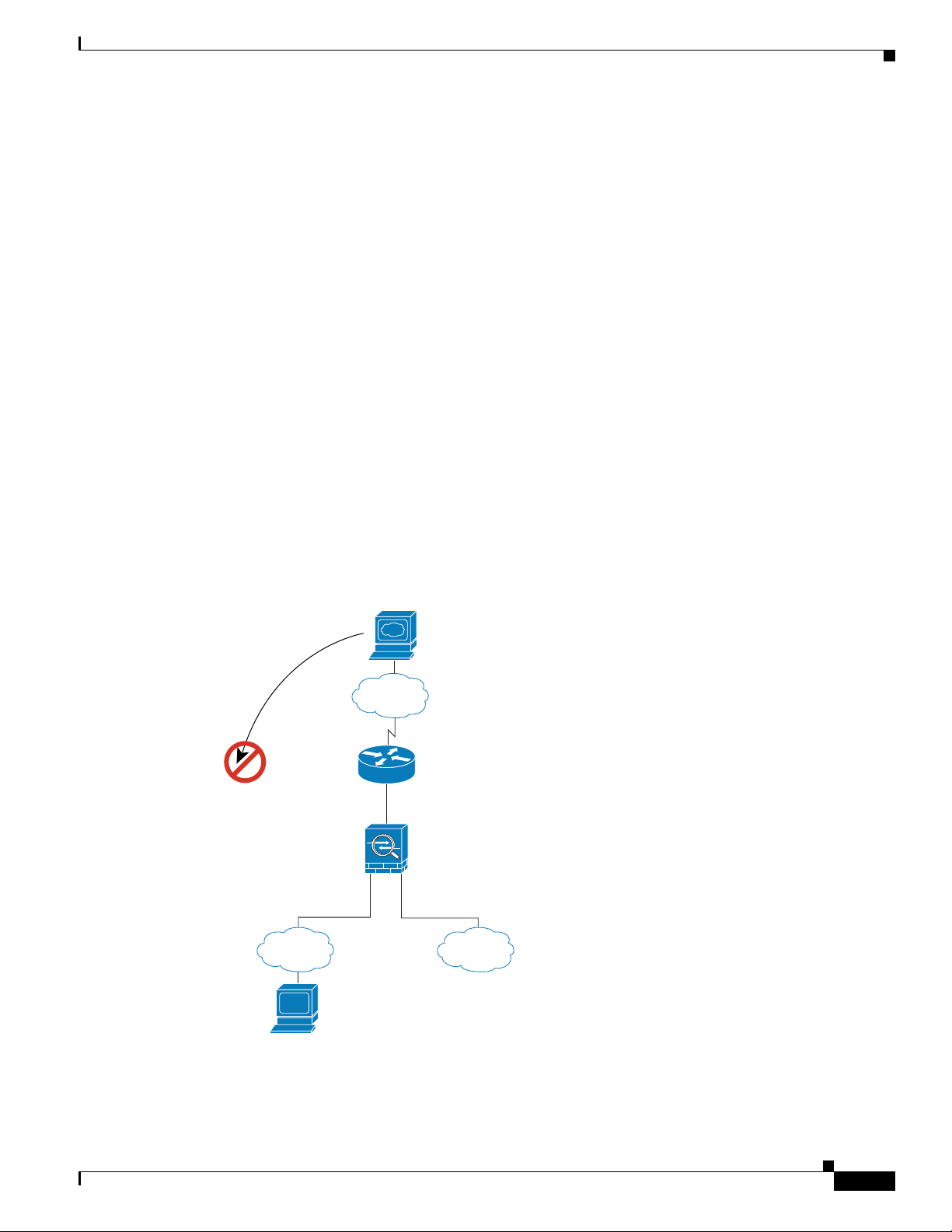
An Outside User Attempts to Access an Inside Host
Figure 15-11 shows an outside user attempting to access a host on the inside network.
Figure 15-11 Outside to Inside
Host
Internet
Transparent Mode Overview
209.165.201.2
Management IP
209.165.201.6
92410
Host
209.165.201.3
The following steps describe how data moves through the security appliance (see Figure 15-11):
1. A user on the outside network attempts to reach an inside host.
2. The security appliance receives the packet and adds the source MAC address to the MAC address
table, if required. Because it is a new session, it verifies if the packet is allowed according to the
terms of the security policy (access lists, filters, AAA).
For multiple context mode, the security appliance first classifies the packet according to a unique
interface.
3. The packet is denied, and the security appliance drops the packet.
4. If the outside user is attempting to attack the inside network, the security appliance employs many
technologies to determine if a packet is valid for an already established session.
OL-12172-01
Cisco Security Appliance Command Line Configuration Guide
15-15
Page 16

Transparent Mode Overview
Chapter 15 Firewall Mode Overview
15-16
Cisco Security Appliance Command Line Configuration Guide
OL-12172-01
 Loading...