

Page 1

CHAPTER
12
IP Video Telephony Configuration
This topic provides an overview of how IP Video Telephony was configured for Cisco IP
Communications Release 5.1(1) testing. This topic does not include detailed installation and
configuration instructions. Rather, it is intended to provide you with guidance and serve as a reference
as you set up video devices in your IP telephony solution.
For additional information and guidelines for implementing Cisco IP Video Telephony, refer to the
documents listed Table 12-1. You can also refer to documentation provided by the vendors of Tandberg
video endpoints and Polycom video endpoints.
Table 12-1 IP Video Telephony Related Documentation
Document Reference
Cisco Unified CallManager System Guide
“Understanding Video Telephony” chapter
IP Video Telephony Solution Reference
Network Design (SRND) for
Cisco Unified CallManager
Cisco UnifiedVideoconferencing3500 Series
video conferencing products documentation
Cisco Unified Video Advantage
documentation
Deploying Video Telephony http://cco/en/US/partner/about/ac123/ac114/ac173/
http://www.cisco.com/univercd/cc/td/doc/product/
voice/c_callmg/5_0/sys_ad/5_0_2/ccmsys/index.htm
http://www.cisco.com/go/srnd
http://www.cisco.com/en/US/products/hw/video/
ps1870/tsd_products_support_series_home.html
http://www.cisco.com/en/US/products/sw/voicesw/
ps5662/tsd_products_support_series_home.html
Q3-04/tech_videotel.html
(You must be a registered user of Cisco.com to access
this URL)
OL-11591-01
This topic includes the following sections:
• IP Video Telephony Components and Topology, page 12-2
• Supported Call Types, page 12-4
• Call Routing, page 12-5
• Gatekeeper Configuration for IP Video Telephony, page 12-7
• Cisco Unified Videoconferencing 3540 MCU Conference Bridge Configuration for IP Video
Telephony, page 12-9
• Cisco Unified Videoconferencing Gateway Configuration for Video PSTN Gateway, page 12-13
System Test Architecture Reference Manual for IP Telephony
12-1
Page 2

Chapter 12 IP Video Telephony Configuration
IP Video Telephony Components and Topology
• Cisco Unified CallManager Configuration for IP Video Telephony, page 12-16
• Video Endpoints Configuration, page 12-26
IP Video Telephony Components and Topology
The IP Video Telephony test deployment included the following components:
• Cisco Unified IP Phone 7985
• Cisco Unified Video Advantage
• Cisco Unified Videoconferencing 3521 with EMP
• Cisco Unified Videoconferencing 3526
• Cisco Unified Videoconferencing 3540 MC10A/MC10A MCU with EMP3
• Cisco Unified Videoconferencing 3540-GW2P
• Cisco Unified Videoconferencing 3545 MCU with EMP3
• Cisco Unified Videoconferencing 3545-GW2P
• Third-party SCCP endpoints
• Third-party H.323 endpoints
• SCCP/H.323 conference bridge
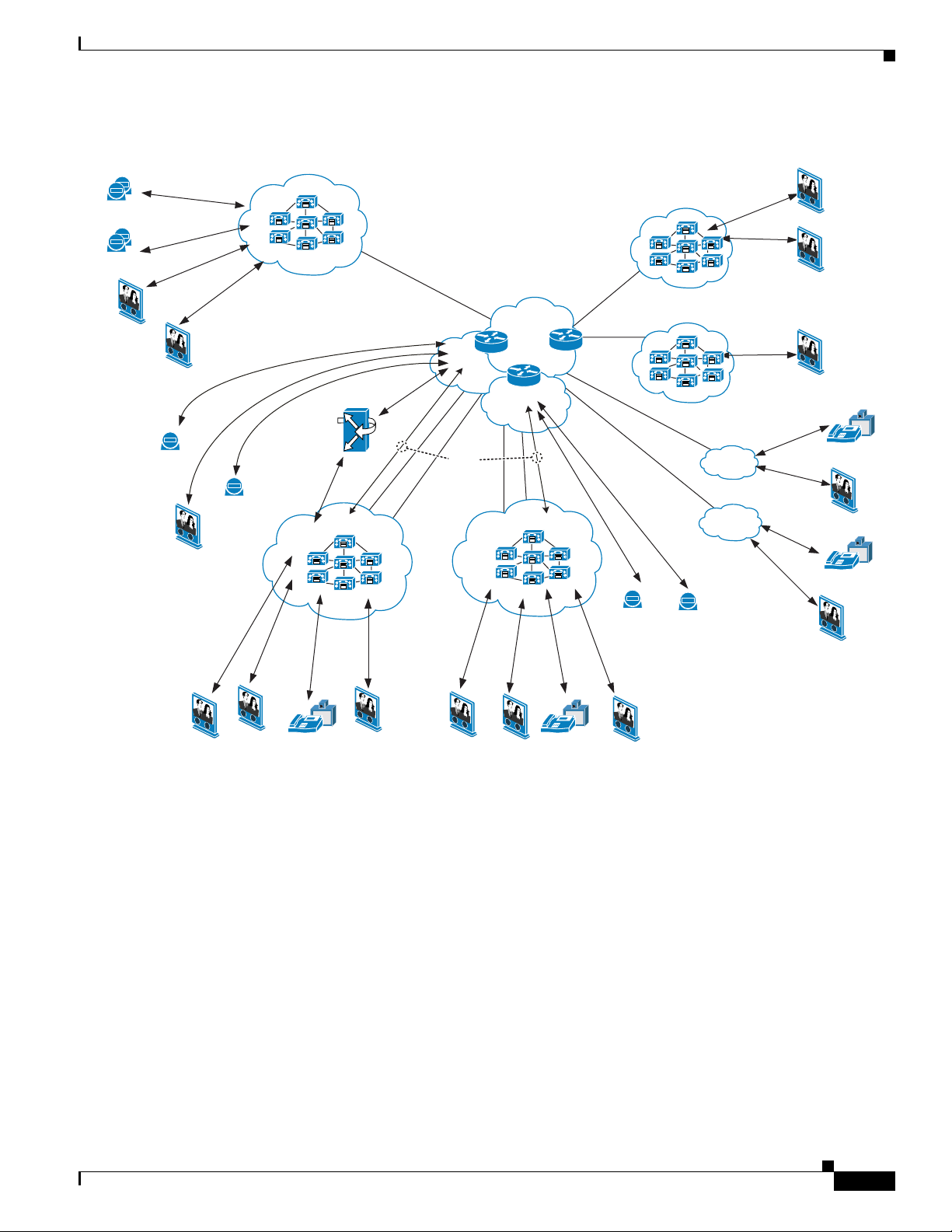
Figure 12-1 shows how Cisco IP Video Telephony was deployed in Cisco IP Communications Release
5.1(1).
12-2
System Test Architecture Reference Manual for IP Telephony
OL-11591-01
Page 3
Chapter 12 IP Video Telephony Configuration
Figure 12-1 IP Video Telephony Topology
Dallas
Dallas
(DFW)
(DFW)
H.323
H.323
Videoconferencing
Videoconferencing
MCU
MCU
SCCP
(SJC)
(SJC)
SCCP
IP
IP
SCCP
Tandberg
MXP 990 x 2
Polycom
VSX7000 x 2
Tandberg
T1000 MXP
7985
Tandberg
MXP 990
Tandberg
T1000
SIP
SIP
H.323
SCCP
SCCP
Polycom
VSX7000
San Jose
San Jose
H.323
H.225H.225
SCCP
SIP
Aggregator
SIP
Rockford
Rockford
Video Zone
Video Zone
RAS
(RFD)
(RFD)
SIP
WAN
GK
GK
Video Zone
H.225H.225
SIP
SCCP
SCCP
GK
H.323
H.323
SCCP
SCCP
H.225
IP Video Telephony Components and Topology
Raleigh
Raleigh
(RDU)
(RDU)
SCCP
SCCP
7985
Tandberg
T1000 MXP
New York
New Y ork
(NYC)
H.225
(NYC)
SCCP
Tandberg
T1000
SCCP
SCCP
SCCP
H.323
HNL2
SRST
HNL1
SRST
SCCP
Tandberg
MXP 990
Polycom
VSX7000
SCCP
IP
Cisco VT
Advantage
7985
IP
Cisco VT
Advantage
7985
OL-11591-01
IPIP
Cisco VT
Advantage
Tandberg
T1000
7985
Tandberg
T1000
Cisco VT
Advantage
Tandberg
T1000 MXP
T andberg
T1000 MXP
7985
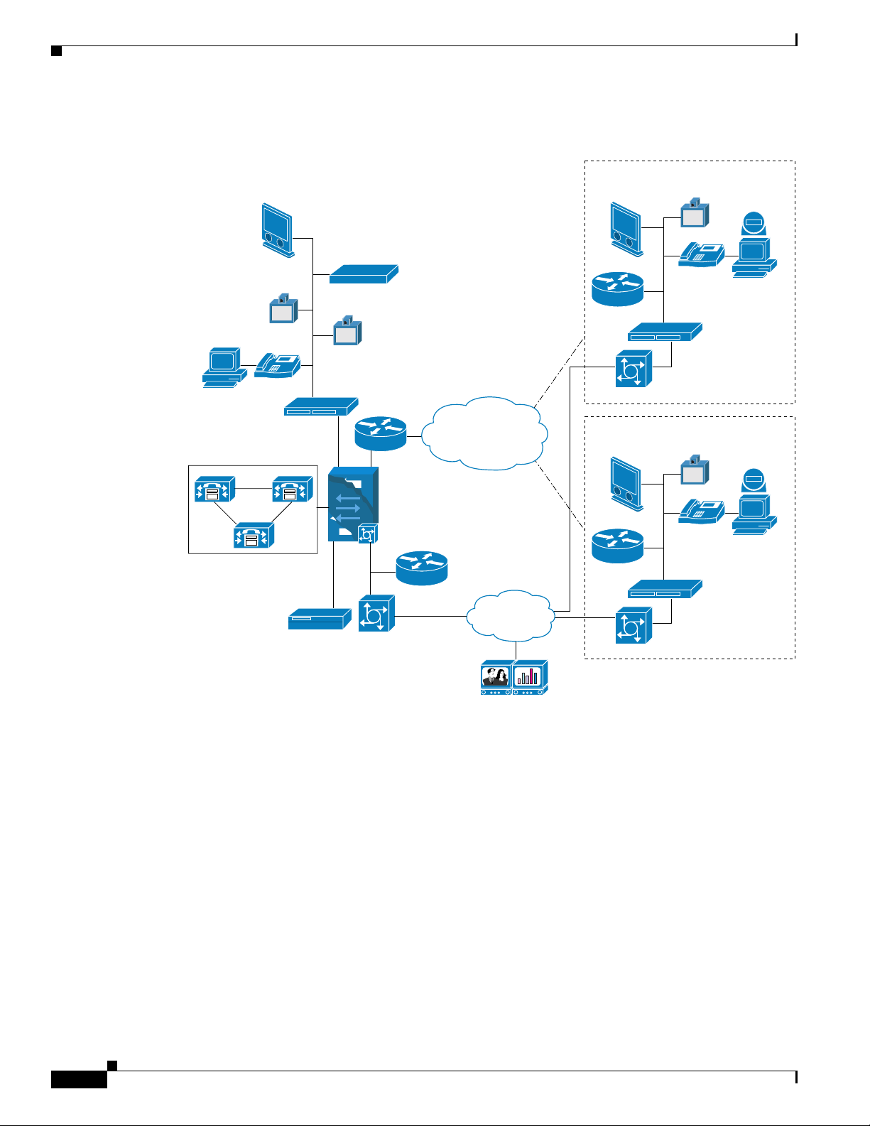
Figure 12-2 shows an example of a multi-site centralized video deployment that uses a Cisco IP Video
Telephony PSTN gateway.
System Test Architecture Reference Manual for IP Telephony
155565
12-3
Page 4
Supported Call Types
Chapter 12 IP Video Telephony Configuration
Figure 12-2 Multi-Site Centralized VIdeo Deployment using Cisco IP Video Telephony PSTN
Gateway
T1000
SCCP controlled
T770 MXP
SCCP controlled
IP
Cisco Unified
Video Advantage
SCCP controlled
Video MCU
H.323 or SCCP controlled
3511 and EMP/3540
T2500
H.323 controlled
T880
H.323 controlled
CAT3524
7206 VXR
CAT6509
V
V
Video PSTN
Gateway
3540/3526
ATM/Frame Relay
Video
Gatekeeper
PRI
or MPLS
PSTN
cloud
PRI
MPLS
E1-E3
ATM Link
T1000
SCCP
controlled
2621XM SRST
2621XM SRST
(MGCP) GW
(MGCP) GW
T1000
SCCP
controlled
2621XM SRST
2621XM SRST
(MGCP) GW
(MGCP) GW
BRI
SCCP controlled
Cisco Unified Video
Advantage SCCP
CAT3524
V
3521 Video BRI GW
for SCCP endpoint
SCCP controlled
Cisco Unified Video
Advantage SCCP
CAT3524
V
3521 Video BRI GW
for SCCP endpoint
T550 MXP
IP
controlled
T550 MXP
IP
controlled
Supported Call Types
The IP Video Telephony deployment supports video calls made between endpoints as shown in
Table 12-2. In this table,
• V = video and audio
• A = audio only
System Test Architecture Reference Manual for IP Telephony
12-4
Tanberg video
conference H.320
T6000
155514
OL-11591-01
Page 5

Chapter 12 IP Video Telephony Configuration
Call Routing
Table 12-2 IP Video Telephony Call Type Matrix
PSTN
Third Party
SCCP
Third
Party
SCCP
Endpoint
Third
Party
H.323
Endpoint
Cisco
Unified
IP Phone
7985
Cisco
Unified
Video
Advantage
SCCP
Audio
Only
SCCP
MCU
Conference
H.323
MCU
Conference
PSTN
Gateways
VVVV AVVAV
Cisco
Unified
VIdeoconferencing
SCCP
Endpoint
Third Party
VVVV AVVAV
H.323
Endpoint
SCCPCisco
VVVV AVVAV
Unified
Video
Advantage
SCCP
AAAA AAAAA
Audio Only
SCCP MCU
VVVV AVVAV
Conference
H.323 MCU
VVVV AVVAV
Conference
1
PSTN
AAAA AAAAA
Gateways
H.225 Trunk VVVV AVVAV
SIP Trunk VVVV AVVAA
1. PSTN = public switched telephone network.
Note Cisco Unified CallManager 5.1 supports security on the Cisco Unified IP Phone 7940G/7941G/7960G/
Call Routing
OL-11591-01
7961G/ 7970G/7971G running SCCP. These phone models also have video capabilities when associated
with Cisco Unified Video Advantage. If two secure video-capable endpoints call each other, the SCCP
signaling and audio media path will be encrypted. Video will work, however signaling and the video
media path to Cisco Unified Video Advantage will not be encrypted.
The IP Video Telephony deployment supports the following call routings. SCCP endpoints include
SCCP Tandberg T1000, and Cisco Unified Video Advantage associated with Cisco IP Phone models
7940G/7960G/7970G. H.323 endpoints include H.323 Tandberg T1000 and Polycom VSX 7000.
• SCCP endpoint > Cisco Unified CallManager > SCCP endpoint
• H.323 endpoint > Gatekeeper > Cisco Unified CallManager > SCCP endpoint
• SCCP endpoint > Cisco Unified CallManager > Gatekeeper > H.323 endpoint
System Test Architecture Reference Manual for IP Telephony
12-5
Page 6

Call Routing
Chapter 12 IP Video Telephony Configuration
• H.323 endpoint > Gatekeeper > Cisco Unified CallManager > Gatekeeper > H.323 endpoint
• SCCP endpoint > Cisco Unified CallManager > Gatekeeper > Cisco Unified CallManager >
Gatekeeper > H.323 endpoint
• SCCP endpoint > Cisco Unified CallManager > SIP trunk> Cisco Unified CallManager >
Gatekeeper > H.323 endpoint
• SCCP endpoint > Cisco Unified CallManager > SIP trunk> Cisco Unified CallManager >
SCCP endpoint
• H.323 endpoint > Gatekeeper > Cisco Unified CallManager > Gatekeeper >
Cisco Unified CallManager > SCCP endpoint
• H.323 endpoint > Gatekeeper > Cisco Unified CallManager > Gatekeeper >
Cisco Unified CallManager > Gatekeeper > H.323 endpoint
• H.323 endpoint > Gatekeeper > Cisco Unified CallManager > SIP Trunk >
Cisco Unified CallManager > Gatekeeper > H.323 endpoint
• SCCP endpoint > Cisco Unified CallManager > Gatekeeper > Cisco Unified CallManager > SCCP
endpoint
• SCCP adhoc or Meet-Me video conferences with these call flows:
–
SCCP endpoint > Cisco Unified CallManager > SCCP MCU
–
SCCP endpoint > Cisco Unified CallManager > Gatekeeper > Cisco Unified CallManager >
SCCP MCU
–
SCCP endpoint > Cisco Unified CallManager > SIP trunk > Cisco Unified CallManager >
SCCP MCU
–
H.323 endpoint > Gatekeeper > Cisco Unified CallManager > SCCP MCU
–
H.323 endpoint > Gatekeeper > Cisco Unified CallManager > Gatekeeper >
Cisco Unified CallManager > SCCP MCU
–
H.323 endpoint > Gatekeeper > Cisco Unified CallManager > SIP trunk >
Cisco Unified CallManager > SCCP MCU
• H.323 adhoc or scheduled video conferences with these call flows:
–
SCCP endpoint > Cisco Unified CallManager > H.323 MCU
–
SCCP endpoint > Cisco Unified CallManager > Gatekeeper > Cisco Unified CallManager >
H.323 MCU
–
SCCP endpoint > Cisco UnifiedCallManager> SIP trunk > Cisco UnifiedCallManager > H.323
MCU
–
H.323 endpoint > Gatekeeper > Cisco Unified CallManager > H.323 MCU
–
H.323 endpoint > Gatekeeper > Cisco Unified CallManager > Gatekeeper >
Cisco Unified CallManager > H.323 MCU
–
H.323 endpoint > Gatekeeper > Cisco Unified CallManager > SIP trunk>
Cisco Unified CallManager > H.323 MCU
• PSTN call with these call flows:
–
SCCP endpoint > Cisco Unified CallManager > Cisco Unified Videoconferencing gateway >
PSTN > Cisco Unified Videoconferencing gateway > Gatekeeper > Cisco Unified CallManager
> SCCP endpoint
12-6
System Test Architecture Reference Manual for IP Telephony
OL-11591-01
Page 7

Chapter 12 IP Video Telephony Configuration
–
SCCP endpoint > Cisco Unified CallManager > Cisco Unified Videoconferencing gateway >
PSTN > Cisco Unified Videoconferencing gateway > Gatekeeper > Cisco Unified CallManager
> H.323 endpoint
–
SCCP endpoint > Cisco Unified CallManager > Cisco Unified Videoconferencing gateway >
PSTN > H.320 endpoint
–
H.323 endpoint > Gatekeeper > Cisco Unified CallManager > Cisco Unified Videoconferencing
gateway > PSTN > H.320 endpoint
–
H.323 endpoint > Gatekeeper > Cisco Unified CallManager > Cisco Unified Videoconferencing
gateway > PSTN > Cisco Unified Videoconferencing gateway > Gatekeeper >
Cisco Unified CallManager > SCCP endpoint
–
H.320 endpoint > Cisco Unified Videoconferencing Gateway > Gatekeeper >
Cisco Unified CallManager > SCCP or H.323 endpoint
The call routing for video calls functions just as the call routing for audio calls. For more information,
refer to the “Understanding Video Telephony” chapter in Cisco Unified CallManager System Guide.
Cisco Unified CallManager supports the Dynamic H.323 Addressing call routing feature. This feature
allowsH.323 endpoints with DHCP addressing to remain registered to a Gatekeeper while Cisco Unified
CallManager controls call routing. For more information, refer to the “Understanding VideoTelephony”
section in Cisco Unified CallManager System Guide. (Table 12-1 provides a link to this document.)
Gatekeeper Configuration for IP Video Telephony
Gatekeeper Configuration for IP Video Telephony
The following sections provide a general description of how gatekeepers were configured for IP Video
Telephony:
• Gatekeeper Configuration Overview, page 12-7
• Gatekeeper Call Routing, page 12-9
Gatekeeper Configuration Overview
Gatekeepers were configured in pairs to create gatekeeper clusters that provide gatekeeper-based Call
Admission Control and call routing redundancy. The endpoints must provide alternate gatekeeper
registration so that the endpoints can utilize both gatekeepers in the cluster.
Three local gatekeeper zones were created, one for Cisco Unified CallManager, one for Cisco Unified
VideoconferencingMCUs,and one for the H.323 endpoints. Zones for Cisco Unified Videoconferencing
MCUs and H.323 endpoints were configured with Invia and Outvia parameters. This configuration
allows gatekeepers to route incoming and outgoing calls to and from these zones to
Cisco Unified CallManager.
The Send Product ID And VersionID Cisco Unified CallManager service parameter must be set to True
to allow the Dynamic H.323 Addressing feature to work and to allow the gatekeeper to route incoming
or outgoing calls to the Cisco Unified CallManager in a given zone.
After the Cisco Unified CallManager service parameter Send Product ID And Version ID is set to True,
the endpoint type of Cisco Unified CallManager H.225 trunks will change to H323-GW.
The following partial output from the Show Gatekeeper Endpoints command shows a single
Cisco Unified CallManager H.225 trunk that is registered to a gatekeeper:
SJC-RFD-GK-1#show gatekeeper endpoints
GATEKEEPER ENDPOINT REGISTRATION
OL-11591-01
System Test Architecture Reference Manual for IP Telephony
12-7
Page 8

Gatekeeper Configuration for IP Video Telephony
CallSignalAddr Port RASSignalAddr Port Zone Name Type Flags
--------------- ----- --------------- ----- --------- ---- -----
0.9.10.5 33209 10.9.10.5 32783 SJC-MP-GK-1 H323-GW
H323-ID: SJC-RFD-MP-1-CM1_2_3
Voice Capacity Max.= Avail.= Current.= 0
Zone prefixes were configured in the Cisco Unified CallManager zone for intercluster call flows. This
configuration is required for intercluster gatekeeper-controlled call routing. The other two zones do not
require a local zone prefix to be configured. The endpoints and MCUs are directed to these zones by the
Zone Subnet command in the gatekeeper configuration.
The Cisco Unified CallManager cluster uses the default technology prefix 1#* to register its
gatekeeper-controlled intercluster trunks in the Cisco Unified CallManager zone. Then,
Cisco Unified CallManager cluster registers a dedicated H.225 gatekeeper-controlled trunk to the MCU
zone. The trunk and the MCU zone are used for invites initiated from the MCU Conference control web
pages. Finally, the Cisco Unified CallManager cluster registers a special trunk called RasAggregator to
the H.323 endpoints zone. This trunk is dynamically created and registered as a result of the H.323
endpoints device pool configuration in Cisco Unified CallManager.
The following partial output from the Show Gatekeeper Endpoints command shows a single
Cisco Unified CallManager RasAggregator trunk that is registered to a gatekeeper:
SJC-RFD-GK-1#show gatekeeper endpoints
CallSignalAddr Port RASSignalAddr Port Zone Name Type
--------------- ----- --------------- ----- --------- ----
10.9.10.5 33206 10.9.10.5 32783 SJC-VIDEO-GK-1 H323-GW
H323-ID: RasAggregator_1#*_SJC-VIDEO-GK-1_3
Voice Capacity Max.= Avail.= Current.= 0
Chapter 12 IP Video Telephony Configuration
================================
GATEKEEPER ENDPOINT REGISTRATION
================================
A single RasAggregator trunk was created for all gatekeeper-controlled H.323 endpoints that share the
same gatekeeper zone and Cisco UnifiedCallManager group. All gatekeeper-controlledH.323 endpoints
within the same gatekeeper endpoint zone must be configured as part of the same Cisco Unified
CallManager group and device pool, otherwise Cisco Unified CallManager will register multiple
RasAggregator trunks to a single gatekeeper endpoint zone. In this situation, some incoming calls from
the H.323 endpoints will fail.
Note This configuration prevents gatekeeper-controlled H.323 endpoints from being load balanced across
multiple Cisco Unified CallManager servers by using device pools and Cisco Unified CallManager
groups. One way to accomplish such load balancing is to create multiple gatekeeper zones dedicated to
H.323 endpoints for each device pool or Cisco Unified CallManager group.
For an example of a video gatekeeper configuration, see the >>>>>>>
12-8
System Test Architecture Reference Manual for IP Telephony
OL-11591-01
Page 9

Chapter 12 IP Video Telephony Configuration
Gatekeeper Call Routing
Calls are routed through the gatekeeper as follows:
• Inbound call to Cisco Unified CallManager zone from other gatekeepers—Routed to the registered
Cisco Unified CallManager Gatekeeper-controlled H.225 intercluster trunks within the Cisco
Unified CallManager zone in a Round Robin distribution algorithm using the Default Technology
prefix.
• Outbound call from Cisco Unified CallManager zone to other gatekeepers—Normal gatekeeper call
routing using location request.
• Inbound Call to MCU zone from other gatekeepers—Routed out to the registered Cisco Unified
CallManager gatekeeper-controlled H.225 intercluster trunks within the Cisco UnifiedCallManager
zone in a round robin distribution algorithm using the Default Technology prefix. Then routed by
Cisco Unified CallManager directly to the MCU via its H.323 gateway.
• Outbound call from MCU—Routed to Cisco Unified CallManager via the MCU dedicated H.225
gatekeeper-controlled trunks that are registered to the MCU zone.
• Outbound call from H.323 endpoints—Routed to Cisco Unified CallManager via RasAggregator
H.225 trunk.
• Inbound call from other Gatekeepers to H.323 endpoints—Call is first routed out the Registered
Cisco Unified CallManager gatekeeper-controlled H.225 trunk within the Cisco Unified
CallManager zone in a round robin distribution algorithm using the Default Technology prefix. It is
then routed back to the gatekeeper video endpoint zone via the RasAggregator trunk.
• Inbound call from MCUs to H.323 endpoints—Call is first routed to Cisco Unified CallManager via
the MCU dedicated H.225 gatekeeper-controlled trunks that are registered to the MCU zone. It is
then routed back to the Gatekeeper Video endpoint zone via the RasAggregator trunk.
• Inbound call from Cisco Unified Videoconferencing gateway—Call is routed to the registered
Cisco Unified CallManager gatekeeper. The gatekeeper receives an admission request from the
Cisco Unified Videoconferencinggateway, and the gatekeeper replies with an admission confirm to
send the call to Cisco Unified CallManager via the RasAggregator trunk.
Cisco Unified Videoconferencing 3540 MCU Conference Bridge Configuration for IP Video Telephony
Cisco Unified Videoconferencing 3540 MCU Conference Bridge
Configuration for IP Video Telephony
This section provides basic information about configuring the Cisco Unified Videoconferencing 3540
for IP video telephony.
For related information, refer to Administrator's Guide for Cisco Unified Videoconferencing 3511 MCU
and Cisco Unified Videoconferencing 3540 MCU Module Releases, which are available at this URL:
http://www.cisco.com/en/US/products/hw/video/ps1870/prod_maintenance_guides_list.html
The Very Large Campus Clustering over the WAN deployment model consisted of these components:
• 3544 Cisco Unified Videoconferencing chassis
• Cisco Unified Videoconferencing 3544 System 100-port MCU module
• EMP3 board
System Test Architecture Reference Manual for IP Telephony
OL-11591-01
12-9
Page 10

Cisco Unified Videoconferencing 3540 MCU Conference Bridge Configuration for IP Video Telephony
In addition, these components were tested in the Large Multi-Site Centralized with SRST site model for
EUEM:
• 3544 Cisco Unified Videoconferencing chassis
–
Cisco Unified Videoconferencing 3544 System 60-port MCU module
–
EMP3 board
• 3511 MCU with integrated EMP
The configuration of the 3511 is are similar to the 3540 MCU configuration that this section describes.
Half of the Cisco Unified Videoconferencing-3540-MC10A MCU ports were configured to register as a
SCCP Cisco video conference bridge (Cisco Unified Videoconferencing-35xx) device and were
registered with Cisco Unified CallManager. The remaining ports were deployed as H.323 video
conference resources and registered to the gatekeeper cluster in the MCU zone.
When deployed in a Cisco Unified CallManager SCCP environment, the primary function of the
Cisco Unified VideoconferencingMCU is to provide media processing for conferences. In this capacity,
the Cisco Unified Videoconferencing MCU negotiates parameters with the terminals participating in a
conference, and it provides media processing. Cisco Unified CallManager manages the call flow.
Terminals use Cisco Unified CallManager processes to initiate conferences, and
Cisco Unified CallManager manages the allocation of Cisco Unified Videoconferencing MCU
resources.
When deployed in an H.323 environment, the Cisco Unified Videoconferencing MCU manages its own
resources and provides media processing. Calls are initiated using the processes that the Cisco Unified
Videoconferencing MCU uses for H.323 terminals. In this scenario, you must configure Cisco Unified
CallManager to communicate with an H.323 gatekeeper for inbound calls from the MCU. For outbound
calls, you must configure in Cisco Unified CallManager an H.323 gateway with the MCU IP address as
the device name. This arrangement allows SCCP terminals to participate in conferences that include
other SCCP terminals, H.323 terminals, or terminals of both types.
The following tables show how the Cisco Unified Videoconferencing 3540 MCU was configured using
the Cisco Unified Videoconferencing Administrator web page. Fields not shown in these tables were set
to their default values.
• Table 12-3—IP/VC Board > Basics
• Table 12-4—IP/VC Board > Addressing
• Table 12-5—IP/VC MCU > Settings > Basics
• Table 12-6—IP/VC MCU > Protocols > H.323 Protocol Configuration
• Table 12-7—IP/VC MCU > IP/VC MCU > Protocols > H.323Protocol Configuration > Advanced
Gatekeeper Settings
• Table 12-8—IP/VC MCU > Protocols > SCCP Protocol Configuration
Chapter 12 IP Video Telephony Configuration
12-10
Table 12-3 Cisco Unified Videoconferencing MCU Configuration: IP/VC Board > Basics
Field Setting
Board name MC10A
Location Appropriate value
Serial number Appropriate value
Hardware version Appropriate value
Date/Time Appropriate value
System Test Architecture Reference Manual for IP Telephony
OL-11591-01
Page 11

Chapter 12 IP Video Telephony Configuration
Table 12-3 Cisco Unified Videoconferencing MCU Configuration: IP/VC Board > Basics
Field Setting
Slot number Appropriate value
Software version 4.2.10
Table 12-4 Cisco Unified Videoconferencing MCU Configuration: IP/VC Board > Addressing
Field Setting
IP Address Appropriate value
Subnet Mask Appropriate value
Router IP Appropriate value
DNS Suffix XX.com
Preferred DNS server Appropriate value
Alternate DNS server Appropriate value
Port type Ethernet-CSMA/CD
MAC Address Appropriate value
Port settings 100/Mbps / Full Duplex
Port status 100/Mbps / Full Duplex
Cisco Unified Videoconferencing 3540 MCU Conference Bridge Configuration for IP Video Telephony
Table 12-5 Cisco Unified Videoconferencing MCU Configuration: IP/VC MCU > Settings > Basics
Field Setting
MCU Mode MCU
Number of SCCP ports 30
Table 12-6 Cisco Unified Videoconferencing MCU Configuration: IP/VC MCU > Protocols > H.323
Protocol Configuration
Field Setting
Activate protocol settings Checked
Description H.323 Protocol Configuration
Registration Name SJC-RFD-MCU-1
Gatekeeper Address 10.9.12.99
Gatekeeper Port 1719
Strip zone prefix Unchecked
Enable H.329 Unchecked
Enable Fast Start Unchecked
Enable generic audio capabilities Unchecked
OL-11591-01
System Test Architecture Reference Manual for IP Telephony
12-11
Page 12

Cisco Unified Videoconferencing 3540 MCU Conference Bridge Configuration for IP Video Telephony
Table 12-6 Cisco Unified Videoconferencing MCU Configuration: IP/VC MCU > Protocols > H.323
Protocol Configuration (continued)
Field Setting
Enable alternate Gatekeeper Unchecked
Enable H.245 tunneling Unchecked
Table 12-7 Cisco Unified Videoconferencing MCU Configuration: IP/VC MCU > Protocols > H.323
Protocol Configuration > Advanced Gatekeeper Settings
Field Setting
MCU Registration Mode MCU
Note The configuration shown in Table 12-7 directly affects gatekeeper call routing. If MCU Registration
Mode is not set to MCU and instead left at its default setting of Gateway, gatekeeper call routing may
not function in the Very Large Campus Clustering over the WAN deployment model.
Chapter 12 IP Video Telephony Configuration
.
Table 12-8 Cisco Unified Videoconferencing MCU Configuration: IP/VC MCU > Protocols > SCCP
Protocol Configuration
Field Setting
TFTP Servers: IP Address / Port Appropriate values
CallManagers: IP Address / Port Appropriate values
Perform MCU reset on CallManager Reset
Checked
message
Local port base 11000
Priority 24
Registration: Retries 3
Initial timeout 30
Consequent timeout 10
Keep Alive: Retries 3
Timeout 10
Recovery mode Not applicable
Change configuration locally Unchecked
To create the Cisco Unified CallManager dedicated H.323 service on the MCU, information was copied
from the existing default service prefix 87 named Continuous Presence (MP). The only change made to
this default service prefix was to change the prefix to 25. This prefix must be used when configuring
Cisco Unified CallManager route patterns, as described in the “Route Pattern Configuration for MCU
Service” section on page 12-25.
12-12
System Test Architecture Reference Manual for IP Telephony
OL-11591-01
Page 13

Chapter 12 IP Video Telephony Configuration
Cisco Unified Videoconferencing Gateway Configuration for Video PSTN Gateway
Cisco Unified Videoconferencing Gateway Configuration for
Video PSTN Gateway
This section provides information about configuring a Cisco Unified Videoconferencing gateway for a
video PSTN gateway.
For related information, refer to this URL:
http://www.cisco.com/univercd/cc/td/doc/product/ipvc/ipvcgw/index.htm
The following tables show how the 2 PRI port version of the Cisco Unified Videoconferencing 3544
System Gateway module was configuredusing the Cisco Unified Videoconferencing Administrator web
page. Fields not shown in these tables were set to their default values.
• Table 12-9—IPVC/3540 GW > Board > Basics
• Table 12-10—IPVC/3540 GW > Board > Addressing
• Table 12-11—IPVC/3540 GW > Settings > Basics
• Table 12-12—IPVC/3540 GW > Settings > IP Connectivity
• Table 12-13—IIPVC/3540 GW > Settings > Media Modes
• Table 12-14—IIPVC/3540 GW > Settings > Bonding
• Table 12-15—IPVC/3540 GW > Services > Voice
• Table 12-16—IPVC/3540 GW > Services > Video
• Table 12-17—IPVC/3540 GW > PRI > Port 1 Basics
• Table 12-18—IPVC/3540 GW > PRI Port 1 Physical Interface
Table 12-9 Cisco Unified Videoconferencing MCU Configuration: IPVC/3540 GW > Board >
Basics
Field Setting
Model number IPVC-3540-GW2P
Location Appropriate value
Serial number Appropriate value
Hardware version Appropriate value
Date/Time Appropriate value
Slot number Appropriate value
Software version 4.0.40
Table 12-10 Cisco Unified Videoconferencing MCU Configuration: IPVC/3540 GW > Board >
Addressing
Field Setting
IP Address Appropriate value
Subnet Mask Appropriate value
Router IP Appropriate value
DNS server IP Appropriate value
OL-11591-01
System Test Architecture Reference Manual for IP Telephony
12-13
Page 14

Cisco Unified Videoconferencing Gateway Configuration for Video PSTN Gateway
Table 12-10 Cisco Unified Videoconferencing MCU Configuration: IPVC/3540 GW > Board >
Addressing (continued)
Field Setting
Device DNS name Appropriate value
Port type Ethernet-CSMA/CD
MAC address Appropriate value
Port settings 100/Mbps / Full Duplex
Port status 100/Mbps / Full Duplex
Table 12-11 Cisco Unified Videoconferencing MCU Configuration: IPVC/3540 GW > Settings >
Basics
Field Setting
Gateway Identifier Appropriate value
Chapter 12 IP Video Telephony Configuration
Table 12-12 Cisco Unified Videoconferencing MCU Configuration: IPVC/3540 GW > Settings >
IP Connectivity
Field Setting
IP connectivity mode Using gatekeeper
Specify gatekeeper address Selected
Gatekeeper address Appropriate value
Gatekeeper port Appropriate value
Gateway registration mode Version 2
Table 12-13 Cisco Unified Videoconferencing MCU Configuration: PVC/3540 GW > Settings >
Media Modes
Field Setting
Enable G722 Checked
Enable G722.1 Unchecked
Enable G728 Checked
Enable H263 Checked
Enable H263+ Unchecked
Enable H264 Checked
Enable T120 Checked
Enable FECC Checked
12-14
System Test Architecture Reference Manual for IP Telephony
OL-11591-01
Page 15

Chapter 12 IP Video Telephony Configuration
Table 12-14 Cisco Unified Videoconferencing MCU Configuration: PVC/3540 GW > Settings >
Field Setting
Enable bonding Checked
Maximum B channels for a bonded call Appropriate value
For bonded calls, allow downspeeding down to x
calls
Cisco Unified Videoconferencing Gateway Configuration for Video PSTN Gateway
Bonding
Appropriate value
.
Table 12-15 Cisco Unified Videoconferencing MCU Configuration: PVC/3540 GW > Services >
Voice
Field Setting
Prefix 9
Description Voice call
Call type Voice
Bit rate 64
PRI port 1 Enabled
PRI port 2 Enabled
.
Table 12-16 Cisco Unified Videoconferencing MCU Configuration: PVC/3540 GW > Services >
Video
Field Setting
Prefix 79
Description Video call bonding 6*64
Call type Voice
Bit rate 384
PRI port 1 Enabled
PRI port 2 Enabled
.
OL-11591-01
Table 12-17 Cisco Unified Videoconferencing MCU Configuration: PVC/3540 GW > PRI Port 1 >
Basics
Field Setting
Port enable Checked
Post phones number range 01917400000 to 01917400029
Local area 0191740
Strip Local Area Code Checked
System Test Architecture Reference Manual for IP Telephony
12-15
Page 16

Chapter 12 IP Video Telephony Configuration
Cisco Unified CallManager Configuration for IP Video Telephony
Table 12-18 Cisco Unified Videoconferencing MCU Configuration: PVC/3540 GW > PRI Port 1 >
Physical Interface
Field Setting
Interface E1/T1
Country Appropriate value
Network access Appropriate value
Signaling protocol Appropriate value
Cisco Unified CallManager Configuration for IP Video
Telephony
The following sections provide an overview of how Cisco Unified CallManager was configured for IP
Video telephony testing. For additional information about how Cisco Unified CallManager was
configured for Cisco IP Communications Release 5.1(1) testing, see Chapter 2, “Cisco Unified
CallManager Configuration.”
• Cisco Unified CallManager Configuration Overview, page 12-17
• Region Configuration in Cisco Unified CallManager, page 12-17
• Video Deployment with RSVP, page 12-21
• Gatekeeper Configuration in Cisco Unified CallManager, page 12-23
• MCU Configuration in Cisco Unified CallManager, page 12-23
• Route Pattern Configuration for MCU Service, page 12-25
• Cisco Unified Videoconferencing PSTN Gateway Configuration for Cisco Unified CallManager,
page 12-25
12-16
System Test Architecture Reference Manual for IP Telephony
OL-11591-01
Page 17

Chapter 12 IP Video Telephony Configuration
Cisco Unified CallManager Configuration for IP Video Telephony
Cisco Unified CallManager Configuration Overview
The following table provides an overview of how to configure Cisco Unified CallManager for IP Video
telephony.
Procedure Reference
Step 1
Step 2
Step 3
Step 4
If you are not using a single Region for all call
types, configure Regions.
If you use locations for call admission control,
configure locations for video call bandwidth.
To use a Cisco video conference bridge, configure
the appropriate conference bridge for your
network.
To configure a user to use the video conference
bridge instead of other conference bridges,
configure the media resource groups and media
resource group lists for the user.
• Refer to the “Region Configuration” chapter
inCisco Unified CallManagerAdministration
Guide.
• Refer to the “Call Admission Control”
chapterin Cisco Unified CallManagerSystem
Guide.
• Refer to the “Location Configuration”chapter
inCisco Unified CallManagerAdministration
Guide.
• Refer to the “Call Admission Control”
chapterin Cisco Unified CallManagerSystem
Guide.
• Refer to the “Conference Bridge
Configuration” chapter in
Cisco Unified CallManager Administration
Guide.
• Refer to the “Media Resource Group
Configuration” chapter in
Cisco Unified CallManager Administration
Guide.
• Refer to the “Media Resource Group List
Configuration” chapter in
Cisco Unified CallManager Administration
Guide.
Region Configuration in Cisco Unified CallManager
This section provides an overview of how regions were configured in the Very Large Campus Clustering
over the WAN deployment model. These configurations were made in Cisco Unified CallManager
Administration.
For additional information about regions, refer to IP Video Telephony Solution Reference Network
Design (SRND) for Cisco Unified CallManager. (Table 12-1 provides a link to this document.)
The total bitrate for the video bandwidth of the region should be set to accommodate the total bitrate of
the video and audio RTP streams used in video calls.
Table 12-19 shows the regions matrix that was created in Cisco Unified CallManager.
System Test Architecture Reference Manual for IP Telephony
OL-11591-01
12-17
Page 18

Cisco Unified CallManager Configuration for IP Video Telephony
Table 12-19 Regions Matrix
Default SIP SJC-Local Video WAN
Default G.711/384 G.711/None G.711/384 G.711/384 G.711/384
SIP G.711/None G.711/None G.711/None G711/None G.711/None
SJC-Local G.711/384 G.711/None G.711/384 G.711/384 G.729/384
Video G.711/384 G.711/None G.711/384 G.711/384 G.711/384
WAN G.711/384 G.711/None G.711/384 G.711/384 G.711/384
The following devices were assigned to the regions shown:
• SJC-Local region—Includes all phones without video capabilities, CTI ports, voice mail ports,
conference bridges, transcoders, and PSTN gateways without video capabilities.
• SIP region—Includes SIP trunks to Cisco Unified CallManager 4.(x).
• Videoregion—Toprovide the maximum level of interoperability and features, these video endpoints
have been assigned to this region:
–
Cisco Unified Video Advantage associated with Cisco Unified IP Phone
7940G/7941G/7960G/7961G/ 7970G/7971G running SCCP.
–
Cisco Unified IP Phone 7985
–
Polycom H.323 video endpoints. (The Polycom VSX 7000 with firmwareversion 8.0.3 supports
G.722, G.722.1, G.711, G.728, audio codecs.)
–
SCCP Tandberg T1000 video endpoints.
–
SCCP Tandberg MXP video endpoints.
–
H.323 Tandberg 990 MXP video endpoints
–
Cisco Unified Videoconferencing 3540 MCU SCCP Video Conference Bridge.
–
Cisco Unified Videoconferencing 3540 MCU H.323 Gateway.
• WAN region—Includes H.225 intercluster trunks and SIP trunks to other cluster.
Chapter 12 IP Video Telephony Configuration
Note For additional information about codecs support by endpoints, refer to the “Endpoints” section
in IP Video Telephony Solution Reference Network Design (SRND) for
Cisco Unified CallManager. ( Table 12-1 provides a link to this document.)
H.245 Capabilities Exchange with Intercluster Trunks
The codec specified for a region is the maximum codec that will be exchanged during an intercluster
trunk call. For example, the Cisco Unified IP Phone 7960G supports G.729, G.711, and Cisco wideband
audio codec. If audio codec between two regions is configured for G.711, Cisco Unified CallManager
will advertise G.711 and G.729, not G.711 only. If audio codec between two regions is configured for
G.729, Cisco Unified CallManager will advertise only G.729 because the phone does not support a lower
bandwidth codec.
System Test Architecture Reference Manual for IP Telephony
12-18
OL-11591-01
Page 19

Chapter 12 IP Video Telephony Configuration
SIP Trunk Calls with Asymmetric Regions
This section provides an overview of two asymmetric regions scenarios for intercluster calls across SIP
trunks.
Scenario 1—Device with an associated Cisco Unified Video Advantage in Region A calls a device in Region D
through an intercluster trunk
In this scenario, a call proceeds as follows:
Region A – SJC Cisco Unified CallManager – Region B – SIP trunk – Region C – DFW
Cisco Unified CallManager – Region D
The regions include the following devices:
• Region A (Video)—All video enabled phones, including Cisco Unified Video Advantage
• Region B (SJC-WAN)—All intercluster trunks
• Region C (DFW-WAN)—All intercluster trunks
• Region D (SJC-Local)—All devices without video capabilities
Table 12-20 shows the regions matrix for SJC.
Cisco Unified CallManager Configuration for IP Video Telephony
Table 12-20 SJC Regions Matrix
Region A Region B
Region A G.711/384 G.711/384
Region B G.711/384 G.729/384
Table 12-21 shows the regions matrix for DFW.
Table 12-21 DFW Regions Matrix
Region C Region D
Region C G.729/384 G.729/384
Region D G.729/384 G.711/384
When a device with an associated Cisco Unified Video Advantage in Region A calls through an
intercluster trunk in Region B, G.729 and G.711 codecs are sent from SJC to DFW during the
capabilities exchange process.
The call will arrive at DFW through an intercluster trunk in Region C and will then be routed to a device
in Region D. Only the G.729 codec will be sent from DFW to SJC during the capabilities exchange
process.
After the capabilities exchange process completes, the call will connect using the G.729 codec.
OL-11591-01
Scenario 2—H.323 video endpoint with only G.711 capabilities in Region A calls a device in Region E through an
SIP trunk
In this scenario, a call proceeds as follows:
Region A – SJC Cisco Unified CallManager – Region B – Transcoder – Region C – Intercluster trunk –
Region D – DFW Cisco Unified CallManager – Region E
System Test Architecture Reference Manual for IP Telephony
12-19
Page 20

Cisco Unified CallManager Configuration for IP Video Telephony
The regions include the following devices:
• Region A (Video)—All video enabled phones, including Cisco Unified Video Advantage
• Region B (SJC-Local)—All devices without video capabilities
• Region C (SJC-WAN)—All intercluster trunks
• Region D (DFW-WAN)—All intercluster trunks
• Region E (DFW-Local)—All devices without video capabilities
Table 12-22 shows the regions matrix for SJC.
Table 12-22 SJC Regions Matrix
Region A Region B Region C
Region A G.711/384 G.711/384 G.711/384
Region B G.711/384 G.711/384 G.729/384
Region C G.711/384 G.729/384 G.729/384
Table 12-23 shows the regions matrix for DFW.
Chapter 12 IP Video Telephony Configuration
Table 12-23 DFW Regions Matrix
Region D G.729/384 G.729/384
Region E G.729/384 G.711/384
When an H.323 video endpoint in Region A calls through an intercluster trunk in Region B, only the
G.711 codec is sent from SJC to DFW during the capabilities exchange process.
The call will arrive at DFW through an intercluster trunk in Region C and will then be routed to a device
in Region D. Only the G.729 codec will be sent from DFW to SJC during the capabilities exchange
process.
After the capabilities exchange process completes, the call will connect using the G.729 codec.
The Cisco Unified CallManager at SJC will invoke a transcoder between the H.323 video device and the
intercluster trunk. The transcoder will transcode the call between the G.729 and the G.711 codecs.
Transcoders and Call Transfer
This section provides an overview of a call-transfer scenario that involves a legacy transcoder.
Note Cisco legacy transcoders (6608, CMM ACT, NM-HDV) currently do not support video pass-through. If
a video call is sent through a transcoder, the call will become an audio-only call.
Region D Region E
12-20
Before the call is transferred in this scenario, it proceeds as described for Scenario 2 in the “SIP Trunk
Calls with Asymmetric Regions” section on page 12-19. That is, an H.323 video endpoint with only
G.711 capabilities in Region A calls a device in Region E through an intercluster trunk.
After the call is established, it is transferred by the device in Region E to a local video endpoint in Region
F In this call-forward scenario, the call proceeds as follows:
System Test Architecture Reference Manual for IP Telephony
OL-11591-01
Page 21

Chapter 12 IP Video Telephony Configuration
Region A – SJC Cisco Unified CallManager – Region B – Transcoder – Region C – Intercluster trunk –
Region D – transcoder – Region E – DFW Cisco Unified CallManager – Region F
The regions include the following devices:
• Region A (SJC-Video)—All video enabled phones, including Cisco Unified Video Advantage
• Region B (SJC-Local)—All devices without video capabilities
• Region C (SJC-WAN)—All intercluster trunks
• Region D (DFW-WAN)—All intercluster trunks
• Region E (DFW-Local)—All devices without video capabilities
• Region F (DFW-Video)—All video enabled phones, including Cisco Unified Video Advantage
Table 12-24 shows the regions matrix for SJC.
Table 12-24 SJC Regions Matrix
Region A G.711/384 G.711/384 G.711/384
Region B G.711/384 G.711/384 G.729/384
Region C G.711/384 G.729/384 G.729/384
Cisco Unified CallManager Configuration for IP Video Telephony
Region A Region B Region C
Table 12-25 shows the regions matrix for DFW.
Table 12-25 DFW Regions Matrix
Region D G.729/384 G.729/384 G.711/384
Region E G.729/384 G.711/384 G.711/384
Region F G.711/384 G.711/384 G.711/384
If the H.323 video endpoint in SJC called directly to an H.323 video endpoint in DFW, a transcoder
would not be invoked and video would be available for the call. However, in this scenario, a transcoder
is invoked before the call is transferred. Therefore, video is not available after the call transferred.
Note This transfer scenario applies to all calls transferred via Cisco Unity Automated Attendant and via
Cisco IPCC Express.
Video Deployment with RSVP
You can use Cisco RSVP Agent to control video bandwidth. Such a deployment could be use in a
situation where an audio device can use only G.711 and audio transcoding is necessary.
Cisco RSVP Agent is an IOS-based RSVP proxy with an SCCP interface and is the only method for
performing audio transforming of a video call. Cisco RSVP Agent registers to Cisco Unified
CallManager through SCCP as an MTP or transcoder.Videoendpoints do not need to support RSVP, but
they do need to be allocated a media resource group that contains a Cisco RSVP agent. When RSVP or
audio transcoding is required, Cisco Unified CallManager inserts a Cisco RSVP Agent in the call to
perform RSVP reservation or transcoding.
Region D Region E Region F
OL-11591-01
System Test Architecture Reference Manual for IP Telephony
12-21
Page 22

Cisco Unified CallManager Configuration for IP Video Telephony
In addition to Cisco RSVP Agent, you can use Cisco Unified CallManager region and location settings
to establish video bandwidth for a call. However,with the introduction of RSVP agent in video call, the
following rule is required to establish the bandwidth for a video call:
end-to-end video region = minimum of (region (A,agentA), region(agentA,agentB),
region(agentB,B) and region(A,B) )
Figure 12-3 shows a basic video deployment using Cisco RSVP Agent.
Figure 12-3 Basic Video Deployment with Cisco RSVP Agent
Chapter 12 IP Video Telephony Configuration
Cisco Unified CallManager
Location A
Cisco RSVP
Agent A
Location B
Cisco RSVP
Agent B
RSVP/RTP
SCCP
Phone
H.323
Video
Phone
SIP
Phone
SIP
Phone
H.323
Video
Phone
SCCP
Phone
SCCP
SIP
155487
RTP
H.323
The following configuration was used for the Cisco RSVP Agent. The codec pass-through allows the
audio transcoding of a video call:
dspfarm profile 2 transcode
codec pass-through
codec gsmfr
codec g729ar8
codec g729abr8
codec g711ulaw
codec g711alaw
rsvp
maximum sessions 8
associate application SCCP
12-22
The following command confirms that the Cisco RSVP Agent is configured properly:
SCCP Admin State: UP
User Masked Codec list: None
Call Manager: 10.10.110.11, Port Number: 2000
Priority: 1, Version: 5.0.1, Identifier: 1
Transcoding Oper State: ACTIVE - Cause Code: NONE
Active Call Manager: 10.10.110.11, Port Number: 2000
TCP Link Status: CONNECTED, Profile Identifier: 2
Reported Max Streams: 16, Reported Max OOS Streams: 0
Supported Codec: pass-thru, Maximum Packetization Period: N/A
Supported Codec: gsmfr, Maximum Packetization Period: 20
Supported Codec: g729ar8, Maximum Packetization Period: 60
Supported Codec: g729abr8, Maximum Packetization Period: 60
System Test Architecture Reference Manual for IP Telephony
OL-11591-01
Page 23

Chapter 12 IP Video Telephony Configuration
Cisco Unified CallManager Configuration for IP Video Telephony
Supported Codec: g711ulaw, Maximum Packetization Period: 30
Supported Codec: g711alaw, Maximum Packetization Period: 30
RSVP : ENABLED
Gatekeeper Configuration in Cisco Unified CallManager
This section describes how gatekeepers were configured for video endpoints in Cisco Unified
CallManager Administration.
For additional information, refer to the “Gatekeeper Configuration” chapter in Cisco Unified
CallManager Administration Guide.
To access the Cisco Unified CallManager Administration web pages for adding and configuring
gatekeepers, choose Device > Gatekeeper from the Cisco Unified CallManager Administration
application.
Table 12-26 shows how one of the gatekeepers was configuredin the Very LargeCampus Clustering over
the WAN deployment model.
Table 12-26 Gatekeeper Configuration
Field Setting
Host Name/IP Address Host Name/IP Address
Description SJC-RFD-GK-1
Registration Request Time To Live 60
Registration Retry Timeout 300
Enable Device Checked
1. Only the primary gatekeeper address in a cluster is required.
MCU Configuration in Cisco Unified CallManager
The following sections describe how Cisco Unified CallManager was configured with the Cisco Unified
Videoconferencing 3540 MCU. This MCU registers with Cisco Unified CallManager as a video
conference bridge. It also functions as a stand-alone H.323 video conferencing resource.
• SCCP Video Conference Bridge
• H.323 Video Conference Bridge
For additional information, refer to the “Conference Bridges” chapter in Cisco Unified CallManager
System Guide. (Table 12-1 provides a link to this document.)
SCCP Video Conference Bridge
1
OL-11591-01
To access the Cisco Unified CallManager Administration web pages for adding and configuring video
endpoints, choose Media Resources > Conference Bridge from the Cisco Unified CallManager
Administration application.
Table 12-27 shows how the video conference bridge was configured in the Very Large Campus
Clustering over the WAN deployment model. Fields not shown in this table were set to their default
values.
System Test Architecture Reference Manual for IP Telephony
12-23
Page 24

Cisco Unified CallManager Configuration for IP Video Telephony
Table 12-27 MCU SCCP Video Conference Bridge Configuration
Field Setting
Conference Bridge Type Cisco Video Conference Bridge (Cisco Unified
MAC Address 0003D60028CE
Description VCB0003D60028CE
Device Pool DP-Video
Location SJC
After this video conference bridge was added to Cisco Unified CallManager, it was added to a media
resource group. This media resource group was then added to a media resource group list, which was
assigned to all video-enabled phones.
For additional information, refer to the “Media Resource Management” chapter in Cisco Unified
CallManager System Guide. (Table 12-1 provides a link to this document.)
Chapter 12 IP Video Telephony Configuration
Videoconferencing-35xx)
H.323 Video Conference Bridge
An H.323 gateway was created to allow Cisco Unified CallManager to route calls to the H.323 video
conference bridge.
To access the Cisco Unified CallManager Administration web pages for adding and configuring
gateways, choose Device > Gateway from the Cisco Unified CallManager Administration application.
Table 12-28 shows how the MCU H.323 gateway was configured in the Very Large Campus Clustering
over the WAN deployment model Fields not shown in this table were set to their default values.
Table 12-28 MCU H.323 Gateway Configuration
Field Setting
Device Name 10.9.14.14
Description SJC-RFD-MCU-1
Device Pool DP-Video
Call Classification OnNet
Media Resource Group List MRGL_SJC_VIDEO
Location SJC
AAR Group SJC
Signaling Port 2720
Media Termination Point Required Unchecked
Retry Video Call as Audio Checked
Wait for Far End H.245 Terminal Capability Set Checked
Multilevel Precedence and Preemption (MLPP)
Information
Significant Digits All
Calling Search Space SJC_CSS
Not applicable
12-24
System Test Architecture Reference Manual for IP Telephony
OL-11591-01
Page 25

Chapter 12 IP Video Telephony Configuration
Table 12-28 MCU H.323 Gateway Configuration (continued)
Field Setting
AAR Calling Search Space SJC_CSS
Prefix DN blank
Redirecting Number IE Delivery – Inbound Uncheked
Enable Inbound FastStart Uncheked
Route Pattern Configuration for MCU Service
Cisco Unified CallManager routes outbound calls to the MCU via this H.323 gateway utilizing a route
pattern. In Very Large Campus Clustering over the WAN deployment model this route pattern was
21XXX.
Note The route pattern must begin with the same digits as the service prefix configured on the Cisco Unified
Videoconferencing 3540 MCU.
Cisco Unified CallManager Configuration for IP Video Telephony
Cisco Unified Videoconferencing PSTN Gateway Configuration for
Cisco Unified CallManager
These sections describe how the PSTN gateway was configured for Cisco Unified Videoconferencing:
• Video PSTN Gateway, page 12-25
• Route Pattern Configuration for Cisco Unified Videoconferencing PSTN Gateways, page 12-26
Video PSTN Gateway
A Cisco Unified Videoconferencing gateway registers as a gateway on Cisco Unified CallManager, and
it uses a specific signaling port. Table 12-29 lists the signaling port for each type of MCU and gateway.
Note If you want to use the 1720 standard value for the signaling port on Cisco Call Manager configuration,
you can change this value for Cisco Unified Videoconferencing devices.
Table 12-29 Cisco Unified Videoconferencing MCU and Gateway Signaling Ports
MCU and Gateway Type Default Signaling Port
3540 1820
3526 1820
3521 1920
3511 2720
OL-11591-01
System Test Architecture Reference Manual for IP Telephony
12-25
Page 26

Chapter 12 IP Video Telephony Configuration
Video Endpoints Configuration
Note By default, Cisco Unified CallManager waits for and endpoint to sent its capability before
Cisco Unified CallManager sends a Terminal Capability Set. However, calls from Cisco Unified Video
Advantage to an H.323 device require Cisco Unified Call Manager to send its capability immediately,
without waiting for the destination endpoint to send its capability first. Otherwise, calls may fails due to
capability negotiation issues.
To avoid this situation, uncheck the Wait for Far End H.245 Terminal Capability Set parameter in the
configurations for Cisco Unified Video Conferencing and for H.323 clients.
Route Pattern Configuration for Cisco Unified Videoconferencing PSTN Gateways
Cisco Unified CallManager routes outbound calls to the Cisco Unified Videoconferencing PSTN
gateway via a H.323 gateway utilizing a route pattern. In the Very Large Campus Clustering over the
WAN deployment model this route pattern was 79XXX.
Note The route pattern must begin with the same digits as the service prefix configured on the Cisco Unified
Videoconferencing 3540 PSTN gateway
The Cisco Unified Videoconferencing gateway registers with a prefix followed by the #. Cisco Unified
CallManager was configured with a route pattern that sends all outgoing video PSTN calls to the
Cisco Unified Videoconferencing gateway and that inserts the # after the Video PSTN prefix. This route
pattern is in a partition that can be reached only by video endpoints. Video endpoint will use the Cisco
Unified Videoconferencing gateway for audio and video PSTN calls.
For example, assume that a user dials 79 as the PSTN prefix and that the required route pattern is
79.XXXXXXXXXX.
To create this route pattern, Called Party Transformation was applied with the following settings:
• Discard Digits: PreDot
• Prefix Digits (outgoing calls): 79#
In this case, when a user dials 790123456789, Cisco Unified CallManager sends an H.225 Setup
message to the Cisco Unified Videoconferencing gateway with a called number of 79#0123456789.
Video Endpoints Configuration
The following sections describes how Cisco Unified CallManager was configured for Tandberg
endpoints:
• Phone Configuration for Tandberg SCCP Video Endpoints, page 12-27
• Phone Configuration for Gatekeeper-Controlled H.323 Video Endpoints, page 12-27
• Phone Configuration for Non-Gatekeeper-Controlled H.323 Video Endpoints, page 12-28
• Phone Configuration for SCCP Video Endpoints with Associated Cisco Unified Video Advantage,
page 12-30
For additional information about how Cisco Unified CallManager was configured for the Very Large
Campus with Clustering over the WAN site model, see Chapter 2, “Cisco Unified CallManager
Configuration.”
12-26
System Test Architecture Reference Manual for IP Telephony
OL-11591-01
Page 27

Chapter 12 IP Video Telephony Configuration
For additional information about adding and configuring phones and endpoints in Cisco Unified
CallManager, refer to the “Cisco Unified IP Phone Configuration” chapter in
Cisco Unified CallManager Administration Guide.
Phone Configuration for Tandberg SCCP Video Endpoints
To access the Cisco Unified CallManager Administration web pages for adding and configuring video
endpoints, choose Device > Phone from the Cisco Unified CallManager Administration application.
TANDBERG Video Endpoint will appear as a phone device type in Cisco Unified CallManager
Administration only if you firstinstall the Tandberg Cisco Unified CallManager Plug-in on the publisher
node in the cluster. For information about accessing and installing this patch, see your Tandberg
documentation.
One Tandberg SCCP video endpoint was configured for the Very Large Campus Clustering over the
WAN deployment model. Table 12-30 shows how this device was configured.Field not shown in shown
in this table were set to their default values.
Table 12-30 Phone Configuration for Tandberg SCCP Video Endpoint
Video Endpoints Configuration
Field Setting
MAC Address 00506000FAD6
Description SJC Tandberg-1
Owner User ID blank
Device Pool DP-Video
Calling Search Space SJC_CSS
Phone Configuration for Gatekeeper-Controlled H.323 Video Endpoints
To access the Cisco Unified CallManager Administration web pages for adding and configuring video
endpoints, choose Device > Phone from the Cisco Unified CallManager Administration application.
The video endpoints were entered in Cisco Unified CallManager Administration as an H.323 client
device model type.
Table 12-31 shows how one of these devices was configured. Fields not shown in this table were set to
their default values.
Note All gatekeeper-controlled H.323 endpoints that are assigned to the same device pool and
Cisco Unified CallManager group must be configured with the same zone setting.
OL-11591-01
Table 12-31 Phone Configuration for Gatekeeper-Controlled H.323 Video Endpoint
Field Setting
Device Name SJC-TBERG-2
Description SJC Tandberg-2
Device Pool DP-Video
Common Phone Profile Standard Common Phone Profile
System Test Architecture Reference Manual for IP Telephony
12-27
Page 28

Video Endpoints Configuration
Table 12-31 Phone Configuration for Gatekeeper-Controlled H.323 Video Endpoint (continued)
Field Setting
Calling Search Space SJC_CSS
AAR Calling Search Space SJC_css
Media Resource Group List MRGL_SJC_Video
Location SJC
Signaling Port 1720
Owner User ID 51002
Retry Video Call as Audio Checked
Wait for Far End H.245 Terminal Capability Set Checked
Ignore Presentation Indicators (internal calls only) Unchecked
Protocol Specific Information
SRTP Allowed Unchecked
MTP Preferred Originating Codec No applicable
SUBSCRIBE Calling Search Space <None>
Media Termination Point Required Unchecked
Unattended Port Unchecked
H.323 Information
Outgoing Caller ID Pattern blank
Calling Party Selection Originator
Display IE Delivery Checked
Redirecting Number IE Delivery Outbound Unchecked
Redirecting Number IE Delivery Inbound Unchecked
Gatekeeper Information
Gatekeeper Name 10.4.100.5
E.164 2600as1
Technology Prefix 1#*
Zone SJC-VIDEO-GK1
MLPP Information
MLPP Domain <None>
Secure Shell Information
Secure Shell User blank
Secure Shell Password blank
Chapter 12 IP Video Telephony Configuration
Phone Configuration for Non-Gatekeeper-Controlled H.323 Video Endpoints
To access the Cisco Unified CallManager Administration web pages for adding and configuring video
endpoints, choose Device > Phone from the Cisco Unified CallManager Administration application.
System Test Architecture Reference Manual for IP Telephony
12-28
OL-11591-01
Page 29

Chapter 12 IP Video Telephony Configuration
This video endpoints were entered in Cisco Unified CallManager Administration as an H.323 client
device model type.
Table 12-32 shows how this device was configured. Fields not shownin this table were set to their default
values.
Table 12-32 Phone Configuration for Non-Gatekeeper-Controlled H.323 Video Endpoint
Field Setting
Device Name IP address of the H.323 endpoint
Description SJC Tandberg-2
Device Pool DP-Video
Common Phone Profile Standard Common Phone Profile
Calling Search Space SJC_CSS
AAR Calling Search Space SJC_css
Media Resource Group List MRGL_SJC_Video
Location SJC
Signaling Port 1720
Owner User ID blank
Retry Video Call as Audio Checked
Wait for Far End H.245 Terminal Capability Set Checked
Ignore Presentation Indicators (internal calls only) Unchecked
Protocol Specific Information
SRTP Allowed Unchecked
MTP Preferred Originating Codec No applicable
SUBSCRIBE Calling Search Space <None>
Media Termination Point Required Unchecked
Unattended Port Unchecked
H.323 Information
Outgoing Caller ID Pattern blank
Calling Party Selection Originator
Display IE Delivery Checked
Redirecting Number IE Delivery Outbound Unchecked
Redirecting Number IE Delivery Inbound Unchecked
Gatekeeper Information
Gatekeeper Name 10.4.100.5
E.164 2600as1
Technology Prefix 1#*
Zone SJC-VIDEO-GK1
MLPP Information
MLPP Domain <None>
Video Endpoints Configuration
OL-11591-01
System Test Architecture Reference Manual for IP Telephony
12-29
Page 30

Chapter 12 IP Video Telephony Configuration
Video Endpoints Configuration
Table 12-32 Phone Configuration for Non-Gatekeeper-Controlled H.323 Video Endpoint
Field Setting
Secure Shell Information
Secure Shell User blank
Secure Shell Password blank
Phone Configuration for SCCP Video Endpoints with Associated Cisco Unified Video Advantage
Cisco Unified Video Advantage clients were installed and configured for the Very Large Campus with
Clustering over the WAN site model and for the Large SIP Site deployment model. These Cisco Unified
Video Advantage clients were installed on a mix of phone models, including the Cisco IP Phone
7940G/7941G/7960G/7961G/7970G/7971G.
Note Cisco Unified VT Advantage version 1.0(2) is supported only on SSCP phones.
For additional information about installing Cisco CT Advantage and configuring Video endpoints in
Cisco Unified CallManager, refer to the following documents. (Table 12-1 provides links to these
documents.)
• “Understanding Video Telephony” chapter in Cisco Unified CallManager System Guide
• Cisco Unified Video Advantage Administration Guide
To configure a phone with an associated Cisco Unified Video Advantage, choose Device > Phone from
Cisco Unified CallManager Administration.
Table 12-33 shows how this device was configured. Fields not shownin this table were set to their default
values.
Table 12-33 Phone Configuration for Non-Gatekeeper-Controlled H.323 Video Endpoint
Field Setting
Video Capabilities Enabled
12-30
System Test Architecture Reference Manual for IP Telephony
OL-11591-01
 Loading...