

Page 1

CHAPTER
2
Using the NetFlow Collector User Interface
Cisco NetFlow Collector (NFC), Release 6.0 has a web-based user interface (UI) for configuration,
control, and reporting. Each collector instance has a web server that the user can start to enable the
web-based UI.
This chapter includes the following sections:
• Starting the Cisco NetFlow Collector User Interface, page 2-1
• Customizing the Cisco NetFlow Collector Interface, page 2-2
• Using the Cisco NetFlow Collector User Interface, page 2-3
• Configuration, page 2-5
• Reports, page 2-31
• Status, page 2-45
Starting the Cisco NetFlow Collector User Interface
To start the Cisco NetFlow Collector User Interface, do the following.
Note The Cisco NetFlow Collector UserInterface requires JRE 1.5 or higher.You can download a plug-in for
Java 1.5 or higher from java.sun.com, section Downloads, J2SE folder; and install it on the platform on
which the browser will run.
Step 1 To run Cisco NetFlow Collector, log in as the user specified during installation.
Step 2 Enter the following command:
/opt/CSCOnfc/bin/nfcollector start all
Step 3 From a web browser enter:
//<nfc-hostname>:8080/nfc
OL-11399-01
Cisco NetFlow Collector User Guide
2-1
Page 2

Chapter 2 Using the NetFlow Collector User Interface
Customizing the Cisco NetFlow Collector Interface
Note The web-based UI only works with the collector located on the same machine. To access a different
instance of Cisco NetFlow Collector you must start that collector’s web server and access it through the
corresponding URL.
Customizing the Cisco NetFlow Collector Interface
The NFC application includes the tool /opt/CSCOnfc/bin/webconfig.sh for configuring HTTP or
HTTPS and the port number for accessing the web UI.
For example, to enable HTTPS access, do the following:
Step 1 To run the tool, enter the following:
/opt/CSCOnfc/bin/webconfig.sh
Step 2 You are prompted to configure HTTP or HTTPS access to the NFC web server.
Configure http or https access to the NFC web server:
[1] Access the NFC web server with http (unencrypted)
[2] Access the NFC web server with https (encrypted)
Select one:
Step 3 To select HTTPS, enter 2.
Step 4 Enter the port number for web access.
Enter port number for web access [8443]
Step 5 Enter the keystore and certificate password. It must be at least 6 characters.
Step 6 Select a certificate type.
Certificate type:
[1] Create a self-signed certificate
[2] Import an existing certificate
Select one:
If you select 1, the window displays:
Creating keystore with self-signed certificate
Enter certificate validity period in days: [3650]
2-2
The subject name in the certificate is based on the hostname of this device
by default. If the URL used to access NFC on this host contains a different
name e.g. IP address, the browser will report a site name mismatch.
Step 7 Enter the subject hostname or IP address.
Cisco NetFlow Collector User Guide
OL-11399-01
Page 3
Chapter 2 Using the NetFlow Collector User Interface
Step 8 When the web configuration is complete, the following is displayed:
NFC web configuration has been updated.
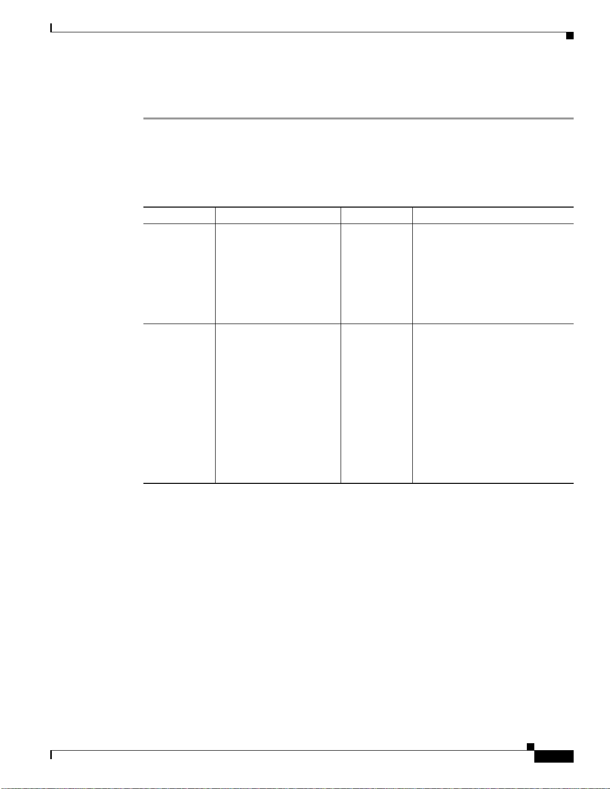
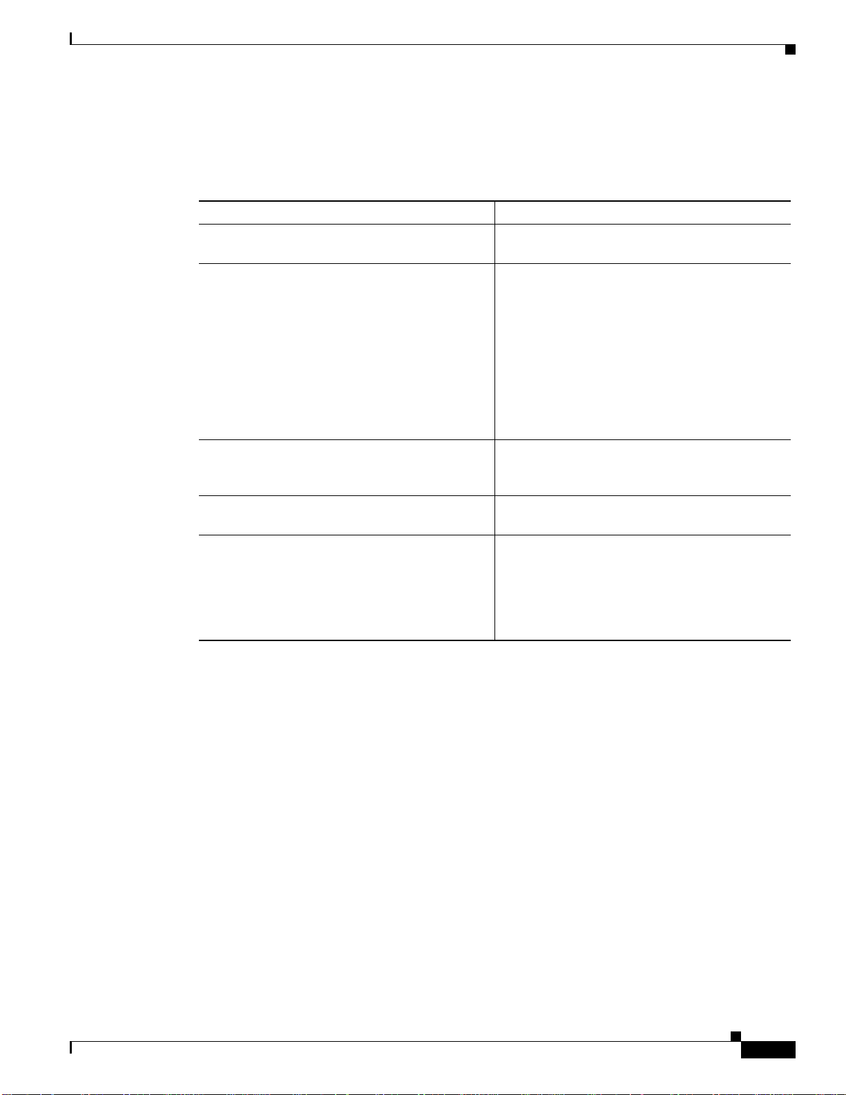
Table 2-1 describes additional settings that can be customized for the Cisco NetFlow Collector
web-based UI.
Table 2-1 Cisco NetFlow Collector User Interface Settings
Setting Description Default Value File
intfc- password Digest password for the
CNS/XML interface. Stored
as a parameter to the
InitServlet in the servlet
configuration file. This
setting must match the md5password value of the
CNS/XML interface.
sessiontimeout
A session is started after a
userlogsin to the web-based
UI. This timeout indicates
the duration of inactivity
allowed before a session
expires and the user is
automatically logged out.
Add:<session-
config><sessiontimeout>30</sessiontimeout></sessionconfig> after all
<servlet-mappings>.
Using the Cisco NetFlow Collector User Interface
password NFC_DIR/tomcat/webapps/nfc/
WEB- INF/web.xml
30 minutes NFC_DIR/tomcat/webapps/nfc/
WEB-INF/web.xml
Using the Cisco NetFlow Collector User Interface
The following sections describe using the Cisco NetFlow Collector User Interface.
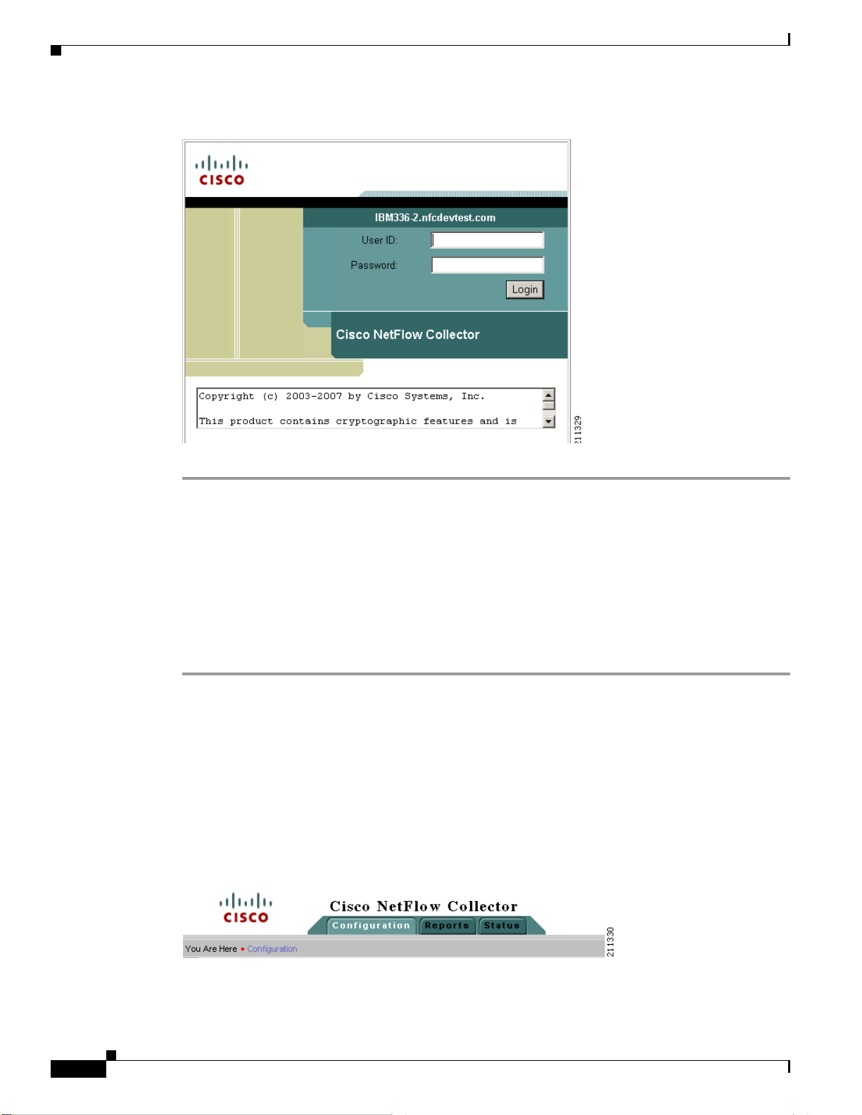
The NFC Login Window
When starting the Cisco NetFlow Collector, the first window that appears is the NFC login window, as
shownin Figure 2-1. For security purposes, to use the web-based UI you must authenticate yourself with
a user ID and password. These values are configured as described in Table 2-1.
Cisco NetFlow Collector User Guide
OL-11399-01
2-3
Page 4
Using the Cisco NetFlow Collector User Interface
Figure 2-1 Cisco NetFlow Collector User Interface Login Window
Chapter 2 Using the NetFlow Collector User Interface
Step 1 From the Login window, enter your User ID and Password.
Step 2 Click Login.
Navigation
To log in to Cisco NetFlow Collector, do the following:
The Cisco NetFlow Collector Main window appears. From this window, you can select from the
following tabs:
• Configuration
• Reports
• Status
See the following sections for information on these functions.
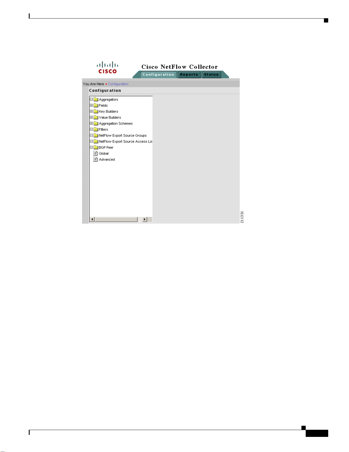
You can move around the NFC web-based user interface (UI) from two levels.Across the top of all NFC
windows are the NFC UI navigation tabs. These tabs are the first level of navigation in to the NFC UI,
as shown in Figure 2-2. From here you can select the Configuration, Reports, and Status tabs. The
toolbar at the far right includes links to Logout, Help, and About windows.
2-4
Figure 2-2 NFC UI Navigation Tabs
Each section of NFC User Interface has a navigation tree on the left-hand side, as shown in Figure 2-3.
This second level of navigation lets you focus in on a specific aspect of collector configuration,
reporting, or status.
Cisco NetFlow Collector User Guide
OL-11399-01
Page 5
Chapter 2 Using the NetFlow Collector User Interface
Figure 2-3 NFC UI Navigation Tree
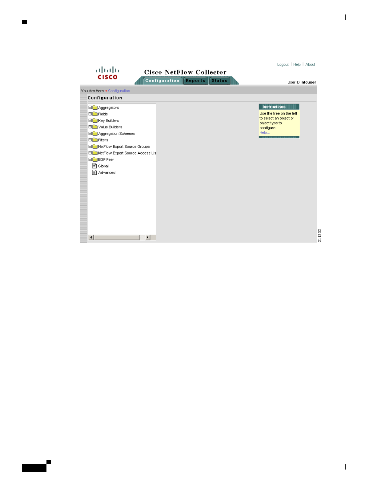
Configuration
Configuration
From the Configuration window you can perform tasks including specify global parameters; define
fields, key builders, value builders and aggregators; and create filters.
From the Cisco NetFlow Collector Main window, click the Configuration tab. The Configuration
window appears, as shown in Figure 2-4.
OL-11399-01
Cisco NetFlow Collector User Guide
2-5
Page 6
Configuration
Chapter 2 Using the NetFlow Collector User Interface
Figure 2-4 NFC Configuration Window
From this window you can access or configure the following:
• Aggregators, page 2-7
• Fields, page 2-10
• Key Builders, page 2-11
• Value Builders, page 2-21
• Aggregation Schemes, page 2-25
• Filters, page 2-26
• NetFlow Export Source Groups, page 2-27
• NetFlow Export Source Access List, page 2-28
• BGP Peer, page 2-29
• Global, page 2-30
• Advanced, page 2-30
2-6
Cisco NetFlow Collector User Guide
OL-11399-01
Page 7
Chapter 2 Using the NetFlow Collector User Interface
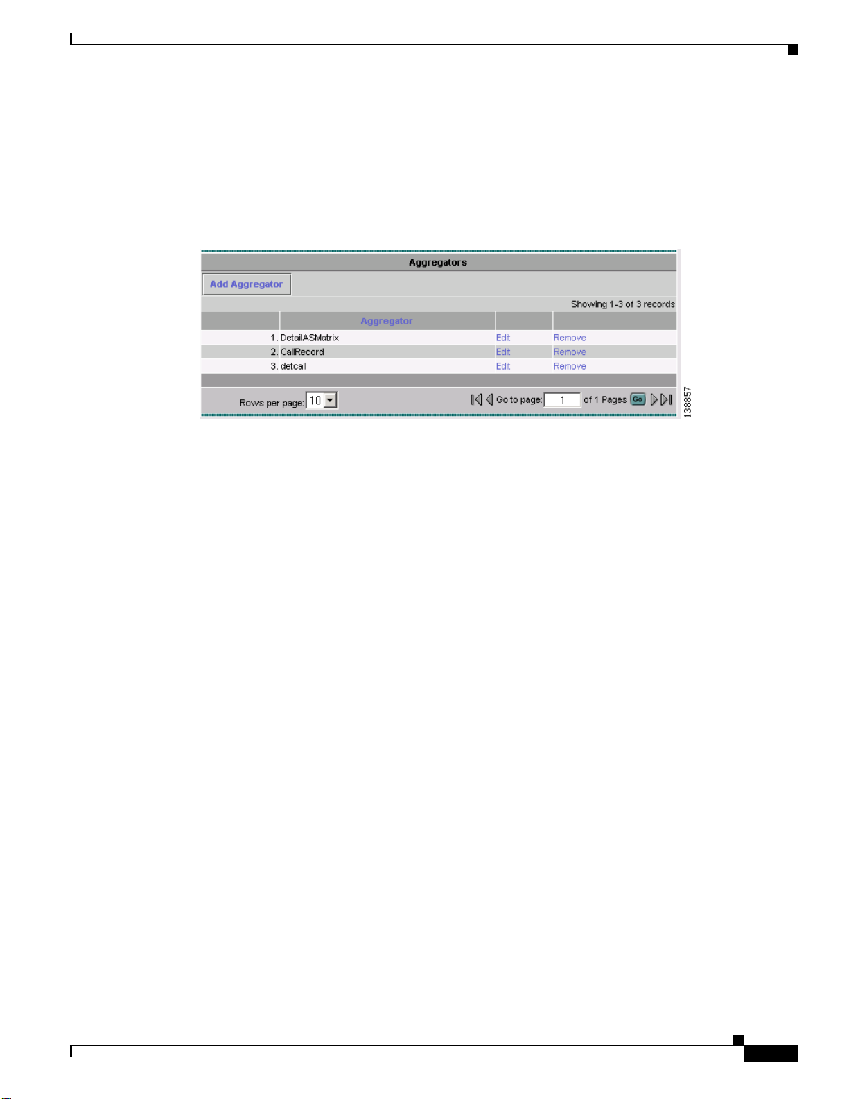
Aggregators
Aggregators define how the Cisco NetFlow Collector receives NetFlow data, aggregates or combines the
data, and generates output files. Click on the Aggregators folder of the NFC UI navigation tree to
display a table of all existing aggregators, as shown in Figure 2-5.
Figure 2-5 Aggregators Window
Configuration
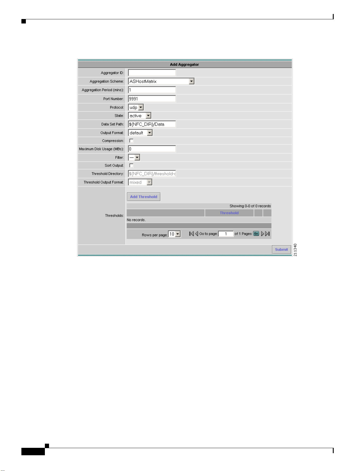
Adding Aggregators
From the Aggregators window, click on Add Aggregator to bring up the Add Aggregator window to
define a new aggregator. See Figure 2-6.
OL-11399-01
Cisco NetFlow Collector User Guide
2-7
Page 8
Configuration
Chapter 2 Using the NetFlow Collector User Interface
Figure 2-6 Add Aggregator Window
Fill in the fields and click Submit to complete the operation.
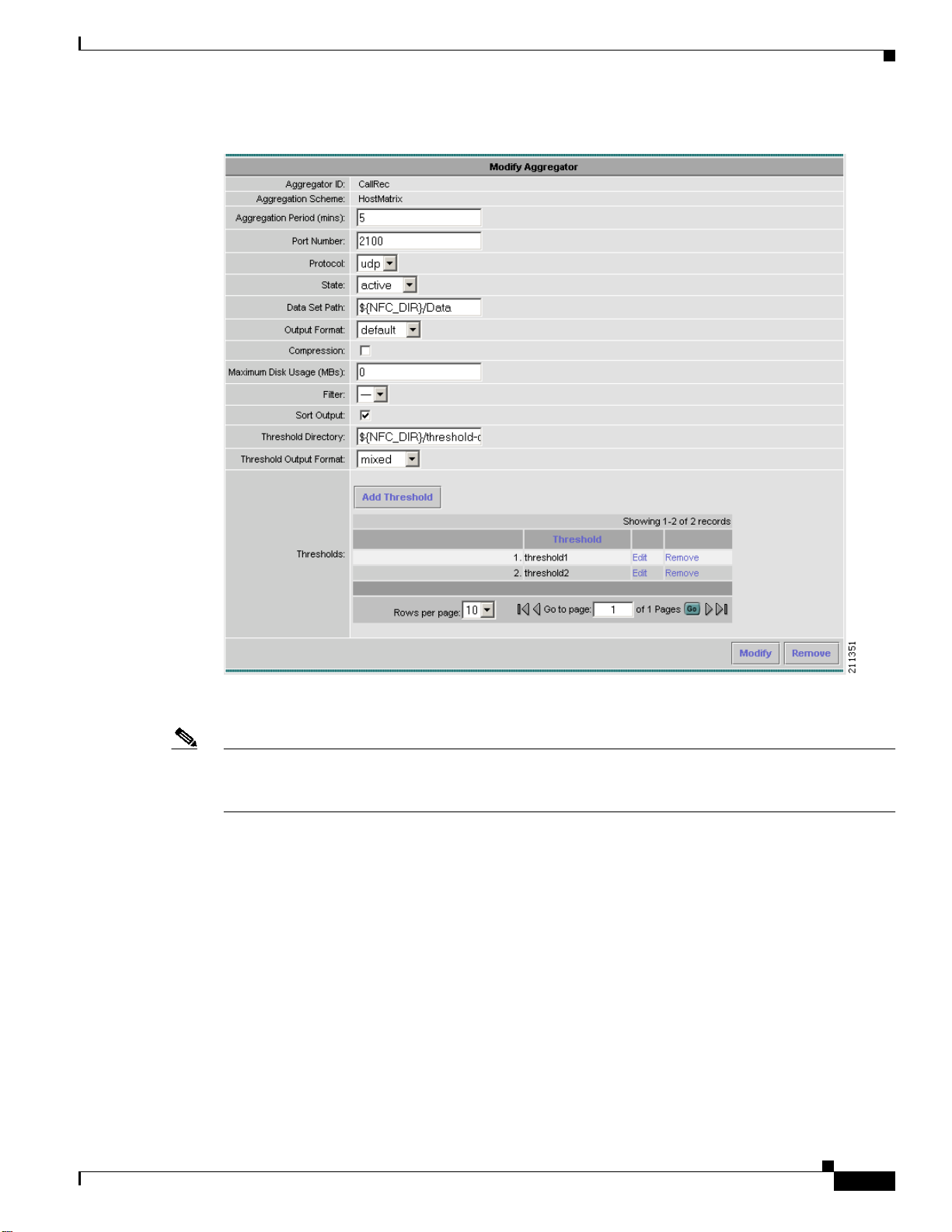
Editing an Aggregator
To modify or remove an existing aggregator, click Edit for the aggregator which you wish to modify or
remove from the list of aggregators displayed in the Aggregator window (Figure 2-6). The Modify
Aggregator window displays, as shown in Figure 2-7.
2-8
Cisco NetFlow Collector User Guide
OL-11399-01
Page 9
Chapter 2 Using the NetFlow Collector User Interface
Figure 2-7 Modify Aggregator Window
Configuration
Thresholds
To modify the selected aggregator, fill in the fields and click Modify to complete the operation. To
remove the selected aggregator, click Remove.
Note When a key or value builder, filter, or aggregation scheme is modified through the web-based user
interface, collector configuration is updated immediately. However, for the update to have an affect on
aggregation and output, the aggregator must be modified or the collector must be restarted.
Thresholds provide a way to generate events when values in the NetFlow Collector output cross a
specified target value. You configure thresholds for each aggregator. A list of thresholds for an
aggregator is displayed in the Add Aggregator window.
From the Add Aggregator window, click Add Threshold to add a new threshold. Click on the
appropriate link in the threshold list to modify or remove an existing Threshold.
When adding and editing thresholds the windows are identical with the exceptionthat you cannot change
the threshold ID when modifying a threshold. Use this window to add, remove, and order threshold
conditions.
The threshold editor is applet-based. A tree on the left-hand side of the threshold editor shows the
elements of the threshold. A form on the right-hand side of the threshold editor contains the attributes
for the currently selected item in the tree.
OL-11399-01
Cisco NetFlow Collector User Guide
2-9
Page 10

Configuration
Chapter 2 Using the NetFlow Collector User Interface
The top item in the tree is the name of the threshold. Directly beneath this is a top-level threshold
condition or expression. Add the top-level threshold condition or expression by selecting Add condition
or Add expression when the top item is selected. If the top-level threshold condition or expression
evaluates to true when the threshold is evaluated, a threshold-crossing log is created. See the “Creating
a Threshold” section on page 4-26 for more information about thresholds.
A threshold expression contains two or more expressions or conditions. Arbitrarily complex threshold
evaluation logic can be specified in this way.
When creating a threshold condition, specify:
• Whether the comparison is greater than, less than, equals, or not-equals
• Which key or value is compared
Directly beneath the threshold condition is one or more value or range items. These determine the set of
target values to which the comparison is applied. Add a value or range to the threshold condition by
selecting Value or Range. For an integer condition, only integer values and ranges can be entered; only
IP address values can be entered for address conditions.
Boolean logic is applied to two or more conditions using an expression. An expression can also appear
within an expression in place of a condition.
To create an expression, specify the logical operator and, or, not-and, or not-or and select Add
expression. An expression must contain at least two other conditions or expressions.
The conditions and expressions within an expression are evaluated in top-down order. Evaluation
performance for an expression can be optimized by placing conditions and expressions which are more
likely to occur closer to the top. Select an item then select Move to move the item up until it reaches the
top; selecting Move again cycles the item to the bottom.
Any item in the tree including the items beneath it can be removed by selecting Remove. Pressing the
back button on the browser also causes any changes to be discarded.
Fields
Note Remove items with care because no cut, paste, or undo capability is provided. Changes are not
committed until you select Update Threshold or Remove Threshold.
The symbol ! at the beginning of any item in the tree indicates that the configuration specified at that
level of the tree is incomplete and must be updated before the threshold can be added or updated.
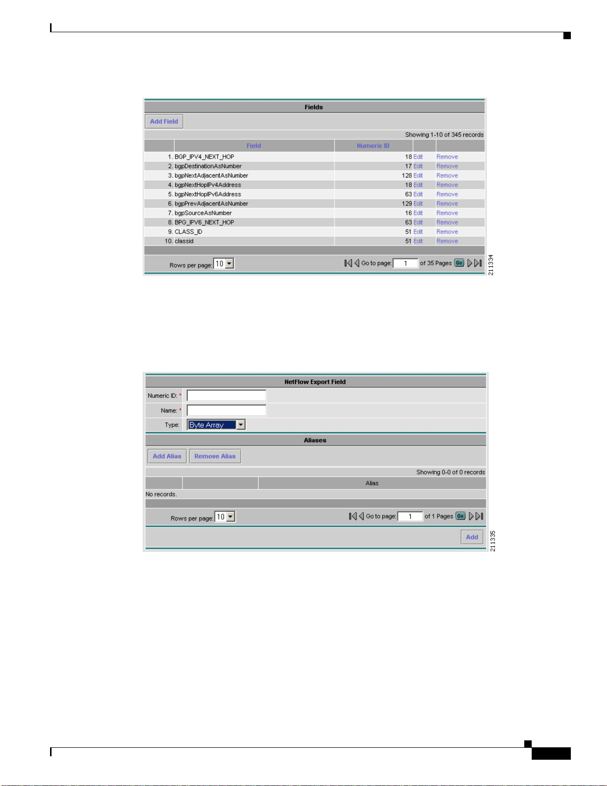
Fields represent individual items of data exported by a device in a NetFlow flow, and are the building
blocks upon which the keys and values referenced by aggregation schemes are based.
Clicking on the Fields folder of the NFC UI navigation tree displays a table of currently defined fields
as shown in Figure 2-8. Click Edit to modify a specificfield,orRemoveto remove a selected field. Click
Add Field to bring up an empty form for defining a new field.
Aliases, alternate names for fields,are also shownin the navigation tree and table and can be added when
a field is defined or modified
2-10
Cisco NetFlow Collector User Guide
OL-11399-01
Page 11
Chapter 2 Using the NetFlow Collector User Interface
Figure 2-8 Fields Window
The NetFlow Export Field window, Figure 2-9, is displayed when adding or modifying a field.Fill in the
form and click Add or Modify to complete the operation. From the Modify window you can also remove
the currently displayed field. Click Add Alias or Remove Alias to add or remove an alias (alternate
name) for this field. See the “Fields” section on page 4-4 for additional information about field
definitions.
Configuration
Key Builders
Figure 2-9 NetFlow Export Field Window
An aggregation scheme consists of keys and values. Within an aggregation period, each value within
flows having the same set of keys is aggregated (typically summed) together with the corresponding
values from earlier matching flows within an aggregation period.
Fields are not referenced directly by an aggregation scheme; instead, a key builder or value builder
references a field, and one or more aggregation schemes references the builder.
Clicking on the Key Builders folder of the NFC UI navigation tree displays a table of currently defined
key builders as shown in Figure 2-10. Click Edit to modify a specific key builder,or Remove to remove
a selected key builder.Click Add Key Builder to bring up an empty form for defininga new key builder.
OL-11399-01
Cisco NetFlow Collector User Guide
2-11
Page 12

Configuration
Chapter 2 Using the NetFlow Collector User Interface
Figure 2-10 Key Builders Window
All key builders have a unique ID and a type. The ID is displayed in the navigation tree and the key
builder table. The attributes shown in the form depend on the type that is selected; different key builder
types have different attributes. The following sections describe the attributes for each type of key
builder:
• BGP Attribute, page 2-13
• Bit Field, page 2-14
• Boolean, page 2-14
• Byte Array, page 2-14
• Customer Name, page 2-15
• Egress PE, page 2-15
• Ingress CE, page 2-16
• Integer, page 2-16
• Integer Range Map, page 2-17
• Interface SNMP Name, page 2-17
• IP Address, page 2-17
• IP Address Range Map, page 2-18
• Mac Address, page 2-18
• Masked IP Address, page 2-18
• Multi-Field Map, page 2-19
• Option Data, page 2-20
• Site Name, page 2-20
• String, page 2-21
• Subnet Address, page 2-21
2-12
Cisco NetFlow Collector User Guide
OL-11399-01
Page 13
Chapter 2 Using the NetFlow Collector User Interface
BGP Attribute
A BGP Attribute key builder looks up a BGP attribute from the Cisco NetFlow Collector BGP peer
using an address from a flow. The complete AS path is a special case that uses both a source and a
destination address from a flow. The BGP Attribute key builder has the following attributes.
Attribute Description
Output name Column name in output; defaults to the field ID if
Attribute type One of the following radio buttons:
Source address key ID of a key builder that returns the source address
Destination address key ID of a key builder that returns the destination
Post-aggregation Determines whether look ups are performed for
Configuration
not specified.
• Complete AS Path
• Well Known Name—Select from ORIGIN,
AS_PATH, NEXT_HOP,
MULTI_EXIT_DESC, LOCAL_PREF,
ATOMIC_AGGREGATOR,
AGGREGATOR, COMMUNITY,
ORIGINATOR_ID, or CLUSTER_LIST
• Integer Type ID.
for a complete AS path look up, otherwise
disabled.
address for querying the attribute.
each flow or at the end of the aggregation period;
this should always be selected, otherwise
attributes are queried from the Cisco NetFlow
Collector BGP peer as flows arrive resulting in a
significant performance impact.
OL-11399-01
Cisco NetFlow Collector User Guide
2-13
Page 14
Configuration
Bit Field
Boolean
Chapter 2 Using the NetFlow Collector User Interface
The Bit Field key builder obtains a subset of bits from a field in a flow. It has the following attributes.
Attribute Description
Output name Column name in output; defaults to the field ID if
not specified.
Field ID of the field in a flow from which to extract bits.
Least significant bit Least significant bit of interest (starts at 0).
Number of bits Number of bits of interest.
Format Decimal or hexadecimal.
Allow null value If not selected, an error is logged if a flowdoes not
contain the indicated field.
A Boolean key builder maps flow values to true, false,orundefined. The Boolean key builder has the
following attributes.
Byte Array
Attribute Description
Output name Column name in output; defaults to the field ID if
not specified.
Field ID of the field in a flow containing the value of
interest.
Allow null value If not selected, an error is logged if a flowdoes not
contain the indicated field.
A Byte Array key builder outputs bytes from flow data in hexadecimal format. The Byte Array key
builder has the following attributes.
Attribute Description
Output name Column name in output.
Field ID of the field to obtain from a flow.
Offset Starting byte offset from the beginning of the field
in the flow. Set to zero if not specified.
Length Number of bytes of interest, from the offset to the
end of field data if not specified.
Allow null value If not selected, an error is logged if a flowdoes not
contain the indicated field.
2-14
Cisco NetFlow Collector User Guide
OL-11399-01
Page 15
Chapter 2 Using the NetFlow Collector User Interface
Customer Name
The Customer Name key builder resolves the customer name from the input interface field. It has the
following attributes:
Attribute Description
Output name Column name in output.
Field ID of the field to obtain from a flow.
Allow null value If not selected, an error is logged if a flowdoes not
The Customer Name key builder requires configuration in the config/vpn.conf file. You must include
one row to correspond to each PE device VPN interface that export NetFlow packets to this NFC server.
The rows in this file contains five fields, in the following order: exporting device (PE) IP address,
interface name, name of the site to which this interface is connected, CE to which this interface is
connected, and customer name. These fieldsshould be separated by commas. See the following example:
172.20.98.250,FastEthernet0/1.401,vpn1-branchB,CERouter-3,Cisco
172.20.98.250,FastEthernet0/1.601,vpn2-branchB,CERouter-4,IBM
172.20.98.248,FastEthernet2/1,vpn2-branchA,CERouter-2,IBM
172.20.98.246,FastEthernet0/1,vpn1-branchA,CERouter-1,Cisco
Configuration
contain the indicated field.
Egress PE
The exporting device (PE) IP address and interface name fields are required. You can include empty
strings for the remaining fields in each row if those fieldsdo not need to be resolved. For example, if you
do not need to specify a site name, the site name fields can be left empty.
Note Each row must contain four commas. Empty fields must be separated with commas.
The Egress PE key builder resolves the egress PE from the BGP nexthop field. It has the following
attributes:
Attribute Description
Output name Column name in output.
Field ID of the field to obtain from a flow.
Allow null value If not selected, an error is logged if a flowdoes not
contain the indicated field.
This key builder requires configuration in the config/peList.conf file. This file should include the
loopback addresses or hostnames of all PEs in the network. See the following sample:
# This file is for the PE-PE traffic summary only # It should contain a list of IDs
for all PE devices in the provider network # ID of PE device can be either host name
or IP address
192.168.200.2
192.168.200.3
192.168.200.4
OL-11399-01
Cisco NetFlow Collector User Guide
2-15
Page 16

Configuration
Ingress CE
Chapter 2 Using the NetFlow Collector User Interface
The Ingress CE key builder resolves the ingress CE from the input interface field. It has the following
attributes:
Attribute Description
Output name Column name in output.
Field ID of the field to obtain from a flow.
Allow null value If not selected, an error is logged if a flowdoes not
contain the indicated field.
This key builder requires configuration in the config/peList.conf file. You must include one row to
correspond to each PE device VPN interface that export NetFlow packets to this NFC server. The rows
in this file contains five fields, in the following order: exporting device (PE) IP address, interface name,
name of the site to which this interface is connected, CE to which this interface is connected, and
customer name. These fields should be separated by commas. See the following example:
172.20.98.250,FastEthernet0/1.401,vpn1-branchB,CERouter-3,Cisco
172.20.98.250,FastEthernet0/1.601,vpn2-branchB,CERouter-4,IBM
172.20.98.248,FastEthernet2/1,vpn2-branchA,CERouter-2,IBM
172.20.98.246,FastEthernet0/1,vpn1-branchA,CERouter-1,Cisco
Integer
An Integer key builder obtains an integer value from a flow. It has the following attributes.
Attribute Description
Output name Column name in output; defaults to the field ID if
not specified.
Field ID of the field in a flow.
Format Decimal or hexadecimal.
Allow null value If not selected, an error is logged if a flowdoes not
contain the indicated field.
2-16
Cisco NetFlow Collector User Guide
OL-11399-01
Page 17

Chapter 2 Using the NetFlow Collector User Interface
Integer Range Map
An Integer Range Map key builder obtains an integer from a flow and maps the value to a string. It has
the following attributes.
Attribute Description
Output name Column name in output; defaults to the field ID if
Field ID of the field in a flow.
Allow null value If not selected, an error is logged if a flowdoes not
Default label Mapping result if no match is found.
Mapping information appears in the Integer Ranges list. Each list item contains an integer value or range
and the label it maps to. Labels can appear more than once, but duplicate or overlapping values and
ranges are not allowed. Click on Add Range to add a new value or range.
Configuration
not specified.
contain the indicated field.
Interface SNMP Name
The Interface SNMP Name key builder maps an interface index to an interface name obtained via
SNMP. It has the following attributes.
Attribute Description
Output name Column name in output.
Field ID of the fieldto obtain from a flowcontaining the
Allow null value If not selected, an error is logged if a flowdoes not
IP Address
An IP Address key builder obtains an IP address from a flow. It has the following attributes.
Attribute Description
Output name Column name in output; defaults to the field ID if
Field ID of the field in a flow.
Format Standardnotation, hostname (via a DNS look up),
Allow null value If not selected, an error is logged if a flowdoes not
interface index.
contain the indicated field.
not specified.
or integer. Note: The integer format is obsolete
and should not be used. It is retained for
backwards compatibility.
contain the indicated field.
OL-11399-01
Cisco NetFlow Collector User Guide
2-17
Page 18

Configuration
IP Address Range Map
An IP Address Range Map keybuilder obtains an IP address from a flowand maps the value to a string.
It has the following attributes.
Attribute Description
Output name Column name in output; defaults to the field ID if
Field ID of the field to look up from flows.
Allow null value If set to false (default) and a flow does not contain
Default label Output value if no mapping result is found;
Mapping information appears in the IP Address Ranges list. Each list item contains an IP address value
or range and the label it maps to. Labels can appear more than once, but duplicate or overlapping values
and ranges are not allowed. Click Add range to add a new value or range.
Chapter 2 Using the NetFlow Collector User Interface
not specified.
field, an error is logged. I f set to true, the output
value is empty and no error is logged.
otherwise if not specified the value itself is output.
Mac Address
The Mac Address key builder reads and outputs an MAC address. It has the following attributes.
Attribute Description
Output name Column name in output; defaults to the field ID if
Field ID of the field to look up from flows.
Allow null value If set to false (default) and a flow does not contain
Masked IP Address
The Masked IP Address key builder is obsolete and should not be used. It will be removed in a
subsequent release.
not specified.
field, an error is logged. If set to true, the output
value is empty and no error is logged.
2-18
Cisco NetFlow Collector User Guide
OL-11399-01
Page 19

Chapter 2 Using the NetFlow Collector User Interface
Multi-Field Map
The Multi-Field Map editor is applet-based and is different than the forms for other key builder types
because of the hierarchical nature of a multi-field map. A tree on the left-hand side of the Multi-Field
Map editor shows the elements of the map. A form on the right-hand side of the Multi-Field Map editor
shows the attributes for the selected item in the tree.
The top level of the tree contains the following attributes.
Attribute Description
ID ID that uniquely identifies this map.
Output name Column name displayed in output for this key
Default label Default value shown in output if no match for the
Beneath the top level of the tree are one or more conditions. After selecting the top tree item, create a
condition as follows:
1. Select the condition type (integer, IP address, or string).
2. Choose the key builder that will produce values for the condition.
3. Click Add condition.
A new condition will be added following all other conditions at that level and will be selected in the tree.
The form displayed on the right side will display the new condition. In this form, select Add case one
or more times to add cases for each value or range of interest. A new tree item for the case is added
following all other cases under this condition's tree item; the new tree item is selected; and a form for
the case is displayed on the right hand side.
A single case has one or more values and ranges and the label associated with a match for these values
and ranges. The values and ranges for one case must be unique for all cases for this condition. To add a
value or range to the case, select Add value or Add range. A new value or range is added to the case; a
tree item for the value or range is added beneath the case's tree item; and a form is displayed on the right
hand side for the new value or range.
Each case can also have one or more conditions nested beneath it that reference a different key builder.
Therefore for a particular value, range, or set of values for one key, the value of a different key can
further refine the result of the multi-field map. Conditions are added to a case as described above for
adding conditions to the top level of the tree.
Selecting Move for a case or condition moves the tree item for the case or condition up. After the item
is at the top, it cycles back to the bottom. The order of cases has no impact on performance when
evaluating a condition. However, because the conditions at one level in the tree are evaluated top-down
in the order they appear, the order of conditions within one level can have an effect on performance.
Therefore, if one condition is more likely than another, declare it first or move it before less likely
conditions.
Any item in the tree including the items beneath it can be removed by selecting Remove. Pressing the
back button on the browser also causes any changes to be discarded. Remove items with care because
no cut, paste, or undo capability is provided. Changes are not committed until you select Update map
or Remove map.
The symbol [ !]at the beginning of any item in the tree indicates that the configuration specified at that
level of the tree is incomplete and must be updated before the multi-field map can be added or updated.
Configuration
builder.
specified conditions is found.
OL-11399-01
Cisco NetFlow Collector User Guide
2-19
Page 20

Configuration
Option Data
Site Name
Chapter 2 Using the NetFlow Collector User Interface
An Option Data key builder obtains one or more key values from a flow and performs a look up using
this result from an option data cache. The result of the mapping is the corresponding value from option
data that was specified in the option data cache entry definition. The Option Data key builder has the
following attributes.
Attribute Description
Output name Column name in output.
Option data map entry ID of an option-data-map-entry element declared
in option-data-map in XML configuration.
Keys ID of one or more key builders to produce values
corresponding with the keys in the specified
option-data-map-entry.
The Site Name key builder resolves the customer site name from the input interface field. It has the
following attributes:
Attribute Description
Output name Column name in output.
Field ID of the field to obtain from a flow.
Allow null value If not selected, an error is logged if a flowdoes not
contain the indicated field
This key builder requires configuration in the config/vpn.conf file. You must include one row to
correspond to each PE device VPN interface that export NetFlow packets to this NFC server. The rows
in this file contains five fields, in the following order: exporting device (PE) IP address, interface name,
name of the site to which this interface is connected, CE to which this interface is connected, and
customer name. These fields should be separated by commas. See the following example:
172.20.98.250,FastEthernet0/1.401,vpn1-branchB,CERouter-3,Cisco
172.20.98.250,FastEthernet0/1.601,vpn2-branchB,CERouter-4,IBM
172.20.98.248,FastEthernet2/1,vpn2-branchA,CERouter-2,IBM
172.20.98.246,FastEthernet0/1,vpn1-branchA,CERouter-1,Cisco
2-20
Cisco NetFlow Collector User Guide
OL-11399-01
Page 21

Chapter 2 Using the NetFlow Collector User Interface
String
A String key builder obtains a UTF-8 string value from a flow. It has the following attributes.
Attribute Description
Output name Column name in output.
Field ID of the field to obtain from a flow.
Regrex filter If specified, the regular expression is applied to
Allow null value If not selected, an error is logged if a flowdoes not
Subnet Address
A Subnet Address key builder obtains an IP address and mask from a flow, applies the mask to the
address, and outputs a network address in the format n.n.n.n/m. It has the following attributes.
Configuration
the string in flow data. The first matching
sequence becomes the value of the key. If the
regrex contains one or more capturing groups, the
first match is returned.
contain the indicated field
Value Builders
Attribute Description
Output name Column name in output.
Address field ID of the address field to obtain from a flow.
Mask field ID of the mask field to obtain from a flow.
Allow null value If not selected, an error is logged if a flowdoes not
contain the indicated field
A value builder is associated with one or more fields in flow data and produces a non-key value in an
aggregation record. A value builder can be referenced by an Aggregation Scheme and corresponds with
one column in a NetFlow Collector output file.
Clicking on the Value Builders folder of the navigation tree displays a table of all existing value
builders, as shown in Figure 2-11. Click on the appropriate link to modify or remove a value builder.
OL-11399-01
Cisco NetFlow Collector User Guide
2-21
Page 22

Configuration
Chapter 2 Using the NetFlow Collector User Interface
Figure 2-11 Value Builders
Click on Add Value Builder to bring up an empty form for defining a new value builder. A value builder
is created by specifying its type, associating it with a field(sometimes two or more fields such as for the
Active Time type as shown in Figure 2-12), and specifying attributes specific to the selected type.
Different forms are displayed depending on which value builder type is selected.
When Add Value Builder or Edit is selected, a form for editing the value builder definitionis displayed.
All value builders have an ID and Type. The ID must be unique for all value builders; the Type
determines the algorithm used to create the value. The remaining attributes that are shown in the Value
Builder form are determined by which type is selected.
Figure 2-12 Adding a Value Builder
See the “Keysand Values”section on page 4-5 for additional information about value builder definitions.
2-22
Cisco NetFlow Collector User Guide
OL-11399-01
Page 23

Chapter 2 Using the NetFlow Collector User Interface
Active Time
The Active Time value builder obtains a start time and an end time from fields in a flow and calculates
the difference. It has the following attributes.
Attribute Description
Name Column name in output.
Start time field ID of the start time field to obtain from a flow.
End time field ID of the end time field to obtain from a flow.
Usage Always leave set as Count.
Directional Sum
The Directional Sum value builder obtains an integer value from a field in a flow and adds it to a count
if the flow direction agrees with what you specify with the Egress attribute. It has the following
attributes.
Attribute Description
Output Name Column name in output.
Field ID of the integer field to obtain from a flow.
Egress Boolean attribute to indicate if flow direction is
Configuration
egress or not.
End Time
Flow Count
The End Time value builder obtains an end time from a field in a flow. It has the following attributes.
Attribute Description
Name Column name in output.
End time field ID of the end time field to obtain from a flow.
The Flow Count value builder increments a count for each flow. It has the following attributes.
Attribute Description
Name Column name in output.
Usage Always leave set as Count.
OL-11399-01
Cisco NetFlow Collector User Guide
2-23
Page 24

Configuration
Max Flow Byte Rate
The Max Flow Byte Rate value builder determines the byte rate for each received flow and outputs the
highest value found for all flows in an aggregation period. This builder was referred to as Max Burst Rate
in previous releases. It has the following attributes.
Attribute Description
Name Column name in output.
Start time field ID of the start time field to obtain from a flow.
End time field ID of the end time field to obtain from a flow.
Byte count field ID of the byte count field to obtain from a flow.
Usage Always leave set as Maximum.
Rate
The Rate value builder determines a rate by dividing the result of another value by the amount of time
in the aggregation period. It has the following attributes.
Chapter 2 Using the NetFlow Collector User Interface
Start Time
Sum
Attribute Description
Name Column name in output.
Quantity value ID of another value builder used to determine the
quantity.
Units Scales the result to seconds or minutes.
The Start Time value builder obtains a start time from a field in a flow. It has the following attributes...
Attribute Description
Name Column name in output.
Start time field ID of the start time field to obtain from a flow.
The Sum value builder obtains an integer value from a field in a flow and adds it to a count. It has the
following attributes.
Attribute Description
Name Column name in output.
Field ID of the integer field to obtain from a flow.
Allow null value If not selected and the flow does not contain the
specified field, an error is logged.
2-24
Cisco NetFlow Collector User Guide
OL-11399-01
Page 25

Chapter 2 Using the NetFlow Collector User Interface
Sum with Sampling Estimation
The Sum with Sampling Estimation value builder obtains an integer value from a field in a flow,
multiplies by the sampling rate in effect, and adds the estimate to a count. If not used with V9 export,
the value is not scaled because the sampling rate is not known. It has the following attributes.
Attribute Description
Name Column name in output.
Field ID of the integer field to obtain from a flow.
Sampling Interval Builder ID Always use the default value.
Allow null value If not selected and the flow does not contain the
Aggregation Schemes
Aggregation schemes define the set of keys and values used for aggregation and that appear in the Cisco
NetFlow Collector output files. Clicking on the Aggregation Schemes folder of the navigation tree
displays a table of all existing aggregation schemes, as shown in Figure 2-13. Click on the appropriate
link to modify or remove an aggregation scheme. Click on Add Aggregation Scheme to bring up an
empty form for defining a new aggregation scheme.
Configuration
specified field, an error is logged.
Figure 2-13 Aggregation Schemes
The Add AggregationScheme and Modify AggregationScheme in windows, as shownin Figure 2-14,
are identical with the exception that you cannot change the Aggregation Scheme ID on the Modify
Aggregation Scheme window. Use this form to select key and value fields and click Add or Modify
respectively to complete the operation. From the Modify Aggregation Scheme window you can also
remove the currently displayed aggregation scheme.
OL-11399-01
Cisco NetFlow Collector User Guide
2-25
Page 26

Configuration
Chapter 2 Using the NetFlow Collector User Interface
Figure 2-14 Modify Aggregation Scheme
Filters
Note Removing an aggregation scheme that is in use by an aggregator can succeed but cause an invalid
reference after the collector is restarted.
Filters provide a way to limit the amount and content of data that an aggregator processes. Clicking on
the Filters folder of the navigation tree displays a table of all existing filters, as shown in Figure 2-15.
Click on the appropriate link to modify or remove a filter. Click on Add Filter to bring up an empty form
for defining a new filter.
Figure 2-15 Filters
When adding and editing filters the windows are identical with the exception that you cannot change the
Filter ID when modifying a filter. Use this form to add, remove, and order filter conditions.
2-26
Cisco NetFlow Collector User Guide
OL-11399-01
Page 27

Chapter 2 Using the NetFlow Collector User Interface
The Filter editor is applet-based. A tree on the left hand side of the filter editor shows the elements of
the filter. A form on the right hand side of the filter editor contains the attributes for the currently selected
item in the tree.
The top item of the tree contains a unique identifier for the filter. Directly beneath the top of the tree is
one filter condition or filter expression. Add the top-level filter condition or expression by selecting Add
condition or Add expression when the top item is selected.
A filter condition performs an equality check on the output value of a key builder that is invokedfor each
flow. The type of a filter condition is either an integer condition, address condition, string condition, or
nde-source condition. Depending on which condition type you select, only the key builders that produce
that type of valuecan be selected. The nde-source condition checks the address of the device from which
the flow originated.
When creating a filter condition, specify:
• Whether the equality check is equals or not-equals
• Which key builder creates the value to be checked
In addition, an address condition accepts an optional integer mask value that is applied to the address
before the equality check is performed. If the mask field is left blank, no mask is applied.
Directly beneath the filtercondition is one or more valueor range items. These determine the set of target
values to which the equality check is applied. Add a value or range to the filter condition by selecting
Add value or Add range. For an integer condition, only integer values and ranges can be entered; only
IP address values can be entered for address filter conditions. An nde-source condition accepts only IP
address values. Note that ranges cannot be entered for string filter conditions, only single values.
Boolean logic is applied to two or more filterconditions using a filter expression. A filter expression can
also appear within an expression in place of a filter condition.
To create a filter expression, specify the logical operator and, or, nand (not-and), or nor (not-or) and
select Add expression. An expression must contain at least two other conditions or expressions.
The conditions and expressions within an expression are evaluated in top-down order. Evaluation
performance for an expression can be optimized by placing conditions and expressions which are more
likely to occur to the top. Select an item then select Move to move the item up until it reaches the top;
selecting Move again cycles the item to the bottom.
Any item in the tree including the items beneath it can be removed by selecting Remove. Pressing the
back button on the browser also causes any changes to be discarded.
Configuration
Note Remove items with care since no cut, paste, or undo capability is provided. Changes are not committed
until you select Update filter or Remove filter.
The symbol [ !]at the beginning of any item in the tree indicates that the configuration specified at that
level of the tree is incomplete and must be updated before the filter can be added or updated.
NetFlow Export Source Groups
By default, flows are aggregated with other flows from the source address of the originating device.
However, if multiple source addresses appear in one export Source Group, flows from these multiple
sources are aggregated together.
Note The collector must be restarted for configuration changes to an existing source group to take effect.
OL-11399-01
Cisco NetFlow Collector User Guide
2-27
Page 28

Configuration
Chapter 2 Using the NetFlow Collector User Interface
Click on the NetFlow Export Source Groups folder of the navigation tree to display a table of currently
defined source groups, as shown in Figure 2-16. Click on the appropriate link to modify or remove a
group. Click Add Group to bring up an empty form for defining a new source group.
Figure 2-16 NetFlow Export Source Groups
The NDE Source Group window,as shown in Figure 2-17,is shown when adding or modifying a source
group. Fill in the form and click Add or Modify to complete the operation. Select Add Source to add
an IP address to the group. From the Modify windowyou can also remove the currently displayed source
group. See the “Creating Source Groups” section on page 4-24 for additional information about source
groups.
Figure 2-17 NDE Source Group
NetFlow Export Source Access List
By default, Cisco NetFlow Collector collects from any device that sends NetFlow data to it. However,
by specifying a NetFlow Export Source Access List, you can configure Cisco NetFlowCollector to reject
data from certain devices or to accept data only from certain devices.
Note The collector must be restarted for configuration changes to the source access list to take effect.
2-28
Click on the NetFlow Export Source Access List folder of the navigation tree to display the current
access list, as shown in Figure 2-18. If Action is Permit, NetFlow data is permitted only from the
selected devices and groups; if Action is Deny, NetFlow data is rejected from the selected devices and
groups.
Cisco NetFlow Collector User Guide
OL-11399-01
Page 29

Chapter 2 Using the NetFlow Collector User Interface
Click on the appropriate link to add or remove a source device or group. Note that groups are obtained
from the NetFlow Export Source Groups page. See the “Creating Access Lists” section on page 4-24 for
additional information about configuring source access lists.
Figure 2-18 NDE Source Access List
Configuration
BGP Peer
OL-11399-01
Click the BGP Peer folder of the NFC UI navigation tree to display the configuration for the Cisco
NetFlowCollector BGP peer, as shownin Figure 2-19.Click on Add Remote Peer to specify a newBGP
peer. If the BGP Identifier field is left blank, the BGP identifier of the Cisco NetFlow Collector BGP
peer defaults to the integer value of this host's IP address.
Note The BGP Peer must be stopped and restarted for configurationupdates to take effect. See the “BGP Peer”
section on page 5-8 for additional information about BGP Peer configuration.
Cisco NetFlow Collector User Guide
2-29
Page 30

Configuration
Chapter 2 Using the NetFlow Collector User Interface
Figure 2-19 Local Peer Settings Window
Global
Advanced
The settings in Figure 2-20 affect how the Cisco NetFlow Collector works in general. They are not
specificto any aggregator, aggregation-scheme, or filter. Make any changes necessary and click Submit
to store them. Some settings do not take affect until the Cisco NetFlow Collector is restarted.
Figure 2-20 Global Parameters Window
2-30
The Advanced window lets you send any XML request to the collector. Clicking on the Advanced node
in the NFC UI navigation tree brings up a form with a template for an XML request. Add the content of
the XML request inside the <nfc> tag. See the “Supported XML Requests” section on page E-3 for a
description of valid XML requests.
Cisco NetFlow Collector User Guide
OL-11399-01
Page 31

Chapter 2 Using the NetFlow Collector User Interface
In limited cases where the configuration is more complex than the web-based UII supports, you will be
directed to the Advanced window and the XML for the selected component will appear in the text area.
Changes can then be made and submitted by clicking Submit XML.
XML responses from the collector are displayed in Figure 2-21 in the text area after submitting a request.
Figure 2-21 Advanced Configuration Window
Reports
Reports
OL-11399-01
Cisco NetFlow Collector reports are in effect a summary of the NetFlow Collector’s aggregated output.
NetFlow data is first aggregated into NetFlow Collector output files by the collector, and then the data
in those files is further aggregated to generate a report. Reports are either custom (run immediately) or
scheduled.
From the Cisco NetFlow Collector Main window, click the Reports tab. The Reports window appears,
as shown in Figure 2-22.
Cisco NetFlow Collector User Guide
2-31
Page 32

Reports
Figure 2-22 Reports Window
From this window you can select the following:
Custom Reports
Chapter 2 Using the NetFlow Collector User Interface
• Custom Reports, page 2-32
• Scheduled Reports, page 2-37
Custom reports are generated on demand from the NetFlow Collector output files on the collector
machine. From the Custom Reports window, as shown in Figure 2-23, you can specify data that you
want in the report and how you want it aggregated.
2-32
Cisco NetFlow Collector User Guide
OL-11399-01
Page 33

Chapter 2 Using the NetFlow Collector User Interface
Figure 2-23 Custom Reports Window
Reports
OL-11399-01
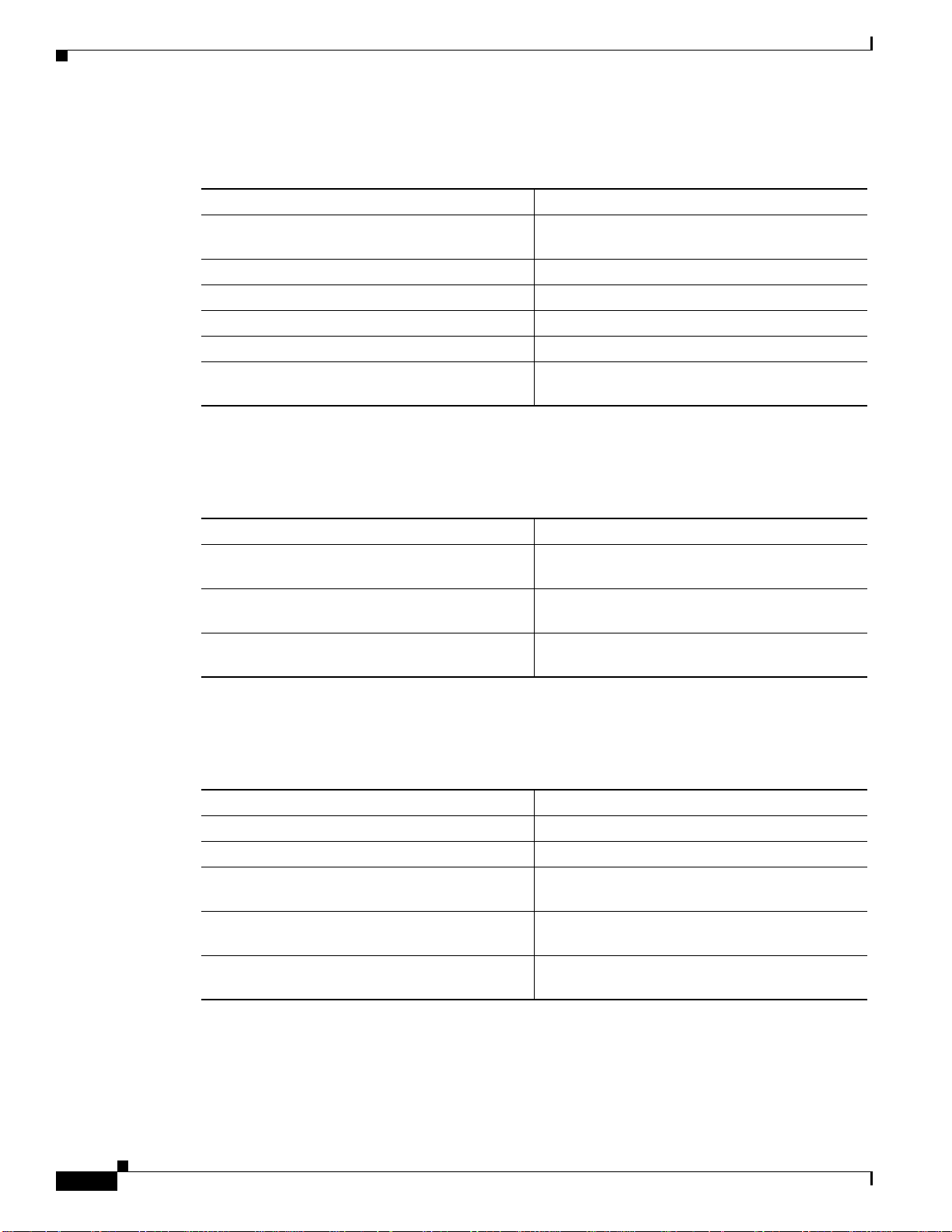
The fields of the Custom Reports form are described in Table 2-2.
Cisco NetFlow Collector User Guide
2-33
Page 34

Reports
Chapter 2 Using the NetFlow Collector User Interface
Table 2-2 Custom Reports Fields
Field Value Description
Start Date A date string in the format of
dd MMM yyyy where dd is the day of the
month, MMM is the abbreviated name of
The data for the report will come from
Cisco NetFlow Collector output files that
were generated on or after this date.
the month, and yyyy is the four digit year.
For example, 01Jan2074 for January 1st,
2007.
Start Time A time string in the format of hh:mm:ss
where hh is the hour of the day in 24 hour
notation, mm is the minute of the hour,
The data for the report will come from
Cisco NetFlow Collector output files that
were generated at or after this time.
and ss is the seconds of the minute. For
example, 13:05:00 for 1:05PM and 0
seconds.
End Date A date string in the format of
dd MMM yyyy where dd is the day of the
month, MMM is the abbreviated name of
The data for the report will come from
Cisco NetFlow Collector output files that
were generated on or before this date.
the month, and yyyy is the four digit year.
For example, 01Jan2007 for January 1st,
2007.
End Time A time string in the format of hh:mm:ss
where hh is the hour of the day in 24 hour
notation, mm is the minute of the hour,
The data for the report will come from
Cisco NetFlow Collector output files that
were generated at or before this time.
and ss is the seconds of the minute. For
example, 13:05:00 for 1:05PM and 0
seconds.
Relative Date
and Time
Either the start and end date and time
specified, or the calculated hour, day,
week, or month relative to the current
time. Also useful when creating report
templates that are recalled and run later at
the same relative time.
Selecting a relative time sets the start and
end time relative to the current time. For
example, if you select Current hour, the
time range starts at the current hour of the
day. If you select Previous hour, the last
entire hour is shown. If you select Until
now, the time range is set to end at the
current time.
2-34
Cisco NetFlow Collector User Guide
OL-11399-01
Page 35

Chapter 2 Using the NetFlow Collector User Interface
Table 2-2 Custom Reports Fields (continued)
Field Value Description
Devices Combine devices, Separate devices, or
Single device. For Single device the
value should be the IP address of the
device.
Aggregator One of the defined aggregators The report data will come from the Cisco
Keys The set of keys that are defined in the
aggregation scheme used by the selected
aggregator, or a subset of these keys.
Values The set of values that are defined in the
aggregation scheme used by the selected
aggregator, or a subset of these values.
Reports
Combinedevicesspecifiesthatthe report
will aggregate data from different
exporting devices into records based
solely on the specified keys (See below).
Each row of the report will contain a * for
the value of the Device column.
Separate devices specifies that the report
will treat the exporting device as an
additional key for aggregation. As a
result,data from different deviceswill not
be aggregated together and the exporting
device that generated the report data will
be the value of the Device column for
each row of the report.
Single device allows you to filter report
data to that which came from a single
exporting device. The IP address of the
exporting device will be the value of the
Device column for each row of the report.
In NFC Release 6.0, a selection box is
provided for specifying a single device.
You can select any device for which data
is available. If the selections set is empty,
no data is available for the selected
aggregator.
NetFlow Collector output files of this
single aggregator.
Report data will be aggregated for each
unique combination of keys selected for
the report. Using a subset of keys reduces
the system memory required to generate
the report.
Value columns of the report are
aggregated for each unique combination
of keys selected for the report. Using a
subset of values reduces the system
memory required to generate the report.
In NFC Release 6.0, three sets of value
selections are provided. The firstistheset
of value columns availablein output data.
For integer values, the second and third
sets allow per-minute and per-second
rates calculated over the reporting period
to be selected.
OL-11399-01
Cisco NetFlow Collector User Guide
2-35
Page 36

Reports
Chapter 2 Using the NetFlow Collector User Interface
Table 2-2 Custom Reports Fields (continued)
Field Value Description
Report Type Top-N or Bottom-N Specifiesif the report shows the Top-Nor
Bottom-N values as determined by the
Ordered By value selection.
N (Maximum
Rows)
A positive integer, N, no greater than
2147483647. Default value is 10.
The maximum number of rows the report
should contain for each exporting device.
The total number of unique records in all
the Cisco NetFlow Collector data files
being reported can be much greater than
the number of the records one might want
to present in a report. Use this field to
limit the number of records contained in
the report.
You can sort all aggregated unique
records in descending (or ascending)
order, according to a user-specifiedvalue
field, and present the first or last N
records in the report. To show the relative
magnitude of data that is not displayed,
all records , not just those returned, can
be optionally aggregated in to one record
with key value of All.
IncludeRecord
All
Yes or No. The default value is No. Specifies whether to include the record
with key value of All. If set to Yes, the All
record will be calculated and appear in
the report.
After filling in the fields in the Custom Report window, you can select one of the following actions:
• Generate—Runs the report in a separate browser window. A progress bar is shown until the report
• Generate XML—Displays the underlying report XML in the browser window, which you can save
• Save as Template—Saves the report form contents as a template.
Report Templates
In NetFlow Collector Release 6.0, Report Templates replace and improve upon the Common Reports
feature in previous releases. You can save the contents of a partially filled out custom report form as a
template by selecting Save as Template and naming the template. You can then recall the template at
any later time to run the report. This is particularly useful when used in conjunction with a relative date
and time specification in the custom report form.
Report Templates are listed in the navigation tree under Custom Reports. When you select Custom
Reports in the navigation tree, the list of Report Templatesis displayed as displayed in Figure 2-24.To
run a report based on the template, select the template name in the navigation tree or select Create
report in the report template list. You can remove a template by selecting Remove in the Report
Template list.
is displayed.
as a file.
2-36
Cisco NetFlow Collector User Guide
OL-11399-01
Page 37

Chapter 2 Using the NetFlow Collector User Interface
Figure 2-24 Report Templates List
If you select Save as Template in a custom report form that was created from a template, you can modify
the template definition if you keep the existing template name when prompted for the name. You can
also create a new template by specifying a new name.
For example, to create an hourly top-talkers report template for the previous hour, do the following:
Step 1 Navigate Reports > Custom Reports.
Step 2 Click the Previous hour radio button to specify the Relative Date and Time.
Step 3 Select the Devices strategy to use. Specify either Combined devices or Single device.
Step 4 Select an aggregator whose aggregation scheme contains the srcaddr key and octets value.
Step 5 Select the srcaddr key and octet value.
Step 6 Click Save as Template.
Step 7 Enter the template name as previous-hour-top-talkers and click OK.
The template is saved. You can recall this template and run a report listing the previous hour’s top talkers
at any time.
Reports
Scheduled Reports
Scheduled reports are generated by the Report Generator on a regular basis. Beginning with Cisco
NetFlow Collector 5.0.2, the Report Generator supports running multiple types of reports
simultaneously. You can configure the scheduled reports using the web-based UI.
Configuring Scheduled Reports
Clicking on the Scheduled Reports folder in the navigation tree displays a table of all existing types of
scheduled reports, as shown in Figure 2-25.
OL-11399-01
Cisco NetFlow Collector User Guide
2-37
Page 38

Reports
Chapter 2 Using the NetFlow Collector User Interface
Figure 2-25 Scheduled Reports Window
Clicking Add Scheduled Report brings up the Add Scheduled Report window to add a new scheduled
report. Clicking Edit in any row in the list of scheduled reports displays the Modify Scheduled Report
window to modify the selected scheduled report. Clicking Remove in any row deletes the selected
schedule report. The Add Scheduled Report and Modify Scheduled Report windows, as shown in
Figure 2-26, are identical with the exception that you cannot change the Report ID on the Modify
Scheduled Report window. Fill in the fields and click Submit or Modify button to complete the
operation.
Note Configuration updates for scheduled reports via the UI will not take effect until the Report Generator is
restarted.
2-38
Cisco NetFlow Collector User Guide
OL-11399-01
Page 39

Chapter 2 Using the NetFlow Collector User Interface
Figure 2-26 Add Scheduled Report
Reports
OL-11399-01
Scheduled Report windows share many commonalities with the Custom Report window, but there are a
few differences:
• There is no Start Date, Start Time, End Date and End Time fields on Scheduled Report windows,
because these values are pre-determined. For daily reports, the start time is at the turn of the day and
end time the turn of the next day; for hourly reports, similarly, the start time is the turn of the hour
and end time the turn of the next hour.
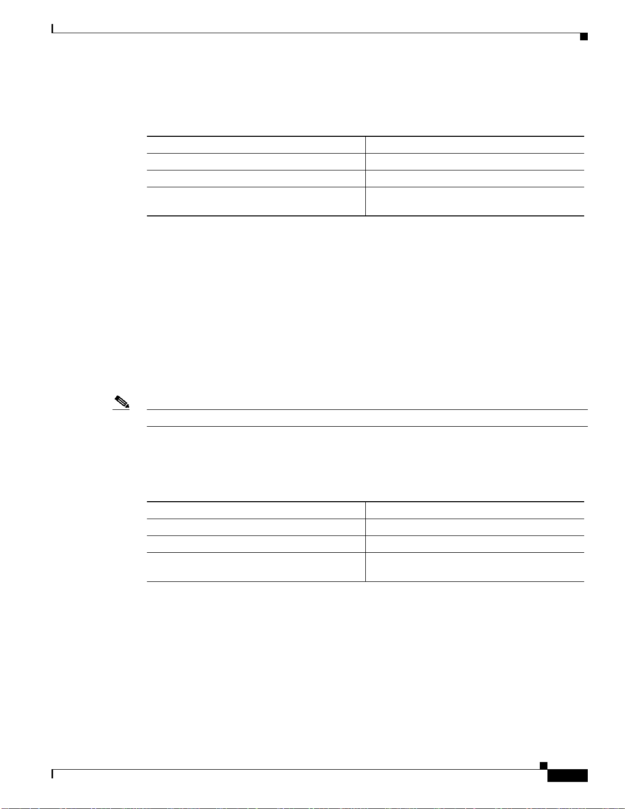
• There are four additional fields. See Table 2-3 for descriptions.
Cisco NetFlow Collector User Guide
2-39
Page 40

Reports
Chapter 2 Using the NetFlow Collector User Interface
Table 2-3 Scheduled Report Fields
Field Value Description
Scheduled
Report ID
String containing alphanumeric
characters including a hyphen (-) and
The ID to identify this type of report.
underscore (_).
Report
Frequency
Start Time A time string in the format of hh:mm:ss
Daily or Hourly. The default value is
Daily.
where hh is the hour of the day in 24 hour
notation, mm is the minute of the hour,
The frequency at which this type of report
is run.
If Start Time and End Time are specified,
the daily report will include data only for
the time range within the day.
and ss is the seconds of the minute. For
example, 13:05:00 for 1:05PM and 0
seconds.
End Time A time string in the format of hh:mm:ss
where hh is the hour of the day in 24 hour
notation, mm is the minute of the hour,
If Start Time and End Time are specified,
the daily report will include data only for
the time range within the day.
and ss is the seconds of the minute. For
example, 13:05:00 for 1:05PM and 0
seconds.
Days To Keep A positive integer no greater than 32767.
The default value is 7.
The number of days the generated reports
of this type will be kept on the server.
Reports of this type past this date will be
purged automatically.
Output Path Place-name of an existing directory. The
default value is /opt/CSCOnfc/Reports.
Specifies where reports of this type will
be stored. All reports of this type will be
written to the subdirectory (named with
the report ID) under the output path.
For example, if you use the default output
path /opt/CSCOnfc/Reports and the
report ID is foo, all reports of type foo
will be stored in
/opt/CSCOnfc/Reports/foo.
Report Type Top-N or Bottom-N Specifies whether the report shows the
Top-N or Bottom-N values as determined
by the Ordered By value selection.
2-40
Cisco NetFlow Collector User Guide
OL-11399-01
Page 41

Chapter 2 Using the NetFlow Collector User Interface
Table 2-3 Scheduled Report Fields (continued)
Field Value Description
N (maximum
Rows)
A positive integer, N, no greater than
2147483647. Default value is 10.
Ordered By Value field name The value field that determines report
IncludeRecord
Yes or No. The default value is No. Specifies whether to include the record
All
Reports
The maximum number of rows the report
should contain for each exporting device.
The total number of unique records in all
the NetFlow Collector data files being
reported can be much greater than the
number of the records you might want to
present in a report. Use this field to limit
the number of records contained in the
report.
You can sort all aggregated unique
records in descending (or ascending)
order, according to a user-specifiedvalue
field, and present the first or last N
records in the report. To show the relative
magnitude of data that is not displayed,
allrecords (not just those returned) can be
optionally aggregated into one record
with key value of All.
order. The first value field selected by
default.
with key value of All. If set to Yes, the All
record will be calculated and appear in
the report.
Displaying Scheduled Reports
You can use the web-based UI to view scheduled reports. The IDs of all types of defined reports display
in the Reports navigation tree as subfolders of the Scheduled Reports folder, as shown in Figure 2-27.
Reports generated by the Report Generate and placed in user-specifieddirectories display as children (or
leaf nodes) in the subfolders of the corresponding report type. Clicking on a report node brings up a
window with that report displayed. Reports stored in the Cisco NetFlow Collector report XML format
are formatted into tabular form. Reports stored in other formats are loaded as is and the presentation is
left to the browser.
Note Scheduled reports do not support the advanced features, such as (Filter and Drill Down) of Custom and
Common reports.
OL-11399-01
Cisco NetFlow Collector User Guide
2-41
Page 42

Reports
Chapter 2 Using the NetFlow Collector User Interface
Figure 2-27 Scheduled Reports Folder
Reporting Features
Cisco NetFlow Collector enables you to sort, graph, export, filter,and drill down on report data from the
Report window, as shown in Figure 2-22.
Cisco NetFlow Collector User Guide
2-42
OL-11399-01
Page 43

Chapter 2 Using the NetFlow Collector User Interface
Sorting and Graphing
Each column of a report supports ascending and descending sorting. Click on the column name to sort
the table on that column. Value columns support creating a bar or pie graph of the values in that column.
Click on the bar graph icon to generate a bar graph of that column’s values, as shown in Figure 2-28.
Click on the pie graph icon to generate a pie graph of that column’s values, as shown in Figure 2-29.
Figure 2-28 Sample Bar Graph
Reports
OL-11399-01
Cisco NetFlow Collector User Guide
2-43
Page 44

Reports
Chapter 2 Using the NetFlow Collector User Interface
Figure 2-29 Sample Pie Graph
Trending
Trendingreports can be launched from the Custom Report results window,as shown in Figure 2-30. This
allows you to see how one or more report values vary over time for the report period. To launch the
Trending report, select a result row then select the Trending button.
Figure 2-30 Sample Trending Graph
2-44
Cisco NetFlow Collector User Guide
OL-11399-01
Page 45

Chapter 2 Using the NetFlow Collector User Interface
Export and Print
The toolbar icons on the top right of the Report window allow you to export and print report data. Click
on the export icon to export a report in CSV or PDF format. Click on the print icon to print the report or
graph displayed in the current window.
When exporting or printing reports, you can also select which rows to include. For example, the
following dialog appears when the export icon is clicked, as shown in Figure 2-31.
Figure 2-31 Exporting Report
Status
Filter
Drill Down
Status
Use the fields at the top right of the report data to filter report data by the key values. The string entered
into the text field is treated as a regular expression for matching keys. Click Filter to apply the filter.
Clear the text field and click Filter to return to the original report.
When the original Cisco NetFlow Collector output contains more keys than were used to generate a
report, you can choose to drill down on the data by selecting a row, selecting an addition key, and
clicking Drill Down. This will generate a new report where the original keys are fixedon the valuesfrom
the selected row and the drill down key is added to break out the data.
From the Status window you can view system health information about the collector. Such information
includes running status, flows received statistics, flows missed statistics, and collector logs.
From the Cisco NetFlow Collector Main window, click the Status tab. The Status window appears, as
shown in Figure 2-32.
OL-11399-01
Cisco NetFlow Collector User Guide
2-45
Page 46

Status
Chapter 2 Using the NetFlow Collector User Interface
Figure 2-32 Status Window
From this window you can select the following:
• Control, page 2-46
• Statistics, page 2-46
• Logs, page 2-49
Control
Clicking on the Control node of the navigation tree displays the running status of the collector, as shown
in Figure 2-33. If the collector is running, there will be a button to stop the collector. If the collector is
not running, there will be a button to start the collector. The ability to start and stop the collector from
the web-based UI is useful for restarting the collector so that configuration changes can take affect. Most
operations are not available when the collector is stopped.
Figure 2-33 Control Window
Statistics
The Cisco NetFlow Collector collects port and source statistics. The following sections describe Port
Statistics and Source Statistics.
Health Monitor Statistics
Click on the Health Monitor Statistics folder of the Statistics navigation tree to display health and
performance statistics for NetFlow Collector as shown in Figure 2-34.
2-46
Cisco NetFlow Collector User Guide
OL-11399-01
Page 47

Chapter 2 Using the NetFlow Collector User Interface
Figure 2-34 Health Monitor Statistics Window
Clicking Refresh updates the statistics displayed in the window. Also, the form refreshes automatically
every 30 seconds. The table contains the following fields; each statistic contains both the current and
maximum value.
Field Description
CPU Utilization CPU utilization percentage reported by the
Disk Utilization Disk utilization percentage reported by the
Collector Memory Utilization Memory utilization percentage of the collection
Packets Processes (per second) Number of NetFlow packets processed per second
Flows Aggregated in Current Period Number of flows aggregated in the current period;
Aggregation Records in Memory Number of aggregation records in memory;
Status
operating system.
operating system for /opt/CSCOnfc/Data.
process, relative to the limit configured in
/opt/CSCOnfc/config/nfcmem.
by the collection process.
includes duplicate flows.
excludes duplicate flows.
Port Statistics
OL-11399-01
Click on the Port Statistics folder of the Statistics navigation tree to display statistics for the ports on
which the Cisco NetFlow Collector has received data. See Figure 2-35.
Figure 2-35 Port Statistics Window
Cisco NetFlow Collector User Guide
2-47
Page 48

Status
Source Statistics
Chapter 2 Using the NetFlow Collector User Interface
Clicking on Refresh updates the statistics shown. The table contains the following fields.
Field Description
Port/Protocol Port and protocol for these statistics. Forexample,
10001/udp.
Packets Number of packets received.
Received Number of flows received.
Missed Number of flows missed (estimate based on
sequence number).
Out of sequence Numberof out-of-sequence flows(estimate based
on sequence number).
Click on the Source Statistics folder of the Statistics navigation tree to display statistics for the source
devices that Cisco NetFlow Collector has received data from. Source Statistics. See Figure 2-36.
Figure 2-36 Source Statistics Window
Clicking on Refresh updates the statistics shown. The table contains the following fields.
Field Description
Device IP address from where the data was received.
Port Port and protocol
SourceID source_id (V9) or engine_type and engine_id
(other versions).
Version Version of data received.
Packets Number of packets received.
Received Number of flows received.
Missed Number of flows missed (estimate based on
sequence number).
Out of sequence Numberof out-of-sequence flows(estimate based
on sequence number).
2-48
Each row shown represents a unique combination of the Device, Port, SourceID, and NDE version.
Cisco NetFlow Collector User Guide
OL-11399-01
Page 49

Chapter 2 Using the NetFlow Collector User Interface
Logs
The logs viewable from the web-based UI are listed under the Logs folder in the navigation tree. Clicking
on a specific log loads that log file into the browser window, as shown in Figure 2-37.
Figure 2-37 Viewing Logs in Web-based UI
Status
OL-11399-01
Cisco NetFlow Collector User Guide
2-49
Page 50

Status
Chapter 2 Using the NetFlow Collector User Interface
2-50
Cisco NetFlow Collector User Guide
OL-11399-01
 Loading...