

Page 1

Cisco WAN Modeling Tools User Guide
Release 15.3.00
May 2006
Corporate Headquarters
Cisco Systems, Inc.
170 West Tasman Drive
San Jose, CA 95134-1706
USA
http://www.cisco.com
Tel: 408 526-4000
800 553-NETS (6387)
Fax: 408 526-4100
Customer Order Number:
Text Part Number: OL-10426-01
Page 2

THE SPECIFICATIONS AND INFORMATION REGARDING THE PRODUCTS IN THIS MANUAL ARE SUBJECT TO CHANGE WITHOUT NOTICE. ALL
STATEMENTS, INFORMATION, AND RECOMMENDATIONS IN THIS MANUAL ARE BELIEVED TO BE ACCURATE BUT ARE PRESENTED WITHOUT
WARRANTY OF ANY KIND, EXPRESS OR IMPLIED. USERS MUST TAKE FULL RESPONSIBILITY FOR THEIR APPLICATION OF ANY PRODUCTS.
THE SOFTWARE LICENSE AND LIMITED WARRANTY FOR THE ACCOMPANYING PRODUCT ARE SET FORTH IN THE INFORMATION PACKET THAT
SHIPPED WITH THE PRODUCT AND ARE INCORPORATED HEREIN BY THIS REFERENCE. IF YOU ARE UNABLE TO LOCATE THE SOFTWARE LICENSE
OR LIMITED WARRANTY, CONTACT YOUR CISCO REPRESENTATIVE FOR A COPY.
The Cisco implementation of TCP header compression is an adaptation of a program developed by the University of California, Berkeley (UCB) as part of UCB’s public
domain version of the UNIX operating system. All rights reserved. Copyright © 1981, Regents of the University of California.
NOTWITHSTANDING ANY OTHER WARRANTY HEREIN, ALL DOCUMENT FILES AND SOFTWARE OF THESE SUPPLIERS ARE PROVIDED “AS IS” WITH
ALL FAULTS. CISCO AND THE ABOVE-NAMED SUPPLIERS DISCLAIM ALL WARRANTIES, EXPRESSED OR IMPLIED, INCLUDING, WITHOUT
LIMITATION, THOSE OF MERCHANTABILITY, FITNESS FOR A PARTICULAR PURPOSE AND NONINFRINGEMENT OR ARISING FROM A COURSE OF
DEALING, USAGE, OR TRADE PRACTICE.
IN NO EVENT SHALL CISCO OR ITS SUPPLIERS BE LIABLE FOR ANY INDIRECT, SPECIAL, CONSEQUENTIAL, OR INCIDENTAL DAMAGES, INCLUDING,
WITHOUT LIMITATION, LOST PROFITS OR LOSS OR DAMAGE TO DATA ARISING OUT OF THE USE OR INABILITY TO USE THIS MANUAL, EVEN IF CISCO
OR ITS SUPPLIERS HAVE BEEN ADVISED OF THE POSSIBILITY OF SUCH DAMAGES.
CCSP, CCVP, the Cisco Square Bridge logo, Follow Me Browsing, and StackWise are trademarks of Cisco Systems, Inc.; Changing the Way We Work, Live, Play, and Learn,
and iQuick Study are service marks of Cisco Systems, Inc.; and Access Registrar, Aironet, BPX, Catalyst, CCDA, CCDP, CCIE, CCIP, CCNA, CCNP, Cisco, the Cisco
Certified Internetwork Expert logo, Cisco IOS, Cisco Press, Cisco Systems, Cisco Systems Capital, the Cisco Systems logo, Cisco Unity, Enterprise/Solver, EtherChannel,
EtherFast, EtherSwitch, Fast Step, FormShare, GigaDrive, GigaStack, HomeLink, Internet Quotient, IOS, IP/TV, iQ Expertise, the iQ logo, iQ Net Readiness Scorecard,
LightStream, Linksys, MeetingPlace, MGX, the Networkers logo, Networking Academy, Network Registrar, Packet, PIX, Post-Routing, Pre-Routing, ProConnect,
RateMUX, ScriptShare, SlideCast, SMARTnet, The Fastest Way to Increase Your Internet Quotient, and TransPath are registered trademarks of Cisco Systems, Inc. and/or
its affiliates in the United States and certain other countries.
All other trademarks mentioned in this document or Website are the property of their respective owners. The use of the word partner does not imply a partnership relationship
between Cisco and any other company. (0601R)
Cisco WAN Modeling Tools Guide
Copyright © 2006, Cisco Systems, Inc.
All rights reserved.
Page 3

Preface ix
Related CWM and Switch Documentation ix
Obtaining Documentation x
Cisco.com xi
Documentation DVD xi
Ordering Documentation xi
Documentation Feedback xi
Cisco Product Security Overview xii
Reporting Security Problems in Cisco Products xii
Obtaining Technical Assistance xiii
Cisco Technical Support Website xiii
Submitting a Service Request xiii
Definitions of Service Request Severity xiv
CONTENTS
CHAPTER
CHAPTER
Obtaining Additional Publications and Information xiv
1 Overview of the WAN Modeling Tools 1-1
Cisco WAN Modeling Tools Overview 1-1
Functionality of the NMT 1-2
Cisco Products Supported by the NMT 1-3
Basic Usage/Charter Functionality 1-4
Gaps 1-5
Data Translation Tools 1-6
2 Installing the Cisco WAN Modeling Tools 2-1
System Requirements 2-1
Installing the NMT 2-2
Installing the NMT on a UNIX Platform 2-2
Installing the NMT on a PC Platform 2-5
Upgrading the NMT Software 2-6
Starting the NMT 2-6
OL-10426-01, Rev. A0
Removing NMT 2-7
Installing a Cisco WAN Modeling Tools Sub-application 2-7
Installing the Cisco WAN Modeling Tools sub-applications on a UNIX Platform 2-8
Cisco WAN Modeling Tools Guide
iii
Page 4

Contents
Installing the SSI on a PC Platform 2-8
Removing Sub-applications 2-9
Troubleshooting NMT Installation 2-9
CHAPTER
3 Using the NMT 3-1
NMT Startup 3-1
NMT Menu Bar 3-2
File Menu 3-3
Configure Menu 3-4
Execute Menu 3-7
Display Menu 3-7
Report Menu 3-8
Maintenance Menu 3-9
Help Menu 3-9
Quit 3-9
Keyboard Commands 3-9
Help Keys 3-11
Message Keys 3-11
Modeling Processes 3-11
Error Checking 3-12
Troubleshooting NMT 3-13
CHAPTER
iv
4 Configuration Tables and Fields 4-1
General Table Information 4-1
Sites Table 4-2
Configuring Sites Example 4-6
Links Table 4-6
Minimal Link Table Usage 4-7
Link Special Cases 4-10
IMATM Trunks 4-10
Virtual Trunks 4-11
Voice Table 4-11
Data Table 4-14
Bursty Table 4-17
Bursty Table Special Cases 4-23
Interface Table 4-24
Feeder Table 4-26
Cisco WAN Modeling Tools Guide
OL-10426-01, Rev. A0
Page 5

Card Table 4-27
Groups and Network Table 4-28
Nodes Table 4-29
Network Settings 4-29
Model Options 4-31
Feeders 4-32
Modeling Implicit Feeders 4-32
Modeling Explicit Feeders 4-34
Obsolete Products 4-35
Networks with Access Feeders or Access Concentrators 4-36
FastPAD 4-38
Port Concentrator 4-41
Tiered Networks 4-42
Contents
CHAPTER
CHAPTER
5 NMT Execute Commands 5-1
Using the Route Command 5-1
AutoRoute 5-1
AutoRoute Least Cost Routing 5-1
Preferred and Directed Routes 5-2
PNNI Routing 5-3
Partitioned AutoRoute/PNNI Network 5-3
Fail Analysis Command 5-4
Build Sites Command 5-4
Optimize Command 5-5
NMT Command Results 5-6
6 NMT Reports 6-1
Site Report 6-1
Link Report 6-1
Network Summary Report 6-1
Link Load Report 6-2
ATM & FR Ports Report (or Bursty Data Ports Report) 6-3
Data & Voice Ports Report (or Voice & Data Ports Report) 6-3
Connection Routes Report 6-3
Failed Connections Report 6-3
Parts List Report 6-4
Resource Report/Card Statistics Report 6-4
PNNI Topology Report 6-5
OL-10426-01, Rev. A0
Cisco WAN Modeling Tools Guide
v
Page 6

Contents
View Summary 6-5
Using the Map Tool 6-5
CHAPTER
CHAPTER
7 NMT Utilities Command Line 7-1
8 NMT Map 8-1
NMT Map Startup 8-1
Navigating Though a Network View 8-3
Obtaining Link Information - Physical Links 8-5
Obtaining Link Information - Logical Links 8-5
Zooming the Map 8-6
Panning the Map 8-7
Map Color Coding 8-7
Controlling Map Displays in NMT 8-7
NMT Map Main Menu 8-8
Adding New Groups 8-10
Adding Nodes to Existing Groups 8-11
Deleting Groups 8-12
Deleting Nodes or Groups from Existing Groups 8-12
Saving Your Work 8-13
CHAPTER
CHAPTER
Retrieving Map Data Into NMT 8-14
Using the Map Tool with Fail Analysis 8-14
Using the Map Tool to Analyze Traffic Levels 8-14
9 Configuration Extraction Tool 9-1
Fields Addressed by CET 9-1
Using the CET 9-2
Other CET Commands 9-4
AIX Platform Support 9-5
Troubleshooting CET 9-5
Remote CET Extracts 9-8
Troubleshooting 9-10
10 WANDL — Third-Party Interface 10-1
Translating Between NMT and WANDL Formats 10-1
Converting NMT Configuration Files into WANDL Files 10-2
vi
Cisco WAN Modeling Tools Guide
OL-10426-01, Rev. A0
Page 7

Converting WANDL Files into NMT .cnf Files 10-4
Contents
CHAPTER
CHAPTER
I
NDEX
11 SpreadSheet Interface 11-1
NMT to Microsoft Excel 11-1
Microsoft Excel to NMT 11-4
Usage Review 11-5
SSI TroubleShooting 11-6
12 Cisco Network Designer Importer 12-1
CND PC Import Utilities 12-1
Installing the NMT2CND file 12-1
Nmt2Cnd Operating Instructions 12-2
Installing The DBF2Cnd Utility 12-2
DBF2Cnd Operating Instructions 12-3
CND PC Utilities 12-4
OL-10426-01, Rev. A0
Cisco WAN Modeling Tools Guide
vii
Page 8

Contents
viii
Cisco WAN Modeling Tools Guide
OL-10426-01, Rev. A0
Page 9

Preface
The Cisco WAN Modeling Tools User Guide provides instructions for using the WAN Modeling Tools,
a design aid for WANs. The WAN Modeling Tools consist of the following software tools:
• Network Modeling Tool (NMT). UNIX and PC versions are available.
• Map Tool to display a graphical model of network topology.
• Configuration Extraction Tool (CET) for retrieving existing topologies from the Cisco Wan Manager
(CWM) database.
• Conversion Plug-ins: the Third-Party Interface (TPI) for sharing NMT information with WANDL
and the SpreadSheet Interface (SSI) for exchanging NMT configurations with Microsoft Excel.
These tools are integrated into NMT, but are also available as UNIX stand alone commands.
• Cisco Network Designer (CND) importing tool for importing and storing topologies in a project
format.
The guide is written for anyone who operates or manages a WAN and has a general understanding of
data communications concepts, some knowledge of UNIX and/or PC desktop, and knowledge of the
interfaces used by devices connected to their WAN.
Related CWM and Switch Documentation
A Guide to Cisco Multiservice Switch Documentation ships with your product. This guide contains
general information about how to locate Cisco MGX, BPX, SES, and CWM documentation online.
These documents comprise the CWM documentation set. The first five documents are on the CWM
Documentation CD and on Cisco.com:
• Cisco WAN Manager Installation Guide, Release 15.3.00
• Cisco WAN Manager User’s Guide, Release 15.3.00
• Cisco WAN Manager SNMP Service Agent Guide, 15.3.00
• Cisco WAN Manager Database Interface Guide, Release 15.3.00
• Cisco WANDEST Installation and Reference, Release 2.7
These documents are available on Cisco.com:
• Release Notes for Cisco WAN Manager, Release 15.3.00
• Release Notes for the Cisco WAN Modeling Tools, Release 5
• Cisco WAN Modeling Tools User Guide, 15.3.00
OL-10426-01, Rev. A0
Cisco WAN Modeling Tools Guide
ix
Page 10

Obtaining Documentation
The CWM Modeling Tools and Automated Bulk Provisioning user guides are also available on their
software CDs and ordered separately.
Refer to the current CWM release notes for information on all the switch products that CWM supports
and that are certified in this release.
You can access all CWM documentation at this website:
http://www.cisco.com/en/US/products/sw/netmgtsw/ps2340/tsd_products_support_series_home.html
These documents support this release of the Cisco Multiservice Switch products and are shipped with
the product:
You can access the MGX switch documentation at this website. See MGX Switches:
Preface
• Release Notes for CWM Automated Bulk Provisioning, Release 15.3.00
• Cisco WAN Manager Automated Bulk Provisioning Guide, Release 15.3.00
• Regulatory Compliance and Safety Information for Cisco Multiservice Switch Products (MGX, BPX,
and SES)—Familiarizes you with safety precautions for your product.
• A Guide to Cisco Multiservice Switch Documentation—Describes how to find the manuals and
release notes that support multiservice switches and network management products. These
documents are available only online. This guide ships with the product.
• Installation Warning Card—Contains precautions that you should take before you insert a card into
a slot. This Warning Card ships with the product.
http://www.cisco.com/en/US/products/hw/switches/tsd_products_support_category_home.html
Refer to these MGX technical manuals as appropriate:
• For planning information if your network contains MGX and SES products—Cisco PNNI Network
Planning Guide for MGX and SES Products
• For information about installing cards and cables in the MGX chassis:
–
Cisco MGX 8850 (PXM1E/PXM45), Cisco MGX 8950, and Cisco MGX 8830 Hardware
Installation Guide, Releases 2 Through 5 for installing cards and cables in these chassis.
–
Cisco MGX 8xxx Edge Concentrator Installation and Configuration Guide for installing cards
and cables in the Cisco MGX 8230, Cisco MGX 8250, or Cisco MGX 8850 (PXM1) chassis.
• For configuring your MGX switch and processor cards:
–
Cisco MGX 8850 (PXM1E/PXM45), Cisco MGX 8950, and Cisco MGX 8830 Configuration
Guide, Release 5 for these chassis.
–
Cisco MGX 8xxx Edge Concentrator Installation and Configuration Guide for the Cisco MGX
8230, Cisco MGX 8250, or Cisco MGX 8850 (PXM1) chassis.
You can also use Cisco.com to search for any product and topic by entering a word or phrase in the
Search window. For example, you can search for “configuring MGX 8850” or “PXMIE.” By using the
Advanced Search option, you can search the entire Cisco.com or Technical Support & Documentation.
Obtaining Documentation
Cisco documentation and additional literature are available on Cisco.com. Cisco also provides several
ways to obtain technical assistance and other technical resources. These sections explain how to obtain
technical information from Cisco Systems.
Cisco WAN Modeling Tools Guide
x
OL-10426-01, Rev. A0
Page 11

Preface
Cisco.com
You can access the most current Cisco documentation at this URL:
http://www.cisco.com/univercd/home/home.htm
You can access the Cisco website at this URL:
http://www.cisco.com
You can access international Cisco websites at this URL:
http://www.cisco.com/public/countries_languages.shtml
Documentation DVD
Cisco documentation and additional literature are available in a Documentation DVD package, which
may have shipped with your product. The Documentation DVD is updated regularly and may be more
current than printed documentation. The Documentation DVD package is available as a single unit.
Registered Cisco.com users (Cisco direct customers) can order a Cisco Documentation DVD (product
number DOC-DOCDVD=) from the Ordering tool or Cisco Marketplace.
Documentation Feedback
Cisco Ordering tool:
http://www.cisco.com/en/US/partner/ordering/
Cisco Marketplace:
http://www.cisco.com/go/marketplace/
Ordering Documentation
You can find instructions for ordering documentation at this URL:
http://www.cisco.com/univercd/cc/td/doc/es_inpck/pdi.htm
You can order Cisco documentation in these ways:
• Registered Cisco.com users (Cisco direct customers) can order Cisco product documentation from
the Ordering tool:
http://www.cisco.com/en/US/partner/ordering/
• Nonregistered Cisco.com users can order documentation through a local account representative by
calling Cisco Systems Corporate Headquarters (California, USA) at 408 526-7208 or, elsewhere in
North America, by calling 1 800 553-NETS (6387).
Documentation Feedback
OL-10426-01, Rev. A0
You can send comments about technical documentation to bug-doc@cisco.com.
Cisco WAN Modeling Tools Guide
xi
Page 12

Cisco Product Security Overview
You can submit comments by using the response card (if present) behind the front cover of your
document or by writing to the following address:
Cisco Systems
Attn: Customer Document Ordering
170 West Tasman Drive
San Jose, CA 95134-9883
We appreciate your comments.
Cisco Product Security Overview
Cisco provides a free online Security Vulnerability Policy portal at this URL:
http://www.cisco.com/en/US/products/products_security_vulnerability_policy.html
From this site, you can perform these tasks:
• Report security vulnerabilities in Cisco products.
• Obtain assistance with security incidents that involve Cisco products.
Preface
• Register to receive security information from Cisco.
A current list of security advisories and notices for Cisco products is available at this URL:
http://www.cisco.com/go/psirt
If you prefer to see advisories and notices as they are updated in real time, you can access a Product
Security Incident Response Team Really Simple Syndication (PSIRT RSS) feed from this URL:
http://www.cisco.com/en/US/products/products_psirt_rss_feed.html
Reporting Security Problems in Cisco Products
Cisco is committed to delivering secure products. We test our products internally before we release them,
and we strive to correct all vulnerabilities quickly. If you think that you might have identified a
vulnerability in a Cisco product, contact PSIRT:
• Emergencies— security-alert@cisco.com
• Nonemergencies— psirt@cisco.com
Tip We encourage you to use Pretty Good Privacy (PGP) or a compatible product to encrypt any sensitive
information that you send to Cisco. PSIRT can work from encrypted information that is compatible with
PGP versions 2.x through 8.x.
Never use a revoked or an expired encryption key. The correct public key to use in your correspondence
with PSIRT is the one that has the most recent creation date in this public key server list:
xii
http://pgp.mit.edu:11371/pks/lookup?search=psirt%40cisco.com&op=index&exact=on
In an emergency, you can also reach PSIRT by telephone:
• 1 877 228-7302
• 1 408 525-6532
Cisco WAN Modeling Tools Guide
OL-10426-01, Rev. A0
Page 13

Preface
Obtaining Technical Assistance
For all customers, partners, resellers, and distributors who hold valid Cisco service contracts, Cisco
Technical Support provides 24-hour-a-day, award-winning technical assistance. The Cisco Technical
Support Website on Cisco.com features extensive online support resources. In addition, Cisco Technical
Assistance Center (TAC) engineers provide telephone support. If you do not hold a valid Cisco service
contract, contact your reseller.
Cisco Technical Support Website
The Cisco Technical Support Website provides online documents and tools for troubleshooting and
resolving technical issues with Cisco products and technologies. The website is available 24 hours a day,
365 days a year, at this URL:
http://www.cisco.com/techsupport
Access to all tools on the Cisco Technical Support Website requires a Cisco.com user ID and password.
If you have a valid service contract but do not have a user ID or password, you can register at this URL:
http://tools.cisco.com/RPF/register/register.do
Obtaining Technical Assistance
Note Use the Cisco Product Identification (CPI) tool to locate your product serial number before submitting
a web or phone request for service. You can access the CPI tool from the Cisco Technical Support
Website by clicking the Tools & Resources link under Documentation & Tools. Choose Cisco Product
Identification Tool from the Alphabetical Index drop-down list, or click the Cisco Product
Identification Tool link under Alerts & RMAs. The CPI tool offers three search options: by product ID
or model name; by tree view; or for certain products, by copying and pasting show command output.
Search results show an illustration of your product with the serial number label location highlighted.
Locate the serial number label on your product and record the information before placing a service call.
Submitting a Service Request
Using the online TAC Service Request Tool is the fastest way to open S3 and S4 service requests. (S3
and S4 service requests are those in which your network is minimally impaired or for which you require
product information.) After you describe your situation, the TAC Service Request Tool provides
recommended solutions. If your issue is not resolved using the recommended resources, your service
request is assigned to a Cisco TAC engineer. The TAC Service Request Tool is located at this URL:
http://www.cisco.com/techsupport/servicerequest
For S1 or S2 service requests or if you do not have Internet access, contact the Cisco TAC by telephone.
(S1 or S2 service requests are those in which your production network is down or severely degraded.)
Cisco TAC engineers are assigned immediately to S1 and S2 service requests to help keep your business
operations running smoothly.
To open a service request by telephone, use one of the following numbers:
OL-10426-01, Rev. A0
Asia-Pacific: +61 2 8446 7411 (Australia: 1 800 805 227)
EMEA: +32 2 704 55 55
USA: 1 800 553-2447
For a complete list of Cisco TAC contacts, go to this URL:
http://www.cisco.com/techsupport/contacts
Cisco WAN Modeling Tools Guide
xiii
Page 14

Obtaining Additional Publications and Information
Definitions of Service Request Severity
To ensure that all service requests are reported in a standard format, Cisco has established severity
definitions.
Severity 1 (S1)—Your network is “down,” or there is a critical impact to your business operations. You
and Cisco will commit all necessary resources around the clock to resolve the situation.
Severity 2 (S2)—Operation of an existing network is severely degraded, or significant aspects of your
business operation are negatively affected by inadequate performance of Cisco products. You and Cisco
will commit full-time resources during normal business hours to resolve the situation.
Severity 3 (S3)—Operational performance of your network is impaired, but most business operations
remain functional. You and Cisco will commit resources during normal business hours to restore service
to satisfactory levels.
Severity 4 (S4)—You require information or assistance with Cisco product capabilities, installation, or
configuration. There is little or no effect on your business operations.
Obtaining Additional Publications and Information
Preface
Information about Cisco products, technologies, and network solutions is available from various online
and printed sources.
• Cisco Marketplace provides a variety of Cisco books, reference guides, and logo merchandise. Visit
Cisco Marketplace, the company store, at this URL:
http://www.cisco.com/go/marketplace/
• Cisco Press publishes a wide range of general networking, training and certification titles. Both new
and experienced users will benefit from these publications. For current Cisco Press titles and other
information, go to Cisco Press at this URL:
http://www.ciscopress.com
• Packet magazine is the Cisco Systems technical user magazine for maximizing Internet and
networking investments. Each quarter, Packet delivers coverage of the latest industry trends,
technology breakthroughs, and Cisco products and solutions, as well as network deployment and
troubleshooting tips, configuration examples, customer case studies, certification and training
information, and links to scores of in-depth online resources. You can access Packet magazine at
this URL:
http://www.cisco.com/packet
• iQ Magazine is the quarterly publication from Cisco Systems designed to help growing companies
learn how they can use technology to increase revenue, streamline their business, and expand
services. The publication identifies the challenges facing these companies and the technologies to
help solve them, using real-world case studies and business strategies to help readers make sound
technology investment decisions. You can access iQ Magazine at this URL:
xiv
http://www.cisco.com/go/iqmagazine
• Internet Protocol Journal is a quarterly journal published by Cisco Systems for engineering
professionals involved in designing, developing, and operating public and private internets and
intranets. You can access the Internet Protocol Journal at this URL:
http://www.cisco.com/ipj
Cisco WAN Modeling Tools Guide
OL-10426-01, Rev. A0
Page 15

Preface
Obtaining Additional Publications and Information
• World-class networking training is available from Cisco. You can view current offerings at
this URL:
http://www.cisco.com/en/US/learning/index.html
OL-10426-01, Rev. A0
Cisco WAN Modeling Tools Guide
xv
Page 16

Obtaining Additional Publications and Information
Preface
xvi
Cisco WAN Modeling Tools Guide
OL-10426-01, Rev. A0
Page 17

Overview of the WAN Modeling Tools
This chapter provides an overview of the applications that make up the Cisco WAN Modeling Tools, and
of the Cisco products they support.
Cisco WAN Modeling Tools Overview
Cisco WAN Modeling Tools includes the following tools:
• The Network Modeling Tool (NMT)
• The Configuration Extraction Tool (CET)
• The Third-Party Interface (TPI)
• The Spread Sheet Interface (SSI)
The NMT is the primary application of the Cisco WAN Modeling Tools. NMT verifies the provisioning
and predicts the routing behavior of the network. NMT supports the following Cisco MSSBU ATM
platforms:
CHAPTER
1
• MGX series
• BPX series
• IGX series
For each major switch software release, NMT verifies the physical and logical provisioning of the front
and back cards that support the specified topology. NMT also verifies connection routing and rerouting
capabilities of each supported switch in the network.
The CET, SSI, and TPI tools enable the exchange of information between the NMT and other
applications. These tools provide interfaces to CWM, Excel, and WANDL.
OL-10426-01, Rev. A0
Cisco WAN Modeling Tools Guide
1-1
Page 18
Functionality of the NMT
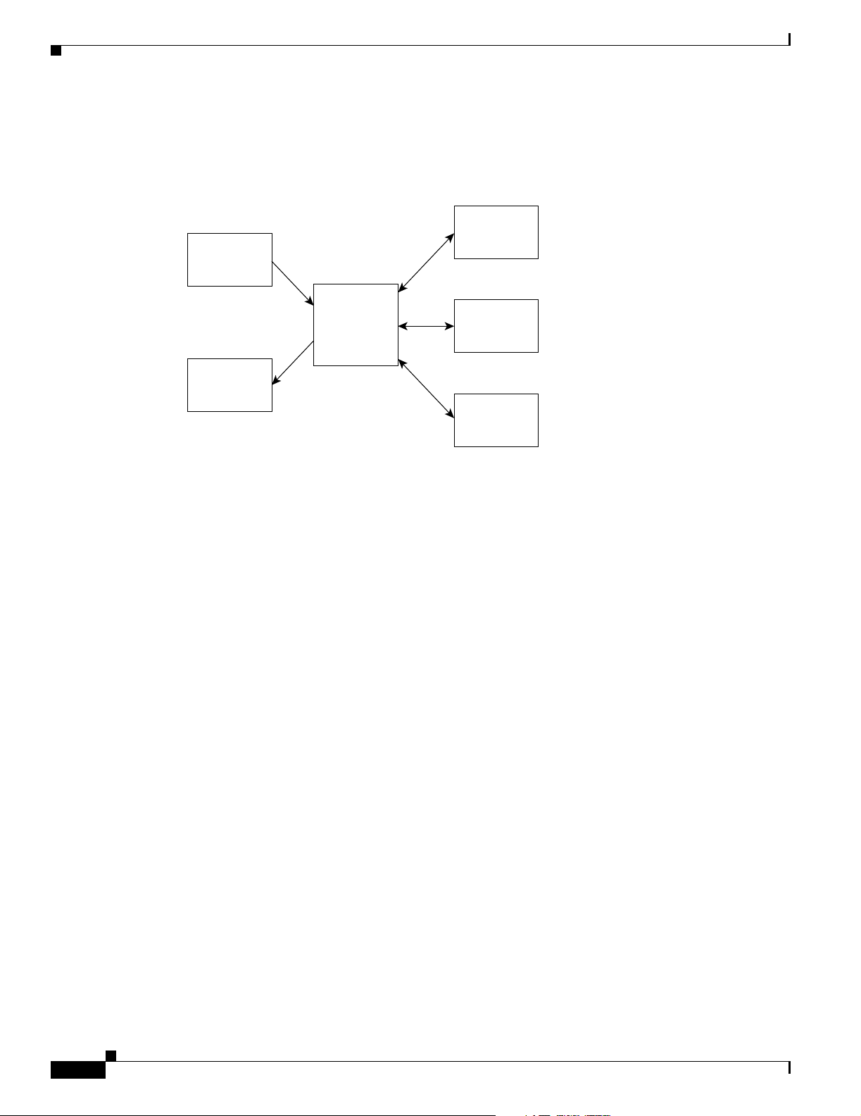
Figure 1-1 shows the relationship between the applications that make up the Cisco WAN Modeling
Tools.
Figure 1-1 Relationship between the Cisco WAN Modeling Tools
CWM
CND
NMT
netowork
topology
data
Chapter 1 Overview of the WAN Modeling Tools
EXCEL
NMT
WANDL
49072
Functionality of the NMT
The NMT is a menu driven application that enables you to model the behavior of both simple and
complex networks. The program processes information provided by you and returns a proposed
configuration. This configuration can then be modified and reprocessed to add redundant links, support
additional sites, and so forth. You can also perform failure analysis of the network model by failing
selected links and then evaluating the rerouting capability of the remaining links. The NMT allows you
to interface to WANDL and other systems to further optimize the design.
Only a few fields need to be completed in order for the NMT to generate a configuration. To create the
best configuration possible,. you should have extensive knowledge of computer networks, including
ATM and Frame Relay networks. In addition, entering precise values for optional fields will help the
NMT provide you with a precise parts list that you can use to order Cisco products.
Once the NMT processes the data, it provides configuration information in the following form:
• Updated tables—Modifies your configuration tables as necessary to create a working configuration.
• Reports—Provides a series of reports that describe links, nodes, part numbers, costs, and so on.
• Graphical display—Displays your network design graphically with node icons and maps.
• Import/Export—Displays data imported/exported to other systems.
The NMT always selects the newest available parts for a function, based on the software release you
specify. You can explicitly request older cards from the input tables. Some obsolete parts are not
supported.
1-2
Cisco WAN Modeling Tools Guide
OL-10426-01, Rev. A0
Page 19

Chapter 1 Overview of the WAN Modeling Tools
Cisco Products Supported by the NMT
New functionality is added in each release of the NMT to accurately reflect the current capabilities of
the following Cisco equipment:
• MGX 8850, MGX 8830, and MGX 8950 switches—Enables a wide range of user services to be
supported by the BPX service node. Interfaces supported by the NMT include the following:
–
Frame Relay
–
ATM User-Network Interface (UNI)
–
Circuit emulation
–
n x T1/E1 inverse multiplexing for ATM (IMATM AUSM-8) UNI
–
3T3 interface using the SRM-3T3 module
• MGX 8220, MGX 8230, and MGX 8250 edge concentrators—MGX Edge concentrators enable a
wide range of user services to be supported by the BPX service node. Interfaces supported by the
NMT include the following:
–
Frame Relay
Cisco Products Supported by the NMT
–
ATM User-to-Network Interface (UNI)
–
Circuit emulation
–
n x T1/E1 inverse multiplexing for ATM (IMATM AUSM-8) UNI
–
3T3 interface using the SRM-3T3 module
• BPX switch—A standards based high-capacity (9.6 Gb) broadband ATM switch that provides
backbone ATM switching and delivers a wide range of user services. Fully integrated with the IPX
and IGX switches, the BPX switch provides broadband ATM services when ASI and BXM cards are
used. It also provides a variety of narrowband services; these services are provided by tiered network
configurations that use IPX switches and MGX 8220 feeders.
The BPX switch supports the high density Broadband Switch Module (BXM) cards that provide
standard interfaces for connecting to cell-based equipment by way of the ATM User-Network
Interface (UNI).
–
BXM DS3/E3 supports E3/DS3 native ATM access and trunk ports.
–
BXM 155 supports OC-3/STM-1 native ATM access and trunk ports.
–
BXM 622 supports OC-12/STM-4 native ATM access and trunk ports.
BXM cards also support ATM Frame Relay networks and services and enables configuration of
permanent virtual circuits (PVCs) or switched virtual circuits (SVCs) for the following defined
service classes:
–
Constant bit rate (CBR)
–
Variable bit rate (VBR)
OL-10426-01, Rev. A0
–
Unspecified bit rate (UBR)
–
Available bit rate (ABR)
• SES PNNI Controller—Attaches to a BPX switch to provide Private Network-to-Network Interface
(PNNI) signaling and routing for the establishment of ATM switched virtual circuits (SVCs) and soft
permanent virtual circuits (SPVCs) over a BPX 8600 wide area network (WAN). Features supported
by the NMT include PNNI Routing, resource partitioning, and shelf provisioning.
Cisco WAN Modeling Tools Guide
1-3
Page 20

Basic Usage/Charter Functionality
• IGX switch—A multi-service ATM networking switch that provides interfaces to support legacy and
emerging broadband applications. It supports ATM technology over subrate, narrowband E1 and T1,
and broadband E3 and T3 trunks. The IGX switch is used as the basis for a leased-line campus,
metropolitan area network (MAN) and WAN network, as an intelligent access device to high
speed-public digital services such as ATM, in a hybrid application using both, and as a WAN service
switch.
• Generic Node -- The NMT allows you to create your own node type for an ATM switch or feeder.
Use the node table to provide the high level specifications for the WAN product.
• Obsolete Equipment -- The NMT models obsolete equipment that users may encounter in CWM
extracts, and need to model for upgrade considerations. The following obsolete platforms are
modeled:
IPX switch, 3810 feeder, FastPad feeder, Port Concentrator Shelf Feeder
Basic Usage/Charter Functionality
The NMT models the WAN network using a classic node, link, and demand model. The nodes are the
sites in the site table, which are provisioned as Cisco MSSBU WAN switches. The links are the inter
switch trunks in the link table. The connections are specified in the voice, data, and bursty table.
The model provisions the network using the latest Cisco equipment, unless otherwise specified. The
model will verify that the network will route all connections, or will report on what resources have been
exceeded.
Chapter 1 Overview of the WAN Modeling Tools
The NMT tool predicts the behavior of a WAN network that uses Cisco WAN switches (MGX, BPX and
IGX product series) as follows:
1. the user specifies the site locations and switch types, the links, and the connections in the network.
2. the NMT uses the AutoRoute and PNNI routing algorithms identical to those in the products.
3. based on the Connection Admission Control (CAC) parameters, the NMT verifies that the links and
connections can be provisioned, and that the connections can be routed.
4. the WAN network is modeled at the chassis, front card, and back card granularity level.
Note All connections used by the NMT are ATM connections, with the exception of some legacy IGX voice
and data services.
Keep the following in mind when you use the NMT:
• The NMT provides the primary reason any connections cannot be provisioned or routed, based on
the CAC rules.
• The NMT does not do discrete simulation, and no real time statistics are involved in the modeling.
• The NMT address the following real time issues only:
–
delay estimate
–
requirements specified in the CAC.
• The NMT verifies the connections routed in the base state
1-4
• The NMT verifies which connections will re-route under any network failure scenario.
Cisco WAN Modeling Tools Guide
OL-10426-01, Rev. A0
Page 21

Chapter 1 Overview of the WAN Modeling Tools
• The NMT extracts the network topology and connection parameters from Cisco WAN Manager.
The NMT handles changes in the CWM DB schema, so these changes are invisible to the user. CWM
coded values are translated to more usable strings, and tables are merged so in NMT, there is 1 table
per network element.
• The NMT translates topology data to and from MS Excel data. The NMT tables are translated to
DBASE3 format and a MS Excel macro is provide for creating a file of spreadsheets for each table.
• NMT translates the topology data to and from the WANDL format for use by their NCAPS tool.
• PNNI CAC parameters are not as granular as they are in the product. For example, some parameters
are network specific.
• A 10 character node naming limitation is imposed. CWM provides translation for node naming.
Gaps
The following features are not supported by the NMT:
• XPVCs
• Voice traffic channel mapping entering the network for VISM/VXSM cards
Gaps
• IP traffic entering the network for RPM cards
• LVC resource support for RPM cards
• Port Partitioning by COS
• Priority bumping in AutoRoute
• VXSM card and connections terminated on that card
• PPP types of traffic on MPSM-16T1E1 cards
• MFR links and connections on MPSM-T3E3-155 cards
• Cisco MGX 8880 node (not supported by CWM)
OL-10426-01, Rev. A0
Cisco WAN Modeling Tools Guide
1-5
Page 22

Data Translation Tools
Data Translation Tools
The NMT Data Translation Tools use data exchanged between the NMT and other network design
software aides to create a complex network model. These tools allow the NMT to interface with other
Cisco products as well as third-party products. Table 1 - 1 describes the data translation tools.
Table 1-1 Data Translation Tools
NMT WAN Modeling Tool Description
Configuration Extraction Tool (CET) Reads the database of a Cisco Wan Manager
Third Party Interface (TPI) conversion
plug-in
SpreadSheet Interface (SSI) conversion
plug-in
Cisco Network Designer (CND) import tool Loads an NMT into the CND as a project.
Chapter 1 Overview of the WAN Modeling Tools
(CWM) system, and creates an NMT
configuration file with all critical topology
and connection information. For further
description, see Chapter 10, “Configuration
Extraction Tool.”
Translates NMT Data into WANDL format.
WANDL is a design product that helps you
optimize generic networks. TPI also provides
translation from WANDL-to-NMT
configuration files. for more information, see
Chapter 11, “Third Party Interface.”
Translates the NMT configuration file tables
into standard DBF and XLS formatted files,
for use in other systems. It also supports an
EXCEL XLS interface for entering,
modifying, and analyzing integer data.
Several NMT reports are also available in
DBF and XLS. For more information, see
Chapter 12, “SpreadSheet Interface.”
The CND provides low level local
configuration of each site on a network, and
generates graphic displays and a Bill of
Materials (BOM).
1-6
Cisco WAN Modeling Tools Guide
OL-10426-01, Rev. A0
Page 23

CHAPTER
Installing the Cisco WAN Modeling Tools
This chapter provides instructions for installing the following Cisco WAN Modeling Tools:
• the Network Modeling Tool (NMT)
• the Configuration Extraction Tool (CET)
• the Third-Party Interface (TPI) Conversion Plug-in
• the SpreadSheet Interface (SSI) Conversion Plug-in
This chapter contains the following sections:
• System Requirements
• Installing the NMT
• Upgrading the NMT Software
• Starting the NMT
• Removing NMT
• Installing a Cisco WAN Modeling Tools Sub-application
2
• Removing Sub-applications
• Troubleshooting NMT Installation
Note Check the Cisco WAN Modeling Tools Release Notes for changes in the installation process.
System Requirements
NMT, CET, TPI, and SSI run on Solaris 2.6 or later. NMT runs under many configurations, including
SPARC IPX, LX, 5, 10, 20, and Ultra. Hardware requirements depend on the size of the model you are
creating. A typical setup includes:
• Minimum 16 MB of memory
• CD ROM
• 535-MB SCSI disk or larger
The PC version of NMT runs on Windows 98, Windows 99,Windows 2000, and Windows NT.
OL-10426-01, Rev. A0
Cisco WAN Modeling Tools Guide
2-1
Page 24

Installing the NMT
Installing the NMT
This section explains how to install the Cisco WAN Modeling Tools software and link it to your project
directories. This procedure also installs any subapplications (CET, TPI, and SSI) that came with your
copy of the NMT software. If you want to install only the subapplications, refer to the “Installing a Cisco
WAN Modeling Tools Sub-application” section later in this chapter.
The NMT Product provides both a UNIX and PC version of the NMT tool. To install the NMT on a UNIX
platform, see the “Installing the NMT on a UNIX Platform” section that follows. To install the NMT on
a PC platform, see the “Installing the NMT on a PC Platform” section later in this chapter. The
differences between UNIX and PC version of the NMT are as follows:
• The PC version of NMT uses F5 for choice list, UNIX version uses HELP or F12.
• The PC version of NMT has no support to launch the MAP command.
Note CNF files from either platform can be read by the other. For example, CNF files from a PC version of
NMT can be read by a UNIX version of NMT, and vice-versa.
Chapter 2 Installing the Cisco WAN Modeling Tools
Installing the NMT on a UNIX Platform
To run NMT on Unix platforms, you need to install the software first. Install the software once for each
release platform. Once the software is installed, you need to create a working directory from which you
will launch NMT.
Load the NMT Software
Use the following procedure to create a dedicated subdirectory that will store the NMT software. The
installation process creates a subdirectory name and a release number. For example:
/usr/users/NMT/151
Note Multiple NMT feature releases can co-exist on the UNIX platform. If a maintenance upgrade is done,
the upgraded NMT release replaces the previous release.
To create the software installation directory, perform the following steps.
Step 1 Log into the account that will own the NMT software.
Step 2 Create a dedicated directory where the NMT releases are stored.
Step 3 Verify that you are in the correct directory by entering the following command:
pwd
2-2
The path with the release number is the same path you will use when you create a working directory.
Cisco WAN Modeling Tools Guide
OL-10426-01, Rev. A0
Page 25

Chapter 2 Installing the Cisco WAN Modeling Tools
Step 4 If you are installing from a cd on a Solaris platform, perform the following steps:
a. Enter the following command:
volcheck
b. Enter the following command:
Note cp /cdrom/nmt151/install/151.tar.Z
If this step fails because the file is not found, substitute nmt151#1 for nmt151.
c. Enter the following command:
uncompress 151.tar
d. Enter the following command:
tar xf 151.tar
This creates the 151 directory containing all the software.
Creating a Working Directory
Installing the NMT
Use the following procedure to link the NMT software to working or project directories.
Note You need to perform this procedure only once. Once you have created a working directory, you can
launch the NMT from the working directory.
Step 1 Log into the account that will own the working NMT directory.
Note The account that owns the working directory can be the same account that owns the software directory,
or it can be a different account.
Step 2 Create the working directory name:
mkdir project_name
Step 3 Move to the subdirectory you just created:
cd project_name
Step 4 Make sure you are running in c shell. If you are not, enter the following command:
csh
Step 5 Link the project directory to the NMT release:
OL-10426-01, Rev. A0
a. Set the environment variable NMTHOME to the path of the software directory and release. For
example:
setenv NMTHOME /usr/users/NMT/151
b. Execute the following command:
$NMTHOME/nmtlink
Cisco WAN Modeling Tools Guide
2-3
Page 26
Installing the NMT
Chapter 2 Installing the Cisco WAN Modeling Tools
The NMT files are linked or copied to the project_name directory. This links NMT and all the
plug-ins (including TPI, SSI, and CET). To link in NMT without the plug-ins, enter the following
command:
$NMTHOME/nmtlink -nmt
Note Cisco recommends that you do not link NMT without the plug-ins.
Note NMTcreates a directory under your home path called tmp. If you want NMT to use a
different directory than tmp for scratch work, you can specify it with the full path by using
the environment variable NMTTMP.)
Note Cisco recommends that you periodically remove old files from the tmp/scratch work
directory. NMT must not be running when you remove files from this directory.
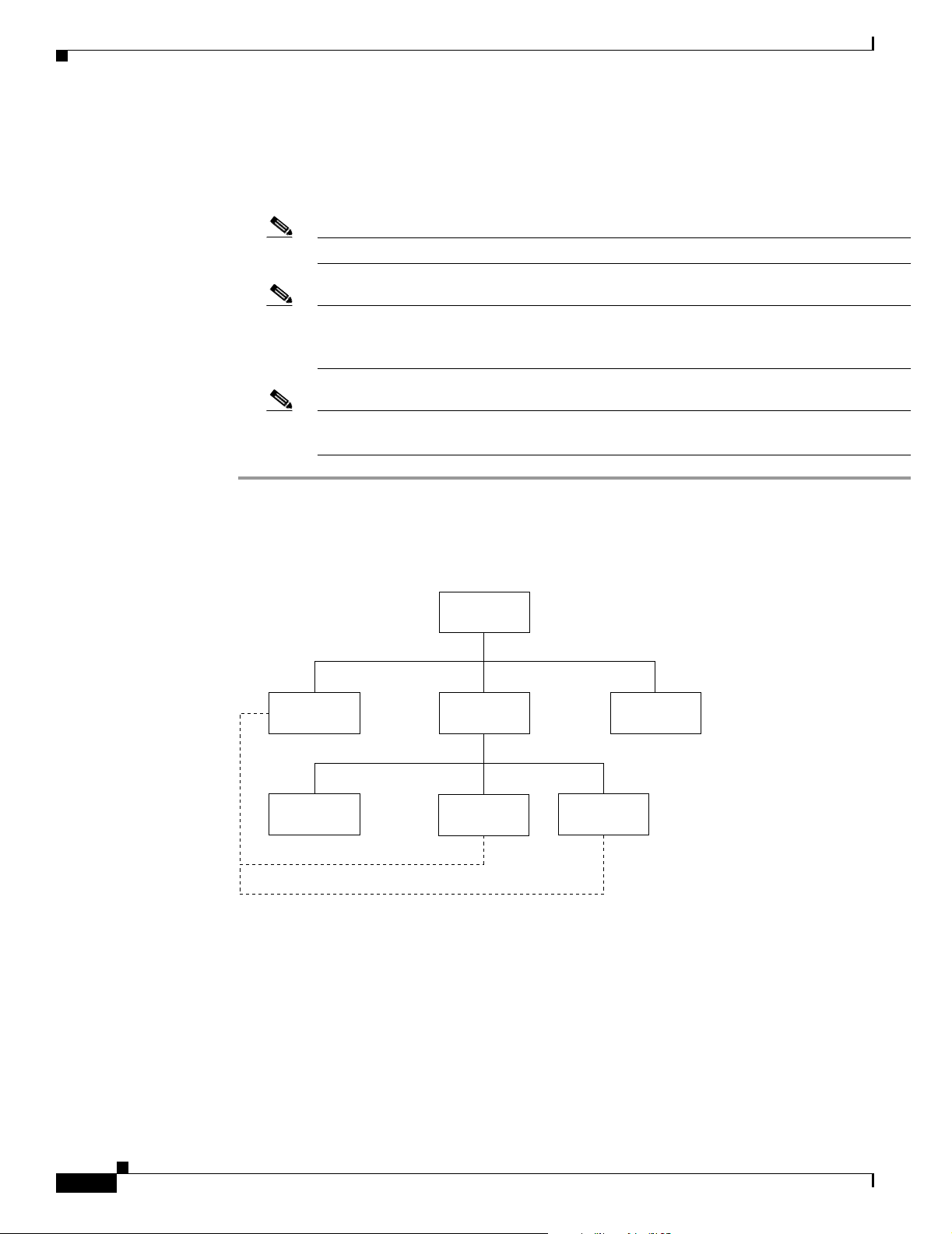
Figure 2-1 depicts the relationship between the NMT software, user, and project accounts.
Figure 2-1 Example of suggested NMT Directory Structure
usr/users
NMT
tmp
User_1
Project
Project 2
User_2
link
S6034
2-4
Cisco WAN Modeling Tools Guide
OL-10426-01, Rev. A0
Page 27

Chapter 2 Installing the Cisco WAN Modeling Tools
Installing the NMT on a PC Platform
To install NMT on the PC, follow these steps:
Step 1 Run the provided nmt installing exe file, which is a self extracting ZIP file. The file is called
‘nmt_inst.exe’ and is in the PC directory. You can either run it directly from your CD drive on the PC,
or transfer it from your UNIX installation to your PC and then run it.
Step 2 The zip file will unzip in c:\nmt by default. It is recommend you keep this as the NMT installation
directory. If you accept this selection, move to step 3. If you wish to change the installation directory,
use one of the procedures that follow.
To change the installation directory on a Windows 2000 system, follow these steps:
a. Enter the cd command to get to the Advanced directory, as shown in the following example:
My Computers/Control Panel/System/Advanced.
b. Click “Environment Variables.”
c. Click “New” and add the environment variable with the name NMTHOME, and set the value to the
directory you specified when installing the compressed file.
Installing the NMT
To change the installation directory on earlier windows systems:
a. Add the lines in the file autoexec.add to the end of your autoexec.bat file. The autoexec.add file is
in the c:\nmt default directory, and the autoexec.bat is found in the c: main directory.
b. Change the drive and directory of NMTHOME to the path you entered for the unzip command.
c. Reboot your machine before running NMT.
Step 3 Install the shortcut.
a. Open Explorer, go to \nmt\install and then to the sub directory of the operating system on your PC.
b. Drag and drop the Cisco WAN Modeling Tool shortcut to the background windows screen.
To create a short cut from scratch, follow these steps:
a. Use Explorer to drag and drop the file c:\nmt\install\nmt.exe to the background.
b. Right mouse click on the icon for properties.
c. Set start in to the recommended C:\nmt†ata, which will be the default directory for storying your
NMT files.
If you want to store your NMT data elsewhere, you can reset this. Select change icon, and then browse.
Select the file c:\nmt•in\nmt_icon.exe and pick the icon on the left.
Step 4 Click the Cisco WAN Modeling Tool icon to start NMT. Alternatively, you can start NMT by running
c:\nmt\nmt.exe.
OL-10426-01, Rev. A0
Cisco WAN Modeling Tools Guide
2-5
Page 28

Upgrading the NMT Software
Upgrading the NMT Software
NMT feature releases have unique sub directory names. The installation of a new feature release requires
the creation or alteration of the working directories. Maintenance releases, however, use the same
software directory you created in the previous section. The working directories automatically use the
upgrade through UNIX links to the software.
Use the following procedure to perform a maintenance upgrade of NMT software on a UNIX system.
Step 1 Enter the cd <directory> command to log onto the same account that was used to initially install the
software, as shown in the following example:
cd /usr/users/NMT
Step 2 Copy the compressed tar file 151.0.tar.Z to the same directory in which the release was initially installed.
Step 3 Enter the uncompress <filename> command to uncompress the file, as shown in the following example.
uncompress 151.0.tar
Chapter 2 Installing the Cisco WAN Modeling Tools
Step 4 Enter the tar xf <filename> UNIX command to untar the file as shown in the following example:
tar xf 151.0.tar
Starting the NMT
Use the following steps to run the NMT and any NMT UNIX commands.
Note Always enter the commands in the NMT working directory.
Step 1 If you are on a Cisco StrataView platform, while logged in as Cisco Wan Manager (CWM) and in the
svplus directory, enter the xhost + command to grant xwindows permission. (This can be done from the
console window or an xterm window.)
xhost +
Note You may want to add the xhost + command to the svplus.login file.
Step 2 Enter your user name and enter your password to log in to your user home directory. For example,
/usr/users/my_name.
2-6
Cisco WAN Modeling Tools Guide
OL-10426-01, Rev. A0
Page 29

Chapter 2 Installing the Cisco WAN Modeling Tools
Step 3 Enter the cd command to move to one of your project directories:
cd
project_name
Step 4 Enter the nmt command to start NMT:
nmt
Note Use the nmt -d command to start the program if you need to modify system parameters to ranges
outside the scope of the current product line. This option adds two additional selections to the
Execute menu: Internal Set for Switches/Links and Network Internal Setting.
Removing NMT
The nmtrel command removes all NMT subcomponents from the program.
Removing NMT
Installing a Cisco WAN Modeling Tools Sub-application
This section provides instructions for installing the following Cisco WAN Modeling Tools
sub-applications:
• the Configuration Extraction Tool (CET)
• the Third Party Interface (TPI)
• the SpreadSheet Interface (SSI)
To install the sub-applications on a UNIX platform, see the “Installing the Cisco WAN Modeling Tools
sub-applications on a UNIX Platform” section that follows. To install the SSI on a PC platform, see the
“Installing the SSI on a PC Platform” section, later in this chapter.
Note This procedure is necessary only if you used the -NMT option with NMTlink.
The procedures in the sections that follow are for accessing, loading, and linking the applications to
project directories.
OL-10426-01, Rev. A0
Cisco WAN Modeling Tools Guide
2-7
Page 30

Chapter 2 Installing the Cisco WAN Modeling Tools
Installing a Cisco WAN Modeling Tools Sub-application
Installing the Cisco WAN Modeling Tools sub-applications on a UNIX Platform
Use the following procedure to install a Cisco WAN Modeling Tools sub-application on a UNIX
Platform.
Step 1 Go to a working directory where you have run nmtlink.
Step 2 Set up a UNIX environment variable for CET, TPI, or SSI.
setenv [nmt_path]
nmt_path is the path to the version of the NMT software you are using.
Step 3 Link the project directory to the NMT release:
For CET: $CETHOME/cetlink
For TPI:
For SSI:
$TPIHOME/tpilink
$SSIHOME/ssilink
Installing the SSI on a PC Platform
Install the Spread Sheet Interface on the PC regardless of whether you use the PC or UNIX version of
NMT.
To install SSI on a PC, complete the following steps:
Step 1 Transfer the following files to your PC:
• SSI—NMT Excel macro file. This macro converts DBF formatted NMT tables into an Excel
spreadsheet, and vice-versa.
• SSIDOSKT.TAR—Archive file of SSI DOS utilities tar.exe; DOS version of UNIX tar command.
These optional utilities support the transferring and uncompacting of data.
Note Use binary mode when transferring SSI and SSIDOSKT.TAR to your PC.
Step 2 Copy the file SSI to the XLStart subdirectory of your Excel 5.0 (or higher) installation. It can be installed
in any Windows environment.
Note In most PC Environments, Excel will be in the directory c:\program files\Microsoft
Office\Office\XLstart.
Step 3 Copy the file to the xlstart subdirectory of the Excel product.
This Macro gives you the NMT_Load, NMT_Unload and NMT_PrettySheet commands.
2-8
Note You do not need to do Step 4 and Step 5 if you are not going to use the tar file for your NMT data.
Cisco WAN Modeling Tools Guide
OL-10426-01, Rev. A0
Page 31

Chapter 2 Installing the Cisco WAN Modeling Tools
Step 4 If you are going to use the tar file for your NMT data, copy tar.exe and SSIDOSKT.TAR to a DOS
working directory.
Step 5 Enter the command 'tar xvf SSIDOSKT.TAR to un-archive the data.
Removing Sub-applications
This section provides instructions for removing the following sub-applications on a UNIX platform:
• the Configuration Extraction Tool (CET)
• the Third Party Interface (TPI)
• the SpreadSheet Interface (SSI)
Remove individual applications by running the following commands:
• cetrel removes CET from your ID.
• tpirel removes TPI from your ID.
• ssirel removes SSI from your ID.
Removing Sub-applications
Note Enter the nmtrel command to remove all applications from your ID.
Troubleshooting NMT Installation
The table below describes a common NMT Installation problems and what can be done about them.
Symptom The command nmt fails, returns message:
xterm not found.
Probable Causes Unix is not configured for xterm.
Solution Have a UNIX administrator provide xterm support for your account.
Symptom Cannot write cnf files or reports.
Cannot update the map.
Probable Causes No write permission.
Solution Make sure your account has write permission to your working directory.
OL-10426-01, Rev. A0
Symptom NMT fails and displays the following error message:
Error: Cannot open display <IP-ADDRESS:00>
Probable Causes No remote display permission. Site is unreachable.
Solution Check network connectivity. If you are using a dial-up line, remote GUI
display may be impossible.
Cisco WAN Modeling Tools Guide
2-9
Page 32

Troubleshooting NMT Installation
Symptom NMT displays the following error message:
Probable Causes You are running NMT remotely, and the server is not granting you
Solution Enter the XHost + command the console on the displaying platform.
Symptom NMT displays the following error message:
Probable Causes IP address is unreachable.
Solution check address and network connectivity.
Chapter 2 Installing the Cisco WAN Modeling Tools
Xlib: Connection to <IP-ADDRESS:00> refused by server.
Xlib: Client is not authorized to connect to server.
ERROR, cannot open display <IP-ADDRESS:00>.
permission.
Xterm X+ error: Can’t open display
<IP-ADDRESS:00>
2-10
Cisco WAN Modeling Tools Guide
OL-10426-01, Rev. A0
Page 33

CHAPTER
3
Using the NMT
This chapter provides instructions for using the NMT interface, presents an overview of the modeling
process, and lists NMT commands that update or extract information from NMT configuration files. This
chapter contains the following sections:
• NMT Startup
• NMT Menu Bar
• File Menu
• Keyboard Commands
• Modeling Processes
• Error Checking
• Work F l ow
The NMT models a network based on your input. Using your input about the network you want to model,
the NMT helps identify the hardware needed by provisioning the chassis with front cards and back cards.
The NMT routes the connections using the same software as the WAN switches, based on the Connection
Admission Control (CAC). The NMT is aware of all physical and logical constraints that would prevent
a connection or a trunk from being provisioned or routed. NMT is also aware of the different features
and constraints in each major switch software release.
Connection routing can be verified in the network's basic state. The connection re-routing can be verified
for any failure scenario. Simulation of failure of all network elements can verify the network's resiliency.
NMT Startup
If you are running NMT on a UNIX platform, start the NMT by entering the command nmt. This
launches an xterm window for the NMT interface (Figure 3-1).
If you are running NMT on a PC platform, start the NMT by clicking on the nmt.exe file located in the
NMT/bin subdirectory. This launches an xterm window for the NMT interface
OL-10426-01, Rev. A0
Cisco WAN Modeling Tools Guide
3-1
Page 34

NMT Menu Bar
Chapter 3 Using the NMT
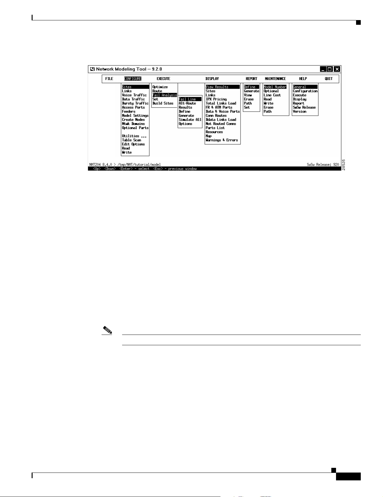
Figure 3-1 NMT Main Window
NMT Menu Bar
The menus in the NMT main window contain selections for inputting data that describes the existing or
proposed network. These menus also provide selections for generating optimized configurations and
many different types of reports. (See Figure 3-2.) The menus are as follows:
• File—Contains choices for opening, closing, deleting, and saving your file. It also provides options
for importing and exporting files to other formats, changing paths, and viewing a summary of your
network.
• Configure—Contains choices for describing the network model, including site names, links, and
traffic types.
• Execute—Provides choices for analyzing and optimizing the network model.
• Display—Shows predefined reports describing the sites, links, required hardware, error messages
and warnings, and much more. Includes a map tool selection for creating a graphical representation
of your network.
• Report—Provides options for generating, defining, and displaying reports.
• Maintenance—Includes selections for modifying prices and part names and for specifying line
costs.
• Help—Provides information about how to use the program and describes many of the menus and
menu items in the NMT.
• Quit—Exits the NMT application.
3-2
Cisco WAN Modeling Tools Guide
OL-10426-01, Rev. A0
Page 35
Chapter 3 Using the NMT
File Menu
Figure 3-2 NMT Design Menu (All Menu Options Displayed)
When you highlight a menu item, a one-line description of the selection is displayed beneath the menu.
The NMT Design menus and their menu items are further described in the sections that follow.
File Menu
You can access the following commands from the File menu in the Network Design Tools window:
• New—Opens a new file. Clears all read and entered topology information.
• Open—Opens a previously saved file.
• Save—Saves the current configuration.
• save as...—Saves the current configuration under a new name.
• Import—Reads configuration data from other formats and imports it into the current file.
–
DBF—Import topology from DBF tables and the SSI MS Excel Interface.
–
WANDL—Read the topology from the set of WANDL files specified by their SPEC file.
–
MAP—Read any changes made with the Map interface back into the CNF file.
Note Save changes in the map interface before importing that Map interface into the CNF file.
• Export—Writes the configuration data to other formats.
–
DBF—Output table in DBF format for SSI MS Excel Interface.
–
WANDL—Output topology in WANDL format for Further optimization and analysis.
–
CSV—Output Tables in comma separation values.
• Read 2nd CNF—Merges all or some tables of one configuration file into another. This enables you
to perform certain operations on two separate configuration (CNF) topologies. For example,
updating the fields in one CNF table automatically updates the same fields in other CNF tables. You
can also use this option to compare two CNF files.
OL-10426-01, Rev. A0
• Delete—Erases the configuration file.
• Change Path
—Changes the current directory path.
Cisco WAN Modeling Tools Guide
3-3
Page 36

File Menu
• View Summary—Shows a summary of the current topology.
• Report Site—Shows a summary of a specific site.
Saving Configurations
Save your configuration regularly. The directory path is shown in the bottom left of the window. When
you read in configuration files, the path is updated to include the current filename. You can also change
the path to read and store files in other directories.
To save a configuration, follow these steps:
Step 1 Select Save or Save as... from the file menu, or select Write from the Configure menu
Step 2 Enter a name in the Enter Name dialog box. (See Figure 3-3.)
Step 3 Press Enter.
Figure 3-3 File Save Window
Chapter 3 Using the NMT
Configure Menu
You can view the following tables from the Network Design Tools Error Checking option in the
Configure menu:
• Sites—Configuration for Network Sites having one or more WAN switches, controllers, and/or
• Links—Existing links and possible links considered for the network design.
• Voice Traffic—Customer voice connections and T1/E1 emulation configurations.
• Data Traffic—Customer data connection information.
• Bursty Traffic—Customer Frame Relay, ATM, and Circuit Emulation connection information.
• Interfaces—Customer port assignment, configuration, and partitioning information.
• Feeders—Customer access feeders configuration for feeders not specified in the site table.
• Cards—Optional table for card slot assignment.
• Groups and Networks—PNNI domain names, parameters, hierarchy, and network domain names.
Cisco WAN Modeling Tools Guide
3-4
feeders.
OL-10426-01, Rev. A0
Page 37
Chapter 3 Using the NMT
File Menu
• Nodes—User defined node types and restraints.
• Parameters...—Global network settings and model options.
• Utilities...—Utilities for making global modifications to the configuration file.
• Table Scan—Scans all loaded configuration tables for errors.
• Edit Options—Modifies the preferences.
• Read—Opens a previously saved file. This option is the same as Open in the File menu.
• Write—Saves the current configuration under a new name. This option is the same as Save as... in
the File menu.
The configuration tables define all the network elements necessary for the model, and their parameters.
All parameters not specified will default to the latest part available, or the maximum setting, or the
standard setting. Many network elements can be defined explicitly in tables, or if not, the NMT will
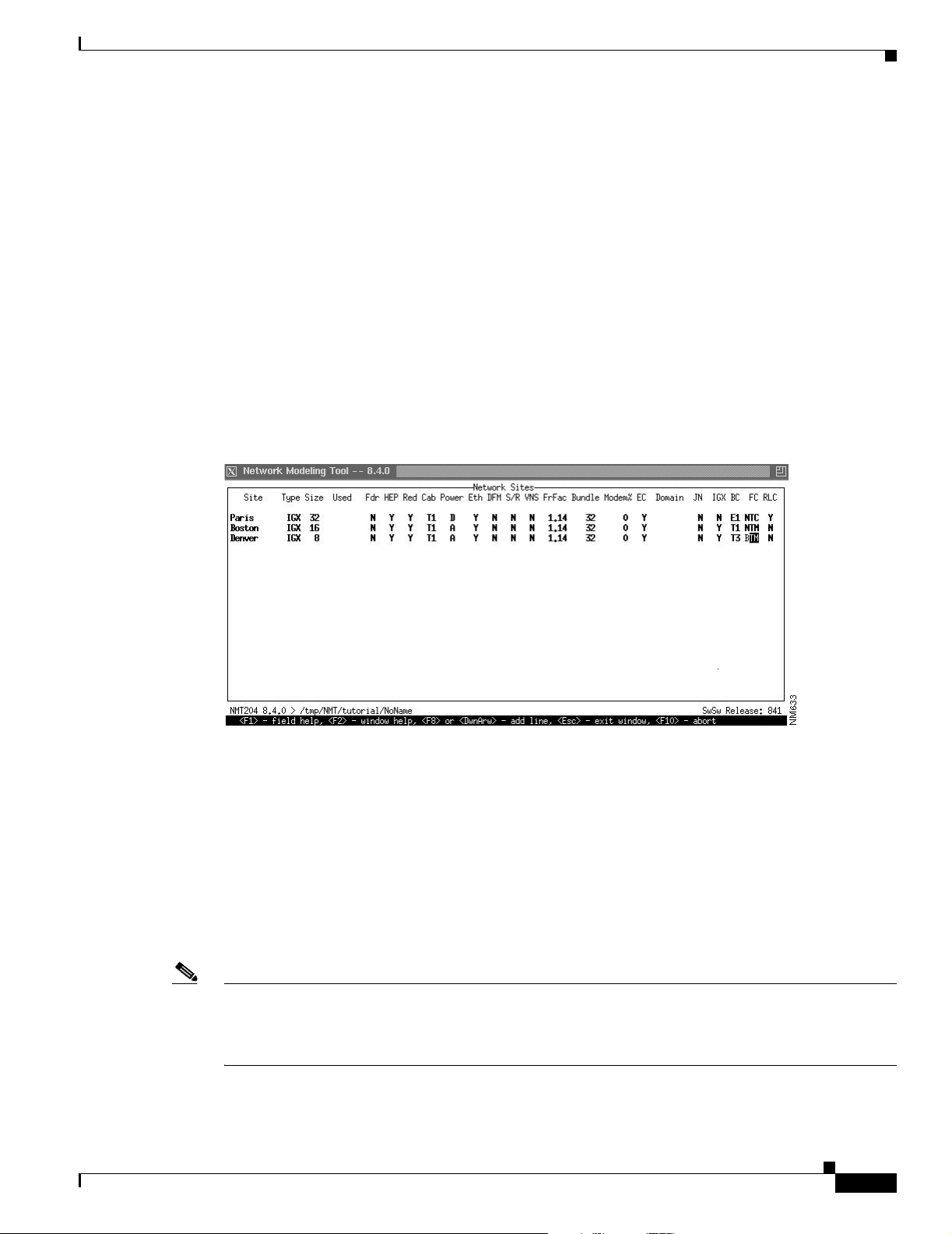
automatically generate implicit network elements. Figure 3-4 shows an example of a configuration table.
Figure 3-4 Sites Table
Note The NMT assumes that the version of the switch software you are using is the same as that of the NMT
OL-10426-01, Rev. A0
You can either input or import a configuration.
• To input a configuration, you enter data into tables accessed from the Configure menu. For
information about inputting a configuration, refer to the section “Keyboard Commands” earlier in
this chapter, and see the chapter “Modeling Simple Networks,” which provides a step-by-step
example of inputting a configuration.
• To import data from Cisco Wan Manager (CWM), see the chapter “Configuration Extraction Tool”;
to import (or export) WANDL files, see the chapter “Third-Party Interface”; to import (or export)
Microsoft Excel files, see the chapter “SpreadSheet Interface.”
For descriptions of the fields contained in the Configure menu selections, refer to Chapter 4,
“Configuration Tables and Fields.”
software. If that is not the case, select Model Settings from the Configure menu and specify the switch
software version you are using by entering a release number next to Network Parameter Switch Software
Release. Individual platforms can have unique switch software releases specified in the Site table.
Cisco WAN Modeling Tools Guide
3-5
Page 38

File Menu
Utilities
Chapter 3 Using the NMT
Use the Utilities in the Config menu to make bulk changes to the CNF file.
• Expand Quantities — For all records for quantity field value of greater than one, change the quantity
value to one and duplicate the record the number of times that appeared in the quantity field.
• Table Conn Merge — Merges connections with identical parameters into one table record,
increasing the quantity field. An additional feature enables you to set the options to average the
traffic values to further reduce the table record count.
• Order Table Data — Options for sorting the CNF tables by site name.
• Rename or Merge Site — Modify site names.
• Group Rename or Merge— Modify group names.
• Adjust %Util— Modify the %util fields in the connection tables.
• Mesh Data — Add new records such that link or connection tables are fully meshed. Options
determine how the mesh is to be done. The weight field in the site table can be used in several ways
to affect the outcome of the mesh.
• VH Coordinates — Utilities to create VH coordinates for the map display.
Edit Options
• Path Expansion— Update paths with complete slot/port information.
• Diff Pref Route vs. Cur— Compare all preferred routes to the existing routes in the CNF file.
• Clear Data — Reset or blank out various fields in the CNF file.
• Upgrade Implicit — After running ROUTE or EXECUTE command, have NMT insert any multiple
switches at one site as separate entries into the site table
• Feeder MGX8220’s — After running ROUTE or EXECUTE command, have NMT insert any
implicit MGX8220’s at one site as separate entries into the site table
• Store Model Data — After running ROUTE or EXECUTE command, have NMT store various data
back into the CNF file. Individual fields can be selected in an additional menu.
Edit Options invokes edit form that includes few flags that control UI in the edit tables
• Strict UI Checking — controls validation of some of the fields like link type, link front card,
connection interface, etc. Note, that all the data will be checked in any cases during Execute
operation.
• Default CNF file — defines the name of CNF file that is used as a templates for edit tables. The first
entry for each table in this file is used as default values when adding new table entries.
• Correct Table Data — controls writing back corrections that makes NMT back to the user data.
If set to ‘Y’ (default value), the NMT will write back to the CNF all the corrections it makes
internally; if set to ‘N’ - user data will remain in the state the user sees them in the edit tables.
3-6
• Check Route Paths — Enables/disables route checking.
• Suppress Duplicate Messages — After five similar messages appear in the log, suppress all
additional messages of that type, and provide the count of suppressed messages.
If set to ‘N’ (default value), the UI will skip route checking, so it will be checked during Execute
operation. If set to ‘Y’ the user will be able to check routes in the UI and correct them if necessary.
Cisco WAN Modeling Tools Guide
OL-10426-01, Rev. A0
Page 39

Chapter 3 Using the NMT
Defaults
Note This option does not apply to the site names field in any table.
Execute Menu
Display Menu
To create your own defaults for any or all tables, create a CNF file and call it DEFAULTS. Save it to your
working directory. Any new records you create for a field in any table will have the values of the first
entry in that table. To use an existing file for your defaults, select it in the edit options window.
You can access the following commands from the File menu in the Network Design Tools window:
• Route—Routes traffic over specified links
• Fail Analysis...—Performs failure analysis on the lines and forces NMT to create alternate routes.
• Build Sites—Provisions the nodes without routing.
• Optimize—Uses selected links to create a least cost topology.
Display Menu
You can access the following commands from the File menu in the Network Design Tools window:
Sites Displays customer site information.
Links Displays a list of links in the current network.
Network Summary Displays summaries of the current network costs and routing status.
Total Links Load Displays static load estimates by traffic type for each link in the network.
ATM & F r Po r ts Site name, connection type (for example, FRM-V35), slot number, port number,
Data & Voice Ports Site name, connection type (for example, SDP-V35), slot number, port number,
Connection Routes Connection to/from, number of connections, connection type (for example, FR,
Failed Connections Displays failed connections and connections that have not been routed.
Parts List Listed by site, including part number, description, quantity, cost per site.
Resources Graphical display of each node’s card cage showing front cards and back cards.
PNNI Topology Displays PNNI logical links.
User Message View or clear the message log. You can also view the message log by entering
Map Network topology map.
port speed (cells or packets per second), SUM MIN (port load).
port speed.
56), path number of hops, delay time in msec for voice and NTS connections.
<Ctrl> W.
OL-10426-01, Rev. A0
Cisco WAN Modeling Tools Guide
3-7
Page 40

Display Menu
Report Menu
Chapter 3 Using the NMT
Use the Report menu to define, generate, display, and save reports. The menu contains the following
options:
Define Selects which tables to include in a report. Figure 2-5 shows the Define Report
window. In this window you can specify the contents of the report and also add
a report header. Enter one of the following options:
Y—includes a report in a report file.
N—do not include a report in the report file.
X—do not generate a report (saves execution time).
Generate Names and generates a report.
View Selects a report to display.
Erase Deletes a report from the current directory.
Path Sets the directory path.
Set Options Specifies the following report variables:
• Price Option— Enter 0 for normal pricing. Enter a number from 1 through 5
to specify number of years in lease.
• Detail Reports— Enter Y to generate Bursty Link Load Reports. Enter N to
exclude Bursty Link Load Reports.
• Output DBF Reports— Enter Y to create a report in DBF and text format.
Enter N to create report only in text format.
• Output Pref Rte — Sets Preferred routes. Y to output a file of preferred
routes that can be inserted into switch CLI commands to create those routes.
• Bundle Connections — Y will keep connections bundled by routing
properties in the reports to reduce the size. N will expand reports for each
individual connection.
• Output Map Info —Y will write the information from a NMT command to
be input into the MAP graphical display. N will not to reduce execution time.
• Map Site Feeders — Y will display all feeder sites and their links on the map,
N will display only routing nodes and links.
• Map MultiNode Sites — Y will display each switch in the case where NMT
generated addition switches at a site, N will display only one marker for site
table entry.
3-8
Cisco WAN Modeling Tools Guide
OL-10426-01, Rev. A0
Page 41

Chapter 3 Using the NMT
Figure 3-5 Report Options
Maintenance Menu
Keyboard Commands
Help Menu
Quit
Use the Maintenance menu to revise product costs, add optional equipment (for reference purposes),
and provide information about line costs. This menu also allows you to read, write, erase, and set the
path for maintenance files. The menu contains the following options:
Parts List Displays a list of Cisco Systems WAN part model numbers.
Line Cost Displays line cost information.
Read Loads a previously saved maintenance file.
Write Saves a maintenance file.
Erase Deletes a maintenance file.
Change Path Changes the current directory path.
The NMT has several kinds of online help. The Help menu provides information about how to use the
program and describes many of the menus and menu items in the NMT.
The Quit item on the NMT Menu Bar is used to close the NMT application. When you choose this option,
a popup window appears asking whether you are sure you want to quit NMT. Type Y and hit return to
quit. Type No and hit return to continue working in NMT.
Keyboard Commands
To select a top-level menu item in the NMT design window, use the left and right arrow keys. Press Enter
to access a submenu. Select submenu entries with the up or down arrow key or by typing the first letter
of the submenu entry. To exit from a table or menu, press Escape.
OL-10426-01, Rev. A0
Cisco WAN Modeling Tools Guide
3-9
Page 42

Keyboard Commands
Chapter 3 Using the NMT
The NMT has many keyboard commands to help you create and revise configuration tables and reports.
Table 3- 1 lists the Sun workstation key assignments used for editing data in the NMT.
Table 3-1 Sun Key Assignments
Key Function Description
F1 Field help Text description of the current field.
F2 Window help Displays a list of key definitions for data entry and editing.
F3 Copy line Copies the current line. The Repeat Line command then
can be used to repeat it one or more times.
F4 Repeat line Inserts a previously copied line below the current line.
F5 Choice List Displays a list of key definitions for data entry and editing
(same as F2).
Note This command is only available on the PC version
of NMT.
F6 Clear end-of-field Clears one field in a table.
F7 Delete line Removes the current line. The line deleted will be saved in
a buffer from which it can be recalled by using the
Undelete command.
F8 Insert line Inserts a table entry below cursor.
F9 Undelete line Inserts the last deleted line above the current line. If the
command is repeated, the last deleted line that has not been
undeleted (if any) will be inserted above the current line. A
maximum of 50 lines can be undeleted.
F10 Cancel/Abort Table Exits a table without checking data. If the Exit command
has been previously issued, the command will delete all
lines in the table that contain illegal data.
Up Arrow Previous line
Down Arrow Next line/Add row Inserts default field values for new rows.
Left Arrow Previous Field
Right Arrow Next Field
Page Up Previous Page
Page Down Next Page
Home First Page, first row
End Last page, last line
Help, F12 Choices Lists choices for the selected field. Lists of choices are
available for most fields that accept three or more
non-numeric values.
3-10
In the site field, you choose a site by pressing Help (or F12)
and then using the up or down arrows to scroll through the
site names; press enter to select a site.
Esc Exit Exits a table or menu and, in some cases, checks the data in
the table.
Ctrl-f Find Site Prompts you for site name, and then finds the next table
entry using that site name.
Cisco WAN Modeling Tools Guide
OL-10426-01, Rev. A0
Page 43

Chapter 3 Using the NMT
Help Keys
Modeling Processes
Table 3-1 Sun Key Assignments (continued)
Key Function Description
Ctrl-g Go to line/Display
line
Ctrl-h First Field Moves cursor to the first field in the row.
Ctrl-j Last Field Moves cursor to the last field in the line.
Ctrl-k Left One Space Moves cursor left one character (within a selected field). If
Ctrl-l Right One Space Moves cursor right one character (within a selected field).
You can get help using keyboard commands as follows:
Reports line number of current table entry. Entering a
number allows you to go to that specific table entry.
the cursor is on the first character in the field, this
command moves the cursor to the previous field.
If the cursor is on the last character in the field, this
command moves the cursor to the next field.
• Pressing the F1 key. If you are unsure what data to enter when the cursor is in a field of a table, you
can press the F1 key to display a help screen that lists and describes the options for that field.
• Pressing the F2 key. This provides a description of the window editing and cursor capabilities of the
function keys for a selected table.
• Highlighting an item in a menu, which displays a one-line description.
• If you enter an unacceptable value (for example, IXG instead of IGX) into an NMT field, the system
beeps and an explanation is displayed at the bottom of the window.
• Press the Help or F12 key (or F5 in the PC version of NMT) to display a “Choice List”. You can
scroll through the list to select a valid entry for the field. Not all fields have a choice list.
Message Keys
Enter Ctrl-w from any where in NMT to view working and error messages from your working session.
Modeling Processes
The NMT models your configuration when you select one of the options under the Execute menu.
If there is any problem with your configuration, a message box displays the following message:
New warning messages generated.
OL-10426-01, Rev. A0
To check your warning messages, enter Ctrl-w.
Cisco WAN Modeling Tools Guide
3-11
Page 44

Error Checking
Chapter 3 Using the NMT
The NMT generates three types of messages:
• L—Log messages are generally displayed when the NMT records the command the user requested.
• I—Informational messages generally indicate that site or link parameters have been modified to
comply with user entered data.
• W—Warning messages are generally displayed when the NMT modifies connection data.
• E—Error messages are generally displayed when the NMT cannot create a topology because of
incorrect data.
The message box also keeps a log of the commands executed. The message box always scrolls to the last
viewed message.
An example of warning output is shown in Figure 3-6.
Figure 3-6 Example of NMT Warning Output
Error Checking
The NMT does automatic error checking in the following circumstances:
• When you exit a data entry screen, the NMT automatically performs a line-by-line check of the data
in your table.
• When you exit the Configure menu, the NMT checks your data again and, in many cases, makes
corrections. If the NMT makes any changes or finds any errors, it generates information, warning,
or error messages as needed. When this happens, you are instructed to select Warnings & Errors
from the Display menu.
Note If you are working with a large configuration, you may want to exit the data entry screen without
• When you select Route, Optimize, or Build Sites from the Execute menu, the NMT checks your
data and may make corrections. If the NMT makes any changes or finds any errors, it generates
information, warning, or error messages as needed. When this happens, you are instructed to select
Warnings & Errors from the Display menu.
To thoroughly check and correct all configuration tables in VI mode, select Table Scan from the
Configure menu.
having the NMT perform a line-by-line check. To do this, press the F10 key instead of Escape
key.
3-12
Cisco WAN Modeling Tools Guide
OL-10426-01, Rev. A0
Page 45

Chapter 3 Using the NMT
Troubleshooting NMT
The table below describes a common NMT problems and what can be done about it.
Troubleshooting NMT
Symptom
Probable Causes
Solution
Your mouse does not work on the PC version of NMT.
Note The mouse is not supported in the UNIX version of NMT.
The Quick Edit Mode option is checked in the Console window’s
Properties<Options menu.
Open the Properties menu and ensure that Quick Edit Mode is not
checked in the Options tab. If it is checked, click on the box next to
Quick Edit Mode to un-check it, and then click OK.
OL-10426-01, Rev. A0
Cisco WAN Modeling Tools Guide
3-13
Page 46

Troubleshooting NMT
Chapter 3 Using the NMT
3-14
Cisco WAN Modeling Tools Guide
OL-10426-01, Rev. A0
Page 47

Configuration Tables and Fields
This chapter describes the fields in the tables accessed through the Configure menu.These tables
describe sites, links, traffic types, and more. This data can be created and edited with the NMT, or
imported into the tables from other systems.
Network topologies are defined by sets of tables. Each table entry defines a network element, and each
table field defines a specific characteristic of that element.
The Site table, which defines the switch locations, is the only mandatory table. In the other tables, you
usually only need to define the site name field in the other tables. You can use the NMT default values
in almost all cases to get familiar with the modeling process.
There is no order requirements in these tables. Use the CONFIG/UTILITY to sort the table entries
automatically.
General Table Information
CHAPTER
4
The following legend refers to the Notes column in the tables that follow. Refer to this legend when
deciding whether to edit an NMT default value.
• M—Mandatory. If you are revising this table, you must revise this field.
• E—Evaluate. If you are revising this table, you should consider revising this field. For instance, this
field may require modification if you are working with a tiered network, an ISP, a network that
requires highly regulated bandwidth, or one in which cost factors must be highly regulated.
• O—Optional. If you are revising this table, you need not revise this field. Defaults are generally
suitable.
• P—Parts. Required for generating an accurate parts list.
• H—Help. Press F12 or the Help key to call up a list of choices.
• X—Entries generated by the NMT that cannot be edited.
The DBF column lists the DBF field name, and any additional translation information. There are also
columns for the CET (CWM) and TPI (WANDL) translations.
An asterisk in the Configuration Extraction Tool (CET) column or the Third Party Interface (TPI)
column indicates that the CET and/or the TPI supports a particular field. For instance, the CET extracts
site names from the Cisco Wan Manager (CWM) database, so there is an asterisk in the site row of the
CET column in Ta bl e 4- 1. The asterisk indicates that the field is translated as described in the legend
above. If the translation is more complex, it is described in the CET or TPI column.
OL-10426-01, Rev. A0
Cisco WAN Modeling Tools Guide
4-1
Page 48

Sites Table
Sites Table
Chapter 4 Configuration Tables and Fields
The sites table contains information about all sites in your network. All other tables using the sites field
rely on the information in this table. To display the sites table, select Site from the Configure menu. The
two most important fields of the site table are the site name and the node type field. The site name field
defines the label string of the site, and must be valid and unique. The node type field defines what kind
of switch is at this location.
Use the NMT Site Table to explicitly specify all feeder equipment in the MGX, BPX, and IPX products.
You can also provision feeders and additional routing IGX shelves as required by the connection
demand.
Figure 4-1 NMT Network Sites Table
The primary CWM data source for the site table is the node table. The primary WANDL data source and
target for the site table is the MUXLOC file.The Site Table fields are described in Ta bl e 4- 1
Ta b l e 4 - 1 .S i t e Tab l e
Field Defaults Notes Description and Comments DBF CET TPI
Site – M/H Site name (up to 10 characters).
Names are case sensitive. Keep
the names short and easy to
remember. This field must be
revised before you revise any
other fields or tables.
Node Type IGX M/H Type of product (IGX, BPX,
MGX, IPX).
Type Used – X Protected field that shows the
size of the node after the NMT
builds a network.
NAME *
Reduced to unique
10 char name if
longer than 10
chars.
TYPE *
Limitations: IGX
not recognized
until Release 8.2.
n/a
Translated to both
Short name and Long
name*
nodeparam file
4-2
Cisco WAN Modeling Tools Guide
OL-10426-01, Rev. A0
Page 49

Chapter 4 Configuration Tables and Fields
Table 4-1 .Site Table (continued)
Field Defaults Notes Description and Comments DBF CET TPI
Site Type Switch M/H Function of platform at the site.
Can be a switch, feeder,
STYPE * Restrictions imposed
on links
controller or a stand alone unit.
SwRel O Software release of the
SW_REL *
switch(es) at this site. If blank,
this field defaults to the global
value defined in the Model
Settings.
PC Blank P Processor card. If Blank, use the
latest.
NPC *
From card table.
Default value used
until Release 9.1.
Red Y P Redundancy. Y—site has
RED
redundant components. N—site
does not have redundant
components.
Cab T1 P Cabinet. Specifies cabinet type
CABINET
(T1—American or Far Eastern;
E1—European).
Power A P/H Power supply. AC_DC
DFM N O Data Frame Multiplexing.
DFM
Y—site uses DFM. N—site does
not use DFM. If a data
connection terminating at this
site has a DFM setting of Y, it
takes precedence over the site
setting.
S/R P O Save/Restore. Y—site uses
S_R
save/restore configuration
software. N—site does not use
save/restore configuration
software.
FrFac 1.14 O Frame Relay Factor. Multiplier to
FR_FAC
account for frame overhead on
the IPX Mux Bus. (The 1.14
default is an IPX legacy setting.)
Bundle 24 O Maximum number of
BUNDLE
connections that can be routed
simultaneously. Default is 32;
choose between 1 and 29.
Modem% 0 E Percentage of modem traffic on
voice connections originating at
MODEM_P
CT
this site.
Sites Table
OL-10426-01, Rev. A0
Cisco WAN Modeling Tools Guide
4-3
Page 50

Chapter 4 Configuration Tables and Fields
Sites Table
Table 4-1 .Site Table (continued)
Field Defaults Notes Description and Comments DBF CET TPI
IGX Y E Type of feeder node. Y—feeder
IGX
nodes should be IGX. N—feeder
nodes should be IPX.
This field applies only if NMT
needs to add a feeder node.
TF N E Tiered Feeder Flag.
N- for router.
Y- for feeder;
TF
This field applies only to added
feeder nodes.
BC T1 E/H Back card. Feeder link back card.
BC
This field applies only to added
feeder nodes.
FC NTM E/H Front card. Feeder link front
FC
card.
This field applies only to added
feeder nodes.
RLC N E Redundant link card. Specifies
whether link is redundant.
This field applies only to added
feeder nodes.
NPA NPA of the site location. Not
used in NMT but carried for
reference and used in WANDL.
NXX NXX of the site location. Not
used in NMT but carried for
reference and used in WANDL.
LON Longitude of site location. Not
used in NMT but carried for
reference and used in WANDL.
Several different formats are
available in the string field.
LAT Latitude of site location. Not
used in NMT but carried for
reference and used in WANDL.
Several different formats are
available in the string field.
RA H 0 Routing algorithm version of
Autoroute. Use 'H' for minimum
hops, 'C' for Least Cost, and 'CD'
for least cost with delays.
PNNI Blank 0 Y/N flag indicating whether the
node is capable of PNNI routing
or not.
RDL
NPA *
NXX *
LON F: muxloc
LAT F: muxloc
RM
PNNI *
4-4
Cisco WAN Modeling Tools Guide
OL-10426-01, Rev. A0
Page 51

Chapter 4 Configuration Tables and Fields
Table 4-1 .Site Table (continued)
Field Defaults Notes Description and Comments DBF CET TPI
PNNI_PG N 0 name of the PNNI group, as
PNNI_PG
defined in the PNNI Domains
table. If the name in this table is
not in the PNNI Domain table,
then it is just represents a logical
grouping that the user can define
any way they wish.
PGL_PR 0 0 The Peer Group Leader Election
PGL_PRI * *
Priority is a numeric value
determining which site will be
the peer group leader. The
highest value in the peer group
will be the leader.
Xrstr N 0 Y/N flag for transit restriction. If
XR
Y, the PNNI node cannot be used
for transit calls (via connections).
MAPV Map vertical coordinate. Can be
loaded and unloaded from the
NMT map process.
VER *
Only available if
CWM or SV+ map
has been
configured.
*
If no NMT
longitude/latitude
fields, use this to
create latitude in
table muxloc
Sites Table
MAPH Map horizontal coordinate. Can
be loaded and unloaded from the
NMT map process.
CT Blank 0 Country code. A two digit
country code carried but not used
by NMT. Used in WANDL for
tariff lookups.
Weight 0 0 User defined weight that can be
used for generating links and/or
connections using the MESH
commands in the
CONFIG/UTILITIES menu.
Network 0 The network domain name this
site is assigned to.
Also written to
graphcoord file.
HOR *
Only available if
CWM or SV+ map
has been
configured.
*
If no NMT
longitude/latitude
fields, use this to
create longitude in
table muxloc
Also written to
graphcoord file.
CT *
WEIGHT nodeweight file
NET_NAME *
DOMAIN in the
muxloc file.
OL-10426-01, Rev. A0
Cisco WAN Modeling Tools Guide
4-5
Page 52

Links Table
Configuring Sites Example
This section provides an example for configuring Sites.
Step 1 Enter the information shown in Table 4- 2 into the Sites table.
Table 4-2 Field Changes for the Sites Table
Chapter 4 Configuration Tables and Fields
BC (Back
Site Type Power IGX
Paris IGX D N E1 NTC Y
Boston IGX A Y T1 NTM N
Denver IGX A Y T3 BTM N
Note Except where noted in this table, each node uses default values.
Step 2 Use the left and right arrows to highlight Configure and press Enter.
Step 3 Select Sites and press Enter. A new sites table is displayed.
Note Select a menu choice by using the up and down arrow keys, or by typing the first letter of the
Card)
FC (Front
Card)
RLC (Redundant
Link Card)
item selected.
Step 4 Highlight the Site field by pressing the Down arrow. Type Paris. You have now created a site.
Step 5 To modify the NMT default site values, cursor or tab to each of the fields listed in Tab le 4 -2, and enter
the data that applies to the Paris site. There are two ways to enter data:
1. Press the Help key to see a list of choices. Lists of choices are available for most fields that accept
three or more non-numeric values. Make a selection using the cursor and press Enter.
2. Type directly into the field. Press the Delete key if you make a mistake.
Step 6 Press the down arrow to insert a new line in the table.
Step 7 Repeat Step 4 and Step 5 for Boston, and Step 4 and Step 5 for Denver. The Sites table should look like
Step 8 Press Escape to accept the entries and return to the Configure menu.
Links Table
Cisco WAN Modeling Tools Guide
4-6
the one shown in Figure 4-1.
The Links Table contains topological and cost information about every existing link or possible link
candidate in the network.
OL-10426-01, Rev. A0
Page 53

Chapter 4 Configuration Tables and Fields
Minimal Link Table Usage
For existing links, the Keep field should be set to the number of existing links, with the characteristics
described in the record. The Links command displays existing links and possible links considered for
the network design. The key fields in the link table are the site ends, the trunk type, and the keep field.
The primary CWM data source for the Links table is the link table. The WANDL translation for the link table
is the bblink file. When translating from NMT to WANDL, a fixlink file identical to the bblink file is created.
The Link Table fields are described in Tabl e 4 -3.
Table 4-3 Link Table
Field Defaults Notes Description and Comments DBF CET TPI
Site 1 – M/H Name of site at one end of the link
using a name from Sites table.
Port ID 1 0 E Logical slot/port number at Site 1 for
the connection. Enter 0 and NMT
assigns. Enter n.m to specify port.slot.
Site 2 – M/H Name of site at other end of the link
using a name from Sites table.
Port ID 2 0 E Logical slot/port number at Site 2 for
the connection. Enter 0 and NMT
assigns. Enter n.m to specify port.slot.
M Z O/H Media. Media type of trunk.
IF1 T3 O/H Trunk type and capacity. The Trunk
type is the interface used on the trunk
and defines the backcard. An optional
line size can be prepended.
IF2 blank O/H IF2 trunk type is used only if different
from the first, in the case of virtual
trunks.
DS0 0 O/H DS0 field is the number of sub-units
for a DS1 line. 4 through 24 are valid
for T1, and 4 through 30 are valid for
E1.
If the trunk is not a DS1 type, this field
is ignored.
Trnk_Cd O/P/H Trunk card. The front cards for this
link.
SITE1
HUBID1
SITE2
HUBID2
M
TRUNK
TRUNK2
TRNK_CAP
TRNK_CAR
D1/
TRNK_CAR
D2
**
**
**
**
*
*
*
Y1 trunks shown
as T1, and T2
trunks shown as
T3. Until
Release 9.1,
broadband
trunks were
determined
heuristically,
based on port
speed and card
type.
**
**
*/*
Links Table
OL-10426-01, Rev. A0
Cisco WAN Modeling Tools Guide
4-7
Page 54

Chapter 4 Configuration Tables and Fields
Links Table
Table 4-3 Link Table (continued)
Field Defaults Notes Description and Comments DBF CET TPI
Keep 1 E Number of existing links. If the Keep
field is 0, the link will be ignored in the
route command and considered for the
optimize commands.
KEEP
*
Since slot, port
are included, this
field is always
*
set to 1.
Used 0 X Shows the size of the node after the
n/a
NMT builds a network using the
optimize command.
Reserve 600/600 O Trunk reserve. Estimate of the
overhead on each link needed for
collecting network statistics and other
administrative overhead. The reserve
size is subtracted from the total link
capacity prior to calculating routes.
RESERVE1 /
RESERVE2
*/*
Defaults applied
to links between
BPX switches
and tiered
network feeders.
*/*
The units of statistical reserve can be in
ATM cells (CPs) or Fastpackets (pps).
Rcv_Rate 0/0 O Receive rate. Largest number of pps or
cps that the node at site 1 can receive
over a link from site 2. The second
BB_MAX1 /
BB_MAX2
*/* */*
field is the largest number of pps or cps
that the node at site 2 can receive over
a link from site 1. Only used for
broadband links (T3/E3) at IGX/IPX
sites, or BXM links. The units are pps
or cps respectively.
If you enter 0 here, the default, NMT
will set this field to the highest value
possible for the card. Rcv_Rate
supported on the AIT, ALM, BTM,
and BXM card.
Red N P Redundancy. Specifies whether site has
RED
redundant components. Y—site has
redundant components. N—sites does
not have redundant components.
VT_Rate&
Typ e
0 O Virtual Trunk Rate. Bandwidth of the
trunk in cells per second. (VTs must
VT_RATE
**
have VT in media field.)
Traffic Blank 0 Types of traffic allowed on this link. If
TRAFFIC
blank, all types are allowed.
LRd N O Link redundancy. Y—spare trunk is
BACKUP
used on redundant link (for BPX to
IBX/IPX links only). N—spare trunk is
not used on redundant link.
Dist 0 E Distance between sites in miles or
DIST
kilometers. Must be consistent with the
Line Cost table in the Maintenance
menu.
4-8
Cisco WAN Modeling Tools Guide
OL-10426-01, Rev. A0
Page 55

Chapter 4 Configuration Tables and Fields
Table 4-3 Link Table (continued)
Field Defaults Notes Description and Comments DBF CET TPI
$/Mo 0 E Cost per month of trunk from Site 1 to
COST_MO
Site 2. If blank, NMT calculates cost
using the Dist field and the data in the
Line Cost Table (in the Maintenance
menu). If you enter a value here, use
zero in the Distance field.
Instl 0 O Installation cost of a trunk.
Fdr1ID 0 E Feeder 1 ID. Part ID for the IMATM
INSTALL
FDR1ID
trunk on an MGX 8220 edge
concentrator.
Fdr2ID 0 E Feeder 2 ID. Part ID for the IMATM
FDR2ID
trunk on an MGX 8220 edge
concentrator.
IMA_RD 0 O IMATM resiliency degree. Number of
IMA_RES
T1/E1 lines of AIMUX port that are
allowed to fail before the AIMATM
trunk goes down.
NTS_Q 0/0 O Queue Depth in Transmit/Receive
direction for Non Time Stamped
connection loads. When the entry is 0,
NTS_QDS/
NTD_QDR
NMT will assume the default queue
depth.
Voice_Q 0/0 O Queue Depth in Transmit/Receive
direction for Voice connection loads.
When the entry is 0, NMT will assume
DSI_QDS/
DSI_QDR
the default queue depth.
Cost 10 O The Least Cost Routing (LCR) weight.
AR Y O Y/N flag indicating if the link is
WT
AR
*
Autoroute enabled.
PNNI N O Y/N flag indicating if the link is PNNI
enabled.
PNNI
Heuristic used
for BPX nodes
Links Table
AggToken 0 O The value used in the PNNI link
aggregation algorithm. At least one
link with a unique aggregation token
will always be known in the PNNI
logical topology.
Comment 0 Comment field used in NMT only.
OL-10426-01, Rev. A0
AGG_TOK
COMMENT
Cisco WAN Modeling Tools Guide
4-9
Page 56

Chapter 4 Configuration Tables and Fields
Link Special Cases
Table 4-3 Link Table (continued)
Field Defaults Notes Description and Comments DBF CET TPI
AW 5040 O Administrative weight used for least
cost in the PNNI routing algorithm.
Comment A free field comment field. Translates
to the WANDL link label field if
present.
AW
COMMENT
Not available
until sv+ Release
9.0.
The comment
field is used as the
link label in the
bblink file. If this
field is blank, a
link label will be
generated only if
it is required to
uniquely
determine the link
in WANDL.
Link Special Cases
IMATM Trunks
This section describes link table configuration for the following special cases:
• ATM Trunks
• Virtual Trunks
An IMATM trunk is an ATM link of one to eight DS1 lines. Each IMATM trunk card uses a slot of an
AXIS shelf, and is connected to the BPX switch by means of a T3/E3 port on a BNI card. The trunk can
be configured so it fails only if more than n DS1 lines fail. The NMT does not model IMATM trunk
resiliency during failure analysis.
Table 4-4 IMATM Trunk Configuration
Topic Required Settings Comments
Specifying an IMATM Trunk Links table
Trunk (type) field: Specify a trunk of
T1 or E1. Prepend the number of
DS1s for the trunk, for example 5:T1
or 8:E1.
Trunk (capacity) field: For E1 links,
specify number of DS0 in the line: 30
for CCS signalling or 32 for Clear
Channel signalling.
Trunk card field: Specify IMA for
both trunk front cards.
IMA_RD field: enter the resiliency
degree.
Both sites must be BPX.
The IMA_RD field is on the
second screen of the Links table.
4-10
Cisco WAN Modeling Tools Guide
OL-10426-01, Rev. A0
Page 57

Chapter 4 Configuration Tables and Fields
Virtual Trunks
The virtual trunking feature introduces the concept of defining multiple trunks within a single trunk port
interface. It was developed to provide connectivity for a hybrid network consisting of Cisco ATM
switches through a public ATM cloud.
NMT models virtual trunks on BNI, BXM, BTM, and AIT ports. Refer to Tabl e 4 -5 for information on
virtual trunk configurations.
Table 4-5 Virtual Trunk Configuration
Topic Required Settings Comments
Specifying a Virtual Trunk Links Tab le
M (Media) field: Enter VT
Trnk_Cd field: Both ends must be
specified. The ends can be different.
VTRate field: Specify the VT rate in
cells per second.
...&Type field: Define the ATM type
of link (ABR, CBR, UBR, VBR, or
leave blank if the links support all
types of traffic).
Voice Table
If the back cards are different, the
maximum size of VT is the
minimum of the two protocols.
Voice Table
The Voice Table contains topological information about IGX voice connections in the network. The
important fields in the voice table are the site ends, the type, and the BackCard field. The type defines
the voice compression protocol, and the backcard defines the connection type at the customer's premise.
The primary CWM source of the voice table is the USER_CONN table. The WANDL file for translation is
the demand file. The Voice Table fields are described in Ta b le 4- 6 .
Table 4-6 Voice Table
Field Defaults Notes Description and Comments DBF CET TPI
Site 1 – M/H Site name of owner of a
connection.
Port ID 1 0 O Logical slot/port number at Site
1 for the connection. Enter 0
and NMT assigns. Enter n.m to
specify port.slot.
Site 2 – M/H Site name of remote end of a
connection.
Port ID 2 0 O Logical slot/port number at Site
2 for the connection. Enter 0
and NMT assigns. Enter n.m to
specify port.slot.
SITE1 * *
ID1 *
SITE2 * *
ID2 *
OL-10426-01, Rev. A0
Cisco WAN Modeling Tools Guide
4-11
Page 58

Chapter 4 Configuration Tables and Fields
Voice Table
Table 4-6 Voice Table (continued)
Field Defaults Notes Description and Comments DBF CET TPI
Qty 1 M Quantity. Number of
connections of the specified
type.
CONNS *
*
Since slot and port are
included, this field is
always set to 1.
Type C32 M/H Type of voice connection.
E2E_TYPE SPVC M The end to end type of the
connection. PVC, SPVC,
XPVC, Hybred and 1Ended are
all valid.
Sig CAS O Signalling type: channel
associated signalling (CAS), or
common channel signalling
(CCS), or clear (CLR).
PR 0 O Rerouting priority—0 to 15,
with 0 the highest rerouting
priority.
Ad – O/H Restriction type. Ad is short for
Avoid. Specify the media types
that should be avoided when
the connection is routed.
Red N P Redundancy. Specifies whether
connections are going to be
redundant. Applies to CDP
redundancy.
%Util 40/40 E Trunk utilization, based on
minimum information rate
(MIR) percentage. (Default is
40% because studies have
shown that during
conversations, one end of the
line is unused 60% of the time.)
TYPE *
E2E
Coded:
C - PVC
S- SPVC
H- Hybred
X - XPVC
E - Single ended
SIG
COS
AV D
RED
PCT_UTIL1 /
PCT_UTIL2
Derived heuristically
prior to Release 8.5. T
connections shown as
P; FastPAD CELP8
and CELP48 conns
shown as ATC16.
Defaults used prior to
Release 8.5.
Defaults used prior to
Release 8.5 and for
FastPAD. The data
may be unreliable if it
changed after adding a
connection.
*
*
*/*
4-12
Cisco WAN Modeling Tools Guide
OL-10426-01, Rev. A0
Page 59

Chapter 4 Configuration Tables and Fields
Voice Table
Table 4-6 Voice Table (continued)
Field Defaults Notes Description and Comments DBF CET TPI
BC T1/T1 E/H Back card type (CDP Set). Use
workstation Help or F12 key
for choice list.
BC1 /
BC2
*/*
Until Release 9.1, field
was determined
heuristically, based on
the observed ports
used.
Fdr1ID 0 E Feeder 1 ID. Logical port
number for the connection at a
3810 or FastPAD feeder at the
local site (not used).
Fdr2ID 0 E Feeder 2 ID. Logical port
number for the connection at a
3810 or FastPAD feeder at the
remote site (not used).
FdrBc / O/H Feeder back card voice card
type.
Index 0 O SNMP Connection Index for
CWM reference for this
connection.
Rt_Metrics AW M How the connection is routed.
Cost 0 O Maximum cost allowed for the
least cost routing path for this
connection.
DR N O Direct routing. Indicates that
the connection must use the
preferred route provided. If it
cannot use the preferred route,
the connection should not be
routed.
Preferred_
Route
O The preferred route of the
connection. The first and last
routing site are optional and all
feeder sites are optional. An
equal sign separates the site
names. Specific links are
specified by the slot.port for the
incoming and/or outgoing port.
FDR_ID *
FDR_ID2 *
FDR_INT1 /
FDR_INT2
SNMP_INDEX *
RT_ MET
MAX_COST
DR
Route is stored in
19 fields:
PR_SITE2,
PR_SITE3,
PR_SITE4,
...
PR_SITE20
MC 3810 feeders are
not supported.
MC 3810 feeders are
not supported.
*/*
*
Available starting with
Release 7.2. Specific
Trunk not available
until Release 8.4.
Routes are not
available on PNNI
networks.
*
OL-10426-01, Rev. A0
Cisco WAN Modeling Tools Guide
4-13
Page 60

Chapter 4 Configuration Tables and Fields
Data Table
Table 4-6 Voice Table (continued)
Field Defaults Notes Description and Comments DBF CET TPI
Current_Ro
ute
O The current route, from CET
extractions.
Route is stored in
19 fields:
CR_SITE2,
CR_SITE3,
CR_SITE4,
...
*
Available starting with
Release 7.2. Specific
Trunk not available
until Release 8.4.
Routes are not
available on PNNI
networks.
CR_SITE20
Comments – O Comment field, maximum of
20 characters.
Data Table
The Data Table contains topological information about legacy data connections in the network. The
important fields in the data table are the site ends, the type, and the BackCard field. The type defines the
voice compression protocol, and the backcard defines the connection type at the customer's premise. The
The primary CWM source of the Data table is the USER_CONN table. The WANDL file for translation is the
demand file. The Data table fields are described in Ta b le 4- 7 .
CIRCUIT_ID
Not available prior to
Release 7.2, nor for
SV+ release 8.4.
Comment
field used as
the
connection
label. If no
comment
field, a
connection
label is
generated for
WA N DL
demand file.
Table 4-7 Data Table
DefaultsNote
Field
s Description and Comments DBF CET TPI
Site 1 – M/H Site name of the owner of a connection.
Port ID 10 E Logical slot/port number at Site 1 for the
connection. (You can assign or NMT will
assign.)
Site 2 – M/H Site name of the remote end of a
connection.
Cisco WAN Modeling Tools Guide
4-14
SITE1 *
ID1
SITE2 *
*
Master node unavailable
until release 8.1,
assumed to be Site 1.
OL-10426-01, Rev. A0
Page 61

Chapter 4 Configuration Tables and Fields
Table 4-7 Data Table (continued)
DefaultsNote
Field
s Description and Comments DBF CET TPI
Port ID 20 E Logical slot/port number at the remote
site for the connection. (You can assign
or NMT will assign.)
Qty 1 M Quantity. Number of data connections.
Type 56 E/H Data rate such as 19.2, or 19.2f for fast
EIA (for example, interleaved data and
event bytes).
ID2
CONNS *
TYPE *
Data Table
*
Since slot and port are
included, this field is
always set to 1.
*
Derived heuristically.
Modifier F not available
until Release 8.1; nx64,
nx56 shown as the
resulting product starting
with Release 9.1.
E2E_TYPESPVC M The end to end type of the connection.
PVC, SPVC, XPVC, Hybred and 1Ended
are all valid.
EIA 2/2 O Maximum signalling sampling rate, 0 to
20 times per second.
Cd 8 O Encoding format. 7 for 7/8 coded data
and 8 for 8/8 coded data. Connections of
1.344 Mbps or higher require 8/8.
PR 0 O Rerouting priority. 0 to 15, with 0 the
highest rerouting priority.
Ad – O/H Restriction type.
Red N P Redundancy. Specifies whether data
connections are going to be redundant.
Applies to CDP, SDP, and LDP Y-cable
redundancy.
DFM N O Data Frame Multiplexing.
Y—connection requires DFM. When
connections have DFM, the site value is
ignored. N—connection does not use
DFM.
E2E
Coded:
C - PVC
S- SPVC
H- Hybred
X - XPVC
E - Single ended
EIA1 /
EIA2
CODE *
COS
AV D
RED
DFM *
Defaults used until
Release 7.2.
Defaults used prior to
Release 8.5.
Default used until
Release 7.2.
*
OL-10426-01, Rev. A0
Cisco WAN Modeling Tools Guide
4-15
Page 62

Data Table
Table 4-7 Data Table (continued)
DefaultsNote
Field
s Description and Comments DBF CET TPI
%Util. 60/60 E Connection utilization percentage for
DFM connections; not used if DFM
column is N.
PCT_UTIL1 /
PCT_UTIL2
Chapter 4 Configuration Tables and Fields
Defaults used prior to
*
Release 8.5 and for
FastPAD. The data may
be unreliable if it
changed after adding a
connection.
BC V/V E/H Back card type (L4, L8, D, R, V, S, E1,
T1 and J1). Use workstation Help or F12
key for choice list.
Fdr1ID 0 E Feeder 1 ID. Logical port number for the
connection at a 3810 or FastPAD feeder
at the local site (not used).
Fdr2ID 0 E Feeder 2 ID. Logical port number for the
connection at a 3810 or FastPAD feeder
at the remote site (not used).
FdrBc / E/H Feeder back card. The line interface type
at the feeder.
Index 0 O SNMP Connection Index for CWM
reference for this connection.
Rt_Metr
AW M How the connection is routed.
ics
Cost 0 O Maximum cost allowed for the Autoroute
least cost routing path for this
connection.
DR N O Direct routing. Indicates that the
connection must use the preferred route
provided. If it cannot use the preferred
route, the connection should not be
routed.
Preferre
d_Route
O The preferred route of the connection.
The first and last routing site are optional
and all feeder sites are optional. An equal
sign separates the site names. Specific
links are specified by the slot.port for the
incoming and/or outgoing port.
BC1 /
BC2
FDR_ID1 *
FDR_ID2 *
FDR_INT1
SNMP_INDEX *
RT_ MET
FDR_INT2
DR
Route is stored in
19 fields:
PR_SITE2,
PR_SITE3,
PR_SITE4,
...
*/*
Heuristic, based on
observed number of
ports used until Release
9.1.
MC3810 feeders not
supported.
MC3810 feeders not
supported.
*
Available starting with
Release 7.2. Specific
Trunk not available until
Release 8.4. Routes are
not available on PNNI
networks.
*
4-16
PR_SITE20
Cisco WAN Modeling Tools Guide
OL-10426-01, Rev. A0
Page 63

Chapter 4 Configuration Tables and Fields
Table 4-7 Data Table (continued)
DefaultsNote
Field
Current_
s Description and Comments DBF CET TPI
O The current route, from CET extractions.
Route
Comme
nts
– O Comment field, maximum of 20
characters.
Route is stored in
19 fields:
CR_SITE2,
CR_SITE3,
CR_SITE4,
...
CR_SITE20
CIRCUIT_ID
*
Available starting with
Release 7.2. Specific
Trunk not available until
Release 8.4. Routes are
not available on PNNI
networks.
Not available prior to
Release 7.2, nor for SV+
release 8.4.
Bursty Table
Comment
field used
as the
connection
label. If no
comment
field, a
connection
label is
generated
for
WA N DL
demand
file.
Bursty Table
The Bursty Table contains topological information about Frame Relay, ATM, and circuit emulation
connections in the network. The important fields in the bursty table are the site ends, the type, and the
BackCard field. The type defines the type of connection (Frame Relay, ATM, Circuit Emulation, or multi
segment), and the backcard defines the connection type at the customer's premise. The MCR and PCR
fields define the load parameters of the connection, and are key to estimating the bandwidth utilization,
and the port speeds.
The primary CWM source of the Bursty table is the USER_CONN table. The WANDL file for translation is
the demand file. The Bursty Table fields are described in Tab l e 4-7.
OL-10426-01, Rev. A0
Cisco WAN Modeling Tools Guide
4-17
Page 64

Chapter 4 Configuration Tables and Fields
Bursty Table
Table 4-8 Bursty Table
Field Defaults Notes Description and Comments DBF CET TPI
Site 1 – M/H Site name of the owner of a connection.
SITE1 *
*
Master node
unavailable
until 8.1;
assumed to be
Site 1.
Port 1 0 E Logical slot/port number at Site 1. (You can
assign, or let NMT automatically assign.)
For multiport channelized cards, the format
is slot.line.port.
Site 2 – M/H Site name of the remote end of a
connection.
Port 2 0 E Logical slot/port number at Site 2. (You can
assign, or let NMT automatically assign.)
For multiport channelized cards, the format
is slot.line.port.
Qty 1 M Quantity. Number of data connections.
Type VBR M/H Type of connection. Select FR for Frame
Relay, AMT=FR for ATM to Frame,
FR=ATM for Frame Relay to ATM, or
select ABR, CBR, or VBR for ATM
connection.
ID1 *
SITE2 * *
ID2 *
CONNS *
Since slot,
port, dlci (a
VP1, VC1) are
included,
quantity is
always set at
1.
TYPE *
Until Release
8.2, heuristic
analysis
determined
whether ATM
connections
were ABR,
CBR, or VBR.
*
*
E2E_TYPE SPVC M The end to end type of the connection.
PVC, SPVC, XPVC, Hybred and 1Ended
are all valid.
Cisco WAN Modeling Tools Guide
4-18
E2E
Coded:
C - PVC
S- SPVC
H- Hybred
X - XPVC
E - Single ended
OL-10426-01, Rev. A0
Page 65

Chapter 4 Configuration Tables and Fields
Bursty Table
Table 4-8 Bursty Table (continued)
Field Defaults Notes Description and Comments DBF CET TPI
FS Y O Y/N flag indicating if the connection has
FS
ForeSight implemented or not. Foresight
only applies to FR and ABR connections,
or FR ATM multi segment connections.
MIR(SCR/
MCR)
64.0/64.0 M Minimum Information Rate that is
guaranteed (in kbps for FR or ATF), or
Minimum Cell Rate for VBR/ABR
MIR1 /
MIR2
*/*
(Ignored for CBR/UBR).
PIR(PCR) 256.0/25
6.0
MBS 1000/1000 0 Maximum Burst Size for ATM VBR
M Peak Information Rate (burst rate) that is
allowed (in Kbps for FR or ATF, or in cps
for ATM).
connections. The maximum number of cells
that are allowed to burst over a period of
PIR1 /
PIR2
MBS1 /
MBS1
*/* */*
time at a rate higher than the SCR.
%Util. 100/100 E Statistical estimate of the percentage of
time that a frame relay connection may
actually be transmitting at the minimum
information rate.
PCT_UTIL1 /
PCT_UTIL2
*/*
Defaults used
for FastPAD.
The data may
*/*
be unreliable
if it changed
after adding a
connection.
BC V/V M/H Back card. Type of back card. See Help or
F12 key for choice list.
BC1 /
BC2
*/*
SL back cards
are shown as
SM; number
of lines on
FRM back
card is
determined
heuristically
based on ports
used and port
speeds. Until
Release 9.1,
heuristic was
based on ports
used,
connection
type, and port
speeds.
OL-10426-01, Rev. A0
Cisco WAN Modeling Tools Guide
4-19
Page 66

Chapter 4 Configuration Tables and Fields
Bursty Table
Table 4-8 Bursty Table (continued)
Field Defaults Notes Description and Comments DBF CET TPI
FrontCard O Front card. In some cases, multiple front
cards can support a service on a platform.
In those cases, you can specify the front
FC1 /
FC2
Only filled in
for FRSM-HS
cards.
card you want.
Application blank O Only required for VISM connections.
Describes if the connection is a Bearer or a
Signalling connection
Fdr1ID 0 E Feeder 1 hub ID. The slot port address on
the MGX 8220, 3810, or FastPAD at Site 2,
if any. Slot represents both the slot and line.
Enter 0 for NMT to assign.
Fdr2ID 0 E Feeder 2 hub ID. The slot port address on
the MGX 8220, 3810, or FastPAD at Site 2,
if any.
FdrBC / E/H Feeder back card—the line interface type at
the feeder.
FdrFC / E/H Feeder frontcard—the line interface type at
the feeder. In some cases, multiple front
cards can support a service on a platform.
In those cases, you can specify the front
card you want.
Red N P Enter Y for frame relay cards that are to be
redundant.
Pr 0 O Rerouting priority—0 to 15, with 0 the
highest rerouting priority.
Ad – O/H Restriction type. Link media types that this
connection should avoid.
APP
Values are blank,
B (Bearer) or S
(signalling)
FDR_ID1 *
FDR_ID2 *
FDR_INT1 /
FDR_INT2
FDRFC1 /
FDRFC2
RED
COS
AV D
FastPAD and
MC 3810
feeders not
supported
FastPAD and
MC 3810
feeders not
supported
Only MGX
8220 feeders
supported
Defaults used
until Release
8.1 (8.2 for
AT M )
Defaults used
until Release
8.1 (8.2 for
AT M ) .
CBRT N O Cell based routing flag. If set to ‘Y’, the
connection can be routed only on the cell
base routing cards. The traffic will never be
permitted to be converted into packets.
Cisco WAN Modeling Tools Guide
4-20
CB
OL-10426-01, Rev. A0
Page 67

Chapter 4 Configuration Tables and Fields
Bursty Table
Table 4-8 Bursty Table (continued)
Field Defaults Notes Description and Comments DBF CET TPI
Endpoint
Address
The ID of the connection. DLCI for FR,
VPC/VCI for ATM. These addresses are the
IDs of the connection as it enters and exits
ADDRESS1 /
ADDRESS2
**
the ATM WAN cloud.
Routing
Address
Index 0 O SNMP connection index for StrataView+
The ID of the connection’s primary routing
segment.
RT_ADDRESS1/
RT_ADDRESS2
SNMP_INDX
data base. This is the numeric identifier
required for the administration of a
connection created by the Connection
Manager in CWM.
Rt_Metrics AutoRou
te
M How the connection is routed. Use
AutoRoute for AutoRoute. The type of
autoroute used will be determined by the
AR field in the site table for end one. Use
AW, CTD or CDV for PNNI routing. AW
routes strictly based on administrative
weights, CTD considers delays, and CDV
considers delay variance.
RT_ MET
A - Autoroute,
W - PNNI Least
Cost,
D - PNNI Delay,
E - PNNI Delay
AW assumed
for MGX
8850, Release
2.
with variance
Cost 100 O Maximum cost allowed for the Autoroute
MAX_COST
least cost routing path for this connection.
DR N O Direct routing. Indicates that the connection
DR
must use the preferred route provided. If it
cannot use the preferred route, the
connection should not be routed.
Preferred_
Route
O The preferred route of the connection. The
first and last routing site are optional and all
feeder sites are optional. An equal sign
separates the site names. Specific links are
specified by the slot.port for the incoming
and/or outgoing port.
Route is stored in
19 fields...
PR_SITE2,
PR_SITE3,
PR_SITE4,
...
PR_SITE20
Not available
until Release
7.2. Specific
Trunk not
available until
Release 8.1.
Current route
not available
for SV+
release 8.1 or
8.2. Routes are
not available
on PNNI
networks.
OL-10426-01, Rev. A0
Cisco WAN Modeling Tools Guide
4-21
Page 68

Chapter 4 Configuration Tables and Fields
Bursty Table
Table 4-8 Bursty Table (continued)
Field Defaults Notes Description and Comments DBF CET TPI
Current_Ro
ute
O The current route, from CET extractions.
Route is stored in
19 fields...
CR_SITE2,
CR_SITE3,
CR_SITE4,
...
CR_SITE20
Not available
until Release
7.2. Specific
Trunk not
available until
Release 8.1.
Current route
not available
for SV+
release 8.1 or
8.2. Routes are
not available
on PNNI
networks.
Comments – O Comment field. Maximum of 20 characters.
CIRCUIT_ID
Not available
prior to
Release 7.2,
nor for SV+
release 8.4.
Comment
field used as
the
connection
label. If no
comment
field, a
connection
label is
generated
for WANDL
demand file.
4-22
Cisco WAN Modeling Tools Guide
OL-10426-01, Rev. A0
Page 69

Chapter 4 Configuration Tables and Fields
Bursty Table Special Cases
The Bursty Traffic Table configuration information will be different for the following special cases:
• ATM Connections
• Two Segment Connections
The configuration for these types of connections are described in the sections that follow.
ATM Connections
Use the NMT to model ATM connections in the Bursty Traffic Table. Refer to Table 8-1 for information
on modeling ATM connections.
Table 4-9 ATM Connection Configuration
Topic Required Settings Comments
Modeling
AT M
Connections
Bursty Traffic table
Site 1, Site 2 fields: Enter the
connection end-point sites.
Quantity: Enter the number of
connections.
Type field: Enter ABR, CBR,
VBR, or UBR.
MCR Fields: Enter minimum
cell rate (or Committed
Information Rate or
Sustainable Cell Rate for
UBR).
PCR Fields: Enter peak cell
rate.
Bursty Table
The ATM sites must be in the Site table and must support ATM
traffic types (such as an MGX 8850, a BPX, an MGX 8230 or MGX
8250, or an IGX switch with 8.2.5 functionality).
All traffic values (MCR, PCR, QIR, CIR) are given in cells per
second for ATM traffic.
OL-10426-01, Rev. A0
Cisco WAN Modeling Tools Guide
4-23
Page 70

Interface Table
Two Segment Connections
Use the NMT to model ATM to Frame Relay interworking connections and ATM to Circuit Emulation
connections. Refer to Table 4 -10 for information on modeling ATM and FR connections. Refer to
Table 4- 1 1 for information on modeling ATM to CE connections.
Table 4-10 FR ATM Interworking Connection Configuration
Topic Required Settings Comments
Modeling
ATM t o
Frame Relay
Table 4-11 ATM to Circuit Emulation Connection Configuration
Bursty Traffic table
Type field: Enter ATM=FR or
FR=ATM.
Chapter 4 Configuration Tables and Fields
Use ATM=FR when the ATM interface at Site1 interworks to a
Frame Relay interface at Site2. Use FR=ATM when a Frame Relay
interface at Site1 to interworks to an ATM interface at Site2.
The ATM end must support the specified traffic type (i.e., must be a
BPX or an IGX with 8.2.5 functionality).
All traffic values (MIR, PIR, FR=ATM) are given in kbps for ATM
traffic
Topic Required Settings Comments
Modeling
ATM t o C E
Bursty Traffic table
Type field: Enter ATM=CE or
CE=ATM.
Use ATM=CE when the ATM interface at Site1 interworks to a
Circuit Emulation interface at Site2. Use CE=ATM when the ATM
end is at Site 2 and CE is at Site 1.
All values (MIR,PIR) are in Kbps and the circuit should be
configured as a CBR where MIR equals PIR.
Interface Table
The Interface Table contains topological and partition information about ports in the network.
The primary CWM source for the interface table is the PORT table. For the WANDL translation, the
Interface table is translated into optional parameters in either the BBLINK file or the DEMAND file,
which cross reference the NMT link or connection record based on the slot/port string.
Note The Interface table is called the Port table in the MS Excel and DBF interface.
The Interface Table fields are described in Ta bl e 4-1 2.
Table 4-12 Interface Table (Port Specific Parameters)
Field Defaults Notes Description and Comments DBF CET TPI
Site – M/H Site name.
PortID 0 O Slot/port address used for linking
the NMTs Bursty traffic table to the
port table. Also used for bundling.
FeederPort
_ID
0 E Slot/port address (cross reference)
in the port table. Also used for
bundling.
SITE * *
HUBID *
FDR_ID *
4-24
Cisco WAN Modeling Tools Guide
OL-10426-01, Rev. A0
Page 71

Chapter 4 Configuration Tables and Fields
Interface Table
Table 4-12 Interface Table (Port Specific Parameters) (continued)
Field Defaults Notes Description and Comments DBF CET TPI
Speed 0 O/H Clock speed of the access port.
Values range from
• 56 to 2048 kbps for frame relay
• 3622 to 38336 for ATM on an AUSM
on an MGX 8220 edge concentrator.
• 80000, 96000, or 353208 for ATM on
a BPX, depending on the type of port
Note
A port speed of 0 has no
SPEED *
Limitation: Older
devices, the
MC3810 and
FastPAD are not
supported.
*
effect on the speed of the
specified port.
Iftype 0 O Interface Type. Applies to MPSM
IF *
connections only.
Lines 0 O Number of T1/E1 lines in IMA
IMA_L *
port.
Frame O Number of ATM cells in IMA
IMA_F *
Frame.
EngMinBw 0 O Minimum Cell Rate in egress
EGR_MIN_BW
(transmit) direction for the partition.
Zero value means no partitioning.
EngMaxBw 0 O Maximum Cell rate in egress
EGR_MAX_BW
(transmit) direction for the partition.
Zero value means no partitioning.
MinLCN 0 O Minimum number of channels in
MIN_LCN
the PNNI partition. Zero value
means no partitioning.
MaxLCN 0 O Maximum number of channels in
MAX_LCN
the PNNI partition. Zero value
means no partitioning.
BF 0 O Booking Factor used to calculate
BF
committed cell rate that contributes
to the interface load. Ranges are
from 1% to 200%. If 0 is specified,
the globally assigned value is used
for this connection. This applies to
PNNI connections only, and is
similar to %Util for Autoroute
connections.
Partition 0 Specification of the partition that
PART
most of the remaining fields in this
table apply to. Blank entry refers to
the whole port. AutoRoute, PNNI,
or MPLS can be specified. If
multiple MPLS partitions, MPLS2
can be used for the 2nd MPLS
partition.
OL-10426-01, Rev. A0
Cisco WAN Modeling Tools Guide
4-25
Page 72

Chapter 4 Configuration Tables and Fields
Feeder Table
Table 4-12 Interface Table (Port Specific Parameters) (continued)
Field Defaults Notes Description and Comments DBF CET TPI
IngMinBw 0 0 Minimum bandwidth in cps in the
ING_MIN_BW
ingress (receive) direction reserved
for this partition. Zero value means
no specification
IngMaxBw 0 0 Maximum bandwidth in cps in the
ING_MAX_BW
ingress (receive) direction reserved
for this partition. Zero value means
no specification.
AW 0 0 Administrative weight for PNNI.
AW
Overrides the AW value specified in
the link table. A value of 0 is
ignored.
Note The field only applies to
PNNI.
Feeder Table
The Feeder table contains topological information about feeder connections in the network.
Table 4-13 Feeder Table
Field Defaults Notes Description and Comments DBF CET TPI
Site — M/H Site name.
Port_ID 0 E Slot/port ID used for linking the NMT’s
Bursty traffic table to the port table. Also
used for bundling.
Name — O Feeder name. May be left blank.
Type O/H Choice of 38-1, 38-3, 38-8 for 3810 1-,
3-, or 8-slot chassis respectively; FP-4 or
FP-8 for FastPAD 4-port or 8-slot units,
respectively; p11 or p44 for 1- or 4-shelf
port concentrators, or MGX 8220 for an
MGX 8220 edge concentrator.
Generic choices of 3810, FP, and PC are
provided. When these are chosen, NMT
will select the least cost unit.
Speed 64 O/H Clock speed of the port to which the
feeder is connected. MGX 8220 speeds
are fixed based on interface type. Speeds
for the other feeders can range from 19.2
to 2048 kbps depending on the feeder and
the interface.
SITE
HUB_ID
NAME
TYPE
SPEED
*
*
MC3810 not
supported until
Release 9.1.
MC3810 not
supported until
Release 9.1.
MC3810 not
supported until
Release 9.1.
4-26
Cisco WAN Modeling Tools Guide
OL-10426-01, Rev. A0
Page 73

Chapter 4 Configuration Tables and Fields
Card Table
Card Table
The Card table is an optional table that specifies the cards that populate the chassis. Links and
connections may use these cards.
Table 4-14 Card Table
Field Defaults Notes Description and Comments DBF CET TPI
Node — M/H Site name of the chassis being specified.
Slot — M/H Slot that the remainder of the fields in this table
applies to.
Status — M/H Status of the card. For manually entering data,
consider ACTIVE, REDUNDANT, STANDBY,
RESERVE. For CWM extracted data, the actual state
of the card will be listed.
Frontcard — M/H Front card residing at this site and slot. Note that
NMT will reserve the slot for cards the model does
not yet support. (VISM for example)
RedSlot — M/H Slot supporting redundancy. For active cards, defines
the slot of the standby or redundant card for 1:N
redundancy. For standby or redundant cards, it
specifies the active card.
Backcard — M/H Back card associated with the front card.
Backcard2 — M/H Secondary back card associated with the front card, if
applicable. Double height MGX cards can have
secondary back cards.
FwRev — M/H Frmware revision of the front card. Extracted from
CWM, not used by NMT.
HwRev — M/H Hardware revision of the front card. Extracted from
CWM, not used by NMT.
FC_Serial — M/H Serial number of the front card. Extracted from
CWM, not used by NMT.
BC_HwRev— M/H Hardware revision of the back card. Extracted from
CWM, not used by NMT.
BC_Serial — M/H Serial number of the back card. Extracted from CWM,
not used by NMT.
BC2_HwRev— M/H The hardware revision of the secondary back card.
Extracted from CWM, not used by NMT.
BC2_Serial — M/H The serial number of the secondary back card.
Extracted from CWM, not used by NMT.
SITE
SLOT
STAT
FTYPE
RSLOT
BTYPE
BTYPE2
FFW
FHW
FSERIAL
BHW
BSERIAL
BHW2
BSERIAL2
*
*
*
*
*
*
*
*
*
*
*
*
*
*
OL-10426-01, Rev. A0
Cisco WAN Modeling Tools Guide
4-27
Page 74

Chapter 4 Configuration Tables and Fields
Groups and Network Table
Groups and Network Table
The Groups and Network Table defense the PNNI Peer groups, their parameters, and their relationships.
In WANDL, this data is translated to the HPNNI file.
Note In the MS Excel and DBF interface, this table is called Groups.
Table 4-15 Groups and Network Table
Field Defaults Notes Description and Comments DBF CET TPI
PG_Name Blank M PNNI Peer Group name. NMT requires this name
have the same format as a site table name.
Parent_PG Blank O Peer Group name of the parent group. Leave blank if
the group has no parent. Note that parents must be
defined earlier in the table than their children.
PNNI Y M A Y/N flag, indicating if this groups is a PNNI group
or just a logical group. If Y, for PNNI group, then
this label should appear in the site table for PNNI
groups, and all data fields apply. If N, for a logical
group, then this group should appear in the network
field in the site table, and only the mapX and mapY
fields are relevant.
Level 0 O Peer Group Level: The level of the PNNI network
hierarchy this peer group belongs too. A parent must
always have a smaller numeric value than their
children.
Complex N O Enter Y if the peer group has to be aggregated in the
next higher level of hierarchy using complex node
representation algorithm. Enter N for simple node
representation.
PGL_PR N O The Peer Group Leader Election Priority is a
numeric value determining which site will be the
peer group leader. The highest value in the peer
group will be the leader.
Xrstr N O Enter Y if the peer group cannot be used for transit
(via) calls.
mapX 0 O Horizontal coordinate on the NMT map for this Peer
group location.
mapY 0 O Vertical coordinate on the NMT map for this Peer
group location.
NAME
PAR EN T
LEVEL
CMPLX
PGL_PRI
RSTR
HOR
VER
4-28
Cisco WAN Modeling Tools Guide
OL-10426-01, Rev. A0
Page 75

Chapter 4 Configuration Tables and Fields
Nodes Table
The Nodes Table defines node types the NMT does not support. Future switches, other Cisco WAN or
feeder platforms, or other vendor switches can be defined in this table.
Note The Nodes table is not translated from CWM or to WANDL.
Table 4-16 Nodes Table
Field Defaults Notes Description and Comments DBF CET
NodeType Blank M Name of the node type.
BaseType GENERICM If the NodeType is closely based on an existing type
supported by NMT, enter that type here. Otherwise,
enter 'GENERIC'.
Size 32 M Number of slots in this type of node.
CTL 64 M Number of circuit lines allowed on the node.
PTL 30 M Number of packet lines (trunks) allowed on the node.
PTLConns 4000 M Number of connections allows in each PTL connected
to this node type.
NodeConns 3500 M Maximum number of connections that can terminate
on this type of node.
VIA_conns — M/H Number of connections that can pass through the
node type without termination
PNNI_Conns— M/H Number of PNNI connections that can terminate or
pass through (via) at this node type.
Bus_Load — M/H Maximum bus load of this node type, in Mbits/sec.
IFC -- M/H Maximum PNNI Interfaces on this PLATFORM IFCS
NAME
TYPE
SIZE
CTLS
PTLS
PTL_CONNS
TERM_CONNS
VIA_CONNS
PNNI_CONNS
BUS_CAP
Nodes Table
Network Settings
The model settings page contains global parameters used in defining settings in the network.
Table 3-14 describes the global parameters used to define network settings.
Table 4-17 Model Setting Configuration
Parameter Modeling Effect
BPX/IGX SwSw Release The switch software release to assign to all BPX and IGX switches in the network.
MGX SwSw Release The switch software release to assign to all MGX switches in the network.
V Delay Limit Maximum delay (in ms) that can be sustained for this connection type, if
C Delay Limit Maximum delay (in ms) that can be sustained for this connection type, if
OL-10426-01, Rev. A0
Specific sites can override this global value if they have an entry in the swrel field
in the site table.
Specific sites can override this global value if they have an entry in the swrel field
in the site table.
applicable.
applicable.
Cisco WAN Modeling Tools Guide
4-29
Page 76

Network Settings
Chapter 4 Configuration Tables and Fields
Table 4-17 Model Setting Configuration (continued)
Parameter Modeling Effect
P Delay Limit Maximum delay (in ms) that can be sustained for this connection type.
A Delay Limit Maximum delay (in ms) that can be sustained for this connection type, if
applicable.
NTS Delay Limit Maximum delay (in ms) that can be sustained for this connection type, if
applicable.
CVM-CVM Delay Limit Maximum delay (in ms) that can be sustained for this connection type, if
applicable.
Voice Combine Timeout Timeout (units * 0.125 ms) to combine fast packets to cell for voice connections.
Range is 0-255.
TS Data Combine Timeout Timeout (units * 0.125 ms) to combine fast packets to cell for time stamped data
connections. Range is 0-255.
NTS Data Combine Timeout Timeout (units * 0.125 ms) to combine fast packets to cell for non time stamped
data connections. Range is 0-255.
Link Booking Factor For PNNI, the global booking factor to be applied to all PNNI link ports. Range is
from 1 to 200. Individual ports can be specified using the Interface Table.
Line Booking Factor For PNNI, the global booking factor to be applied to all PNNI line ports. Range is
from 1 to 200. Individual ports can be specified using the Interface Table.
CAC Algorithm For PNNI, which Connection Admission Control Algorithm to use.
CTD for CBR Cell Transfer Delay for CBR class of service in microseconds.
CTD for VBR Cell Transfer Delay for VBR class of service, both real time and non real time, in
microseconds.
CDV for CBR Cell Delay Variation for CBR class of service in microseconds.
CDV for VBR Cell Delay Variation for VBR class of service in microseconds.
CLR for CBR Cell Loss Ratio for CBR class of service. Enter integer N, where N is an exponent
of 10**(-N). Range is 6 through 10.
CLR for VBR Cell Loss Ratio for VBR class of service. Enter integer N, where N is an exponent
of 10**(-N). Range is 6 through 10.
AvCR Prop. Multiplier For PNNI, used in the algorithm to determine significant change of link AvCR.
Expressed as a percentage, range is 1-99
AvCR Minimum Threshold For PNNI, used in the algorithm to determine significant change of link AvCR.
Expressed as a percentage, range is 1-99
CTD Prop. Multiplier For PNNI, this proportional multiplier is used to determine significant change of
link cell transfer delay. Expressed as a percentage, range is 1-99
CDV Prop. Multiplier For PNNI, this proportional multiplier is used to determine significant change of
link cell delay variation. Expressed as a percentage, range is 1-99
Equal Path Epsilon The connection can only be routed using a restricted media. A satellite link, for
instance.
Load Balancing Rule For PNNI, used if an alternate path exists for a given connection
On-Demand Routing Rule For PNNI, defines the algorithm of calculating route for on-demand route request
Link Selection Rule For PNNI, defines the sorting order of horizontal parallel links between two nodes
from the same peer group.
Maximum Crankbacks For PNNI, maximum number of crankbacks allowed on the routing node. Range is
1-5
4-30
Cisco WAN Modeling Tools Guide
OL-10426-01, Rev. A0
Page 77

Chapter 4 Configuration Tables and Fields
Model Options
Selecting Model options from the Config<Global menu allows you to specify the model parameter
settings listed in Tab le 4 -17.
Table 4-18 Execute Menu Model Parameter Settings
Setting Defaults Description
Optimize LDI Ports YY
Group Bursty Conns YY
Distribute Groups YY
Use SRM-3T3 on
MGX 8220
Bundle Voice with CCS YY—NMT will bundle voice connections with CCS signalling and create
Use Preferred Route YY
—NMT tries to optimize the cost of the LDP cards by using lower cost
LDP-4 cards instead of LDP-8 cards.
If no, NMT only uses LDP-8 cards. You can still explicitly call for an
LDP card with a specific line count.
—NMT groups connections when their number exceeds the maximum
number of LCONS. An LCON is a resource required for each network
route with similar properties. The grouping of connections allows more
routed connections in a network.
If no, NMT does not group connections and fails to build a site when a
grouping is required.
—NMT optimizes the grouping of connections to smooth network
loading.
If no, NMT does not optimize grouping.
NY
—NMT will provision an SRM-3T3 service redundant module on all
MGX 8220 shelves.
If no, NMT will provision an SRM-3T3 service redundant module only if
the case connection interface requires it.
a transparent connection (type T) to carry line signalling.
If No, NMT will not bundle voice connections; it is your responsibility to
specify the channel for CCS signalling.
—route the connection with the preferred route if one exists.
If no, use the current route.
Model Options
OL-10426-01, Rev. A0
Note This does not apply to failure analysis.
Note CET Extractions will set this field to ‘N’.
Use Port ID YY— NMT assigns slots and ports based on hub and feeder IDs.
If no, NMT treats all ID fields as though they were zero filled, and
provisions links and connections using its own algorithms.
Port ID Over Redundancy NY
New Share with Port ID NY
—the system eliminates the redundant card if another card has
requested the hub ID of the backup card.
If no, the system gives backup cards precedence over another card that
was assigned the same port. In this case, NMT overrides the hub ID and
moves one of the connections to a different location.
—NMT allows connections IDs of zero to share ports with connections
having IDs other than zero.
If no, NMT does not allow this.
Cisco WAN Modeling Tools Guide
4-31
Page 78

Feeders
Chapter 4 Configuration Tables and Fields
Table 4-18 Execute Menu Model Parameter Settings
Setting Defaults Description
Share Redundancy YY—non-redundant connections can share cards that are used on
redundant connections, essentially getting redundancy for free.
If no, non-redundant connections cannot share these cards, and are
provisioned by a separate non-redundant service module.
Reserve pkt/swt NY
Adavtive VAD NY—all voice connections will be treated as they are in the PROTECT
Use Time Stamp Queue YY
Bundle Parts YY
FR Route Choice YY
Priority Bumping NY—use the priority bumping algorithm for re-routing of connections.
Model PNNI RCC & SSC YY
Special Settings Menu N Add two new menus which enable you to alter internal parameters of
—hold a packet switch in reserve for the VDP background test of
standby cards.
state.
—then low speed data connections on LDP and SDP cards will be used
—provision bundled parts when possible in the parts list.
—route FR connections for optimal bandwidth usage. If N, route FR
connections for optimal performance.
Connections with higher COS can bump lower priority connections in
order to reroute.
—automatically create and provision the PNNI signalling connections;
the PNNI Hello Protocol (RCC) and the PNNI Signalling Protocol
(SSC).
basic Cisco products.
Feeders
Specify all feeder equipment in the MGX, IGX, and IPX products explicitly in the Sites table. You can
also use the NMT to provision feeders as required by the connection demand. You can even provision
additional routing IGXs.
Implicit and explicit feeder generation is discussed in the following sections:
• Modeling Implicit Feeders
• Modeling Explicit Feeders
Modeling Implicit Feeders
To allow NMT to generate implicit feeders, enter the following information into the Site Table:
• hub site
• link connecting the hub to the feeder
Enter information about both the hub and feeder interfaces in the Traffic tables. For implicit feeders,
connection endpoints are the hub nodes. The actual feeder ends cannot be referenced directly. IGX, IPX,
and MGX8820 feeder nodes can be implicitly generated by NMT. The MGX 8850, if used as a feeder,
must be an explicit feeder.It can not be an implicit feeder.
Implicit IGX and IPX feeders are generated when a BPX is used as the hub node for Voice or Data
Traffic. They are also generated when a BPX is used as the hub node for Frame Relay Traffic not
designated for an MGX 8220.
4-32
Cisco WAN Modeling Tools Guide
OL-10426-01, Rev. A0
Page 79

Chapter 4 Configuration Tables and Fields
Implicit IGX and IPX feeders can be generated when an IGX is used as the hub, but only when the traffic
demands on the IGX exceed the resources of one node. Therefore, if the hub is an IGX, and you want to
design IGX or IPX feeders, it is better to make the feeders explicit.
Implicit MGX 8820 feeders are generated when a BPX is used as a hub node, and the Bursty Traffic table
contains connections designated for MGX 8220.
Refer to Table 4 -19 for information on modeling an implicit feeder tiered network with the NMT.
Table 4-19 Tiered Network Configurations with Implicit Feeders
Topic Required Settings Comments
IPX/IGX Feeders Sites table
Site field: Enter the name of the hub node
Type field: Enter BPX or IGX.
Tiered feeder flag: Enter Y if implicit IPX should be a
tiered feeder.
IGX field: Enter N for IPX and Y for IGX.
BC field: Enter T3 or E3.
FC field: Enter AIT.
RLC field: Enter Y for trunk card redundancy.
Voice, Data, or Bursty Traffic tables
Site fields: Enter the name of the hub node
Type field: Enter any valid IGX or IPX Voice, Data, or
Frame Relay connection type (that is not supported on
BPX.)
BC field: Enter T1, E1, V, X, or other valid voice or
data back cards.
Fdr BC field: Leave blank or enter line interface for
access feeder such as Port Concentrator, MC3810, or
FastPAD.
MGX 8220 Feeders:
General Instructions
Bursty Traffic table
Site field: Enter the site name. Must be BPX site.
Type field: any from the list of choices.
BC (Back Card) field: Enter the back card that
connects the BPX to the BNM card on the MGX 8220
edge concentrator.
Fdr BC (Feeder Back Card) field: Enter the customer
interface on the MGX 8220 service module.
Only IGX and BPX can be used as hubs. An IGX hub will
only generate implicit feeders when the resources required
exceed those allowed by an IGX.
Specify type of feeder for BPX/IGX type of site in the Sites
table; specify the type of the link between hub and feeder.
The redundancy of feeder links is determined by the RLC
field in the Sites table.
Voice and data connections on IPX or IGX tiered network
feeders may only terminate on another IPX or IGX feeder.
Hub IDs and feeder IDs are not defined for implicit IPX/IGX
feeders. To specify the physical location of feeder trunks and
lines, you must make the feeder node explicit by having it
appear in the Sites table.
In the Bursty Traffic table, verify that the connection
originates or terminates on the IPX feeder as a Frame Relay
connection.
MGX 8220 edge concentrators are provisioned from the BC
and Fdr BC fields in the Bursty Traffic table. If the back card
specified can support MGX 8220, and the feeder back card
can support the traffic type with an MGX 8220 service
module, NMT will provision an MGX 8220 edge
concentrators.
The Fdr BC field determines the connection interface to the
MGX 8220 feeder. The NMT determines the front card
(FRSM, AUSM or CESM), based on the feeder back card
selected. If T3 is selected as the feeder back card, the NMT
assigns as SRM-3T3 service module.
If connection type implies AUSM card, the PCR value
determines the port speed and whether more than one T1/E1
is required.
Feeders
OL-10426-01, Rev. A0
Cisco WAN Modeling Tools Guide
4-33
Page 80

Feeders
Table 4-19 Tiered Network Configurations with Implicit Feeders (continued)
Topic Required Settings Comments
MGX 8220 Feeders:
Port to Multiport
MGX 8220 Feeders:
Multiple Feeders at a
Site
Bursty Traffic table
Fdr I/D fields (Feeder identification fields): ID values
must be assigned.
ID values can be
• Slot.Port for AUSM and CESM cards (e.g., 5.3); this
format can be used also for FRSM cards to specify
physical port (line) without specifying logical port.
• Slot.Line.Port for FRSM card (e.g., 5.2.6).
• Zero, indicating no unique port constraint.
Bursty Traffic table
Hub ID field
• All connections associated with a specific MGX
8220 should have the same hub ID throughout the
Bursty Traffic table.
• It is not necessary to use the HUB ID field for the
site at the other end of the connection.
• Hub ID values can be
— Slot.Port (e.g., 12.2)
— Zero, indicating no unique port constraint
By assigning IDs to the ports of the MGX 8220 service
module cards, you can put the connection on a particular
port.
Feeder IDs can also control port-to-multiport connections.
You need to configure a site with multiple MGX 8220 feeders
only if you require connections between the feeders or if you
need to associate specific connections with specific feeders
(e.g., if the feeders are at different locations).
Assign hub IDs to identify the port of the BNI/BXM card on
the BPX switch that connects to the specific MGX 8220 edge
concentrator.
Chapter 4 Configuration Tables and Fields
Modeling Explicit Feeders
To allow the NMT to model explicit feeders, enter the following information about the feeder site into
the Site table:
• link connecting the hub and feeder in the Link table
• connection interfaces in the Traffic tables (as if the node were not a feeder).
For explicit feeders, connection endpoints are the feeder nodes.
IGX and IPX nodes can be modeled as either hub or feeder nodes. The MGX 8820 can only be modeled
as a feeder. Beginning with NMT 9.2, the MGX 8820 can be an explicit feeder as well as an implicit
feeder.
The MGX 8850 is also modeled in NMT 9.2. As a feeder node, the MGX connects to the BPX. If
modeled as a feeder, The MGX 8850 node must be explicit.
4-34
Cisco WAN Modeling Tools Guide
OL-10426-01, Rev. A0
Page 81

Chapter 4 Configuration Tables and Fields
Refer to Table 4 -20 for information on modeling an explicit feeder tiered network with the NMT.
Table 4-20 Tiered Network Configurations with Explicit Feeders
Topic Required Settings Comments
Explicit Feeders:
General Instructions
Explicit Feeders:
Port to Multiport
Model Settings table
Make sure that the value of Switch Software Release
is set to the release that is to be modeled.
Site Table
Node Type field: Enter IGX, IPX, BPX, MGX8220,
MGX8850, or any other valid Node Type.
Fdr field: Enter Y.
PC field: Leave blank, for all nodes except Popeye 2;
if you are configuring a Popeye 2, enter PXM45.
Link Table
Site1/Site2 fields: Enter the hub site name and the
feeder site name.
Trunk fields: Enter the appropriate T1, E1, T3, E3,
OC3, or OC12 interface that connects the hub and
feeder nodes.
Trunk Card fields: Enter the front cards at the hub
and the feeder nodes for the trunk that connects
them.
Voice, Data, or Bursty Traffic tables
Site field: Enter the explicit feeder site name. Must
be a site that has Y in the Fdr field in the Site table.
Type field: any from the list of choices.
BC (Back Card) fields: Enter the customer interface
on the feeder node.
Bursty Traffic table
Hub I/D fields: ID values must be assigned.
ID values can be
• Slot.Line.Port (e.g., 5.2.6) for multi-port
channelized card (e.g., FRSM, UFMC).
• Slot.Port (e.g., 5.3) for single-port channelized
cards (e.g., FRM-E1) and for multi-port
unchannelized card (e.g., FRM-4V, AUSM);this
format can be used also for multi-port channelized
cards to specify physical port (line) without
specifying logical port.
• Zero, indicating no unique port constraint.
You must enter the trunk between the hub and the feeder
manually. NMT will not automatically generate it.
Only IGX and BPX nodes may be hubs. IGX nodes may have
only IGX or IPX feeders. BPX nodes can have MGX8220 and
MGX8850 feeders as well.
Only IGX and IPX feeders support Voice and Data Traffic.
You must enter a feeder site name for NMT to put the
connection on the feeder node.
Even though you are referencing a feeder node, use the BC
fields, and not the FdrBC fields.
By assigning Hub IDs to the connection endpoints, you can put
the connection on a particular port.
Hub IDs can also control port-to-multiport connections.
Obsolete Products
Obsolete Products
The sections that follow discuss obsolete products and configurations. These sections are included to
describe CWM extraction data and migration planning.
OL-10426-01, Rev. A0
Cisco WAN Modeling Tools Guide
4-35
Page 82

Chapter 4 Configuration Tables and Fields
Obsolete Products
Networks with Access Feeders or Access Concentrators
IPX and IGX switches can include devices that do the following tasks:
• concentrate small connections into large ones
• convert normal voice or legacy data connections into Frame Relay connections.
The NMT supports three access feeders that concentrate or convert data: the MC3810, the FastPAD, and
the Port Concentrator. One IGX or IPX node can support up to 64 of these devices. Using NMT to model
connections that terminate on these access feeders is similar to modeling MGX 8220 feeders for a tiered
network.
MC3810
The NMT supports the MC3810 configured as a feeder to an IGX switch. The MC3810 concentrates
voice and data connections into Frame Relay connections. The NMT configures as many MC3810s as
are required to support the traffic. The NMT generally sets the feeder trunk speed to the minimum speed
that can carry the traffic.
The NMT designs MC3810s automatically when MC3810 connections are added to the Voice Traffic,
Data Traffic, or Bursty Traffic table, and the model is based on switch software release versions 8.2.5 to
8.3.9, or 8.5.0 and above.
Refer to Table 4 -21 for information on modeling a network using the MC3810.
Table 4-21 MC3810 Configuration
Topic Required Settings Comments
Setting MC3810
Release
Adding MC3810 data
connections
Adding MC3810
dedicated voice
connections
Model Settings table
Make sure that the value of Switch Software Release is set to the release that
is to be modeled. If that value is one that defaults to MC3810 (825 to 839, or
850 and above), NMT will design MC3810s for any non-voice feeder
connections. All other values default to FastPAD for non-voice feeder
connections.
Data Traffic table
Type field: Enter the data traffic speed. If the speed exceeds 512 Kbps, do not
use the Data Traffic table; use the Bursty Traffic table instead.
BC (Back Card) field: For each end of the connection, enter the back card of
the FTC/ FTM card that links the hub IPX/IGX switch to the MC3810 (T1,
E1, V, or X).
Fdr BC (Feeder Back Card) field: Enter the connection interface on the line
side of the MC3810.
Voice Traffic table
Type field: Enter C32, A32, G729, G729V, G729A, or G729AV. The types
refer to compression algorithms; all G types are 8 kbps.
BC (Back Card) field: For the MC3810 end of the connection, enter the back
card of the FTC/FTM card that links the hub IPX/IGX switch to the MC3810
(T1, E1, V, or X).
Fdr BC (Feeder Back Card) field: For each end of the connection having a
MC3810, enter V for analog voice, or T1 or E1 for digital voice.
If the NMT default value (920) is
used, NMT will automatically design
MC3810s for all feeder connections,
except for voice connection types that
are exclusively for FastPad.
Each MC3810 data connection must
originate and terminate on a MC3810.
If the switch software release does not
support the MC3810, NMT designs
FastPADs.
The minimum speed for synch data is
19.2 kbps. For legacy data like
HDLC, use the Bursty Traffic table.
MC3810 dedicated voice connections
can have one end at a MC3810 and
the other at a CDP, CVM, or UVM
card at an IPX or IGX switch.
For each feeder back card entry, the
NMT establishes a dedicated virtual
circuit that connects one voice port on
a MC3810 to one voice port on
another MC3810 or on an IPX/IGX
switch.
4-36
Cisco WAN Modeling Tools Guide
OL-10426-01, Rev. A0
Page 83

Chapter 4 Configuration Tables and Fields
Table 4-21 MC3810 Configuration (continued)
Topic Required Settings Comments
Adding MC3810
bursty data
connections
Setting up switched
voice connections
Bursty Traffic table
Typ e field: Enter FR.
BC (Back Card) field: On the connection side that uses a MC3810, enter the
back card of the FTC card that links the hub IPX/IGX switch to the MC3810
(T1, E1, V, or X). On the other side of the connection, enter the back card of
the FRP/FRM (also T1, E1, V, or X).
Fdr BC (Feeder Back Card) field: For the connection side with a MC3810,
enter the connection interface on the line side of the MC3810.
MIR field: Specify the bandwidth requirements on the feeder trunk and the
network backbone.
PIR field: Specify the port and bus bandwidth requirements
Voice Traffic table
• Quantity field: Set the number of connections between a pair of MC3810s
to the estimated peak number of simultaneous calls between the two
destinations.
• Type field: Enter Session.
• BC (Back Card) field: Select valid FTC back card (V, X, T1, E1).
• Fdr BC (Feeder Back Card) field: Leave blank.
A MC3810 data connection can have
one end at a MC3810 and the other at
an IPX/IGX FRP/FRM card.
At least one end of the connection
must have an entry in the Fdr BC field
in order for a MC3810 to be designed.
If the switch software release does not
support the MC3810, NMT designs
FastPADs.
Remember to set the connection
bandwidth by adjusting the MIR and
PIR fields.
To add MC3810 switched voice
connections, i.e., voice connections
between at least one voice port on a
MC3810 connected to at least one
voice port on many MC3810s, you
must perform a two-step process:
connect the MC3810s and add
dummy MC3810 connections.
Create dummy MC3810 connections:
• Site 1, Site 2. Connect each site entered above to itself, e.g., Boston,
Boston.
• Hub ID fields: Optional. Hub 1 ID and Hub 2 ID can be used to specify the
slot port of each end of the connection. Connect a site entered above to
itself, e.g., 8.1.8.1. This connection is intrasite, intracard, and intraport.
• Quantity field: The number of dummy connections should equal one half
the peak number of simultaneous calls expected between the MC3810 and
all other switched voice destinations.
• Type field: Enter the voice traffic speed type.
• Fdr BC (Feeder Back Card) field: Enter V for the voice.
Obsolete Products
OL-10426-01, Rev. A0
Cisco WAN Modeling Tools Guide
4-37
Page 84

Chapter 4 Configuration Tables and Fields
FastPAD
Table 4-21 MC3810 Configuration (continued)
Topic Required Settings Comments
Setting up multiple
MC3810s at the same
site
Changing Default
Parameters
Data Traffic table, Voice Traffic table, Bursty Traffic table
• Hub ID field: The ID is given to the port of the FTC/FTM card on the
IPX/IGX that connects to the specific MC3810. ID values can be
— 0, indicating no unique port constraint.
— Slot and port: mm.nn
where mm = 1 to 32 and nn = 1 to 31
Feeders table
• Hub ID field: Enter Slot Port (e.g., 6.4).
• Type field: Enter 3810 for any MC3810.
• Speed field: Enter the speed you want.
Data Traffic table, Voice Traffic table, Bursty Traffic table
• Hub 1 ID field: Enter the Hub ID value entered in the Feeders table (e.g.,
6.4).
• Hub 2 ID field: Enter the appropriate Hub ID value.
For connections between multiple
MC3810s at a site or to associate
specific connections with specific
MC3810s, use the Hub ID field for all
MC3810 connections that originate or
terminate at that site.
All connections associated with one
specific MC3810 should have the
same Hub ID throughout the three
traffic tables.
You can specify the maximum speed
of the feeder trunk, for example,
64 kbps, 128 kbps, or 256 kbps.
If you specify a speed of 0, NMT
chooses the best one.
FastPAD
A FastPAD connection is a connection where at least one end terminates on a FastPAD. FastPADs always
connect to the network on a Frame Relay composite link to an FTM or FTC card. FastPAD enables you
to concentrate voice and data connection types as a Frame Relay connection joined to an FTC or FRM
card.
NMT designs FastPADs automatically when FastPAD connections are added to the Bursty Traffic, Data
Traffic, or Voice Traffic table and the model is based on switch software release versions less than 8.2.5,
or 8.4.0 to 8.4.9. NMT will also design FastPADs when FastPADs are specifically called for in the
Feeders table and connection hub IDs match Feeders table hub IDs.
The FastPAD comes in two sizes, one with eight slots and one with four slots, called the FastPAD micro.
By default NMT
• Configures as many FastPADs as required to support the traffic
• Chooses an 8-slot FastPAD unless no more than four slots and one low-speed data port are needed,
in which case the NMT chooses the FastPAD micro
• Acts on the assumption that the speed of the composite link is limited by the maximum speed
supported by the FTC card (512 kbps)
Refer to Table 4 -22 for information on modeling a network that uses FastPADs.
4-38
Cisco WAN Modeling Tools Guide
OL-10426-01, Rev. A0
Page 85

Chapter 4 Configuration Tables and Fields
Table 4-22 FastPAD Configuration
Topic Required Settings Comments
Setting Switch
Software Release
Model Settings table
Make sure that the value of Switch Software Release is set to the release that
is to be modeled. If that value is one that defaults to FastPAD (817 to 824, or
840 to 849), NMT will design FastPADs for any non-voice feeder
connections. All other values default to MC3810 for non-voice feeder
connections.
FastPADs will not be designed for
non-voice connections under the
default switch software release (920).
To force NMT to use FastPADs, the
Feeder Table must be used; see
Changing Default Parameters below.
FastPAD
Adding FastPAD
Data Connections
Adding FastPAD
Dedicated Voice
Connections
Adding FastPAD
Bursty Data
Connections
Data Traffic table
Type field: Enter the data traffic speed.
BC (Back Card) field: For each end of the connection, enter the back card of
the FTC/FTM card that links the hub IPX/IGX switch to the FastPAD (T1, E1,
V, o r X ).
Fdr BC (Feeder Back Card) field: Enter the connection interface on the line
side of the FastPAD (S, R, V, V1, or V6).
Voice Traffic table
Type field: Enter ATC8, ATC12, ATC16, CELP8, or CELP48. The numbers
refer to kbps.
BC (Back Card) field: For each end of the connection, enter the back card of
the FTC/FTM card that links the hub IPX/IGX switch to the FastPAD (T1, E1,
V, o r X ).
Fdr BC (Feeder Back Card) field: For each end of the connection, enter V for
the VFC-03 card.
Bursty Traffic table
Typ e field: Enter FR.
BC (Back Card) field: If the end has a FastPAD, enter the back card of the
FTC that links the hub IPX/IGX switch to the FastPAD (T1, E1, V, or X). If
the end is not a MC3810, enter the back card of the FRP/FRM at that end (also
T1, E1, V, or X).
Fdr BC (Feeder Back Card) field: If the end has a FastPAD, enter the
connection interface on the line side of the FastPAD (S, R, V, V1, or V6). If
the end does not have a FastPAD, leave this field blank.
FastPAD data connections must
originate and terminate on a FastPAD.
If the switch software release supports
the MC3810, NMT will design
MC3810s, not FastPADs, unless the
hub ID fields and the Feeder table are
used.
For each feeder back card entry, the
NMT establishes a dedicated virtual
circuit that connects one data port on
one FastPAD to one data port on
another FastPAD.
FastPAD dedicated voice connections
must originate and terminate on a
FastPAD.
For each back card field entry, the
NMT establishes a dedicated virtual
circuit that connects one voice card on
one FastPAD to one voice card on
another FastPAD.
A FastPAD bursty data connection
may have one end at a FastPAD and
the other at an IPX/IGX FRP/FRM
card. At least one end of the
connection must have an entry in the
Fdr BC.
OL-10426-01, Rev. A0
Cisco WAN Modeling Tools Guide
4-39
Page 86

Chapter 4 Configuration Tables and Fields
FastPAD
Table 4-22 FastPAD Configuration (continued)
Topic Required Settings Comments
Setting Up Switched
Voic e C onne c t ion s
Voice Traffic table
Connect the FastPADs:
• Quantity field: Set the number of connections between a pair of FastPADs
to the estimated peak number of simultaneous calls between the two
destinations.
• Type field: Enter Session.
• BC (Back Card) field: Select valid FTC back card (V, X, T1, or E1).
To add FastPAD switched voice
connections, i.e., voice connections
between at least one voice card on a
FastPAD connected to at least one
voice card on many FastPADs, you
must perform a two-step process:
connect the FastPADs and add
dummy FastPAD connections.
• Fdr BC (Feeder Back Card) field: Leave blank.
Create dummy FastPAD connections:
• Site 1, Site 2 fields. Connect a site entered above to itself, e.g., Boston,
Boston
• Hub ID fields. Optional. Hub 1 ID and Hub 2 ID can be used to specify the
slot port of each end of the connection. Connect a site entered above to
itself, e.g., 8.1, 8.1. This connection is intersect, intracard, and interport.
• Quantity field: The number of dummy connections should equal one half
the peak number of simultaneous calls expected between the FastPAD and
all other switched voice destinations.
• Type field: Enter the voice traffic speed type.
• Fdr BC (Feeder Back Card) field: Enter V for the VFC-03 card.
Setting Up Multiple
FastPADs at the
Same Site
Data Traffic table, Voice Traffic table, Bursty Traffic table
• Hub ID field: The ID is given to the port of the FTC/FTM card on the
IPX/IGX switch that connects to the specific FastPAD. ID values can be
— Port only: 0
— Slot and port: mm.nn
Where mm = 1 to 32 and nn = 1 to 31
For connections between multiple
FastPADs at a site or to associate
specific connections with specific
FastPADs, use the Hub ID field for all
FastPAD connections that originate or
terminate at that site.
All connections associated with one
specific FastPAD should have the
same Hub ID throughout the three
traffic tables.
Changing Default
Parameters
Feeders table
• Hub ID field: Enter Slot.Port (e.g., 6.4).
• Type field: Enter FP-4 for a FastPAD Micro, FP-8 for a regular FastPAD, or
FP to have the NMT determine which one to use.
• Speed field: Enter the speed you want.
Data Traffic table, Voice Traffic table, Bursty Traffic table
You can specify a FastPAD or
FastPAD micro unit and can specify
the maximum speed of the composite
link, i.e., 64 kbps, 128, kbps, or
256 kbps. If you specify FP (a generic
FastPAD), NMT chooses the best one.
If you specify 0 as the speed, NMT
picks the best one.
• Hub1 ID field: Enter the Hub ID value entered in the Feeders table (e.g.,
6.4).
• Hub 2 ID field: Enter the Hub ID for the appropriate site.
4-40
Cisco WAN Modeling Tools Guide
OL-10426-01, Rev. A0
Page 87

Chapter 4 Configuration Tables and Fields
Port Concentrator
The Port Concentrator provides a method for concentrating voice and data connection types as a Frame
Relay connection extending to an FTC or FRM card. The NMT models and provisions Port
Concentrators so that they support Frame Relay connections. The card is modeled as a 44-port FRP card,
with the PC interface being optional but defaulting to V35.
Refer to Table 4 -23 for information on modeling a network that uses port concentrators.
Table 4-23 Port Concentrator Configuration Notes
Topic Required Settings Comments
Instructing the NMT
to Design Port
Concentrators
Bursty table
Type field: Select FR, ATM=FR, or FR=ATM.
BC (back card) field: To specify a PC termination, enter PC in the BC field of
the site that has the PC. The NMT rejects PC if the connection type is
incorrect.
Fdr BC (feeder back card) field: Each PC termination can also specify which
PC interface is required. Enter V (for V.35), V1 (for V.11) or V2 (for V.28) in
the corresponding Fdr I/F field. If you leave the field blank, the interface
defaults to V.35.
Hub ID (for Site 1 and Site 2) fields
• The port ID is the slot.port ID for an FRP-PC card and is a virtual port. The
virtual port range is from 1 to 44, where ports 1 to 11 are on physical port 1,
12 to 22 are on physical port 2, 23 to 33 are on port 3, and 34 to 44 are on
port 4.
• Hub IDs can be used to model over-subscription, port-to-multiport
connections, and multiple PCs.
• A hub ID of 0 allows NMT to do design.
FdrID (Feeder ID) field: Not used
Access Ports table
Hub ID field: Slot is the PC slot and port is the virtual port (1 to 44). Do not
use feeder slot or feeder port column.
Speed field: Enter the port speed. If not supported, it will be rounded up to the
nearest supported speed. Speeds 9, 14, 19, and 38 will be respectively
interpreted as 9.6, 14.4, 19.2, and 38.4. If you have an Access Port table entry
for a PC port, the port speed is determined by the connections assigned to it.
NMT designs port concentrators if,
and only if, you enter connections that
have port concentrator terminations.
Geis bundling format is not supported
for FRP-PC.
Port Concentrator
OL-10426-01, Rev. A0
Cisco WAN Modeling Tools Guide
4-41
Page 88

Tiered Networks
Tiered Networks
Tiered networks are a special network configuration of Cisco WAN switches. A tiered network consists
of a BPX or IGX hub node linked to a maximum of 16 IPX/IGX nodes or MGX 8220/ MGX 8850 edge
concentrators designated as feeder nodes. A feeder node provides the following features:
• It expands the port capacity of the BPX/IGX switch
• It has no routing capabilities, so it is not counted against the maximum number of switches allowed
in the network.
Use a feeder node under the following circumstances:
• when a BPX switch does not support a required line interface, such as T1/E1/V35/X21
• when a BPX switch does not provide required network services, such as Frame Relay or circuit
emulation.
In a tiered network, each feeder has only one link to the hub node. In the NMT, tiered network generation
is driven by the type and the line interface of the connection for creating IPX/IGX feeders and MGX
8220/MGX 8850 edge concentrators. Figure 4-2 shows an example of a tiered network.
Chapter 4 Configuration Tables and Fields
IPX
IPX
Figure 4-2 Example of a Tiered Network
London
MGX
8220
Shelf
BPX
MGX
8220
Shelf
Paris
IGX
BPX
Belgium
S6042
If an IPX/IGX/MGX8220 feeder is not in the Sites table, but is generated by NMT, it is called an implicit
feeder. When the node is in the Sites table, it is called an explicit feeder. The requirements for modeling
implicit and explicit feeders differ.
4-42
Cisco WAN Modeling Tools Guide
OL-10426-01, Rev. A0
Page 89

NMT Execute Commands
This chapter provides instructions for using the NMT modeling commands found in the Execute menu.
Using the Route Command
Selecting Route from the Execute menu finds routes by using the same Automatic Routing Management
and PNNI (Private Network-to-Network Interface) algorithms that are used in the switches. Only those
links that have a Links table Keep field value of 1 or more are used in the topology. (The Keep field in
the Links table tells the system which links must be part of the final topology, even if they have no traffic
passing through them.) This selection performs two processes: it builds sites and routes connections.
AutoRoute
CHAPTER
5
When modeling an AutoRoute network, the following must be done in the CNF tables:
• Specify the type of AutoRoute algorithm used by each site in the Routing Algorithm (RA) field of
the site table. Enter H for minimum hoops, C for least cost, or CD for least cost with delay.
• Enter Y in the AR field of the Link Table to enable AutoR oute on the links.
• Set the RT_Metrics field in the Bursty Connection table to AutoRoute.
Note The Model setting delay parameters can be adjusted if need be. (See Config/Model Settings.)
AutoRoute Least Cost Routing
The Least Cost Routing feature introduces the concept of cost based routing into the interface. It was
developed to prevent selection of a route which exceeds an acceptable cost.
Refer to Table 5 -1 for information on Least Cost Routing.
OL-10426-01, Rev. A0
Cisco WAN Modeling Tools Guide
5-1
Page 90

Chapter 5 NMT Execute Commands
AutoRoute Least Cost Routing
Table 5-1 Least Cost Routing Configuration
Topic Required Settings Comments
Specifying a Least
Cost Route
Sites table
RA (Routing Algorithm) field: Enter C (least cost) or CD (least cost
Any site can have a least cost or
least hops routing rule.
with delay as a cost)
Links table
Cost field: Enter a value between 1 and 50.
Voice, Data, and Bursty Traffic tables
Cost field: Enter a value between 1 and 100.
The weight of the trunk to be
used in the routing algorithm.
The maximum allowable cost of
the route for this connection.
Preferred and Directed Routes
NMT allows you to provide any connection with a path through the network, called a preferred route. If
the preferred route is available, NMT will follow it for that connection. If the preferred route is not
available (common during Failure Analysis), NMT routes the connection any way it can. NMT also
models a directed route - a special case of a preferred route in which a connection must take its preferred
route, or not be routed at all.
To create a preferred route, enter a route in the Preferred_Route field in the Traffic tables. The route is
a series of cross-connects (Xcon), separated by equal signs (=), i.e, Xcon1[=Xcon2]...[=XconN].
A cross-connect consists of an optional In-trunk PortID (slot/port identifier) followed by a forward slash
(/), a mandatory Site Name, and an optional forward slash followed by an Out-trunk PortID. That is, you
represent a cross-connect as: [In-trunkPortID/]SiteName[/Out-trunkPortID].
When you specify either of the PortID’s in an Xcon, you specify a unique trunk. If NMT has a choice of
trunks between two nodes, specify the one NMT should use. You do not have to specify each Xcon to
the same level of detail; one may have no PortID, the next both PortID, etc.
For a connection from Denver to Paris, the following are all valid preferred routes.
Paris
3.1/Paris
Denver=Paris
Denver/4.1=Paris
Denver/4.1=3.1/Paris
Denver=Paris
4.1/Denver=Paris
4.1/Denver=4.1/Paris
4.1/Denver/3.1=4.1/Paris
Denver/3.1=4.1/Boston/3.1=4.1/Paris
Note NMT provides help entering preferred routes. When you press the Help key while in the preferred route
field, NMT shows all the valid trunks between nodes. Select the one you want by pressing Return. When
you press the Help key again, NMT shows all the valid trunks to other nodes. A suggestion: first, model
your network without preferred routes. Then open the map. Now go back to configure your connections
for preferred routes. You will be able to see which trunk to pick based on the map.
5-2
See Tabl e 5-1 for more information on modeling preferred and directed routes.
Cisco WAN Modeling Tools Guide
OL-10426-01, Rev. A0
Page 91

Chapter 5 NMT Execute Commands
Table 5-2 Preferred and Directed Route Configuration
Topic Required Settings Comments
Modeling
Preferred or
Directed Routes
Voice, Data, and Bursty Traffic
tables
DR field: Enter Y if the connection
has the directed routing feature,
and N otherwise.
Preferred_Route field: Enter a
series of node cross-connects,
separated by equal signs (=).
The NMT has an Actual Route field with the same format as Preferred Routes. CET Extractions fill in
the Actual Route, which is the tree route of the connection at that time. The Used Preferred Routes option
in Execute Settings determines which set of routes to use with the route command. Preferred routes are
always used in failure analysis commands.
If the Preferred_Route field is left blank or is invalid, this field is
ignored.
All site names must be in the Site Table, and each consecutive pair
of sites must have a trunk in the Link Table. The originating and
terminating sites are optional.
PNNI Routing
PNNI Routing
When modeling a PNNI Network, the following must be done in the CNF tables:
• Enter Y in the PNNI field of the Site Table to enable PNNI at each site.
• If the PNNI network is a multi group, specify the peer group each site belongs to in the PNNI_PG
field. For multi-level peer group networks, each peer group must be entered in the PNNI domains
table, with its level and parent defined.
• If you want a specific site to be a peer group leader, enter Y in the PGL field for that site. If none
are selected, NMT will select a leader for you.
• Enter Y in the PNNI field of the Link Table to enable PNNI on the links.
• Set the RT_Metrics field in the Bursty Connection table to one of the three types of PNNI routing
algorithms. The choices are AW for administrative weight, CTD for Cell Transfer Delay, or CDV
for Cell Delay Variance.
Note The Model setting PNNI parameters can be adjusted.
Partitioned AutoRoute/PNNI Network
If the modeled network has AutoRoute and PNNI connections, use the steps in the “AutoRoute” and
“PNNI Routing” sections above to configure each portion of the network. If any links are partitioned,
the partitions are defined in the Interface table. The link Port IDs cross reference the interface table
entries. If no partitions are specified, the NMT will optimize the partition based on the connection
demand.
Note MPLS partitions can also be specified. However, the NMT model does not consider traffic on MPLS
OL-10426-01, Rev. A0
partitions.
Cisco WAN Modeling Tools Guide
5-3
Page 92

Fail Analysis Command
Fail Analysis Command
Selecting Fail Analysis from the Execute menu allows you to create a situation where one or more lines
fail. You can also generate a situation where the lines are failed one at a time (see the Simulate All menu
choice). By failing a line, you can force the NMT to create alternative routes; the NMT does this by using
the Automatic Routing Management algorithm.
Using this algorithm, the NMT can reveal whether network links have enough extra bandwidth,
according to values in the configuration, to support extra traffic if one or several links go down. To
conduct a fail analysis, you must first select Route or Optimize from the Execute menu.
The Fail Analysis submenu has the following choices:
• Fail: Fails one or more connections in the network. A location can be a node, card, or port. Failing
a port will fail the link using that port.
Note In this case, the HELP key is useful guide. Enter HELP once to select the site. Enter Help a
second time to select a port.
• Alternate Route—Attempts to reroute the connections after failing the network locations specified
above. Its output results to the following tables in the Display menu: Total Links Load, Routes,
and No Routes.
Chapter 5 NMT Execute Commands
• Results—Displays reports that summarizes the alternative routes from the above reroute.
• Generate—Generate a file with the reports from above.
• Simulate All—Automatically fails each link, card, site, or port, and produces a report. When you
select Simulate All, you are asked to enter a name for the report; the NMT fails each element one
at a time, and you can display the report by selecting View from the Report menu.
• View—View any failure analysis report from a disk.
• Options—Allows you to specify whether the system should ignore IMATM trunks or virtual trunks
when performing a fail analysis.
If all connections do not reroute as a result of link failure or a set of link failures, add additional capacity
to the links by increasing the size of existing links, the link count, or adding new links. You can use TPI
and WANDL to help design a resilient topology.
Build Sites Command
Selecting Build Sites from the Execute menu allows you to provision the sites without routing the
connections. You have the option of building all sites or one specific site. If all links and connections are
not provisioned, the command will display link and connection ends that could not be built.
5-4
Cisco WAN Modeling Tools Guide
OL-10426-01, Rev. A0
Page 93

Chapter 5 NMT Execute Commands
Optimize Command
The NMT provides several tools for optimizing network models that allow you to create a least-cost
topology with selected links. When you select
your configuration to design a least-facilities-cost network. The Optimize command eliminates unused
links (links that are not used for routing traffic) from the topology. Although the unused links are
eliminated from the topology, they remain in the links table for possible later use. The process works as
follows:
1. The system calculates all possible topologies and selects the one in which all traffic is routed at the
lowest possible cost. During this process, the Optimizing Topology message box displays a running
tally of the number of topologies tried, the last two most recent costs, and the least cost so far If a
connection fails, the router breaks the routing loop.
Initial Topology is the starting point for building all other topologies that the optimizer can generate
and analyze. It is generated from your specified data, including all sites, links that have positive
values in the ‘Keep’ field and links specified in the preferred routes for the connections.
2. The connections are routed and the complete path is verified. During this process the Routing
Connections message box displays the total number of network connections and maintains a running
tally of the number of connections successfully routed.
Optimize Command
Optimize from the Execute menu, the NMT processes
3. The program generates several reports. These include informatory messages which describe the
algorithm used to generate the resulting topology (initial, connection based, minimum span tree, or
Link table).
Note If the optimizer fails to find a topology based on initial topology and the minimum span tree
algorithm, it will build a topology based on the Link table. All links marked as removable will
be removed by the optimizer; otherwise, they will be used for connections.
You can stop the optimize process by pressing Escape. If you press Escape during the first step when
the system is calculating all the possible topologies, you are given the option to cancel all processes or
continue with the second process using the best topology found so far.
If the NMT approach to optimization is insufficient, consider using the TPI to translate your network
into WANDL format. WANDL offers several different optimization methods. (See Chapter 12,
“Third-Party Interface.”)
Optimize will write up an informatory message describing which algorithm it used to obtain optimal
topology.
Table 5-3 Optimize Informatory Messages
Message Meaning
Initial Topology Existing Facilities were sufficient to route all
connections. No new links were added.
Connection Based Actual/preferred route information was used to
obtain starting topology.
Minimum Span Tree Minimum span tree algorithm was used to
generate an initial tree topology.
Link Based Links were sorted.
OL-10426-01, Rev. A0
Cisco WAN Modeling Tools Guide
5-5
Page 94

Optimize Command
Note Optimize is not supported for PNNI Networks.
NMT Command Results
Table 5- 4 lists the possible reasons connections are not being routed over links with the route command.
Table 5-4 Possible Causes for Connections not Routed Over Links
Cause Solution
Link has a zero in the keep field. This indicates
the link is a candidate for the optimize command
to add to the network, but it does not exist in the
network and will not be considered by the route
command.
Link is not enabled for the routing protocol
required by the connection, in either AutoRoute
or PNNI.
For AutoRoute Least Cost Routing or PNNI, the
Cost field in the Connection table has too low a
maximum value for a route to be found with that
cost or lower.
Link is constrained by either the Receive Rate
field, or the VT_Rate field if the link is a Virtual
Trunk.
With AutoRoute, the stat reserve is excluding too
much bandwidth
Link is unavailable for this type of connection
because of a restricted media (Satellite, for
example) or the trunk has not been configured for
a specific type of traffic
Chapter 5 NMT Execute Commands
Set the keep field to one or higher.
Set the PNNI or AR flag to Y in the link table. To
check what protocol the connection requires,
check the RT_Metrics field in the connection
table.
Raise the value in the cost field of the connection
table, or set it to zero to remove the restriction.
Raise the values in these fields, or set them to 0 to
remove the restriction.
Reduce the stat reserve fields.
For AutoRoute, check the Ad field in the
Connection Table to see if that connection must
avoid any link media types. Set this field to blank
for no restrictions. Check the Traffic field in the
Link Table to see what traffic types can travel on
that link. If it is blank, all types are allowed.
5-6
Cisco WAN Modeling Tools Guide
OL-10426-01, Rev. A0
Page 95

Chapter 5 NMT Execute Commands
The following tables describe how to troubleshoot problems with Execute commands.
Optimize Command
Symptom
Probable
Causes
Solution
Symptom
Probable
Causes
Solution
IGX Links are using more bandwidth than expected for voice and data
calls.
Voice and Data (TS and NTS) connections on the IGX are translated into
fast packets. When these 24 byte packets with 20 bytes of payload are
inserted into cells, the packet header is not removed, and either one or two
packets are inserted into the cell. The static administration load assumes
either one or two packets, based on the combine time-out value for the
particular type of connection.
Combine time-outs are network global parameters that can be configured
under Configure/Model Settings menu. The parameters are specified in
the units of 0.125 usec.
Set the combine time outs to the largest value possible to optimize
bandwidth usage in the model.
Changing the Least Cost Weights does not effect the routes of the
connections.
CNF file may have preferred routes, or (if it was a CET extraction) it may
have actual routes. These route fields are checked first. If there is a route in
that field, the model will use it before running AutoRoute.
Remove the actual route, or the preferred route. This can be done using F6
in that field for each connection. Or you can remove all routes in the
CONFIG/UTILITIES/CLEAR DATA menu.
Also check the setting of Use Preferred Routes in the EXECUTE/SET menu.
If this flag is Y, preferred routes will try to be used first. If it is set to N, then
actual routes will be used first.
OL-10426-01, Rev. A0
Symptom
Probable
Causes
Solution
Links have an unbalanced load when routed with AutoRoute.
The site table has a bundle field that routes a specified number of
connections at the same time in a bundle. the default number of connections
per bundle is 24.
Set the bundle field in the site table to 1.
Cisco WAN Modeling Tools Guide
5-7
Page 96

Optimize Command
Chapter 5 NMT Execute Commands
5-8
Cisco WAN Modeling Tools Guide
OL-10426-01, Rev. A0
Page 97

CHAPTER
6
NMT Reports
This chapter describes the different types of reports generated by the NMT. NMT ascii reports are
generated with each run of either the Route command or the Optimize command. Some of these reports
can be viewed from the Display menu. All can be written to disk from the Report menu. Define Input
Screen determines which reports to include in the output file, and Generate creates and names the
output file. Most reports are fairly straight forward in the information they present.
Some reports are also output in DBF format, and are included in the SSI interface to Excel. These reports
can be translated to comma separated value (CSV) format using the dbf2csv command line utility.
Note For a more detailed description of the NMT reports, see the HELP/DISPLAY menu in the NMT
application.
The types of reports are described below:
Site Report
The Site report displays summary information of the provisioning and cost of each site. If the Node Num
field is greater than one, NMT provisioned multiple switches at that site location.
Link Report
The Link report displays basic provisioning and cost information about the links.
Network Summary Report
The Network Summary report contains the total network costs and global statistics about the routing of
connections in the network. The routing summary includes average hop count and histogram data of the
hop counts.
Note In selecting reports in the REPORT/DEFINE menu, the Network Summary report has two parts,
Network Price and Routing Summary.
OL-10426-01, Rev. A0
Cisco WAN Modeling Tools Guide
6-1
Page 98

Link Load Report
The Link Load report displays the load resources on each link in the network, based on the static load
model.
In the example below, den-sea is a cell based link where the bandwidth is 92% utilized. This link contains
80000 cells for CBR ATM traffic, 7515 cells of frame relay, and has a statistical reserve of 600, which
is not included in the total. There are 55 PVCs on the first link.
The second link, nyd-pit, uses only 6% of the bandwidth, but has reached the maximum number of PVC's
allowed on the link. Note that this is a packet based trunk, as the units are pps.
The third link, (lax-pit) is a T3 cell based trunk on a BTM card. The units displayed are packets because
the constraint on this link is the number of packets that can be received by the IGX bus.
The fourth link, (lax-nyd) is also a cell based trunk. For this link, both the packet load and the cell load
are listed because in this case the cell load is the constraint. This is because the combine time outs are
set low so most voice and data cells contain only one packet. If the link is partitioned for both AutoRoute
and PNNI, the usage of each is displayed.
Note The link load report has a DBF output format.
Chapter 6 NMT Reports
------------------------------- Link Load ----------------------------------
Trunk Span Load Used Maximum Load Max
Site1 Site2 Type load load units %Ld
------------- ------------- ----- -> / <- -> / <- -> / <- ---
den sea Total 87515/ 87515 96000/ 96000 cps/cps 92
(1.1) (1.1) CBR 80000/ 80000
BData 7515/ 7515
RES 600/ 600
PVC 55/ 55 1771/ 1771 pvc/pvc
nyd pit Total 426/ 426 8000/ 8000 pps/pps 6
(3.1) (3.1) Voice 426/ 426
RES 600/ 600
PVC 213/ 213 213/ 213 pvc/pvc
lax pit Total 2904/ 6824 80000/ 80000 pps/pps 9
(5.1) (4.1) NTS 630/ 630
Voice 994/ 994
BData 1280/ 5200
RES 600/ 600
PVC 237/ 237 1771/ 1771 pvc/pvc
lax nyd Total 2824/ 2824 10666/ 10666 pps/pps
(3.1) (4.1) NTS 630/ 630
Voice 994/ 994
BData 1200/ 1200
RES 600/ 600
Total 2164/ 2164 4830/ 4830 cps/cps 51
NTS 630/ 630
Voice 994/ 994
BData 540/ 540
RES 600/ 600
PVC 227/ 227 1771/ 1771 pvc/pvc
6-2
Cisco WAN Modeling Tools Guide
OL-10426-01, Rev. A0
Page 99

Chapter 6 NMT Reports
ATM & FR Ports Report (or Bursty Data Ports Report)
The ATM and FR Ports Report lists all ports for each site that supports a connection found in the Bursty
Connection Table. This report is output in DBF format.
Data & Voice Ports Report (or Voice & Data Ports Report)
The Data and Voice Ports Report lists all ports for each site that supports a connection found in the Voice
Connection Table and the Data Connection Table.
Connection Routes Report
The Connection Report displays all routed connections and their complete routes.
Note This is a long report. If you do not need to see the routed connections, use the X option in the
REPORT/DEFINE menu to prevent the generation of a Connection Routes report. This improves
performance.
Failed Connections Report
The Failed Connections Report displays all the connections that could not be routed, and the reason.
Possible reasons a connection failed are listed in Table 6-1.
Table 6-1 Failed Connection Reasons
Reason String Meaning
Too Many Hops Hop Count required to route the connection was too large. For AutoRoute, hop count
No Path No connectivity in the topology to route this connection.
No Direct Path No direct route specified in the preferred/actual connection route.
Out of Capacity Not enough bandwidth capacity on the lines.
Out of Space Not enough index resources, usually VC count on a link is exceeded.
Out of Bus Not enough bandwidth on a bus of one or more switches required to route the connection.
No Fdr Link Cap Not enough bandwidth capacity on a feeder link.
Too Big Cost Connection cannot be routed without exceeding the maximum cost specified. (This
Too Big AW Connection cannot be routed without exceeding the maximum Administrative Weight
Too Big CTD Connection cannot be routed without exceeding the maximum Cell Transfer Delay (This
Too Big CDV Connection cannot be routed without exceeding the maximum Cell Delay Variance (This
Too Big CLR 0 Connection cannot be routed without exceeding the maximum Cell Loss Ratio of the first
Too Big CLR 0+1 Connection cannot be routed without exceeding the maximum Cell Loss Ratio of the
maximum is 10.
pertains to AutoRoute networks.)
(This pertains to PNNI networks.)
pertains to PNNI networks.)
pertains to PNNI networks.)
phase of policing (leaky bucket). (This pertains to PNNI networks.)
second phase of policing (leaky bucket). (This pertains to PNNI networks.)
OL-10426-01, Rev. A0
Cisco WAN Modeling Tools Guide
6-3
Page 100

Table 6-1 Failed Connection Reasons (continued)
Reason String Meaning
Too Big Delay Connection cannot be routed without exceeding the maximum delay. (This pertains to
No CellBase Path Connection cannot be routed without being converted to FastPackets on older equipment,
No ATM Path ATM connection cannot be routed without using trunks that do not support ATM types of
No COS Path No path to support Class of Service connections. (This pertains to PNNI networks.)
Transit Rstr No path that would not have via nodes configured as transit restricted. (This pertains to
Media Restricted Connection can only be routed using a restricted media (for instance, a satellite link).
Parts List Report
The parts list report lists parts required to provision the modeled network. The parts included are the
chassis, front cards, back cards, and special shelves and units. Cables and optional parts are usually not
included in the parts list report. Bundles are used if applicable.
Chapter 6 NMT Reports
AutoRoute networks.)
but the connection is not permitted to be converted to FastPackets.
load (on older Fastpacket equipment).
PNNI networks.)
Note The Parts List Report is output in DBF format.
Resource Report/Card Statistics Report
The Resource Report/Card Statistics Report displays the card cage for each system unit, and a brief
listing of used and available ports. The card statistics report is the second part of the resource report.
Release 15 of the Cisco WAN Modeling Tools models the UXM card, and has a new card statistics report
for tracking the UBU usage of this and other cards. Below is a card statistics report for a two IGX
networks with 295 ATF = FR interworking connections between the nodes, each MIR=64K, PIR=256K.
------------------------- Card Statistics ----------------------------
Node: ATM_Side Type: IGX-8 Bus Used: 40 UBUs out of 584
Slot Front Back Type PVCs Port UBU/PS Card Specific
Stat Used Allc/Used/Max
1 A NPM 2 2 2
2 S NPM
3 A UXM 3T3 Trunk 295 1 25 13 184 FPL=8%, GWL=2%
4 A UXM 3T3 Line 295 1 13 13 184 FPL=8%, GWL=2%
Legends:
FPL - Fast Packet Load : Percent of FP bus load / Total bus load.
GWL - Gateway Module Load : Percent of FP bus load / Max FP bus load.
====================================================================
Node: FR_Side Type: IGX-8 Bus Used: 118 UBUs out of 584
Slot Front Back Type PVCs Port UBU/PS Card Specific
Stat Used Allc/Used/Max
1 A NPM 2 2 2
2 S NPM
3 A UXM 3T3 Trunk 295 1 60 60 184 FPL=100%, GWL=100%
6-4
Cisco WAN Modeling Tools Guide
OL-10426-01, Rev. A0
 Loading...