

Page 1

Jetson TX1 Developer Kit
User Guide
March 2017
Notice
ALL NVIDIA DESIGN SPECIFICATIONS, REFERENCE BOARDS, FILES, DRAWINGS, DIAGNOSTICS, LISTS, AND OTHER DOCUMENTS (TOGETHER AND
SEPARATELY, "MATERIALS") ARE BEING PROVIDED "AS IS." NVIDIA MAKES NO WARRANTIES, EXPRESS, IMPLIED, STATUTORY, OR OTHERWISE WITH
RESPECT TO THE MATERIALS, AND ALL EXPRESS OR IMPLIED CONDITIONS, REPRESENTATIONS AND WARRANTIES, INCLUDING ANY IMPLIED WARRANTY
OR CONDITION OF TITLE, MERCHANTABILITY, SATISFACTORY QUALITY, FITNESS FOR A PARTICULAR PURPOSE AND ON-INFRINGEMENT, ARE HEREBY
EXCLUDED TO THE MAXIMUM EXTENT PERMITTED BY LAW.
Information furnished is believed to be accurate and reliabl e. How ever, NVIDIA Corporation ass umes no responsibility for the consequences of use
of such information or for any infring ement of patents or other rights of third parties that may result from its use. No license is granted by
implication or otherwise under any patent or patent rights of NVIDIA Corporation. Specifications mentioned in this publication are subject to change
without notice. This publication supersedes and replaces all information previously supplied. NVIDIA Corporation products are not authorized for
use as critical components in life support devices or systems without express written approval of NVIDIA Corporation.
Trademarks
NVIDIA, the NVIDIA logo and Tegra are trademarks or registered trademarks of NVIDIA Corporation in the United States and other countries. Other
company and product names may be trademarks of the respective companies with which they are associated.
Copyright
© 2014 NVIDIA Corporation. All rights reserved.
NVIDIA Corporation | 2701 San Tomas Expressway | Santa Clara, CA 95050 | +1 408 486-2000 | www.nvidia.com
Page 2

Jetson TX1 Developer Kit
User Guide
Contents
Introduction ................................................................................................................ 3
Getting Started ......................................................................................................... 3
Assumptions ........................................................................................................... 3
Powering Up the Tegra Device .................................................................................... 3
Login Credentials .................................................................................................... 4
Force Recovery Mode................................................................................................ 4
To place system in Force USB Recovery Mode: ................................................................. 4
Flashing the Boot Loader and Kernel ................................................................................ 5
Flash Procedure ...................................................................................................... 5
Flash Script Usage ................................................................................................... 6
JetPack ...................................................................................................................... 8
Before you Begin ........................................................................................................ 8
Installing JetPack TX1 ................................................................................................. 8
Run JetPack TX1 Samples ........................................................................................... 18
Compliance ............................................................................................................... 19
United States .......................................................................................................... 19
Canada .................................................................................................................. 22
European Union ............................................................................... 錯誤! 尚未定義書籤。
Australia and New Zealand.................................................................. 錯誤! 尚未定義書籤。
Japan ........................................................................................... 錯誤! 尚未定義書籤。
South Korea .................................................................................... 錯誤! 尚未定義書籤。
Taiwan .................................................................................................................. 24
CHINA ........................................................................................... 錯誤! 尚未定義書籤。
SINGAPORE ..................................................................................... 錯誤! 尚未定義書籤。
Jetson | Copyright © 2014 NVIDIA Corporation. All rights reserved. Page 2 of 27
Page 3

Jetson TX1 Developer Kit
User Guide
Introduction
The NVIDIA® TX1 Developer Kit is a full-featured development platform for visual computing. It is ideal
for applications requiring high computational performance in a low power envelope. The TX1 Developer
kit is designed to get you up and running quickly: It comes pre-flashed with a Linux environment,
includes support for many common APIs, and is supported by NVIDIAs complete development tool chain.
The board exposes many standard hardware interfaces, enabling a highly flexible and extensible
platform.
Go to http://developer.nvidia.com/embedded-computing
developer SDK supporting the OS image and host development platform that you want to use. The SDK
includes an OS image that you will load onto your device, developer tools, supporting documentation,
and code samples to help you get started.
for access to software updates and the
Getting Started
Individual development efforts will vary and may result in modifications to the system configuration. It
is recommended that you begin with the basic system configuration (as shipped) to ensure proper
system operation prior to any further development.
Assumptions
> You have a Tegra Developer System, equipped with the NVIDIA® Tegra® TX1 processor.
> Your developer system should be cabled as follows:
Serial cable plugged into the serial port on the target connected to your Linux host directly
or through a serial-to-USB converter. (To setup serial console on the Linux host.)
(Not included in the developer kit) To connect USB peripherals such as keyboard, mouse, and
[optional] USB/Ethernet adapter (for network connection), a USB hub should be connected to
the working USB port on the system.
An HDMI cable plugged into the target which is connected to an external HDMI display.
An Ethernet cable plugged into the on board Ethernet port.
Powering Up the Tegra Device
1. Connect a USB keyboard to the USB Type A connector of your device.
2. Connect an HDMI-compatible display to the HDMI connector on your device.
3. Connect the AC adapter supplied in your kit to the power connector of your device. Use the
supplied AC adapter since it is appropriately rated for your kit.
4. Plug the power adapter into an appropriately rated electrical outlet.
5. They system should power on. If not, press and release the power button on the device.
Jetson | Copyright © 2014 NVIDIA Corporation. All rights reserved. Page 3 of 27
Page 4

Jetson TX1 Developer Kit
User Guide
Login Credentials
> Username: nvidia
> Password: nvidia
Force Recovery Mode
To update your system, you will need to be in Force USB Recovery Mode so you can transfer system
software to the developer board. When in Force USB Recovery Mode, you are able to update system
software and write the boot loader, boot configuration table (BCT), and partition configuration to the
Tegra device.
See the Developer SDK documentation for OS specific instructions when updating system software on
your developer board.
To place system in Force USB Recovery Mode:
1. Power down the device . If co nn ecte d, remove the AC adapter from the device. The
device MUST be powered OFF, not in a suspend or sleep state.
2. Connect the Micro-B plug on the USB cable to the Recovery (USB Micro-B) Port on the
device [4] and the other end to an available USB port on the host PC.
3. Connect the power adapter to the device.
4. With the system powered on, press and release the POWER button, if necessary; press
and hold the RECOVERY FORCE button; while depressing the RECOVERY FORCE button,
press and release the RESET button; wait two seconds and release the RECOVERY
FORCE button.
Jetson | Copyright © 2014 NVIDIA Corporation. All rights reserved. Page 4 of 27
Page 5

Jetson TX1 Developer Kit
User Guide
Flashing the Boot Loader and Kernel
This section describes the steps required to flash and boot the target Tegra device. It also
provides usage information for the
Flash Procedure
First, flash the board with the boot loader and kernel, and, optionally, flash the rootfs to
internal eMMC.
Prerequisites
The following directories must be present:
• /bootloader—boot loader plus flashing tools (NvFlash, CFG, BCTs, etc.)
• /kernel—a kernel zImage /vmlinux.uimg, DTB files, and kernel modules
• /rootfs—the root file system that you download (This directory starts empty and you
populate it with the sample file system.)
• /nv_tegra—NVIDIA
®
Tegra® user space binaries and sample applications
flash.sh helper script.
You must also have the USB cable connected to the recovery port prior to running the
commands listed in the procedure. For more information, see the Requirements
this section.
To flash the boot loader and kernel
1. Put the target board into reset/recovery mode. Do so by first powering on the board
and then holding the recovery button, and then pressing the reset button as
described in the Quick Start Guide for the board.
2. Run the
flash.sh script that is in the top level directory of this release. The script
must be supplied with the target board (
$ sudo ./flash.sh <platform> <rootdev>
• If the root file system will be on a USB disk, execute the script as follows:
$ sudo ./flash.sh <platform> sda1
Note: If a SATA device is connected, that device enumerates as sda1.
• If the root file system will be on an SD card, execute the script as follows:
$ sudo ./flash.sh <platform> mmcblk1p1
topic in
jetson-TX1) for the root file system:
• If the root file system will be on the internal eMMC, execute the script as follows:
$ sudo ./flash.sh <platform> mmcblk0p1
Where <platform> is jetson-TX1.
The above examples are for u-boot. For fastboot, add the following argument:
Jetson | Copyright © 2014 NVIDIA Corporation. All rights reserved. Page 5 of 27
Page 6
Jetson TX1 Developer Kit
jetson-TX1
system.img
kernel command-line gets higher precedence over the same option
User Guide
-L <PATH_TO_FASTBOOT_BIN_FILE>
The boot loader and kernel will load.
For more information on U-Boot, see the U-Boot Guide
Flash Script Usage
You can find the most up-to-date usage information by running flash.sh –h (using the
flash.sh script included in the release). The basic usage information is as follows.
Usage
sudo ./flash.sh [options] <platform> <rootdev>
Where you specify the required parameters and one or more of the options shown in the
following table.
Parameters Description
<platform>
<rootdev> Is one of following:
mmcblk0p1 Specifies internal eMMC.
chapter of this document.
Is
mmcblk1p1 Specifies external SDCARD.
sda1 Specifies external USB device (such as, USB memory
eth0 Specifies nfsroot via external USB Ethernet interface.
.
stick or HDD).
Options Description
-h Specifies to print this usage information.
-b <bctfile> Specifies the NvFlash Boot Configuration Table (BCT) file.
-c <cfgfile> Specifies the NvFlash configuration file.
-d <dtbfile> Optionally specifies a device tree file to use instead of the default.
-e <emmc_file> Specifies the eMMC size of the target device.
-f <flashapp> Specifies the path to flash application: nvflash or tegra-rcm.
-i Specifies to pass the user kernel command line to the kernel as-is.
-k <partition
id>
-n <nfs args> Specifies the static NFS network assignments:
-o <odmdata> Specifies the ODM data value.
-p Total eMMC HW boot partition size.
-r
-s
<ubootscript>
-C <cmdline> Specifies the kernel command line. Warning: Each option in this
Specifies the kernel partition ID to be updated (minimum = 5).
<Client IP>:<Server IP>:<Gateway IP>:<Netmask>
Specifies to skip building and reuse existing
Specifies the boot script file for U-Boot.
.
Jetson | Copyright © 2014 NVIDIA Corporation. All rights reserved. Page 6 of 27
Page 7
Jetson TX1 Developer Kit
from fastboot. In case of NFS booting, this script adds NFS booting
fastboot.bin
initrd
initrd
u-boot.bin
<my IP addr>:/my/exported/nfs/rootfs
User Guide
related arguments if the -i option is omitted.
-F <flasher>
-I <initrd>
Specifies the flash server, such as
Specifies
file. Null
.
is the default.
-K <kernel> Specifies the kernel image, such as zImage.
-L
<bootloader>
-P
<end_of_PPT_p
Specifies the full path to the boot loader, such as fastboot.bin or
.
Specifies the sum of the primary GPT start address, the size of PPT,
plus 1.
lus_1>
-R <rootfs dir> Specifies the sample rootfs directory.
-N <nfsroot> Specifies the nfsroot, for example:
-S <size> Specifies the rootfs size in bytes. This is valid only for internal
rootdev. KiB, MiB, GiB style shorthand is allowed. For example, 1GiB
signifies 1024 * 1024 * 1024 bytes.
-T <ITS file> ITS file name. Valid only for u-boot.
Jetson | Copyright © 2014 NVIDIA Corporation. All rights reserved. Page 7 of 27
Page 8

Jetson TX1 Developer Kit
User Guide
JetPack
This section is intended to help you get familiar with installing the Developer Pack (JetPack TX1), using
the tools and running sample code.
Before you Begin
> You have a Tegra Developer Kit equipped with the NVIDIA Tegra TX1 processor.
> You have a host machine that is running Linux.
> Your developer system is cabled as follows:
Serial cable plugged into the serial port J1A2 UART4 on the target connected to your Linux
host directly or through a s eria l -to-USB converter. (To setup serial console on the Linux host.)
USB Micro-B cable connecting (J1E1 USB0) to your Linux host for flashing.
(Not included in the developer kit) To connect USB peripherals such as keyboard, mouse, and
[optional] USB/Ethernet adapter (for network connection), a USB hub should be connected to
the working USB port (J1C2 USB2) on the system.
An HDMI cable plugged into "J1C1 HDMI1" on the target which is connected to an external
HDMI display.
An Ethernet cable plugged into the J1D1 on board Ethernet port.
> Download latest JetPack TX1
The latest version of the Development Pack (JetPack TX1) is available at NVIDIA Develo per
All available JetPack TX1 downloads here.
Installing JetPack TX1
The following instructions assume you have downloaded the latest JetPack version, JetPack${VERSION}.run, where ${VERSION} refers to the version string for the installer you have.
1. Add exec permissions for the JetPack-${VERSION}.run
chmod +x JetPack-${VERSION}.run
.
Jetson | Copyright © 2014 NVIDIA Corporation. All rights reserved. Page 8 of 27
Page 9
Jetson TX1 Developer Kit
User Guide
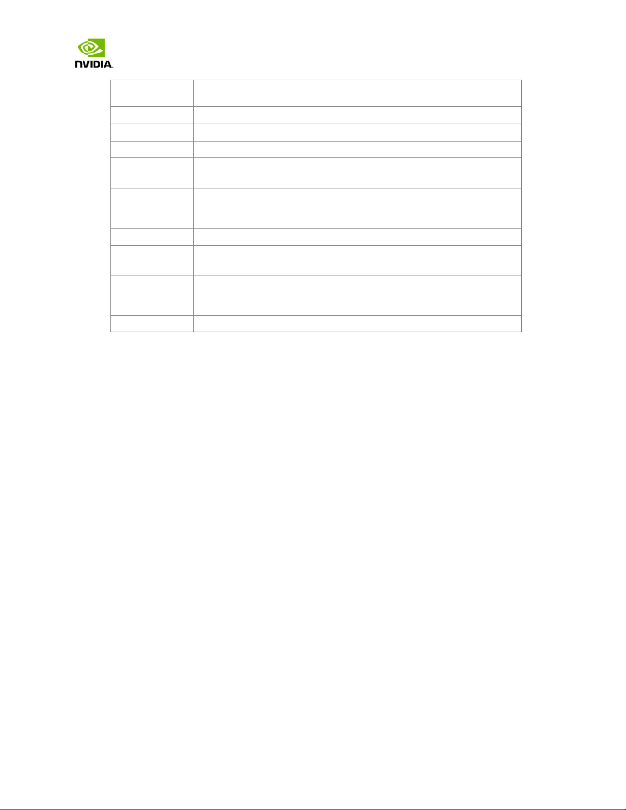
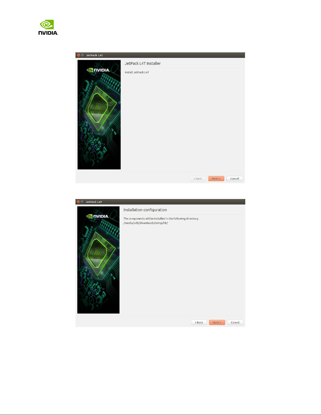
2. Run JetPack-${VERSION}.run in terminal on your host Ubuntu machine.
3. Next, the JetPack installer will indicate the installation directory.
Jetson | Copyright © 2014 NVIDIA Corporation. All rights reserved. Page 9 of 27
Page 10

Jetson TX1 Developer Kit
User Guide
4. Select the development environment to setup.
5. The JetPack installer will pop up a window to ask for permission to use during the
installation process; you will need to enter your sudo password here.
Jetson | Copyright © 2014 NVIDIA Corporation. All rights reserved. Page 10 of 27
Page 11

Jetson TX1 Developer Kit
User Guide
6. The Component Manage r opens, which allows you t o cus to mi ze w hich component s t o ins t al l.
Select the Jetson Developer Kit you would like to develop for to customize the installation
components for each device. Jetson TK1 Developer Kit, Jetson TX1 Developer Kit, and
Jetson TX1 Developer Kit support are available.
NOTE: To run a standalone Ubuntu install, deselect Jetson target specific entries.
Jetson | Copyright © 2014 NVIDIA Corporation. All rights reserved. Page 11 of 27
Page 12

Jetson TX1 Developer Kit
User Guide
7. Accept the license agreement for the selected components.
8. The Component Manager will proceed with the installation. Once the host installation steps
are completed, click the Next button to continue with the installation of target
components.
Jetson | Copyright © 2014 NVIDIA Corporation. All rights reserved. Page 12 of 27
Page 13

Jetson TX1 Developer Kit
User Guide
NOTE: JetPack will now proceed with setting up the Jetson Developer Kit target, if the
corresponding components were selected (i.e., flashing the OS and pushing components to
the Jetson Developer Kit target).
9. If you deselected Flash OS in the Component Manager, you will need to enter the IP
address, user name, and password to set up an ssh connection to the target device.
After you enter the required information and click Next, JetPack will begin installing
components on the target device.
Jetson | Copyright © 2014 NVIDIA Corporation. All rights reserved. Page 13 of 27
Page 14

Jetson TX1 Developer Kit
User Guide
10. If you selected Flash OS in the Component Manager, you will need to select the network
layout for your specific environment.
11. If you selected the Device access Internet via router/switch layout, you will be asked to
select which interface to use for Internet access.
Jetson | Copyright © 2014 NVIDIA Corporation. All rights reserved. Page 14 of 27
Page 15

Jetson TX1 Developer Kit
User Guide
12. If you selected the Device get IP assigned by DHCP server on host and access Internet via
host machine layout, you must select which interface is to be used for Internet access, and
which is to be used for the target interface.
13. A pop-up window will instruct you to put your device into Force USB Recovery Mode, so you
can flash the OS.
14. Next, you will be prompted to install components on the specific target machine, and to
compile samples.
Jetson | Copyright © 2014 NVIDIA Corporation. All rights reserved. Page 15 of 27
Page 16

Jetson TX1 Developer Kit
User Guide
15. After the post installation tasks have been completed, the installation will be complete.
Jetson | Copyright © 2014 NVIDIA Corporation. All rights reserved. Page 16 of 27
Page 17

Jetson TX1 Developer Kit
User Guide
Compiling
JetPack TX1 automatically compiles all samples if “Compile Samples” was checked during components
selection. If you selected CUDA components, CUDA samples will be found in the following directory:
<JetPack_Install_Dir>/NVIDIA_CUDA-<version>_Samples directory.
You could recompile the samples by running:
SMS=53 EXTRA_LDFLAGS=--unresolved-symbols=ignore-in-shared-libs
TARGET_ARCH=aarch64 make
Jetson | Copyright © 2014 NVIDIA Corporation. All rights reserved. Page 17 of 27
Page 18

Jetson TX1 Developer Kit
User Guide
Run JetPack TX1 Samples
The CUDA samples directory will be copied to the home directory on your device by JetPack. The built
binaries can be found in the following directory:
/home/ubuntu/NVIDIA_CUDA-<version>_Samples/bin/aarch64/linux/release/
Run them by calling them in terminal, or double-clicking on them in the file browser. For example,
when you run the oceanFFT sample, the following screen will be displayed.
Jetson | Copyright © 2014 NVIDIA Corporation. All rights reserved. Page 18 of 27
Page 19

Jetson TX1 Developer Kit
User Guide
Compliance
The NVIDIA® Jetson TX1 Developer Kit is compliant with the regulations listed in this section. Compliance
marks, including the FCC and IC ID numbers, can be found at
http://developer.nvidia.com/embedded-computing
United States
Federal Communications Commission (FCC)
FCC ID: LDKNVTX11697
This device complies with part 15 of the FCC Rules. Operation is subject to the following two conditions: (1) this
device may not cause harmful interference, and (2) this device must accept any interference received, including
any interference that may cause undesired operation of the device.
This equipment has been tested and found to comply with the limits for a Class B digital device, pursuant to Part
15 of the FCC Rules. These limits are designed to provide reasonable protection against harmful interference in a
residential installation. This equipment generates, uses and can radiate radio frequency energy and, if not installed
and used in accordance with the instructions, may cause harmful interference to radio communications. However,
there is no guarantee that interference will not occur in a particular installation.
If this equipment does cause harmful interference to radio or television reception, which can be determined by
turning the equipment off and on, the user is encouraged to try to correct the interference by one or more of the
following measures:
• Reorient or relocate the receiving antenna.
• Increase the separation between the equipment and receiver.
• Connect the equipment into an outlet on a circuit different from that to which the receiver is
connected.
• Consult the dealer or an experienced radio/TV technician for help.
FCC Warning: The FCC requires that you be notified that any changes or modifications to this device not expressly
approved by the manufacturer could void the user’s authority to operate the equipment.
RF Radiation Exposure Statement
This equipment complies with FCC RF radiation exposure limits set forth for an uncontrolled environment. This
equipment should be installed and operated with a minimum distance of 20 centimeters between the radiator and
your body.
Only those antennas with same type and lesser/equal gain filed under this FCC ID number can be used with this
device.
Jetson | Copyright © 2014 NVIDIA Corporation. All rights reserved. Page 19 of 27
Page 20

Jetson TX1 Developer Kit
Ant.
Brand
Model Name
Antenna Type
Connector
1
Shanghai Amphenol Airwave
Ci8717-15-000-R
PCB Antenna
Reversed-SMA
2
Shanghai Amphenol Airwave
Ci8717-15-000-R
PCB Antenna
Reversed-SMA
3
Shanghai Amphenol Airwave
Ci8210-15-000-R-TA
PCB Antenna
I-PEX
4
Shanghai Amphenol Airwave
Ci8211-15-000-R
PCB Antenna
I-PEX
5
Shanghai Amphenol Airwave
CI9808-15-000-R
PCB Antenna
I-PEX
6
Shanghai Amphenol Airwave
CI9809-15-000-R
PCB Antenna
I-PEX
7
Shanghai Amphenol Airwave
CI9811-15-000-R
PCB Antenna
I-PEX
8
Shanghai Amphenol Airwave
CI9810-15-000-R
PCB Antenna
I-PEX
9
Shanghai Amphenol Airwave
CI9812-15-000-R
PCB Antenna
I-PEX
10
Shanghai Amphenol Airwave
CI9813-15-000-R
PCB Antenna
I-PEX
Gain (dBi)
2.4G
BT
U-NII-1
U-NII-2A
U-NII-2C
U-NII-3
1
6.02
6.02
5.53
6.48
7.91
5.38
2
6.02
6.02
5.53
6.48
7.91
5.38
3
-2.3
-2.3
2.5
2.9 3 3.2
4
-2.1
-2.1
1.2
1.7
3.2
4.1
5 - -
-7.8
-7.8
-6.5
-5
6 - -
-5.9
-5.7
-4.5
-3.1
7 - -
-6.5
-6.1
-4.1
-3.7
8 - -
-6.1
-5.7
-4.6
-3.3
9 - -
-6.1
-7.6
-4.8
-4
10 - -
-6.1
-7.6
-4.8
-4
User Guide
This radio transmitter [FCC ID: LDKNVTX11697] has been approved by FCC to operate with the antenna types listed
below, with the maximum permissible gain indicated. Antenna types not included in this list that have a gain
greater than the maximum gain indicated for any type listed are strictly prohibited for use with this device.
Ant.
The module is limited to OEM installation ONLY.
This module is intended for OEM integrators under the following conditions:
1. This module is restricted to installation in products for use only in mobile and fixed applications.
2. The antenna(s) used for this transmitter must be installed to provide a separation distance of at least 20 cm
from all persons.
3. The antenna(s) used for this transmitter must not transmit simultaneously with any other antenna or
transmitter.
4. OEM integrator has be limited the operation channels in channel 1-11 for 2.4GHz band.
5. Fixed outdoor applications for point to multipoint operations are subject to the conditions in Part
15.407(a)(1)(i).
Jetson | Copyright © 2014 NVIDIA Corporation. All rights reserved. Page 20 of 27
Page 21

Jetson TX1 Developer Kit
User Guide
The OEM integrator is still responsible for
1. ensuring that the end-user has no manual instructions to remove or install module
2. the FCC compliance requirement of the end product, which integrates this module.
3. Appropriate measurements (e.g. 15 B compliance) and if applicable additional equipment authorizations (e.g.
Verification, Doc) of the host device to be addressed by the integrator/manufacturer.
4. The separate approval is required for all other operating configurations, including portable configurations with
respect to Part 2.1093 and different antenna configurations
Guidance to the Host Manufacturer:
We hereby acknowledge our responsibility to provide guidance to the host manufacturer in the event that
they require assistance for ensuring compliance with the Part 15 Subpart B requirements.
The user manual of the end product should include
1. Any changes or modifications not expressly approved by the party responsible for compliance could void the
user's authority to operate this equipment.
2. the restriction of operating this device in indoor could void the user’s authority to operate the equipment.
3. This device and its antenna(s) must not be co-located or operating in conjunction with any other antenna or
transmitter.
4. This equipment should be installed and operated with minimum distance 20cm between the radiator & your
body.
5. The FCC part 15.19 statement: This device complies with part 15 of the FCC Rules. Operation is subject to the
following two conditions: (1) This device may not cause harmful interference, and (2) this device must accept
any interference received, including interference that may cause undesired operation.
Label of the end product:
The final end product must be labeled in a visible area with the following " Contains TX FCC ID: LDKNVTX11697
".
The end product shall bear the following 15.19 statement: This device complies with part 15 of the FCC Rules.
Operation is subject to the following two conditions: (1) This device may not cause harmful interference, and
(2) this device must accept any interference received, including interference that may cause undesired
operation.
If the labelling area is considered too small and therefore it is impractical (smaller than the palm of the hand)
to display the compliance statement, then the statement may be placed in the user manual or product
packaging.
Underwriters Laboratories (UL)
UL Listed Product Logo for Jetson TX1 Developer Kit, model name P2597.
I.T.E E204896
UL Recognized Component Logo for Embedded System Module, model name P2180.
Jetson | Copyright © 2014 NVIDIA Corporation. All rights reserved. Page 21 of 27
Page 22

Jetson TX1 Developer Kit
Ant.
Brand
Model Name
Antenna Type
Connector
1
Shanghai Amphenol Airwave
Ci8717-15-000-R
PCB Antenna
Reversed-SMA
2
Shanghai Amphenol Airwave
Ci8717-15-000-R
PCB Antenna
Reversed-SMA
3
Shanghai Amphenol Airwave
Ci8210-15-000-R-TA
PCB Antenna
I-PEX
4
Shanghai Amphenol Airwave
Ci8211-15-000-R
PCB Antenna
I-PEX
5
Shanghai Amphenol Airwave
CI9808-15-000-R
PCB Antenna
I-PEX
6
Shanghai Amphenol Airwave
CI9809-15-000-R
PCB Antenna
I-PEX
7
Shanghai Amphenol Airwave
CI9811-15-000-R
PCB Antenna
I-PEX
8
Shanghai Amphenol Airwave
CI9810-15-000-R
PCB Antenna
I-PEX
9
Shanghai Amphenol Airwave
CI9812-15-000-R
PCB Antenna
I-PEX
10
Shanghai Amphenol Airwave
CI9813-15-000-R
PCB Antenna
I-PEX
User Guide
Canada
Industry Canada (IC)
IC: 2461N-NVTX11697
CAN ICES-3(B)/NMB-3(B)
This device complies with Industry Canada’s licence-exempt RSSs of the Industry Canada Rules. . Operation is
subject to the following two conditions: (1) this device may not cause interference, and (2) this device must accept
any interference, including interference that may cause undesired operation of the device.
5150–5250 MHz is only for indoor use to reduce the potential for harmful interference to co-channel
mobile satellite systems;
Ce dispositif est conforme à la norme RSS-247 d'Industrie Canada applicable aux appareils radio
exempts de licence. Son fonctionnement est sujet aux deux conditions suivantes: (1) le dispositif ne
doit pas produire de brouillage préjudiciable, et (2) ce dispositif doit accepter tout brouillage reçu, y
compris un brouillage susceptible de provoquer un fonctionnement indésirable.
This radio transmitter [IC: 2461N-NVTX11697] has been approved by Innovation, Science and Economic
Development Canada to operate with the antenna types listed below, with the maximum permissible
gain indicated. Antenna types not included in this list that have a gain greater than the maximum gain
indicated for any type listed are strictly prohibited for use with this device.
Le présent émetteur radio [IC: 2461N-NVTX11697] a été approuvé par Innovation, Sciences et
Développement économique Canada pour fonctionner avec les types d'antenne énumérés ci-dessous et
ayant un gain admissible maximal. Les types d'antenne non inclus dans cette liste, et dont le gain est
supérieur au gain maximal indiqué pour tout type figurant sur la liste, sont strictement interdits pour
l'exploitation de l'émetteur.
Jetson | Copyright © 2014 NVIDIA Corporation. All rights reserved. Page 22 of 27
Page 23

Jetson TX1 Developer Kit
Gain (dBi)
2.4G
BT
U-NII-1
U-NII-2A
U-NII-2C
U-NII-3
1
6.02
6.02
5.53
6.48
7.91
5.38
2
6.02
6.02
5.53
6.48
7.91
5.38
3
-2.3
-2.3
2.5
2.9 3 3.2
4
-2.1
-2.1
1.2
1.7
3.2
4.1
5 - -
-7.8
-7.8
-6.5
-5
6 - -
-5.9
-5.7
-4.5
-3.1
7 - -
-6.5
-6.1
-4.1
-3.7
8 - -
-6.1
-5.7
-4.6
-3.3
9 - -
-6.1
-7.6
-4.8
-4
10 - -
-6.1
-7.6
-4.8
-4
User Guide
Ant.
RF Radiation Exposure Statement:
Jetson Dev Kit has been tested and complies with IC RSS 102 RF radiation exposure limits set forth for an
uncontrolled environment when used with the NVIDIA accessories supplied or designated for this product. To
satisfy IC exposure requirements, a separation distance of at least 20 cm must be maintained between the antenna
of this device and persons during device operation.. The use of any other accessories may not ensure compliance
with IC RSS 102RF exposure guidelines.
Déclaration d'exposition aux radiations:
La Jetson Dev Kit a ete testee conformemment aux normes d’exposition d’emission RF de la IC RSS 102 pour un
environement non controle lors d’utilisation avec les accessoires fournis or recommendes par NVIDIA. Pour
satisfaire aux exigences d'exposition IC, une distance de séparation d'au moins 20 cm doit être maintenue entre
l'antenne de cet appareil et des personnes pendant le fonctionnement de l'appareil. L’utilisation d’accessoires
autres que ceux recommendes par NVIDIA ne guarantis pas la compatibilite avec les normes d’emission RF de la IC
RSS 102.
OEM integrator is still responsible for testing their end product for any additional compliance requirements
required with this module installed (for example, digital device emissions, PC peripheral requirements, etc.).
IMPORTANT NOTE: In the event that these conditions cannot be met (for example certain laptop configurations or
co-location with another transmitter), then the IC authorization is no longer considered valid and the IC No. cannot
be used on the final product. In these circumstances, the OEM integrator will be responsible for re-evaluating the
end product (including the transmitter) and obtaining a separate IC authorization.
Modular OEM Integrator Notice
End Product Labeling
Jetson | Copyright © 2014 NVIDIA Corporation. All rights reserved. Page 23 of 27
Page 24

Jetson TX1 Developer Kit
User Guide
This transmitter module is authorized only for use in device where the antenna may be installed such that 20 cm
may be maintained between the antenna and users. The final end product must be labeled in a visible area with
the following: “Contains transmitter module IC: 2461N-NVTX11697”.
Contient le module d'émission IC: 2461N-NVTX11697
This device is intended only for OEM integrators under the following conditions:
1) The antenna must be installed such that 20cm is maintained between the antenna and users, and
2) The transmitter module may not be co-located with any other transmitter or antenna.
Cet appareil est conçu uniquement pour les intégrateurs OEM dans les conditions suivantes: (Pour utilisation de
dispositif module)
1) L'antenne doit être installée de telle sorte qu'une distance de 20cm est respectée entre l'antenne et les
utilisateurs, et
2) Le module émetteur peut ne pas être coïmplanté avec un autre émetteur ou antenne.
Modular OEM Integrator Notice
IMPORTANT NOTE for OEM integrator:
This module is intended for OEM integrator.
The OEM integrator is still responsible for
1. ensuring that the end-user has no manual instructions to remove or install module
2. the ISED compliance requirement of the end product, which integrates this module.
3. Appropriate measurements and if applicable additional equipment authorizations of the host device to be
addressed by the integrator/manufacturer.
4. The separate approval is required for all other operating configurations, including portable configurations and
different antenna configurations
Taiwan
National Communications Commission
國家通訊傳播委員會
CCXXxxLPyyyZz
注意!
依據 低功率電波輻射性電機管理辦法
Jetson | Copyright © 2014 NVIDIA Corporation. All rights reserved. Page 24 of 27
Page 25

Jetson TX1 Developer Kit
User Guide
第十二條
經型式認證合格之低功率射頻電機,非經許可,公司、商號或使用者均不得擅自變更頻率、加大功率或變更原設計之特
性及功能。
第十四條
低功率射頻電機之使用不得影響飛航安全及干擾合法通信;經發現有干擾現象時,應立即停用,並改善至無干擾時方得
繼續使用。
前項合法通信,指依電信法規定作業之無線電通信。
低功率射頻電機須忍受合法通信或工業、科學及醫療用電波輻射性電機設備之干擾。
模組認證合格標簽 (ID):
“ CCXXxxLPyyyZz
如果使用本模組之平台,無法在外部看見審驗合格標籤時,應在該
平台的外部明顯標示
“內含射頻模組 CCXXxxLPyyyZz.
應避免影響附近雷達系統之操作。
高增益指向性天線只得應用於固定式點對點系統。
電磁波曝露量 MPE 標準值 1mW/cm², 送測產品實測值為: 0.1883 mW/cm².
本公司於說明書中提供所有必要資訊以指導使用者/安裝者正確的安裝及操作。
無線資訊傳輸設備必須具備安全功能,以保護未經授權之一方任意更改軟體進而避免發射機操作於非經認證之頻率、輸
出功率、調變形式或其他射頻參數設定。
Jetson | Copyright © 2014 NVIDIA Corporation. All rights reserved. Page 25 of 27
Page 26

Jetson TX1 Developer Kit
User Guide
Taiwan RoHS Material Content Declaration
Jetson | Copyright © 2014 NVIDIA Corporation. All rights reserved. Page 26 of 27
Page 27

Jetson TX1 Developer Kit
User Guide
© 2017 NVIDIA Corporation. All rights reserved. NVIDIA, the NVIDIA logo, and JETSON DEV
KIT are trademarks and/or registered trademarks of NVIDIA Corporation in the U.S. and other
countries. Other company and product names may be trademarks of the respective companies
with which they are associated.
Jetson | Copyright © 2014 NVIDIA Corporation. All rights reserved. Page 27 of 27
 Loading...