

Page 1
Cisco Small Business
NSS300 Series Smart Storage
ADMINISTRATION
GUIDE
Page 2

CCDE, CCENT, CCSI, Cisco Eos, Cisco Explorer, Cisco HealthPresence, Cisco IronPort, the Cisco logo, Cisco Nurse Connect, Cisco Pulse, Cisco SensorBase, Cisco StackPower,
Cisco StadiumVision, Cisco TelePresence, Cisco TrustSec, Cisco Unified Computing System, Cisco WebEx, DCE, Flip Channels, Flip for Good, Flip Mino, Flipshare (Design), Flip
Ultra, Flip Video, Flip Video (Design), Instant Broadband, and Welcome to the Human Network are trademarks; Changing the Way We Work, Live, Play, and Learn, Cisco Capital,
Cisco Capital (Design), Cisco:Financed (Stylized), Cisco Store, Flip Gift Card, and One Million Acts of Green are service marks; and Access Registrar, Aironet, AllTouch, AsyncOS,
Bringing the Meeting To You, Catalyst, CCDA, CCDP, CCIE, CCIP, CCNA, CCNP, CCSP, CCVP, Cisco, the Cisco Certified Internetwork Expert logo, Cisco IOS, Cisco Lumin,
Cisco Nexus, Cisco Press, Cisco Systems, Cisco Systems Capital, the Cisco Systems logo, Cisco Unity, Collaboration Without Limitation, Continuum, EtherFast, EtherSwitch, Event
Center, Explorer, Follow Me Browsing, GainMaker, iLYNX, IOS, iPhone, IronPort, the IronPort logo, Laser Link, LightStream, Linksys, MeetingPlace, MeetingPlace Chime Sound,
MGX, Networkers, Networking Academy, PCNow, PIX, PowerKEY, PowerPanels, PowerTV, PowerTV (Design), PowerVu, Prisma, ProConnect, ROSA, SenderBase, SMARTnet,
Spectrum Expert, StackWise, WebEx, and the WebEx logo are registered trademarks of Cisco and/or its affiliates in the United States and certain other countries.
All other trademarks mentioned in this document or website are the property of their respective owners. The use of the word partner does not imply a partnership relationship between
Cisco and any other company. (1002R)
© 2011 Cisco Systems, Inc. All rights reserved. OL-21155-04
Page 3

Contents
Chapter 1: Introducing the NAS 8
Benefits 8
Logging In to the NAS 9
Using the Help 10
Approved Vendor List for Drives and UPS Compatibility 10
Chapter 2: Getting Started 11
Before You Begin 11
Getting to Know the NSS300 Series Smart Storage 12
NSS322 12
NSS324 and NSS326 15
Installing the NSS322, NSS324, and NSS326 19
Placement Tips 19
Installing the Disk Drives 19
Locking and Unlocking the Disk Trays 22
Connecting the Equipment 23
Verifying the Hardware Installation 24
Starting NAS Configuration 24
Windows Operating System 25
Mac OS X or Linux Operating System 25
System Configuration Using the Windows Setup Wizard 25
System Configuration Using the LCD Display 30
System Configuration Using Mac OS X or Linux 32
Mapping a Network Drive 33
Mapping a Network Drive from the Setup Wizard 33
Mapping a Network Drive From Windows 34
Installing the Client Utility for Windows 35
Install the Tool 35
Run the Tool From the CD 36
Remove the Tool 37
Installing the Client Utility for Mac 37
Cisco Small Business NSS300 Series Smart Storage Administration Guide 3
Page 4

Contents
Accessing the Management GUI Using a Web Browser 38
Suggested Next Steps 38
Set Up Services 38
Set Up Backup 39
Set Up Network Shares 39
Reset Network Settings and Password 39
Inline Power Switch Module 40
Chapter 3: Managing the System 42
Status 42
System Information 43
System Service 44
Resource Monitor 47
View Logs 48
Administration 51
General Settings 51
Network 58
Hardware 67
Security 69
Notification 74
Power Management 79
Network Recycle Bin 81
Backup/Restore Settings 83
System Logs Settings 84
Firmware Upgrade 92
Restore to Factory Default 93
Network Service Discovery 94
Users 97
User Groups 102
Disk Management 105
Volume Management 105
RAID Management 111
Cisco Small Business NSS300 Series Smart Storage Administration Guide 4
Page 5

HDD SMART 115
Encrypted File System 117
iSCSI 118
Virtual Disk 132
Contents
Network Shares 133
Share Folders 133
Quota 138
Network Services 140
Microsoft Networking 140
Apple Networking 145
NFS Service 146
FTP Service 148
Telnet/SSH 150
SNMP Settings 151
Web Server 152
Remote Access 156
Applications 164
Web File Manager 164
Accessing the Web File Manager 166
Using the Web File Manager 167
Multimedia Station 172
Download Station 186
Accessing the Download Station 187
Using the Download Station 187
iTunes Server 190
UPnP Media Server 191
MySQL Server 192
PKG Plugins 193
Syslog Server 194
RADIUS Server 197
Backup 202
External Drive 202
Cisco Small Business NSS300 Series Smart Storage Administration Guide 5
Page 6

USB One Touch Copy 204
Remote Replication 205
Time Machine 207
Mozy Backup 209
Contents
External Device 229
External Storage Device 229
UPS Settings 231
Chapter 4: Configuring the NAS for Active Directory Authentication 234
Before You Begin 234
Joining the NAS to Your Domain 235
Configuring Date and Time 235
Configuring DNS Settings 236
Configuring Microsoft Networking 237
Chapter 5: NAS Maintenance 241
Restart or Shut Down the NAS 242
Hardware System Reset 242
Basic System Reset (3 seconds) 244
Advanced System Reset (10 seconds) 245
Disk Failure or Malfunction 245
Power Outage or Abnormal Shutdown 247
System Software Abnormal Operation 247
System Temperature Protection 247
Product Battery Replacement 248
Chapter 6: Troubleshooting Abnormal RAID Operation 249
Before You Begin the Troubleshooting Process 249
Troubleshooting Abnormal RAID Operation of Your NAS 250
Chapter 7: Using the LCD Display 252
Cisco Small Business NSS300 Series Smart Storage Administration Guide 6
Page 7

Contents
System Configuration Using the LCD Display 252
Viewing System Information Using the LCD Display 256
TCP/ IP 256
Physical Disk 257
Volume 258
System 259
Shut Down 259
Reboot 260
Password 260
Back 261
System Messages 261
Appendix A: Specifications 262
Appendix B: Where to Go From Here 264
Cisco Small Business NSS300 Series Smart Storage Administration Guide 7
Page 8

Introducing the NAS
The Cisco Network Attached Storage, or NAS, is a data storage device that is
connected to a network and provides network access to the data stored on it. The
NAS provides centralized data storage for backup and collaboration. Users can
access data from devices on the local network or from remote locations. The NAS
has many data protection and high availability features to assure data is always
protected.
1
Benefits
The NAS is a high-performance network storage device that targets the needs of
small business. There are three models of the NAS based on the number of disks
that they can support internally.
• 2-Bay Desktop Network Storage System (NSS322)
• 4-Bay Desktop Network Storage System (NSS324)
• 6-Bay Desktop Network Storage System (NSS326)
Each NAS model provides the following benefits:
• Next generation protocol Internet Protocol version 6 (IPv6)
• Data protection in the form of Redundant Array of Independent Disks (RAID)
• UPnP DLNA Media Server
• Command line remote access
• iSCSI target feature
• Email or SMS alert integration for remote notification
• One Touch backup button on the front of the NAS
• Ability to transfer and sync data connected to USB devices
Cisco Small Business NSS300 Series Smart Storage Administration Guide 8
Page 9

Introducing the NAS
Logging In to the NAS
• Mozy online backup
• WebDAV/HTTP access to shares
• Included applications, such as WordPress, and the capabilility to have more
added.
Logging In to the NAS
You can log in to the NAS from your web browser.
NOTE You must know the IP address of your NAS log in. If your NAS is equipped with an
LCD display, you can find it there. Otherwise, you can determine the IP address from
the device that issued the IP address to the NAS.
1
To log in to your NAS:
STEP 1 Start a web browser. In the Address bar, enter the IP address of the device on port
8080: for example, http://192.168.0.100:8080.
STEP 2 When the login window opens, enter the administrator account username and
password.
The default username is admin. The default password is admin.
Username and password are case sensitive.
STEP 3 If necessary, choose your language from the Language menu.
STEP 4 Click SSL Login to login using SSL.
STEP 5 Click Login.
NOTE If you are logging in to the NAS for the first time, you will be prompted to change the
admin password.
Cisco Small Business NSS300 Series Smart Storage Administration Guide 9
Page 10

Introducing the NAS
Using the Help
Using the Help
NOTE The term “content-sensitive help” means you have instant access to specific help
STEP 1 Go to a window for which you desire online help.
STEP 2 From the top right of the open window, click Help. A new help window opens for
1
Online, content-sensitive help is built-in to the NAS interface and is always
available to help you understand the rich features of the NAS.
content regarding the window that is currently opened. This makes it quicker to find
the answers that you need.
To access content-sensitive, online help:
and provides online help information for that specific feature.
STEP 3 After reading online help, you can close the help window.
Approved Vendor List for Drives and UPS Compatibility
The Cisco Small Business Smart Storage Approved Disk Drive List provides
recommendations for compatible hard drives, UPS, and external enclosure for use
in the NSS322, NSS324, and NSS326 Series of Network Attached Storage (NAS)
products. Cisco recommends using enterprise-class hard drives that are rated for
24 x 7 applications. If you are using an external USB or eSATA drive or enclosure
that is not on the AVL list, you may be able to read and write to it but for complete
feature support and long term data integrity, we recommend a drive or enclosure
that has been fully tested and approved.
For more information, see the Cisco Small Business Smart Storage Approved
Disk Drive List.
Cisco Small Business NSS300 Series Smart Storage Administration Guide 10
Page 11

Getting Started
This chapter describes the front and back panels of the NAS, how to physically
install your NAS, and how to configure your NAS using the Cisco Setup Wizard or
LCD panel. If you are a new NAS user, we recommend that you to use the Setup
Wizard that is available on the product CD.
The Setup Wizard will help you with:
• Installing the Disk Drives
2
Before You Begin
Before you begin the installation, make sure that you have the following equipment
and services:
• Connecting the Equipment
• Starting NAS Configuration
• Mapping a Network Drive
• Installing the Client Utility for Windows
• Installing the Client Utility for Mac
• Internet connectivity (optional).
• Small Phillips screwdriver.
• Ethernet switch or router.
• 1-6 SATA 2.5-inch disk drives or 3.5-inch disk drives (not included with
some models). It is not required that the disk drives be the same physical
size.
• Uninterruptible Power Supply (UPS), with a USB connection, which is able
to supply power for 10 minutes or more with at least 350 watts of capacity.
Strongly recommended to provide backup power and reduce the risk of
Cisco Small Business NSS300 Series Smart Storage Administration Guide 11
Page 12
Getting Started
277555
LAN
HDD2
HDD1
eSATA
NSS 322
1
2
3
4
5
Smart Storage
Getting to Know the NSS300 Series Smart Storage
system damage after power interruptions. After the initial installation of the
NAS device, see UPS Settings, page 231 to configure the NAS to
communicate with the UPS.
• Properly grounded anti-static wrist strap (recommended).
Getting to Know the NSS300 Series Smart Storage
The following sections describe the physical features of the NSS322, NSS324,
and NSS326 Smart Storage devices.
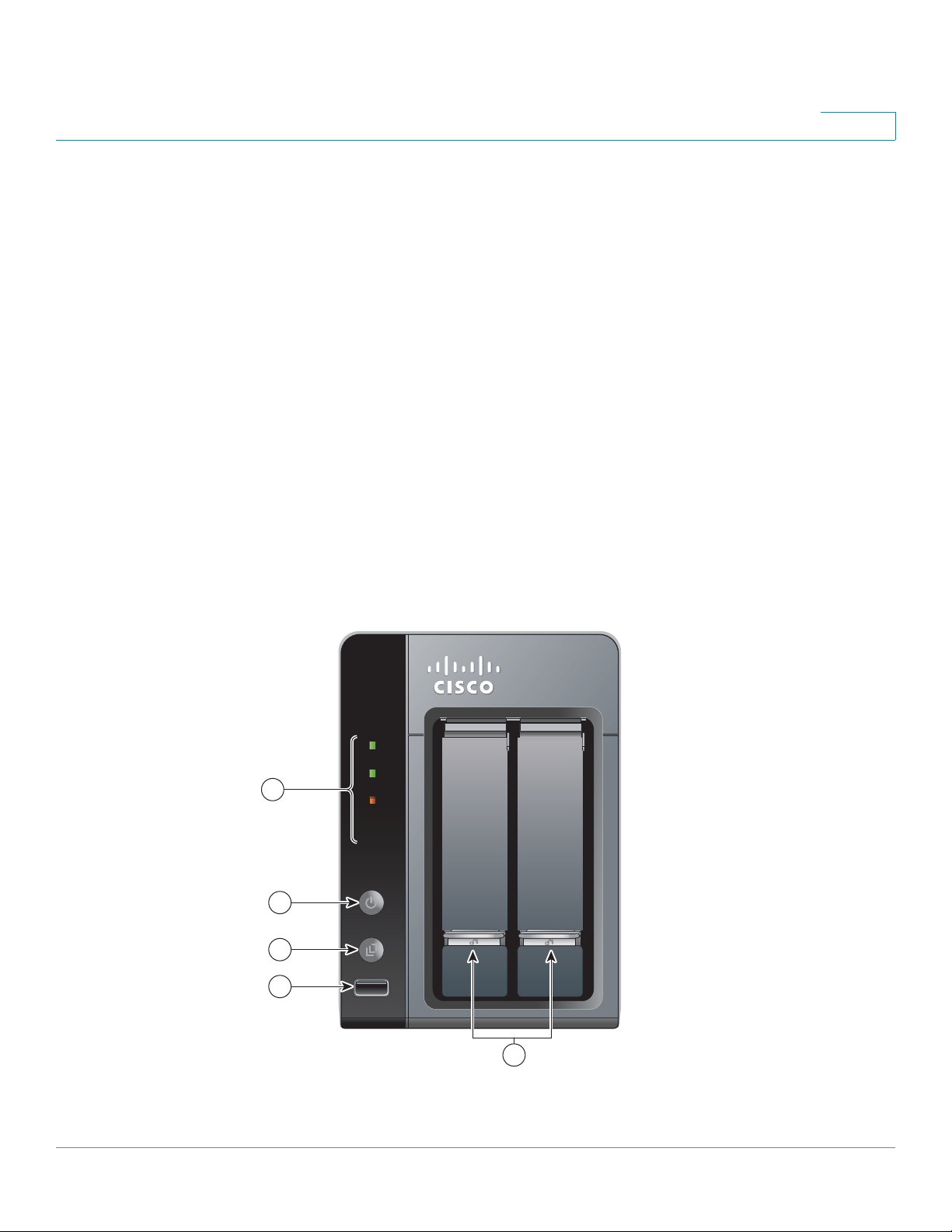
NSS322
2
The following section describes the front and back panels of the NSS322 Smart
Storage.
Front Panel
Cisco Small Business NSS300 Series Smart Storage Administration Guide 12
Page 13

Getting Started
Getting to Know the NSS300 Series Smart Storage
NSS322 Indicators
Number LED Indicator Description
1HDD1, HDD2 • (Green) Flashes green when the disk drive
LAN (Orange) Flashes when there is network traffic to or
eSATA (Orange) Flashes orange when an eSATA device is
2Power • (Off) Disk drives are in standby mode or the
2
data is accessed. Solid green when the disk
drive is accessible.
• (Red) A hard drive read/write error occurs.
from the NAS. Solid orange when the NAS is
connected to the network.
being accessed.
device is powered off.
• (Solid Green) The NAS is ready.
• (Flashing Green) One or more of the
following conditions apply:
- The NAS is starting up.
- The NAS is not configured.
- Disk drive is not formatted.
• (Flashing Red) The NAS is in degraded
mode. One of the disk drives failed in RAID 1
configuration.
3 One Touch Copy (Blue) USB device is detected.
NSS322 Front Panel Buttons
Number Item Description
2 Power Button Press Power to power on or shutdown the
NAS.
3 One Touch Copy
Button
Press One Touch Copy to copy files to or from
an external USB drive.
Cisco Small Business NSS300 Series Smart Storage Administration Guide 13
Page 14
Getting Started
277556
8
1
2
5
7
6
4
3
Getting to Know the NSS300 Series Smart Storage
NSS322 Front Panel Buttons
Number Item Description
4 USB 2.0 USB port for accessing external
5 Disk Tray Lock Lift the silver tab up to lock the disk tray. Press
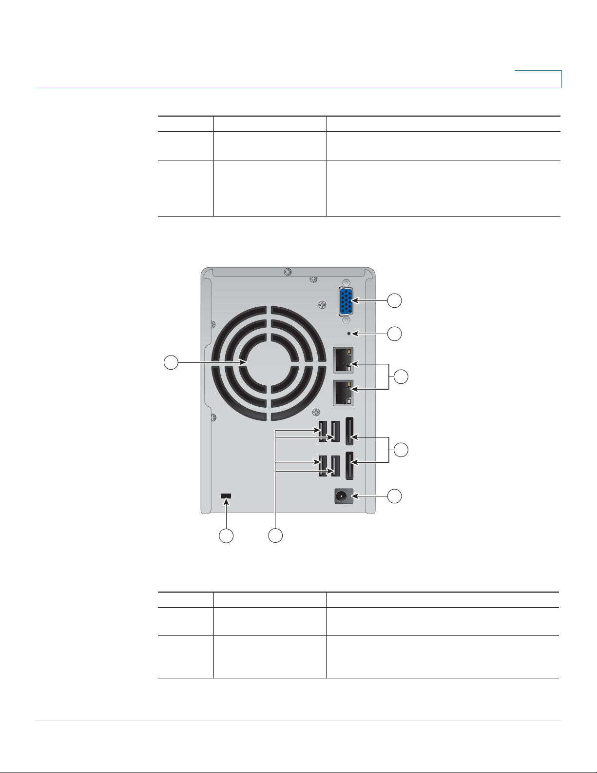
Back Panel
2
USB-attached storage.
the silver tab down to unlock the disk tray.
See Locking and Unlocking the Disk Trays,
page 22.
Cisco Small Business NSS300 Series Smart Storage Administration Guide 14
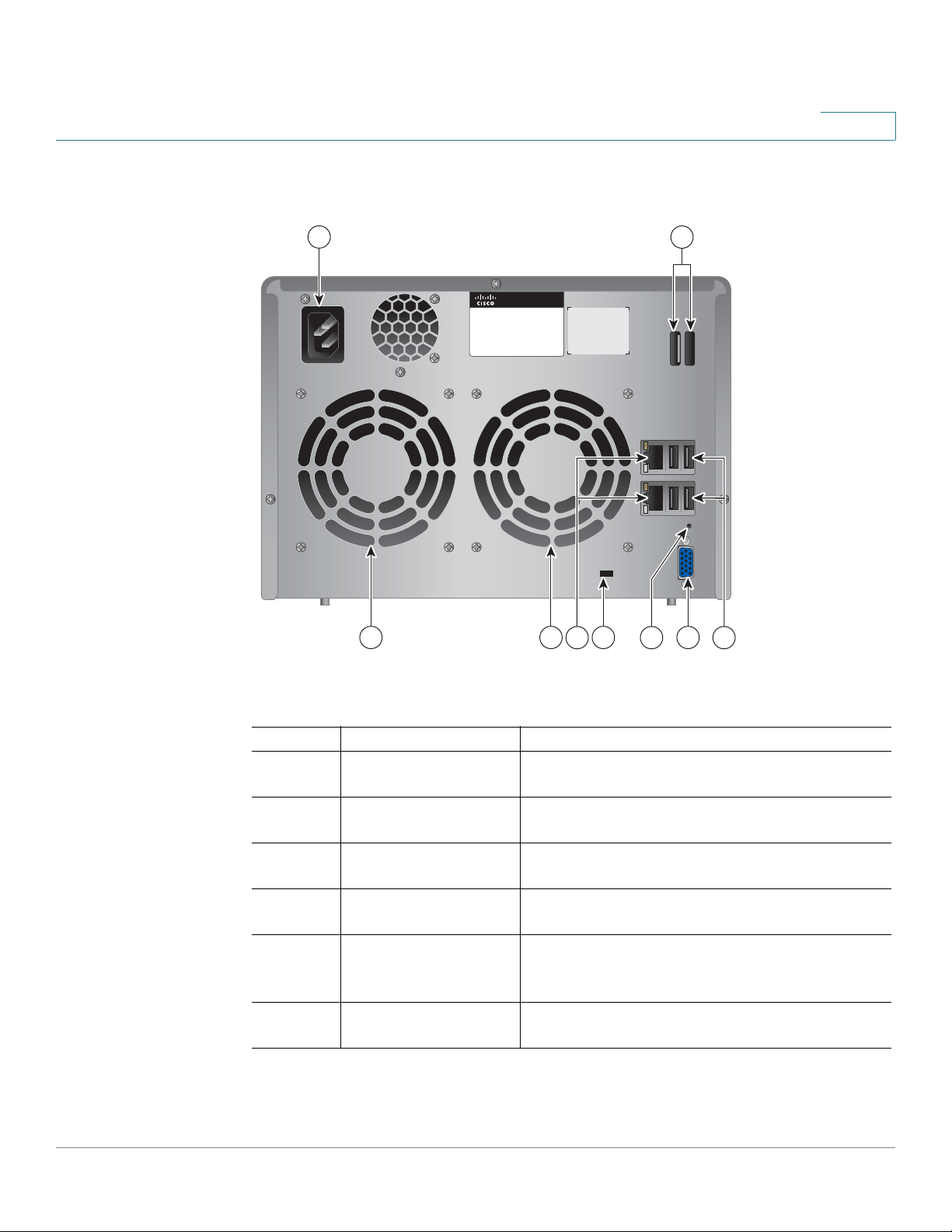
NSS322 Back Panel
Number Item Description
1 VGA Console output to VGA monitor. Used for
2 Reset Restores the network settings and password
device recovery.
to the factory. See Reset Network Settings
and Password, page 39.
Page 15

Getting Started
Getting to Know the NSS300 Series Smart Storage
NSS322 Back Panel
Number Item Description
3 Ethernet Port (2) Dual Ethernet ports. The top LAN port is LAN1
4 eS ATA (2 ) eS ATA po r ts for a c c e s s i n g ex te r n a l e S ATA -
5 Power Connector Connects the device to the external power
6 USB 2.0 (4) USB port for accessing USB attached storage
7 Kensington Lock Slot Attach a Kensington lock to protect the device
8Fan System fan.
2
and the bottom LAN port is LAN2.
attached storage. Use eSATA connector.
adapter, which connects to a standard power
outlet.
and UPS status.
from theft.
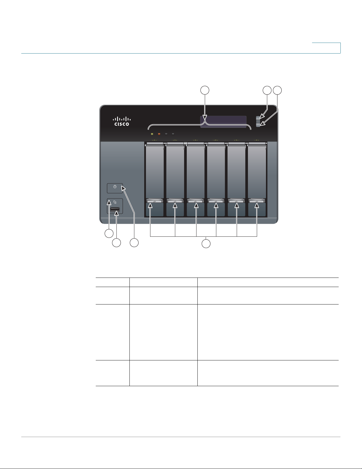
NSS324 and NSS326
The following sections describe the front and back panels of the NSS324 and
NSS326. The front and back panels of the NSS326 are shown.
Cisco Small Business NSS300 Series Smart Storage Administration Guide 15
Page 16
Getting Started
Getting to Know the NSS300 Series Smart Storage
Front Panel
2
Smart Storage
NSS 326
1
2
3
STATUS LAN USB eSATA
4
7
5 6
ENTER
SELECT
277509
NSS324 and NSS326 Indicators
Number Led Indicator Description
1 One Touch Copy
(Blue) USB device is detected.
Button
4 Status (Red) Flashes red when the device is
initialized and the disk drives are being
formatted.
(Green) Flashes green when the disk drives
are not initialized. Solid green when the NAS
is powered up and finished booting.
LAN (Orange) Flashes when there is network
traffic to or from the NAS. Solid orange when
the NAS is connected to the network.
Cisco Small Business NSS300 Series Smart Storage Administration Guide 16
Page 17

Getting Started
Getting to Know the NSS300 Series Smart Storage
NSS324 and NSS326 Indicators
Number Led Indicator Description
eSATA (Orange) Flashes orange when an eSATA
HDD (Green) Flashes green when the disk drive
NSS324 and NSS326 Front Panel Buttons
Number Item Description
1 One Touch Copy Press One Touch Copy to copy files to or from
2 USB 2.0 USB port for accessing external
3 Power Press Power to power on or shutdown the
5 Enter Displays options for configuration or status
6 Select Press Select to confirm a configuration or
7 Disk Tray Lock Lift the silver tab up to lock the disk tray. Press
2
device is being accessed.
data is accessed. Solid green when the disk
drive is accessible.
(Red) A hard drive read/write error occurs.
an external USB drive.
USB-attached storage.
device.
such as bootup progress, disk configuration,
and volume. After configuration, you can view
the hostname and IP address.
menu option.
the silver tab down to unlock the disk tray.
See Locking and Unlocking the Disk Trays,
page 22.
Cisco Small Business NSS300 Series Smart Storage Administration Guide 17
Page 18
Getting Started
Getting to Know the NSS300 Series Smart Storage
Back Panel
2
1
Model No.: NSS326
Smart Storage
7 3
688
2
277510
5
4
NSS324 and NSS326 Back Panel
Number Item Description
1 Power Connector Connects the device to a standard power
outlet.
2 eS ATA (2 ) eS ATA po r ts for a c c e s s i n g ex te r n a l e S ATA -
attached storage. Use eSATA connector.
3 USB 2.0 (4) USB port for accessing USB-attached
storage and UPS status.
4 VGA Console output to VGA monitor. Used for
device recovery.
5 Reset Restores the network settings and password
to the factory default. See Reset Network
Settings and Password, page 39.
6 Kensington Lock Slot Attach a Kensington lock to protect the device
from theft.
Cisco Small Business NSS300 Series Smart Storage Administration Guide 18
Page 19
Getting Started
!
Installing the NSS322, NSS324, and NSS326
NSS324 and NSS326 Back Panel
Number Item Description
7 Ethernet Port (2) Dual Ethernet ports. The top LAN port is LAN1
and the bottom LAN port is LAN2.
8Fan System fan(s).
NOTE: The NSS324 has one fan.
Installing the NSS322, NSS324, and NSS326
Please place your NSS322, NSS324, or NSS326 on a desktop or flat surface.
Placement Tips
2
• Ambient Temperature—To prevent the device from overheating, do not
operate it in an area that exceeds an ambient temperature of 104°F (40°C).
• Air Flow—Be sure that there is adequate air flow around the device. Avoid
any obstructions to air flow either in front of or behind the chassis.
• Mechanical Loading—Be sure that the device is level and stable to avoid
any hazardous conditions. Do not place any other devices on top of the
NAS.
• Vibration/Impacts—Be sure that the device is installed in a location where
it will not be subject to vibration or impact because this can cause a
mechanical shock and premature drive failures.
Installing the Disk Drives
CAUTION When storing unused disk drives, do not stack multiple disk drives because this can
cause drive failures.
When installing the disk drives, follow the suggestions in
Discharge and Grounding Best Practices
Cisco Small Business NSS300 Series Smart Storage Administration Guide 19
, located on the product CD.
Cisco Electrostatic
Page 20

Getting Started
ENTER
277516
ENTER
SELECT
STATUS LAN USB eSATA
NSS 326
Smart Storage
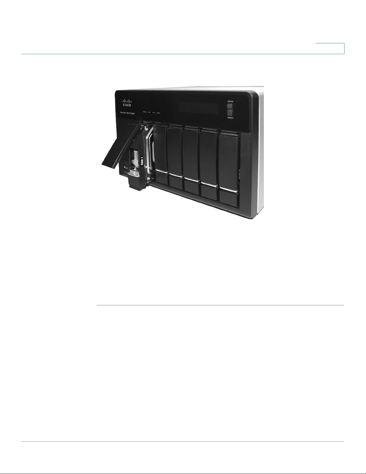
Installing the Disk Drives
STEP 1 Remove the contents of the NAS package from the box.
STEP 2 Place the chassis upright on a flat surface.
STEP 3 From disk bay 1, remove the disk tray.
2
To install disk drives in the NAS chassis:
To remove the disk tray, push the silver tab down to unlock the tray, and push the
lower tab to release the tray lever. Using the tray lever, pull the tray out.
NOTE If your device has the disk drives already installed, continue to the next section,
Connecting the Equipment, page 23.
STEP 4 Position the disk drive into a disk tray. The electrical connectors of the disk drive
must face toward the back of the drive tray.
STEP 5 Attach the disk drive to the tray by inserting the disk drive screws into the four
holes at the bottom of the tray and tightening them with a Phillips screwdriver.
NOTE Use the screws provided in the box with the device. Using other screws can cause
damage to your disk or disk tray.
There are clearly marked disk holes to accommodate the following disk drives:
• 3.5-inch disk drive (use the included silver screws)
• 2.5-inch disk drive (use the included black screws)
Cisco Small Business NSS300 Series Smart Storage Administration Guide 20
Page 21

Getting Started
277517
2.5 inch 3.5 inch
1 2 3 4 5 6
HDD Sequence
Installing the Disk Drives
STEP 6 Insert the tray back in the correct sequence into the empty bay of the chassis.
NOTE Drive trays should not be swapped from slot to slot.
2
There is also an HDD sequence label included in the package contents that can be
placed on the top of the chassis, showing the disk drive sequence. For example,
1-2 for the NSS322, 1-4 for the NSS324, and 1-6 for the NSS326.
Cisco Small Business NSS300 Series Smart Storage Administration Guide 21
Page 22
Getting Started
Locking and Unlocking the Disk Trays
The HDD sequence number is also located on the inside of the disk tray.
2
STEP 7 Using your thumb, apply even pressure to the middle of the tray while you insert
the tray slowly and fully into position in the chassis.
STEP 8 The disk tray lever should be in the open position.
STEP 9 Gently push the disk tray lever down.
STEP 10 Repeat steps 3 through 9 to install disk drives from slot 2 to slot 4 for the NSS324
and slot 2 to slot 6 for the NSS326.
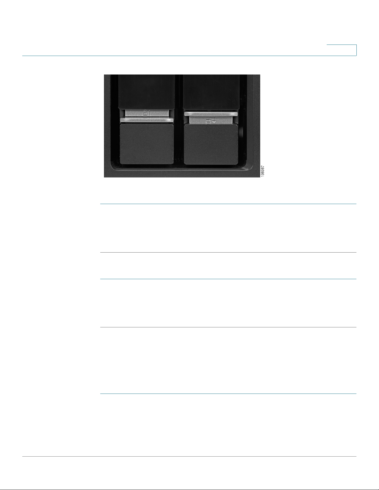
Locking and Unlocking the Disk Trays
An icon is located on the silver tab indicating:
• When the silver tab is up, the disk tray is locked.
• When the silver tab is down, the disk tray is unlocked.
Cisco Small Business NSS300 Series Smart Storage Administration Guide 22
Page 23
Getting Started
Connecting the Equipment
2
To lock the disk tray:
STEP 1 Verify that the disk tray is fully inserted in the chassis with the disk tray lever down.
STEP 2 Lift the silver tab up to lock the tray.
STEP 3 Continue to Connecting the Equipment, page 23.
To unlock and remove the disk tray:
STEP 1 On the disk tray, press the silver tab down to unlock the tray.
STEP 2 Press the button below the silver tab to release the disk tray lever.
STEP 3 Using the disk tray lever, gently pull the disk tray out from the chassis.
Connecting the Equipment
To connect the NAS device to the network:
STEP 1 Connect the supplied Ethernet cable to one of the Ethernet ports on the back of
the chassis.
STEP 2 Connect the other end of the Ethernet cable to a switch or router on your network.
STEP 3 Connect the supplied power cord to the Power port on the back of the chassis.
Cisco Small Business NSS300 Series Smart Storage Administration Guide 23
Page 24

Getting Started
Verifying the Hardware Installation
STEP 4 Plug the other end of the power cord into a battery-backed-up outlet on the UPS,
or a standard power outlet if a UPS is not being used.
STEP 5 To start the NAS, press and release the Power button on the front panel.
Listen for one beep. Wait for one to two minutes until the device beeps another
time.
The device has started successfully. The power light turns solid green when the
NAS is ready to use.
Verifying the Hardware Installation
2
To verify the hardware installation, complete the following tasks:
• Check the cable connections.
• Check the LED states, as described in Getting to Know the NSS300
Series Smart Storage, page 12.
If you encounter problems, consider the following tips:
• If the NAS does not recognize the disk drives, possible causes and
solutions are:
- Confirm the disk drive is supported by Cisco. See the Cisco approved
vendor list at www.cisco.com/go/smallbizsmartstorage.
- Disk tray is installed incorrectly. Try removing and reseating the disk tray.
- Power the device off, then back on to recognize the disk drives.
NOTE If you need help resolving a problem, visit the Cisco Small Business Support
Community at www.cisco.com/go/smallbizsupport. For technical documentation
and other links, see Where to Go From Here, page 264.
Starting NAS Configuration
Before you begin the system configuration, make sure that you have a computer
that meets the following requirements:
Cisco Small Business NSS300 Series Smart Storage Administration Guide 24
Page 25

Getting Started
Starting NAS Configuration
2
• Internet browser connectivity to the NAS (Internet connectivity optional).
The following browsers are supported:
- Microsoft Internet Explorer 7.0 or later
- Mozilla Firefox 3.0 or later
- Apple Safari 3.0 or later
• Supported operating systems:
- Windows 2000, XP, Vista, Server 2003, Server 2008, Windows 7
- Mac OS X 10.4 or later
- Unix or Linux 2.6 or later
Windows Operating System
If you are using a Windows operating system, you can configure the Smart
Storage by using either the Setup Wizard or the LCD display located on the front
panel of the device. See the following sections:
• System Configuration Using the Windows Setup Wizard—For more
advanced users, the Setup Wizard guides you through the initial
configuration settings.
• System Configuration Using the LCD Display—Easier and quicker
installation that uses more default settings. System configuration using the
LCD display is supported on the NSS324 and NSS326.
Mac OS X or Linux Operating System
If you are using a Mac OS X or Linux operating system, see the following sections:
• System Configuration Using Mac OS X or Linux
System Configuration Using the Windows Setup Wizard
After connecting the equipment and pressing the Power button, the system takes
a few minutes to initialize. Listen for one beep. Wait a minute until you hear a
second beep. The power light will turn solid green. The NAS device has started
successfully and you can configure the device using the First Time Installation
Wizard.
Cisco Small Business NSS300 Series Smart Storage Administration Guide 25
Page 26

Getting Started
Starting NAS Configuration
NOTE If you receive Windows firewall warnings during this process, you may need to
STEP 1 Insert the product CD and from the Welcome window and choose your NAS
STEP 2 Under First Time Installation, click Setup. The First Time Installation Wizard
STEP 3 Click Next to launch the wizard. The End-User License Agreement window
STEP 4 To accept the End-User License Agreement, check the I accept this agreement
2
allow the installation application to unblock the firewall settings. If the installation
does not start, you may also need to temporarily disable any security software on
your computer to run the Setup Wizard.
To configure your system using the Setup Wizard:
model. The Setup Menu window opens.
window opens.
opens.
check box and click Next. The Hardware Installation Guide window opens.
STEP 5 Click Next and follow the prompts to check the package contents, install the disk
drives, and connect the equipment.
NOTE If you have already installed the disk drives and connected the equipment, click
Skip until you reach the System Configuration window.
STEP 6 From the System Configuration window, click Next to go to NAS configuration.
The NAS Configuration window opens.
STEP 7 Click Next. The Discovering the NAS window opens and advises when the
uninitialized device is found.
NOTE If your device is already configured, click Skip to go to Map Network Drive. See
Mapping a Network Drive, page 33.
STEP 8 Click Next. The Web Configuration window opens.
STEP 9 The First Time Installation Wizard detects the NAS and prompts you to go through
the web configuration process. From the drop-down list, select a NAS device.
STEP 10 Click Next to continue. You are directed to a web configuration window to
complete the settings step by step. The Welcome window displays.
STEP 11 Click Next. You are redirected to a window where you can enter the name for this
server.
STEP 12 In the Server Name field, enter a name to identify the NAS device.
Cisco Small Business NSS300 Series Smart Storage Administration Guide 26
Page 27

Getting Started
Starting NAS Configuration
STEP 13 Click Next. You are redirected to a window where you can change the
NOTE The default administrator username is admin. The default administrator password
STEP 14 Change the administrator password by entering the new password in the
STEP 15 Click Next. You are redirected to a window where you can enter the date, time,
STEP 16 Enter the date, time, and time zone for this server. The options are:
2
The server name can be a maximum length of 14 characters, which supports
alphanumeric characters (a-z, 0-9) and hyphens (-). It is required that the server
name begin with a letter versus a number. The server name does not accept
names with a space or period (.)
administrator password.
is admin.
Password field. To verify the password, re-enter it in the Verify Password field.
and time zone for the server.
• Time Zone—Select a time zone from the drop-down menu.
• Date/Time—Select the current date and time from the drop-down menus.
• Synchronize with an Internet time server automatically—To obtain time
automatically from an NTP server, click this check box.
• Server—From the drop-down list, select the NTP server name and click
TEST to verify status.
For example:
- time-a.timefreq.bldrdoc.gov (default)
- time-b.timefreq.bldrdoc.gov
- time-c.timefreq.bldrdoc.gov
• Set the server time the same as your computer time—To synchronize the
server time/clock with the time/clock on your computer, click this check box.
STEP 17 Click Next. You are redirected to a window where you can enter the IP address,
subnet mask, and default gateway for the device.
STEP 18 Enter the IP address, subnet mask, and default gateway for this server. You can
either acquire the IP address automatically from a DHCP server or choose to
configure a static IP address.
• Obtain TCP/IP settings automatically via DHCP—Click this check box to
acquire the IP address from a DHCP server. This is enabled by default.
Cisco Small Business NSS300 Series Smart Storage Administration Guide 27
Page 28

Getting Started
Starting NAS Configuration
STEP 19 Click Next. You are redirected to a window where you can select the services to
STEP 20 Select the services to be enabled. These services can also be enabled or
2
• Click Use the following settings to configure a static IP address:
- IP Address—Enter an IP address for the NAS.
- Subnet Mask—Enter the subnet mask of your network.
- Default Gateway—Enter the default gateway address. This is typically
the IP address of your router.
- Primary DNS Server (optional)—Enter the IP address of the Domain
Name System (DNS) server. This address is typically provided by your
Internet Service Provider (ISP).
- Secondary DNS Server (optional)—Enter a second DNS server.
be enabled.
disabled at a later time. The options are:
• Network services—Click the check box to enable Microsoft Networking,
Apple Networking, or Unix/Linux NFS.
• File services—Click the check box to enable Web File Manager, FTP
Service, or Download Station.
• Multimedia services—Click the check box to enable Multimedia Station,
UPnP multimedia server, or iTunes service.
• Web server services—Click the check box to enable Web Server or MySQL
server.
STEP 21 Click Next. You are redirected to a window where you can select the disk
configuration.
STEP 22 Select the disk configuration.
NOTE It is recommended to configure the NSS324 or NSS326 with RAID 5 if there are
three or more disks installed.
• Disk configuration:
The following options are available:
- Do not set disk configuration—If you have created disk volume
configuration or plan to create multiple disk configurations, select not to
initialize the disk drives.
Cisco Small Business NSS300 Series Smart Storage Administration Guide 28
Page 29

Getting Started
Starting NAS Configuration
2
- Single Disk—Uses the disk drives as single disk volumes. When a drive
failure occurs, all data is lost.
- JBOD (Linear)—JBOD lets you combine multiple disks of mixed
capacities into a single logical storage device. The capacity of the JBOD
array is the sum of the total capacities of the individual component disks
(that is, it does not have the limitation of RAID 1 where you lose some
capacity when using mixed sized disks). JBOD offers no performance
increase compared to the component disks. It has lower reliability than
the component disks, as the failure of a single disk results in the failure of
the whole array.
- RAID 0—Distributes data across several disks in a way that improves
speed and full capacity. All data on all disks will be lost if any single disk
fails.
- RAID 1—Uses two disks (mirrored disks) each of which store the same
data, so that data is not lost as long as one disk survives. Total capacity of
the array equals the capacity of the smaller disk.
- RAID 5—Combines three or more disks in a way that protects data
against loss of any single disk. RAID 5 is applicable to NSS324 and
NSS326.
- RAID 6—Combines four or more disks in a way that protects data against
loss of any two disks. RAID 6 is applicable to NSS324 and NSS326.
• File system:
- EXT4—EXT4 is the successor to EXT3 and provides better performance
because the EXT4 file system can support very large volumes (default).
- EXT3—EXT3 is commonly used in the Linux environment. EXT3 provides
reliable file systems with a maximum capacity support up to
16 terabytes (TB).
• Encrypt disk volume:
- No—Do not encrypt the disk volume (default).
- Yes —Encrypt the disk volume using a password.
Cisco Small Business NSS300 Series Smart Storage Administration Guide 29
Page 30

Getting Started
Starting NAS Configuration
STEP 23 Click Next. The Finish window displays the server configuration.
STEP 24 Click Start Installation. System begins initializing and the configuration progress
STEP 25 From the Configuring the NAS window, click Next to continue to Map a Network
2
If you choose yes, the disk volume is encrypted with a password and provides an
extra layer of security against the theft of data in the event that disks are stolen.
File transfer performance to encrypted volumes is generally lower than nonencrypted volumes.The default encryption password is the password of the
administrator account.
is displayed.
When the configuration is complete, you are returned to the Configuring the NAS
window in the Setup Wizard.
Drive. The Map Network Drive window opens. Continue to Mapping a Network
Drive, page 33.
System Configuration Using the LCD Display
After connecting the equipment and pressing the Power button, the system boots,
loads the driver, and mounts the volume. You can optionally configure the NAS
device using the options in the LCD display.
NOTE If you have configured the NAS using the Setup Wizard, you do not need to setup
the NAS using the LCD display.
NOTE System configuration using the LCD display is supported on the NSS324 and
NSS326.
Cisco Small Business NSS300 Series Smart Storage Administration Guide 30
Page 31

Getting Started
Starting NAS Configuration
STEP 1 At the prompt Config Disks? in the LCD display, press Select to choose the disk
2
To configure your system using the LCD display:
configuration.
The following options are available:
• Do not set disk configuration—If you have created disk volume
configuration or plan to create multiple disk configurations, select not to
initialize the disk drives.
• Single Disk—Uses the disk drives as single disk volumes. When a drive
failure occurs, all data is lost.
• JBOD (Linear)—JBOD lets you combine multiple disks of mixed capacities
into a single logical storage device. The capacity of the JBOD array is the
sum of the total capacities of the individual component disks (that is, it does
not have the limitation of RAID 1 where you lose some capacity when using
mixed sized disks). JBOD offers no performance increase compared to the
component disks. It has lower reliability than the component disks, as the
failure of a single disk results in the failure of the whole array.
• RAID 0—Distributes data across several disks in a way which that improves
speed and full capacity. All data on all disks will be lost if any single disk fails.
• RAID 1—Uses two disks (mirrored disks) which each store the same data, so
that data is not lost as long as one disk survives. Total capacity of the array
equals the capacity of the smaller disk.
• RAID 5—Combines three or more disks in a way that protects data against
loss of any single disk. RAID 5 is applicable to the NSS324 and NSS326.
• RAID 6—Combines four or more disks in a way that protects data against
loss of any two disks. RAID 6 is applicable to the NSS324 and NSS326.
STEP 2 After choosing the disk configuration, press Enter. The LCD display shows:
Choose <Disk Configuration>
Yes No
Yes i s th e d efa ult .
STEP 3 Press Enter to continue. The LCD display shows:
Encrypt Volume
Yes No
Cisco Small Business NSS300 Series Smart Storage Administration Guide 31
Page 32

Getting Started
Starting NAS Configuration
STEP 4 Press Enter to continue. The system configuration progress is displayed. When
STEP 5 Start a web browser. In the Address bar, enter the IP address of the device that is
STEP 6 When the login window opens, enter the administrator account username and
2
No is the default. If you choose yes, the disk volume is encrypted with a
password and provides an extra layer of security against the theft of data.
The default encryption password is a password of the “admin” account.
the configuration is complete, you will receive an IP address and default NAS
device name that is shown in the LCD display
shown in the LCD display:
http://x.x.x.x:8080
password.
The default username is admin. The default password is admin. Username and
password are case sensitive.
STEP 7 Click Login.
STEP 8 Follow the prompts to change the admin password.
STEP 9 Click Submit.
STEP 10 When the login window opens, enter the administrator account username admin
and the new administrator password.
Continue to Mapping a Network Drive From Windows, page 34.
System Configuration Using Mac OS X or Linux
To configure your system using Mac OS X or Linux:
STEP 1 Connect the NAS to the computer directly and power on the device.
The NAS Ethernet ports support MDI/MDI-X auto-switching.
STEP 2 Verify the IP address of your computer is configured to the same subnet as the
NA S de vi ce . For ex am pl e : 1 92.1 68 .1.1.
STEP 3 Open a web browser and enter the IP address of the NAS device. For example:
http://192.168.1.50:8080
Cisco Small Business NSS300 Series Smart Storage Administration Guide 32
Page 33

Getting Started
Mapping a Network Drive
NOTE If your operating system is Linux, refer to the LCD display on the front panel of the
STEP 4 Follow the prompts to complete the configuration.
2
This is the default static IP address if DHCP is not enabled. If the NAS device does
not have a static IP address and if the device is not able to receive an IP address
via DHCP, it will default to 192.168.1.50. If the DHCP server on your network is
enabled, as soon as the DHCP server responds, the NAS device will accept an IP
address even if the default static IP address is assigned.
NAS device and configure the IP address to match the network. The LCD display is
located on the NSS324 and NSS326.
Continue to Suggested Next Steps, page 38.
Mapping a Network Drive
You can map a network drive either by using the Setup Wizard or from Windows.
Mapping a Network Drive from the Setup Wizard
NOTE Skip steps 1-5 if you are already on the Map Network Drive window in the Setup
Wizard.
To map a network drive from the Setup Wizard:
STEP 1 Insert the product CD and from the Welcome window, click NSS322, NSS324, or
NSS326 depending on which NAS device you are installing. The Setup Menu
window opens.
STEP 2 Under First Time Installation, click Setup. The First Time Installation Wizard
window opens.
STEP 3 Click Next to launch the wizard. The End-User License Agreement window
opens.
STEP 4 To accept the End-User License Agreement, check the I accept this agreement
check box and click Next. The Hardware Installation Guide window opens.
STEP 5 Click Skip until you reach the Map Network Drive window.
Cisco Small Business NSS300 Series Smart Storage Administration Guide 33
Page 34

Getting Started
Mapping a Network Drive
STEP 6 From the Map Network Drive window, click Next to start mapping your network
STEP 7 When the initialized NAS is found, click Next. The Select the NAS Device window
STEP 8 From the drop-down list, select the NAS device that you want to map as a network
STEP 9 Click Next. The Mapping Drives window opens.
STEP 10 From the drop-down lists, select a folder type and select a drive letter to be
2
drive. The Discovering the NAS window opens and the First Time Installation
Wizard searches for your initialized NAS.
opens.
drive.
mapped.
Preconfigured share folders types are:
• Public—Network share for file sharing (default).
• Usb—Network share for data copy function using the USB ports.
• Web—Network share for Web server.
• Download—Network share for Download Station.
• Multimedia—Network share for Multimedia Station.
• Network Recycle Bin 1—Network share recycle bin.
STEP 11 From the authentication login window, enter the administrator account username
and password.
STEP 12 Click Next. The Mapping Success window opens.
STEP 13 Click More to map another drive or click Next to continue to the Client Utility
Installation. See Installing the Client Utility for Windows, page 35.
Mapping a Network Drive From Windows
NOTE If you are using Windows Vista, you might receive a security warning and have to
temporarily disable any security software on your computer.
To map a network drive from Windows:
STEP 1 From the Windows desktop, click the My Computer icon to open My Computer.
STEP 2 Choose To ol s > M ap Ne t w or k D riv e. The Map Network Drive window opens.
Cisco Small Business NSS300 Series Smart Storage Administration Guide 34
Page 35

Getting Started
Installing the Client Utility for Windows
STEP 3 From the drop-down lists, select the drive letter to be mapped.
STEP 4 In the Folder field, type the share name you want to map. For example:
\\<NAS IP address>\<share name>
STEP 5 Click OK.
STEP 6 Click Finish.
NOTE If you are prompted to enter a username and password for authentication, enter the
administrator account username and password.
STEP 7 Open Windows Explorer to view and use the network share as a local drive.
2
Installing the Client Utility for Windows
Installing the Client Utility, or NSS Discovery Tool, is optional. The NSS Discovery
Tool provides functions for you to search, configure, and manage your NAS
devices.
NOTE If you receive Windows firewall warnings during this process, you may need to
allow the NSS Discovery Tool to unblock the firewall settings.
From the NSS Discovery Tool windows, you have the following options:
• Install the Tool
• Run the Tool From the CD
• Remove the Tool
Install the Tool
When installed to your computer, the NSS Discovery Tool acts as a standalone
discovery tool. If you have numerous devices on your network, the NSS Discovery
Tool detects uninitialized and initialized NAS devices.
Cisco Small Business NSS300 Series Smart Storage Administration Guide 35
Page 36

Getting Started
Installing the Client Utility for Windows
To install the NSS Discovery Tool for Windows:
STEP 1 Insert the product CD and from the Welcome window, click NSS322, NSS324, or
NSS326 depending on which NAS device you are installing. The Setup Menu
window opens.
STEP 2 From the Setup menu and under Utility Installation, click Install. The NSS
Discovery Tool Setup window opens.
STEP 3 Click Next.
Select the components to install from the following options:
• Desktop Shortcuts
• Quick Launch Shortcuts
STEP 4 Click Next. The Choose Install Location window opens.
2
STEP 5 Click Install to install to the default folder or click Browse to install to another
folder.
STEP 6 When the Completing the NSS Discovery Tool Setup Wizard window opens,
click Finish.
Run the Tool From the CD
To run the NSS Discovery Tool from the CD:
STEP 1 Insert the product CD and from the Welcome window, click NSS322, NSS324, or
NSS326 depending on which NAS device you are installing. The Setup Menu
window opens.
STEP 2 From the Setup menu and under Utility Installation, click Install. The NSS
Discovery Tool Setup window opens.
STEP 3 Click Install. The NSS Discovery Tool window opens and shows a list of initialized
NAS devices on your network. From this window, you can connect, configure, or
view details for the listed devices.
STEP 4 Click Exit to close the tool.
Cisco Small Business NSS300 Series Smart Storage Administration Guide 36
Page 37

Getting Started
Installing the Client Utility for Mac
Remove the Tool
To remove the NSS Discovery Tool:
STEP 1 Insert the product CD and from the Welcome window, click NSS322, NSS324, or
NSS326 depending on which NAS device you are installing. The Setup Menu
window opens.
STEP 2 From the Setup menu and under Utility Installation, click Remove. The NSS
Discovery Tool Setup window opens.
STEP 3 Click Next.
STEP 4 Click Uninstall. The Uninstall NSS Discovery Tool window opens.
STEP 5 When the Completing the NSS Discovery Tool Uninstall Wizard window opens,
Click Close.
2
Installing the Client Utility for Mac
Installing the Client Utility, or NSS Discovery Tool, is optional. The NSS Discovery
Tool provides functions for you to search, configure, and manage your NAS
devices.
To install the NSS Discovery Tool for Mac:
STEP 1 Insert the product CD.
STEP 2 Double-click the CD icon on the desktop to view the contents in Finder.
STEP 3 From the …\MAC\NSSDiscoveryTool\...folder, click the Setup.dmg file to launch
the Setup Wizard.
STEP 4 The End User License Agreement window opens. If you agree to the terms of the
license, click Agree to install the software.
STEP 5 From the NSS Discovery Tool window, drag the NSS Discovery Tool icon into the
Application folder.
STEP 6 From the Application folder, double-click NSS Discovery Tool to launch the
software. The NSS Discovery Tool window opens. From this window, you can
connect, configure, or view details for the listed devices.
Cisco Small Business NSS300 Series Smart Storage Administration Guide 37
Page 38

Getting Started
Accessing the Management GUI Using a Web Browser
STEP 7 Click Exit to close the tool.
Accessing the Management GUI Using a Web Browser
To access the GUI from a web browser:
STEP 1 Open a web browser and enter:
http://<NAS IP address>:8080.
STEP 2 When the login window opens, enter the administrator username and password.
2
Suggested Next Steps
Congratulations, you are now ready to start using your NAS. You may wish to
consider taking some of the following steps:
Set Up Services
If you set up any services, such as network, file, multimedia or web server, you
need to configure the detailed settings for the services from the corresponding
administration windows. For example, from the Applications menu, you can
configure the following:
• Web File Manager—When enabled, you can access files on the NAS
device using a web browser.
• Multimedia Station—From the NAS, you can share photos, music, or video
files over the network.
• Download Station—Supports HTTP and FTP download.
• iTunes Service—When enabled, you can find, browse, and play all the
music files on the NAS using computers that are on the network and using
iTunes.
For more information, see Applications, page 164.
Cisco Small Business NSS300 Series Smart Storage Administration Guide 38
Page 39

Getting Started
Reset Network Settings and Password
Set Up Backup
From the Backup menu, you can configure the following:
• External Drive—Back up the local drive data to an external storage device.
You can back up immediately, schedule a day and time to execute the
backup, or set up an automatic backup.
• USB One Touch Copy—Configure the USB One Touch button to copy to or
from an external USB drive.
• Remote Replication—Back up the files on the NAS to another NAS or rsync
server over the LAN or Internet.
For more information, see Backup, page 202.
Set Up Network Shares
2
From the Network Shares menu, you can configure the following:
• Share Folders—Create share folders on the NAS and edit the access rights
of the users and user groups to these share folders.
• Quota—Enable the quota settings for all the users and specify the quota
size they are allowed to use on each disk volume of the NAS.
For more information, see Network Shares, page 133.
Reset Network Settings and Password
You can restore the network settings and password for your NAS device using the
reset button located on the back panel. The NAS device should be powered on for
this procedure. Using a paper clip, press the reset button for 3 seconds, until the
NAS beeps.
The following settings are reset to default:
• System administration password: admin
• Network settings:
- Obtain TCP/IP settings automatically via DHCP
- Disable Jumbo Frame
Cisco Small Business NSS300 Series Smart Storage Administration Guide 39
Page 40

Getting Started
Inline Power Switch Module
- System management port - 8080
• System tools: IP filter settings - Allow all connections
• LCD panel password: (blank)
Inline Power Switch Module
An inline switch module is provided for customers who wish to have a convenient
means of turning the device off during extended inactivity. The switch module is
provided in compliance with the requirements of the
Regulation No 1275/2008
module by plugging the power cord directly into the device. However, the switch
module must be used to comply with the European Union regulations.
2
European Union Commission
. The device is also fully functional without the switch
To use the inline switch module to power off the NAS, you should first press the
front panel Power button to shut down the NAS. Wait for the device to fully shut
down before connecting and using the inline switch. Failure to do so may result in
data loss.
The following shows the AC inline switch module for the NSS324 and NSS326.
Cisco Small Business NSS300 Series Smart Storage Administration Guide 40
Page 41

Getting Started
Inline Power Switch Module
2
The following shows the DC inline switch module for the NSS322.
Cisco Small Business NSS300 Series Smart Storage Administration Guide 41
Page 42

Managing the System
This chapter describes how to configure and manage your system Cisco Small
Business Smart Storage. The following sections are included:
• Status
• Administration
• Disk Management
3
Status
• Network Shares
• Network Services
• Applications
• Backup
• External Device
This section describes how to check the status of the system and includes the
following topics:
• System Information
• System Service
• Resource Monitor
• View Logs
Cisco Small Business NSS300 Series Smart Storage Administration Guide 42
Page 43

Managing the System
Status
3
System Information
The Status > System Information window displays general information such as
system information, port status, and hardware information.
System Information
• Server Name—Name of the NAS.
• Firmware Version—Firmware version of the NAS.
• Firmware MD5 Checksum—MD5 checksum of the current firmware. This
number is useful to verify the integrity of the firmware.
• System Up Time—Time that the NAS has been in continuous operation in
days, hours, and minutes.
• Object ID—Object ID of the NAS, used in SNMP applications.
• PID VID—Product identifier (PID) and Version identifier (VID) of the NAS.
• Serial Number—Serial number of the NAS.
Cisco Small Business NSS300 Series Smart Storage Administration Guide 43
Page 44

Managing the System
Status
3
Port Status
• Port No.—Number of the Ethernet port.
• Port Status—Status of the Ethernet port. Down indicates that the port is
not connected. Up indicates that the port is connected and operational.
• IP Address—IP address of the Ethernet port.
• MAC Address—MAC address of the Ethernet port.
• Packets Received—Number of packets received by the Ethernet port.
• Packets Sent—Number of packets sent by the Ethernet port.
• Error Packets—Number of packets detected with errors.
Hardware Information
• CPU Usage—Percentage of load on the CPU in the NAS.
• Tot al Mem or y —Total RAM memory in the NAS.
• Free Memory—Amount of free RAM memory in the NAS.
• CPU Temperature—Temperature of the CPU in the NAS.
• System Temperature—Internal system temperature of the NAS.
• HDD Temperature—Temperature of each hard drive in the NAS.
• System Fan Speed—RPM of each system cooling fan in the NAS.
System Service
The Status > System Service window displays the current system service
settings and status. Status shows a green color dot when the system service is
enabled.
Cisco Small Business NSS300 Series Smart Storage Administration Guide 44
Page 45

Managing the System
Status
3
Microsoft Networking—This service is configured from the Network Services >
Microsoft Networking window.
• Enabled—Status of the Microsoft Networking file service.
• Server Type—Displays either Standalone Server or AD Domain Member
networking type.
• Workgroup—Workgroup to which the NAS belongs.
• Enable WINS Server—Status of WINS server.
• Enable Local Master Browser—Status of the Local Master Browser.
Apple Networking—This service is configured from the Network Services >
Apple Networking window.
• Enabled—Status of the Apple Networking protocol.
• Apple Zone Name—Name of the Apple zone.
Unix/Linux NFS—This service is configured from the Network Services >
NFS Service window.
• Enabled—Status of the Unix/Linux NFS service.
Web File Manager—This service is configured from the Applications >
Web File Manager window.
• Enabled—Status of the Web File Manager service.
Cisco Small Business NSS300 Series Smart Storage Administration Guide 45
Page 46

Managing the System
Status
3
FTP Service—This service is configured from the Network Services >
FTP Service window.
• Enabled—Status of the FTP service.
• Port—Port number for FTP service.
• Maximum Connections—Maximum number of all FTP connections.
Multimedia Station—This service is configured from the Applications >
Multimedia Station window.
• Enable Multimedia Station—Status of the Multimedia Station service.
• Enable iTunes Service—Status of the iTunes service. This service is
configured from the Applications > iTunes Service window.
• Enable UPnP Media Server—Status of theUPnP Media Server service.
This service is configured from the Applications > UPnP Media Server
window.
Download Station—This service is configured from the Applications >
Download Station window.
• Enabled—Status of the Download Station service.
Web Server—This service is configured from the Network Services >
Web Server window.
• Enabled—Status of the Web Server service.
• Port—Port number for Web Server service.
DDNS Service—This service is configured from the Administration > Network >
DDNS window.
• Enabled—Status of the DDNS Service.
MySQL Server—This service is enabled, disabled, and configured from the
Applications > MySQL Server window.
• Enabled—Status of the MySQL Server service.
• Enable TCP/IP Networking—Status of TCP/IP Networking. This is enabled
from the Administration > Network window.
System Port Management—The System Port is configured from the
Administration > General Settings > System Administration window.
• Port—Value of the System Port.
Cisco Small Business NSS300 Series Smart Storage Administration Guide 46
Page 47

Managing the System
Status
3
Resource Monitor
The Status > Resource Monitor window displays the CPU usage, memory usage,
disk usage, bandwidth transfer statistics, and processes running on the NAS.
• CPU Usage—Shows the percentage of CPU usage over time.
• Memory Usage—Shows the memory usage of the NAS by real-time
dynamic graph.
• Disk Usage—Shows the amount of free and used space on the NAS. The
disk space usage of each disk volume and its share folders are shown.
NOTE If a default share is less than 3 percent of the total space of a RAID
array, the disk usage will not display that share in the Disk Usage image. The
percentage will display in the image if the disk usage of a default share is
over 3 percent.
• Bandwidth Transfer—Shows the amount of in-coming and out-going
bandwidth traffic over time for each available LAN port of the NAS.
• Process—Shows information about the processes running on the NAS.
Cisco Small Business NSS300 Series Smart Storage Administration Guide 47
Page 48

Managing the System
Status
3
View Logs
This section provides descriptions for the system logs and includes the following
sections:
• System Event Logs
• System Connection Logs
• On-Line Users
System Event Logs
The Status > View Logs > System Event Logs window displays the event logs,
including warning, error, and information messages. In the event of system
malfunction, you can retrieve the event logs to analyze system problems.
• Type—Type of log. Possible log types are Informational, Error, and Warning
messages.
• Date—Date that the log occurred.
• Time—Time that the log occurred.
• Users—User or system that generated the log entry.
• Source IP—IP address of the user.
• Computer Name—Name of the computer (if applicable) or local host that
generated the log entry.
• Content—Description of the log.
Cisco Small Business NSS300 Series Smart Storage Administration Guide 48
Page 49

Managing the System
Status
3
System Connection Logs
The Status > View Logs > System Connection Logs window displays the HTTP,
FTP, Telnet, SSH, AFP, SAMBA, RADIUS, and iSCSI connection logs.
• Type—Type of log. Possible log types are Informational, Error, and Warning
messages.
• Date—Date that the log occurred.
• Time—Time that the log occurred.
• Users—User or system that generated the log entry.
• Source IP—IP address of the user.
• Computer Name—Name of the computer (if applicable) or local host that
generated the log entry.
• Connection Type—Type of connection. For example, HTTP, FTP, Telnet,
SSH, AFP, SAMBA, RADIUS, or iSCSI.
• Accessed Resources—Type of resource accessed. For example:
administrative activity, path, and name of files transferred.
• Action—Type of action. For example: login, log out, write, read, delete, and
rename.
Cisco Small Business NSS300 Series Smart Storage Administration Guide 49
Page 50

Managing the System
Status
3
On-Line Users
The Status > View Logs > On-Line Users window displays the information for the
on-line users who are accessing the NAS. This displays real-time status versus
system log information, which shows a history.
• Type—Real-time status for on-line users.
• Login Date—Date that the user logged in.
• Login Time—Time that the user logged in.
• Users—Name of administrator or users account.
• Source IP—IP address of the user.
• Computer Name—Name of the computer (if applicable) or remote host IP
address that generated the log entry.
• Connection Type—Type of connection. For example, HTTP, FTP, Telnet,
SSH, AFP, SAMBA, RADIUS, or iSCSI.
• Accessed Resources—Type of resource accessed. For example,
administrative activity or network share folder.
Cisco Small Business NSS300 Series Smart Storage Administration Guide 50
Page 51

Managing the System
Administration
Administration
3
From the Administration window, you can configure and view the following
parameters:
• General Settings
• Network
• Hardware
• Security
• Notification
• Power Management
• Network Recycle Bin
• Backup/Restore Settings
• System Logs Settings
• Firmware Upgrade
• Restore to Factory Default
• Network Service Discovery
• Users
• User Groups
General Settings
This section describes how to configure the general settings for the NAS.
• System Administration
• Date and Time
• Daylight Savings Time
• Language
• Password Strength
Cisco Small Business NSS300 Series Smart Storage Administration Guide 51
Page 52

Managing the System
Administration
3
System Administration
From the Administration > General Settings > System Administration window,
you can configure the server name, port settings, and Secure Connection (SSL).
To configure the system administration settings:
STEP 1 Choose Administration > General Settings > System Administration from the
Navigation menu. The System Administration window opens.
STEP 2 Enter the parameters:
• Server Name—Name of the NAS. The server name can be up to 14
characters long and may contain alphabet characters, numbers, and hyphen
(-). The server does not accept names with spaces, periods (.), or names
composed of numbers only.
• System Port—Port for the system management. The default port is 8080.
The services which use this port include: System Management, Web File
Manager, Multimedia Station, and Download Station.
• Enable Secure Connection (SSL)—Click the check box to enable an SSL
secure connection.
- Port Number—Enter the port number for the SSL connection. The
default port is 443.
- Force secure connection (SSL) only—This option forces the use of an
SSL connection. After enabling the “Force secure connection (SSL) only”
option, the Web Administration can only be connected via HTTPS.
Cisco Small Business NSS300 Series Smart Storage Administration Guide 52
Page 53

Managing the System
Administration
STEP 3 Click Apply. The System Administration settings are updated to the NAS.
3
NOTE If the Web Server is enabled, the default port number is 80 for the
Web Server. To access the Web server and System Management, see
the following examples.
To access the Web Server:
http://<IP Address>
To access System Management:
http://<IP Address>:8080
Date and Time
From the Administration > General Settings > Date and Time window you can set
the date, time, and time zone according to your location. You can also choose
whether or not to synchronze the NAS time with a Network Time Protocol (NTP)
server, or with the time of your computer.
If the settings are incorrect, the following problems may occur:
• When using a web browser to access the server or save a file, the display
time of the action will be incorrect.
• The time of event log displayed will be inconsistent with the actual time
when an action occurs.
Cisco Small Business NSS300 Series Smart Storage Administration Guide 53
Page 54

Managing the System
Administration
STEP 1 Choose Administration > General Settings > Date and Time from the Navigation
STEP 2 From the Time Zone drop-down list, choose the time zone that the NAS is set to.
STEP 3 To set the Date and Time, click the down arrows by each value and select the
3
To define the date and time:
menu. The Date and Time window opens.
current date and time.
Enter the values for the following:
• Date Format—Select the order of how you want the day, month and year to
display. For example, DD/MM/yyyy or yyyy/MM/DD.
• Set the server time the same as your computer time—Click Update Now
to set the time of the NAS to the same time as your computer.
• Synchronize with an Internet time server automatically—To obtain time
automatically from an NTP server, click the check box. The first time you
enable the NTP server, it may take several minutes for time synchronization
before the time is correctly adjusted.
- Server—From the drop-down list, choose the NTP server name and click
Update Now.
- Click the Input Manually check box to enter an address that is different
from the drop-down list.
- Time Interval—Time interval for the date and time to be updated on the
NAS. Choose day(s) or hour(s) and a numeric time value.
STEP 4 Click Apply to update the Date and Time settings.
Daylight Savings Time
From the Administration > General Settings > Daylight Savings Time window you
can automatically update the time to accommodate daylight savings time on the
NAS.
Cisco Small Business NSS300 Series Smart Storage Administration Guide 54
Page 55

Managing the System
Administration
3
To set the daylight savings time:
STEP 1 Choose Administration > General Settings > Daylight Savings Time from the
Navigation menu. The Daylight Savings Time window opens.
The following parameters are displayed:
• Time Zone—Current time zone that the NAS is set to. To change this value,
see Date and Time, page 53.
• Recent daylight saving time—Range of time set by the current Daylight
Saving Time settings.
• Offset—Current time offset by daylight savings time.
STEP 2 If needed, set the following parameters:
• Adjust system clock automatically for daylight saving time—Click the
check box to enable the NAS to automatically adjusts its time settings to
accommodate daylight savings time.
- Enable customized daylight saving time table—Click the check box to
create a custom Daylight Savings Time table. When selected, the
Customized Daylight Saving Time Tables opens. Click Add Daylight
Cisco Small Business NSS300 Series Smart Storage Administration Guide 55
Page 56

Managing the System
Administration
STEP 3 Click Apply to update the NAS with the daylight savings time settings.
3
Saving Time Data to create a new table. After a new table has been
created, select the option of the Daylight Savings Table that you would
like to use.
Language
From the Administration > General Settings > Language window you can define
the language filename encoding. The NAS server uses Unicode as the default
filename encoding system and will work with operating systems (OS) that support
Unicode, such as Windows XP/Vista and MAC OS X.
If you are using an OS that does not support Unicode, such as Windows 95/98/ME,
select the same language as your OS for filename encoding. Since most FTP
software clients do not support Unicode, you will need to select the language that
your FTP client supports in order to properly display file and folder names on the
server. If the filename encoding is not properly selected, the following problems
may occur:
• You may be unable to create files or folders in certain languages.
• You may be unable to display filenames or folder names in certain
languages.
Cisco Small Business NSS300 Series Smart Storage Administration Guide 56
Page 57

Managing the System
Administration
STEP 1 Choose Administration > General Settings > Language from the Navigation
STEP 2 From the Filename Encoding drop-down list, select the language you want to use
STEP 3 Click Apply. The language filename encoding is set and the NAS is updated.
3
To define the language filename encoding:
menu. The General Settings window opens.
for filename encoding.
NOTE If you are using an OS that does not support Unicode, such as
Windows 95/98/ME, please select the same language as your OS for
filename encoding.
Password Strength
From the Administration > General Settings > Password Strength window, you
can apply the password rules. You can enable one or more of the Password
Strength options to enforce password strength. After the setting has been applied,
the system will automatically check the validity of password set by users.
Cisco Small Business NSS300 Series Smart Storage Administration Guide 57
Page 58

Managing the System
Administration
STEP 1 Choose Administration > General Settings > Password Strength from the
STEP 2 Enable one or more of the Password Strength options to enforce password
3
To define the password rules:
Navigation menu. The Password Strength window opens.
strength:
• The new password contains characters from at least three of the
following classes: lower case letters, upper case letters, digits, and
special characters—This option forces the user to use at least three of
these classes of characters: lower-case letters, upper-case letters, digits,
and special characters. Special characters are characters such as “!,” “@,”
and “#.”
• No character in the new password may be repeated more than three
times consecutively—This option specifies that no character in the new
password can be entered consecutively three times in a row such as
“123ZZZabc.”
• The new password must not be the same as the associated username, or
the username reversed—This option specifies that the password cannot
contain a variation of the username used to login to the NAS.
• The new password must not be "cisco", "ocsic", or any variant obtained
by changing the capitalization of letters therein, or by substituting “1” “|”
or “!” for i, and/or substituting “0” for “o”, and/or substituting “$” for
“s”—This option specifies that the password cannot contain a variation of
the word “Cisco.”
STEP 3 Click Apply. The password rules are applied to the NAS.
Network
This section describes how to configure the network settings, such as:
• TCP/IP
• DDNS
• IPv6
Cisco Small Business NSS300 Series Smart Storage Administration Guide 58
Page 59

Managing the System
Administration
3
TCP/IP
From the Administration > Network > TCP/IP window, you can configure network
tranfer rates, default gateway, port trunking, DNS server, and Jumbo Frame Setting
(MTU).
To configure TCP/IP settings:
STEP 1 Choose Administration > Network > TCP/IP from the Navigation menu. The TCP/
IP window opens.
STEP 2 Configure or view the TCP/IP settings.
IP Address
• Interface—Physical NAS network interface.
• DHCP—Specifies whether this interface uses Dynamic Host Configuration
Protocol (DHCP).
• IP Address—IP address of this interface.
Cisco Small Business NSS300 Series Smart Storage Administration Guide 59
Page 60

Managing the System
Administration
3
• Subnet Mask—Subnet mask of this interface.
• Gateway—IP address of the network gateway device.
• MAC Address—MAC address of this interface.
• Speed—Negotiated or specified link speed.
• MTU—Maximum Transmission Unit (MTU) for this interface.
• Link—Status of this interface. A green light indicates that the interface is
active. If only one NIC is used, the web interface will not show the other link
as down or not in use. It will only show both NICs if the NSS is configured as
a standalone from the discovery tool.
• Edit—Allows you to turn off DHCP, specify a static IP address, enable the
NAS to be a DHCP server, and allows you to specify link speed or set it to
auto negotiation. When you click Edit, the TCP/IP-Property window opens
and the following options are available:
• Network Speed—From the drop-down list, select from the following
options:
- Auto-negotiation—Allows the server to adjust transfer rates
automatically.
- 1000 Mbps full-duplex—Sets this transfer rate.
- 100 Mbps full-duplex—Sets this transfer rate.
• Obtain IP address settings automatically via DHCP—Select to enable the
NAS to acquire the IP address from a DHCP server.
• Use static IP address—Select to enable the NAS to use a static IP address.
Enter the static IP address, subnet mask, and default gateway.
• Enable DHCP Server—If DHCP is not available in the LAN where the NAS is
located, you can enable this function to enable the NAS as a DHCP server
and allocate dynamic IP address to DHCP clients in the LAN.
You can set the range of IP addresses allocated by the DHCP server and the
lease time. Lease time refers to the time that the IP address is leased to the
clients by the DHCP server. When the time expires, the client has to acquire
an IP address again.
Cisco Small Business NSS300 Series Smart Storage Administration Guide 60
Page 61

Managing the System
Administration
3
For example, to establish a DLNA network and share the multimedia files on
the NAS to a DLNA digital media player via UPnP, without a NAT gateway that
supports DHCP server, you can enable DHCP server on the NAS. The NAS
will allocate dynamic IP addresses to media players or other clients
automatically and set up a local network.
NOTE If there is an existing DHCP server in your LAN, do not enable this
function. Otherwise, there will be IP address allocation conflicts and network
access errors.
Default Gateway
• Use the setting from—From the drop-down list, select the interface to use.
Port Trunking
All of the NAS models include Dual-LAN ports, which allow port trunking options
whereby two network interfaces function as one to increase bandwidth beyond
the limits of any single interface, while at the same time offering redundancy and
load balancing for higher availability. Following is a list of supported port trunking
modes.
NOTE Some trunking and redundancy options require a switch that also
supports these features. Note that incompatible mode settings may cause
the network interface to hang or affect overall network performance.
• Enable Network Port Trunking—Enable or disable port trunking. When
enabled, the following options are available from the drop-down list:
- Balance-rr (Round-Robin)—Round-Robin mode is good for general
purpose load balancing between the adapters. This mode transmits
packets in sequential order from the first available slave through the last.
Balance-rr provides load balancing and fault tolerance.
- Active Backup (Fail Over)—Active Backup uses just one adapter. It
switches to the second adapter if the first adapter fails. Only one slave in
the bond is active. The bond’s MAC address is only visible externally on
one port (network adapter) to avoid confusing the switch. Active Backup
mode provides fault tolerance.
- Balance XOR—Balance XOR balances traffic by splitting up outgoing
packets between the adapters, using the same one for each specific
destination when possible. It transmits based on the selected transmit
hash policy. The default policy is a simple slave count operating on Layer
2 where the source MAC address is coupled with destination MAC
Cisco Small Business NSS300 Series Smart Storage Administration Guide 61
Page 62

Managing the System
Administration
3
address. Alternate transmit policies may be selected via the
xmit_hash_policy option. Balance XOR mode provides load balancing
and fault tolerance.
- Broadcast—Broadcast sends traffic on both interfaces. Broadcast mode
provides fault tolerance.
- IEEE 802.3ad (Dynamic Link Aggregation)—Dynamic Link Aggregation
uses a complex algorithm to aggregate adapters by speed and duplex
settings. It utilizes all slaves in the active aggregator according to the
802.3ad specification. Dynamic Link Aggregation mode provides load
balancing and fault tolerance but requires a switch that supports IEEE
802.3ad with LACP mode properly configured.
- Balance-tlb (Adaptive Transmit Load Balancing)—Balance-tlb uses
channel bonding that does not require any special switch support. The
outgoing traffic is distributed according to the current load on each slave
(computed relative to the speed). Incoming traffic is received by the
current slave. If the receiving slave fails, the other slave takes over the
MAC address of the failed receiving slave. Balance-tlb mode provides
load balancing and fault tolerance.
- Balance-alb (Adaptive Load Balancing)—Balance-alb is similar to
balance-tlb but also attempts to redistribute incoming (receive load
balancing) for IPV4 traffic. This setup does not require any special switch
support or configuration. The receive load balancing is achieved by ARP
negotiation sent by the local system on their way out and overwrites the
source hardware address with the unique hardware address of one of
the slaves in the bond such that different peers use different hardware
address for the server. Balance-alb mode provides load balancing and
fault tolerance.
NOTE If the NAS administration interface cannot be accessed due to an improperly
configured port trunking mode or incompatible switch, reset the network settings
by pressing the reset button on the back panel of the NAS for 3 seconds.
DNS Server
You can specify the DNS server address here, or choose to obtain it automatically.
If you have selected to obtain the IP address automatically, you do not need to
configure the primary and secondary DNS servers.
• Primary DNS Server—Enter the IP address of the Domain Name System
(DNS) server. This address is typically provided by your Internet Service
Provider (ISP).
• Secondary DNS Server—Enter a second DNS server.
Cisco Small Business NSS300 Series Smart Storage Administration Guide 62
Page 63

Managing the System
Administration
3
Jumbo Frame Settings (MTU)
Jumbo Frames refer to Ethernet frames that are larger than 1500 bytes. Jumbo
Frames are designed to enhance Ethernet networking throughput and reduce the
CPU utilization of large file transfers by enabling more efficient, larger payloads
per packet. Maximum Transmission Unit (MTU) refers to the size (in bytes) of the
largest packet that a given layer of a communications protocol can transmit.
The NAS uses standard Ethernet frames, which are 1500 bytes by default. If your
network appliances support Jumbo Frame setting, select the appropriate MTU
value for your network environment. The NAS supports 4074, 7418, and 9000
bytes for MTU.
NOTE Jumbo Frame setting is valid in a Gigabit network environment only.
Also, all network appliances connected must enable Jumbo Frame and use
the same MTU value.
• Select Jumbo Frame Setting—From the drop-down list, select the MTU
value for your network. The NAS supports 4074, 7418, and 9000 bytes for
MTU.
STEP 3 Click Apply to save the settings.
NOTE If the NAS administration interface cannot be accessed due to an improperly
configured Jumbo Frame setting or incompatible switch, reset the network
settings by pressing the reset button on the back panel of the NAS for 3 seconds.
DDNS
From the Administration > Network > DDNS window, you can configure Dynamic
DNS Service (DDNS). DDNS allows Internet access to the server using a domain
name rather than an IP address. DDNS also maintains IP address information even
when the client received a dynamic IP assignment subject to frequent change by
the ISP. This configuration ensures that the server is always available independent
of the IP address. To use this service you must establish an account with a
dynamic DNS service provider.
Cisco Small Business NSS300 Series Smart Storage Administration Guide 63
Page 64

Managing the System
Administration
3
To configure DDNS settings:
STEP 1 Choose Administration > Network > DDNS from the Navigation menu. The DDNS
window opens.
STEP 2 Configure the DDNS settings.
DDNS Service
• Enable Dynamic DNS Service—Click this option to enable a DDNS service.
DDNS is useful when you are hosting your own website, FTP server, or other
server behind the NAS. If DDNS is enabled, you can select a fixed host and
domain name to a dynamic Internet IP address. Before you can use this
feature, you need to sign up for a DDNS service.
• Select DDNS Server— From the drop-down list, select a DDNS server. The
NAS supports the following DDNS server providers:
- www.tzo.com
- www.dyndns.org
- update.ods.org
- members.dhs.org
- www.dyns.cx
- www.3322.org
- www.no-ip.com
Cisco Small Business NSS300 Series Smart Storage Administration Guide 64
Page 65

Managing the System
Administration
3
• Enter the account information you registered with the DDNS provider—
Complete the following fields.
- User Name—Username that you registered with the DDNS provider.
- Password—Password registered with the DDNS provider.
- Host Name—Host name registered with the DDNS provider.
• Check the External IP Address Automatically—Enable this option if your
NAS is located behind a gateway. The NAS checks the external (WAN) IP
automatically at the specified interval. If the IP address is changed, the NAS
will inform the DDNS provider automatically to ensure it can be accessed via
the host name. From the drop-down list, select the specified interval.
• Update DDNS using the alternate port 21333 (bypass local web proxy)—
Click to enable updating DDNS using the alternate port 21333.
Recent DDNS Update Result
• Connection IP Last Checked—WAN IP address last checked.
• Next Check for Connection IP—Time schedule that WAN IP address will
next be checked. Can also show as a blank field.
• Last DDNS Update Time—Time that the DDNS was last updated.
• Update Server Response—OK or Failed response.
STEP 3 Click Apply to save the DDNS Service settings.
IPv6
From the Administration > Network > IPv6 window, you can configure IPv6. The
system NAS supports IPv6 connectivity with stateless address configurations.
Router Advertisement Daemon (RADVD) is also available for sending out router
advertisements described in RFC 2461 for IPv6. Hosts within the same network
can automatically configure their addresses. This option should be used when the
network router is configured as dual stack (IPv4 and IPv6). The router will send the
advertisement. Newer clients such as Windows 7, Vista, MAC OS 10.5 (and
greater) will benefit from IPv6, as they will query DNS via IPv6 first and then IPv4.
The latest browsers such as IE8, Safari 4, and Firefox prefer IPv6 DNS but will fall
back to IPv4 if IPv6 fails. This setting also needs to be applied on the router.
Cisco Small Business NSS300 Series Smart Storage Administration Guide 65
Page 66

Managing the System
Administration
3
The services on the NAS that support IPv6 include:
• Remote replication
• Web Server
• FTP
• iSCSI (Virtual disk drives)
• SSH
To configure IPv6:
STEP 1 Choose Administration > Network > IPv6 from the Navigation menu. The IPv6
window opens.
STEP 2 Click the Enable IPv6 check box to use this function. The NAS will restart
automatically. After the system restarts the settings for the IPv6 interface will
display in the IPv6 window.
• Edit—Allows you to edit the IPv6 settings. When you click Edit, the IPv6-
Property window opens and the following options are available:
- IPv6 Auto Configuration—If you have an IPv6 enabled router on the
network, click this option to allow the NAS to acquire the IPv6 address
and the configurations automatically.
- Use static IP address—Click to use a static IP address. Enter the IP
address (for example, 2001:bc95:1234:5678), prefix length (for example,
64), and the gateway address for the NAS. Contact your ISP for the prefix
and the prefix length information.
Cisco Small Business NSS300 Series Smart Storage Administration Guide 66
Page 67

Managing the System
Administration
STEP 3 Enter the name of the primary DNS server in the first field and the name of the
STEP 4 Click Apply to save the IPv6 settings.
3
- Enable Router Advertisement Daemon (radvd)—Click to enable this
option and configure the NAS as an IPv6 host that distributes IPv6
addresses to the local clients which support IPv6. Enter the prefix and
prefix length.
secondary DNS server in the second field. Contact your ISP or network
administrator for the DNS server information.
NOTE If you selected IPv6 auto configuration in the previous steps, leave the
double colons (::) in both fields.
Hardware
From the Administration > Hardware window, you can configure the hardware
related functions of the NAS.
Cisco Small Business NSS300 Series Smart Storage Administration Guide 67
Page 68

Managing the System
Administration
STEP 1 Choose Administration > Hardware from the Navigation menu. The Hardware
STEP 2 Configure the following settings.
3
To configure the hardware related functions:
window opens.
Hardware
• Enable configuration reset switch—Enables the reset switch at the back
panel of the NAS. You can press the reset button for 3 or 10 seconds to reset
the administrator password and system settings to default. If disabled, the
reset switch cannot be used to set the unit to its default settings. For more
information about the reset, see Hardware System Reset, page 242.
• Enable hard disk standby mode—Enables disk standby mode if inactive for
more than the specified time.
• Enable light signal alert when the free size of SATA disk is less than the
value—The Status LED indicator flashes red and green when this function is
enabled and the free space of the SATA disk is less than the value. The
recommended range for this value is 1-51200 MB.
• Enable write cache (for EXT4)—Enable to allow the system to use internal
cache when the filesystem is configured for EXT4.
Buzzer Control
Enable alarm buzzer
• System operations (startup, shutdown, and firmware upgrade)—Enable
to allow an audible beep when a system operation occurs.
• System events (error and warning)—Enable to allow an audible beep
when an error or warning occurs.
Smart Fan Configuration
• When ALL of the following temperature readings are met the fan will
rotate at low speed—Click to use the default smart fan settings. When the
system default settings are selected, the fan rotation speed is automatically
adjusted when the server temperature, CPU temperature, and hard drive
temperature meet the criteria.
• Self-defined temperature—Click to define the settings manually. Select the
temperature from the drop-down lists.
Cisco Small Business NSS300 Series Smart Storage Administration Guide 68
Page 69

Managing the System
Administration
STEP 3 Click Apply to save the hardware settings.
3
Security
This section describes how to configure the security on the NAS and includes the
following:
• Security Level
• Network Access Protection
• SSL Certificate and Private Key
Security Level
From the Administration > Security > Security Level window, you can configure
the security level for the NAS as high, medium, or low.
To configure the security level:
STEP 1 Choose Administration > Security > Security Level from the Navigation menu.
The Security Level window opens.
STEP 2 Select the security level for the NAS.
• High—Only allow connections that are on the list. This is commonly referred
to as a white list. To add connections to the list, click the green “+” icon and
add the connection. Click the red “-” icon to remove a connection.
Cisco Small Business NSS300 Series Smart Storage Administration Guide 69
Page 70

Managing the System
Administration
3
- Single IP Address—Enter the IP address from which the connections to
this NAS are allowed.
- Specify IP addresses of certain network by setting IP address and
netmask—Enter the IP address and netmask of the network from which
the connections to this NAS are allowed.
- IP Range—Enter the IP address range from which the connections to this
NAS are allowed.
• Medium—Deny connections that are on the list. This is commonly referred
to as a black list. When the connection of a host server is denied, all protocols
of that server are not allowed to access the NAS. To add connections to the
list, click the green “+” icon and add the connection. Click the red “-” icon to
remove a connection.
- Single IP Address—Enter the IP address from which the connections to
this NAS are denied.
- Specify IP addresses of certain network by setting IP address and
netmask—Enter the IP address and netmask of the network from which
the connections to this NAS are rejected.
- IP Range—Enter the IP address range from which the connections to this
NAS are rejected.
• Low—Allow all connections regardless of connections in the list.
STEP 3 Click Apply to save the security settings. The network services will be restarted
and current connections to the server will be disconnected.
Network Access Protection
From the Administration > Security > Network Access Protection window, you
can enhance the security of the system and prevent unwanted intrusion. Network
access protection shields the NAS from Internet attacks by automatic IP blocking.
You can define the rules of IP blocking for different services or protocols.
NOTE If the Security Level is set as High, Network Access Protection will be
disabled since only connections from specified IP addresses are permitted
access.
Cisco Small Business NSS300 Series Smart Storage Administration Guide 70
Page 71

Managing the System
Administration
3
STEP 1 Choose Administration > Security > Network Access Protection from the
Navigation menu. The Network Access Protection window opens.
STEP 2 Click Enable network access protection to enable network access protection.
STEP 3 Select the different services or protocols and from the drop-down lists, select the
time intervals to define the rules. For example:
In 10 minutes, after unsucessful attempts for 10 times, block the IP for 5 minutes.
You can select the following services or protocols:
• SSH
• Te l n e t
• HTTP(S)
• FTP
• SAMBA
• AFP
STEP 4 Click Apply to save the settings.
Cisco Small Business NSS300 Series Smart Storage Administration Guide 71
Page 72

Managing the System
Administration
3
SSL Certificate and Private Key
The Secure Socket Layer (SSL) is a protocol for encrypted communication
between web servers and browsers for secure data transfer. It also can be used
on the client access device that needs the authorization and authentication
between the RADIUS server and a network device such as a router, switch, or a
wireless access point (WAP). For example, if you set up a secure website to
handle ecommerce transactions and you do not want users to receive an
“unknown certificate” pop-up message from their web browser. You can generate
a certificate, get it signed by a Certificate Authority, and import it into the NAS
using the steps described in the procedure below.
From the Administration > Security > SSL Certificate and Private Key window,
you can use the system default certificate or upload a secure certificate issued by
a trusted provider. After you have uploaded a secure certificate, you can access
the administration interface by SSL connection. The system supports X.509
certificate and private key only.
NOTE If you impor t an incorrect secure certificate, you may not be able to log into the NAS
via SSL. To resolve the problem, you can restore the SSL certificate to default and
access the system again.
Cisco Small Business NSS300 Series Smart Storage Administration Guide 72
Page 73

Managing the System
Administration
STEP 1 Choose Administration > Security > SSL Certificate and Private Key from the
STEP 2 Click View sample to view a sample certificate or private key.
STEP 3 Enter the certificate and private key information in the applicable fields.
STEP 4 Click Upload to upload the certificate and private key or click Clear to remove any
3
To import an SSL secure certificate:
Navigation menu. The SSL Certificate and Private Key window opens.
information from the certificate and private key fields.
Another example of a client device accessing the network using the RADIUS
server for authorization and authentication is if your network is set up with secure
access that requires you to use a certificate and/or private key that is imported
into the client device such as a laptop, mobile device, or surveillance cameras.
Your client device requires the support of 802.1x with Extensive Authentication
Protocol (EAP) available for configuring the certificate and private key. The
following steps illustrate the use of this RADIUS feature.
Cisco Small Business NSS300 Series Smart Storage Administration Guide 73
Page 74

Managing the System
Administration
STEP 1 Choose Administration > Security > SSL Certificate and Private Key from the
STEP 2 Click Download certificate to download the file. The window popup asks you to
STEP 3 Click Download private key to download the file. The window popup asks you to
3
To export an SSL secure certificate and private key:
Navigation menu. The Import and Export SSL Secure Certificate window opens.
save to a local drive on your PC. The file is saved by default as “SSLcertificate.crt.”
You need to save this file with a “.pem” extension or to an extension that your client
access supports.
save to a local drive on your PC. The file is saved by default as
“SSLprivatekey.key.” You need to save this file with a “.pem” extension or to an
extension that your client access supports.
Notification
This section describes configuring the NAS system notifications settings, such as:
• Configure SMTP Server
• Configure SMSC Server
• Alert Notification
Configure SMTP Server
From the Administration > Notification > Configure SMTP Server window, you
can configure the Simple Mail Transfer Protocol (SMTP) server. The NAS supports
email alert to inform you about any system warnings or errors. To receive the alert
by email, you need configure the SMTP server.
Cisco Small Business NSS300 Series Smart Storage Administration Guide 74
Page 75

Managing the System
Administration
3
To configure the SMTP server:
STEP 1 Choose Administration > Notification > Configure SMTP Server from the
Navigation menu. The Configure SMTP Server window opens.
STEP 2 Enter the parameters:
• SMTP Server—Enter the name of the SMTP server. For example:
smtp.gmail.com.
• Port Number—Enter the port number used by the SMTP server. The default
port number is 25.
• Sender—Enter the email address that you want to appear in the from: field
of the email header of each email alert.
• Enable SMTP Authentication—Enables SMTP authentication. If enabled,
the system will request authentication of the mail server before the message
is sent. A user name and password must be specified.
- User Name—Enter your email account user name.
- Password—Enter your email account password.
• Use SSL/TLS secure connection—Enables Secure Sockets Layer (SSL) /
Transport Level Security (TLS) connections.
Cisco Small Business NSS300 Series Smart Storage Administration Guide 75
Page 76

Managing the System
Administration
STEP 3 Click Apply to save the settings.
3
Configure SMSC Server
From the Administration > Notification > Configure SMSC Server window, you
can configure the Short Message Service Center (SMSC) settings to send instant
system alerts via the SMS service provided by the SMS provider. The default SMS
service provider is Clickatell. You can also add your own SMS service provider.
To configure the SMSC server:
STEP 1 Choose Administration > Notification > Configure SMSC Server from the
Navigation menu. The Configure SMSC Server window opens.
STEP 2 From the SMS Service Provider drop-down list, select one of the following:
• Clickatell—This is the default SMS service provider.
• Add SMS service provider—Select to add your SMS service provider.
Different parameter settings are displayed dependent on your choice of the
default service provider or adding your SMS service provider.
STEP 3 Enter the parameters for either Clickatell or Add SMS service provider:
Cisco Small Business NSS300 Series Smart Storage Administration Guide 76
Page 77

Managing the System
Administration
3
Clickatell
• Enable SSL Connection—Click to enable the SSL connection.
• SSL Port—Enter the port number used for the SSL connection. The default
port is 443.
• SMS Server Login Name—Enter the SMS server login name.
• SMS Server Login Password—Enter the SMS server login password.
• SMS Server API_ID—Enter the SMS server API ID provided from your
provider. In order to get the API_ID, the user needs to add the NAS product
name to the service provider list. In this case, it will be Cisco. This ID is
different from the Client ID that the user receives when product is registered.
Add SMS service provider
• SMS Service Provider—Enter the name of the SMS service provider.
• UR L Te mp la te Tex t —Enter the text as specified in the URL Template
Replaceable Parameters table.
NOTE You will not be able to receive the SMS properly if the URL template
text entered does not follow your SMS service provider’s format.
STEP 4 Click Apply to save the SMSC server settings.
Alert Notification
From the Administration > Notification > Alert Notification window, you can
configure settings to receive instant SMS messages or email alerts in the event
that a system warning or error occurs.
Cisco Small Business NSS300 Series Smart Storage Administration Guide 77
Page 78

Managing the System
Administration
3
To configure the alert notification:
STEP 1 Choose Administration > Notification > Alert Notification from the Navigation
menu. The Alert Notification window opens.
STEP 2 Enter the parameters:
Alert Notification
• Send system error alert by—From the drop-down list, select how you want
the system error alert sent. The options are:
- No alert—Select if you do not want system error alerts sent.
- Email—Select to receive system error alerts via email.
- SMS—Select to receive system error alerts via SMS.
- Email & SMS—Select to receive system error alerts via email and SMS.
• Send system warning alert by—From the drop-down list, select how you
want the system warning alert sent. The options are:
- No alert—Select if you do not want system warning alerts sent.
- Email—Select to receive system warning alerts via email.
Cisco Small Business NSS300 Series Smart Storage Administration Guide 78
Page 79

Managing the System
Administration
3
E-mail Notification Settings
• E-mail address 1—Enter the email address to receive the alert notification.
• E-mail address 2—Enter a second email address to receive the alert
notification.
• Send A Test E-mail—Click to send a test email to the email address
specified the email notification settings.
NOTE The SMTP server must be configured for alert mail delivery.
SMS Notification Settings
• Country Code—From the drop-down list, select the country code where
the cell phone number is located.
• Cell Phone No. 1—Enter the cell phone number to receive the SMS
notification.
• Cell Phone No. 2—Enter a second cell phone number to receive the SMS
notification.
• Send A Test SMS message—Click to send a test SMS message to the cell
phone numbers specified in the SMS notification settings.
NOTE The SMSC server must be configured to send SMS notification.
STEP 3 Click Apply to save the alert notification settings.
Power Management
From the Administration > Power Management window, you can restart or shut
down the NAS immediately, define the behavior of the NAS when the power
resumes after a power outage, and set a schedule for automatic system power on
and off.
Cisco Small Business NSS300 Series Smart Storage Administration Guide 79
Page 80

Managing the System
Administration
3
To configure power management:
STEP 1 Choose Administration > Power Management from the Navigation menu. The
Power Management window opens.
STEP 2 Set the parameters:
• Restart/ Shutdown—To restart the NAS immediately, click RESTART. To
shutdown the NAS immediately, click SHUTDOWN.
• Configure Wake on LAN—Enable this option to power on the NAS remotely
by Wake on LAN. If enabled, this feature allows the NAS to be powered on
remotely from the LAN by the NSS Discovery Tool included on the Setup
Wizard CD.
NOTE If the power connection is physically removed when the NAS is turned
off, Wake on LAN will not function whether or not the power supply is
reconnected afterwards.
- Enable—Click to enable Wake on LAN.
- Disable—Click to disable Wake on LAN.
• When the AC power resumes—Specify the action the NAS should take
when the power resumes after power loss.
- Resume the server to the previous power-on or power-off status—
The NAS will return to its previous power-on or power-off status.
Cisco Small Business NSS300 Series Smart Storage Administration Guide 80
Page 81

Managing the System
Administration
3
- Turn on the server automatically—The NAS will power on as soon as
power is restored.
- The server should remain off—The NAS will remain off when power
returns.
• Set power on/power off/restart schedule—This option allows you to
power on or power off the NAS on a schedule. From the drop-down lists,
select everyday, weekdays, weekend, or any days of the week and set the
time for automatic system power on, power off, or restart. Weekdays
represent Monday to Friday. Weekend represents Saturday and Sunday. Up
to 15 schedules can be set. Click “+” to add a new schedule and click “-” to
delete a schedule.
- Enable schedule—Click to enable the schedule.
- Postpone the restart/shutdown schedule when replication job is on
progress—Enable to allow the scheduled system restart or shutdown to
be carried out after a running replication job completes. Otherwise, the
system will ignore the running replication job and execute scheduled
system restart or shutdown.
STEP 3 Click Apply to save the power management settings.
Network Recycle Bin
From the Administration > Network Recycle Bin window, you can enable a
network recycle bin or empty the network recycle bin. When enabled, there is a
corresponding network recycle bin for each disk/disk volume.
The network recycle bin number is assigned accordingly to the creation of the
disk volume number. The first array volume created will be assigned to Network
Recycle Bin #1 and second array volume created will be assigned to Network
Recycle Bin #2 and so on. For example: The first RAID 5 volume creation will
automatically be assigned Network Recycle Bin #1. Then if a user added a new
single disk from Disk Management > Volume Management, a new Network
Recycle Bin #2 will be assigned.
Refer to the Property of the network share in Network Shares > Share Folders to
view the details for each network recycle bin.
After enabling Network Recycle Bin, all of the files deleted via Samba/CIFS
(not NFS, AFP, FTP) in the network folders of the NAS are moved to the Network
Recycle Bin network folder.
Cisco Small Business NSS300 Series Smart Storage Administration Guide 81
Page 82

Managing the System
!
Administration
3
To enable the network recycle bin:
STEP 1 Choose Administration > Network Recycle Bin from the Navigation menu. The
Network Recycle Bin window opens.
STEP 2 Click Enable Network Recycle Bin to enable the network recycle bin. The system
will keep all files deleted from any of the network share folders in the Network
Recycle Bin. The files will be kept accordingly with the Network Recycle Bin
number respective to the order of the disk volume when it was created.
• Empty Network Recycle Bin—To the clear network recycle bin, click
EMPTY NETWORK RECYCLE BIN.
CAUTION All files in the network recycle bins are permanently deleted when clicking Empty
Network Recycle Bin.
STEP 3 Click Apply to save the settings.
Cisco Small Business NSS300 Series Smart Storage Administration Guide 82
Page 83

Managing the System
Administration
NOTE It is good practice to periodically back up the system settings, especially if
3
Backup/Restore Settings
From the Administration > Backup/Restore Settings window, you can backup and
restore system settings.
changes are made to the NAS configuration and saved to your computer. Since the
NAS backup config files are always named the same (backupdata.bin), you can
save the backup config files either in uniquely-named folders (for example,
backup041310) or rename the config file (for example, default name is
backupdata.bin; rename to backup041310.bin).
To configure the system backup and restore settings:
STEP 1 Choose Administration > Backup/Restore Settings from the Navigation menu.
The Backup/Restore Settings window opens.
STEP 2 Enter the parameters:
Backup System Settings
• Backup—Click to backup all of the system settings, including the NAS user
accounts, server name, system application settings, network services
settings, and network configuration.
Restore System Settings
• Restore—Click Restore to restore all of the settings.
Cisco Small Business NSS300 Series Smart Storage Administration Guide 83
Page 84

Managing the System
Administration
NOTE It is important for the user to backup the system settings on a weekly basis so that
3
- Browse—Click to select a previously saved setting file and click Restore.
the most current system changes are included in the backup.
TFTP Configuration—TFTP configuration is used to enable a saved configuration
to be pushed out to the NAS. For instance, a reseller might create a custom
configuration to distribute to all of their clients. The custom configuration is pushed
out to the NAS as soon as the NAS boots up and makes a DHCP request, such as
getting an IP address from the router.
• Enable Automatic Configuration Download from TFTP Server
(Option 66/150 & 67)—When enabled, the NAS will automatically retrieve
the system configuration from a Trivial File Transfer Protocol (TFTP) server
which is provided by the DHCP server when the NAS boots up.
- Backup TFTP Server—Enter the name of the backup TFTP server. If the
TFTP server provided by the DHCP server cannot be accessed, the NAS
will acquire the backup configuration file from the backup TFTP server.
- Backup Configuration File—Enter the name of the backup configuration
file from the backup TFTP server you entered in Backup TFTP Server.
NOTE If the NAS is configured with a static IP address, the system will not
acquire the TFTP configuration from the DHCP server and will use the NAS
internal configuration file for system startup, even if Enable Automatic
Configuration Download from TFTP Server is enabled.
STEP 3 Click Apply to save the settings.
System Logs Settings
This section describes the system logs and includes the following sections:
• System Log Settings
• System Event Logs
• System Connection Logs
• On-Line Users
• Syslog
Cisco Small Business NSS300 Series Smart Storage Administration Guide 84
Page 85

Managing the System
Administration
3
System Log Settings
From the Administration > System Log Settings window, you can view, save, and
clear the system event logs.
System Event Logs
From the Administration > System Log Settings > System Event Logs window,
you can display warning, error, and informational messages. In the event of a
system malfunction or an error indicator light on the front panel, the event logs can
be retrieved to help diagnose the system problem.
To view the system event logs:
STEP 1 Choose Administration > System Log Settings > System Event Logs from the
Navigation menu. The System Event Logs window opens and displays the
following information.
• Type—Type of log. Log types are Informational, Error, and Warning
messages.
• Date—Date that the log occurred.
• Time—Time that the log occurred.
• Users—User or system that generated the log entry.
• Source IP— IP address of the user.
• Computer Name—Name of the computer (if applicable) or local host that
generated the log entry.
Cisco Small Business NSS300 Series Smart Storage Administration Guide 85
Page 86

Managing the System
Administration
STEP 2 From the drop-down list, you can filter the type of log message displayed. Log
STEP 3 From the drop-down list, Displays records per page, select the number of
STEP 4 Click the arrows in the lower right to navigate forward or back on the System Event
STEP 1 Choose Administration > System Log Settings > System Event Logs from the
3
• Content—Description of the log.
types are All events, Informational, Error, and Warning messages.
records to display.
Logs window.
To clear a system event log:
Navigation menu. The System Event Logs window opens.
STEP 2 Right-click a single log and delete the record. Or click Clear to delete all of the
system event logs.
To save the system event logs:
STEP 1 Choose Administration > System Log Settings > System Event Logs from the
Navigation menu. The System Event Logs window opens and displays the
following information.
STEP 2 Click Save and save the .csv file generated by the system.
System Connection Logs
From the Administration > System Log Settings > System Connection Logs
window, you can filter the type of message you want to view, specify connection
types to be logged, start or stop logging events, and clear or save the system
connection logs. From the System Connection Logs window, you can also
disconnect the IP address connection or add the IP address to the black list.
Cisco Small Business NSS300 Series Smart Storage Administration Guide 86
Page 87

Managing the System
Administration
3
To view the system connection logs:
STEP 1 Choose Administration > System Log Settings > System Connection Logs from
the Navigation menu. The System Connection Logs window opens and displays
the following information.
• Type—Type of log. Log types are Informational, Error, and Warning
messages.
• Date—Date that the log occurred.
• Time—Time that the log occurred.
• Users—User or system that generated the log entry.
• Source IP—IP address of the user.
• Computer Name—Name of the computer (if applicable) or local host that
generated the log entry.
• Connection Type—Type of connection. For example, HTTP, FTP, Telnet,
SSH, AFP, SAMBA, RADIUS, or iSCSI.
• Accessed Resources—Type of resource accessed. For example,
administrative activity, folder path, and name of files that have been
accessed.
• Action—Type of action. Examples of action types are login, log out, write,
delete, read, or rename.
STEP 2 From the drop-down list, you can filter the type of log message displayed. Log
types are All events, Informational, Error, and Warning messages.
Cisco Small Business NSS300 Series Smart Storage Administration Guide 87
Page 88

Managing the System
Administration
STEP 3 From the drop-down list, Displays records per page, select the number of
STEP 4 Click the arrows in the lower right to navigate forward or back on the System
STEP 1 Choose Administration > System Log Settings > System Connection Logs from
STEP 2 Click Options to specify the connection type to be logged. The Connection Type
3
records to display.
Connection Logs window.
To configure the system connection logs options:
the Navigation menu. The System Connection Logs window opens.
window opens.
Set the following parameters:
• Select the connection type to be logged—The system supports logging
the HTTP, FTP, Telnet, SSH, AFP, SAMBA, RADIUS, and iSCSI connections.
• When the number of logs reaches 10,000, archive the connection logs
and save the file in the folder—Click to automatically save the log files in
one of the created network share folders when the logs reach 10,000 events.
- From the drop-down list, select the network share folder location to save
the logs.
STEP 3 Click Apply to save the system connection logs options.
STEP 4 Click Start Logging to enable the system connection logs feature. To disable this
feature, click Stop Logging.
To clear a system connection log:
STEP 1 Choose Administration > System Log Settings > System Connection Logs from
the Navigation menu. The System Connection Logs window opens.
STEP 2 Right-click a single log and delete the record. Or click Clear to delete all of the
system connection logs.
Cisco Small Business NSS300 Series Smart Storage Administration Guide 88
Page 89

Managing the System
Administration
STEP 1 Choose Administration > System Log Settings > System Connection Logs from
STEP 2 Click Save and save the .csv file generated by the system.
STEP 1 Choose Administration > System Log Settings > System Connection Logs from
STEP 2 Right-click a log and select from the following options:
3
To save the system connection logs:
the Navigation menu. The System Connection Logs window opens and displays
the following information.
To disconnect the IP address connection or add the IP address to the block list:
the Navigation menu. The System Connection Logs window opens.
• Disconnect this connection—Select to disconnect the selected IP address.
• Add to the block list—Select to block the selected IP address.
- From the drop-down list, select the time frame that you want the IP
address to be blocked.
• Disconnect this connection and block the IP—Select to disconnect the
connection and also block the IP address.
STEP 3 Click OK to save the settings or click Cancel to exit.
On-Line Users
From the Administration > System Log Settings > On-Line Users window, you
can view information about the users accessing the system. This displays realtime status versus system log information.
Cisco Small Business NSS300 Series Smart Storage Administration Guide 89
Page 90

Managing the System
Administration
3
• Type—Real-time status for on-line users.
• Login Date—Date that the user logged in.
• Login Time—Time that the user logged in.
• Users—User or system that generated the log entry.
• Source IP—IP address of the user.
• Computer Name—Name of the computer (if applicable) or local host that
generated the log entry.
• Connection Type—Type of connection. For example, HTTP, FTP, Telnet,
SSH, AFP, SAMBA, RADIUS, or iSCSI.
• Accessed Resources—Type of resource accessed. For example,
administrative activity or network share folder.
From the Administration > System Log Settings > On-Line Users window, you
can disconnect the IP address connection or add the IP address to the block list.
To disconnect the IP address connection or add the IP address to the block list:
STEP 1 Choose Administration > System Log Settings > On-Line Users from the
Navigation menu. The On-Line Users window opens.
STEP 2 Right-click a log and select from the following options:
• Disconnect this connection—Select to disconnect the selected IP address.
Cisco Small Business NSS300 Series Smart Storage Administration Guide 90
Page 91

Managing the System
Administration
STEP 3 Click OK to save the settings or click Cancel to exit.
3
• Add to the block list—Select to block the selected IP address.
- From the drop-down list, select the time frame that you want the IP
address to be blocked.
• Disconnect this connection and block the IP—Select to disconnect the
connection and also block the IP address.
Syslog
From the Administration > System Log Settings > Syslog window, you can enable
syslog to save the event logs and connection logs to a remote syslog server.
Syslog is a standard for forwarding log messages in an IP network. The NAS has a
built-in syslog server. For more information, see Syslog Server, page 194.
To configure the syslog settings:
STEP 1 Choose Administration > System Log Settings > Syslog from the Navigation
menu. The Syslog window opens.
STEP 2 Click Enable syslog.
STEP 3 Enter the hostname or IP address of the syslog server in the Syslog Server IP field.
Cisco Small Business NSS300 Series Smart Storage Administration Guide 91
Page 92

Managing the System
!
Administration
STEP 4 In the UDP Port field, enter the UDP port number used to transmit syslog
STEP 5 Select the logs to record.
STEP 6 Click Apply to save the syslog settings.
3
messages. Default is 514.
• System Event Logs—Enable to record the system event logs.
• System Connection Logs—Enable to record the system connection logs.
You must enable and configure the syslog server from Applications > Syslog
Server in order to use this feature.
Firmware Upgrade
From the Administration > Firmware Upgrade window, you can view the current
firmware version and update the firmware on the NAS. The current NAS settings
will not change while performing the firmware version update.
CAUTION As a precautionary measure, backup the NAS system configuration before
upgrading the firmware.
Cisco Small Business NSS300 Series Smart Storage Administration Guide 92
Page 93

Managing the System
!
!
Administration
STEP 1 Choose Administration > Firmware Upgrade from the Navigation menu. The
STEP 2 Click Browse to locate the correct firmware file for the system update. Before
CAUTION As a precautionary measure, backup the NAS system configuration before
STEP 3 Click Update The System.
3
To upgrade the firmware:
Firmware Upgrade window opens. The current firmware version is displayed.
updating the system, verify that the product model and firmware version you are
going to update is correct.
upgrading the firmware.
Within 15 seconds, a MD5 checksum result window will display to confirm the
integrity of the system. After the successful integrity check of the NAS, click OK
for the new firmware file to upload to the NAS. After this has completed, a
message displays and asks you to reboot the system. Please wait patiently. A
system log in window will automatically display after the successful update to the
new firmware.
Restore to Factory Default
From the Administration > Restore to Factory Default window, you can restore all
NAS settings to the factory default settings.
CAUTION When you restore to the factory default settings, all of the drive data, user
accounts, network shares, and system settings are cleared and restored to
default. Please back up all important data and system settings before resetting
the NAS.
Cisco Small Business NSS300 Series Smart Storage Administration Guide 93
Page 94

Managing the System
!
Administration
3
To restore factory defaults:
STEP 1 Choose Administration > Restore to Factory Default from the Navigation menu.
The Restore to Factory Default window opens.
STEP 2 Click Reset to reset all settings to factory default.
CAUTION When you restore to the factory default settings, all of the drive data, user accounts,
network shares, and system settings are cleared and restored to default. Please
back up all important data and system settings before resetting the NAS.
STEP 3 Click OK to continue or Cancel to exit.
Network Service Discovery
This section describes the following network discovery configurations:
• UPnP Discovery Service
• Bonjour
Cisco Small Business NSS300 Series Smart Storage Administration Guide 94
Page 95

Managing the System
Administration
3
UPnP Discovery Service
From the Administraton > Network Service Discovery > UPnP
Discovery Service window, you can enable UPnP discovery service. When a
device is added to the network, the UPnP discovery protocol allows the device to
advertise its services to the control points on the network. By enabling the UPnP
Discovery Service, the NAS can be discovered by any operating systems that
support UPnP.
To enable UPnP discovery service:
STEP 1 Choose Administration > Network Service Discovery > UPnP Discovery
Service from the Navigation menu. The UPnP Discovery Service window opens.
STEP 2 Click Enable UPnP Service.
STEP 3 Click Apply to save the setting.
Bonjour
From the Administraton > Network Service Discovery > Bonjour window, you can
broadcast the network services using Bonjour. By broadcasting the network
services with Bonjour, your Mac and Windows will automatically discover the
network services, such as FTP, which are running on the NAS without the need to
enter the IP addresses or configure the DNS servers.
Cisco Small Business NSS300 Series Smart Storage Administration Guide 95
Page 96

Managing the System
Administration
NOTE Prior to enabling the service from the Administraton > Network Service Discovery
3
If you are using Windows, you can utilize Bonjour by installing Bonjour for Windows
or the Cisco FindIT Network Discovery Utility.
> Bonjour window, you need to activate each network service, such as FTP, in order
to allow the NAS to advertise the service with Bonjour.
To broadcast network services using Bonjour:
STEP 1 Choose Administration > Network Service Discovery > Bonjour from the
Navigation menu. The Bonjour window opens.
STEP 2 Select the network services that you want to broadcast with Bonjour. The
following network services are listed:
• Web Administration— Web administration
• SAMBA—Server Message Block over TCP/IP
• AFP—Apple File Protocol over TCP/IP
• SSH— Secure Shell
• FTP—File Transfer Protocol
• HTTPS—Secure web server
• UPNP—DLNA media server
Cisco Small Business NSS300 Series Smart Storage Administration Guide 96
Page 97

Managing the System
Administration
STEP 3 Click Apply to save the settings.
3
• CSCO-SB—Cisco Small Business enabled devices
Users
From the Administration > Users window, you can view a list of users, create a
new user, create multiple users, configure user settings, and delete users.
The system creates the following users by default:
• admin—By default, the administrator admin has access to system
administration and cannot be deleted.
• guest—This user is not displayed on this window. A guest does not belong
to any user group. The login password for guest is guest.
• anonymous—This user is not displayed on this window. When connecting
to the server using FTP service, you can use this name to login as a guest.
NOTE A maximum of 4096 local users can be created. This number includes the system
default users.
Cisco Small Business NSS300 Series Smart Storage Administration Guide 97
Page 98

Managing the System
Administration
STEP 1 Choose Administration > Users from the Navigation menu. The Users window
STEP 2 From the drop-down list, you can select to view:
3
To view the users:
opens and displays the following information.
• User Name—A list of the users assigned to this NAS.
• Quota—Space allocated for this user.
• Action—An action to perform for this user. Options are Change Password,
Edit Account, User Groups, and Private Network Share.
• Local Users—Select to view the local users assigned to this NAS.
• Domain Users—Select to view the domain users assigned to this NAS.
STEP 3 Type a user name in the search field to search for a specific user.
STEP 4 From the drop-down list, Displays entries per page, select the number of entries
to display.
STEP 5 Click the arrows in the lower right to navigate forward and back on the User
window.
To create a user:
STEP 1 Choose Administration > Users from the Navigation menu. The Users window
opens.
STEP 2 Click Create a New User. The Add a New User wizard window opens to guide
you through the new user settings.
• User Information—User Name and password.
• Quota—Quota settings. This is disabled by default when creating a new
user.
• User Group—Collection of users with the same access right to the share
folders.
• Personal Share Folder—Share folder for the user.
• Privilege—Privilege for the share folders. Privilege access options are read
only, read/write, and deny access.
STEP 3 Click Next to continue to User Information settings.
Cisco Small Business NSS300 Series Smart Storage Administration Guide 98
Page 99

Managing the System
Administration
STEP 4 Enter the user information:
STEP 5 Click Next to continue to Quota settings. The Quota settings are disabled by
3
• User Name—User name. The user name must not exceed 32 characters. It
is case-sensitive and supports double-byte characters, such as Chinese,
Japanese, and Korean. The following characters are not supported:
" / \ [ ] : ; | = , + * ? < > ` ' %
• Password—Password. It is recommended to use a password with at least 6
characters.
• Verify Password—Enter the password again to verify the password.
default.
To enable quota settings for all users at a later date from Network Shares > Quota.
See Quota, page 138. When this feature is enabled and you add a new user
account, the quota settings will display as enabled. If quota settings are enabled
for all users and you need to set up a specific user, see Administration > Users
and click Edit Account to specify the quota limit.
STEP 6 Click Next to continue to Group Name.
STEP 7 Select a group from the following options:
• administrators—All members in this group have administration rights. You
cannot delete this group.
• everyone—All users, by default, belong to the everyone group. You cannot
delete this group.
STEP 8 Click Next to continue to Personal Share Folder.
STEP 9 Choose the default settings or configure the following parameters from the
Personal Share Folder window:
• Create Personal Share Folder—Select to create a personal share folder.
The default is No.
• New Folder Name—Enter a name for the new folder.
• Hide Folder—Select Yes to hide the folder. The default is No. If a personal
folder is selected Yes to hide, this personal folder will not be seen by any
other user accounts, including administrator accounts, when accessed from
a Windows, Unix, or Mac platform. Only an user account assigned to this
personal folder can see it. Later if you want to change this folder for others to
see, go to that share and edit the account.
Cisco Small Business NSS300 Series Smart Storage Administration Guide 99
Page 100

Managing the System
Administration
3
• Lock file (oplocks)—Yes is the default. Click No to unlock the file. By default,
the file is locked so that another user cannot write to this file. Only an
administrator account can override this privilege.
• Disk Volume—From the drop-down list, select the disk volume.
• Path—Specify the path for the share folder you are creating from the
following options:
- Specify path automatically—Select to specify path automatically.
- Enter path manually—Select to manually enter the path and description.
Click the left mouse cursor in the field to see the existing network share
folder paths. You can choose the path provided from the list to create
your personal folder.
• Description—Enter the description of the personal share folder.
STEP 10 Click Next to continue to the Share Folders window.
STEP 11 From the Share Folders window, you can select the user access privilege for the
listed share folders. The options are:
• Read only—Allow read only access to share folder.
• Read/Write—Allow read/write access to share folder.
• Deny Access—Deny access to share folder.
STEP 12 Click Next to confirm the settings. The Confirm Settings window opens.
STEP 13 Click Next, then Finish to complete adding a new user. The User window opens
and the new user is listed.
To create multiple users:
STEP 1 Choose Administration > Users from the Navigation menu. The Users window
opens.
STEP 2 Click Create Multiple Users. The Create Multiple Users wizard window opens to
guide you through the settings.
STEP 3 Click Next to continue to the Account Login Info window.
STEP 4 Enter the parameters.
• User Name Prefix—User name prefix. For example, this could be a
department prefix such as Engineering or Marketing.
Cisco Small Business NSS300 Series Smart Storage Administration Guide 100
 Loading...