

Page 1

Network Processing Engine and Network Services Engine Installation and Configuration
Product Number: NPE-100=, NPE-150=, NPE-175=, NPE-200=, NPE-225=,
NPE-300=, NPE-400=, NSE-1=, NPE-G1=, UBR7200-NPE-G1=, NPE-G2=,
UBR7200-NPE-G2=
See the product chapters for the platforms supported.
Americas Headquarters
Cisco Systems, Inc.
170 West Tasman Drive
San Jose, CA 95134-1706
USA
http://www.cisco.com
Tel: 408 526-4000
800 553-NETS (6387)
Fax: 408 527-0883
Customer Order Number:
Text Part Number: OL-4448-12
Page 2

THE SPECIFICATIONS AND INFORMATION REGARDING THE PRODUCTS IN THIS MANUAL ARE SUBJECT TO CHANGE WITHOUT NOTICE. ALL
STATEMENTS, INFORMATION, AND RECOMMENDATIONS IN THIS MANUAL ARE BELIEVED TO BE ACCURATE BUT ARE PRESENTED WITHOUT
WARRANTY OF ANY KIND, EXPRESS OR IMPLIED. USERS MUST TAKE FULL RESPONSIBILITY FOR THEIR APPLICATION OF ANY PRODUCTS.
THE SOFTWARE LICENSE AND LIMITED WARRANTY FOR THE ACCOMPANYING PRODUCT ARE SET FORTH IN THE INFORMATION PACKET THAT
SHIPPED WITH THE PRODUCT AND ARE INCORPORATED HEREIN BY THIS REFERENCE. IF YOU ARE UNABLE TO LOCATE THE SOFTWARE LICENSE
OR LIMITED WARRANTY, CONTACT YOUR CISCO REPRESENTATIVE FOR A COPY.
The following information is for FCC compliance of Class A devices: This equipment has been tested and found to comply with the limits for a Class A digital device, pursuant
to part 15 of the FCC rules. These limits are designed to provide reasonable protection against harmful interference when the equipment is operated in a commercial
environment. This equipment generates, uses, and can radiate radio-frequency energy and, if not installed and used in accordance with the instruction manual, may cause
harmful interference to radio communications. Operation of this equipment in a residential area is likely to cause harmful interference, in which case users will be required
to correct the interference at their own expense.
The following information is for FCC compliance of Class B devices: The equipment described in this manual generates and may radiate radio-frequency energy. If it is not
installed in accordance with Cisco’s installation instructions, it may cause interference with radio and television reception. This equipment has been tested and found to
comply with the limits for a Class B digital device in accordance with the specifications in part 15 of the FCC rules. These specifications are designed to provide reasonable
protection against such interference in a residential installation. However, there is no guarantee that interference will not occur in a particular installation.
Modifying the equipment without Cisco’s written authorization may result in the equipment no longer complying with FCC requirements for Class A or Class B digital
devices. In that event, your right to use the equipment may be limited by FCC regulations, and you may be required to correct any interference to radio or television
communications at your own expense.
You can determine whether your equipment is causing interference by turning it off. If the interference stops, it was probably caused by the Cisco equipment or one of its
peripheral devices. If the equipment causes interference to radio or television reception, try to correct the interference by using one or more of the following measures:
• Turn the television or radio antenna until the interference stops.
• Move the equipment to one side or the other of the television or radio.
• Move the equipment farther away from the television or radio.
• Plug the equipment into an outlet that is on a different circuit from the television or radio. (That is, make certain the equipment and the television or radio are on circuits
controlled by different circuit breakers or fuses.)
Modifications to this product not authorized by Cisco Systems, Inc. could void the FCC approval and negate your authority to operate the product.
The Cisco implementation of TCP header compression is an adaptation of a program developed by the University of California, Berkeley (UCB) as part of UCB’s public
domain version of the UNIX operating system. All rights reserved. Copyright © 1981, Regents of the University of California.
NOTWITHSTANDING ANY OTHER WARRANTY HEREIN, ALL DOCUMENT FILES AND SOFTWARE OF THESE SUPPLIERS ARE PROVIDED “AS IS” WITH
ALL FAULTS. CISCO AND THE ABOVE-NAMED SUPPLIERS DISCLAIM ALL WARRANTIES, EXPRESSED OR
LIMITATION, THOSE OF MERCHANTABILITY, FITNESS FOR A PARTICULAR PURPOSE AND NONINFRINGEMENT OR ARISING FROM A COURSE OF
DEALING, USAGE, OR TRADE PRACTICE.
IN NO EVENT SHALL CISCO OR ITS SUPPLIERS BE LIABLE FOR ANY INDIRECT, SPECIAL, CONSEQUENTIAL, OR INCIDENTAL DAMAGES, INCLUDING,
WITHOUT LIMITATION, LOST PROFITS OR LOSS OR DAMAGE TO DATA ARISING OUT OF THE USE OR INABILITY TO USE THIS MANUAL, EVEN IF CISCO
OR ITS SUPPLIERS HAVE BEEN ADVISED OF THE POSSIBILITY OF SUCH DAMAGES.
This document is to be used in conjunction with the documents listed in the “Related Documentation” section of the Preface.
CCDE, CCENT, Cisco Eos, Cisco HealthPresence, the Cisco logo, Cisco Lumin, Cisco Nexus, Cisco StadiumVision, Cisco TelePresence, Cisco WebEx, DCE, and Welcome
to the Human Network are trademarks; Changing the Way We Work, Live, Play, and Learn and Cisco
Bringing the Meeting To You, Catalyst, CCDA, CCDP, CCIE, CCIP, CCNA, CCNP, CCSP, CCVP, Cisco, the Cisco
Cisco
Press, Cisco Systems, Cisco Systems Capital, the Cisco Systems logo, Cisco Unity, Collaboration Without Limitation, EtherFast, EtherSwitch, Event Center, Fast Step,
Follow Me Browsing, FormShare, GigaDrive, HomeLink, Internet Quotient, IOS, iPhone, iQuick Study, IronPort, the IronPort
MeetingPlace, MeetingPlace Chime Sound, MGX, Networkers, Networking Academy, Network Registrar, PCNow, PIX, PowerPanels, ProConnect, ScriptShare, SenderBase,
SMARTnet, Spectrum Expert, StackWise, The Fastest Way to Increase Your Internet Quotient, TransPath, WebEx, and the WebEx
Cisco
Systems, Inc. and/or its affiliates in the United States and certain other countries.
All other trademarks mentioned in this document or website are the property of their respective owners. The use of the word partner does not imply a partnership relationship
between Cisco and any other company. (0812R)
Network Processing Engine and Network Services Engine Installation and Configuration
OL-4448-12
Copyright © 1996–2008 Cisco Systems, Inc. All rights reserved.
Store are service marks; and Access Registrar, Aironet, AsyncOS,
IMPLIED, INCLUDING, WITHOUT
Certified Internetwork Expert logo, Cisco IOS,
logo, LightStream, Linksys, MediaTone,
logo are registered trademarks of
Page 3

CONTENTS
Preface i
Document Revision History i-i
Objectives i-ii
Organization i-ii
Related Documentation i-iii
Obtaining Documentation and Submitting a Service Request i-iv
CHAPTER
CHAPTER
1 NPE-100, NPE-150, and NPE-200 Overview 1-1
Supported Platforms 1-1
Software Requirements 1-1
NPE-100, NPE-150, and NPE-200 Description and Overview 1-1
Components 1-2
System Management Functions 1-5
Terms and Acronyms 1-5
NPE-100, NPE-150, and NPE-200 Memory Information 1-6
NPE-100 Memory Information 1-7
NPE-150 Memory Information 1-7
NPE-200 Memory Information 1-8
2 NPE-175 and NPE-225 Overview 2-1
Supported Platforms 2-1
Software Requirements 2-1
NPE-175 and NPE-225 Description and Overview 2-1
Components 2-2
System Management Functions 2-4
Terms and Acronyms 2-4
CHAPTER
OL-4448-12
NPE-175 and NPE-225 Memory Information 2-5
3 NPE-300 and NPE-400 Overview 3-1
Supported Platforms 3-1
Software Requirements 3-1
NPE-300 and NPE-400 Description and Overview 3-2
Components 3-2
Network Processing Engine and Network Services Engine Installation and Configuration
iii
Page 4

Contents
System Management Functions 3-4
Terms and Acronyms 3-4
NPE-300 and NPE-400 Memory Information 3-5
CHAPTER
CHAPTER
4 NSE-1 Overview 4-1
Supported Platforms 4-1
Software Requirements 4-1
NSE-1 Description and Overview 4-1
Components 4-2
System Management Functions 4-3
Terms and Acronyms 4-3
NSE-1 Memory Information 4-4
5 NPE-G1 Overview 5-1
Supported Platforms 5-1
Software Requirements 5-1
NPE-G1 Description and Overview 5-2
Bandwidth 5-2
Components 5-3
Interfaces and LEDs 5-4
CompactFlash Disk 5-5
Summary of Important NPE-G1 Information 5-7
System Management Functions 5-8
Terms and Acronyms 5-8
CHAPTER
iv
NPE-G1 Memory Information 5-9
Connection Equipment and Specifications 5-10
Ethernet and Fast Ethernet RJ-45 Connection Equipment 5-10
Gigabit Ethernet GBIC Connection Equipment 5-13
Mode-Conditioning Patch Cord Description 5-16
Console and Auxiliary Port Connection Equipment 5-17
RJ-45 Console Port Signals and Pinouts 5-19
RJ-45 Auxiliary Port Signals and Pinouts 5-20
Fiber Optic Cleaning Information 5-20
6 NPE-G2 Overview 6-1
Supported Platforms 6-1
Software Requirements 6-2
NPE-G2 Description and Overview 6-2
Network Processing Engine and Network Services Engine Installation and Configuration
OL-4448-12
Page 5

Bandwidth Requirements 6-3
Components 6-3
Interfaces 6-4
LEDs 6-5
CompactFlash Disk 6-6
USB Ports 6-8
Summary of Important NPE-G2 Information 6-9
System Management Functions 6-10
Terms and Acronyms 6-10
NPE-G2 Memory Information and Specifications 6-11
Connection Equipment and Specifications 6-13
Ethernet and Fast Ethernet RJ-45 Connection Equipment 6-13
Gigabit Ethernet SFP Connection Equipment 6-16
Mode-Conditioning Patch Cord Description 6-19
Console and Auxiliary Port Connection Equipment 6-20
RJ-45 Console Port Signals and Pinouts 6-22
RJ-45 Auxiliary Port Signals and Pinouts 6-23
Contents
CHAPTER
Fiber Optic Cleaning Information 6-23
7 NPE-G1 and NPE-G2 Installation and Configuration Information 7-1
Preparing for an Upgrade 7-2
Copying the Configuration File 7-4
Copying the Configuration File to a Flash Disk or PC Card 7-4
Copying the Configuration File to a TFTP Server 7-5
Copying the Configuration File Using a PC 7-7
Removing the Network Processing Engine 7-7
Ensuring Easy Access to the Router 7-8
Powering Down the Router and Disconnecting Input Power 7-8
Powering Down the Router 7-8
Disconnecting AC-Input Power from a Cisco 7200 VXR Router 7-9
Disconnecting AC-Input Power from a Cisco uBR7246VXR Router 7-10
Disconnecting AC-Input Power from a Cisco uBR7225VXR Router 7-11
Disconnecting DC-Input Power from a Cisco 7200 VXR Router 7-11
Disconnecting DC-Input Power from a Cisco uBR7246VXR Router 7-13
Removing the NPE or NSE-1 7-16
OL-4448-12
Installing the NPE-G1 or NPE-G2 7-18
Basic Guidelines 7-18
Installing a CompactFlash Disk 7-19
Installing a USB Flash Memory Module or eToken—NPE-G2 7-19
Network Processing Engine and Network Services Engine Installation and Configuration
v
Page 6

Contents
Installing an SFP Module—NPE-G2 7-20
Installing a GBIC—NPE-G1 7-23
Replacing the DIMM on the NPE-G2 7-24
Upgrading the SDRAM SODIMMs on the NPE-G1 (Optional) 7-26
Removing a SODIMM 7-26
Installing a SDRAM SODIMM 7-27
Inserting the NPE-G1 or NPE-G2 into the Router 7-28
Attaching the Rear Cable-Management Brackets and Cables (Optional) 7-29
Installing the NPE-G1 or NPE-G2 Cable-Management Brackets 7-29
Installing the Rear Cable-Management Brackets on a Front-Mounted Router (Optional) 7-31
Installing the Rear Cable-Management Brackets on a Rear-Mounted Router (Optional) 7-32
Installing the Default Cable-Management Bracket on a Cisco uBR7246VXR Router
(Optional) 7-34
Reconnecting Input Power and Powering Up the Router 7-35
Reconnecting AC-Input Power to the Cisco 7200 VXR Router 7-35
Reconnecting AC-Input Power to the Cisco uBR7246VXR Router 7-37
Reconnecting AC-Input Power to the Cisco uBR7225VXR Router 7-38
Reconnecting DC-Input Power to the Cisco 7200 VXR Router 7-38
Reconnecting DC-Input Power to a Cisco uBR7246VXR Router 7-41
Powering Up the Router 7-45
Enabling the Second Processor on the NPE-G1 7-46
Error Messages 7-47
Using show Commands Associated with the mpf Command 7-47
Using the show interface stats Command 7-48
Using the show ip interface Command 7-48
Using the show mpf cpu Command 7-49
Using the show mpf cpu history Command 7-49
Using the show mpf interface Command 7-50
Using the show mpf ip exact-route Command 7-51
Using the show mpf punt Command 7-51
Using the show version Command 7-51
Copying the Saved Configuration to NVRAM 7-52
Copying the Saved Configuration File from a Flash Disk or PC Card 7-53
Copying the Saved Configuration File from the CompactFlash Disk 7-53
Downloading the Saved Configuration from the TFTP Server 7-54
Auxiliary and Console Port Information 7-56
Configuring an Auxiliary Port to Receive Console Port Messages 7-56
Configuring the Native Gigabit Ethernet Interfaces 7-56
Changing the Media Type of the Native Gigabit Ethernet GBIC, SFP,
or RJ-45 Ports 7-56
vi
Network Processing Engine and Network Services Engine Installation and Configuration
OL-4448-12
Page 7

Configuring the Interface Transmission and Speed Modes 7-57
Sample Configuration for the Gigabit Ethernet Interfaces 7-57
Debugging 7-58
Resetting the Interface 7-58
Clearing Counters 7-59
Using show Commands to Check the Installation 7-59
Upgrading the Cisco IOS Image and the Boot Helper (Boot Loader) Image 7-62
Upgrading ROMmon on the NPE-G1 or NPE-G2 7-63
Using the show rom-monitor Command and ROMmon CLI showmon Commands 7-64
Using the upgrade rom-monitor file Command 7-64
Changing Preferences to Choose the Other ROMmon Image 7-65
Troubleshooting the Upgrade 7-65
ROMmon Upgrade Error Messages 7-66
Upgrading FPGA on the NPE-G2 7-67
Contents
CHAPTER
CHAPTER
Troubleshooting the NPE-G1 or NPE-G2 7-67
Fiber Optic Cleaning Information 7-67
8 Preparation for Installation 8-1
Required Tools and Equipment 8-1
Software and Hardware Requirements 8-2
NPE or NSE Requirements 8-2
Port Adapter Jacket Card Support 8-4
Software Requirements 8-4
Safety Guidelines 8-8
Safety Warnings 8-9
Electrical Equipment Guidelines 8-14
Telephone Wiring Guidelines 8-14
Electrostatic Discharge Prevention 8-15
9 Removing and Installing the NPE or NSE 9-1
Ensuring Easy Access to the Router 9-1
Removing and Replacing the NPE or NSE 9-2
Powering Down the Router and Disconnecting Input Power 9-2
Powering Down the Router 9-3
Disconnecting AC-Input Power from a Cisco 7200 Series Router or Cisco 7200 VXR Router 9-4
Disconnecting AC-Input Power from a Cisco uBR7200 Series Router 9-4
Disconnecting DC-Input Power from a Cisco 7200 Series Router or Cisco 7200 VXR Router 9-5
Disconnecting DC-Input Power from a Cisco uBR7246 Router 9-7
OL-4448-12
Network Processing Engine and Network Services Engine Installation and Configuration
vii
Page 8

Contents
Removing the NPE or NSE 9-9
Removing and Installing Memory 9-11
Removing DRAM SIMMs 9-11
Installing DRAM SIMMs 9-13
Removing SDRAM DIMMs 9-14
Installing SDRAM DIMMs 9-16
Removing a SDRAM SODIMM 9-18
Installing a SDRAM SODIMM 9-19
Checking a SDRAM Upgrade or Replacement 9-20
Installing the NPE or NSE 9-21
Reconnecting Input Power and Powering Up the Router 9-23
Reconnecting AC-Input Power to the Cisco 7200 Series Router or Cisco 7200 VXR Router 9-25
Reconnecting AC-Input Power to the Cisco uBR7200 Series Router 9-26
Reconnecting DC-Input Power to a Cisco 7200 Series Router or Cisco 7200 VXR Router 9-27
Reconnecting DC-Input Power to a Cisco uBR7246VXR Router 9-29
Powering Up the Router 9-33
CHAPTER
10 Configuration Tasks and Troubleshooting Information 10-1
NPE Configuration Tasks 10-1
NSE Configuration Tasks 10-1
Boot Changes in Cisco IOS Release 12.2 10-2
Troubleshooting the NPE-G1 or NPE-G2 10-2
.Troubleshooting the NPE-100 Through NPE-400 10-4
NPE or NSE show Commands 10-4
Using the show version Command 10-4
Using the show c7200 Command 10-5
Using the show environment Command with the NPE-G2—NPE-G2 -Specific Output 10-6
NSE-1 show Commands 10-6
Using the show pxf accounting ? Command and Subcommands 10-6
Using the show pxf crash Command 10-7
Using the show pxf info Command 10-8
Using the show pxf interface Command 10-9
Using the show pxf feature ? Command and Subcommands 10-9
NSE-1 Error Messages 10-10
viii
Using Debugging Commands and PXF 10-11
PXF Troubleshooting Information 10-11
Removing and Replacing an AC-Input or DC-Input Power Supply 10-14
Removing a Power Supply from a Cisco 7200 Series Router 10-14
Network Processing Engine and Network Services Engine Installation and Configuration
OL-4448-12
Page 9

I
NDEX
Contents
Replacing a Power Supply in a Cisco 7200 Series Router 10-15
Fiber Optic Cleaning Information 10-17
OL-4448-12
Network Processing Engine and Network Services Engine Installation and Configuration
ix
Page 10

Contents
Network Processing Engine and Network Services Engine Installation and Configuration
x
OL-4448-12
Page 11

Preface
This preface describes the objectives and organization of this document and explains how to find
additional information on related products and services. This preface contains the following sections:
• Document Revision History, page i
• Objectives, page ii
• Organization, page ii
• Related Documentation, page iii
• Obtaining Documentation and Submitting a Service Request, page iv
Document Revision History
The Document Revision History below records technical changes to this document.
Document
Revision Version
OL-4448-12 December, 2008 Added information about Cisco uBR7225VXR support
OL-4448-11 June, 2008 Added information about the SFP-GE-F module.
OL-4448-10 February, 2008 Updated uBR7200-NPE-G2 support.
OL-4448-09 January, 2008 Added uBR7200-NPE-G2 support.
OL-4448-08 December, 2006 Added CWDM SFP module configuration information
OL-4448-07 September, 2006 Added the Port Adapter Jacket Card support information
OL-4448-06 August, 2006 Added 2GB DIMM information for the NPE-G2.
OL-4448-05 May, 2006 AddedNPE-G2 information.
OL-4448-04 October, 2005 Added warning statement numbers and additional optical
OL-4448-03 August 11, 2005 Added enabling the second CPU information as well as
Date Change Summary
on the NPE-G2.
for the NPE-G2.
for NPE-G1 and NPE-G2.
cleaning document title and URL.
show commands and output.
OL-4448-12
Network Processing Engine and Network Services Engine Installation and Configuration
i
Page 12

Objectives
Objectives
Note The NSE-1 is supported only in the Cisco 7204VXR and Cisco 7206VXR routers. The NPE-G1 is
Preface
This document includes an overview of each network processing engine (NPE) or network services
engine (NSE), instructions for removing and installing an NPE or NSE, steps for verifying that the
installed NPE or NSE initializes the system after you power up the router, configuration instructions,
and troubleshooting information.
The NPEs are supported in the following Cisco 7200 series routers and Cisco 7200 VXR routers:
• Cisco 7200 series routers, consisting of the 2-slot Cisco 7202, 4-slot Cisco 7204 and
Cisco
7204VXR, and the 6-slot Cisco 7206 and Cisco 7206VXR
• Cisco 7206VXR as a router shelf in the AS5800 Universal Access Server
supported only in the Cisco 7204VXR, Cisco 7206VXR, and Cisco uBR7246VXR routers.
The NPEs are supported in the following Cisco uBR7200 series universal broadband routers:
• Cisco uBR7223 (1 port adapter slot and 2 cable interface and line card slots)
• Cisco uBR7246 (2 port adapter slots and 4 cable interface line card slots)
• Cisco uBR7246VXR (2 port adapter slots, 4 cable interface line card slots, and 1 Cisco Cable Clock
Card slot)
• Cisco uBR7225VXR (2 cable interface line card slots)
Note See the individual product chapters for the specific platforms supported by the NPEs or NSE-1.
Organization
This document contains the following chapters:
:
Section Title Description
Chapter 1 NPE-100, NPE-150, and NPE-200
Chapter 2 NPE-175 and NPE-225 Overview Describes the NPE-175 and
Chapter 3 NPE-300 and NPE-400 Overview Describes the NPE-300 and
Chapter 4 NSE-1 Overview Describes the NSE-1—components, system
Overview
Describes the NPE-100, NPE-150, and
NPE-200—components, system management
functions, and memory specifications and
configuration.
NPE-225—components, system management
functions, and memory specifications and
configuration.
NPE-400—components, system management
functions, and memory specifications and
configuration.
management functions, and memory
specifications and configuration.
Network Processing Engine and Network Services Engine Installation and Configuration
ii
OL-4448-12
Page 13

Preface
Related Documentation
Section Title Description
Chapter 5 NPE-G1 Overview Describes the NPE-G1—components, system
management functions, and memory
specifications.
Chapter 6 NPE-G2 Overview Describes the NPE-G2—components, system
management functions, and memory
specifications.
Chapter 7 NPE-G1 and NPE-G2 Installation
and Configuration Information
Chapter 8 Preparation for Installation Describes safety considerations, tools required,
Chapter 9 Removing and Installing the NPE or
NSE
Chapter 10 Configuration Tasks and
Troubleshooting Information
Provides installation and configuration
information for the NPE-G1 and NPE-G2.
and procedures you should perform before the
actual installation.
Describes the procedures for installing and
removing the network processing engine or
network services engine in the supported
platforms.
Provides instructions for configuring the NSE-1
and troubleshooting information for both the
NPEs and NSE-1. It also provides power supply
removal information.
Related Documentation
Your router and the Cisco IOS software running on it contain extensive features and functionality, which
are documented in the following resources:
• Cisco IOS software:
For configuration information and support, refer to the modular configuration and modular
command reference publications in the Cisco
corresponds to the software release installed on your Cisco
Note You can access Cisco IOS software configuration and hardware installation and
maintenance documentation on the World Wide Web at http://www.cisco.com. Translated
documentation is available at http://www.cisco.com/public/countries_languages.shtml.
• For the NPE-G1, see the NPE-G1 Read Me First document, which is available at the following URL:
http://www.cisco.com/en/US/docs/cable/cmts/ubr7200/ubr7246vxr/upgrade/guide/15066R.html
• For the Cisco uBR7200-NPE-G1, see the Cisco uBR7200-NPE-G1 Read Me First document, which
is available at the following URL:
http://www.cisco.com/en/US/docs/cable/cmts/ubr7200/ubr7246vxr/upgrade/guide/15066R.html
• For information on the Cisco 7200 series routers, refer to the following publications:
Yo u r C is c o 7200 series routers contain extensive features and functionality, which are documented in the
following resources:
IOS software configuration documentation set that
hardware.
OL-4448-12
Network Processing Engine and Network Services Engine Installation and Configuration
iii
Page 14

Obtaining Documentation and Submitting a Service Request
• Cisco 7200 Series Routers Documentation Roadmap at
http://www.cisco.com/en/US/docs/routers/7200/roadmaps/7200_series_doc_roadmap/3512.html
for a list of all Cisco 7200 series routers documentation and troubleshooting tools and information.
• Cisco 7200 Series Routers Port Adapter Documentation Roadmap at
http://www.cisco.com/en/US/docs/routers/7200/roadmaps/7200_series_port_adapter_doc_roadma
p/3530.html for a list of all Cisco 7200 series routers-supported port adapter documentation.
• Cisco 7200 Series Routers Troubleshooting Documentation Roadmap at
http://www.cisco.com/en/US/docs/routers/7200/roadmaps/7200_series_trblshoot_doc_roadmap/35
18.htmll for links to troubleshooting tools, utilities, and Tech Notes.
• For information about the Cisco uBR7200 series routers, refer to the following publications:
–
Cisco uBR7200 Series Universal Broadband Router Hardware Installation Guide at:
http://www.cisco.com/en/US/docs/cable/cmts/ubr7200/installation/guide/ub72khig.html
–
Cisco uBR7200 Series Configuration Notes at:
http://www.cisco.com/en/US/products/hw/cable/ps2217/products_installation_and_configurati
on_guides_list.html
• For information about the Cisco AS5800 Universal Access Server, refer to the following
publications:
–
Cisco AS5800 Universal Access Server Hardware Installation Guide at:
http://www.cisco.com/en/US/docs/routers/access/as5800/hardware/installation/guide/5800_hi
g.html
Preface
–
Cisco AS5800 Universal Access Server Regulatory Compliance and Safety Information at:
http://www.cisco.com/en/US/products/hw/univgate/ps509/products_regulatory_approvals_and
_compliance09186a00800c9843.html
• To view Cisco documentation or obtain general information about the documentation, refer to the
following sources:
–
“Obtaining Documentation and Submitting a Service Request” section on page iv
–
Cisco Information Packet that shipped with your router or switch
Obtaining Documentation and Submitting a Service Request
For information on obtaining documentation, submitting a service request, and gathering additional
information, see the monthly What’s
revised Cisco
technical documentation, at:
http://www.cisco.com/en/US/docs/general/whatsnew/whatsnew.html
Subscribe to the What’s New in Cisco Product Documentation as a Really Simple Syndication (RSS) feed
and set content to be delivered directly to your desktop using a reader application. The RSS feeds are a free
service and Cisco currently supports RSS version 2.0.
New in Cisco Product Documentation, which also lists all new and
iv
Network Processing Engine and Network Services Engine Installation and Configuration
OL-4448-12
Page 15

NPE-100, NPE-150, and NPE-200 Overview
This chapter describes the network processing engine (NPE) models NPE-100, NPE-150, and NPE-200
and contains the following sections:
• Supported Platforms, page 1-1
• Software Requirements, page 1-1
• NPE-100, NPE-150, and NPE-200 Description and Overview, page 1-1
• NPE-100, NPE-150, and NPE-200 Memory Information, page 1-6
Supported Platforms
The following NPEs support the Cisco 7200 series routers and Cisco 7200 VXR routers:
• NPE-100
• NPE-150
• NPE-200
CHAP T ER
1
The following NPEs support the Cisco uBR7246 and Cisco uBR7223 universal broadband routers:
• NPE-150
• NPE-200
The NPE-200 supports the Cisco 7206 as a router shelf in a Cisco AS5800 Universal Access Server.
Software Requirements
For minimum software release information, see the “Software Requirements” section on page 8-4.
NPE-100, NPE-150, and NPE-200 Description and Overview
This section contains information about the network processing engine components and the system
management functions.
• The network processing engine maintains and executes the system management functions for the
Cisco
7200 series routers.
Network Processing Engine and Network Services Engine Installation and Configuration
OL-4448-12
1-1
Page 16
NPE-100, NPE-150, and NPE-200 Description and Overview
66433
U12
U4
U25
U18
N
ET
W
O
R
K
P
R
O
C
E
SSIN
G
E
N
G
IN
E-100
6
9
8
10
3 5
4
2
1
7
• The network processing engine maintains and executes the system management functions for the
Cisco
uBR7200 series routers.
The NPE also shares the system memory and environmental monitoring functions with the I/O
controller.
Components
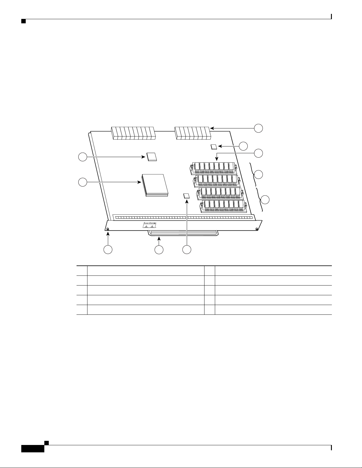
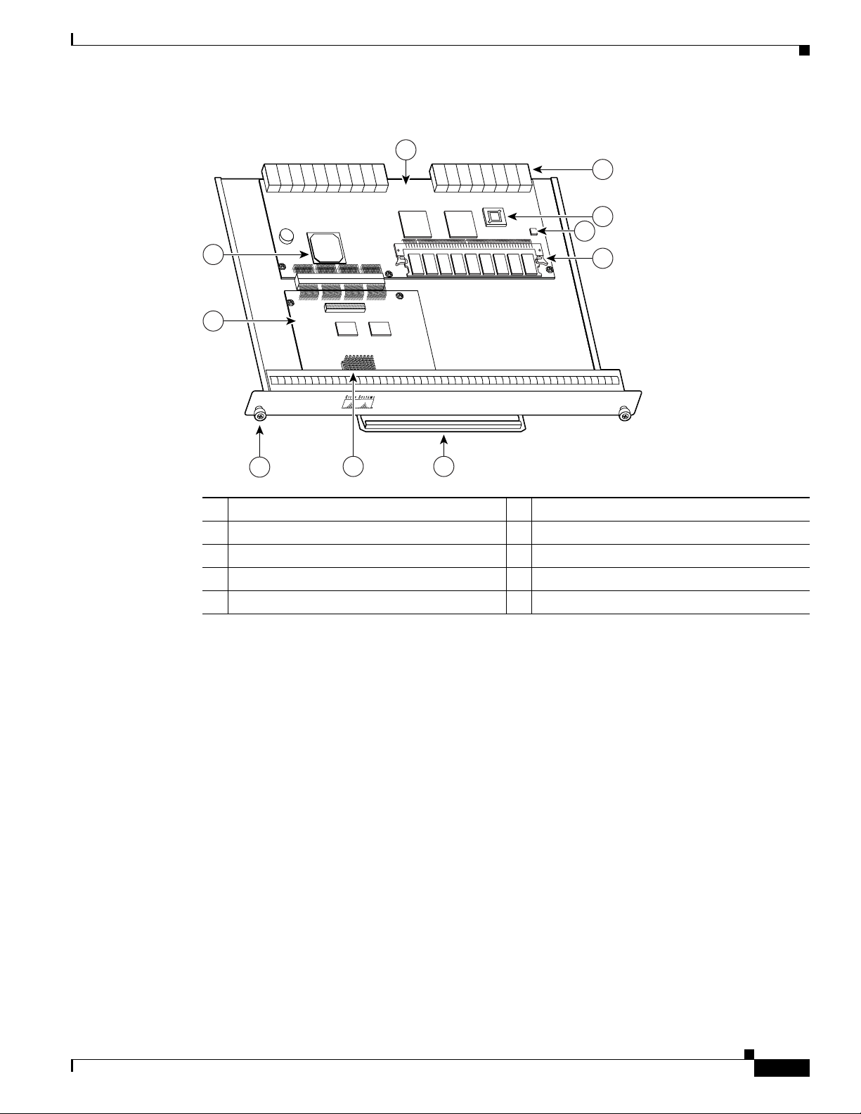
Figure 1-1 NPE-10 0
Chapter 1 NPE-100, NPE-150, and NPE-200 Overview
1 System controller 6 Midplane connectors
2 R4700 microprocessor 7 Temperature sensor
3 Captive installation screw 8 DRAM SIMMs
4 Handle 9 Bank 1
5 Temperature sensor 10 Bank 0
Network Processing Engine and Network Services Engine Installation and Configuration
1-2
OL-4448-12
Page 17
Chapter 1 NPE-100, NPE-150, and NPE-200 Overview
66424
U12
U4
U25
U18
N
ETW
ORK
PR
OC
E
SS
IN
G EN
GIN
E-150
7
10
9
11
4 6
5
3
2
1
8
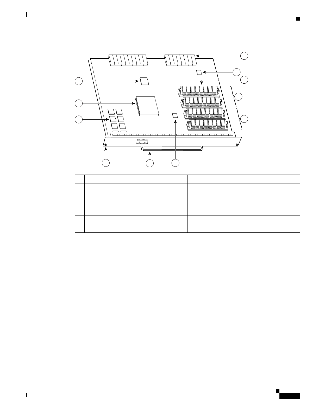
Figure 1-2 NPE-1 50
NPE-100, NPE-150, and NPE-200 Description and Overview
1 System controller 7 Midplane connectors
2 R4700 microprocessor 8 Temperature sensor
3 1-MB SRAM (U700 through U703 and
9 DRAM SIMMs
U800 through U803)
4 Captive installation screw 10 Bank 1
5 Handle 11 Bank 0
6 Temperature sensor
Network Processing Engine and Network Services Engine Installation and Configuration
OL-4448-12
1-3
Page 18
NPE-100, NPE-150, and NPE-200 Description and Overview
66420
U52
U42
U25
U11
N
ETW
OR
K
P
RO
CE
SSIN
G EN
G
IN
E-200
7
11
10
8
12
4 6
5
3
2
1
9
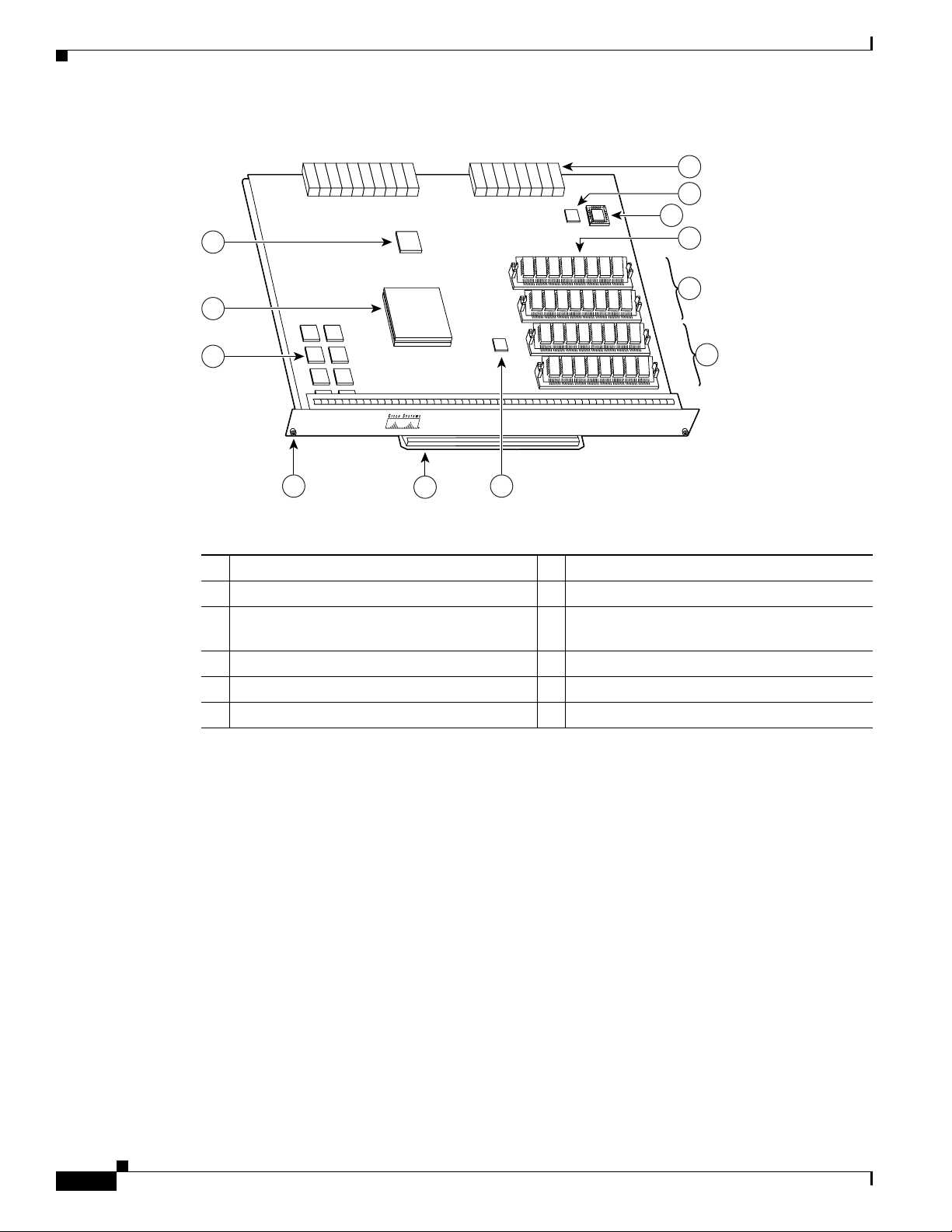
Figure 1-3 NPE-2 00
Chapter 1 NPE-100, NPE-150, and NPE-200 Overview
1 System controller 7 Midplane connectors
2 R5000 microprocessor 8 Temperature sensor
3 4-MB SRAM (U6, U10, U13, U14, U28, U29,
9 Boot ROM U92
U38, and U39)
4 Captive installation screw 10 DRAM SIMMs
5 Handle 11 Bank 1
6 Temperature sensor 12 Bank 0
The NPE-100, NPE-150, and NPE-200 consist of the following components:
• Reduced instruction set computing (RISC) microprocessor
–
The NPE-100 and NPE-150 have an R4700 microprocessor that operates at an internal clock
speed of 150 MHz.
–
The NPE-200 has an R5000 microprocessor that operates at an internal clock speed of
200
MHz.
• System controller
The system controller provides hardware logic to interconnect the processor, DRAM, and the
PCI-based system backplane bus. The NPE-150 and NPE-200 have a system controller that uses
direct memory access (DMA) to transfer data between DRAM and packet SRAM on the network
processing engine.
Network Processing Engine and Network Services Engine Installation and Configuration
1-4
OL-4448-12
Page 19

Chapter 1 NPE-100, NPE-150, and NPE-200 Overview
• Upgradable memory modules
The NPE-100, NPE-150, and NPE-200 use DRAM for storing routing tables, network accounting
applications, packets of information in preparation for process switching, and packet buffering for
SRAM overflow (except in the NPE-100, which contains no packet SRAM). The standard
configuration is 32 MB, with up to 128 MB available through single in-line memory module
(SIMM) upgrades.
• Packet SRAM for storing data packets
–
The NPE-100 does not have packet SRAM.
–
The NPE-150 has 1 MB of SRAM.
–
The NPE-200 has 4 MB of SRAM.
• Cache memory
The NPE-100, NPE-150, and NPE-200 have unified cache SRAM that functions as the secondary
cache for the microprocessor. (The primary cache is within the microprocessor.)
• Two environmental sensors for monitoring the cooling air as it leaves the chassis
• Boot ROM for storing sufficient code for booting the Cisco IOS software on the NPE-200
NPE-100, NPE-150, and NPE-200 Description and Overview
Note The NPE-100 and NPE-150 use the boot ROM on the I/O controller.
System Management Functions
The network processing engines perform the following system management functions:
• Sending and receiving routing protocol updates
• Managing tables, caches, and buffers
• Monitoring interface and environmental status
• Providing Simple Network Management Protocol (SNMP) management through the console and
Telnet interface
• Accounting for and switching of data traffic
• Booting and reloading images
• Managing port adapters (including recognition and initialization during online insertion and
removal)
Terms and Acronyms
• Cache—Memory with fast access and small capacity used to temporarily store recently accessed
data; found either incorporated into the processor or near it.
• DIMM—dual in-line memory module
• DRAM—dynamic random-access memory
OL-4448-12
• Instruction and data cache—Instructions to the processor, and data on which the instructions work.
• Integrated cache—Cache that is built into the processor; sometimes referred to as internal cache.
Cache memory physically located outside the processor is not integrated, and is sometimes referred
to as external cache.
Network Processing Engine and Network Services Engine Installation and Configuration
1-5
Page 20

NPE-100, NPE-150, and NPE-200 Memory Information
• OTP—one time programmable
• Primary, secondary, tertiary cache—Hierarchical cache memory storage based on the proximity of
the cache to the core of the processor. Primary cache is closest to the processor core and has the
fastest access. Secondary cache has slower access than primary cache, but faster access than tertiary
cache.
• RAM—random-access memory
• RISC—reduced instruction set computing
• ROM—read-only memory
• SIMM—single in-line memory module
• SDRAM—synchronous dynamic random-access memory
• SDRAM-fixed—SDRAM of a fixed size or quantity; can be replaced, but not upgraded
• SODIMM—small outline dual in-line memory module
• SRAM—static random-access memory
• Unified cache—Instruction cache and data cache are combined. For example, a processor may have
primary cache with separate instruction and data cache memory, but unified secondary cache.
Chapter 1 NPE-100, NPE-150, and NPE-200 Overview
NPE-100, NPE-150, and NPE-200 Memory Information
To determine the memory configuration of your NPE, use the show version command.
The following example shows an NPE-150 installed in a Cisco 7206 router:
router(boot)# show version
Cisco Internetwork Operating System Software
IOS (tm) 7200 Software (C7200-J-M), Released Version 11.1(17)CA
Copyright (c) 1986-1999 by cisco Systems, Inc.
Compiled Sun 21-Apr-96 04:10
Image text-base:0x60010890, data-base:0x605F0000
(display text omitted)
cisco 7206 (NPE150) processor with 12288K/4096K bytes of memory.
R4700 processor, Implementation 33, Rev 1.0, (Level 2 Cache)
Last reset from power-on
(display text omitted)
Use the following sections for information about memory specifications and configurations for the
NPE-100, NPE-150, and NPE-200.
Note To prevent DRAM errors in the NPE-100, NPE-150, or NPE-200, and to ensure that your system
initializes correctly at startup, DRAM bank 0 (socket U18 and U25, or U11 and U25) must contain no
fewer than two SIMMs of the same type. You may also install two SIMMs of the same type in bank 1
(socket U4 and U12, or U42 and U52); however, bank 0 must always contain the two largest SIMMs.
1-6
Network Processing Engine and Network Services Engine Installation and Configuration
OL-4448-12
Page 21

Chapter 1 NPE-100, NPE-150, and NPE-200 Overview
NPE-100, NPE-150, and NPE-200 Memory Information
NPE-100 Memory Information
Table 1-1 provides information about memory specifications. Tab l e 1-2 provides memory configurations
for the NPE-100.
Ta b l e 1-1 NPE-100 Memory Specifications
Component Location on
Memory Type Size Quantity Description
DRAM 32 to 128 MB 2 to 4 16- or 32-MB SIMMs (based on
maximum DRAM required)
Primary cache — — R4700 processor, internal cache U201
Secondary cache 512 KB 4 R4700 processor, unified, external cache U2, U10, U14, and U26
Ta b l e 1-2 NPE-100 DRAM SIMM Configurations—Configurable Memory Only
the NPE-100 Baord
Bank 0: U18 and U25
Bank 1: U4 and U12
Total DRAM
32 MB U18 and U25 2 16-MB SIMMs
64 MB U18 and U25 2 32-MB SIMMs U4 and U12 — MEM-NPE-64MB
128 MB U18 and U25 2 32-MB SIMMs U4 and U12 2 32-MB SIMMs MEM-NPE-128MB
1. Refer to the Cisco AS5800 Universal Access Server documentation listed in the “Related Documentation” section on page iii for Cisco AS5800
Universal Access Server DRAM options.
2. These products are also available as DRAM upgrades. For example, to upgrade a network processing engine from 32 MB to 64 MB of DRAM, order
Product Number MEM-NPE-64MB=.
1
Bank 0 Quantity - Bank 0 Bank 1 Quantity - Bank 1 Product Number
2
U4 and U12 — MEM-NPE-32MB
2
2
2
NPE-150 Memory Information
Table 1-3 provides information about memory specifications. Tab l e 1-4 provides memory configurations
for the NPE-150.
Ta b l e 1-3 NPE-150 Memory Specifications
Component Location on the
Memory Type Size Quantity Description
DRAM 32 to 128 MB 2 to 4 16- or 32-MB SIMMs (based on maximum
DRAM required)
SRAM 1 MB 8 8 chips, each being 128K x 9 bits wide U700 through U703
Primary cache — — R4700 processor, internal cache U201
Secondary cache 512 MB 4 R4700 processor, unified, external cache U2, U10, U14, and U26
NPE-150 Board
Bank 0: U18 and U2
Bank 1: U4 and U12
U800 through U803
OL-4448-12
Network Processing Engine and Network Services Engine Installation and Configuration
1-7
Page 22

Chapter 1 NPE-100, NPE-150, and NPE-200 Overview
NPE-100, NPE-150, and NPE-200 Memory Information
Ta b l e 1-4 NPE-150 DRAM SIMM Configurations—Configurable Memory Only
Total DRAM
1
Bank 0 Quantity - Bank 0 Bank 1 Quantity - Bank 1 Product Number
32 MB U18 and U25 2 16-MB SIMMs U4 and U12 — MEM-NPE-32 MB
64 MB U18 and U25 2 32-MB SIMMs U4 and U12 — MEM-NPE-64MB
128 MB U18 and U25 2 32-MB SIMMs U4 and U12 2 32-MB SIMMs MEM-NPE-128MB
1. Refer to the Cisco AS5800 Universal Access Server documentation listed in the “Related Documentation” section on page iii for Cisco AS5800
Universal Access Server DRAM options.
2. These products are also available as DRAM upgrades. For example, to upgrade a network processing engine from 32 MB to 64 MB of DRAM, order
Product Number MEM-NPE-64MB=.
NPE-200 Memory Information
Table 1-5 provides information about memory specifications. Tab l e 1-6 provides memory configurations
for the NPE-200.
Ta b l e 1-5 NPE-200 Memory Specifications
Component Location on the
Memory Type Size Quantity Description
DRAM 32 to 128 MB 2 to 4 16- or 32-MB SIMMs (based on
maximum DRAM required)
SRAM 4 MB 8 8 chips, each being 512K x 8 bits wide U6, U10, U13, U14, U28, U29,
Boot ROM 256 KB 1 EPROM for the ROM monitor
programs
Primary cache — — R5000 processor, internal cache U44
Secondary cache 512 KB 4 R5000 processor, unified, external
cache
NPE-200 Board
Bank 0: U11 and U25
Bank 1: U42 and U52
U38, and U39
U92
U16, U9, U109, and U107
2
2
2
Ta b l e 1-6 NPE-200 DRAM SIMM Configurations—Configurable Memory Only
Total DRAM
32 MB U11 and U25 2 16-MB SIMMs U42 and U52 — MEM-NPE-32MB
64 MB U11 and U25 2 32-MB SIMMs U42 and U52 — MEM-NPE-64MB
128 MB U11 and U25 2 32-MB SIMMs U42 and U52 2 32-MB SIMMs MEM-NPE-128MB
1. Refer to the Cisco AS5800 Universal Access Server documentation listed in the “Related Documentation” section on page iii for Cisco AS5800
Universal Access Server DRAM options.
2. These products are also available as DRAM upgrades. For example, to upgrade a network processing engine from 32 MB to 64 MB of DRAM, order
Product Number MEM-NPE-64MB=.
1-8
1
Bank 0 Quantity - Bank 0 Bank 1 Quantity - Bank 1 Product Number
Network Processing Engine and Network Services Engine Installation and Configuration
2
2
2
OL-4448-12
Page 23

NPE-175 and NPE-225 Overview
This chapter describes the network processing engine (NPE) models NPE-175 and NPE-225 and
contains the following sections:
• Supported Platforms, page 2-1
• Software Requirements, page 2-1
• NPE-175 and NPE-225 Description and Overview, page 2-1
• NPE-175 and NPE-225 Memory Information, page 2-5
Supported Platforms
The following NPEs support the Cisco 7200 series routers and Cisco 7200 VXR routers:
• NPE-175
• NPE-225
The following NPEs support the Cisco uBR7246VXR universal broadband router, Cisco uBR7246, and
Cisco
uBR7223 universal broadband routers:
CHAP T ER
2
• NPE-175
• NPE-225
Software Requirements
For minimum software release information, see the “Software Requirements” section on page 8-4.
NPE-175 and NPE-225 Description and Overview
This section contains information about the network processing engine components and the system
management functions. The network processing engine maintains and executes the system management
functions for the Cisco 7200 series and Cisco
memory and environmental monitoring functions with the I/O controller.
Network Processing Engine and Network Services Engine Installation and Configuration
OL-4448-12
uBR7200 series routers. The NPE also shares the system
2-1
Page 24
NPE-175 and NPE-225 Description and Overview
66416
N
ET
W
O
R
K
PRO
C
E
SSIN
G
E
NG
IN
E-150
1
7
4
65
2
3
8
9
10
Components
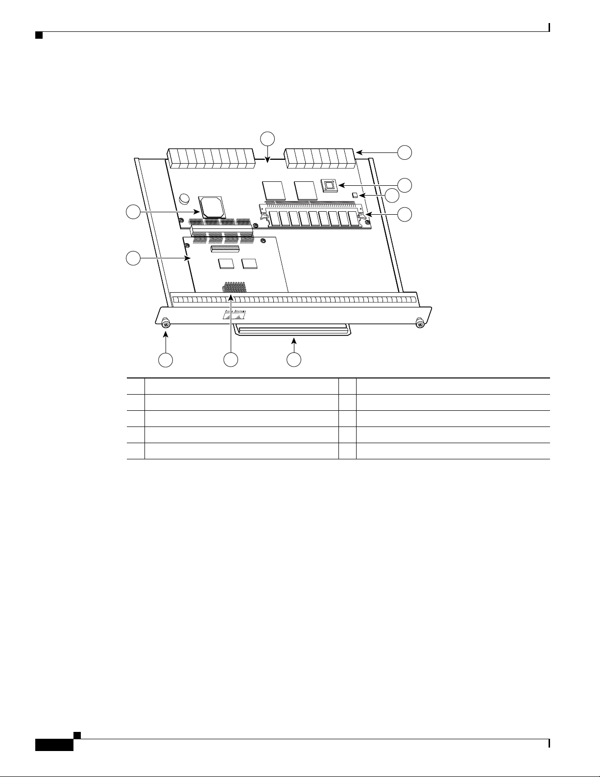
Figure 2-1 NPE-175
Chapter 2 NPE-175 and NPE-225 Overview
1 Network controller board 6 Handle
2 System controller 7 Midplane connectors
3 Processor engine board 8 Boot ROM (U1)
4 Captive installation screw 9 Temperature sensor
5 RM5270 microprocessor 10 SDRAM DIMM (U15)
Network Processing Engine and Network Services Engine Installation and Configuration
2-2
OL-4448-12
Page 25
Chapter 2 NPE-175 and NPE-225 Overview
66417
N
ET
W
O
R
K
PR
O
C
ESS
IN
G
EN
G
IN
E-200
1
7
4
65
2
3
8
9
10
Figure 2-2 NPE-225
NPE-175 and NPE-225 Description and Overview
1 Network controller board 6 Handle
2 System controller 7 Midplane connectors
3 Processor engine board 8 Boot ROM (U1)
4 Captive installation screw 9 Temperature sensor
5 RM5271 microprocessor 10 SDRAM DIMM (U15)
The NPE-175 and NPE-225 consist of the following components:
• Reduced instruction set computing (RISC) microprocessor
–
The NPE-175 has an RM5270 microprocessor that operates at an internal clock speed of
200
MHz.
–
The NPE-225 has an RM5271 microprocessor that operates at an internal clock speed of
262
MHz.
• System controller
The system controller provides hardware logic to interconnect the processor, DRAM, and the
PCI-based system backplane bus. The NPE-175 and NPE-225 have one system controller that
provides processor access to the two midplane and single I/O controller peripheral component
interconnect (PCI) buses. The system controller also allows port adapters—on either of the two
midplane PCI buses—access to SDRAM.
• Upgradable memory modules
The NPE-175 and NPE-225 use SDRAM for providing code, data, and packet storage.
• Cache memory
The NPE-175 and NPE-225 have unified cache SRAM that functions as the secondary cache for the
microprocessor. (The primary cache is within the microprocessor.)
OL-4448-12
• Two environmental sensors for monitoring the cooling air as it leaves the chassis
Network Processing Engine and Network Services Engine Installation and Configuration
2-3
Page 26

NPE-175 and NPE-225 Description and Overview
• Boot ROM for storing sufficient code for booting the Cisco IOS software; the NPE-175 and
NPE-225 have boot ROM
Note Neither the NPE-175 nor the NPE-225 has packet SRAM.
System Management Functions
The network processing engines perform the following system management functions:
• Sending and receiving routing protocol updates
• Managing tables, caches, and buffers
• Monitoring interface and environmental status
• Providing Simple Network Management Protocol (SNMP) management through the console and
Telnet interface
• Accounting for and switching of data traffic
• Booting and reloading images
• Managing port adapters (including recognition and initialization during online insertion and
removal)
Chapter 2 NPE-175 and NPE-225 Overview
Terms and Acronyms
• Cache—Memory with fast access and small capacity used to temporarily store recently accessed
data; found either incorporated into the processor or near it.
• DIMM—dual in-line memory module
• DRAM—dynamic random-access memory
• Instruction and data cache—Instructions to the processor, and data on which the instructions work.
• Integrated cache—Cache that is built into the processor; sometimes referred to as internal cache.
Cache memory physically located outside the processor is not integrated, and is sometimes referred
to as external cache.
• OTP—one time programmable
• Primary, secondary, tertiary cache—Hierarchical cache memory storage based on the proximity of
the cache to the core of the processor. Primary cache is closest to the processor core and has the
fastest access. Secondary cache has slower access than primary cache, but faster access than tertiary
cache.
• RAM—random-access memory
• RISC—reduced instruction set computing
• ROM—read-only memory
• SIMM—single in-line memory module
• SDRAM—synchronous dynamic random-access memory
2-4
• SDRAM-fixed—SDRAM of a fixed size or quantity; can be replaced, but not upgraded
• SODIMM—small outline dual in-line memory module
Network Processing Engine and Network Services Engine Installation and Configuration
OL-4448-12
Page 27

Chapter 2 NPE-175 and NPE-225 Overview
• SRAM—static random-access memory
• Unified cache— Instruction cache and data cache are combined. For example, a processor may have
primary cache with separate instruction and data cache memory, but unified secondary cache.
NPE-175 and NPE-225 Memory Information
To determine the memory configuration of your NPE, use the show version command.
The following example shows an NPE-225 installed in a Cisco 7206VXR router:
router(boot)# show version
Cisco Internetwork Operating System Software
IOS (tm) 7200 Software (C7200-BOOT-M), Released Version 12.0(19990124:222541)
[biff-nightly 115]
Copyright (c) 1986-1999 by cisco Systems, Inc.
Compiled Mon 15-Feb-99 21:50 by biff
Image text-base:0x600088F8, data-base:0x6064C000
(display text omitted)
cisco 7206VXR (NPE225) processor with 57344K/8192K bytes of memory.
R527x CPU at 262Mhz, Implementation 40, Rev 10.0, 2048KB L2 Cache
6 slot VXR midplane, Version 2.0
NPE-175 and NPE-225 Memory Information
(display text omitted)
Table 2-1 provides memory specifications, Tab l e 2-2 provides memory configurations for the NPE-175,
and Table 2-3 provides memory configurations for the NPE-225.
Ta b l e 2-1 NPE-175 and NPE-225 Memory Specifications
Memory Type Size Quantity Description
SDRAM 64 or 128 MB 1 configurable
DIMM U15
bank with 1
SDRAM slot
Boot ROM 512 KB 1 OTP ROM for the ROM monitor
program
Primary cache 16 KB (instruction),
16 KB (data)
32 KB (instruction),
32 KB (data)
Secondary cache 2 MB 4 x 256 x 18 bits =
— RM5270 processor, primary internal
cache
— RM5271 processor, primary internal
cache
RM527x processor, unified external
64 bit plus 4 parity
cache
bits
1. Located on the processor engine board.
Component
Location on the
NPE-175 and
NPE-225 Board
U1
U4
U4
U5, U6, U7, U8
1
OL-4448-12
Network Processing Engine and Network Services Engine Installation and Configuration
2-5
Page 28

Chapter 2 NPE-175 and NPE-225 Overview
NPE-175 and NPE-225 Memory Information
Ta b l e 2-2 NPE-175 SDRAM DIMM Configurations—Configurable Memory Only
Total SDRAM Bank Quantity Product Number
64 MB U15 1 64-MB DIMM MEM-SD-NPE-64MB
128 MB U15 1 128-MB DIMM MEM-SD-NPE-128MB
Ta b l e 2-3 NPE-225 SDRAM DIMM Configurations—Configurable Memory Only
Total SDRAM Bank Quantity Product Number
64 MB U15 1 64-MB DIMM MEM-SD-NPE-64MB
128 MB U15 1 128-MB DIMM MEM-SD-NPE-128MB
256 MB U15 1 256-MB DIMM MEM-SD-NSE-256MB
2-6
Network Processing Engine and Network Services Engine Installation and Configuration
OL-4448-12
Page 29

NPE-300 and NPE-400 Overview
This chapter describes the network processing engine (NPE) models NPE-300 and NPE-400 and
contains the following sections:
• Supported Platforms, page 3-1
• Software Requirements, page 3-1
• NPE-300 and NPE-400 Description and Overview, page 3-2
• NPE-300 and NPE-400 Memory Information, page 3-5
Supported Platforms
The following NPEs support the Cisco 7200 VXR routers:
• NPE-300
• NPE-400
The following NPEs support the Cisco uBR7246VXR universal broadband router:
CHAP T ER
3
• NPE-300
• NPE-400
The following NPEs support the Cisco 7206VXR as a router shelf in the Cisco AS5800 Universal Access
Router:
• NPE-300
• NPE-400
These NPEs are keyed to prevent insertion in the Cisco 7200 series routers (7202, 7204, 7206).
Software Requirements
For minimum software release information, see the “Software Requirements” section on page 8-4.
Network Processing Engine and Network Services Engine Installation and Configuration
OL-4448-12
3-1
Page 30
Chapter 3 NPE-300 and NPE-400 Overview
66410
N
E
T
W
O
R
K
P
R
O
C
ES
S
IN
G
E
N
G
IN
E
-30
0
11
2
1
12
13
3
4
5
14
15
16
109876
NPE-300 and NPE-400 Description and Overview
NPE-300 and NPE-400 Description and Overview
This section contains information about the network processing engine components and the system
management functions. The network processing engine maintains and executes the system management
functions for the routers. It also shares the system memory and environmental monitoring functions with
the I/O controller.
Components
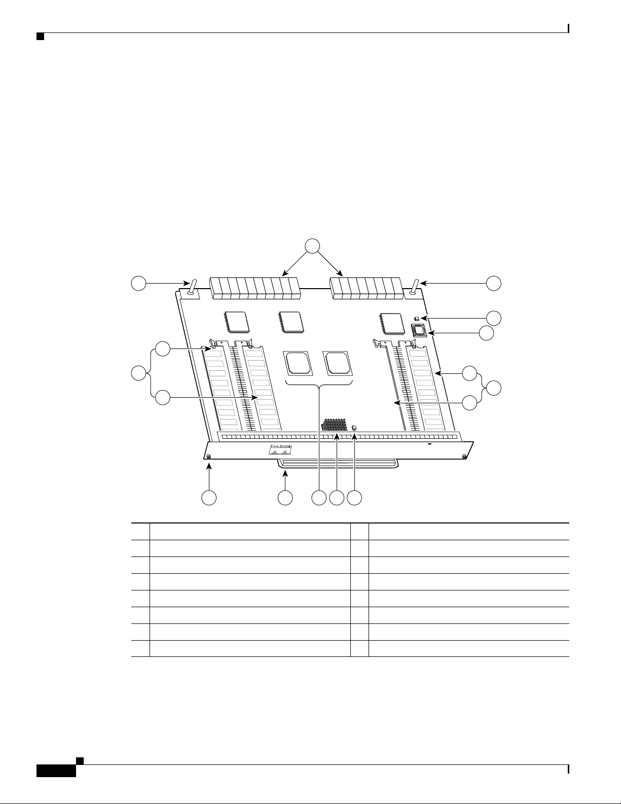
Figure 3-1 NPE-300
1 Midplane connectors 9 RM7000 microprocessor
2 Keying post 10 Temperature sensor (U42)
3 DIMM 3 (U44) 11 Keying post
4 Bank 1 (user configurable) 12 Temperature sensor (U41)
5 DIMM 2 (U45) 13 Boot ROM (U1)
6 Captive installation screw 14 DIMM 0 (U16)
7 Handle 15 Bank 0 (fixed)
8 System controllers 16 U15 (never populated)
Network Processing Engine and Network Services Engine Installation and Configuration
3-2
OL-4448-12
Page 31

Chapter 3 NPE-300 and NPE-400 Overview
NE
TW
O
R
K
PRO
C
ESSIN
G
E
NG
IN
E-400
NE
TW
O
R
K
PRO
C
ESSIN
G
E
NG
IN
E-400
66411
9
10
11
1
7
8
65
2
3
4
Figure 3-2 NPE-400
NPE-300 and NPE-400 Description and Overview
1 Temperature sensor (U31) 7 Midplane connectors
2 Keying post 8 Boot ROM (U7)
3 RM7000 microprocessor 9 Temperature sensor (U6)
4 System controller 10 SODIMM (J1)
5 Captive installation screw 11 Standoff and screw
6 Handle
The network processing engines consist of the following components:
• Reduced instruction set computing (RISC) microprocessor
–
The NPE-300 uses an RM7000 microprocessor that operates at an internal clock speed of
262
MHz.
–
The NPE-400 uses an RM7000 microprocessor that operates at an internal clock speed of
350
MHz.
• System controller
The system controller provides hardware logic to interconnect the processor, DRAM, and the
PCI-based system backplane bus.
–
The NPE-300 has two system controllers that provide processor access to the midplane and
single I/O controller PCI buses. The system controllers also allow port adapters access to
SDRAM using any of the three PCI buses.
–
The NPE-400 has a single system controller that provides system access.
OL-4448-12
Network Processing Engine and Network Services Engine Installation and Configuration
3-3
Page 32

NPE-300 and NPE-400 Description and Overview
• Upgradable memory modules
The NPE-300 and NPE-400 use SDRAM for storing all packets received or sent from network
interfaces. The SDRAM also stores routing tables and network accounting applications.
–
On the NPE-300, two independent SDRAM memory arrays in the system allow concurrent
access by port
–
On the NPE-400, one memory array is shared by port adapters and the processor.
• Cache memory
The NPE-300 and NPE-400 have cache SRAM that functions as the tertiary cache for the
microprocessor.
• Two environmental sensors for monitoring the cooling air as it leaves the chassis for both the
NPE-300 and NPE-400
• Boot ROM for storing sufficient code for booting the Cisco IOS software
Note The NPE-300 and the NPE-400 do not have packet SRAM.
Chapter 3 NPE-300 and NPE-400 Overview
adapters and the processor; however, only one is upgradable.
System Management Functions
The network processing engines perform the following system management functions:
• Sending and receiving routing protocol updates
• Managing tables, caches, and buffers
• Monitoring interface and environmental status
• Providing Simple Network Management Protocol (SNMP) management through the console and
Telnet interface
• Accounting for and switching of data traffic
• Booting and reloading images
• Managing port adapters (including recognition and initialization during online insertion and
removal)
Terms and Acronyms
• Cache—Memory with fast access and small capacity used to temporarily store recently accessed
data; found either incorporated into the processor or near it.
• DIMM—dual in-line memory module
• DRAM—dynamic random-access memory
• Instruction and data cache—Instructions to the processor, and data on which the instructions work.
• Integrated cache—Cache that is built into the processor; sometimes referred to as internal cache.
Cache memory physically located outside the processor is not integrated, and is sometimes referred
to as external cache.
3-4
• OTP—one time programmable
Network Processing Engine and Network Services Engine Installation and Configuration
OL-4448-12
Page 33

Chapter 3 NPE-300 and NPE-400 Overview
• Primary, secondary, tertiary cache—Hierarchical cache memory storage based on the proximity of
the cache to the core of the processor. Primary cache is closest to the processor core and has the
fastest access. Secondary cache has slower access than primary cache, but faster access than tertiary
cache.
• RAM—random-access memory
• RISC—reduced instruction set computing
• ROM—read-only memory
• SIMM—single in-line memory module
• SDRAM—synchronous dynamic random-access memory
• SDRAM-fixed—SDRAM of a fixed size or quantity; can be replaced, but not upgraded
• SODIMM—small outline dual in-line memory module
• SRAM—static random-access memory
• Unified cache—Instruction cache and data cache are combined. For example, a processor may have
primary cache with separate instruction and data cache memory, but unified secondary cache.
NPE-300 and NPE-400 Memory Information
NPE-300 and NPE-400 Memory Information
To determine the memory configuration of your NPE-300, use the show version command.
The following example of the show version command shows an NPE-300 installed in a Cisco 7206VXR
router:
Router# show version
Cisco Internetwork Operating System Software
IOS (tm) 7200 Software (C7200-JS-M), Released Version 12.0(19980705:021501)
Copyright (c) 1986-1998 by cisco Systems, Inc.
Compiled Tue 25-Aug-98 04:01 by biff
Image text-base: 0x600088C4, data-base: 0x60FA6000
(display text omitted)
cisco 7206VXR (NPE300) processor with 44x1024K/20480K bytes of memory.
R7000 CPU at 262Mhz, Implementation 39, Rev 1.0, 265KB L2, 2048KB L3 Cache
Six slot VXR midplane, Version 2.255
(display text omitted)
The following example of the show version command shows an NPE-400 installed in a Cisco 7206VXR
router:
Router# show version
Cisco Internetwork Operating System Software
IOS (tm) 7200 Software (C7200-P-M), Released Version 12.1(20000622:181759)
Copyright (c) 1986-2000 by cisco Systems, Inc.
Compiled Thu 22-Jun-00 11:18 by BIFF
Image text-base: 0x60008950, data-base: 0x60BD8000
(display text omitted)
OL-4448-12
Network Processing Engine and Network Services Engine Installation and Configuration
3-5
Page 34

Chapter 3 NPE-300 and NPE-400 Overview
NPE-300 and NPE-400 Memory Information
cisco 7206VXR (NPE400) processor (revision 0xFF) with 122880K/8192K bytes
of memory.
Processor board ID 8771013
R7000 CPU at 350Mhz, Implementation 39, Rev 2.1, 256KB L2, 4096KB L3 Cache
6 slot VXR midplane, Version 2.1
(display text omitted)
Table 3-1 provides memory specifications, and Tabl e 3-2 provides user replaceable memory
configurations for the NPE-300. Table 3-3 provides memory specifications, and Tabl e 3-4 provides
memory configurations for the NPE-400.
Ta b l e 3-1 NPE-300 Memory Specifications
Component Location
Memory Type Size Quantity Description
SDRAM-configurable 32 to 256 MB 1 configurable
bank with
2
SDRAM slots
32-, 64-, or 128-MB DIMMs (based
on maximum SDRAM required)
Boot ROM 512 KB 1 OTP ROM for the ROM monitor
program
SDRAM-fixed 32 MB 1 32-MB DIMM Bank 02: U16
Primary cache 16 KB
— RM7000 processor, integrated cache U49
(instruction),
16
KB (data)
Secondary cache 256 KB
(fixed)
— RM7000 processor, unified, internal
cache
Tertiary cache 2 MB (fixed) — RM7000 processor, external cache U7, U8, U9, U10, U17
1. Located on the processor engine board.
2. Socket U15 is never populated, although it is part of bank 0.
on the NPE-300 Board
Bank 1: U45 and U44
1
U1
U49
Ta b l e 3-2 NPE-300 SDRAM DIMM Configurations—Configurable Memory Only
Total SDRAM
32 MB4 +
1
2
Bank 1
Quantity Product Number
U45 (DIMM slot 2 only) 1 32-MB DIMM MEM-SD-NPE-32MB
32 MB
32MB4 +
64 MB
Network Processing Engine and Network Services Engine Installation and Configuration
U45 and U44
or
U45
2 32-MB DIMMs or
1 64-MB DIMM
3-6
3
MEM-SD-NPE-32MB
MEM-SD-NPE-64MB
OL-4448-12
Page 35

Chapter 3 NPE-300 and NPE-400 Overview
NPE-300 and NPE-400 Memory Information
Table 3-2 NPE-300 SDRAM DIMM Configurations—Configurable Memory Only (continued)
Total SDRAM
32 MB4 +
128 MB
32 MB4 +
1
2
Bank 1
U45 and U44
or
U45
Quantity Product Number
2 64-MB DIMMs or
1 128-MB DIMM
MEM-SD-NPE-64MB
MEM-SD-NPE-128MB
3
U45 and U44 2 128-MB DIMMs MEM-SD-NPE-256MB
256 MB
1. Refer to the Cisco AS5800 Universal Access Server documentation listed in the “Related Documentation” section on page iii for Cisco AS5800
Universal Access Server SDRAM options.
2. There are two user-upgradable SDRAM slots in bank 1. (Bank 0 is used exclusively for packet memory and is set at a fixed configuration of 32 MB in
the factory.)
3. These products are also available as SDRAM upgrades. To order an upgrade, add an equal sign (=) after the product number, for example,
MEM-SD-NPE-128MB=.
4. This 32 MB is fixed memory in SDRAM bank 0, socket U16. Socket U15 is never populated.
Ta b l e 3-3 NPE-400 Memory Specifications
Component
Memory Type Size Quantity Description
Location on
NPE-400 Board
the
SDRAM-configurable 128, 256, or 512 MB 1 128-, 256- or 512-MB SODIMM J1
Boot ROM 512 KB 1 OTP ROM for the ROM monitor program U7
Primary cache 16 KB (instruction),
16
KB (data)
— RM7000 processor, integrated cache U38
Secondary cache 256 KB (fixed) — RM7000 processor, unified, internal cache U38
Tertiary cache 4 MB (fixed) — RM7000 processor, external cache U2, U26, U27,
U28, U37
Ta b l e 3-4 NPE-400 Memory Configuration
Total SDRAM Bank 1 Quantity Product Number
128 MB J1 1 128-MB SODIMM MEM-NPE-400-128MB
256 MB J1 1 256-MB SODIMM MEM-NPE-400-256MB
512 MB J1 1 512-MB SODIMM MEM-NPE-400-512MB
Network Processing Engine and Network Services Engine Installation and Configuration
OL-4448-12
3-7
Page 36

NPE-300 and NPE-400 Memory Information
Chapter 3 NPE-300 and NPE-400 Overview
3-8
Network Processing Engine and Network Services Engine Installation and Configuration
OL-4448-12
Page 37

NSE-1 Overview
This chapter describes the network services engine (NSE-1) and contains the following sections:
• Supported Platforms, page 4-1
• Software Requirements, page 4-1
• NSE-1 Description and Overview, page 4-1
• NSE-1 Memory Information, page 4-4
For NSE-1 configuration and PXF troubleshooting information including NSE-1-specific show and
debug commands, see
Supported Platforms
The NSE-1 is supported only in the Cisco 7200 VXR routers. The NSE-1 is not supported in the
Cisco
uBR7200 VXR series routers.
CHAP T ER
Chapter 10, “Configuration Tasks and Troubleshooting Information.”
4
Software Requirements
For minimum software release information, see the “Software Requirements” section on page 8-4.
NSE-1 Description and Overview
This section contains information about the network services engine components and the system
management functions. The network services engine maintains and executes the system management
functions for the Cisco
environmental monitoring functions with the I/O controller. Its performance is greater than that of the
network processing engines because of the Parallel eXpress Forwarding (PXF) processor. The PXF
processor works with the routing processor to provide accelerated packet switching, as well as
accelerated IP Layer
The NSE-1 consists of two modular boards: the processor engine board and the network controller board.
It is keyed so that it can be used only in the Cisco
OL-4448-12
7200 VXR routers. The NSE-1 also shares the system memory and
3 feature processing.
Network Processing Engine and Network Services Engine Installation and Configuration
7200 VXR routers.
4-1
Page 38

NSE-1 Description and Overview
66418
N
E
T
W
O
R
K
PR
O
C
ES
SIN
G
EN
G
IN
E
-200
1
8
5
7
6
3
2
4
9
10
11
12
13
Note The NSE-1 is not supported in the Cisco uBR7200 VXR series routers, even though it is physically
Components
Chapter 4 NSE-1 Overview
capable of being inserted into the routers.
Figure 4-1 NSE-1
1 Network controller board 8 Midplane connectors
2 Keying post 9 Boot ROM (U1)
3 System controller 10 Temperature sensor
4 Processor engine board 11 SDRAM DIMM (U15)
5 Captive installation screw 12 Parallel eXpress Forwarding (PXF) processor
6 RM7000 microprocessor 13 Temperature sensor
7 Handle
The NSE-1 consists of the following components:
• Reduced instruction set computing (RISC) microprocessor
The NSE-1 uses an RM7000 microprocessor that operates at an internal clock speed of 262 MHz.
• Parallel eXpress Forwarding processor
The Parallel eXpress Forwarding (PXF) processor enables parallel IP multipacket processing
functions, working with the routing processor to provide accelerated packet switching, as well as
accelerated IP Layer 3 feature processing.
Network Processing Engine and Network Services Engine Installation and Configuration
4-2
OL-4448-12
Page 39

Chapter 4 NSE-1 Overview
• System controller
• Upgradable memory modules
• Cache memory
• Two environmental sensors for monitoring the cooling air as it leaves the chassis
• Boot ROM for storing sufficient code for booting the Cisco IOS software
NSE-1 Description and Overview
The system controller provides hardware logic to interconnect the processor, DRAM, and the
PCI-based system backplane bus. The NSE-1 has one system controller that provides processor
access to the two midplane and single I/O controller PCI buses. The system controller also allows
port adapters—on either of the two midplane PCI buses—access to SDRAM.
The NSE-1 uses SDRAM for providing code, data, and packet storage.
The NSE-1 has three levels of cache: primary and secondary cache that are internal to the
microprocessor with secondary unified cache for data and instruction, and tertiary, 2-MB external
cache.
Note The NSE-1 does not have packet SRAM.
System Management Functions
The NSE-1 performs the following system management functions:
• Sending and receiving routing protocol updates
• Managing tables, caches, and buffers
• Monitoring interface and environmental status
• Providing Simple Network Management Protocol (SNMP) management through the console and
Telnet interface
• Accounting for and switching of data traffic
• Booting and reloading images
• Managing port adapters (including recognition and initialization during online insertion and
removal)
Terms and Acronyms
• Cache—Memory with fast access and small capacity used to temporarily store recently accessed
data; found either incorporated into the processor or near it.
• DIMM—dual in-line memory module
• DRAM—dynamic random-access memory
• Instruction and data cache—Instructions to the processor, and data on which the instructions work.
• Integrated cache—Cache that is built into the processor; sometimes referred to as internal cache.
Cache memory physically located outside the processor is not integrated, and is sometimes referred
to as external cache.
OL-4448-12
• OTP—one time programmable
Network Processing Engine and Network Services Engine Installation and Configuration
4-3
Page 40

NSE-1 Memory Information
• Primary, secondary, tertiary cache—Hierarchical cache memory storage based on the proximity of
• RAM—random-access memory
• RISC—reduced instruction set computing
• ROM—read-only memory
• SIMM—single in-line memory module
• SDRAM—synchronous dynamic random-access memory
• SDRAM-fixed—SDRAM of a fixed size or quantity; can be replaced, but not upgraded
• SODIMM—small outline dual in-line memory module
• SRAM—static random-access memory
• Unified cache—Instruction cache and data cache are combined. For example, a processor may have
Chapter 4 NSE-1 Overview
the cache to the core of the processor. Primary cache is closest to the processor core and has the
fastest access. Secondary cache has slower access than primary cache, but faster access than tertiary
cache.
primary cache with separate instruction and data cache memory, but unified secondary cache.
NSE-1 Memory Information
To determine the memory configuration of your NSE-1, use the show version command.
The following example shows an NSE-1 installed in a Cisco 7206VXR router:
Router# show version
Cisco Internetwork Operating System Software
IOS (tm) 7200 Software (C7200-P-M), Released Version 12.0
Copyright (c) 1986-1999 by cisco Systems, Inc.
Compiled Wed 22-Dec-99 08:37 by
Image text-base:0x60008900, data-base:0x60B58000
(display text omitted)
cisco 7206VXR NSE-1 processor with 57344K/8192K bytes of memory.
R7000 CPU at 262Mhz, Implementation 39, Rev 1.0, 256KB L2 Cache
6 slot VXR midplane, Version 2.0
(display text omitted)
Table 4-1 provides memory specifications and Tabl e 4-2 provides user replaceable memory
configuration information for the NSE-1.
Ta b l e 4-1 NSE-1 Memory Specifications
Component Location
Memory Type Size Quantity Description
SDRAM 128 MB or 256 MB 1 128-MB or 256-MB DIMMs U15
Boot ROM 512 KB 1 OTP1 ROM for the ROM monitor program U1
Primary cache 16 KB (instruction),
16
KB (data)
— RM7000 processor, internal cache U22
on the NSE-1 Board
4-4
Network Processing Engine and Network Services Engine Installation and Configuration
OL-4448-12
Page 41

Chapter 4 NSE-1 Overview
NSE-1 Memory Information
Table 4-1 NSE-1 Memory Specifications (continued)
Component Location
Memory Type Size Quantity Description
Secondary cache 256 KB — RM7000 processor, internal, unified cache U22
Tertiary cache 2 MB (fixed) — RM7000 processor, external cache2 U7, U9, U12, U14,
1. OTP = one time programmable
2. Located on the processor engine board.
Ta b l e 4-2 NSE-1 SDRAM DIMM Configurations—Configurable Memory Only
Total SDRAM SDRAM Bank Quantity Product Number
128 MB U15 1 128-MB DIMM MEM-SD-NPE-128MB
256 MB U15 1 256-MB DIMM MEM-SD-NSE-256MB
on the NSE-1 Board
U17
OL-4448-12
Network Processing Engine and Network Services Engine Installation and Configuration
4-5
Page 42

NSE-1 Memory Information
Chapter 4 NSE-1 Overview
4-6
Network Processing Engine and Network Services Engine Installation and Configuration
OL-4448-12
Page 43

CHAP T ER
5
NPE-G1 Overview
This chapter describes the NPE-G1 and contains the following sections:
• Supported Platforms, page 5-1
• Software Requirements, page 5-1
• NPE-G1 Description and Overview, page 5-2
• NPE-G1 Memory Information, page 5-9
• Connection Equipment and Specifications, page 5-10
• Fiber Optic Cleaning Information, page 5-20
Caution You must copy and save your running configuration file to a CompactFlash Disk, PC Card, or TFTP
server before you install the NPE-G1. For instructions on copying and saving your configuration file, see
the
“Copying the Configuration File” section on page 7-4 in Chapter 7, “NPE-G1 and NPE-G2
Installation and Configuration Information.”
For general preparation for installation instructions, see Chapter 8, “Preparation for Installation.” For
installation and configuration instructions specific to the NPE-G1, see Chapter 7, “NPE-G1 and NPE-G2
Installation and Configuration Information.”
Supported Platforms
The NPE-G1 is supported only in the Cisco 7200 VXR routers, the Cisco uBR7246VXR universal
broadband router, and the Cisco uBR7225VXR universal broadband router. For the Cisco
routers, order Part Number NPE-G1 or NPE-G1=. For the Cisco
uBR7225VXR routers, order Part Number UBR7200-NPE-G1 or UBR7200-NPE-G1=.
Note Unless otherwise indicated, all references to NPE-G1 in this document also refer to UBR7200-NPE-G1.
Software Requirements
For minimum software release information, see the “Software Requirements” section on page 8-4.
Network Processing Engine and Network Services Engine Installation and Configuration
OL-4448-12
7200 VXR
uBR7246VXR and Cisco
5-1
Page 44

NPE-G1 Description and Overview
NPE-G1 Description and Overview
This section contains information about the NPE-G1 components and the system management functions.
The NPE-G1 is the first net
processing engine for the Cisco 7200 VXR routers and Cisco uBR7200 series routers to provide the
functionality of both a network processing engine and I/O controller. If used without an I/O controller,
an I/O controller blank panel must be in place.
While its design provides I/O controller functionality, it can also work with any I/O controller supported
in the Cisco 7200 VXR routers and Cisco
I/O controller, provides the bootflash and NVRAM that the Cisco
Note An I/O controller can be used with the NPE-G1, but an I/O controller is not necessary for system
functionality. Installing an I/O controller in a chassis with the NPE-G1 activates the console and
auxiliary ports on the I/O controller and automatically disables the console and auxiliary ports on the
NPE-G1. However, you can still use the CompactFlash Disk slots and Ethernet ports on both the NPE-G1
and I/O controller when both cards are installed.
uBR7200 series routers. The NPE-G1, when installed with an
Chapter 5 NPE-G1 Overview
IOS software uses to boot.
Note The Cisco 7200 VXR routers and Cisco uBR7200 series routers use different models of the NPE-G1
Bandwidth
The NPE-G1 maintains and executes the system management functions for the Cisco 7200 VXR routers
and Cisco
functions.
The NPE-G1 consists of one board with multiple interfaces. It can be used only in the Cisco 7200 VXR
routers and Cisco
processor. For the Cisco
Cisco
models of NPE-G1 have different labels and use different boot helper images, and they cannot be
interchanged between the Cisco 7200 VXR routers and Cisco uBR7200 series routers.
The NPE-G1 uses no bandwidth points, and when used with any I/O controller, the I/O controller also
uses no bandwidth points. None of the Gigabit Ethernet interfaces on the NPE-G1 use bandwidth points.
uBR7200 series routers and also holds the system memory and environmental monitoring
uBR7200 series routers.
7200 VXR routers , order the NPE-G1 or NPE-G1= product. For the
uBR7200 series router, order the UBR7200-NPE-G1 or UBR7200-NPE-G1= product. The two
5-2
Network Processing Engine and Network Services Engine Installation and Configuration
OL-4448-12
Page 45

Chapter 5 NPE-G1 Overview
66435
GIGABIT ETHERNET 0/1
RJ45 GBIC
EN
RX TX
LINK
CONSOLE AUX
GIGABIT ETHERNET 0/1
RJ45 GBIC
EN
RX TX
LINK
GIGABIT ETHERNET 0/1
RJ45 GBIC
EN
RX TX
LINK
CPU
RESET
COMPACT FLASH
POWER
ON
SLOT
ACTIVE
NETWORK PROCESSING ENGINE - G1
5
4
3
6
8
7
9
10
1
2
Components
NPE-G1 Description and Overview
Figure 5-1 illustrates the NPE-G1 and its major components.
Figure 5-1 NPE-G1
1 Midplane connectors 6 Boot ROM
2 Flash memory 7 NVRAM
3 Temperature sensor 8 SODIMM 2 (J4)
4 BCM1250 system 9 Temperature sensor
5 Keying post 10 SODIMM 1 (J3)
The NPE-G1 consists of the following components:
• BCM1250 system
–
Microprocessor operates at an internal clock speed of 700 MHz.
–
Hardware logic to interconnect the processor, double data rate synchronous dynamic
random-access memory (DDR-SDRAM), lightning data transport (LDT) bus, the generic PCI
bus, and three direct-interface Gigabit Ethernet interfaces.
• Cache memory
The NPE-G1 has two levels of cache: primary and secondary cache that are internal to the
microprocessor with secondary unified cache for data and instruction.
• The NPE-G1 uses DDR-SDRAM for providing code, data, and packet storage.
• Two environmental sensors for monitoring the cooling air as it enters and leaves the chassis.
• Full-feature I/O controller functionality
OL-4448-12
Network Processing Engine and Network Services Engine Installation and Configuration
5-3
Page 46
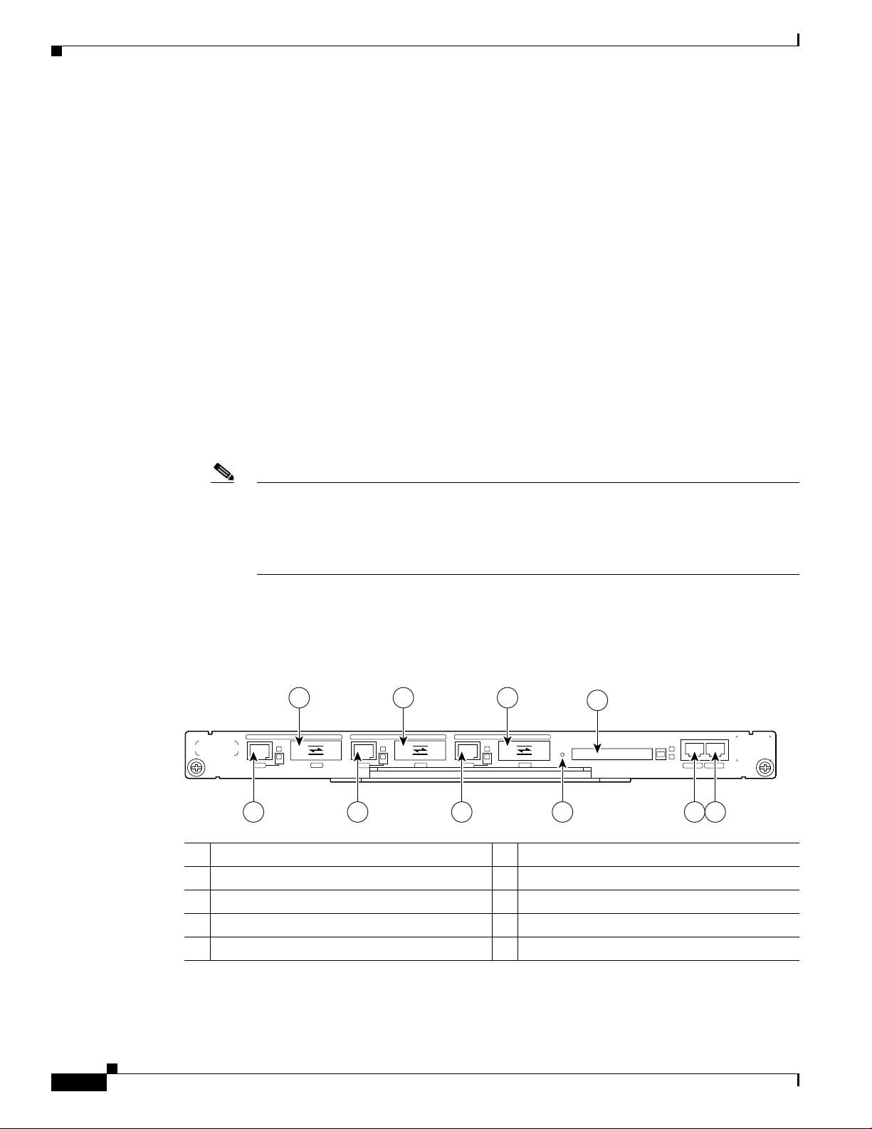
NPE-G1 Description and Overview
66436
COMPACT FLASH
GIGABIT ETHERNET 0/1
RJ45 GBIC
EN
RX TX
LINK
CONSOLE AUX
GIGABIT ETHERNET 0/1
RJ45 GBIC
EN
RX TX
LINK
GIGABIT ETHERNET 0/1
RJ45 GBIC
EN
RX TX
LINK
CPU
RESET
POWER
ON
SLOT
ACTIVE
NETWORK PROCESSING ENGINE - G1
2 4
1 3
6
8
5 7 9 10
–
–
–
–
–
–
–
–
Chapter 5 NPE-G1 Overview
Three Gigabit Ethernet interfaces (six ports: three GBIC [optical] and three RJ-45s [copper]).
Any three ports are available at the same time and are linked directly to the BCM1250 system;
therefore the interfaces are not charged bandwidth points.
CompactFlash Disk for storing the default Cisco IOS software image. The CompactFlash Disk
slot can be used whether or not an I/O controller is in the router.
Auxiliary port with full data terminal equipment (DTE) functionality. (Functional when an I/O
controller is not present. If an I/O controller is present, its auxiliary port is the default port.)
Console port with full data communications equipment (DCE) functionality. (Functional when
an I/O controller is not present. If an I/O controller is present, its console port is the default
port.)
Boot ROM for storing sufficient code for booting the Cisco IOS software.
Flash memory for storing the boot helper (boot loader) image. (The boot helper image comes
installed on the NPE-G1.) If an I/O controller is present, its flash memory is no longer available.
NVRAM for storing the system configuration and environmental monitoring logs. NVRAM
uses lithium batteries to maintain its contents when disconnected from power. If an I/O
controller is present, its NVRAM memory is no longer available.
Upgradable memory modules
Note An I/O controller can be used with the NPE-G1, but an I/O controller is not necessary for
Interfaces and LEDs
Figure 5-2 NPE-G1 Interfaces
1 Fast Ethernet/Gigabit Ethernet RJ-45 port 0/1 6 Gigabit Ethernet port 0/3
2 Gigabit Ethernet port 0/1 7 CPU Reset
3 Fast Ethernet/Gigabit Ethernet RJ-45 port 0/2 8 CompactFlash Disk slot (disk2)
4 Gigabit Ethernet port 0/2 9 Console port
5 Fast Ethernet/Gigabit Ethernet RJ-45 port 0/3 10 Auxiliary port
system functionality. Installing an I/O controller in a chassis with the NPE-G1 activates the
console and auxiliary ports on the I/O controller and automatically disables the console and
auxiliary ports on the NPE-G1. However, you can still use the CompactFlash Disk slots and
Ethernet ports on both the NPE-G1 and I/O controller when both cards are installed.
Network Processing Engine and Network Services Engine Installation and Configuration
5-4
The three interfaces on the NPE-G1 consist of three Gigabit Interface Converter (GBIC) ports and three
10/100/1000 Fast Ethernet/Gigabit Ethernet ports. The rules for using these ports are:
OL-4448-12
Page 47
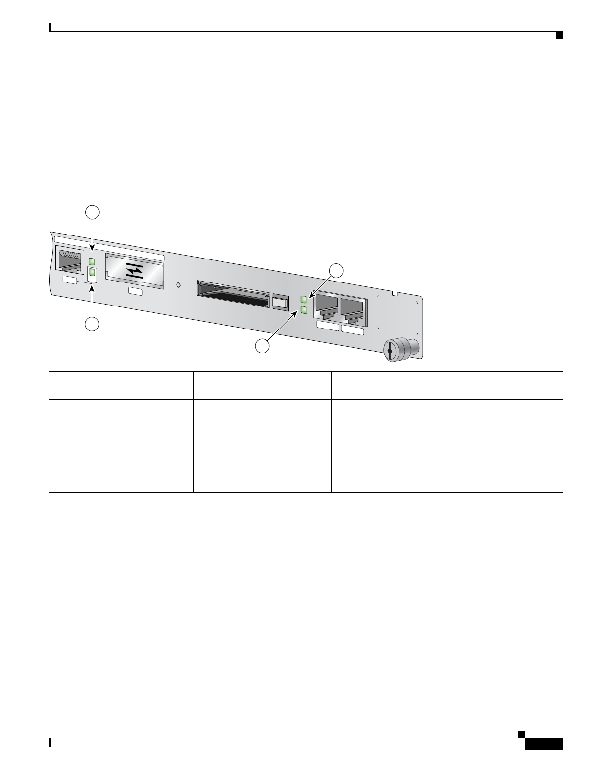
Chapter 5 NPE-G1 Overview
66873
GIGABIT ETHERNET 0/3
RJ45
RX
TX
LINK
EN
GBIC
CONSOLE
AUX
CPU
RESET
COMPACT FLASH
POWER
ON
SLOT
ACTIVE
NETWORK PROCESSING ENGINE - G1
1
2
3
4
• Only one port per interface can be used at any one time. For example, for interface
Gigabit
• A total of three ports on any of the three interfaces (0/1, 0/2, or 0/3) can be used at any one time; for
example, 0/1 GBIC, 0/2 GBIC, and 0/3 RJ-45.
• The port numbering for the interfaces on the NPE-G1 start with 0/1 and not with 0/0, as is typical
for other interface cards. This is to avoid conflicts with the Ethernet and FastEthernet ports on an
I/O controller, if it is also installed.
Figure 5-3 NPE-G1 LEDs
NPE-G1 Description and Overview
Ethernet 0/1, either the RJ-45 port can be used or the GBIC port, but not both.
No. LED Label LED Color In the Power Up state, the LED is
1 LINK (Interfaces 0/1, 0/2,
0/3)
2 EN (Enable) (Interfaces
0/1, 0/2, 0/3)
3 SLOT ACTIVE CompactFlash Disk Green On when the slot is being used —
4 POWER ON Power Green On and stays on No
CompactFlash Disk
OL-4448-12
RJ-45 and GBIC ports Green On, indicating that a link has been
RJ-45 ports only Green On if the RJ-45 port is selected
The NPE-G1 faceplate contains LEDs that indicate system and port status. The RJ-45 and GBIC ports
share the same LINK LED because only one of these ports per interface (0/1, 0/2, or 0/3) can be used at
any one time. The EN (Enable) LED is on if the RJ-45 port is in use.
The POWER ON LED is on whether or not an I/O controller is present in the router. The CompactFlash
Disk slot can be used whether or not an I/O controller is present in the router. The SLOT ACTIVE LED
is on only when the CompactFlash Disk slot is in use.
LEDs are either on or off. The LED state (on or off), not the color, determines the status of the
connection.
The NPE-G1 has one CompactFlash Disk slot that uses CompactFlash Disks. The device in this slot is
always addressed as disk2: when using Cisco
established
Off if the GBIC port is selected
Network Processing Engine and Network Services Engine Installation and Configuration
IOS CLI commands.
LED flashes when
there is traffic
No
—
5-5
Page 48

NPE-G1 Description and Overview
C
F
A
C
T
V
NETWORK PROCESSING ENGINE - G2
C
O
M
P
A
C
T F
LAS
H
C
F
A
C
T
V
NETWORK PROCESSING ENGINE - G2
C
O
M
PA
C
T FLA
S
H
C
F
A
C
T
V
NETWORK PROCESSING ENGINE - G2
C
O
M
P
A
C
T F
LAS
H
1 32
149064
CompactFlash Disks are smaller in size than Type 2 Flash Disks but provide the same Attachment (ATA)
interface and equivalent functionality. This interface complies with the ANSI ATA Interface Document
X3T13.1153 D Rev.
space.
The CompactFlash Disk has controller circuitry that allows it to emulate a hard disk and automatically
maps out bad blocks and performs automatic block erasure. The CompactFlash Disk also provides the
capability to allocate noncontiguous sectors, which eliminates the need for the squeeze command (which
was required with older-style linear flash memory cards to recover the space used by deleted files).
The CompactFlash Disk also supports the Cisco IOS File System feature, which provides a single
interface to all of the router’s file systems, including the Flash Disks and flash memory, as well as
network file systems such as File Transfer Protocol (FTP) and Trivial FTP (TFTP) servers.
To install a CompactFlash Disk in the CompactFlash Disk slot, complete the following steps.
Step 1 Attach an ESD wrist or ankle strap, connecting the equipment end of the strap to an unfinished chassis
surface.
Step 2 Orient the CompactFlash Disk so that its connector end faces the appropriate slot. (See 1 in Figure 5-4.)
Chapter 5 NPE-G1 Overview
9 specification. CompactFlash Disks provide from 64 MB to 256 MB of storage
Figure 5-4 Installing and Removing a CompactFlash Disk
1 Inserting the compact Flash Disk 3 Removing the CompactFlash Disk
2 Pressing the ejector button to release the
CompactFlash Disk
Step 3 Carefully insert the CompactFlash Disk into the slot until it completely seats in the connector, and the
ejector button for the slot pops out toward you. (See 2 in
Figure 5-4.)
Note The CompactFlash Disk is keyed and cannot be seated the wrong way. The ejector button does not pop
]
Network Processing Engine and Network Services Engine Installation and Configuration
5-6
out if the CompactFlash Disk is not completely inserted.
OL-4448-12
Page 49

Chapter 5 NPE-G1 Overview
To remove a CompactFlash Disk from the CompactFlash Disk slot, complete the following steps:
Step 1 Press the ejector button on the slot. (See 3 in Figure 5-4.)
Step 2 Grasp the CompactFlash Disk and pull it from the slot.
Step 3 Place the CompactFlash Disk in an antistatic bag.
Note All CompactFlash Disks must be formatted before their initial use. CompactFlash Disks shipped with
the NPE-G1 are formatted at the factory, but spare memory cards are not formatted.
Summary of Important NPE-G1 Information
Caution The NPE-G1 requires that you copy and save your running configuration file to a CompactFlash Disk,
PC Card, or TFTP server before you install the NPE-G1. For instructions on copying and saving your
configuration file, see the
and NPE-G2 Installation and Configuration Information.”
For general preparation for installation instructions, see Chapter 8, “Preparation for Installation.” For
installation and configuration instructions specific to the NPE-G1, see Chapter 7, “NPE-G1 and NPE-G2
Installation and Configuration Information.”
“Copying the Configuration File” section on page 7-4 in Chapter 7, “NPE-G1
NPE-G1 Description and Overview
• The RJ-45 ports and GBIC ports are both reported in software as GigabitEthernet 0/1,
GigabitEthernet 0/2, and GigabitEthernet 0/3. Only one of the pair of interface ports can be used at
a time; for example, GBIC GigabitEthernet 0/2 or RJ-45 GigabitEthernet 0/2.
• The I/O controller GE/E interface reports GigabitEthernet 0/0 and Ethernet 0/0, and the I/O
controller 2FE/E interface reports FastEthernet
• If the RJ-45 port is in use, the EN (Enable) LED is on. If the GBIC is in use, the EN (Enable) LED
0/0 and FastEthernet 0/1.
is off.
• With the NPE-G1 and an I/O controller both installed, the I/O controller functionality on the
NPE-G1 is shared with that of the I/O controller.
• When both an NPE-G1 and an I/O controller are installed, the flash memory and NVRAM of the
NPE-G1 are enabled and the flash memory and NVRAM on the I/O controller are no longer
accessible.
• The console and auxiliary ports on the NPE-G1 are disabled by Cisco IOS when an I/O controller is
present; the console and auxiliary ports on the I/O controller are active.
• Console port messages can be routed to the auxiliary port on either the NPE-G1 or on the I/O
controller.
• The default media is the RJ-45 port. To change the media type, use the media-type command.
• Only the port selected by the media-type command is active. A cable attached to the other of the
RJ-45 and GBIC pair will be ignored. For example, if GBIC GigabitEthernet 0/2 is selected using
the media-type command, RJ-45 GigabitEthernet 0/2 is ignored, even if a cable is attached to
RJ-45 0/2.
OL-4448-12
Network Processing Engine and Network Services Engine Installation and Configuration
5-7
Page 50

NPE-G1 Description and Overview
• The NPE-G1 uses no bandwidth points, and when used with any I/O controller, the I/O controller
also uses no bandwidth points. None of the Gigabit Ethernet interfaces on the NPE-G1 use
bandwidth points.
• The CompactFlash Disk on the NPE-G1 is available at all times, with or without an I/O controller
installed. The CompactFlash Disk is always addressed as the disk2 device, to avoid conflicts with
the disk0 and disk1 devices on the I/O controller, if the I/O controller is also installed.
Note The Gigabit Ethernet interfaces on the NPE-G1 do not support the Inter-Switch Link (ISL) VLAN
encapsulation protocol. We recommend that customers use the IEEE 802.1Q VLAN encapsulation
protocol as an alternative. Where an application requires the use of ISL, this can be provided by the Fast
Ethernet or Gigabit Ethernet port adapters or I/O controllers.
System Management Functions
The NPE-G1 performs the following system management functions:
• Sending and receiving routing protocol updates
• Managing tables, caches, and buffers
• Monitoring interface and environmental status
Chapter 5 NPE-G1 Overview
• Providing Simple Network Management Protocol (SNMP) management through the console and
Telnet interface
• Accounting for and switching of data traffic
• Booting and reloading images
• Managing port adapters (including recognition and initialization during online insertion and
removal)
Terms and Acronyms
• Boot ROM—Read-only memory that stores the boot image for bringing up the Cisco IOS image
• Cache—Memory with fast access and small capacity used to temporarily store recently accessed
data; found either incorporated into the processor or near it
• DDR SDRAM—double data rate synchronous dynamic random-access memory
• CWDM GBIC—Coarse Wavelength-Division Multiplexing Gigabit Interface Converter
• Flash memory—Location where the basic boot image is stored
• Instruction and data cache—Instructions to the processor, and data on which the instructions work
• Integrated cache—Cache that is built into the processor; sometimes referred to as internal cache.
Cache memory physically located outside the processor is not integrated, and is sometimes referred
to as external cache.
• LDT bus—lightning data transport bus
5-8
• NVRAM—nonvolatile random-access memory
• OTP—one time programmable
Network Processing Engine and Network Services Engine Installation and Configuration
OL-4448-12
Page 51

Chapter 5 NPE-G1 Overview
• Primary and secondary cache—Hierarchical cache memory storage based on the proximity of the
cache to the core of the processor. Primary cache is closest to the processor core and has the fastest
access. Secondary cache has slower access than primary cache.
• RAM—random-access memory
• RISC—reduced instruction set computing
• ROM—read-only memory
• SDRAM—synchronous dynamic random-access memory
• SDRAM-fixed—SDRAM of a fixed size or quantity; can be replaced, but not upgraded
• SODIMM—small outline dual in-line memory module
• Unified cache—Instruction cache and data cache are combined. For example, a processor may have
primary cache with separate instruction and data cache memory, but unified secondary cache.
NPE-G1 Memory Information
To determine the memory configuration of your NPE-G1, use the show version command.
The following example shows an NPE-G1 installed in a Cisco 7206VXR router. The display for a
Cisco
uBR7246VXR router is similar.
NPE-G1 Memory Information
Router# show version
Cisco Internetwork Operating System Software
IOS (tm) 7200 Software (C7200-P-M), Experimental Version
12.2(20011112:161132)
Copyright (c) 1986-2001 by cisco Systems, Inc.
Compiled Tue 13-Nov-01 03:58 by
Image text-base:0x600089B8, data-base:0x6130A000
(display text omitted)
cisco 7206VXR (NPE-G1) processor (revision 0x00) with 245760K/16384K
bytes of memory.
Processor board ID 15191620
BCM12500 CPU at 700Mhz, Implementation 1, Rev 0.1, 512KB L2 Cache
6 slot VXR midplane, Version 2.0
(display text omitted)
Table 5-1 provides memory specifications and Tabl e 5-2 provides user replaceable memory
configuration information for the NPE-G1. Tab le 5-3 provides CompactFlash Disk specifications.
Ta b l e 5-1 NPE-G1 Memory Specifications
Component
Location on the
Memory Type Size Quantity Description
NPE-G1 Board
SDRAM 128 MB, 256 MB, 512 MB 2 128-MB, 256-MB, or 512-MB SODIMMs1J3 and J4
Boot ROM 512 KB 1 Reprogrammable Boot ROM for the ROM
U1
monitor program
Flash memory 16 MB 1 Contains the default boot helper (boot
U25 and U26
loader) image
OL-4448-12
Network Processing Engine and Network Services Engine Installation and Configuration
5-9
Page 52

Chapter 5 NPE-G1 Overview
Connection Equipment and Specifications
Table 5-1 NPE-G1 Memory Specifications (continued)
Component
Location on the
Memory Type Size Quantity Description
NVRAM 512 KB 1 Nonvolatile EPROM for the system
configuration file
Primary cache 32 KB (16 KB instruction,
16
KB data)
Secondary cache 512 KB — BCM1250 system, internal, unified cache U22
1. The NPE-G1 requires that locations J3 and J4 always contain two SODIMMs of the same size.
Ta b l e 5-2 NPE-G1 SDRAM SODIMM Configurations—Configurable Memory Only
Total SDRAM SDRAM Bank Quantity Product Number
256 MB J3 and J4 2 128-MB SODIMMs MEM-NPE-G1-256MB=
512 MB J3 and J4 2 256-MB SODIMMs MEM-NPE-G1-512MB=
1 GB J3 and J4 2 512-MB SODIMMs MEM-NPE-G1-1GB=
— BCM1250 system, internal cache U22
NPE-G1 Board
U7
Ta b l e 5-3 NPE-G1 CompactFlash Disk Specifications
Memory Size Product Number
64 MB MEM-NPE-G1-FLD64=
128 MB MEM-NPE-G1-FLD128=
256 MB MEM-NPE-G1-FLD256=
Connection Equipment and Specifications
This section contains connection equipment and pinout information for the Gigabit Ethernet RJ-45 ports,
Gigabit Interface Converter (GBIC) ports, console port, and auxiliary port that are located on the
NPE-G1.
Ethernet and Fast Ethernet RJ-45 Connection Equipment
The NPE-G1 has RJ-45 ports for Ethernet, Fast Ethernet, and Gigabit Ethernet or autosensing Ethernet,
Fast
Ethernet, and Gigabit Ethernet connections. The RJ-45 port supports IEEE 802.3 (Ethernet) and
IEEE
802.3u (Fast Ethernet) interfaces compliant with 10BASET, 100BASETX, and 1000BASET and
1000BASEX specifications.
The RJ-45 ports support standard straight-through and crossover Category 5 UTP cables with RJ-45
connectors. (See
commercially.
Figure 5-5) Cisco does not supply Category 5 UTP cables; these cables are available
5-10
Network Processing Engine and Network Services Engine Installation and Configuration
OL-4448-12
Page 53

Chapter 5 NPE-G1 Overview
57574
12345678
1
Note To comply with EMI EN55022 Class B regulations, shielded Ethernet cables must be used with the
UBR7200-NPE-G1 in the Cisco
UBR7200-NPE-G1.
Figure 5-5 shows an RJ-45 port and connector. Tabl e 5-4 lists the pinouts and signals for the RJ-45 port.
Connection Equipment and Specifications
uBR7246VXR router. Three shielded cables are included with the
Figure 5-5 RJ-45 Port and Connector
1 RJ-45 connector
Warning
To avoid electric shock, do not connect safety extra-low voltage (SELV) circuits to telephone-network
voltage (TNV) circuits. LAN ports contain SELV circuits, and WAN ports contain TNV circuits. Some
LAN and WAN ports both use RJ-45 connectors. Use caution when connecting cables.
Ta b l e 5-4 RJ-45 Port Pinouts
Statement 1021
Pin 10/100 Signal Gigabit Ethernet Signal
1 Tx Data+
1
Tx A+
2 Tx Data– Tx A–
3 Rx Data+
2
Rx B+
4 N/C Tx C+
5 N/C Tx C–
6 Rx Data– Rx B–
7 N/C Rx D+
8 NC Rx D-
1. Tx Data = Transmit Data
2. Rx Data = Receive Data
OL-4448-12
Note With reference to the RJ-45 pinout in Tab l e 5-4, proper common-mode line terminations should be used
for the unused Category 5 UTP cable pairs 4/5 and 7/8. Common-mode termination reduces
electromagnetic interference (EMI).
Depending on your RJ-45 interface cabling requirements, use the pinouts shown in Figure 5-6 and
Figure 5-7 for Gigabit Ethernet straight-through and crossover twisted-pair cable connections. Use
Figure 5-8 for Ethernet/Fast Ethernet straight-through and crossover twisted-pair cable connections.
Network Processing Engine and Network Services Engine Installation and Configuration
5-11
Page 54

Connection Equipment and Specifications
1 2
1 TPO+
2 TPO-
3 TP1+
6 TP1-
1 TP1+
2 TP1-
3 TPO+
6 TPO-
4 TP2+
5 TP2-
7 TP3+
8 TP3-
4 TP3+
5 TP3-
7 TP2+
8 TP2-
129086
1 TPO+
2 TPO-
3 TP1+
6 TP1-
1 TP0+
2 TP0-
3 TP1+
6 TP1-
4 TP2+
5 TP2-
7 TP3+
8 TP3-
4 TP2+
5 TP2-
7 TP3+
8 TP3-
129088
1 2
Figure 5-6 Four Twisted-Pair Straight-Through Cable Schematics for 10/100/1000 and
1 Router 2 Hub
Figure 5-7 Four Twisted-Pair Crossover Cable Schematics for 10/100/1000 and 1000BASET GBIC
Chapter 5 NPE-G1 Overview
1000BASET GBIC Module Ports
Module Ports
5-12
1 Router 2 Hub
Network Processing Engine and Network Services Engine Installation and Configuration
OL-4448-12
Page 55

Chapter 5 NPE-G1 Overview
1 TxD+
2 TxD–
3 RxD+
6 RxD–
1 RxD+
2 RxD–
3 TxD+
6 TxD–
57607
1 TxD+
2 TxD–
3 RxD+
6 RxD–
1 TxD+
2 TxD–
3 RxD+
6 RxD–
1 2
3 34 5
CLASS 1 LASER PRODUCT
LASERPRODUKT DER KLASSE 1
PRODUIT LASER DE CLASSE 1
PRODUCTO LASER CLASE 1
Figure 5-8 Ethernet/Fast Ethernet Straight-Through and Crossover Cable Pinouts
Connection Equipment and Specifications
1 Straight-through cable pinout, Ethernet port
to a hub or repeater
2 Crossover cable pinout, Ethernet port to a
DTE
3 Ethernet port
For straight-through and crossover cable information, see the “Console and Auxiliary Port Connection
Equipment” section on page 5-17.
Gigabit Ethernet GBIC Connection Equipment
The Gigabit Interface Converter (GBIC) port is a 1000-Mbps optical interface in the form of an SC-type
duplex port that supports IEEE 802.3z interfaces compliant with the 1000BASEX standard. (See
Figure 5-10.)
Note The GBIC is a separately orderable part and does not ship installed in your NPE-G1. You must install
the GBIC before you connect the cables to it. (For GBIC installation and cabling instructions, refer to
the Installing the Gigabit Interface Converter document that shipped with your GBIC.)
4 Hub
5 DTE
Warning
Because invisible laser radiation may be emitted from the aperture of the port when no cable is
connected, avoid exposure to laser radiation and do not stare into open apertures.
Figure 5-9 shows the Class 1 warning label that appears on the Gigabit Ethernet optical ports.
Figure 5-9 Laser Class 1 Warning Label
Warning
Class 1 Laser Product.
Statement 1008
OL-4448-12
Network Processing Engine and Network Services Engine Installation and Configuration
Statement 70
5-13
Page 56

Connection Equipment and Specifications
1
2
3
4
66775
ETHERNET 0/1
GBIC
RX
TX
5
6
Figure 5-10 shows the simplex and duplex SC-type connectors on your multimode or single-mode
optical fiber cables. For simplex connectors, two cables are required, one cable for transmit (TX) and a
second cable for receive (RX). For duplex connectors, only one cable that has both TX and RX
connectors is required. You can use either simplex or duplex connectors for the NPE-G1.
Figure 5-10 GBIC Port Connections
Chapter 5 NPE-G1 Overview
1 To external 1000BASEX network 5 RX (GBIC port 0/1)
2 1 duplex connector (TX and RX) 6 TX (GBIC port 0/1)
3 To external 1000BASEX network
4 2 simplex connectors
Table 5-5 describes the available GBIC options.
Ta b l e 5-5 GBIC Options
Product Number GBIC Description
WS-G5484= or
GBIC-SX=
WS-G5486= or
GBIC-LX/LH=
WS-G5487= or
GBIC-ZX=
Short wavelength
(1000BASESX)
Long wavelength/long haul
(1000BASELX/LH)
Extended distance
(1000BASEZX)
Operates on standard multimode
fiber-optic link spans of up to 1804 ft
(550
m).
Operates on single-mode and multimode
fiber-optic link spans of up to 6.2 miles
(10
km).
Operates on ordinary single-mode
fiber-optic link spans of up to 43.5 miles
(70 km). Link spans of up to 62.1 miles
(100 km) are possible using premium
single-mode fiber or dispersion-shifted
single-mode fiber.
Network Processing Engine and Network Services Engine Installation and Configuration
5-14
OL-4448-12
Page 57

Chapter 5 NPE-G1 Overview
Table 5-6 lists the available CWDM GBIC options.
Ta b l e 5-6 CWDM GBIC Options
Product Number CWDM GBIC Color
CWDM-GBIC-1470= Cisco 1000BASE-CWDM GBIC-1470 nm Gray
CWDM-GBIC-1490= Cisco 1000BASE-CWDM GBIC-1490 nm Violet
CWDM-GBIC-1510= Cisco 1000BASE-CWDM GBIC-1510 nm Blue
CWDM-GBIC-1530= Cisco 1000BASE-CWDM GBIC-1530 nm Green
CWDM-GBIC-1550= Cisco 1000BASE-CWDM GBIC-1550 nm Yell ow
CWDM-GBIC-1570= Cisco 1000BASE-CWDM GBIC-1570 nm Orange
CWDM-GBIC-1590= Cisco 1000BASE-CWDM GBIC-1590 nm Red
CWDM-GBIC-1610= Cisco 1000BASE-CWDM GBIC-1610 nm Brown
Table 5-7 provides cabling specifications for the GBICs that you install in Gigabit Ethernet devices.
Note that all GBIC ports have SC-type connectors. Also, the minimum cable distance for the WS-G5484
or GBIC-SX and WS-G5486 or GBIC-LX/LH (multimode fiber [MMF] and single-mode fiber [SMF])
is 6.5 feet (2 m), and the minimum link distance for the WS-G5487 or GBIC-ZX is 6.2 miles (10 km)
with an 8-dB attenuator installed at each end of the link. Without attenuators, the minimum link distance
for the WS-G5487 or GBIC-ZX is 24.9 miles (40
Connection Equipment and Specifications
km).
Note Optical fiber cables are commercially available; they are not available from Cisco.
Ta b l e 5-7 GBIC Port Cabling Specifications
Modal
Bandwidth
(MHz/km)
GBIC
WS-G5484 or
GBIC-SX
Wavelength
(nm)
Fiber Type
850 MMF
Core Size
(micron)
1
62.5 160 722 ft (220 m)
62.5 200 902 ft (275 m)
50.0 400 1640 ft (500 m)
50.0 500 1804 ft (550 m)
WS-G5486 or
GBIC-LX/LH
1300 MMF2 and
SMF
62.5 500 1804 ft (550 m)
50.0 400 1804 ft (550 m)
50.0 500 1804 ft (550 m)
9/10 — 6.2 miles
WS-G5487 or
1550 SMF 9/10 — 43.5 miles
GBIC-ZX
3
SMF
1. Multimode fiber (MMF) only.
8 — 62.1 miles
Maximum
Cable Distance
(10
km)
(70
km)
(100
km)
OL-4448-12
Network Processing Engine and Network Services Engine Installation and Configuration
5-15
Page 58

Connection Equipment and Specifications
2. A mode-conditioning patch cord is required.
When using the WS-G5486 or GBIC-LX/LH with 62.5-micron diameter MMF, you must install a mode-conditioning patch
cord between the GBIC and the MMF cable on both the transmit and the receive ends of the link when link distances are
greater than 984
very short link distances (tens of meters). The result could be an elevated bit error rate (BER).
3. Dispersion-shifted single-mode optical fiber cable.
Table 5-8 provides the GBIC transmit and receive power requirements and power budget.
Ta b l e 5-8 GBIC Power Requirements and Power Budget
Chapter 5 NPE-G1 Overview
ft (300 m). We do not recommend using the WS-G5486 or GBIC-LX/LH and MMF with no patch cord for
Transmit Power
GBIC
WS-G5484 or
Minimum Maximum
–9.5 dBm
1
GBIC-SX
WS-G5486 or
GBIC-LX/LH
WS-G5487 or
–9.5 dBm
–11.5dBm
0 dBm 5.2 dBm –24 dBm –3 dBm –24 dBm
3
4
GBIC-ZX
1. For fiber types 50/125 μm, NA = 0.20 fiber and 62.5/125 μm, NA = 0.275 fiber.
2. For fiber types 50 μm MMF and 62.5 μm MMF.
3. For fiber types 9/125 μm SMF.
4. For fiber types 62.5/125 μm MMF and 50/125 μm MMF.
5. For fiber types 9/125 μm SMF, 62.5/125 μm MMF, and 50/125 μm MMF.
6. For fiber types 50 μm MMF and 62.5 μm MMF.
7. For fiber type 10 μm SMF.
Mode-Conditioning Patch Cord Description
A mode-conditioning patch cord can be used with the WS-G5486= or GBIC-LX/LH= to allow reliable
laser transmission between the single-mode laser source on the GBIC and a multimode optical fiber
cable.
When an unconditioned laser source designed for operation on single-mode optical fiber is directly
coupled to a multimode optical fiber cable, an effect known as differential mode delay (DMD) might
result in a degradation of the modal bandwidth of the optical fiber cable.
–4 dBm
–3 dBm
Receive Power
Minimum Maximum Power Budget
1
–17 dBm 0 dBm 7.5 dBm
5
–20 dBm –3 dBm 7.5 dBm6 and 8.0 dBm
2
7
5-16
This degradation results in a decrease in the link span (the distance between a transmitter and a receiver)
that can be supported reliably. The effect of DMD can be overcome by conditioning the launch
characteristics of a laser source. A practical means of performing this conditioning is to use a device
called a mode-conditioning patch cord.
A mode-conditioning patch cord is an optical fiber cable assembly that consists of a pair of optical fibers
terminated with connector hardware. Specifically, the mode-conditioning patch cord is composed of a
single-mode optical fiber permanently coupled off-center (see Offset in
multimode optical fiber. Figure 5-11 shows a diagram of the mode-conditioning patch cord assembly.
Network Processing Engine and Network Services Engine Installation and Configuration
Figure 5-11) to a graded-index
OL-4448-12
Page 59

Chapter 5 NPE-G1 Overview
/ / / /
/ /
TX
Offset
RX
57011
1 1
1
2
3
4 5
6
9
87 6
Figure 5-11 Mode Conditioning Patch Cord
1 Beige color identifier 6 Multimode fiber
2 To Gigabit Ethernet interface 7 Single-mode fiber
3 RX 8 Offset
4 TX 9 To cable plant
5 Blue color identifier
Connection Equipment and Specifications
The mode-conditioning patch cord assembly is composed of duplex optical fibers, including a
single-mode-to-multimode offset launch fiber connected to the transmitter, and a second conventional
graded-index multimode optical fiber connected to the receiver. The use of a plug-to-plug patch cord
maximizes the power budget of multimode 1000BASELX and 1000BASELH links.
The mode-conditioning patch cord is required to comply with IEEE standards. The IEEE found that link
distances could not be met with certain types of fiber-optic cable cores. The solution is to launch light
from the laser at a precise offset from the center, which is accomplished by using the mode-conditioning
patch cord. At the output of the patch cord, the WS-G5486 or GBIC-LX/LH is compliant with the IEEE
802.3z standard for 1000BASELX.
Console and Auxiliary Port Connection Equipment
The NPE-G1 has a DCE-mode console port for connecting a console terminal, and a DTE-mode
auxiliary port for connecting a modem or other DCE device (such as a CSU/DSU or other router) to your
router. However, with an I/O controller also installed in the router, the default console and auxiliary ports
are on the I/O controller, and you cannot access the console and auxiliary ports on the NPE-G1.
Note Both the console and the auxiliary ports are asynchronous serial ports; any devices connected to these
ports must be capable of asynchronous transmission. (Asynchronous is the most common type of serial
device; for example, most modems are asynchronous devices.)
The NPE-G1 uses RJ-45 media for console port and auxiliary port connections.
Before connecting a terminal to the console port, configure the terminal to match the router console port
as follows: 9600 baud, 8 data bits, no parity, 2 stop bits (9600 8N2). After you establish normal router
operation, you can disconnect the terminal.
OL-4448-12
Network Processing Engine and Network Services Engine Installation and Configuration
5-17
Page 60
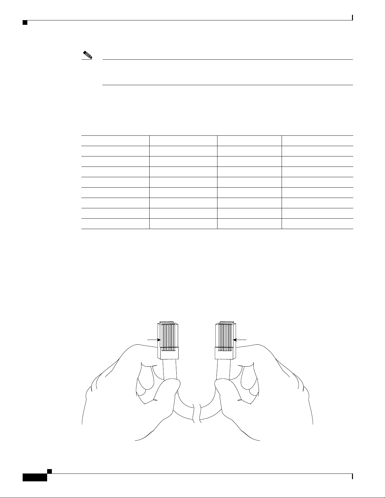
Connection Equipment and Specifications
Pin 1
Pin 8
H3824
Pin 1 and pin 8
should be the
same color
Note When connecting to an auxiliary port on a Cisco 7200 VXR router, the port will not function at baud
rates higher than 19.2k. If the baud rate on the connecting device is set higher than 19.2k, either
garbled text or nothing will be displayed on the screen.
Refer to Ta b le 5-9 for a list of the pins used on the RJ-45-to-DB-25 adapters, used with an RJ-45 cable,
to connect terminals and modems to the Cisco 7200 series routers. The cable you use may be a roll-over
cable or a straight cable.
Ta b l e 5-9 Pinouts for the RJ-45-to-DB-25 Adapters
Chapter 5 NPE-G1 Overview
Adapter DTE M/F Pins
1
DCE M/F Pins MMOD Pins
2
1 4 5 5
2 20 6 8
3 2 3 3
4 7 7 7
5 7 7 7
6 3 2 2
7 6 20 20
8 5 4 4
1. The female data terminal equipment (FDTE) adapter that is available from Cisco is labeled “Terminal”.
2. The MMOD adapter that is available from Cisco is labeled “Modem”.
A roll-over cable can be detected by comparing the two modular ends of the cable. Holding the cables
in your hand, side-by-side, with the tab at the back, the wire connected to the pin on the outside of the
left plug should be the same color as the pin on the outside of the right plug. If your cable was purchased
from Cisco, pin 1 will be white on one connector, and pin 8 will be white on the other (a roll-over cable
reverses pins 1 and 8, 2 and 7, 3 and 6, and 4 and 5). (See
Figure 5-12 Identifying a Roll-Over Cable
Figure 5-12.)
5-18
Network Processing Engine and Network Services Engine Installation and Configuration
OL-4448-12
Page 61
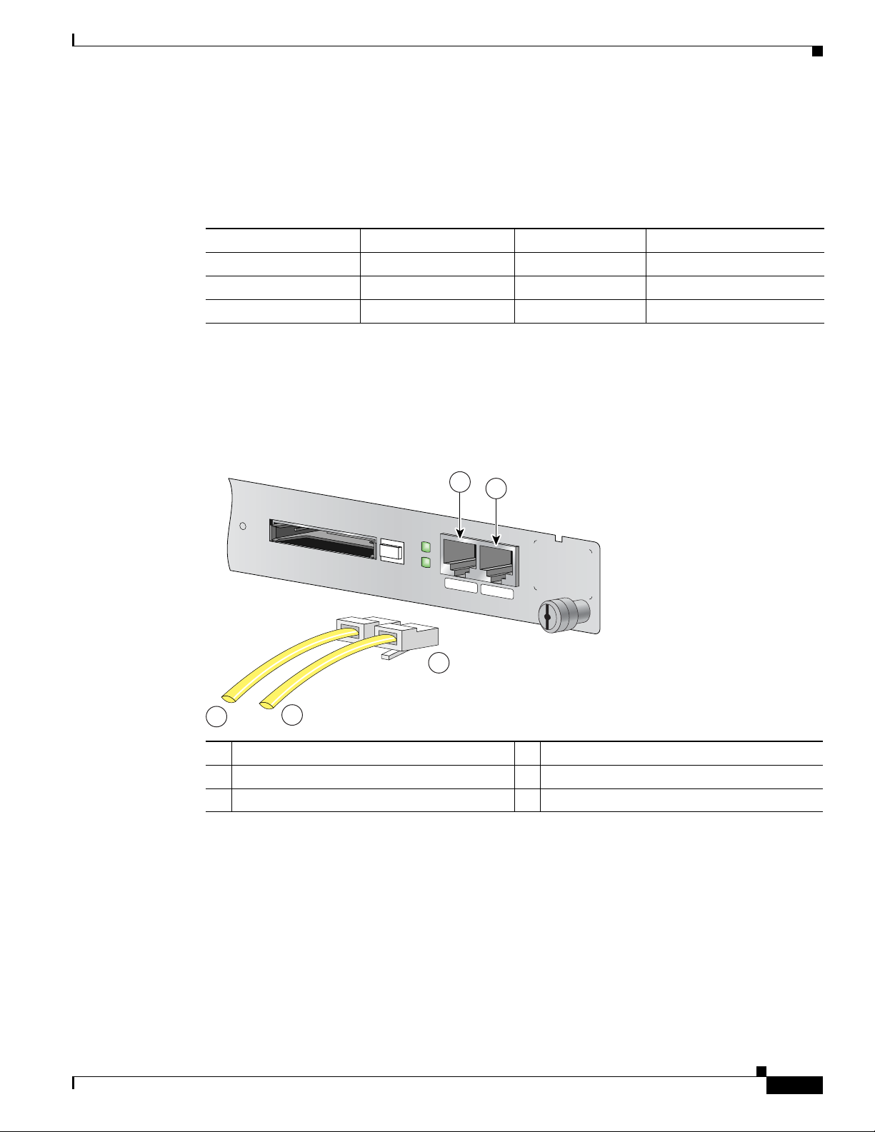
Chapter 5 NPE-G1 Overview
CONSOLE
AUX
CPU
RESET
COMPACT FLASH
POWER
ON
SLOT
ACTIVE
NETWORK PROCESSING ENGINE - G1
66777
1
2
3
4
5
The Cisco 7200 series routers ship with a roll-over cable. Connection to a terminal or a modem requires
an RJ-45-to-DB-25 adapter, and possibly a DB-25-to-DB9 adapter. Refer to
adapter configurations that can be used to connect terminals and modems to the Cisco 7200 series
routers.
Ta b l e 5-10 Asynchronous Device Cabling Options
Access Server Port RJ-45 Cable Type DB-25 Adapter End Device
Console or auxiliary Roll-over FDTE
Console or auxiliary Straight FDCE Termi n a l
Auxiliary or console Roll-over MMOD
1. The FDTE RJ-45-to-DB-25 adapter is labeled “Terminal”.
2. The MMOD RJ-45-to-DB-25 adapter is labeled “Modem”.
The cable and auxiliary ports are configured as asynchronous serial ports. Figure 5-13 shows the RJ-45
console and auxiliary port connections.
Figure 5-13 Console and Auxiliary Port RJ-45 Connections
Connection Equipment and Specifications
Table 5-10 for the cable and
1
2
Ter m i n a l
Modem
RJ-45 Console Port Signals and Pinouts
OL-4448-12
1 Console port 4 Cable to console terminal or DTE
2 Auxiliary port 5 Cable to modem or DCE
3 RJ-45 connectors
A cable and adapter kit is available from Cisco (Product Number ACS-2500ASYN=). Tab le 5-10
describes the cable and adapter configurations that can be used to connect terminals and modems to the
console or the auxiliary port.
The NPE-G1 console port supports Data Carrier Detect (DCD). Table 5-11 lists the RJ-45 console port
signals for the NPE-G1.
Network Processing Engine and Network Services Engine Installation and Configuration
5-19
Page 62

Fiber Optic Cleaning Information
Ta b l e 5-11 Console Port Signals for the NPE-G1
1
Pin
Signal Direction Description
1 CTS Out Clear To Send (tracks RTS)
2 DSR Out Data Set Ready (always on)
3 RXD Out Receive Data
4 GND — Signal Ground
6 TXD In Transmit Data
7 DTR In Data Terminal Ready
8 RTS In Ready To Send
1. Any pin not referenced is not connected.
RJ-45 Auxiliary Port Signals and Pinouts
Table 5-12 lists the RJ-45 auxiliary port signals for the NPE-G1.
Ta b l e 5-12 Auxiliary Port Signals for the NPE-G1
Chapter 5 NPE-G1 Overview
1
Pin
Signal Direction Description
1 RTS Out Ready To Send
2 DTR Out Data Terminal Ready
3 TXD Out Transmit Data
4 RING
2
In Ring Indication
5 GND — Signal Ground
6 RXD In Receive Data
3
7
DSR/DCD(RLSD) In Data Set Ready/Data Carrier Detect (Receive Line Signal
8 CTS In Clear To Send (tracks RTS)
1. Any pin not referenced is not connected.
2. RING is not supported on Cisco-supplied adapters. To use this pin, you must create a customized cable.
3. Pin 7 can be used as a DCD input for connection to a modem. The RJ-45-to-DB-25F adapter maps DCD to this pin when
used with a straight-through cable.
Fiber Optic Cleaning Information
We strongly recommend cleaning all optical fiber connections before reconnecting optical cables to
equipment. For information about cleaning optical connectors, see the
Procedures for Fiber-Optic Connections document and the Compressed Air Cleaning Issues for
Fiber-Optic Connections document.
Detect)
Inspection and Cleaning
5-20
Network Processing Engine and Network Services Engine Installation and Configuration
OL-4448-12
Page 63

CHAP T ER
6
NPE-G2 Overview
This chapter describes the NPE-G2 and contains the following sections:
• Supported Platforms, page 6-1
• Software Requirements, page 6-2
• NPE-G2 Description and Overview, page 6-2
• NPE-G2 Memory Information and Specifications, page 6-11
• Fiber Optic Cleaning Information, page 6-23
Caution You must copy and save your running configuration file to a CompactFlash Disk, PC Card, or TFTP
server before you install the NPE-G2. For instructions on copying and saving your configuration file, see
the
“Copying the Configuration File” section on page 7-4 in Chapter 7, “NPE-G1 and NPE-G2
Installation and Configuration Information.”
For general preparation for installation instructions, see Chapter 8, “Preparation for Installation.” For
installation and configuration instructions specific to the NPE-G2, see Chapter 7, “NPE-G1 and NPE-G2
Installation and Configuration Information.”
Supported Platforms
The NPE-G2 is supported on the Cisco 7200 VXR routers and Cisco uBR7200 series routers. For the
Cisco
7200 VXR routers, order Part Number NPE-G2 or NPE-G2=. For the Cisco uBR7200 series
routers, order Part Number UBR7200-NPE-G2 or UBR7200-NPE-G2=.
Note Unless otherwise indicated, all references to NPE-G2 in this document also refer to UBR7200-NPE-G2.
OL-4448-12
Network Processing Engine and Network Services Engine Installation and Configuration
6-1
Page 64

Software Requirements
Software Requirements
For minimum software release information, see the “Software Requirements” section on page 8-4.
Note The NPE-G2 has its own Cisco IOS software image with the prefix “c7200p-” in the software images
filenames, including the boot image. The NPE-G2 does not boot up with a software image with the prefix
“c7200-”. Previous network processing engines, or the network services engine, do not boot up with the
“c7200p-” boot image. They use the prefix “c7200-”.
NPE-G2 Description and Overview
This section contains information about the NPE-G2 components and the system management functions.
The following information is in this section:
• Bandwidth Requirements, page 6-3
• Components, page 6-3
• Interfaces, page 6-4
• LEDs, page 6-5
Chapter 6 NPE-G2 Overview
• CompactFlash Disk, page 6-6
• USB Ports, page 6-8
• Summary of Important NPE-G2 Information, page 6-9
• System Management Functions, page 6-10
• Terms and Acronyms, page 6-10
Like the NPE-G1, the NPE-G2 provides the functionality of both a network processing engine and I/O
controller. If used without an I/O controller, an I/O controller blank panel must be in place.
While its design provides I/O controller functionality, it can also work with any I/O controller supported
in the Cisco 7200 VXR routers or Cisco uBR7200 series routers. The NPE-G2, when installed with an
I/O controller, provides the bootflash and NVRAM that the Cisco
Note An I/O controller can be used with the NPE-G2, but an I/O controller is not necessary for system
functionality. Installing an I/O controller in a chassis with the NPE-G2 activates the console and
auxiliary ports on the I/O controller and automatically disables the console and auxiliary ports on the
NPE-G2. However, you can still use the CompactFlash Disk slots and Ethernet ports on both the NPE-G2
and I/O controller when both cards are installed.
The NPE-G2 maintains and executes the system management functions for the Cisco 7200 VXR routers
and Cisco
functions. The NPE-G2 consists of one board with multiple interfaces.
The NPE-G2 can be used with the Port Adapter Jacket Card installed in the I/O controller slot. If you
are upgrading to an NPE-G2 and Port Adapter Jacket Card at the same time, see the Por t A d apter Jacket
Card Installation Guide for information about the order of installation of both the NPE-G2 and the Port
Adapter Jacket Card.
uBR7200 series routers and also holds the system memory and environmental monitoring
IOS software uses to boot.
6-2
Network Processing Engine and Network Services Engine Installation and Configuration
OL-4448-12
Page 65

Chapter 6 NPE-G2 Overview
149061
3
1
9
7
8
10
2
5
6
4
Bandwidth Requirements
The Gigabit Ethernet ports on the NPE-G2 do not use bandwidth points, nor does the Fast Ethernet
management port. When used with any I/O controller, the Ethernet ports, Fast Ethernet ports, or Gigabit
Ethernet ports on the I/O controller also do not use bandwidth points.
Components
Figure 6-1 illustrates the NPE-G2 and its major components.
Figure 6-1 NPE-G2
NPE-G2 Description and Overview
OL-4448-12
1 Midplane connectors 6 Flash memory (U13)
2 Boot ROM (U24) 7 DIMM (socket—S1)
3 NVRAM (on bottom of board—U17) 8 Temperature sensor (inlet—U23)
4 Temperature sensor (outlet—U20) 9 Processor (U30)
5 Flash memory (U19) 10 Keying post
The NPE-G2 consists of the following components:
• Motorola Freescale 7448 processor
–
Microprocessor operates at an internal clock speed of 1.67 GHz.
–
Hardware logic to interconnect the processor, double data rate synchronous dynamic
random-access memory (DDR-SDRAM), lightning data transport (LDT) bus, the generic PCI
bus, and three direct-interface Gigabit Ethernet interfaces.
Network Processing Engine and Network Services Engine Installation and Configuration
6-3
Page 66

NPE-G2 Description and Overview
• Cache memory
The NPE-G2 has two levels of cache: primary and secondary cache that are internal to the
microprocessor with secondary unified cache for data and instruction.
• The NPE-G2 uses DDR SDRAM for providing code, data, and packet storage.
• Two environmental sensors for monitoring the cooling air as it enters and leaves the chassis.
• Full-feature I/O controller functionality
–
–
–
–
–
–
Chapter 6 NPE-G2 Overview
Three Gigabit Ethernet interfaces (six ports: three SFP [optical] and three RJ-45s [copper]).
Any three ports are available at the same time and are linked directly to the processor; therefore
the interfaces are not charged bandwidth points.
CompactFlash Disk for storing the default Cisco IOS software image. The CompactFlash Disk
slot can be used whether or not an I/O controller is in the router.
Auxiliary port with full data terminal equipment (DTE) functionality. (Functional when an I/O
controller is not present. If an I/O controller is present, its auxiliary port is the default port.)
Console port with full data communications equipment (DCE) functionality. (Functional when
an I/O controller is not present. If an I/O controller is present, its console port is the default
port.)
Dedicated 10/100 Fast Ethernet Management port—Not to be used for any other purpose.
Two USB ports for data storage using Cisco USB flash memory modules or security eToken for
VPN applications.
Interfaces
–
Boot ROM for storing the ROMmon images.
–
Internal flash memory for storing the boot helper (boot loader) image and the Cisco IOS image.
(The boot helper image comes installed on the NPE-G2.) If an I/O controller is present, its
internal flash memory is no longer available.
–
NVRAM for storing the system configuration and environmental monitoring logs. NVRAM
uses lithium batteries to maintain its contents when disconnected from power. If an I/O
controller is present, its NVRAM memory is no longer available.
–
Upgradable memory module
Note An I/O controller can be used with the NPE-G2, but an I/O controller is not necessary for
system functionality. Installing an I/O controller in a chassis with the NPE-G2 activates the
console and auxiliary ports on the I/O controller and automatically disables the console and
auxiliary ports on the NPE-G2. However, you can still use the Compact Flash Disk slots and
Ethernet ports on both the NPE-G2 and I/O controller when both cards are installed.
The three interfaces on the NPE-G2 consist of three small form-factor (SFP) Gigabit Ethernet ports and
three 10/100/1000 Fast Ethernet/Gigabit Ethernet ports. The rules for using these ports are:
• Only one port per interface can be used at any one time. For example, for interface
Gigabit
Ethernet 0/1, either the RJ-45 port can be used or the SFP port, but not both.
6-4
• A total of three ports on any of the three interfaces (0/1, 0/2, or 0/3) can be used at any one time; for
example, 0/1 SFP, 0/2 SFP, and 0/3 RJ-45.
Network Processing Engine and Network Services Engine Installation and Configuration
OL-4448-12
Page 67

Chapter 6 NPE-G2 Overview
CPU
RESET
NPE-G2
RJ45
GIGABIT ETHERNET 0 / 1
EN
LINK
ACTV
RJ45
GIGABIT ETHERNET 0 / 2
EN
LINK
ACTV
RJ45 CONSOLE AUX FE 0/2
FOR MANAGEMENT
USE ONLY
GIGABIT ETHERNET 0 / 2
EN
LINK
ACTV
USB
CF
ACTV
U
S
B
NETWORK PROCESSING ENGINE - G2
COMPACT FLASH
FE
LINK
PWR
OK
SYST
STAT
149062
2 4 6 8
31 5 7
10 11 13
9 12
• The port numbering for the interfaces on the NPE-G2 starts with 0/1 and not with 0/0, as is typical
Figure 6-2 NPE-G2 Interfaces
1 CPU Reset 8 Console port
2 Fast Ethernet/Gigabit Ethernet RJ-45 port—GE 0/1 9 Auxiliary port
3 Gigabit Ethernet port—GE 0/1 10 Fast Ethernet Management
4 Fast Ethernet/Gigabit Ethernet RJ-45 port—GE 0/2 11 USB port 0
5 Gigabit Ethernet port—GE 0/2 12 USB port 1
6 Fast Ethernet/Gigabit Ethernet RJ-45 port—GE 0/3 13 CompactFlash Disk slot
7 Gigabit Ethernet port—GE 0/3
NPE-G2 Description and Overview
for other interface cards. This is to avoid conflicts with the Ethernet and Fast Ethernet ports on an
I/O controller, if it is also installed.
port—FE 0/2
Note The Fast Ethernet Management RJ-45 port is only used for management activities—not for any other
purpose.
Note The USB function is not supported on Cisco uBR7200 series routers.
LEDs
This section provides information about the location and behavior of the NPE-G2 LEDs.
The NPE-G2 faceplate contains LEDs that indicate system and port status. The RJ-45 and SFP ports
share the same LINK ACTV LED because only one of these ports per interface (0/1, 0/2, or 0/3) can be
used at any one time. The EN (Enable) LED is on if the RJ-45 port is in use.
The PWR OK LED is on whether or not an I/O controller is present in the router. The CompactFlash
Disk slot can be used whether or not an I/O controller is present in the router. The SYST STAT LED
provides information about the status of the system.
OL-4448-12
Network Processing Engine and Network Services Engine Installation and Configuration
6-5
Page 68

NPE-G2 Description and Overview
149063
RJ45
CONSOLE AUX
FE 0/2
FOR MANAGEMENT
USE ONLY
GIGABIT ETHERNET 0 / 3
EN
LINK
ACTV
USB
CF
ACTV
U
S
B
NETWORK PROCESSING ENGINE - G2
COMPACT FLASH
FE
LINK
PWR
OK
SYST
STAT
6
7
1
2
3
5
4
Figure 6-3 NPE-G2 LEDs
Ta b l e 6-1
No. LED Label LED Color Description
1 LINK ACTV
2 EN (Enable)
3 FE LINK Fast Ethernet
4 USB USB ports Flashing green Activity
5 CF ACTV CompactFlash
6 SYST STAT System status Blinking green Cisco IOS is loading.
7 PWR OK Power Green The NPE-G2 has powered on.
(Interfaces 0/1, 0/2,
0/3)
(Interfaces 0/1, 0/2,
0/3)
Chapter 6 NPE-G2 Overview
RJ-45 and SFP
ports
RJ-45 ports only Solid green RJ-45 port is selected.
Management port
Disk
Solid green Link with no activity
Flashing green Link with activity
Off No link
Off SFP port is selected.
Solid green Link with no activity
Flashing green Link with activity
Off No link
Off No activity
Flashing green Activity
Off No activity
Solid green Cisco IOS has successfully
booted.
Blinking yellow ROMmon is loading.
Solid yellow ROMmon has successfully
booted.
Off No activity
CompactFlash Disk
Network Processing Engine and Network Services Engine Installation and Configuration
6-6
The NPE-G2 has one CompactFlash Disk slot that uses CompactFlash Disks. The device in this slot is
always addressed as disk2: when using Cisco
IOS CLI commands.
OL-4448-12
Page 69

Chapter 6 NPE-G2 Overview
C
F
A
C
T
V
NETWORK PROCESSING ENGINE - G2
C
O
M
P
A
C
T F
LA
S
H
C
F
A
C
T
V
NETWORK PROCESSING ENGINE - G2
C
O
M
P
A
C
T FLA
SH
C
F
A
C
T
V
NETWORK PROCESSING ENGINE - G2
C
O
M
P
A
C
T
FL
A
S
H
1 32
149064
CompactFlash Disks are smaller in size than Type 2 Flash Disks but provide the same Attachment (ATA)
interface and equivalent functionality. This interface complies with the ANSI ATA Interface Document
X3T13.1153 D Rev.
The CompactFlash Disk has controller circuitry that allows it to emulate a hard disk and automatically
maps out bad blocks and performs automatic block erasure. The CompactFlash Disk also provides the
capability to allocate noncontiguous sectors, which eliminates the need for the squeeze command (which
was required with older-style linear flash memory cards to recover the space used by deleted files).
The CompactFlash Disk also supports the Cisco IOS File System feature, which provides a single
interface to all of the router’s file systems, including the Flash Disks and flash memory, as well as
network file systems such as File Transfer Protocol (FTP) and Trivial FTP (TFTP) servers.
Table 6-4 lists the CompactFlash Disk options.
To install a CompactFlash Disk in the CompactFlash Disk slot, complete the following steps
Step 1 Attach an ESD wrist or ankle strap, connecting the equipment end of the strap to an unfinished chassis
surface.
Step 2 Orient the CompactFlash Disk so that its connector end faces the appropriate slot. (See 1 in Figure 6-4.)
NPE-G2 Description and Overview
9 specification. The CompactFlash Disk provides 256 MB of storage space.
Figure 6-4 Installing and Removig a CompactFlash Disk
1 Inserting the compact Flash Disk 3 Removing the CompactFlash Disk
2 Pressing the ejector button to release the
CompactFlash Disk
Step 3 Carefully insert the CompactFlash Disk into the slot until it completely seats in the connector, and the
ejector button for the slot pops out toward you. (See 2 in
Figure 6-4.)
Note The CompactFlash Disk is keyed and cannot be seated the wrong way. The ejector button does not pop
out if the CompactFlash Disk is not completely inserted.
OL-4448-12
Network Processing Engine and Network Services Engine Installation and Configuration
6-7
Page 70

NPE-G2 Description and Overview
Step 1 Press the ejector button on the slot. (See 3 in Figure 6-4.)
Step 2 Grasp the CompactFlash Disk and pull it from the slot.
Step 3 Place the CompactFlash Disk in an antistatic bag.
Note All CompactFlash Disks must be formatted before their initial use. CompactFlash Disks shipped with
USB Ports
Chapter 6 NPE-G2 Overview
To remove a CompactFlash Disk from the CompactFlash Disk slot, complete the following steps:
the NPE-G2 are formatted at the factory, but spare memory cards are not formatted.
The NPE-G2 provides two USB ports that can be used with USB Flash memory modules as secondary
storage, similar to CompactFlash Disks. The USB Flash memory modules can be used to store Cisco IOS
images, data, and configuration files. See
numbers.
Table 6-5 for USB Flash memory module product options and
The NPE-G2 includes USB ports that can be used with Cisco USB Flash memory modules or with the
Aladdin USB eToken Pro key. These USB devices can be used with the NPE-G2 for the following
functions:
• The USB eToken Pro key by Aladdin Knowledge Systems provides a secure means to store and
deploy information, such as a bootstrap configuration or VPN credentials, separate from the router
chassis. The USB eToken uses smart card technology to protect a small area of memory and grants
access using a personal identification number (PIN). When IP Security (IPSec) VPN credentials are
stored on the USB eToken, they are safely external to the router. When the USB eToken is inserted
in a USB port, the router can pass the PIN and unlock it, retrieving the credentials and copying them
into running memory. When the USB eToken is removed, the router will erase the credentials from
running memory, ensuring that they cannot be retrieved from the router itself.
Note For more information about the USB eToken Pro key by Aladdin Knowledge Systems, see
the Aladdin website at www.aladdin.com/etoken/cisco.
• The Cisco USB Flash memory module can be used to store an image or configuration file like a
CompactFlash Disk. Unlike the USB eToken, the Cisco USB Flash memory module is nonsecure.
See
Table 6-5 for available USB Flash memory module configurations and product numbers.
Note The Cisco USB Flash memory module cannot be used to boot the router. The USB drivers
exist only in Cisco IOS software, not ROM Monitor mode (ROMmon). As a result, a Cisco
IOS image must be booted to load the drivers; only then can files be copied to and from the
USB Flash memory module.
6-8
Note For detailed information about the Cisco IOS commands that support USB Flash memory modules, see
the Cisco IOS USB Flash Module and USB eToken Support document.
Network Processing Engine and Network Services Engine Installation and Configuration
OL-4448-12
Page 71

Chapter 6 NPE-G2 Overview
Summary of Important NPE-G2 Information
Caution The NPE-G2 requires that you copy and save your running configuration file to a CompactFlash Disk,
PC Card, or TFTP server before you install the NPE-G2. For instructions on copying and saving your
configuration file, see the
and NPE-G2 Installation and Configuration Information.”
For general preparation for installation instructions, see Chapter 8, “Preparation for Installation.” For
installation and configuration instructions specific to the NPE-G2, see Chapter 7, “NPE-G1 and NPE-G2
Installation and Configuration Information.”
• The NPE-G2 software image and kboot image name begins with “c7200p-”, which is different from
that of previous network processing engines.
• The RJ-45 ports and SFP ports are both reported in software as GigabitEthernet 0/1, GigabitEthernet
0/2, and GigabitEthernet 0/3. Only one of the pair of interface ports can be used at a time; for
example, SFP GigabitEthernet 0/2 or RJ-45 GigabitEthernet 0/2.
• The I/O controller GE/E interface reports GigabitEthernet 0/0 and Ethernet 0/0, and the I/O
controller 2FE/E interface reports FastEthernet
“Copying the Configuration File” section on page 7-4 in Chapter 7, “NPE-G1
NPE-G2 Description and Overview
0/0 and FastEthernet 0/1.
• If the RJ-45 port is in use, the EN (Enable) LED is on. If the SFP port is in use, the EN (Enable)
LED is off.
• With the NPE-G2 and an I/O controller both installed, the I/O controller functionality on the
NPE-G2 is shared with that of the I/O controller.
• When both an NPE-G2 and an I/O controller are installed, the flash memory and NVRAM of the
NPE-G2 are enabled and the flash memory
• and NVRAM on the I/O controller are no longer accessible.
• The console and auxiliary ports on the NPE-G2 are disabled by Cisco IOS when an I/O controller is
present; the console and auxiliary ports on the I/O controller are active.
• Console port messages can be routed to the auxiliary port on either the NPE-G2 or on the I/O
controller.
• The default media is the RJ-45 port. To change the media type, use the media-type command.
• Only the port selected by the media-type command is active. A cable attached to the other of the
RJ-45 and SFP module pair will be ignored. For example, if SFP port GigabitEthernet 0/2 is selected
using the media-type command, RJ-45 GigabitEthernet 0/2 is ignored, even if a cable is attached to
RJ-45
0/2.
• The NPE-G2 uses no bandwidth points, and when used with any I/O controller, the I/O controller
also uses no bandwidth points. None of the Gigabit Ethernet interfaces on the NPE-G2 use
bandwidth points.
• The CompactFlash Disk on the NPE-G2 is available at all times, with or without an I/O controller
installed. The CompactFlash Disk is always addressed as the disk2 device, to avoid conflicts with
the disk0 and disk1 devices on the I/O controller, if the I/O controller is also installed.
• USB Flash memory modules are available for data storage, with or without an I/O controller
installed.
OL-4448-12
Network Processing Engine and Network Services Engine Installation and Configuration
6-9
Page 72

NPE-G2 Description and Overview
Note The Gigabit Ethernet interfaces on the NPE-G2 do not support the Inter-Switch Link (ISL) VLAN
encapsulation protocol. We recommend that customers use the IEEE 802.1Q VLAN encapsulation
protocol as an alternative. Where an application requires the use of ISL, this can be provided by the Fast
Ethernet or Gigabit Ethernet port adapters or I/O controllers.
System Management Functions
The NPE-G2 performs the following system management functions:
• Sending and receiving routing protocol updates
• Managing tables, caches, and buffers
• Monitoring interface and environmental status
• Providing Simple Network Management Protocol (SNMP) management through the console and
Telnet interface
• Accounting for and switching of data traffic
Chapter 6 NPE-G2 Overview
• Booting and reloading images
• Managing port adapters (including recognition and initialization during online insertion and
removal)
Terms and Acronyms
• Boot ROM—Read-only memory that stores the boot image for bringing up the Cisco IOS image.
• Cache—Memory with fast access and small capacity used to temporarily store recently accessed
data; found either incorporated into the processor or near it.
• CWDM— Coarse Wavelength-Division Multiplexing.
• DIMM— Dual In-line Memory Module.
• DDR SDRAM—double data rate synchronous dynamic random-access memory.
• Flash memory—Location where the basic boot image is stored.
• Instruction and data cache—Instructions to the processor, and data on which the instructions work.
• Integrated cache—Cache that is built into the processor; sometimes referred to as internal cache.
Cache memory physically located outside the processor is not integrated, and is sometimes referred
to as external cache.
• LDT bus—lightning data transport bus.
• NVRAM—nonvolatile random-access memory.
6-10
• OTP—one time programmable.
• Primary and secondary cache—Hierarchical cache memory storage based on the proximity of the
cache to the core of the processor. Primary cache is closest to the processor core and has the fastest
access. Secondary cache has slower access than primary cache.
• RAM—random-access memory.
• RISC—reduced instruction set computing.
• ROM—read-only memory.
Network Processing Engine and Network Services Engine Installation and Configuration
OL-4448-12
Page 73

Chapter 6 NPE-G2 Overview
NPE-G2 Memory Information and Specifications
• SDRAM—synchronous dynamic random-access memory.
• SDRAM-fixed—SDRAM of a fixed size or quantity; can be replaced, but not upgraded.
• SFP module—small form-factor pluggable module.
• Unified cache—Instruction cache and data cache are combined. For example, a processor may have
primary cache with separate instruction and data cache memory, but unified secondary cache.
• USB—universal serial bus.
NPE-G2 Memory Information and Specifications
To determine the memory configuration of your NPE-G2, use the show version command.
The following example shows an NPE-G2 installed in a Cisco 7206VXR router.
Router# show version
Cisco IOS Software, 7200 Software (C7200-JS-M), Version 12.4(PC_D.051028)
CISCO DEVELOPMENT TEST VERSION
Copyright (c) 1986-2005 by Cisco Systems, Inc.
Compiled Fri 28-Oct-05 00:30 by
ROM: System Bootstrap, Version 12.3(20050910:182137) [xxxx 103], DEVELOPMENT SOFTWARE
7448-1 uptime is 2 days, 17 hours, 52 minutes
System returned to ROM by power-on
System image file is "disk2:c7200p-js-mz"
Cisco 7206VXR (NPE-G2) processor (revision A) with 917504K/131072K bytes of memory.
Processor board ID 32428149
MPC7448 CPU at 1660Mhz, Implementation 0, Rev 2.0
6 slot VXR midplane, Version 2.8
Last reset from power-on
PCI bus mb1 (Slots 1, 3 and 5) has a capacity of 600 bandwidth points.
Current configuration on bus mb1 has a total of 780 bandwidth points.
The set of PA-2FE, PA-POS-2OC3, and I/O-2FE qualify for "half
bandwidth points" consideration, when full bandwidth point counting
results in oversubscription, under the condition that only one of the
two ports is used. With this adjustment, current configuration on bus
mb1 has a total of 480 bandwidth points.
This configuration is within the PCI bus capacity and is supported
under the above condition.
PCI bus mb2 (Slots 2, 4 and 6) has a capacity of 600 bandwidth points.
Current configuration on bus mb2 has a total of 1000 bandwidth points.
The set of PA-2FE, PA-POS-2OC3, and I/O-2FE qualify for "half
bandwidth points" consideration, when full bandwidth point counting
results in oversubscription, under the condition that only one of the
two ports is used. With this adjustment, current configuration on bus
mb2 has a total of 800 bandwidth points.
This configuration has oversubscripted the PCI bus and is not a
supported configuration.
Please refer to the following document "Cisco 7200 Series Port Adaptor
Hardware Configuration Guidelines" on Cisco.com <http://www.cisco.com>
for c7200 bandwidth points oversubscription and usage guidelines.
WARNING: PCI bus mb2 Exceeds 600 bandwidth points
OL-4448-12
3 FastEthernet interfaces
4 Gigabit Ethernet interfaces
2 Packet over SONET interfaces
2 Channelized T3 ports
Network Processing Engine and Network Services Engine Installation and Configuration
6-11
Page 74

NPE-G2 Memory Information and Specifications
2045K bytes of NVRAM.
250603K bytes of USB Flash usbflash0 (Read/Write)
125163K bytes of USB Flash usbflash1 (Read/Write)
250368K bytes of ATA PCMCIA card at slot 2 (Sector size 512 bytes).
65536K bytes of Flash internal SIMM (Sector size 512K).
Configuration register is 0x0
Table 6-2 provides memory specifications and Tabl e 6-3 provides user replaceable memory
configuration information for the NPE-G2. Tab le 6-4 provides CompactFlash Disk specifications.
Table 6-5 provides USB Flash memory module information. Figure 6-5 provides I/O controller blank
panel information.
Ta b l e 6-2 NPE-G2 Memory Specifications
Memory Type Size Quantity Description
SDRAM 1 GB 1 1-GB DDR SDRAM S1
Boot ROM 512 KB 1 Reprogrammable Boot ROM for
Flash memory
(also known as
bootflash)
NVRAM 2 MB 1 Nonvolatile EPROM for the
Primary cache 32 KB
Secondary cache 1 MB — Motorola Freescale 7448 secondary
the ROM monitor program
64 MB 1 Contains the default boot helper
(boot loader) image
system configuration file
— Motorola Freescale 7448 processor,
(16
KB
instruction,
16
KB data)
internal cache
cache
Chapter 6 NPE-G2 Overview
Component
Location on the
NPE-G2 Board
U24
U19 and U13
U17
U30
U30
6-12
Ta b l e 6-3 NPE-G2 SDRAM Configuration—Configurable Memory Only
Total SDRAM SDRAM Bank Quantity Product Number
1 GB S1 1 1-GB DIMM MEM-NPE-G2-1GB=
2 GB S1 1 2-GB DIMM MEM-NPE-G2-2GB=
Ta b l e 6-4 NPE-G2 CompactFlash Disk Specifications
Memory Size Product Number
256 MB MEM-NPE-G2-FLD256=
Network Processing Engine and Network Services Engine Installation and Configuration
OL-4448-12
Page 75
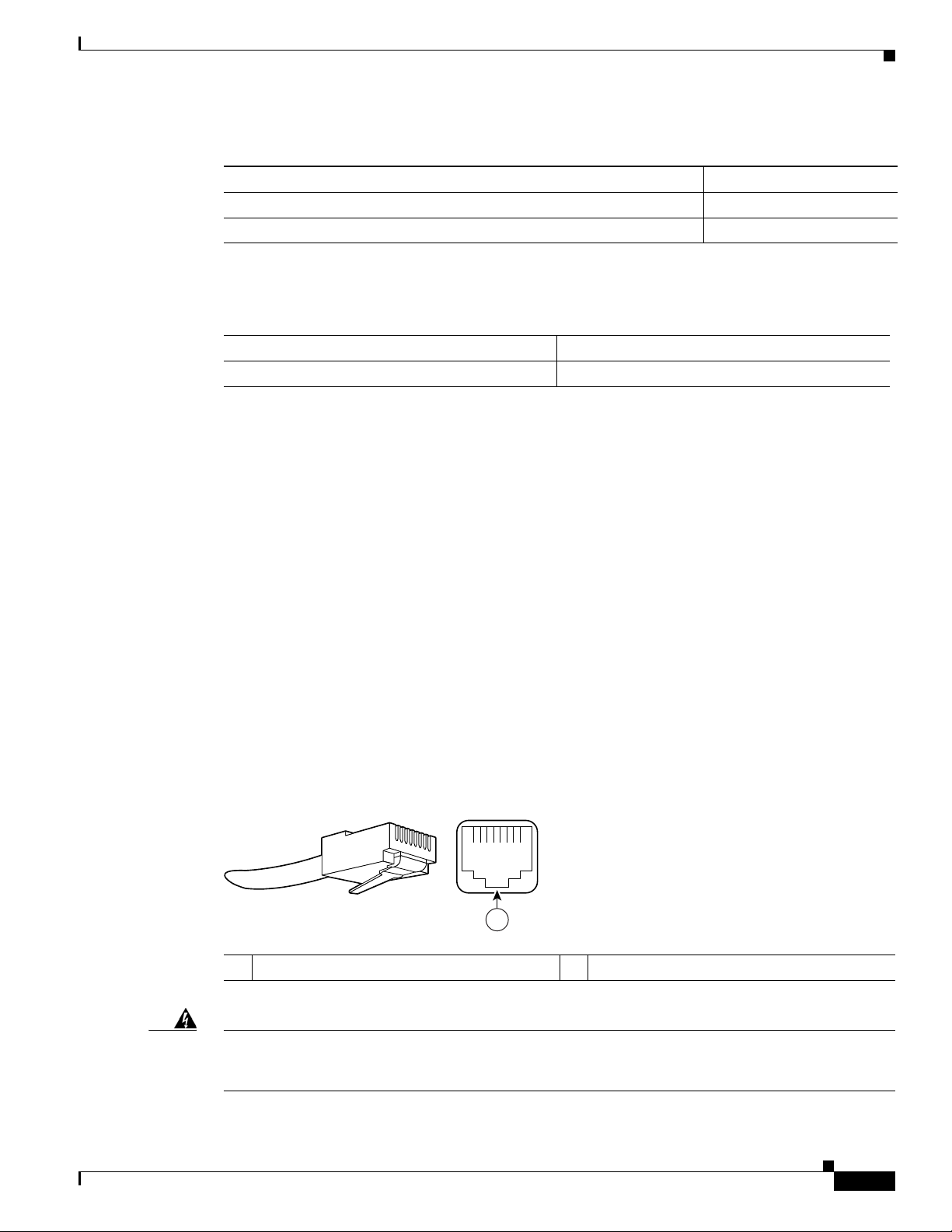
Chapter 6 NPE-G2 Overview
57574
12345678
1
Ta b l e 6-5 NPE-G2 USB Flash Memory Module Specifications
Token Size Product Number
64-MB USB Flash Token1 for Cisco 1800/2800/3800/7200
12-MB USB Flash Token for Cisco 1800/2800/3800/7200 MEMUSB-128FT=
1. Also known as flash memory modules.
Ta b l e 6-6 I/O Controller Blank Panel
Description Product Number
I/O Controller slot blank panel IO-CONTROLR-BLANK=
Connection Equipment and Specifications
This section contains connection equipment and pinout information for the Gigabit Ethernet RJ-45 ports,
Gigabit Ethernet SFP ports and SFP modules, Fast Ethernet Management port, console port, and
auxiliary port that are located on the NPE-G2.
NPE-G2 Memory Information and Specifications
MEMUSB-64FT=
Ethernet and Fast Ethernet RJ-45 Connection Equipment
The NPE-G2 has RJ-45 ports for Ethernet, Fast Ethernet, and Gigabit Ethernet or autosensing Ethernet,
Fast
Ethernet, and Gigabit Ethernet connections. The RJ-45 port supports IEEE 802.3 (Ethernet) and
IEEE
802.3u (Fast Ethernet) interfaces compliant with 10BASET, 100BASETX, and 1000BASET and
1000BASEX specifications.
The RJ-45 ports, including the Fast Ethernet Management port, support standard straight-through and
crossover Category 5 UTP cables with RJ-45 connectors. (See
Category 5 UTP cables; these cables are available commercially.
Figure 6-5 shows an RJ-45 port and connector. Tabl e 6-7 lists the pinouts and signals for the RJ-45 port.
Figure 6-5 RJ-45 Port and Connector
1 RJ-45 connector
Figure 6-5.) Cisco does not supply
OL-4448-12
Warning
To avoid electric shock, do not connect safety extra-low voltage (SELV) circuits to telephone-network
voltage (TNV) circuits. LAN ports contain SELV circuits, and WAN ports contain TNV circuits. Some
LAN and WAN ports both use RJ-45 connectors. Use caution when connecting cables.
Network Processing Engine and Network Services Engine Installation and Configuration
Statement 1021
6-13
Page 76

NPE-G2 Memory Information and Specifications
1 2
1 TPO+
2 TPO-
3 TP1+
6 TP1-
1 TP1+
2 TP1-
3 TPO+
6 TPO-
4 TP2+
5 TP2-
7 TP3+
8 TP3-
4 TP3+
5 TP3-
7 TP2+
8 TP2-
129086
Ta b l e 6-7 RJ-45 Port Pinouts
Pin 10/100 Signal Gigabit Ethernet Signal
1 Tx Data+
2 Tx Data– Tx A–
3 Rx Data+
4 N/C Tx C+
5 N/C Tx C–
6 Rx Data– Rx B–
7 N/C Rx D+
8 NC Rx D–
1. Tx Data = Transmit Data
2. Rx Data = Receive Data
Chapter 6 NPE-G2 Overview
1
2
Tx A+
Rx B+
Note With reference to the RJ-45 pinout in Tab l e 6-7, proper common-mode line terminations should be used
for the unused Category 5 UTP cable pairs 4/5 and 7/8. Common-mode termination reduces
electromagnetic interference (EMI).
Depending on your RJ-45 interface cabling requirements, use the pinouts shown in Figure 6-6 and
Figure 6-7 for Gigabit Ethernet straight-through and crossover twisted-pair cable connections. Use
Figure 6-8 for Ethernet/Fast Ethernet straight-through and crossover twisted-pair cable connections.
Figure 6-6 Four Twisted-Pair Straight-Through Cable Schematics for 10/100/1000 and
1000BASET SFP Module Ports
6-14
1 Router 2 Hub
Network Processing Engine and Network Services Engine Installation and Configuration
OL-4448-12
Page 77

Chapter 6 NPE-G2 Overview
1 TPO+
2 TPO-
3 TP1+
6 TP1-
1 TP0+
2 TP0-
3 TP1+
6 TP1-
4 TP2+
5 TP2-
7 TP3+
8 TP3-
4 TP2+
5 TP2-
7 TP3+
8 TP3-
129088
1 2
1 TxD+
2 TxD–
3 RxD+
6 RxD–
1 RxD+
2 RxD–
3 TxD+
6 TxD–
57607
1 TxD+
2 TxD–
3 RxD+
6 RxD–
1 TxD+
2 TxD–
3 RxD+
6 RxD–
1 2
3 34 5
Figure 6-7 Four Twisted-Pair Crossover Cable Schematics for 10/100/1000 and 1000BASET SFP
1 Router 2 Hub
Figure 6-8 Ethernet/Fast Ethernet Straight-Through and Crossover Cable Pinouts
NPE-G2 Memory Information and Specifications
Module Ports
1 Straight-through cable pinout, Ethernet port
to a hub or repeater
2 Crossover cable pinout, Ethernet port to a
DTE
3 Ethernet port
For information about straight-through and crossover cables, see the “Console and Auxiliary Port
Connection Equipment” section on page 6-20.
OL-4448-12
Network Processing Engine and Network Services Engine Installation and Configuration
4 Hub
5 DTE
6-15
Page 78

NPE-G2 Memory Information and Specifications
11772
CLASS 1 LASER PRODUCT
LASERPRODUKT DER KLASSE 1
PRODUIT LASER DE CLASSE 1
PRODUCTO LASER CLASE 1
RJ45
GIGABIT ETHERNET 0 / 1
EN
LINK
ACTV
RJ45
GIGABIT ETHERNET 0 / 2
EN
LINK
ACTV
149066
1
3
4
6
2
5
Gigabit Ethernet SFP Connection Equipment
The small for-factor pluggable (SFP) port is a 1000-Mbps optical interface in the form of an LC-type
duplex port that supports
IEEE 802.3z interfaces compliant with the 1000BASEX standard. (See Figure 6-10.)
Note The SFP module you ordered is shipped installed in the NPE-G2. Cisco sells individual SFP modules
separately and you can change the type of Gigabit Ethernet interface supported by this network
processing engine by simply changing its SFP module.
Chapter 6 NPE-G2 Overview
Warning
Warning
Because invisible laser radiation may be emitted from the aperture of the port when no cable is
connected, avoid exposure to laser radiation and do not stare into open apertures.
Statement 70
Figure 6-9 shows the Class 1 warning label that appears on the Gigabit Ethernet optical ports.
Figure 6-9 Laser Class 1 Warning Label
Class 1 Laser Product.
Statement 1008
Figure 6-10 shows the duplex LC-type connectors on your multimode or single-mode optical fiber
cables. For simplex connectors, two cables are required, one cable for transmit (TX) and a second cable
for receive (RX). For duplex connectors, only one cable that has both TX and RX connectors is required.
You can use either simplex or duplex connectors to the SFP ports on the NPE-G2.
Figure 6-10 SFP Port Connections
6-16
1 To external 1000BASEX network 4 Gigabit Ethernet port 0/1
2 1 duplex connector (TX and RX) 5 RX (SFP port 0/1)
3 SFP module 6 TX (SFP port 0/1)
Network Processing Engine and Network Services Engine Installation and Configuration
OL-4448-12
Page 79

Chapter 6 NPE-G2 Overview
Table 6-8 provides SFP module specifications.
Ta b l e 6-8 SFP Module Specifications
Specification Description
Dimensions (H x W x D) Height: 0.33 in. (8.5 mm)
Connectors Multimode fiber-optic: LC
The NPE-G2 supports single Gigabit Ethernet interfaces based on SFP technology. The following SFP
modules are supported by the NPE-G2:
• 100BASE-FX SFP—The SFP-GE-F=, 100BASE-FX SFP module is a hot-swappable device that
• 1000BASE-LX/LH SFP—The SFP-GE-L=, 1000BASE-LX/LH SFP module operates on ordinary
NPE-G2 Memory Information and Specifications
Depth: 0.53 in. (13.4 mm)
Width: 2.22 in. (56.5 mm)
Single-mode fiber-optic: LC
plugs into a Gigabit Ethernet SFP port. It provides full-duplex 100-Mbps connectivity between
switches over multimode fiber (MMF) infrastructures. The 100BASE-FX SFP operates on ordinary
MMF optical link spans of up to 6562 ft (2 km) in length. Customers implementing Cisco
100BASE-FX SFP can use 1000BASE-X SFP modules in the future (including SX, LH/LX, ZX, and
coarse wavelength-division multiplexing SFP modules).
single-mode fiber-optic link spans of up to 32,808 ft (10,000 m) in length.
• 1000BASE-SX SFP—The SFP-GE-S=, 1000BASE-SX SFP module operates on ordinary
multimode fiber-optic link spans of up to 1804 ft (550 m) in length.
• 1000BASE-ZX SFP—The SFP-GE-Z=, 1000BASE-ZX SFP module operates on ordinary single
mode fiber-optic link spans of up to 43.5 miles (70 km) in length. Link spans of up to 62.1 miles
(100 km) are possible using premium single-mode fiber or dispersion-shifted single-mode fiber. The
SFP module provides an optical link budget of 23 dB—the precise link span length depends on
multiple factors such as fiber quality, number of splices, and connectors.
When shorter distances of single-mode fiber are used, it may be necessary to insert an inline optical
attenuator in the link to avoid overloading the receiver. A 5-decibel (dB) or 10-dB inline optical
attenuator should be inserted between the fiber-optic cable plant and the receiving port on the
SFP-GE-Z= at each end of the link whenever the fiber-optic cable span is less than 15.5 miles (25
km).
Note Optical fiber cables are commercially available; they are not available from Cisco.
Note We strongly recommend cleaning optical fiber connections before attaching cables to equipment. See the
“Fiber Optic Cleaning Information” section on page 6-23 for information.
OL-4448-12
Network Processing Engine and Network Services Engine Installation and Configuration
6-17
Page 80

NPE-G2 Memory Information and Specifications
Table 6-9 provides SFP port cabling specifications.
Ta b l e 6-9 SFP Port Cabling Specifications
SFP Module
100BASE-FX
SFP-GE-F=
1000BASE-LX/LH
SFP-GE-L=
1000BASE-SX
SFP-GE-S=
1000BASE-ZX
SFP-GE-Z=
1. A mode-conditioning patch cord is required. Using an ordinary patch cord with MMF, 1000BASE-LX/LH SFP modules, and
a short link distance (tens of meters) can cause transceiver saturation resulting in an elevated bit error rate (BER). In addition,
when using the LX/LH SFP module with 62.5-micron diameter MMF, you must install a mode-conditioning patch cord
between the SFP module and the MMF cable on both the transmit and receive ends of the link. The mode-conditioning patch
cord is required for link distances greater than 984 ft (300 m).
Chapter 6 NPE-G2 Overview
Modal
Wavelength
(nm) Fiber Type
1270
MMF 62.5
1300
1380
Core Size
(microns)
2.5
50.0
50.0
1300 MMF1
SMF
62.5
50.0
50.0
9/10
850 MMF 62.5
62.5
50.0
50.0
1550 SMF 9/10 — 43.5 miles (70 km)
Bandwidth
(MHz/km) Cable Distance
500 6562 ft (2 km)
500
400
500
—
160
200
400
500
1804 ft (550 m)
1804 ft (550 m)
1804 ft (550 m)
6.2 miles (10 km)
722 ft (220 m)
902 ft (275 m)
1640 ft (500 m)
1804 ft (550 m)
Table 6-10 provides SFP module power budget information.
Ta b l e 6-10 SFP Module Transmit Power, Receive Power, and Power Budget
SFP Module Transmit Power Receive Power Power Budget
Minimum Maximum Minimum Maximum
SFP-GE-F= -23.5 dBm1
-20 dBm
SFP-GE-L= –9.5 dBm
2
3
–11.5dBm
SFP-GE-S= –9.5 dBm
8
4
-14 dBm1
-14 dBm
–3 dBm
–4 dBm
5
8
2
-33.5 dBm1
-33.5 dBm
2
-11.8 dBm1
-11.8 dBm
2
10 dBm1
13.5 dBm
–20 dBm –3 dBm 7.5 dBm6 and 8.0
dBm
–17 dBm 0 dBm 7.5 dBm
2
7
9
SFP-GE-Z= 0 dBm 5 dBm –23 dBm 0 dBm –24 dBm
1. For fiber type 50/125 mm SMF
2. For fiber type 62.5/125 mm SMF
3. For fiber types 9/125 μm SMF.
4. For fiber types 62.5/125 μm MMF and 50/125 μm MMF.
5. For fiber types 9/125 μm SMF, 62.5/125 μm MMF, and 50/125 μm MMF.
6. For fiber types 50/125 μm MMF and 62.5/125 μm MMF.
7. For fiber type 10 μm SMF.
8. For fiber types 50/125 μm, NA = 0.20 fiber and 62.5/125 μm, NA = 0.275 fiber.
9. For fiber types 50/125 μm MMF and 62.5/125 μm MMF.
6-18
Network Processing Engine and Network Services Engine Installation and Configuration
OL-4448-12
Page 81

Chapter 6 NPE-G2 Overview
Table 6-11 provides CWDM SFP module option information for the NPE-G2.
Ta b l e 6-11 CWDM SFP Module Options
Product Number Color
CWDM-SFP-1470 Gray
CWDM-SFP-1490 Violet
CWDM-SFP-1510 Blue
CWDM-SFP-1530 Green
CWDM-SFP-1550 Yel lo w
CWDM-SFP-1570 Orange
CWDM-SFP-1590 Red
CWDM-SFP-1610 Brown
Mode-Conditioning Patch Cord Description
NPE-G2 Memory Information and Specifications
A mode-conditioning patch cord can be used with the SFP-GE-L= (SFP module) to allow reliable laser
transmission between the single-mode laser source on the SFP module and a multimode optical fiber
cable.
When an unconditioned laser source designed for operation on single-mode optical fiber is directly
coupled to a multimode optical fiber cable, an effect known as differential mode delay (DMD) might
result in a degradation of the modal bandwidth of the optical fiber cable.
This degradation results in a decrease in the link span (the distance between a transmitter and a receiver)
that can be supported reliably. The effect of DMD can be overcome by conditioning the launch
characteristics of a laser source. A practical means of performing this conditioning is to use a device
called a mode-conditioning patch cord.
A mode-conditioning patch cord is an optical fiber cable assembly that consists of a pair of optical fibers
terminated with connector hardware. Specifically, the mode-conditioning patch cord is composed of a
single-mode optical fiber permanently coupled off-center (see Offset in
Figure 6-11) to a graded-index
multimode optical fiber. Figure 6-11 shows a diagram of the mode-conditioning patch cord assembly.
OL-4448-12
Network Processing Engine and Network Services Engine Installation and Configuration
6-19
Page 82

NPE-G2 Memory Information and Specifications
/ / / /
/ /
TX
Offset
RX
84159
1 7
2
3 7
4
8
65 4
Figure 6-11 Mode-Conditioning Patch Cord for an SFP Module
1 Gray color identifier 5 Single-mode fiber
2 To Gigabit Ethernet interface 6 Offset
3 Blue color identifier 7 Beige color identifier
4 Multimode fiber 8 To cable plant
Chapter 6 NPE-G2 Overview
The mode-conditioning patch cord assembly is composed of duplex optical fibers, including a
single-mode-to-multimode offset launch fiber connected to the transmitter, and a second conventional
graded-index multimode optical fiber connected to the receiver. The use of a plug-to-plug patch cord
maximizes the power budget of multimode 1000BASE LX and 1000BASE LH links.
The mode-conditioning patch cord is required to comply with IEEE standards. The IEEE found that link
distances could not be met with certain types of fiber-optic cable cores. The solution is to launch light
from the laser at a precise offset from the center, which is accomplished by using the mode-conditioning
patch cord. At the output of the patch cord, the SFP-GE-L= is compliant with the IEEE 802.3z standard
for 1000BASE LX.
Console and Auxiliary Port Connection Equipment
The NPE-G2 has a DCE-mode console port for connecting a console terminal, and a DTE-mode
auxiliary port for connecting a modem or other DCE device (such as a CSU/DSU or other router) to your
router. However, with an I/O controller also installed in the router, the default console and auxiliary ports
are on the I/O controller, and you cannot access the console and auxiliary ports on the NPE-G2.
Note Both the console and the auxiliary ports are asynchronous serial ports; any devices connected to these
ports must be capable of asynchronous transmission. (Asynchronous is the most common type of serial
device; for example, most modems are asynchronous devices.)
The NPE-G2 uses RJ-45 media for console port and auxiliary port connections.
Before connecting a terminal to the console port, configure the terminal to match the router console port
as follows: 9600 baud, 8 data bits, no parity, 2 stop bits (9600 8N2). After you establish normal router
operation, you can disconnect the terminal.
Network Processing Engine and Network Services Engine Installation and Configuration
6-20
OL-4448-12
Page 83

Chapter 6 NPE-G2 Overview
Pin 1
Pin 8
H3824
Pin 1 and pin 8
should be the
same color
Note When connecting to an auxiliary port on a Cisco 7200 VXR router, the port will not function at baud
Refer to Tab le 6-13 for a list of the pins used on the RJ-45-to-DB-25 adapters, used with an RJ-45 cable,
to connect terminals and modems to the Cisco 7200 series routers. The cable you use may be a roll-over
cable or a straight cable.
Ta b l e 6-12 Pinouts for the RJ-45-to-DB-25 Adapters
NPE-G2 Memory Information and Specifications
rates higher than 19.2k. If the baud rate on the connecting device is set higher than 19.2k, either
garbled text or nothing will be displayed on the screen.
Adapter DTE M/F Pins
1
DCE M/F Pins MMOD Pins
2
1 4 5 5
2 20 6 8
3 2 3 3
4 7 7 7
5 7 7 7
6 3 2 2
7 6 20 20
8 5 4 4
1. The female data terminal equipment (FDTE) adapter that is available from Cisco is labeled “Terminal”.
2. The MMOD adapter that is available from Cisco is labeled “Modem”.
A roll-over cable can be detected by comparing the two modular ends of the cable. Holding the cables
in your hand, side-by-side, with the tab at the back, the wire connected to the pin on the outside of the
left plug should be the same color as the pin on the outside of the right plug. If your cable was purchased
from Cisco, pin 1 will be white on one connector, and pin 8 will be white on the other (a roll-over cable
reverses pins 1 and 8, 2 and 7, 3 and 6, and 4 and 5). (See
Figure 6-12 Identifying a Roll-Over Cable
Figure 6-12.)
OL-4448-12
Network Processing Engine and Network Services Engine Installation and Configuration
6-21
Page 84

NPE-G2 Memory Information and Specifications
3
4
5
CONSOLE AUX
FE 0/2
FOR MANAGEMENT
USE ONLY
USB
CF
ACTV
U
S
B
NETWORK PROCESSING ENGINE - G2
COMPACT FLASH
FE
LINK
PWR
OK
SYST
STAT
1
2
The Cisco 7200 series routers ship with a roll-over cable. Connection to a terminal or a modem requires
an RJ-45-to-DB-25 adapter, and possibly a DB-25-to-DB9 adapter. Refer to
adapter configurations that can be used to connect terminals and modems to the Cisco 7200 series
routers.
Ta b l e 6-13 Asynchronous Device Cabling Options
Access Server Port RJ-45 Cable Type DB-25 Adapter End Device
Console or auxiliary Roll-over FDTE
Console or auxiliary Straight FDCE Term i n a l
Auxiliary or console Roll-over MMOD
1. The FDTE RJ-45-to-DB-25 adapter is labeled “Terminal.”
2. The MMOD RJ-45-to-DB-25 adapter is labeled “Modem.”
The console and auxiliary ports are configured as asynchronous serial ports. Figure 6-13 shows the
RJ-45 console and auxiliary port connections.
Figure 6-13 Console and Auxiliary Port RJ-45 Connections
Chapter 6 NPE-G2 Overview
Table 6-13 for the cable and
1
2
Ter m i n a l
Modem
1 Console port 4 Cable to console terminal or DTE
2 Auxiliary port 5 Cable to modem or DCE
3 RJ-45 connectors
A cable and adapter kit is available from Cisco (Cisco Product Number ACS-2500ASYN=). Table 6-12
describes the cable and adapter configurations that can be used to connect terminals and modems to the
console or the auxiliary port.
RJ-45 Console Port Signals and Pinouts
The NPE-G2 console port supports Data Carrier Detect (DCD). Tabl e 6-14 lists the RJ-45 console port
signals for the NPE-G2.
Network Processing Engine and Network Services Engine Installation and Configuration
6-22
OL-4448-12
Page 85

Chapter 6 NPE-G2 Overview
Ta b l e 6-14 Console Port Signals for the NPE-G2
1
Pin
Signal Direction Description
1 CTS Out Clear To Send (tracks RTS)
2 DSR Out Data Set Ready (always on)
3 RXD Out Receive Data
4 GND — Signal Ground
6 TXD In Transmit Data
7 DTR In Data Terminal Ready
8 RTS In Ready To Send
1. Any pin not referenced is not connected.
RJ-45 Auxiliary Port Signals and Pinouts
Table 6-15 lists the RJ-45 auxiliary port signals for the NPE-G2.
Ta b l e 6-15 Auxiliary Port Signals for the NPE-G2
Fiber Optic Cleaning Information
1
Pin
Signal Direction Description
1 RTS Out Ready To Send
2 DTR Out Data Terminal Ready
3 TXD Out Transmit Data
4 RING
2
In Ring Indication
5 GND — Signal Ground
6 RXD In Receive Data
3
7
DSR/DCD(RLSD) In Data Set Ready/Data Carrier Detect (Receive Line Signal
8 CTS In Clear To Send (tracks RTS)
1. Any pin not referenced is not connected.
2. RING is not supported on Cisco-supplied adapters. To use this pin, you must create a customized cable.
3. Pin 7 can be used as a DCD input for connection to a modem. The RJ-45-to-DB-25F adapter maps DCD to this pin when
used with a straight-through cable.
Fiber Optic Cleaning Information
We strongly recommend cleaning all optical fiber connections before reconnecting optical cables to
equipment. For information about cleaning optical connectors, see the
Procedures for Fiber-Optic Connections document and the Compressed Air Cleaning Issues for
Fiber-Optic Connections document.
Detect)
Inspection and Cleaning
OL-4448-12
Network Processing Engine and Network Services Engine Installation and Configuration
6-23
Page 86

Fiber Optic Cleaning Information
Chapter 6 NPE-G2 Overview
6-24
Network Processing Engine and Network Services Engine Installation and Configuration
OL-4448-12
Page 87

CHAP T ER
7
NPE-G1 and NPE-G2 Installation and Configuration Information
This chapter provides information on installing and configuring the NPE-G1 and NPE-G2 and contains
the following sections:
• Preparing for an Upgrade, page 7-2
• Copying the Configuration File, page 7-4
• Removing the Network Processing Engine, page 7-7
• Installing the NPE-G1 or NPE-G2, page 7-18
• Enabling the Second Processor on the NPE-G1, page 7-46
• Copying the Saved Configuration to NVRAM, page 7-52
• Auxiliary and Console Port Information, page 7-56
• Configuring the Native Gigabit Ethernet Interfaces, page 7-56
• Using show Commands to Check the Installation, page 7-59
• Upgrading the Cisco IOS Image and the Boot Helper (Boot Loader) Image, page 7-62
OL-4448-12
• Upgrading ROMmon on the NPE-G1 or NPE-G2, page 7-63
• Troubleshooting the Upgrade, page 7-65
• Upgrading FPGA on the NPE-G2, page 7-67
• Troubleshooting the NPE-G1 or NPE-G2, page 7-67
• Fiber Optic Cleaning Information, page 7-67
Note The Cisco 7200 VXR routers and Cisco uBR7200 series routers use different models of the NPE-G1 and
the NPE-G2 processors. For the Cisco
the Cisco
UBR7200-NPE-G2, or UBR7200-NPE-G2= product.
uBR7200 series routers, order the UBR7200-NPE-G1, UBR7200-NPE-G1=,
Network Processing Engine and Network Services Engine Installation and Configuration
7200 VXR routers, order the NPE-G1 or NPE-G1= product. For
7-1
Page 88

Preparing for an Upgrade
Tip Before you begin any removal or installation procedure, read Chapter 8, “Preparation for Installation.”
Also, for the NPE-G1, see the NPE-G1 Read Me First document, at the following URL:
http://www.cisco.com/en/US/products/hw/routers/ps341/prod_installation_guide09186a00805e396a.ht
ml
For the Cisco uBR7200-NPE-G1, see the Cisco uBR7200-NPE-G1 Read Me First document, at the
following URL:
http://www.cisco.com/en/US/products/hw/cable/ps2217/prod_pre_installation_guide09186a008017bde
6.html
Preparing for an Upgrade
Note Cisco IOS Release 12.2 changed the behavior of the ROM monitor (ROMmon) during the bootup
sequence. See the “Boot Changes in Cisco IOS Release 12.2” section on page 10-2 for more information.
Chapter 7 NPE-G1 and NPE-G2 Installation and Configuration Information
Upgrading to the NPE-G1 or NPE-G2 is a different procedure than previous processor upgrades because
of the following considerations:
• The NPE-G1 and NPE-G2 contain an I/O controller, which includes the bootflash and NVRAM
memory. After you install the NPE-G1 or NPE-G2 in a chassis, you can no longer access the
bootflash and NVRAM on the I/O controller. You therefore must make the existing Cisco
IOS
software image and configuration files available to the NPE-G1 or NPE-G2, either by putting these
files on a CompactFlash Disk or on a TFTP server.
• The NPE-G1 and NPE-G2 include three Gigabit Ethernet interfaces. If you want to use these
interfaces to replace the Ethernet or Fast Ethernet interfaces on the existing I/O controller, you must
configure the new interfaces before they can be used to access the network. If you are also removing
the existing I/O controller, you must remove the configuration for its Ethernet or Fast Ethernet
interfaces.
Note The NPE-G2 provides a Fast Ethernet Management port, as well as three RJ-45 Gigabit
Ethernet ports.
• The NPE-G1 and NPE-G2 use Type 1 CompactFlash Disk memory instead of the Type 2 Flash Disk
memory used in existing I/O controllers. You must transfer any information currently saved on Flash
Disks to CompactFlash Disks so that it can be used after the upgrade to the NPE-G1 or NPE-G2.
Note If you are upgrading to an NPE-G2 from an NPE-G1, you do not need to perform the following
procedure.
7-2
To ensure a smooth upgrade, perform the following procedure only if you are upgrading to an NPE-G1
or NPE-G2 from an NPE-400 or earlier network processing engine.
Network Processing Engine and Network Services Engine Installation and Configuration
OL-4448-12
Page 89

Chapter 7 NPE-G1 and NPE-G2 Installation and Configuration Information
Before you install an NPE-G1 or NPE-G2 in an existing router and remove the existing processor and
I/O controller, do the following:
Step 1 Copy the configuration file from the existing router to a TFTP server, Flash Disk, or PC Card. See the
“Copying the Configuration File” section on page 7-4 for details.
Step 2 Modify the configuration file to accommodate the new Gigabit Ethernet interfaces on the NPE-G1 or
NPE-G2. If you are also planning to remove the I/O controller, also remove the configuration lines for
the Ethernet or Fast Ethernet interfaces on the I/O controller. See the
Ethernet Interfaces” section on page 7-56 for guidelines.
Step 3 Copy the modified configuration file to a CompactFlash Disk that can be used on the NPE-G1 or
NPE-G2. If you are not planning on removing the existing I/O controller, you can do this by copying the
configuration to a Flash Disk, as described in
you can keep the Flash Disk in the I/O controller and copy it to a CompactFlash Disk in the NPE-G1 or
NPE-G2 after you have finished installing the NPE-G1 or NPE-G2.
If you are planning on removing the existing I/O controller, you can copy the configuration file to a
CompactFlash Disk in the following ways:
• Copy the configuration file to a TFTP server and then copy it to a CompactFlash Disk on an existing
NPE-G1 or NPE-G2.
Preparing for an Upgrade
“Configuring the Native Gigabit
Step 1, before you install the NPE-G1 or NPE-G2. Then
• Copy the configuration file to a Type 2 Flash Disk using the existing I/O controller, as described in
the
“Copying the Configuration File to a Flash Disk or PC Card” section on page 7-4. Then use a
multi-function reader that accommodates both Type 1 CompactFlash Disk and Type 2 Flash Disk
memory cards to transfer the configuration file to the CompactFlash Disk.
• Use a Type 1-to-Type 2 adapter to convert the CompactFlash Disk to the Flash Disk form factor.
Then insert the CompactFlash Disk and adapter into the existing I/O controller and copy the
configuration file to it, as described in
Note The CompactFlash Disk must be formatted before you can write any files to it. The
Step 1.
CompactFlash Disk shipped with the NPE-G1 or NPE-G2 is already formatted, but a spare
CompactFlash Disk must be formatted using the format command. Do not format the
CompactFlash Disk in a PC or other workstation because the router cannot use CompactFlash
Disks that are formatted by other computers. After the CompactFlash Disk is properly formatted,
however, you can write to it using any PC or workstation that recognizes Type 2 CompactFlash
Disk memory.
Step 4 (Optional) Copy the proper Cisco IOS software image (see Ta ble 8-4 on page 8-4) to the CompactFlash
Disk, using the same technique you used to copy the configuration file in Step 3. You do not need to
perform this step if you plan to boot the router from a TFTP server, but you must add the proper boot
configuration command to the configuration file when you modify it in
Step 2.
OL-4448-12
Network Processing Engine and Network Services Engine Installation and Configuration
7-3
Page 90

Copying the Configuration File
Copying the Configuration File
Caution Before powering down the router to install the NPE-G1 or NPE-G2, you must save the current
configuration to a Flash Disk, PC Card, Trivial
you install the NPE-G1 or NPE-G2, or the configuration will be lost and you will have to manually
re-enter your configuration.
Cisco IOS looks to the NPE-G1 or NPE-G2 NVRAM for the startup running configuration, because the
NPE-G1 or NPE-G2, by default, stores the running configuration, whether or not an I/O controller is
installed with the NPE-G1 or NPE-G2.
The following sections provide instructions for copying the file to a Flash Disk, PC Card, or TFTP
server, and for copying it manually using a terminal program on a PC:
• Copying the Configuration File to a Flash Disk or PC Card, page 7-4
• Copying the Configuration File to a TFTP Server, page 7-5
• Copying the Configuration File Using a PC, page 7-7
Chapter 7 NPE-G1 and NPE-G2 Installation and Configuration Information
File Transfer Protocol (TFTP) file server, or PC before
Copying the Configuration File to a Flash Disk or PC Card
Use the following instructions for copying the router configuration file to a Flash Disk or PC Card.
Caution If the NPE-G1 or NPE-G2 will be installed in a router with either a C7200-I/O-GE/E or
C7200-I/O-2FE/E I/O controller, copy your running configuration to a Flash Disk, not a PC Card. PC
Cards are not supported on these I/O controllers when an NPE-G1 or NPE-G2 is present. If you copy the
running configuration to a PC Card with these I/O controllers present, you will not be able to retrieve
the running configuration after the NPE-G1 or NPE-G2 is installed.
Step 1 Insert the Flash Disk or PC Card into I/O controller PC Card slot 0. If slot 0 is full, use slot 1. If you
need to format the Flash Disk, go to Step 2. If the Flash Disk is already formatted, go to
Step 2 Use the format disk0: command to format a Flash Disk in slot 0. Use the format disk1: command to
format a Flash Disk in slot 1. If you are using a PC card, use slot0 or slot1 as part of the command.
System# format disk0:
Format operation may take a while. Contineu: [confirm]
Format operation will destroy all data in ‘disk0:’. Continue? [confirm]
Format :Drive communication and 1st Sector Write OK...
Writing Monlib sectors
..........................................................................................
Monlib write complete
Format:All system sectors written. OK...
Format:Total sectors in formatted partitioin:81760
Format:Total bytes in formatted partition:49861120
Format:Operation completed successfully.
Step 3.
7-4
Format of disk0:complete
The Flash Disk is now formatted and ready to use in the system on which you formatted it.
Network Processing Engine and Network Services Engine Installation and Configuration
OL-4448-12
Page 91

Chapter 7 NPE-G1 and NPE-G2 Installation and Configuration Information
Step 3 Make sure you are at the privileged level of the EXEC command interpreter (check the system prompt
for a pound sign [#]). If the system prompt does not have a pound sign (#), enter enable, and then your
password.
Step 4 Enter the show running-config command to display the router’s running configuration. Ensure that the
configuration information is complete and correct. If it is not, use the configure command to add or
modify the existing configuration. Then enter the copy
Disk 0 or 1, use disk0 or disk1 as part of the command. If you are using a PC Card, use slot0 or slot1
as part of the command.
Step 5 To copy the running configuration file to the Flash Disk or PC Card, enter the copy running-config
disk0: filename or copy running-config slot0: filename command:
System# copy running-config disk0: filename
You have finished copying the running configuration file to the Flash Disk or PC Card.
Go to the “Removing the Network Processing Engine” section on page 7-7 for instructions on removing
the current network processing engine or network services engine and replacing it with the NPE-G1 or
NPE-G2.
Copying the Configuration File
running-config command. If you have a Flash
Copying the Configuration File to a TFTP Server
Before copying the router configuration file to a TFTP file server, check the following items:
• A console terminal is connected to the console port on the I/O controller or a Telnet session is
established to the router.
• The router is connected to a network supporting a file server (remote host).
• The remote host supports the TFTP application.
• You have the name or address of the remote host.
Complete the following steps to copy the router’s configuration file to a remote host:
Step 1 Make sure you are at the privileged level of the EXEC command interpreter (check the system prompt
for a pound sign [#]). If the system prompt does not have a pound sign (#), enter enable, and then your
password.
Step 2 Use the ping command to check the connection between the router and the remote host.
Step 3 Enter the show running-config command to display the router’s running configuration. Ensure that the
configuration information is complete and correct. If it is not, use the configure command to add or
modify the existing configuration. Then enter the copy
save the retrieved configuration in NVRAM. NVRAM uses lithium batteries to maintain its contents
when disconnected from power.
running-config startup-config command to
OL-4448-12
Note Refer to the appropriate software documentation listed in the “Related Documentation” section
on page iii for descriptions of the configuration options available for the system and individual
interfaces, and for specific configuration instructions.
Network Processing Engine and Network Services Engine Installation and Configuration
7-5
Page 92

Copying the Configuration File
Step 4 Enter the copy startup-config tftp command. The EXEC command interpreter prompts you for the
name or IP address of the remote host that is to receive the configuration file. (The prompt might
include the name or address of a default file server.)
Router# copy startup-config tftp
Remote host []?
Step 5 Enter the name or IP address of the remote host. In the following example, the name of the remote host
is servername:
Router# copy startup-config tftp
Remote host []? servername
Translating "servername"...domain server (10.1.1.1) [OK]
Step 6 The EXEC command interpreter prompts you for the name of the file that will contain the configuration.
By default, the system appends -confg to the router’s name to create the new filename. Press Return to
accept the default filename, or enter a different name for the file before pressing Return. In the following
example, the default is accepted:
Name of configuration file to write [Router-confg]?
Write file Router-confg on host 10.1.1.1? [confirm]
Writing Router-confg.....
Chapter 7 NPE-G1 and NPE-G2 Installation and Configuration Information
Step 7 Before the router executes the copy process, it displays the instructions you entered for confirmation. If
the instructions are not correct, enter n (no), and then press Return to stop the process. To accept the
instructions, press Return, or y and then press Return; the system begins the copy process. In the
following example, the default is accepted:
Write file Router-confg on host 10.1.1.1? [confirm]
Writing Router-confg: !!!! [ok]
While the router copies the configuration to the remote host, it displays a series of exclamation points
(!
! !) or periods (. . .). The !!!! and [ok] indicate that the operation is successful. A display of . . . [timed
out] or [failed] indicates a failure, which would probably be because of a network fault or the lack of a
writable, readable file on the remote file server.
Step 8 Check the result of the copy process.
• If the display indicates that the process was successful (with the series of exclamation points [! ! !]
and [ok]), the copy process is complete. The configuration file is safely stored in the temporary file
on the remote file
• If the display indicates that the process failed (with the series of periods [. . .] as shown in the
server.
following example), your configuration was not saved:
Writing Router-confg .....
Step 9 If your configuration was not saved, repeat the preceding steps, or select a different remote file server
and repeat the preceding steps. If you are unable to copy the configuration to a remote host
successfully, contact your network administrator or see the
“Obtaining Documentation and Submitting
a Service Request” section on page iv for instructions on contacting technical assistance.
7-6
This completes the procedure for copying the configuration file to a TFTP server. Proceed to “Removing
the Network Processing Engine” section on page 7-7.
Network Processing Engine and Network Services Engine Installation and Configuration
OL-4448-12
Page 93

Chapter 7 NPE-G1 and NPE-G2 Installation and Configuration Information
Copying the Configuration File Using a PC
Complete the following steps to copy the router’s configuration file to a text file on a PC connected to
the router’s console port.
Step 1 Connect a serial port on the PC to the router’s console port. Start a terminal program on the PC and
configure it for the same baud rate, parity, and stop-bits that the console port is using.
Step 2 Turn on the terminal program’s capture buffer so that it will save all output to a text file.
Step 3 Enter the show startup-config command in privileged EXEC mode to display the router’s startup
configuration.
Note Refer to the appropriate software documentation listed in the “Related Documentation” section
on page iii for descriptions of the configuration options available for the system and individual
interfaces, and for specific configuration instructions.
Step 4 When the router has completed displaying the configuration, turn off the terminal program’s capture
buffer and save the configuration file to the disk on the PC.
Step 5 (Optional) Use a text editor on the PC to modify the configuration, as needed.
Removing the Network Processing Engine
This completes the procedure for copying the configuration file to a PC. Proceed to “Removing the
Network Processing Engine” section on page 7-7.
Removing the Network Processing Engine
Before you begin any removal or installation procedure, read Chapter 8, “Preparation for Installation.”
To install the NPE-G1 or NPE-G2, follow the instructions in this chapter for removal of an existing
network processing engine or network services engine and installation of the NPE-G1 or NPE-G2.
Note If you are removing the I/O controller, and do not plan to replace it, you must install an I/O controller
blank panel (Cisco Product Number IO-CONTROLR-BLANK=) in the I/O controller slot. See the
Input/Output Controller Replacement Instructions for information on removing an I/O controller and
installing an I/O controller blank panel.
If you are installing a Port Adapter Jacket Card, see the Port Adapter Jacket Card Installation Guide for
installation information.
OL-4448-12
Network Processing Engine and Network Services Engine Installation and Configuration
7-7
Page 94

Removing the Network Processing Engine
Ensuring Easy Access to the Router
If your Cisco 7200 VXR router or Cisco uBR7200 series router is installed in a standard 19-inch, 4-post
or telco-type rack, cables from other equipment in the rack might obstruct access to the rear of the router.
Also, rack power strips or other permanent fixtures may obstruct access to the router. Review the
following guidelines to ensure easy access to the rear of the router when it is installed in a rack. This is
particularly important because the NPE-G1 and NPE-G2 have interfaces that require cabling on the rear
of the router.
If the router is not installed in a rack, or if you already have clear access to the rear of the router, proceed
to the
“Powering Down the Router and Disconnecting Input Power” section on page 7-8.
Use the following guidelines to ensure easy access to the rear of the router when it is installed in a rack:
• Ensure that you have at least 3 to 4 feet (0.91 to 1.22 meters) of working space at the rear of the
router.
• If cables from other equipment in the rack fall in front of the rear end of the router, carefully gather
the cables (using care not to strain or stress them) and use cable ties to anchor them away from the
rear of the router.
• If access to the rear of the router is partially blocked by a power strip or some other permanent rack
fixture, detach the router from the rack and carefully slide it forward until there is enough clearance
to remove the power supply, the network processing engine, and the subchassis from the router.
Chapter 7 NPE-G1 and NPE-G2 Installation and Configuration Information
Caution Make sure that at least one other person is available to support the front of the router as you slide it out
from the rack and, if necessary, to continue to support it while you remove and insert the power supply,
network processing engine, or subchassis.
Powering Down the Router and Disconnecting Input Power
Complete the steps in the following sections to power down the router and disconnect input power.
Warning
Powering Down the Router
Note Before powering down the router, use the copy running-config startup-config command to save the
This unit might have more than one power cord. To reduce the risk of electric shock, disconnect the
two power cords before servicing. Statement 83
To power down a Cisco 7200 VXR router or Cisco uBR7200 series router, complete the following steps:
router’s running configuration to a Flash Disk, PC Card, TFTP server, or PC. If you do not, you will have
to manually re-enter the configuration after you install the NPE-G1 or NPE-G2 and power on the router.
See the “Copying the Configuration File” section on page 7-4.
7-8
Step 1 Facing the rear of the router, place the power switch on the power supply in the off (O) position. Repeat
this action if a second power supply is installed in the router.
Network Processing Engine and Network Services Engine Installation and Configuration
OL-4448-12
Page 95

Chapter 7 NPE-G1 and NPE-G2 Installation and Configuration Information
Note When powering off the router, wait a minimum of 30 seconds before powering it on again.
Step 2 Observe the following items:
• The green OK LED on the power supply turns off.
• The fans stop operating.
• The LEDs on the I/O controller turn off.
• The LEDs on the port adapters turn off.
Caution When the power switch on a Cisco uBR7200 series power supply is turned to the off (O) position, the
power supply enters a reset cycle for 90 seconds. Wait at least 90 seconds before turning the power
switch back to the on (|) position. If you do not wait the full 90 seconds, the power supply does not
restart.
Removing the Network Processing Engine
This completes the procedure for powering down the router. The following sections provide instructions
on disconnecting power from the Cisco 7200 VXR routers and Cisco uBR7200 series routers:
• Disconnecting AC-Input Power from a Cisco 7200 VXR Router, page 7-9
• Disconnecting AC-Input Power from a Cisco uBR7246VXR Router, page 7-10
• Disconnecting AC-Input Power from a Cisco uBR7225VXR Router, page 7-11
• Disconnecting DC-Input Power from a Cisco 7200 VXR Router, page 7-11
• Disconnecting DC-Input Power from a Cisco uBR7246VXR Router, page 7-13
Disconnecting AC-Input Power from a Cisco 7200 VXR Router
To disconnect AC-input power from a Cisco 7200 VXR router, complete the following steps:
Step 1 Unplug the input power cable from the power source.
Step 2 Push up on the cable-retention clip that secures the input power cable to the router power supply.
Step 3 Unplug the other end of the input power cable from the power supply. See Figure 7-1.
OL-4448-12
Network Processing Engine and Network Services Engine Installation and Configuration
7-9
Page 96
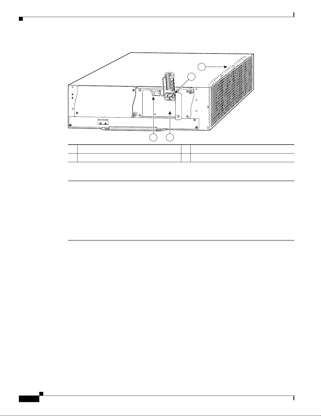
Removing the Network Processing Engine
NETW
ORK PROCESSING ENGINE
-300
66415
3
2
4
1
Figure 7-1 Disconnecting Power from a Cisco 7200 VXR Router AC-Input Power Supply
1 AC-input receptacle 3 Power switch
2 Internal fans 4 AC-input power supply
Chapter 7 NPE-G1 and NPE-G2 Installation and Configuration Information
Step 4 Repeat Step 1 through Step 3 if a second power supply is installed.
This completes the procedure for disconnecting AC-input power from a Cisco 7200 VXR router. Go to
the
“Removing the NPE or NSE-1” section on page 7-16.
Disconnecting AC-Input Power from a Cisco uBR7246VXR Router
To disconnect AC-input power from a Cisco uBR7246VXR router, complete the following steps:
Step 1 Unplug the input power cable from the power source.
Step 2 Push the cable-retention clip that secures the input power cable to the router power supply to the left.
Step 3 Unplug the other end of the input power cable from the power supply. See Figure 7-2.
7-10
Network Processing Engine and Network Services Engine Installation and Configuration
OL-4448-12
Page 97

Chapter 7 NPE-G1 and NPE-G2 Installation and Configuration Information
66434
3
4
21
5
Figure 7-2 Disconnecting Power from a Cisco uBR7246VXR AC-Input Power Supply
Removing the Network Processing Engine
1 AC-input receptacle 4 Network processing engine
2 Power switch 5 AC-input power supply
3 Handle
Step 4 Repeat Step 1 through Step 3 if a second power supply is installed.
This completes the procedure for disconnecting AC-input power from a Cisco uBR7246VXR router. Go
to the
“Removing the NPE or NSE-1” section on page 7-16.
Disconnecting AC-Input Power from a Cisco uBR7225VXR Router
To disconnect AC-input power from a Cisco uBR7225VXR router, complete the following steps:
Step 1 Unplug the input power cable from the power source.
Step 2 Unplug the other end of the input power cable from the power supply.
Note The Cisco uBR7225VXR router power supply does not have a cable retention-clip.
Disconnecting DC-Input Power from a Cisco 7200 VXR Router
To disconnect DC-input power from a Cisco 7200 VXR router, complete the following steps.
Network Processing Engine and Network Services Engine Installation and Configuration
OL-4448-12
7-11
Page 98

Removing the Network Processing Engine
66431
networking xxxx engine
1 2
3 4
Chapter 7 NPE-G1 and NPE-G2 Installation and Configuration Information
Warning
Before completing any of the following steps, and to prevent short-circuit or shock hazards, ensure
that power is removed from the DC circuit. To ensure that all power is OFF, locate the circuit breaker
on the panel board that services the DC circuit, switch the circuit breaker to the OFF position, and
Warning
tape the switch handle of the circuit breaker in the OFF position.
When you install the unit, the ground connection must always be made first and disconnected last.
Statement 332
Statement 42
Step 1 At the rear of the router, check that the power switch on the power supply is in the off (O) position. (For
the Cisco
Step 2 Ensure that no current is running through the –V and +V leads. To ensure that all power is off, locate the
7200 VXR routers, see Figure 7-3.)
circuit breaker on the panel board that services the DC circuit, switch the circuit breaker to the off
position, and tape the switch handle of the circuit breaker in the off position.
Step 3 Disconnect the –V and +V leads. You can leave the ground cable connected.
For a Cisco 7200 VXR router, remove the cable tie that secures the –V, +V, and ground leads to the power
supply faceplate. Save the cable tie.
Note The cable tie that accompanied your Cisco 7200 VXR router DC-input power supply can be
removed and replaced on the power supply without the use of a tool. If you secured the DC-input
power supply leads to the power supply faceplate using a different type of cable tie, use a wire
stripper to cut that cable tie from the power supply.
Figure 7-3 Disconnecting Power from a Cisco 7200 VXR Router DC-Input Power Supply
1 DC-input receptacle 3 Power switch
2 Internal fans 4 DC-input power supply
Step 4 Using a 3/16-inch flat-blade screwdriver, loosen the screw below the +V lead receptacle and pull the lead
from the connector. See
Figure 7-3.
7-12
Network Processing Engine and Network Services Engine Installation and Configuration
OL-4448-12
Page 99

Chapter 7 NPE-G1 and NPE-G2 Installation and Configuration Information
Step 5 Repeat this step for the –V lead and the ground lead.
Note The color coding of the DC-input power supply leads depends on the color coding of the DC
power source at your site. Typically, green or green and yellow are used for ground. Make certain
that the lead color coding you choose for the DC-input power supply matches the lead color
coding used at the DC power source.
Step 6 Repeat Step 1 through Step 6 if a second power supply is installed.
This completes the procedure for disconnecting DC-input power from a Cisco 7200 VXR router. Go to
the
“Removing the NPE or NSE-1” section on page 7-16.
Disconnecting DC-Input Power from a Cisco uBR7246VXR Router
To disconnect DC-input power from a Cisco uBR7246VXR router, complete the following steps.
Removing the Network Processing Engine
Warning
Warning
Step 1 At the rear of the router, check that the power switch on the power supply is in the off (O) position.
Step 2 Ensure that no current is running through the –V and +V leads. To ensure that all power is off, locate the
Before completing any of the following steps, and to prevent short-circuit or shock hazards, ensure
that power is removed from the DC circuit. To ensure that all power is OFF, locate the circuit breaker
on the panel board that services the DC circuit, switch the circuit breaker to the OFF position, and
tape the switch handle of the circuit breaker in the OFF position.
When you install the unit, the ground connection must always be made first and disconnected last.
Statement 42
Statement 322
circuit breaker on the panel board that services the DC circuit, switch the circuit breaker to the off
position, and tape the switch handle of the circuit breaker in the off position.
Step 3 Use a 7-mm wrench or nut driver (or adjustable wrench) to loosen and remove the two M4 nuts from the
strain-relief cover that secures the –V and the +V leads to the power supply faceplate. See
Figure 7-4.
OL-4448-12
Network Processing Engine and Network Services Engine Installation and Configuration
7-13
Page 100

Removing the Network Processing Engine
66408
3
5
7
6
8
1
2
9
4
Figure 7-4 Removing the Strain-Relief Cover from a Cisco uBR7246VXR Router DC-Input Power
Chapter 7 NPE-G1 and NPE-G2 Installation and Configuration Information
Supply
1 Power switch 6 –V lead
2 Power receptacle 7 +V lead
3 Captive screw 8 Strain-relief cover
4 M5 grounding receptacles 9 M4 nuts and studs
5 M5 grounding lug
Step 4 Using a 3/16-inch flat-blade screwdriver, loosen the screw below the +V lead receptacle and pull the lead
from the connector. Repeat this step for the –V lead only. See
Figure 7-5.
7-14
Network Processing Engine and Network Services Engine Installation and Configuration
OL-4448-12
 Loading...