

Page 1

Configuring the Cisco NI-1 DLSAM Equipment
Module
The Cisco 6100/6130 NI-1 DSLAM Equipment Module supports provisioning of cross connections on
Cisco 6100/6130 NI-1 DSL access concentrators. The Cisco 6100/6130 DSL access multiplexer
(DSLAM) is an ATM cell switch that multiplexes traffic from subscriber ports to a single ATM WAN
port. Its 32 slot multiport line-card architecture can support ADSL and SDSL technologies.
Supported Configurations
Two configurations are possible with this system:
• Subscriber Connection Configurations
• Subtending Configurations
CHAPTER
6
Subscriber Connection Configurations
Subscriber Connection configurations include the following:
• Direct Connect Configuration.
This involves connecting one subscriber directly to a modem (ATU-C or STU-C). Traffic is
multiplexed from up to 64 ADSL or 128 SDSL subscriber ports to a single ATM WAN port.
• Digital Off-Hook Configuration (DOH).
This configuration uses a combination of a Multiplexer Chassis (MC), Line Concentration Chassis
(LCC), and POTS Splitter Chassis (PSC) to provide the highest subscriber concentration. This
configuration uses ADSL technology to support up to 400 ADSL users through 64 ADSL modem
ports, allowing connections to be made when they are needed (i.e., dial up). If a connection is not
established, the central office modem resources are made available to another CPE.
Subtending Configurations
Subtending Configurations include the following:
• Non-subtended Network Configuration.
Allows individual DSLAMs to be directly linked to the WAN via a trunk that comes from the WAN
port.
78-11339-01
Cisco Provisioning Center User’s Guide
6-1
Page 2

Supported Equipment
• Subtended Network Configuration.
Allows up to seven Cisco 6100/6130 chassis to be linked to a single WAN trunk. Subtending is
supported in both Direct Connect and DOH configurations.
Supported Equipment
The following summarizes the interface cards, line cards and CPEs supported by this Equipment
Module:
Network interface cards:
• Cisco 6100 DS3 NIM (6100NIM-1-DS3-2)
• Cisco 6100 DS3 NIM (1xDS3 NI1)
• Subtend Host Module DS3 (2xDS3 SHM)
Line Cards:
• 6100 Quad DMT issue 2 ATU-C (ATU-4-DMT-DIR-1)
• 6100 Quad 2B1Q STU-C-direct connect (STUC-4-2B1Q)
• Two port ADSL card with CAP modulation (2xCAP)
Chapter 6 Configuring the Cisco NI-1 DLSAM Equipment Module
• Two port ADSL card with DMT2 modulation (2xDMT2)
• Four port SDSL (4xSDSL)
• Four port ADSL card with DMT2 modulation (4xDMT2)
• Four port ADSL card with DMT2 (with or without G. Lite) or CAP modulation (4xFLEX)
CPEs (modems and routers at the customer site):
• Serial SDSL Data Service Unit (Cisco 633)
• SOHO/Telecommuter ADSL Router (Cisco 677)
• SOHO/Telecommuter ADSL Router (Cisco 675e)
• SOHO/Telecommuter ADSL Router (Cisco 675)
• SOHO/Telecommuter ADSL Router (Cisco 673)
• ATM-25 ADSL Modem (Cisco 627)
• Personal PCI ADSL Modem (Cisco 605)
The Equipment Module is configured using an SNMP protocol based command interface as well as
information contained in the MIB. The software requirements are outlined in Table 6-1:
Table 6-1 Software Requirements
Vendor Product Version(s)
Cisco DSLAM Software 2.4.1
Cisco DSLAM Software 3.0.0
6-2
Cisco Provisioning Center User’s Guide
78-11339-01
Page 3

Chapter 6 Configuring the Cisco NI-1 DLSAM Equipment Module
Note In order to configure the NI-1 DLSAM Equipment Module you must have installed it
during the CPC Server and Client installation procedures. For more information about
installing CPC, refer to the chapter titled "Initial Installation" in the Cisco Provisioning
Center Installation and Administration Guide.
Summary of Configuration Tasks
To configure the Equipment Module to make CPC operational, you must complete the following steps:
Step 1 Network Timeout.
Step 2 Initial system upload.
Step 3 Re-upload (if configuration information has changed).
Step 4 Add inter-network links (topology) information.
Step 5 Configure Service element profiles.
Summary of Configuration Tasks
Network Timeout
The NI-1 DLSAM Equipment Module implements an overall timeout for service provisioning
transactions. There are two environmental variables that define the Network Timeout. These are
CCP_ACTIVATION_TIMEOUT (Default=120 seconds) and CCP_RESET_TIMEOUT (default=
300 seconds); they define the maximum interval (measured in seconds) allowed for each Service element
activation and for the rollback of each Service element, respectively. The maximum interval must
amount to the maximum time to elapse before the NIF times out. For example, if
CCP_ACTIVATION_TIMEOUT=180, this allows the NIF three minutes to activate an item in a
Transaction.
Default settings are used if the NIF detects that these variables are not set in the environment.
Network timeout requires shutting down the server if it is not already down, setting the variables and
then restarting it to pick up the environment changes.
To set the CCP_ACTIVATION_TIMEOUT environment variable:
Step 1 Shut down the CPC server by issuing the following command:
SYnpt -h
Step 2 Set the environment variable to an integer (measured in seconds) that amounts to the maximum time to
elapse before the NIF times out:
export CCP_ACTIVATION_TIMEOUT=180
To set the CCP_RESET_TIMEOUT environment variable:
Step 3 Set the environment variable to an integer (measured in seconds) that amounts to the maximum time to
elapse before the NIF times out:
export CCP_RESET_TIMEOUT=180
78-11339-01
Cisco Provisioning Center User’s Guide
6-3
Page 4

Initial System Upload
Step 4 Run the following commands in succession to source the Server environment and start the CPC Server:
cd /opt/SY/Activator/Server/mng/utility
. syccpovdef
SYnpt -sS
Initial System Upload
In order to provision services, the CPC database must have detailed knowledge of the managed
subnetworks. Using a procedure called upload, objects are created within the CPC database that
represent objects of the managed network.
Note The term upload does not refer to the creation of inter-network links because they are
outside the scope of any single Equipment Module. For more information on adding
inter-networking links, see the section titled “Adding Inter-Network Links (Topology)
Information” in this chapter.
Chapter 6 Configuring the Cisco NI-1 DLSAM Equipment Module
CPC supports the following types of upload:
• fabric (nodes, DSL physical ports, WAN physical ports, WAN subtending ports, ATM logical ports)
• Service (ATM cross connections)
• fabric and Service (all)
For the Cisco 6100/6130 NI-1 Equipment Module you can upload many nodes at once (network upload)
or an individual node at a time. CPC supports the following upload scenarios:
• Given a network object, upload just the fabric elements for the nodes in that network.
• Given a network object, upload just the Service elements for the nodes in that network.
• Given a network object, upload all the fabric and Service elements for the nodes in that network.
• Given a node object, upload just the fabric elements for that node.
• Given a node object, upload just the Service elements for that node.
• Given a node object, upload all fabric and Service elements for that node.
Note The upload function takes precedence over any Transactions that are running at the time of
upload. If the upload function makes a change back to the fabric that affects a running
Transaction (such as deleting a logical port that the Threader has decided to use) then this
Transaction fails and must be restarted.
Network and node objects must be created in order to perform an Upload.
6-4
Cisco Provisioning Center User’s Guide
78-11339-01
Page 5

Chapter 6 Configuring the Cisco NI-1 DLSAM Equipment Module
Before You Upload: Creating a Network Object
One network object must be created for each network. The following steps explain how to create a
network object.
Step 1 From the Root Tree Viewer choose Network Admin > IntraNetworking > Cisco NI1 DSLAM
Network.
Step 2 Click the Object Viewer button on the toolbar.
Step 3 Enter the attribute values under the Common Attributes and Common Parameters tabs. Refer to
Table 6-2 for attribute information.
Step 4 Save and apply the network object by clicking the Save and Apply buttons.
Table 6-2 lists the attributes for a Cisco 6100/6130 network object. Attributes with an asterisk "*" next
to their Default Value indicates that these fields cannot be changed.
Table 6-2 Cisco 6100/6130 Network Object Attributes
Initial System Upload
Attribute Description Acceptable
Values
Common Attributes
Name The network name. (Mandatory) Text string (up to
64 characters)
Customer The customer name. Text string (up to
16 characters)
Domain The domain name. Text string (up to
16 characters)
Common Parameters
Containing Network This is the name of the network of
which this network object is a
Text string (up to
32 characters)
subnet (optional).
Transit Cost This is the cost of crossing the
0-2147483647 500
sub-network. This attribute is used
by the Threader to determine the
lowest cost path when threading a
service. (Mandatory)
Class The CPC class name for the
network object.
Opaque The threading strategy (opaque or
True, False False*
transparent).
Use Backup EMS Specify whether or not to use a
True, False False*
backup EMS. Disabled (False) to
use the primary EMS. Enable (True)
to use the backup EMS.
Default Value
C1nt*
78-11339-01
Cisco Provisioning Center User’s Guide
6-5
Page 6

Initial System Upload
Chapter 6 Configuring the Cisco NI-1 DLSAM Equipment Module
Table 6-2 Cisco 6100/6130 Network Object Attributes (continued)
Attribute Description Acceptable
Resource Map This attribute is an integer used to
Pre-provisioned Not supported in this release. Full, Init, None None*
Creating a Node Object
You should create node objects for all Cisco 6100/6130 nodes in the network. The following steps
explain how to create a node object.
Step 1 From the Root Tree Viewer choose Network > Cisco NI1 DSLAM Network Name > Cisco NI1 DSLAM
Node.
Step 2 Click the Object Viewer button on the toolbar.
Step 3 Enter the attribute values under the Common Attributes and Common Parameters tabs. Refer to
Table 6-3 for attribute information.
Step 4 Save and apply the node object by clicking the Save and Apply buttons.
Default Value
Values
0-2147483647 0
carry a bit map of services
supported by this network.
Table 6-3 lists the attributes for a Cisco 6100/6130 network object. Attributes with an asterisk "*" next
to their Default Value indicates that these fields cannot be changed.
Table 6-3 Cisco 6100/6130 Node Object Attributes
Attribute Description Acceptable
Default Values
Values
Common Attributes
Name The node name. This attribute is
mandatory.
Text string (up to
64 characters)
Customer The customer name. Text string (up to
16 characters)
Domain The domain name. Text string (up to
16 characters)
Network This is the network that contains
the node. This field is
Text string (up to
32 characters)
*
auto-generated in the Object
Viewer.
Management
Address
The IP address or symbolic name
for the primary system
Text string (up to
32 characters)
controller.
6-6
Cisco Provisioning Center User’s Guide
78-11339-01
Page 7

Chapter 6 Configuring the Cisco NI-1 DLSAM Equipment Module
Table 6-3 Cisco 6100/6130 Node Object Attributes (continued)
Initial System Upload
Attribute Description Acceptable
Default Values
Values
Transit Cost This is the cost of crossing the
0-2147483647 1000
sub-network. This attribute is
used by the Threader to
determine the lowest cost path
when threading a service.
(Mandatory)
Node Type This specifies the equipment
type.
Class The CPC class name for the node
Text string (up to
24 characters)
CiscoDSLAM6
100/6130
C1nd*
object.
Containing Region The name of the administrative
area containing the node (a
Text string (up to
32 characters)
LATA, for example).
Geographical
Location
This is the geographical location
of the node (for example, a GPS
Text string (up to
32 characters)
reference).
Organizational
Location
This is the organizational
location of the node (for
Text string (up to
64 characters)
example, a Cisco 6100 directory
reference).
Pre-provisioned Not supported in this release. Init, Full, None None*
Cisco SNMP
Connection Mode Specifies whether this switch is
Direct, Pooled Direct
configured for a direct or pooled
connection mode.
SNMP community
name
SNMP community string for
accessing the MIB (public for
Text string (up to
32 characters)
private
read and private for write).
78-11339-01
Cisco Provisioning Center User’s Guide
6-7
Page 8

Initial System Upload
Chapter 6 Configuring the Cisco NI-1 DLSAM Equipment Module
Table 6-3 Cisco 6100/6130 Node Object Attributes (continued)
Attribute Description Acceptable
Values
Version The SNMP version being used
(in the form of
XXXX-XXX-XXR where X is a
numeric digit and R is a R is a
revision letter. This attribute is
usually uploaded.
Cisco 6100/6130 (Systemwide ATU-C CAP settings)
Allow 136kbaud This controls the ability of the
modems to train with a rate that
uses 136K baud. When enabled,
modems are allowed to train
subscribers using 136K baud.
When disabled, modems will not
train using 136K baud. If
subscribers are provisioned for a
rate that requires 136K baud and
the value of this object is
disabled, then the modem will
train the subscriber to the closest
rate that does not use 136K baud.
This attribute only applies if
version 2.4.1 of the DSLAM
software is being used.
Allow non-timer
CPE trains
Specify whether or not to enable
non-timer CPE trains. This
attribute only applies if version
2.4.1 of the DSLAM software is
being used.
Text string (up to
32 characters)
Enabled, disabled Disabled
Enabled,
Disabled
Default Values
*
Disabled
Network Upload
Uploading the Fabric and Service Elements for a Network Object
You can upload the fabric and Service elements for a network object by completing the following steps:
Step 1 From the Root Tree Viewer choose Network > Cisco NI1 DSLAM Network Name.
Step 2 Select Upload Both from the Element menu. The upload begins.
When the upload is complete, an upload status window will display. If there were errors during the
upload they would appear in this window.
Cisco Provisioning Center User’s Guide
6-8
78-11339-01
Page 9

Chapter 6 Configuring the Cisco NI-1 DLSAM Equipment Module
Uploading the Fabric Elements for a Network Object
Given that the network object is in place, you can now upload fabric. Uploading network fabric creates
the node objects corresponding to the specified network. Any fabric element contained by the nodes is
also uploaded.
Step 1 From the Root Tree Viewer choose Network > Cisco NI1 DSLAM Network Name.
Step 2 Select Upload Fabric from the Element menu. The upload begins.
When the upload is complete, an upload status window will display. If there were errors during the
upload they would appear in this window.
Uploading the Service Elements for a Network Object
After you have uploaded the fabric elements you can upload the services.
Step 1 From the Root Tree Viewer choose Network > Cisco NI1 DSLAM Network Name.
Step 2 Select Upload Services from the Element menu. The upload begins.
When the upload is complete, an upload status window displays. If there were errors during the upload
they would appear in this window.
Initial System Upload
Uploading for Individual Nodes
Uploading the Fabric and Service Elements for a Node Object
After you create a node object, you may want to upload all of the fabric and Service elements for that
node. The fabric elements for a Node object are the node itself, physical ports and logical ports. The
Service elements are the objects used to create services (cross connections). Complete the following
steps to upload the fabric and Service elements:
Step 1 From the Root Tree Viewer choose Network > Cisco NI1 DSLAM Network Name > Cisco NI1 DSLAM
Node > Node Name.
Step 2 Select Upload Both from the Element menu. The upload begins.
When the upload is complete, an upload status window displays. If there were errors during the upload
they would appear in this window.
78-11339-01
Cisco Provisioning Center User’s Guide
6-9
Page 10

Re-Upload
Uploading the Fabric Elements for a Node Object
After you create a node object, you may want to upload just the fabric elements for that node. Complete
the following steps to upload the fabric elements for a node:
Step 1 From the Root Tree Viewer choose Network > Cisco NI1 DSLAM Network Name > Cisco NI1 DSLAM
Node > Node Name.
Step 2 Select the Upload Fabric from the Element menu. The upload begins.
When the upload is complete, an upload status window displays. If there were errors during the upload
they would appear in this window.
Uploading the Service Elements for a Node Object
After you create a node object, you may want to upload just the Service elements for that node. Complete
the following steps to upload the Service elements for a node:
Chapter 6 Configuring the Cisco NI-1 DLSAM Equipment Module
Step 1 From the Root Tree Viewer choose Network > Cisco NI1 DSLAM Network Name > Cisco NI1 DSLAM
Node > Node Name.
Step 2 Select the Upload Services from the Element menu. The upload begins.
When the upload is complete, an upload status window displays. If there were errors during the upload
they would appear in this window.
Viewing the Upload Progress
Step 1 From the Root Tree Viewer choose Upload Request > specific upload request > Upload Request Log
> AuditLog.
Step 2 Click the Log Viewer button on the toolbar. You will see a log containing details of the upload.
Re-Upload
To remain synchronized, the CPC database needs to be continually updated if changes are being made
to nodes in the network. You should re-upload after any of the following scenarios:
6-10
• an existing node has been upgraded
• new hardware has been added to a switch
• you need to recover from a failure situation (to synchronize the database with the network)
• when Service elements are not updated by CPC (both for initial population of the database and also
for co-existence with other provisioning products)
Cisco Provisioning Center User’s Guide
78-11339-01
Page 11

Chapter 6 Configuring the Cisco NI-1 DLSAM Equipment Module
To re-upload you need to upload the fabric and Service elements for that node. For more information,
refer to the sections “Uploading the Fabric and Service Elements for a Node Object” and “Uploading the
Fabric Elements for a Node Object” in this chapter.
Working with Logical Ports
ATM logical ports can be created, modified, and deleted from DSL physical ports.
Creating Logical Ports
When creating a Cisco 6100/6130 ATM Logical Port, select an available DSL physical port (one whose
Interworking Model is set to None). This ensures that the selected physical port is not being used by
other network models. Ensure that the Maximum Connections field is set to 4 or less and update the other
fields (such as Name) as necessary. To create an ATM logical port, complete the following steps:
Step 1 From the Root Tree Viewer choose Network > Cisco NI1 DSLAM Network Name > Cisco NI1 DSLAM
Node > Node Name > Cisco NI1 DSLAM ATM Logical Port.
Working with Logical Ports
Step 2 Click the Object Viewer button on the toolbar.
Step 3 Fill in the attribute fields with the required values. Ensure that the Maximum Connections field is set
to four or less, and update other fields as necessary. You must select a physical port to which the logical
port belongs.
Step 4 Save and apply the network object by clicking the Save and Apply buttons.
Note You must use the copy and paste mechanism when entering a value for the physical port
that will contain the logical port. Manually entered physical port values are not supported.
Modifying Logical Ports
To modify an ATM logical port, complete the following steps:
Step 1 From the Root Tree Viewer choose Network > Cisco NI1 DSLAM Network Name > Cisco NI1 DSLAM
Node > Node Name > Cisco NI1 DSLAM ATM Logical Port > Logical Port name.
Step 2 Click the Object Viewer button on the toolbar.
Step 3 Click the field(s) containing the attribute you want to modify and enter a new value.
Step 4 Save and apply the network object by clicking the Save and Apply buttons.
78-11339-01
Cisco Provisioning Center User’s Guide
6-11
Page 12

Naming Logical Ports
Deleting Logical Ports
Deleting an ATM logical port will delete an agent subscriber from the Cisco 6100/6130.
Step 1 From the Root Tree Viewer choose Network > Cisco NI1 DSLAM Network Name > Cisco NI1 DSLAM
Node > Node Name > Cisco NI1 DSLAM ATM Logical Port > Logical Port Name
Step 2 Click the Delete button on the toolbar.
Step 3 Apply the Transaction by clicking the Apply button on the toolbar.
Naming Logical Ports
The Cisco 6100/6130 NI-1 Equipment Module allows the name of a logical port to be changed from the
default name given by CPC when you save a logical port without naming it.
Equipment Module logical port names can be modified through the FTI or the GUI. The names can now
be set to any combination of characters, and must be less than 33 characters. When this name attribute
is modified, the Equipment Module verifies that the new name is unique within the containing node.
The name attribute is reset to its default when the user sets the name attribute to an empty string. The
Equipment Module logical port name is stored in the CPC database as the attribute srname.
Chapter 6 Configuring the Cisco NI-1 DLSAM Equipment Module
A Transaction must be opened to change the name attribute.
Adding Inter-Network Links (Topology) Information
After uploading new fabric elements and Service elements, you need to add extra topology information
which the upload function is unable to determine (because the information is not known to the node).
Topology information or inter-network links are outside the scope of the a single node or subnet manager
and must be added manually through the CPC GUI or the FTI.
Links from subtended to subtending nodes in a subtending configuration must be added in the following
manner.
Adding Links Using the GUI
Step 1 From the Root Tree Viewer choose Network Admin > InterNetworking > Link.
Step 2 Click the Object Viewer button on the toolbar.
Step 3 Enter the attribute values under the Common Attributes, Contained By, LPort Association, and Link
Parameters tabs. For attribute information and detailed procedures, refer to Chapter 4, “General
Functions and Features.”
Step 4 Save and apply the link object by clicking the Save and Apply buttons on the toolbar.
Step 5 Repeat the above procedure to create each inter-networking link.
6-12
Cisco Provisioning Center User’s Guide
78-11339-01
Page 13

Chapter 6 Configuring the Cisco NI-1 DLSAM Equipment Module
Working with Service Element Profiles
Service element profiles provide you with access to the Cisco-specific attributes for a particular Service
element. There is a corresponding Service element profile for each Service element type that the node
supports. Default profiles provide the initial (default) attribute values for the corresponding object class
whenever such a new object is created.
For a given Service element, more than one profile may be defined. However, for a given object, only
one profile may be associated at any one time.
Since profiles themselves are objects which you can create and modify, they provide a means to store
and name commonly used sets of attributes and provide a reliable shorthand method of configuring any
number of new objects. A profile has most of the same attributes as the corresponding object class. Some
attributes of the object class are not included in the profile because they are expected to be unique for
each object. For example, an object’s name is not a profile attribute.
The attributes of a profile are referred to as initial value attributes because they are used to assign the
initial values to the corresponding object. Once a new object has been created based on a profile, changes
to profile attribute values do not cause any changes to the corresponding object. The only time the profile
attributes affect the object is when you create a new object or when you reassign an existing object to
the same or different profile.
For the Cisco 6100/6130 NI-1 Equipment Module, you can create Service element profiles for the
following supported Service Elements:
• DSL Physical Ports
Working with Service Element Profiles
• ATM L o gi ca l P or ts
• ATM-ATM Cross Connections
This section details the generic procedure for creating, modifying, and deleting Service element profiles,
and then provides the specific configurable attributes for each Service element profile for this Equipment
Module.
If you provide values for these attributes and also provide values in other places when you are creating
a service (either during service creation or in a Service Object profile) the threader will override the
values based on the following scale of priorities:
1. Service Object Viewer—All information provided in the Service object Subset Viewer is used by
CPC.
2. Service object profile—CPC will only use the information provided in the Service object profile for
values that are either not available or not specified in the Service object Subset Viewer.
3. Service element profile—CPC uses values from the Service element profile for all attributes that are
not present or not specified in the Service object profile or the Service object Subset Viewer.
Creating a Service Element Profile
To create a Service element profile, complete the following steps:
Step 1 From the Root Tree Viewer choose Equipment Module > Cisco NI1 DSLAM Equipment Module >
Cisco NI1 DSLAM Node > Cisco NI1 DSLAM ATM-ATM Cross-Connect Profile.
Step 2 Click the Object Viewer button on the toolbar.
78-11339-01
Step 3 Enter the attribute values under the appropriate tabs. Refer to the attribute tables in this section for
attribute information.
Cisco Provisioning Center User’s Guide
6-13
Page 14

Working with Service Element Profiles
Step 4 Save and apply the profile object by clicking the Save and Apply buttons on the toolbar.
Modifying a Service Element Profile
To modify a Service element profile, complete the following steps:
Step 1 From the Root Tree Viewer choose Equipment Module > Cisco NI1 DSLAM Equipment Module >
Cisco NI1 DSLAM ATM-ATM Cross Connect Profile > Service Element Profile.
Step 2 Click the Object Viewer button on the toolbar.
Step 3 Modify the values under the appropriate tabs. For attribute information, refer to the attribute tables in
this section.
Step 4 Save and apply the network object by clicking the Save and Apply buttons.
Note Attribute fields in the Subset Viewer can be added, modified and deleted if required. Refer
to the section Customization in Chapter 3, “GUI Navigation,” for more information on
customizing the Subset Viewer.
Chapter 6 Configuring the Cisco NI-1 DLSAM Equipment Module
Deleting a Service Element Profile
To delete a Service element profile, complete the following steps:
Step 1 From the Root Tree Viewer choose Equipment Module > Cisco NI1 DSLAM Equipment Module >
Cisco NI1 ATM-ATM Cross-Connect Profile > Service Element Profile.
Step 2 Click the Delete button on the toolbar.
Step 3 Apply the Transaction by clicking the Apply button on the toolbar.
DSL Physical Port Profile Attributes
The DSL physical port profile provides you with access to the additional attributes that you can
configure for a Cisco 6100/6130 DSL physical port. The information you provide in the physical port
profile is communicated back to the Cisco 6100/6130 through the Equipment Module and helps to define
the type of service you are provisioning in the network.
Figure 6-1 shows the Cisco 6100/6130 DSL Physical Port Profile Object Viewer.
6-14
Cisco Provisioning Center User’s Guide
78-11339-01
Page 15

Chapter 6 Configuring the Cisco NI-1 DLSAM Equipment Module
Figure 6-1 Cisco 6100/6130 DSL Physical Port Profile Object Viewer
Working with Service Element Profiles
78-11339-01
Cisco Provisioning Center User’s Guide
6-15
Page 16

Working with Service Element Profiles
Table 6-4 lists the configurable attributes for a Cisco 6100/6130 DSL physical port profile. Attributes
with an asterisk "*" next to their Default Value indicates that these fields should not be changed.
Table 6-4 Cisco 6100/6130 DSL Physical Port Profile Attributes
Attribute Description Acceptable Values Default Value
Common Attributes
Name The DSL physical port profile
Customer The customer name. Text string (up to 16
Domain The domain name. Text string (up to 16
Port Type The DSL physical port type. SDSL, ADSL ADSL
Subscriber ID The subscriber ID for this physical
Class The CPC class name for this
Service Object IDThe Service Object identification
Protocol The protocol supported by this
Incoming
Bandwidth
(kbits/s)
1
Outgoing
Bandwidth
(kbits/s)
1
AZ
signal-to-ratio
margin
ZA
signal-to-ratio
margin
Rate adaptation
mode
Chapter 6 Configuring the Cisco NI-1 DLSAM Equipment Module
name.
port object.
physical port.
number that owns this port.
physical port.
Specify the provisioned incoming
bandwidth.
Specify the provisioned outgoing
bandwidth.
The AZ signal-to-noise-ratio
margin. The higher this margin is
set, the more protection there is
against data corruption. Higher
margins support lower data rates
for the given loop.
The ZA signal-to-noise ratio
margin. The higher this margin is
set, the more protection there is
against data corruption. Higher
margins support lower data rates
for a given loop.
Specify the rate adaptation mode
for the physical port.
Text string (up to 24
characters)
characters)
characters)
Text string (up to 32
characters)
C1dp C1dp*
Text string (up to 44
*
characters)
DSL DSL*
0-2147483647 0
0-2147483647 0
0-120 60
0-120 30
Startup, Fixed,
Startup
Dynamic
6-16
Cisco Provisioning Center User’s Guide
78-11339-01
Page 17

Chapter 6 Configuring the Cisco NI-1 DLSAM Equipment Module
Table 6-4 Cisco 6100/6130 DSL Physical Port Profile Attributes (continued)
Attribute Description Acceptable Values Default Value
Cisco 6100/6130
Modem Card
Type
The modem card type (line card
type) that contains this physical
port
Modem Card
Subtype
The modem card subtype. This
attribute provides support for
FLEX cards. If a FLEX card is
present, it will be set to 4xFLEX
and if a FLEX card is not present,
it will be set to Other. This attribute
is uploaded and cannot be changed.
DSL Port Type Specify the physical port type. ModemPort, Line
Connection
Time-out
This is the provisioned connection
timeout (according to timer type
specified). This parameter can only
be modified when the subscriber
object is locked.
ATU-C DMT-2
Bit Swapping Enabling this attribute allows the
modem to that the subscriber is
connected to utilize bit swapping
(if capable). This will allow it to
acknowledge bit swap requests
from the far end and to request bit
swapping when necessary.
Trellis Code Enabling this attribute allows
trellis coding to be used in both
upstream and downstream
directions. If neither the modem
supports trellis coding, the link
will revert to no trellis coding (i.e.,
trellis coding must be used in both
directions if it is to be used).
FEC
Redundancy
Bytes
This is the number of forward error
checking coding bytes to be
included in the ADSL superframe.
This value will be used in both the
upstream and downstream
directions, and on both fast and
interleaved paths.
Interleaved
Delay (usec)
The delay on the interleaved path,
in both the upstream and
downstream directions.
Working with Service Element Profiles
CAPADSL,
DMT2ADSL,
2B1QSDSL
4xFLEX, Other *
Port
1-240 1
Enabled, Disabled Disabled
Enabled, Disabled Enabled
0,2,4,6,8,12,14,16 16
0,250,500,1000,
2000,4000, 8000,
16000, 32000,
64000
CAPADSL
ModemPort
16000
78-11339-01
Cisco Provisioning Center User’s Guide
6-17
Page 18

Working with Service Element Profiles
Table 6-4 Cisco 6100/6130 DSL Physical Port Profile Attributes (continued)
Attribute Description Acceptable Values Default Value
Training Mode The training mode for the physical
G.lite Mode This attribute is only applicable to
Overhead Frame The overhead framing structure
Chapter 6 Configuring the Cisco NI-1 DLSAM Equipment Module
port. In standard mode, the modem
attempts to train using the method
specified by T1.413 Issue 2.
FastTrain mode is a proprietary,
optimized training algorithm that
works only if both the near and far
end modems are based on mutually
compatible chipsets. If this is not
the case, training results are
unpredictable. The value of this
attribute will apply to both
upstream and downstream
directions.
4 port FLEX cards. G.lite mode is
enabled on a per board basis so all
ports in the same board should
have the same value for this
attribute. If Enabled is selected, the
modem that the subscriber is
connected to will run in G.lite
mode. The board should be reset
after enabling this attribute.
Enabling this object will reset the
following attributes to their default
values; Interleaved Delay,
Overhead Frame, Incoming
Bandwidth and Outgoing
Bandwidth.
requested for the modem that the
subscriber is connected to. If the
far end modem does not support
this structure, the near end will fall
back to the highest number that the
far end supports. The same framing
structure must be used in both
directions.
Standard, Fast
Standard
Train
Enabled, Disabled Disabled
ReducedMerged
Fast, Reduced
Reduced
MergedFast
SeparateFast,
FullAsynch.,Full
Synch
6-18
Cisco Provisioning Center User’s Guide
78-11339-01
Page 19

Chapter 6 Configuring the Cisco NI-1 DLSAM Equipment Module
Table 6-4 Cisco 6100/6130 DSL Physical Port Profile Attributes (continued)
Attribute Description Acceptable Values Default Value
ATU-C CAP
CPE Signature This attribute specifies a CPE
software signature (which
corresponds to a specific version).
If the Allow CPE’s Signature
Detection attribute is Enabled, then
any CPE having a software
signature lower than this value will
not be allowed to train. A value of
zero implies that no rejection will
occur.
Allow CPE’s
Signature
Detection
This attribute controls the
detection and enforcement of
minimum compatible software
levels when the modem port that
the subscriber is connected to
trains to the CPE at the far end. If
this attribute is Enabled, the
modem port retrieves the software
signature during the training
sequence. If disabled, the software
signature provided by the far end
CPE is ignored and the training
sequence is allowed to continue as
normal.
Allow 136K
Baud
(Downstream)
Enabling this attribute allows
modems to use the 136K baud rate
when attempting to train at the
requested upstream and
downstream rates
(incoming/outgoing bandwidth). If
this attribute is Disabled, the 136K
baud rate will not be used in the
training algorithm. If the
subscriber is provisioned for rates
that require 136K baud, the modem
will attempt to train at the closest
rate combination not using 136K
baud.
Working with Service Element Profiles
0-127 0
Enabled, Disabled Disabled
Enabled, Disabled Disabled
78-11339-01
Cisco Provisioning Center User’s Guide
6-19
Page 20

Working with Service Element Profiles
Table 6-4 Cisco 6100/6130 DSL Physical Port Profile Attributes (continued)
Attribute Description Acceptable Values Default Value
Reed Solomon Reed Solomon error encoding can
Allow 17K Baud
(Upstream)
Allow 68K Baud
(Upstream)
Upstream PSD
Transmit Power
(dBm/Hz)
Chapter 6 Configuring the Cisco NI-1 DLSAM Equipment Module
be configured for the ATU-C
running in CAP mode. Short
interleave, sets the interleave depth
to a smaller value and Long
interleave sets it to a higher value.
Disabling 136K baud will disable
Reed Solomon error correction for
136K baud rates in the downstream
direction. For all other baud rates,
Reed Solomon error correction is
permanently enabled.
When this attribute is enabled,
ATU-C will include the line rates
corresponding to this baud rate and
also for line rate selection. This
attribute is only valid when the line
encoding type is CAP. If the value
of the line encoding type is
different, changing the value of
this attribute will have no effect.
This baud rate is used only in the
upstream direction.
Specifies the nominal power output
of an xDSL modem in the upstream
(xTU-R toward xTU-C) direction,
across the entire transmit
spectrum. For certain data rates
this may imply an attenuation of
the transmitted signal. This value
can be specified in increments of
3 dBm/Hz. This attribute reflects
the actual power output of an xDSL
modem that has been trained.
Short interleave,
Long interleave,
Short
Interleave
Disable 136K Baud
Enabled, Disabled Disabled
Enabled, Disabled Disabled
-38, -41, -44, -47,
-38
-50, -53
6-20
Cisco Provisioning Center User’s Guide
78-11339-01
Page 21

Chapter 6 Configuring the Cisco NI-1 DLSAM Equipment Module
Table 6-4 Cisco 6100/6130 DSL Physical Port Profile Attributes (continued)
Attribute Description Acceptable Values Default Value
Other Attributes
Downstream
PSD Transmit
Power
(dBm/Hz)
Specifies the nominal power output
of an xDSL modem in the
downstream (xTU-C toward
xTU-R) direction, across the entire
transmit spectrum. For certain data
rates this may imply an attenuation
of the transmitted signal. This
value can be specified in
increments of 3 dB/Hz. This
attribute reflects the actual power
output of an xDSL modem that has
been trained.The -34 value is not
applicable to CAP ADSL.
1. Bandwidth values differ according to the modem card type. For the DMT ADSL modem type, the outgoing
bandwidth follows the pattern (32,64,96, 128... ...786,800,832,864) and the incoming bandwidth follows the
pattern (32,64,96, 128... ...7904, 7968,8000). For the 2BIQSDSL modem type, the outgoing and incoming
bandwidths follows the pattern (144,272,400,528,784,1040,1168). Specified rates that fall between the minimum
and the maximum are always round up to the next valid value.
Working with Service Element Profiles
-34, -37, -40, -43,
-46, -49
-40
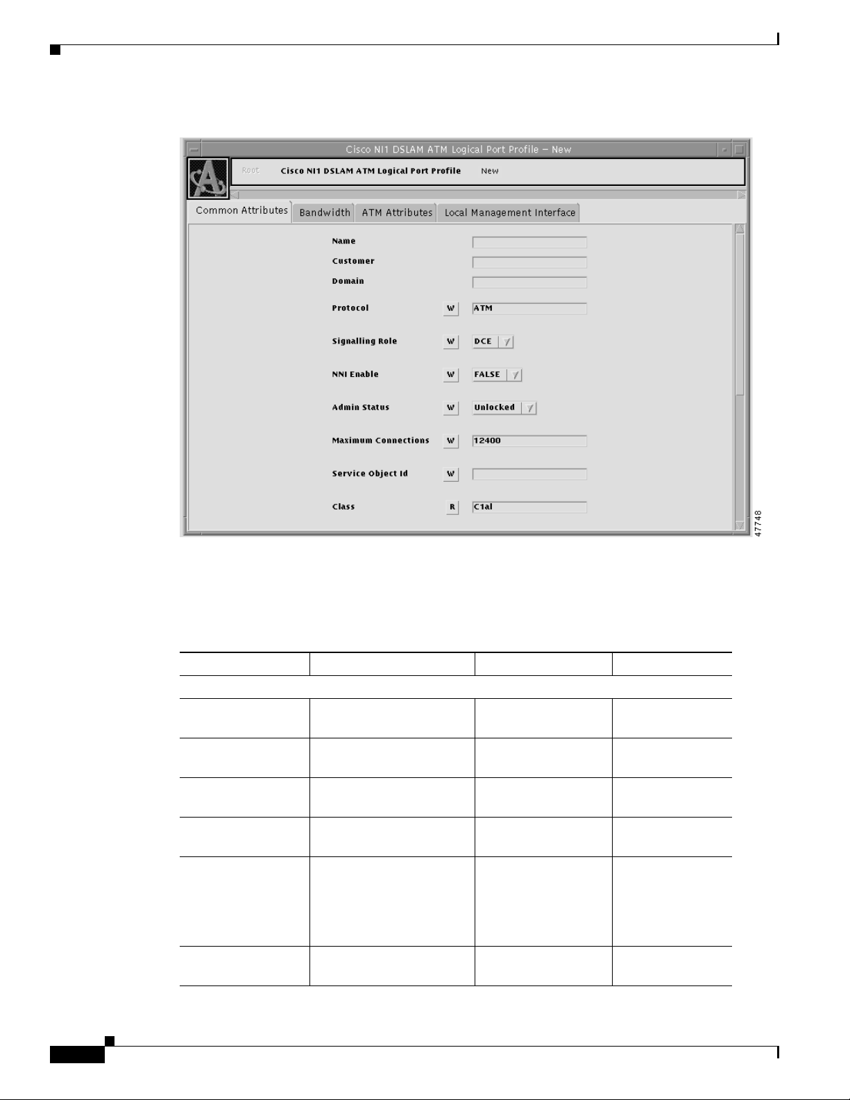
ATM Logical Port Profile Attributes
The ATM logical port profile provides you with access to the ATM attributes that you can configure for
an ATM logical port. If you do not create logical port profiles, the Equipment Module will communicate
the values specified in the default logical port profile.
Figure 6-2 shows a Cisco 6100/6130 ATM Logical Port Profile Object Viewer.
78-11339-01
Cisco Provisioning Center User’s Guide
6-21
Page 22
Working with Service Element Profiles
Figure 6-2 Cisco 6100/6130 ATM Logical Port Profile Object Viewer
Chapter 6 Configuring the Cisco NI-1 DLSAM Equipment Module
Table 6-5 lists the configurable attributes for a Cisco 6100/6130 ATM logical port profile. Attributes
marked with an asterisk "*" next to their Default Value indicates that these fields should not be changed.
Table 6-5 Cisco 6100/6130 ATM Logical Port Profile Attributes
Attribute Description Acceptable Values Default Values
Common Attributes
Name The logical port profile
name.
Text string (up to 24
characters)
Customer The customer name. Text string (up to 16
characters)
Domain The domain name. Text string (up to 16
characters)
Protocol The protocol used by this
logical port.
Signalling Role The DTE logical port type
Text string (up to 10
AT M*
characters)
DCE, DTE DCE
communicates with most
ATM CPEs. This logical
port type supports all types
of PVCs.
NNI Enable This feature is not
TRUE, FALSE FALSE*
supported in this release.
6-22
Cisco Provisioning Center User’s Guide
78-11339-01
Page 23

Chapter 6 Configuring the Cisco NI-1 DLSAM Equipment Module
Table 6-5 Cisco 6100/6130 ATM Logical Port Profile Attributes (continued)
Attribute Description Acceptable Values Default Values
Administrative
Status
Maximum
Connections
Specify the administrative
status of the logical port.
Specify the maximum
number of connections
supported for the logical
port.
Service Object ID The Service object ID that
owns this Service element.
Class The CPC class for this
logical port object.
Resource Map ATM-ATM PVC
connections are supported.
Peer Logical Port The peer logical port
(nodename/portname).
QoS The quality of service
provided by this logical
port.
Group The logical port group
membership. Allows
several logical ports to be
put in a common group as
a pooled resource. This
attribute is not applicable
to this Equipment Module.
Priority The logical port usage
priority.
Working with Service Element Profiles
Unlocked, Locked Unlocked
0-2147483647 4 for DSL physical
ports, 11304 for
WAN physical
ports, 3776 for
WAN subtending
ports.
Text string (up to 44
characters)
C1al C1al*
0-2147483647 48
Text string (up to 40
characters)
Text string (up to 32
characters)
Text string (up to 32
characters)
0-2147483647 0
*
UBR
*
78-11339-01
Cisco Provisioning Center User’s Guide
6-23
Page 24

Working with Service Element Profiles
Table 6-5 Cisco 6100/6130 ATM Logical Port Profile Attributes (continued)
Attribute Description Acceptable Values Default Values
Multiple Ranges Specify whether or not to
EMS Name The name of the logical
Bandwidth
Incoming Maximum
(kbits/s)
Outgoing Maximum
(kbits/s)
Incoming Nominal
Threshold (%)
Outgoing Nominal
Threshold (%)
Incoming
Committed (kbits/s)
Outgoing
Committed (kbits/s)
ATM Attributes
VPI ILMI ID The ILMI ID for the VPI. 0-2147483647 0
Max VCI bits The maximum VPI bits
VCI ILMI ID The ILMI ID for the VCI. 0-2147483647 0
Max VCI bits The maximum VCI
enable or disable multiple
ranges.
port used in the Element
Management System.
The maximum incoming
bandwidth for the logical
port.
The maximum outgoing
bandwidth for the logical
port.
Specify the incoming
committed bandwidth
nominal threshold
percentage.
Specify the outgoing
committed bandwidth
nominal threshold
percentage.
The incoming committed
bandwidth is
auto-calculated based on
the nominal threshold and
bandwidth.
The outgoing committed
bandwidth is
auto-calculated based on
the nominal threshold and
bandwidth.
(local).
(local).
Chapter 6 Configuring the Cisco NI-1 DLSAM Equipment Module
TRUE, FALSE FALSE
Text string (up to 65
*
characters)
0-2147483647 *
0-2147483647 *
0-2147483647 100
0-2147483647 100
0-2147483647 0*
0-2147483647 0*
0-255 8
0-1599 14
6-24
Cisco Provisioning Center User’s Guide
78-11339-01
Page 25

Chapter 6 Configuring the Cisco NI-1 DLSAM Equipment Module
Working with Service Element Profiles
Table 6-5 Cisco 6100/6130 ATM Logical Port Profile Attributes (continued)
Attribute Description Acceptable Values Default Values
Local Management Interface
Management
Protocol
Attributes
srchanmap This attribute is not
Specify the management
protocol that will be used
to manage the logical port.
supported in this release
None, ILMI None
Text string (up to 38
characters)
ATM-ATM Cross Connection Service Element Profile Attributes
The ATM-ATM Cross Connection Service element profile provides you with access to the additional
attributes that you can configure for a Cisco 6100/6130 ATM Cross Connect service through the Cisco
6100/6130 DSLAM. The ATM cross-connection object represents a cross connect between two ATM
logical ports in the same node. This Service object can be a VC between a DSL port and a Network
Interface (NI) port and also between subtending NI ports. The information you provide in the Service
element profile is communicated to the Cisco 6100/6130 DSLAM through the Equipment Module and
helps to define the type of service you are provisioning in the network. If you do not create Service
element profiles, the Equipment Module will communicate the values specified in the default Service
element profile.
Figure 6-3 shows the Cisco 6100/6130 ATM-ATM Cross-Connection Profile Object Viewer.
78-11339-01
Cisco Provisioning Center User’s Guide
6-25
Page 26

Working with Service Element Profiles
Figure 6-3 Cisco 6100/6130 ATM-ATM Cross Connection Profile Object Viewer
Chapter 6 Configuring the Cisco NI-1 DLSAM Equipment Module
6-26
Cisco Provisioning Center User’s Guide
78-11339-01
Page 27

Chapter 6 Configuring the Cisco NI-1 DLSAM Equipment Module
Table 6-6 lists the configurable attributes for a Cisco 6100/6130 ATM-ATM cross connections.
Attributes marked with an asterisk "*" next to their Default Value indicates that these fields should not
be changed.
Table 6-6 Cisco 6100/6130 ATM-ATM Cross Connection Profile Attributes
Attribute Name Description Acceptable Values Default Value
Common Attributes
Name The cross connection profile
name.
Customer The customer name. Text string (up to
Domain The domain name. Text string (up to
Recovery Priority This is not supported in this
release.
UNI Recovery Priority The recovery priority for UNI
resiliency.
Service Object ID The service object ID for the
cross connection.
A Endpoint VCI
1
The VCI for the subscriber or
transit subscriber side of the
6100/6130 switching fabric.
A Endpoint VPI
1
The VPI for the subscriber or
transit subscriber side of the
6100/6130 switching fabric.
Z Endpoint VCI
1
The VCI for the network side of
the 6100/6130 switching fabric.
Z Endpoint VPI
1
The VPI for the network side of
the 6100/6130 switching fabric.
ATM Attributes
Circuit Type The circuit type. VC, VP VC*
Class of Service You can specify the class of
service for traffic. The class of
service determines which traffic
descriptor you can select.
Working with Service Element Profiles
Text string (up to
24 characters)
16 characters)
16 characters)
0...n where 0
indicates that the
service should not
be moved, 1 is the
highest priority
and n is the lowest
priority
0...n where 0
indicates that the
service should not
be moved, 1 is the
highest priority
and n is the lowest
priority
Text string (up to
44 characters)
0-1599 0
-1-255 -1
0-1599 0
-1-255 -1
UBR UBR*
0
1
78-11339-01
Cisco Provisioning Center User’s Guide
6-27
Page 28

Working with Service Element Profiles
Table 6-6 Cisco 6100/6130 ATM-ATM Cross Connection Profile Attributes (continued)
Attribute Name Description Acceptable Values Default Value
A to Z, Z to A Directions
Bandwidth (kbits/s) The bandwidth for the cross
Primary Logical Port The original logical port that is
Substainable Cell Rate
(cells/s)
Peak Cell Rate (cells/s) PCR is the maximum allowed
Maximum Burst Size
(cells)
Cisco 6100/6130
Subscriber PVC Path Specify whether or not the
The Priority Queue The priority queue to which the
1. The following is a summary of VPI/VCI allocation within the Cisco 6100/6130:
DSL physical port: VPI (1), VCI (0-3); Subtending port: VPI (0-6), VCI (32-399) used for Virtual Channel
Connection (VCCs); VPI (7-255) used for Virtual Path Connections (VPCs); these are reserved for future use; WAN
physical port: VPI(0-27), VCI (32-399) used for VCCs, VPI (28-255) used for VPCs; these are reserved for future
use.
Chapter 6 Configuring the Cisco NI-1 DLSAM Equipment Module
connection.
being backed up by the he UNI
resiliency
(nodename/portname).
SCR is the maximum average
cell transmission rate that is
allowed over a given period of
time on a given circuit. It allows
the network to allocate
sufficient resources for
guaranteeing the network
performance objectives are met.
cell transmission rate. It defines
the shortest time period
between cells and provides the
highest guarantee that network
performance objectives (based
on cell loss ratio) will be met.
MBS is the maximum number
of cells that can be received at
the PCR. This allows a burst of
cells to arrive at a rate higher
than the SCR. If the burst is
larger than anticipated, the
additional cells are tagged or
dropped. This parameter applies
only to VBR traffic.
subscriber PVC is interleaved or
fast.
PVC is assigned. The highest
priority is QP1.
0-214783647 0
Text string (up to
44 characters)
0-910533065 0
0-910533065 0
0-214783647 0
Fast, Interleaved Interleaved
QP1, QP2, QP3 QP3
6-28
Cisco Provisioning Center User’s Guide
78-11339-01
 Loading...