

Page 1
© 2011 Cisco and/or its affiliates. All rights reserved. This document is Cisco Public Information. Page 1 of 41
Cisco Nexus B22HP
Design and Deployment Guide
September, 2011
For further information, questions and comments please contact ccbu-pricing@cisco.com
Design and Deployment Guide
Page 2

© 2011 Cisco and/or its affiliates. All rights reserved. This document is Cisco Public Information. Page 2 of 41
Contents
Introduction .............................................................................................................................................................. 3
Network Diagram ..................................................................................................................................................... 3
Hardware Installation............................................................................................................................................... 5
Fabric Extender Management Model ...................................................................................................................... 5
Fabric Connectivity Options ................................................................................................................................... 6
Static Pinning Fabric Interface Connection ........................................................................................................... 6
PortChannel Fabric Interface Connection ............................................................................................................. 7
Configuring a Fabric PortChannel ......................................................................................................................... 8
Virtual PortChannel Connection ........................................................................................................................... 10
Configuring a vPC ............................................................................................................................................... 10
Server Network Teaming ................................................................................................................................ ....... 13
Creating Host-Side vPC for Server Links with LACP .......................................................................................... 13
Configuring the HP Blade Server (Microsoft Windows 2008 Release 2) ............................................................. 14
Fibre Channel over Ethernet ................................................................................................................................. 17
Configuring FCoE ............................................................................................................................................... 17
Configuring the Cisco Nexus 5000 Series and B22HP for FCoE ........................................................................ 19
Debug Commands ................................................................................................................................................. 24
show fex .............................................................................................................................................................. 24
show fex detail .................................................................................................................................................... 25
show interface brief ............................................................................................................................................. 26
show interface ethernet 103/1/1 .......................................................................................................................... 28
show vlan ............................................................................................................................................................ 29
show interface fex-fabric ..................................................................................................................................... 30
Cisco Nexus Configurations ................................................................................................................................. 31
Cisco Nexus 5000 Series Switch 1 Configuration ............................................................................................... 31
Cisco Nexus 5000 Series Switch 2 Configuration ............................................................................................... 35
Conclusion ............................................................................................................................................................. 40
For More Information ............................................................................................................................................. 41
Page 3

© 2011 Cisco and/or its affiliates. All rights reserved. This document is Cisco Public Information. Page 3 of 41
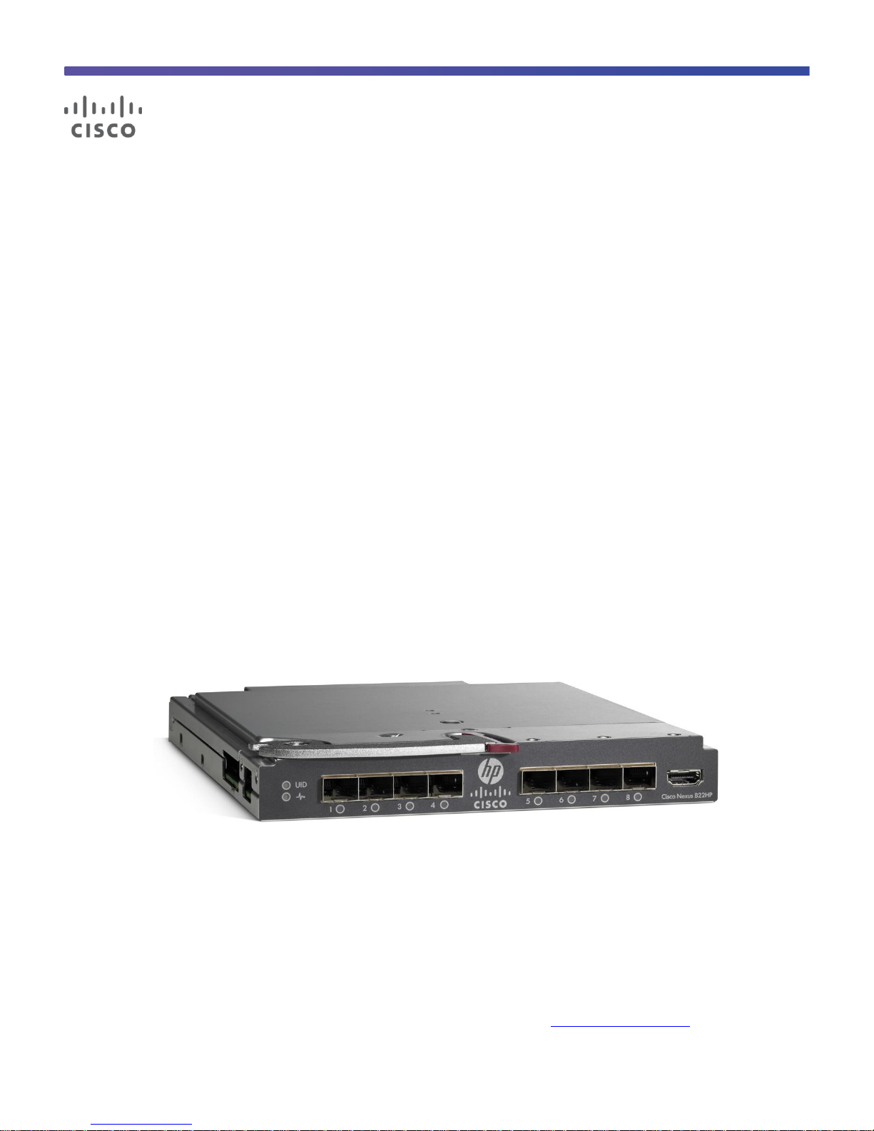
Introduction
The Cisco Nexus® B22 Blade Fabric Extender for HP (Cisco Nexus B22HP) provides an extension of the Cisco
Nexus switch fabric to the HP server edge. Logically, it behaves like a remote line card to a parent Cisco Nexus
5000 Series Switch. The fabric extender and the parent Cisco Nexus 5000 Series Switch together form a
distributed modular system. The Cisco Nexus B22HP forwards all traffic to the parent Cisco Nexus 5000 Series
Switch over eight 10 Gigabit Ethernet uplinks. Low-cost uplink connections of up to 10 meters can be made with
copper Twinax cable, and longer connections of up to 100 meters can use the Cisco Fabric Extender Transceiver
(FET-10G). Standard 10-Gbps optics such as short reach (SR) and long reach (LR) are also supported. Downlinks
to each server are auto negotiating for 1 and 10 Gigabit Ethernet and work with all HP Ethernet and converged
network adapter (CNA) mezzanines, allowing customers a choice of Ethernet, Fibre Channel over Ethernet
(FCoE), or Small Computer System Interface over IP (iSCSI) connections. Because the Cisco Nexus B22 is a
transparent extension of a Cisco Nexus 5000 Series Switch, traffic can be switched according to policies
established by the Cisco Nexus 5000 Series Switch with a single point of management.
The Cisco Nexus B22 provides the following benefits:
●
Highly scalable, consistent server access: This distributed modular system creates a scalable server access
environment with no reliance on Spanning Tree Protocol and with consistency between blade and rack
servers.
●
Simplified operations: The availability of one single point of management and policy enforcement using
upstream Cisco Nexus 5000 Series Switches eases the commissioning and decommissioning of blades
through zero-touch installation and automatic configuration of fabric extenders.
●
Increased business benefits: Consolidation, reduced cabling, investment protection through feature
inheritance from the parent switch, and the capability to add functions without the need for a major
equipment upgrade of server-attached infrastructure all contribute to reduced operating expenses (OpEx)
and capital expenditures (CapEx).
Each member of the Cisco Nexus B22 integrates into the I/O module slot of a third-party blade chassis, drawing
both power and cooling from the blade chassis itself.
Network Diagram
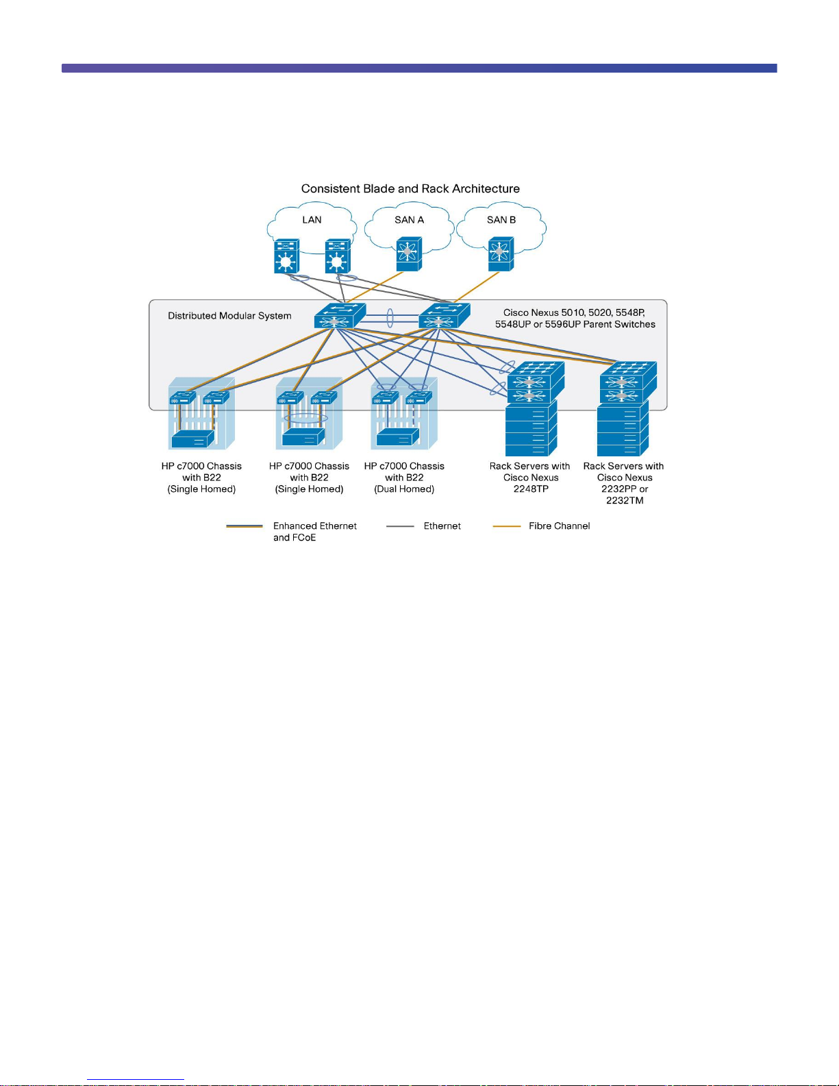
Figure 1 presents a sample network topology that can be built using the Cisco Nexus B22HP, Cisco Nexus 2000
Series Fabric Extenders, and Cisco Nexus 5000 Series Switches. In this topology, the Cisco Nexus 5000 Series
serves as the parent switch, performing all packet switching and policy enforcement for the entire distributed
modular system. The Cisco Nexus 5000 Series also serves as the only point of management for both configuration
and monitoring within the domain, making it simple to manage blade server and rack server connections together.
Page 4
© 2011 Cisco and/or its affiliates. All rights reserved. This document is Cisco Public Information. Page 4 of 41
Figure 1. Cisco Nexus Virtual Chassis Topology
The Cisco Nexus 5000 Series Switches, along with the Cisco Nexus 2000 Series and Cisco Nexus B22, create a
distributed modular system that unifies the data center architecture. Within this distributed modular system, both
blade servers and rack servers are managed identically. This approach allows the use of the same business and
technical processes and procedures for the network when addressing the computing environment.
The left most blade chassis in Figure 1 contains dual Cisco Nexus B22HP fabric extenders. Each Cisco Nexus
B22HP is singly attached to a parent Cisco Nexus 5500 switch platform, a connection mode referred to as straight
through mode. The fabric links can either be statically pinned or put into a PortChannel. This connection mode
helps ensure that all data packets from a particular Cisco Nexus B22 enter the same parent Cisco Nexus 5500
switch platform. This approach may be necessary when certain types of traffic must be restricted to either the left
or right Cisco Nexus 5500 switch platform: for instance, to maintain SAN A and SAN B separation. Also, in this
example the connections to individual blade servers are in active-standby mode, which helps ensure traffic flow
consistency but does not fully utilize the server network interface card (NIC) bandwidth.
The second blade chassis from the left in Figure 1 improves on the first with the creation of an Ethernet virtual
PortChannel (vPC) from the blade servers to the Cisco Nexus 5500. This vPC places the Ethernet portion of the
NICs in an active-active configuration, giving increased bandwidth to each host. The FCoE portion of the CNA is
also configured as active-active but maintains SAN A and SAN B separation because each virtual Fibre Channel
(VFC) interface is bound to a particular link at the server. This configuration also achieves high availability through
redundancy, and it can withstand a failure of a Cisco Nexus 5500 switch platform, a Cisco Nexus B22HP, or any
connecting cable. This topology is widely used in FCoE deployments.
Page 5

© 2011 Cisco and/or its affiliates. All rights reserved. This document is Cisco Public Information. Page 5 of 41
Card
IOM
LAN on motherboard (LOM)
IOM bays 1 and 2
Mezzanine card 1
IOM bays 3 and 4
Mezzanine card 2
IOM bay 5 and 6
The third blade chassis from the left in Figure 1 contains Cisco Nexus B22HP fabric extenders that connect to both
Cisco Nexus 5500 switch platforms through vPC for redundancy. In this configuration, active-active load balancing
using vPC from the blade server to the Cisco Nexus 5500 switch platform cannot be enabled. However, the servers
can still be dual-homed with active-standby or active-active transmit-load-balancing (TLB) teaming. This topology is
only for Ethernet traffic because SAN A and SAN B separation between the fabric extender and the parent switch
is necessary.
The last two setups illustrate how rack mount servers can connect to the same Cisco Nexus parent switch using
rack-mount Cisco Nexus 2000 Series Fabric Extenders. The topology for blade servers and rack-mount servers
can be identical if desired.
Hardware Installation
Installation of the Cisco Nexus B22HP in the rear of the HP BladeSystem c7000 chassis is similar to the installation
of other I/O modules (IOMs). The layout of the HP BladeSystem c7000 chassis, server types, and mezzanine cards
used determine the slots that should be populated with the Cisco Nexus B22HP for 1 and 10 Gigabit Ethernet
connectivity. Table 1 summarizes the typical options for half-height servers using dual-port 10 Gigabit Ethernet
devices.
Table 1. Mapping of HP BladeSystem c7000 Half-Height Server Mezzanine Card to IOM Bay
After the Cisco Nexus B22HP fabric extenders are installed, the onboard administrator (OA) should be updated to
at least Version 3.5 to help ensure that all functions and graphics are present. No configuration is required from the
chassis onboard administrator.
Fabric Extender Management Model
The Cisco Nexus fabric extenders are managed by a parent switch through the fabric interfaces using a zero-touch
configuration model. The switch discovers the fabric extender by a using detection protocol.
After discovery, if the fabric extender has been correctly associated with the parent switch, the following operations
are performed:
1. The switch checks the software image compatibility and upgrades the fabric extender if necessary.
2. The switch and fabric extender establish in-band IP connectivity with each other. The switch assigns an IP
address in the range of loopback addresses (127.15.1.0/24) to the fabric extender to avoid conflicts with IP
addresses that might be in use on the network.
3. The switch pushes the configuration data to the fabric extender. The fabric extender does not store any
configuration locally.
4. The fabric extender updates the switch with its operational status. All fabric extender information is displayed
using the switch commands for monitoring and troubleshooting.
This management model allows fabric extender modules to be added without adding management points or
complexity. Software image and configuration management is also automatically handled without user intervention.
Page 6

© 2011 Cisco and/or its affiliates. All rights reserved. This document is Cisco Public Information. Page 6 of 41
Interface
Fabric Link
1, 2, 3, 4, 5, 6, 7, and 8
Fabric link 1
9, 10, 11, 12, 13, 14, 15, and 16
Fabric link 2
Interface
Fabric Link
1, 2, 3, and 4
Fabric link 1
5, 6, 7, and 8
Fabric link 2
9, 10, 11, and 12
Fabric link 3
13,14,15, and 16
Fabric link 4
Fabric Connectivity Options
The Cisco Nexus B22HP creates a distributed modular chassis with the Cisco Nexus parent switch after a fabric
connection has been made over standard 10-Gbps cabling. This connection can be accomplished using any of the
following types of interconnects:
●
Cisco passive direct-attach cables (1M, 3M, or 5M)
●
Cisco active direct-attach cables (7M or 10M)
●
Cisco standard Enhanced Small Form-Factor Pluggable (SFP+) optics (SR or LR)
●
Cisco Fabric Extender Transceivers
After the fabric links have been physically established, the logical configuration of the links needs to be performed.
There are two methods of connection for the fabric links to the Cisco Nexus B22HP:
●
Static pinning fabric interface connection
●
PortChannel fabric interface connection
Static Pinning Fabric Interface Connection
Static Pinning is the default method of connection between the fabric extender and the Cisco Nexus parent switch.
In this mode of operation, a deterministic relationship exists between the host interfaces and the upstream parent
with up to eight fabric interfaces. These fabric interfaces are equally divided among the 16 server-side host ports. If
fewer fabric ports are allocated, then more server ports are assigned to a single fabric link. The advantage of this
configuration is that the traffic path and the amount of allocated bandwidth are always known for a particular set of
servers.
Since static pinning will group host-side ports into individual fabric links, you should understand its relationship and
how ports are grouped. The size of the port groups is determined by the number of host ports divided by the
max-link parameter value. Thus, if the max-link parameter is set to 2, then eight host ports would be assigned to
each link. The interfaces will be grouped in ascending order starting from the interface 1. Thus, interfaces 1 to 8 will
be pinned to one fabric link, and interfaces 9 to 16 will be pinned to a different interface (Table 2).
Table 2. Interface Assignment with Two Fabric Links
Table 3 summarizes the assignment with four fabric links with the max-link parameter set to 4, the interfaces are
divided into four groups.
Table 3. Interface Assignment with Two Fabric Links
Page 7

© 2011 Cisco and/or its affiliates. All rights reserved. This document is Cisco Public Information. Page 7 of 41
Interface
Fabric Link
1 and 2
Fabric link 1
3 and 4
Fabric link 2
5 and 6
Fabric link 3
7 and 8
Fabric link 4
9 and 10
Fabric link 5
11 and 12
Fabric link 6
13 and 14
Fabric link 7
15 and 16
Fabric link 8
Table 4 summarizes the assignment of eight fabric links with the max-link parameter set to 8; the interfaces are
divided into eight groups.
Table 4. Interface Assignment with Two Fabric Links
Note: The assignment of the host-side ports is always based on the configured max-link parameter and not the
actual physical number of fabric ports connected. Be sure to match the max-link parameter with the actual number
of physical links used.
Note: The relationship of host-side ports to parent switch fabric ports is static. If a fabric interface fails, all its
associated host interfaces are brought down and will remain down until the fabric interface is restored.
PortChannel Fabric Interface Connection
The PortChannel fabric interface provides an alternative method of connection between the parent switch and the
Cisco Nexus B22HP fabric extender. In this mode of operation, the physical fabric links are bundled into a single
logical channel. This approach prevents a single fabric interconnect link loss from disrupting traffic to any one
server. The total bandwidth of the logical channel is shared by all the servers, and traffic is spread across the
members through the use of a hash algorithm.
●
For a Layer 2 frame, the switch uses the source and destination MAC addresses.
●
For a Layer 3 frame, the switch uses the source and destination MAC addresses and the source and
destination IP addresses.
Since both redundancy and increased bandwidth are possible, configuration of the fabric links on a PortChannel is
the most popular connection option.
Page 8

© 2011 Cisco and/or its affiliates. All rights reserved. This document is Cisco Public Information. Page 8 of 41
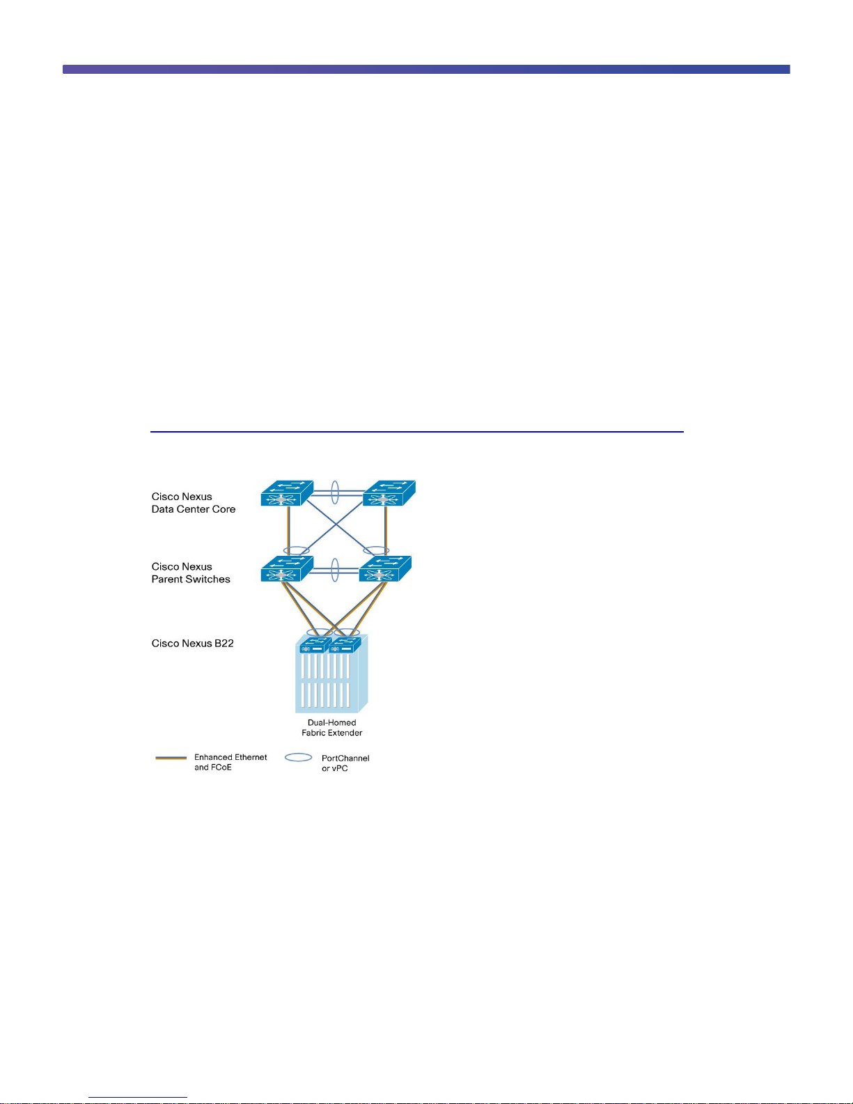
Figure 2 shows PortChannel designs.
Note: A fabric interface that fails in the PortChannel does not trigger a change to the host interfaces. Traffic is
automatically redistributed across the remaining links in the PortChannel fabric interface.
Figure 2. PortChannel Designs
Configuring a Fabric PortChannel
1. Log into the first parent switch and enter into configuration mode.
Nexus 5000 Switch
login: admin
Password:
Cisco Nexus Operating System (NX-OS) Software
TAC support: http://www.cisco.com/tac
Copyright (c) 2002-2011, Cisco Systems, Inc. All rights reserved.
The copyrights to certain works contained in this software are
owned by other third parties and used and distributed under
license. Certain components of this software are licensed under
the GNU General Public License (GPL) version 2.0 or the GNU
Lesser General Public License (LGPL) Version 2.1. A copy of each
such license is available at
http://www.opensource.org/licenses/gpl-2.0.php and
http://www.opensource.org/licenses/lgpl-2.1.php
N5548-Bottom# configure terminal
Enter configuration commands, one per line. End with CNTL/Z.
N5548-Bottom(config)#
2. Enable the fabric extender feature.
N5548-Bottom(config)#
N5548-Bottom(config)# feature fex
Page 9

© 2011 Cisco and/or its affiliates. All rights reserved. This document is Cisco Public Information. Page 9 of 41
N5548-Bottom(config)#
3. Logically create the fabric extender.
N5548-Bottom(config)#
N5548-Bottom(config)# fex 103
N5548-Bottom(config-fex)#
4. Create the PortChannel, change the port mode, and associate the fabric extender with the PortChannel.
N5548-Bottom(config-if)# interface port-channel 3
N5548-Bottom(config-if)# switchport mode fex-fabric
N5548-Bottom(config-if)# fex associate 103
N5548-Bottom(config-if)#
5. Assign the Cisco Nexus parent switch ports to the PortChannel.
N5548-Bottom(config-if)# interface ethernet 1/1
N5548-Bottom(config-if)# switchport mode fex-fabric
N5548-Bottom(config-if)# fex associate 103
N5548-Bottom(config-if)# channel-group 3
N5548-Bottom(config-if)# interface ethernet 1/2
N5548-Bottom(config-if)# switchport mode fex-fabric
N5548-Bottom(config-if)# fex associate 103
N5548-Bottom(config-if)# channel-group 3
6. Repeat the steps on the second Cisco Nexus 5000 Series Switch connected to the fabric extender in
interconnect bay 4.
N5548-Top# configure terminal
N5548-Top(config)# feature fex
N5548-Top(config)# fex 104
N5548-Top(config-if)# interface port-channel 4
N5548-Top(config-if)# switchport mode fex-fabric
N5548-Top(config-if)# fex associate 104
N5548-Top(config-if)# interface ethernet 1/1
N5548-Top(config-if)# switchport mode fex-fabric
N5548-Top(config-if)# fex associate 104
N5548-Top(config-if)# channel-group 4
N5548-Top(config-if)# interface ethernet 1/2
N5548-Top(config-if)# switchport mode fex-fabric
N5548-Top(config-if)# fex associate 104
N5548-Top(config-if)# channel-group 4
Page 10
© 2011 Cisco and/or its affiliates. All rights reserved. This document is Cisco Public Information. Page 10 of 41
7. Verify that the Cisco Nexus B22HP is up and running.
switch(config-if)# show fex
FEX FEX FEX FEX
Number Description State Model Serial
------------------------------------------------------------------------
103 FEX0103 Online N2K-B22HP-P FOC1515ZZU4
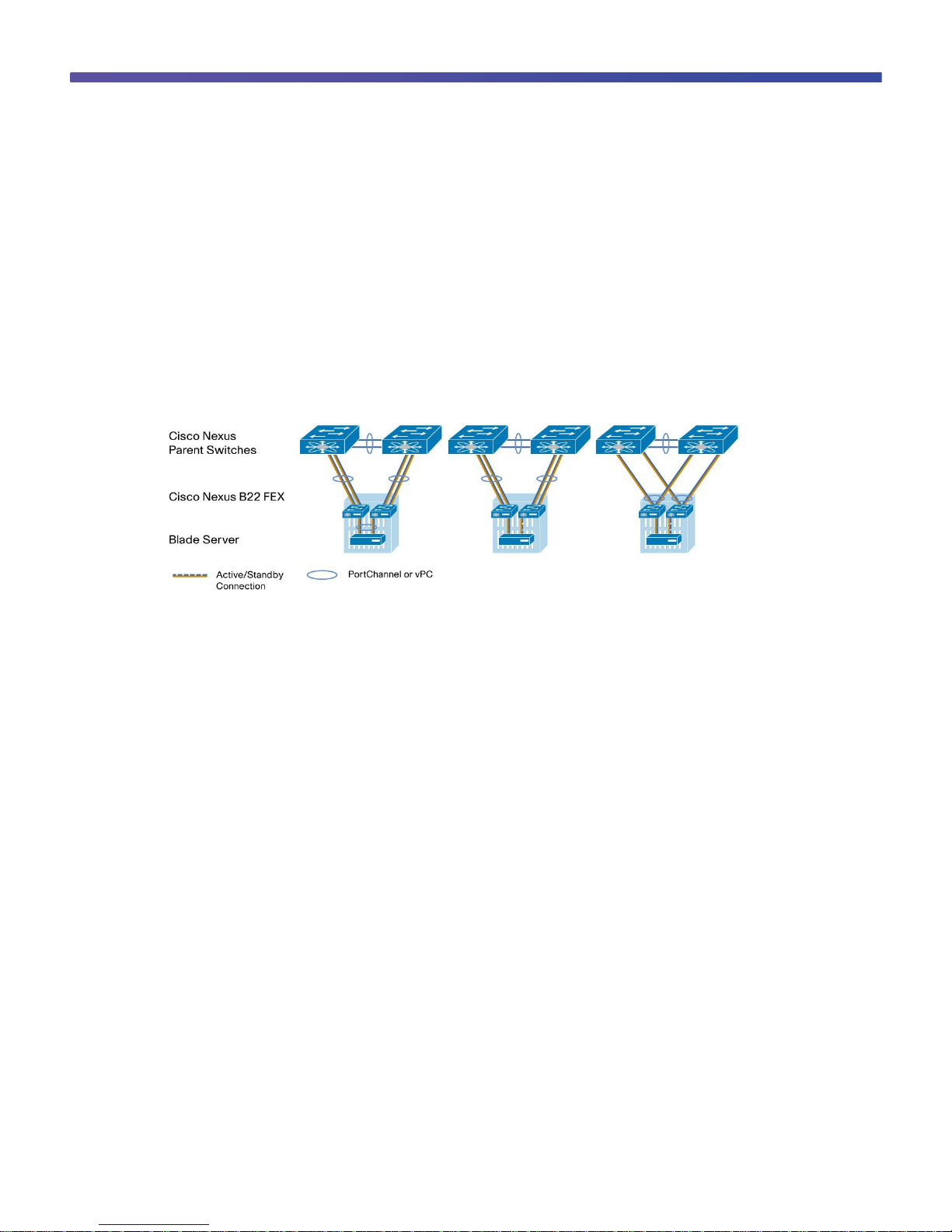
Virtual PortChannel Connection
vPCs allow links that are physically connected to two different Cisco Nexus switches to form a PortChannel to a
downstream device. The downstream device can be a switch, a server, or any other networking device that
supports IEEE 802.3ad PortChannels. vPC technology enables networks to be designed with multiple links for
redundancy while also allowing those links to connect to different endpoints for added resiliency (Figure 3).
More information about vPC technology can be found at
http://www.cisco.com/en/US/products/ps9670/products_implementation_design_guides_list.html.
Figure 3. Blade Server Configuration Options
Configuring a vPC
Enable vPC (this configuration should be implemented on both switches in parallel):
1. Enable the vPC feature
2. Create the vPC domain
3. Configure the peer keepalive link
4. Configure the vPC peer link PortChannel
5. Check the status of vPC
1. Enable the vPC feature.
N5548-Bottom# configure terminal
N5548-Bottom(config)# feature vpc
Page 11

© 2011 Cisco and/or its affiliates. All rights reserved. This document is Cisco Public Information. Page 11 of 41
N5548-Top# configure terminal
N5548-Top(config)# feature vpc
2. Create the vPC domain (should be unique within network).
N5548-Bottom(config)# vpc domain 5
N5548-Top(config)# vpc domain 5
3. Configure the peer keepalive link over the management network.
N5548-Bottom(config-vpc-domain)# peer-keepalive destination 172.25.182.104 source
172.25.182.103
Note:
--------:: Management VRF will be used as the default VRF ::--------
N5548-Top(config-vpc-domain)# peer-keepalive destination 172.25.182.103 source
172.25.182.104
Note:
--------:: Management VRF will be used as the default VRF ::--------
4. Configure the vPC peer link.
N5548-Bottom# interface port-channel 20
N5548-Bottom(config-if)# interface ethernet 1/9
N5548-Bottom(config-if)# channel-group 20
N5548-Bottom(config-if)# interface ethernet 1/10
N5548-Bottom(config-if)# channel-group 20
N5548-Bottom(config-if)# interface port-channel 20
N5548-Bottom(config-if)# vpc peer-link
Please note that spanning tree port type is changed to “network” port type on vPC
peer-link.
This will enable spanning tree Bridge Assurance on vPC peer-link provided the STP
Bridge Assurance
(which is enabled by default) is not disabled.
N5548-Bottom(config-if)#
N5548-Top# interface port-channel 20
Page 12

© 2011 Cisco and/or its affiliates. All rights reserved. This document is Cisco Public Information. Page 12 of 41
N5548-Top (config-if)# interface ethernet 1/9
N5548-Top(config-if)# channel-group 20
N5548-Top(config-if)# interface ethernet 1/10
N5548-Top(config-if)# channel-group 20
N5548-Top(config-if)# interface port-channel 20
N5548-Top(config-if)# vpc peer-link
Please note that spanning tree port type is changed to “network” port type on vPC
peer-link.
This will enable spanning tree Bridge Assurance on vPC peer-link provided the STP
Bridge Assurance
(which is enabled by default) is not disabled.
N5548-Bottom(config-if)#
5. Check the vPC status.
N5548-Bottom(config-if)# show vpc
Legend:
(*) - local vPC is down, forwarding via vPC peer-link
vPC domain id : 5
Peer status : peer adjacency formed ok
vPC keep-alive status : peer is alive
Configuration consistency status: success
Per-vlan consistency status : success
Type-2 consistency status : success
vPC role : primary
Number of vPCs configured : 0
Peer Gateway : Disabled
Dual-active excluded VLANs : -
Graceful Consistency Check : Enabled
vPC Peer-link status
---------------------------------------------------------------------
id Port Status Active vlans
-- ---- ------ --------------------------------------------------
1 Po20 up 1
N5548-Bottom(config-if)#
Now the two switches have been configured to support vPC links to other devices. These connections can be used
for upstream links to the data center core. These vPC links can be used for connections to hosts in the data center,
allowing additional bandwidth and redundant links.
Page 13
© 2011 Cisco and/or its affiliates. All rights reserved. This document is Cisco Public Information. Page 13 of 41
Server Network Teaming
Server NIC teaming provides an additional layer of redundancy to servers. It allows multiple links to be available,
for redundancy. In the blade server environment, server network teaming was typically limited to active-standby
configurations and could not provide active-active links, because active-active links required EtherChannel or Link
Aggregation Control Protocol (LACP) connection to a single switch. Since the Cisco Nexus B22HP fabric extender
is an extension of the parent switch, EtherChannel or LACP connections can be created between the blade server
and the virtual chassis. Dual Cisco Nexus 5000 Series switches can be used with vPC for additional switch
redundancy while providing active-active links to servers, thus enabling aggregate 40-Gbps bandwidth with dual
links (Figure 4).
Figure 4. Fabric Link and Server Topologies
Creating Host-Side vPC for Server Links with LACP
1. Enable LACP on both parent switches.
5548-Bottom (config)# feature lacp
2. Create the blade server vPC and add the member interface.
nexus-5548-Bottom# configure terminal
Enter configuration commands, one per line. End with CNTL/Z.
5548-Bottom(config)# interface port-channel 201
5548-Bottom(config-if)# vpc 201
5548-Bottom(config-if)# switchport mode access
5548-Bottom(config-if)# no shutdown
5548-Bottom(config-if)# interface ethernet 103/1/1
5548-Bottom(config-if)# channel-group 201 mode active
nexus-5558-Top# configure terminal
Enter configuration commands, one per line. End with CNTL/Z.
5548-Top(config)# interface port-channel 201
5548-Top(config-if)# vpc 201
5548-Top(config-if)# switchport mode access
5548-Top(config-if)# no shutdown
5548-Top(config-if)# interface ethernet 104/1/1
5548-Top(config-if)# channel-group 201 mode active
Page 14

© 2011 Cisco and/or its affiliates. All rights reserved. This document is Cisco Public Information. Page 14 of 41
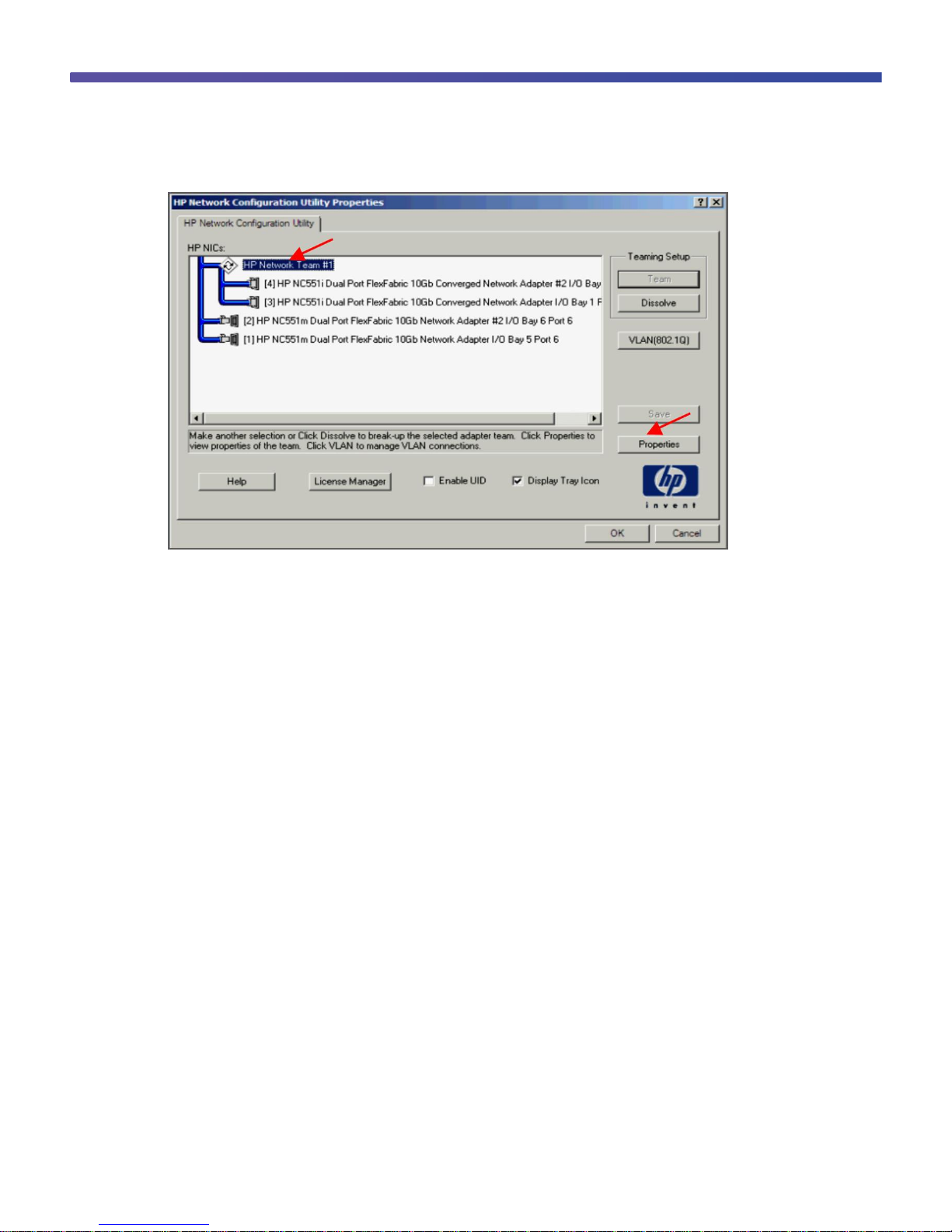
Configuring the HP Blade Server (Microsoft Windows 2008 Release 2)
1. Open the Control Panel and open HP Network Config Utility.
2. Select the network ports and click Team.
Page 15

© 2011 Cisco and/or its affiliates. All rights reserved. This document is Cisco Public Information. Page 15 of 41
3. After the team is formed, click Properties.
4. From the Team Type Selection drop-down menu, choose 802.3ad Dynamic with Fault Tolerance to match the
Cisco Nexus vPC configuration with LACP. Then click OK.
Page 16
© 2011 Cisco and/or its affiliates. All rights reserved. This document is Cisco Public Information. Page 16 of 41
5. Click OK to complete the NIC teaming configuration. It may take a few minutes to complete after you click OK.
To verify that the vPC is formed, go to one of the Cisco Nexus 5000 Series Switches to check the status of the
server PortChannel interface. Since the pair of Cisco Nexus 5000 Series Switches is in a vPC configuration, they
each have a single port in the PortChannel. Checking the status of the PortChannel on each parent switch shows
that channel group 201 is in the “P - Up in port-channel” state on each switch. A check from the HP Network
Configuration Utility will show the status “Available” for each link that is up in the PortChannel.
5548-Bottom# show port-channel summary
Flags: D - Down P - Up in port-channel (members)
I - Individual H - Hot-standby (LACP only)
s - Suspended r - Module-removed
S - Switched R - Routed
U - Up (port-channel)
-------------------------------------------------------------------------------
Group Port- Type Protocol Member Ports
Channel
-------------------------------------------------------------------------------
20 Po20(SU) Eth NONE Eth1/9(P) Eth1/10(P)
103 Po103(SU) Eth NONE Eth1/1(P) Eth1/2(P)
201 Po201(SU) Eth LACP Eth103/1/1(P)
5548-Bottom #
N5548-Top# show port-channel summary
Flags: D - Down P - Up in port-channel (members)
I - Individual H - Hot-standby (LACP only)
s - Suspended r - Module-removed
S - Switched R - Routed
U - Up (port-channel)
Page 17

© 2011 Cisco and/or its affiliates. All rights reserved. This document is Cisco Public Information. Page 17 of 41
-------------------------------------------------------------------------------
Group Port- Type Protocol Member Ports
Channel
-------------------------------------------------------------------------------
4 Po4(SU) Eth NONE Eth1/2(P)
20 Po20(SU) Eth NONE Eth1/9(P) Eth1/10(D)
201 Po201(SU) Eth LACP Eth104/1/1(P)
N5548-Top#
Fibre Channel over Ethernet
FCoE combines LAN and storage traffic on a single link, eliminating dedicated adapters, cables, and devices for
each type of network, resulting in savings that can extend the life of the data center. The Cisco Nexus B22HP is
the building block that enables FCoE traffic to travel outside the HP BladeSystem chassis.
Best practice considerations for unified fabric are listed in the Cisco Nexus 5000 Series NX-OS Operations Guide
at http://www.cisco.com/en/US/docs/switches/datacenter/nexus5000/sw/operations/n5k_ops_guide.html.
Configuring FCoE
Follow these steps to configure FCoE:
1. Enable the FCoE personality on the HP NC551 or NC553 CNA.
2. Install the FCoE driver in the server OS.
3. Configure quality of service (QoS) to support FCoE on the Cisco Nexus 5000 Series.
4. Enable the FCoE feature on the Cisco Nexus 5000 Series.
5. Create the SAN A and SAN B VLANs.
6. Create VFC interfaces.
Page 18

© 2011 Cisco and/or its affiliates. All rights reserved. This document is Cisco Public Information. Page 18 of 41
The steps are described in detail on the following pages.
1. Enable FCoE on the CNA.
By default, the HP NC551 and NC553 CNAs have their personality set to iSCSI. The personality needs to be
changed to FCoE to support FCoE traffic. You make this change in the BIOS of the system and the BIOS of the
mezzanine cards.
Choose System Options.
Choose NIC Personality Options.
From the NIC Personality Options menu, choose FCoE.
Page 19

© 2011 Cisco and/or its affiliates. All rights reserved. This document is Cisco Public Information. Page 19 of 41
Save the changes by exiting the BIOS; then reboot the server to enable the changes. FCoE capabilities are
enabled at this time. Verify that the latest FCoE drivers and firmware are loaded for the respective operating
system. The latest versions can be obtained from the HP Support website. The FCoE drivers are separate from the
Ethernet NIC drivers. Figure 5 shows the ports configured for FCoE and the drivers loaded.
Figure 5. OneCommand FCoE Utility Showing Ports Configured for FCoE with Drivers Loaded
Configuring the Cisco Nexus 5000 Series and B22HP for FCoE
This example assumes that a server in bay 2 is using IOM 3 and 4 for FCoE connectivity.
1. Enable the FCoE feature on the Cisco Nexus 5000 Series Switch.
N5548-Bottom # config terminal
Enter configuration commands, one per line. End with CNTL/Z.
switch(config)# feature fcoe
FC license checked out successfully
fc_plugin extracted successfully
FC plugin loaded successfully
FCoE manager enabled successfully
FC enabled on all modules successfully
Warning: Ensure class-fcoe is included in qos policy-maps of all types
N5548-Bottom (config)#
N5548-Top # config terminal
Enter configuration commands, one per line. End with CNTL/Z.
switch(config)# feature fcoe
FC license checked out successfully
fc_plugin extracted successfully
Page 20

© 2011 Cisco and/or its affiliates. All rights reserved. This document is Cisco Public Information. Page 20 of 41
FC plugin loaded successfully
FCoE manager enabled successfully
FC enabled on all modules successfully
Warning: Ensure class-fcoe is included in qos policy-maps of all types
N5548-Top (config)#
2. Configure QoS to support FCoE.
N5548-Bottom(config)# system qos
N5548-Bottom(config-sys-qos)# service-policy type qos input fcoe-default-inpolicy
N5548-Bottom(config-sys-qos)# service-policy type queuing input fcoe-default-inpolicy
N5548-Bottom(config-sys-qos)# service-policy type queuing output fcoe-defaultout-policy
N5548-Bottom(config-sys-qos)# service-policy type network-qos fcoe-default-nqpolicy
N5548-Bottom(config-sys-qos)#
N5548-Top(config)# system qos
N5548-Top(config-sys-qos)# service-policy type qos input fcoe-default-in-policy
N5548-Top(config-sys-qos)# service-policy type queuing input fcoe-default-inpolicy
N5548-Top(config-sys-qos)# service-policy type queuing output fcoe-default-outpolicy
N5548-Top(config-sys-qos)# service-policy type network-qos fcoe-default-nq-policy
N5548-Top(config-sys-qos)#
3. Create the virtual Fibre Channel interface (physical port).
N5548-Bottom(config)#
N5548-Bottom(config)# interface vfc 1032
N5548-Bottom(config-if)# switchport mode F
N5548-Bottom(config-if)# bind interface ethernet 103/1/2
N5548-Bottom(config-if)# no shut
N5548-Bottom(config-if)#
N5548-Top(config)#
N5548-Top(config)# interface vfc 1032
N5548-Top(config-if)# switchport mode F
N5548-Top(config-if)# bind interface ethernet 104/1/2
N5548-Top(config-if)# no shut
N5548-Top(config-if)#
Page 21

© 2011 Cisco and/or its affiliates. All rights reserved. This document is Cisco Public Information. Page 21 of 41
or
Create the virtual Fibre Channel interface (PortChannel).
N5548-Bottom(config)#
N5548-Bottom(config)# interface vfc 1032
N5548-Bottom(config-if)# switchport mode F
N5548-Bottom(config-if)# bind interface port-channel 201
N5548-Bottom(config-if)# no shut
N5548-Bottom(config-if)#
N5548-Top(config)#
N5548-Top(config)# interface vfc 1032
N5548-Top(config-if)# switchport mode F
N5548-Top(config-if)# bind interface port-channel 201
N5548-Top(config-if)# no shut
N5548-Top(config-if)#
4. Create the FCoE VSAN and map it to the VLAN.
N5548-Bottom(config)# vlan 200
N5548-Bottom(config-vlan)# fcoe vsan 200
N5548-Bottom(config-vlan)#
N5548-Top(config)# vlan 201
N5548-Top(config-vlan)# fcoe vsan 201
N5548-Top(config-vlan)#
5. Configure the VLANs allowed to transverse the vPC links.
N5548-Bottom(config)# interface port-channel 20
N5548-Bottom(config-if)# switchport trunk allowed vlan 1, 200
N5548-Bottom(config-vsan-db)#
N5548-Top(config)# interface port-channel 20
N5548-Top(config-vsan-db)# switchport trunk allowed vlan 1, 201
N5548-Top(config-vsan-db)#
6. Bind the entry in the VSAN database.
N5548-Bottom(config)#
N5548-Bottom(config)# vsan database
N5548-Bottom(config-vsan-db)# vsan 200
N5548-Bottom(config-vsan-db)# vsan 200 interface vfc1032
N5548-Bottom(config-vsan-db)#
Page 22

© 2011 Cisco and/or its affiliates. All rights reserved. This document is Cisco Public Information. Page 22 of 41
N5548-Top(config)#
N5548-Top(config)# vsan database
N5548-Top(config-vsan-db)# vsan 201
N5548-Top(config-vsan-db)# vsan 201 interface vfc1032
N5548-Top(config-vsan-db)#
Note: The VLAN and VSAN numbers do not have to be the same.
7. Configure the Fibre Channel interface port type.
N5548-Bottom(config)# interface fc 1/32
N5548-Bottom(config-if)# switchport mode F
N5548-Bottom(config-if)#
N5548-Top(config)# interface fc 1/32
N5548-Top(config-if)# switchport mode F
N5548-Top(config-if)#
8. Bind the VSAN to the Fibre Channel interface.
N5548-Bottom(config)# vsan database
N5548-Bottom(config-vsan-db)# vsan 200 interface fc 1/32
N5548-Bottom(config-vsan-db)#
N5548-Top(config)# vsan database
N5548-Top(config-vsan-db)# vsan 201 interface fc 1/32
N5548-Top(config-vsan-db)#
9. Create the necessary zone and zone sets with appropriate members.
N5548-Bottom(config)# zone name zone1 vsan 200
N5548-Bottom(config-zone)# member pwwn 50:00:40:20:02:f4:65:2b
N5548-Bottom(config-zone)# member pwwn 10:00:78:e3:b5:f6:b3:59
N5548-Bottom(config-zone)# zoneset name zoneset1 vsan 200
N5548-Bottom(config-zoneset)# member zone1
N5548-Top(config)# zone name zone2 vsan 201
N5548-Top(config-zone)# member pwwn 50:00:40:21:02:f4:65:2b
N5548-Top(config-zone)# member pwwn 10:00:78:e3:b5:f6:b3:5d
N5548-Top(config-zone)# zoneset name zoneset2 vsan 201
N5548-Top(config-zoneset)# member zone2
Page 23

© 2011 Cisco and/or its affiliates. All rights reserved. This document is Cisco Public Information. Page 23 of 41
Note: Use a relevant display command (for example, show interface or show flogi database) to obtain the
required value in hexadecimal format.
10. Activate the Zone Sets.
N5548-Bottom(config-zoneset)# zoneset activate name zoneset1 vsan 200
N5548-Top(config-zoneset)# zoneset activate name zoneset2 vsan 201
The following commands can now be used to check connectivity between the blade
server and the Cisco Nexus B22HP.
N5548-Bottom# show flogi database
-------------------------------------------------------------------------------
INTERFACE VSAN FCID PORT NAME NODE NAME
-------------------------------------------------------------------------------
vfc1032 200 0x550000 10:00:b4:99:ba:fb:41:41 20:00:b4:99:ba:fb:41:41
Total number of flogi = 1.
N5548-Bottom#
N5548-Bottom# show fcns database
VSAN 200:
--------------------------------------------------------------------------
FCID TYPE PWWN (VENDOR) FC4-TYPE:FEATURE
--------------------------------------------------------------------------
0x550000 N 10:00:b4:99:ba:fb:41:41 ipfc scsi-fcp:init
Total number of entries = 1
N5548-Bottom#
Page 24

© 2011 Cisco and/or its affiliates. All rights reserved. This document is Cisco Public Information. Page 24 of 41
Figure 6 shows a server that has successfully connected to the SAN.
Figure 6. Server with FCoE Connected to Volumes on a Fibre Channel Array
Debug Commands
show fex
Displays the status of the fabric extenders that are powered on and connected
Cisco Nexus B22HP installed but parent switch not configured
N5548-Bottom# show fex
FEX FEX FEX FEX
Number Description State Model Serial
------------------------------------------------------------------------
--- -------- Discovered N2K-B22HP-P FOC1515ZZU4
N5548-Bottom#
Page 25

© 2011 Cisco and/or its affiliates. All rights reserved. This document is Cisco Public Information. Page 25 of 41
Cisco Nexus B22HP loading after the parent switch is configured
N5548-Bottom(config-if)# show fex
FEX FEX FEX FEX
Number Description State Model Serial
------------------------------------------------------------------------
103 FEX0103 Connected N2K-B22HP-P FOC1515ZZU4
N5548-Bottom(config-if)#
Cisco Nexus B22HP online and ready for use
N5548-Top# show fex
FEX FEX FEX FEX
Number Description State Model Serial
------------------------------------------------------------------------
104 FEX0104 Online N2K-B22HP-P FOC1515ZZUU
N5548-Top#
N5548-Top#
show fex detail
Displays the details of the fabric extender module, including the IOM bay number, rack name, and enclosure
information of the HP BladeSystem c-Class chassis
N5548-Top# show fex detail
FEX: 104 Description: FEX0104 state: Online
FEX version: 5.0(3)N2(2) [Switch version: 5.0(3)N2(2)]
FEX Interim version: 5.0(3)N2(2)
Switch Interim version: 5.0(3)N2(2)
Extender Model: N2K-B22HP-P, Extender Serial: FOC151425GA
Part No: 73-13780-05
Bay: 4
Rack: UnnamedRack
Enclosure: 1Z34AB789012
Enclosure Serial: USE6401VEX
Rack Id: Default RUID
Card Id: 145, Mac Addr: e8:b7:48:4b:cd:42, Num Macs: 262208
Module Sw Gen: 12594 [Switch Sw Gen: 21]
post level: complete
pinning-mode: static Max-links: 1
Fabric port for control traffic: Eth1/1
Fabric interface state:
Po4 - Interface Up. State: Active
Eth1/1 - Interface Up. State: Active
Page 26

© 2011 Cisco and/or its affiliates. All rights reserved. This document is Cisco Public Information. Page 26 of 41
Eth1/2 - Interface Up. State: Active
Fex Port State Fabric Port
Eth104/1/1 Down Po4
Eth104/1/2 Down Po4
Eth104/1/3 Down Po4
Eth104/1/4 Down Po4
Eth104/1/5 Down Po4
Eth104/1/6 Down Po4
Eth104/1/7 Down Po4
Eth104/1/8 Down Po4
Eth104/1/9 Down Po4
Eth104/1/10 Down Po4
Eth104/1/11 Down Po4
Eth104/1/12 Down Po4
Eth104/1/13 Down Po4
Eth104/1/14 Down Po4
Eth104/1/15 Down Po4
Eth104/1/16 Down Po4
Logs:
06/08/2011 15:33:26.491828: Module register received
06/08/2011 15:33:26.493406: Registration response sent
06/08/2011 15:33:26.736842: Module Online Sequence
06/08/2011 15:33:29.625679: Module Online
N5548-Top#
show interface brief
N5548-Top# show interface brief
--------------------------------------------------------------------------------
Ethernet VLAN Type Mode Status Reason Speed Port
Interface Ch #
--------------------------------------------------------------------------------
Eth1/1 1 eth fabric up none 10G(D) --
Eth1/2 1 eth fabric up none 10G(D) 4
Eth1/3 1 eth fabric up none 10G(D) --
Eth1/4 1 eth fabric up none 10G(D) --
Eth1/5 1 eth fabric up none 10G(D) --
Eth1/6 1 eth access down SFP not inserted 10G(D) --
Eth1/7 1 eth access down SFP not inserted 10G(D) --
Eth1/8 1 eth access down SFP not inserted 10G(D) --
Eth1/9 1 eth access down SFP not inserted 10G(D) --
Eth1/10 1 eth access down SFP not inserted 10G(D) --
Eth1/11 1 eth access down SFP not inserted 10G(D) --
Page 27

© 2011 Cisco and/or its affiliates. All rights reserved. This document is Cisco Public Information. Page 27 of 41
Eth1/12 1 eth access down SFP not inserted 10G(D) --
Eth1/13 1 eth access down SFP not inserted 10G(D) --
Eth1/14 1 eth access down SFP not inserted 10G(D) --
Eth1/15 1 eth access down SFP not inserted 10G(D) --
Eth1/16 1 eth access down SFP not inserted 10G(D) --
Eth1/17 1 eth access down SFP not inserted 10G(D) --
Eth1/18 1 eth access down SFP not inserted 10G(D) --
Eth1/19 1 eth access down SFP not inserted 10G(D) --
Eth1/20 1 eth access down SFP not inserted 10G(D) --
Eth1/21 1 eth access down SFP not inserted 10G(D) --
Eth1/22 1 eth access down SFP not inserted 10G(D) --
Eth1/23 1 eth access down SFP not inserted 10G(D) --
Eth1/24 1 eth access down SFP not inserted 10G(D) --
Eth1/25 1 eth access down SFP not inserted 10G(D) --
Eth1/26 1 eth access down SFP not inserted 10G(D) --
Eth1/27 1 eth access down SFP not inserted 10G(D) --
Eth1/28 1 eth access down SFP not inserted 10G(D) --
Eth1/29 1 eth access down SFP not inserted 10G(D) --
Eth1/30 1 eth access down SFP not inserted 10G(D) --
Eth1/31 1 eth access down SFP not inserted 10G(D) --
Eth1/32 1 eth access down SFP not inserted 10G(D) --
--------------------------------------------------------------------------------
Port-channel VLAN Type Mode Status Reason Speed Protocol
Interface
--------------------------------------------------------------------------------
Po4 1 eth fabric up none a-10G(D) none
--------------------------------------------------------------------------------
Port VRF Status IP Address Speed MTU
--------------------------------------------------------------------------------
mgmt0 -- up 172.25.182.104 100 1500
--------------------------------------------------------------------------------
Ethernet VLAN Type Mode Status Reason Speed Port
Interface Ch #
--------------------------------------------------------------------------------
Eth103/1/1 1 eth access down Incompatible/No server auto(D) --
Eth103/1/2 1 eth access down Incompatible/No server auto(D) --
Eth103/1/3 1 eth access up none 10G(D) --
Eth103/1/4 1 eth access up none 10G(D) --
Eth103/1/5 1 eth access down Incompatible/No server auto(D) --
Eth103/1/6 1 eth access down Incompatible/No server auto(D) --
Eth103/1/7 1 eth access down Incompatible/No server auto(D) --
Eth103/1/8 1 eth access up none 10G(D) --
Page 28

© 2011 Cisco and/or its affiliates. All rights reserved. This document is Cisco Public Information. Page 28 of 41
Eth103/1/9 1 eth access up none 10G(D) --
Eth103/1/10 1 eth access down Incompatible/No server auto(D) --
Eth103/1/11 1 eth access up none 10G(D) --
Eth103/1/12 1 eth access down Incompatible/No server auto(D) --
Eth103/1/13 1 eth access down Incompatible/No server auto(D) --
Eth103/1/14 1 eth access down Administratively down auto(D) --
Eth103/1/15 1 eth access down Incompatible/No server auto(D) --
Eth103/1/16 1 eth access up none 10G(D) --
Eth104/1/1 1 eth access down Incompatible/No server auto(D) --
Eth104/1/2 1 eth access down Incompatible/No server auto(D) --
Eth104/1/3 1 eth access up none 10G(D) --
Eth104/1/4 1 eth access up none 10G(D) --
Eth104/1/5 1 eth access down Incompatible/No server auto(D) --
Eth104/1/6 1 eth access down Incompatible/No server auto(D) --
Eth104/1/7 1 eth access down Incompatible/No server auto(D) --
Eth104/1/8 1 eth access up none 10G(D) --
Eth104/1/9 1 eth access up none 10G(D) --
Eth104/1/10 1 eth access down Incompatible/No server auto(D) --
Eth104/1/11 1 eth access up none 10G(D) --
Eth104/1/12 1 eth access down Incompatible/No server auto(D) --
Eth104/1/13 1 eth access down Incompatible/No server auto(D) --
Eth104/1/14 1 eth access down Incompatible/No server auto(D) --
Eth104/1/15 1 eth access down Incompatible/No server auto(D) --
Eth104/1/16 1 eth access down fabricIfDown auto(D) --
N5548-Top#
show interface ethernet 103/1/1
Displays detailed statistics for Cisco Nexus B22 fabric extender port 1
N5548-Bottom(config-if-range)# show interface ethernet 103/1/1
Ethernet103/1/1 is down (Link not connected)
Hardware: 1000/10000 Ethernet, address: e8b7.484b.d1c2 (bia e8b7.484b.d1c2)
MTU 1500 bytes, BW 1000000 Kbit, DLY 10 usec,
reliability 255/255, txload 1/255, rxload 1/255
Encapsulation ARPA
Port mode is access
auto-duplex, auto-speed
Beacon is turned off
Input flow-control is off, output flow-control is on
Switchport monitor is off
EtherType is 0x8100
Last link flapped never
Last clearing of “show interface” counters never
30 seconds input rate 0 bits/sec, 0 bytes/sec, 0 packets/sec
30 seconds output rate 0 bits/sec, 0 bytes/sec, 0 packets/sec
Page 29

© 2011 Cisco and/or its affiliates. All rights reserved. This document is Cisco Public Information. Page 29 of 41
Load-Interval #2: 5 minute (300 seconds)
input rate 0 bps, 0 pps; output rate 0 bps, 0 pps
RX
0 unicast packets 0 multicast packets 0 broadcast packets
0 input packets 0 bytes
0 jumbo packets 0 storm suppression bytes
0 giants 0 input error 0 short frame 0 overrun 0 underrun 0
watchdog 0 if down drop
0 input with dribble 0 input discard
0 Rx pause
TX
0 unicast packets 0 multicast packets 0 broadcast packets
0 output packets 0 bytes
0 jumbo packets
0 output errors 0 collision 0 deferred 0 late collision
0 lost carrier 0 no carrier 0 babble
0 Tx pause
0 interface resets
show vlan
N5548-Bottom(config-if)# show vlan
VLAN Name Status Ports
---- -------------------------------- --------- -------------------------------
1 default active Eth1/3, Eth1/4, Eth1/5, Eth1/6
Eth1/7, Eth1/8, Eth1/9, Eth1/10
Eth1/11, Eth1/12, Eth1/13
Eth1/14, Eth1/15, Eth1/16
Eth1/17, Eth1/18, Eth1/19
Eth1/20, Eth1/21, Eth1/22
Eth1/23, Eth1/24, Eth1/25
Eth1/26, Eth1/27, Eth1/28
Eth1/29, Eth1/30, Eth1/31
Eth1/32, Eth103/1/1, Eth103/1/2
Eth103/1/3, Eth103/1/4
Eth103/1/5, Eth103/1/6
Eth103/1/7, Eth103/1/8
Eth103/1/9, Eth103/1/10
Eth103/1/11, Eth103/1/12
Eth103/1/13, Eth103/1/14
Eth103/1/15, Eth103/1/16
Page 30

© 2011 Cisco and/or its affiliates. All rights reserved. This document is Cisco Public Information. Page 30 of 41
Remote SPAN VLANs
-------------------------------------------------------------------------------
Primary Secondary Type Ports
------- --------- --------------- -------------------------------------------
N5548-Bottom(config-if)#
show interface fex-fabric
Displays a list of interfaces and their association with fabric extenders
N5K_Bottom# show interface fex-fabric
Fabric Fabric Fex FEX
Fex Port Port State Uplink Model Serial
---------------------------------------------------------------
106 Eth1/9 Configured 1 N2K-B22HP-P FOC151425GA
106 Eth1/10 Configured 2 N2K-B22HP-P FOC151425GA
104 Eth1/13 Active 1 N2K-B22HP-P FOC151425G7
104 Eth1/14 Active 2 N2K-B22HP-P FOC151425G7
104 Eth1/15 Active 3 N2K-B22HP-P FOC151425G7
104 Eth1/16 Active 4 N2K-B22HP-P FOC151425G7
103 Eth1/20 Active 2 N2K-B22HP-P FOC151425D9
103 Eth1/21 Active 1 N2K-B22HP-P FOC151425D9
103 Eth1/22 Active 3 N2K-B22HP-P FOC151425D9
103 Eth1/23 Active 4 N2K-B22HP-P FOC151425D9
103 Eth1/24 Active 5 N2K-B22HP-P FOC151425D9
103 Eth1/25 Active 7 N2K-B22HP-P FOC151425D9
103 Eth1/26 Active 6 N2K-B22HP-P FOC151425D9
103 Eth1/27 Active 8 N2K-B22HP-P FOC151425D9
105 Eth1/29 Active 1 N2K-B22HP-P FOC151425G6
105 Eth1/30 Active 2 N2K-B22HP-P FOC151425G6
105 Eth1/31 Active 3 N2K-B22HP-P FOC151425G6
105 Eth1/32 Active 4 N2K-B22HP-P FOC151425G6
105 Eth1/33 Active 5 N2K-B22HP-P FOC151425G6
105 Eth1/34 Active 6 N2K-B22HP-P FOC151425G6
105 Eth1/35 Active 7 N2K-B22HP-P FOC151425G6
105 Eth1/36 Active 8 N2K-B22HP-P FOC151425G6
100 Eth1/37 Configured 0
100 Eth1/38 Configured 0
100 Eth1/39 Configured 0
100 Eth1/40 Configured 0
N5K_Bottom#
Page 31

© 2011 Cisco and/or its affiliates. All rights reserved. This document is Cisco Public Information. Page 31 of 41
Cisco Nexus Configurations
Cisco Nexus 5000 Series Switch 1 Configuration
N5548-Bottom(config)# show run
!Command: show running-config
!Time: Thu Sep 8 23:57:08 2011
version 5.0(3)N2(2)
feature fcoe
feature telnet
cfs eth distribute
feature lacp
feature vpc
feature lldp
feature fex
username admin password 5 $1$TKeCWLRP$RRtCuum0U6t2C5TwEYI.I1 role network-admin
no password strength-check
ssh key rsa 2048
ip domain-lookup
hostname N5548-Bottom
class-map type qos class-fcoe
class-map type queuing class-fcoe
match qos-group 1
class-map type queuing class-all-flood
match qos-group 2
class-map type queuing class-ip-multicast
match qos-group 2
class-map type network-qos class-fcoe
match qos-group 1
class-map type network-qos class-all-flood
match qos-group 2
class-map type network-qos class-ip-multicast
match qos-group 2
system qos
service-policy type qos input fcoe-default-in-policy
service-policy type queuing input fcoe-default-in-policy
service-policy type queuing output fcoe-default-out-policy
service-policy type network-qos fcoe-default-nq-policy
fex 103
pinning max-links 1
description “FEX0103”
slot 1
Page 32

© 2011 Cisco and/or its affiliates. All rights reserved. This document is Cisco Public Information. Page 32 of 41
port 32-32 type fc
snmp-server user admin network-admin auth md5 0x04b8f47184323f3710da22fefc1800fe
priv 0x04b8f47184
323f3710da22fefc1800fe localizedkey
snmp-server enable traps entity fru
vrf context management
ip route 0.0.0.0/0 172.25.182.1
vlan 1,182
vlan 200
fcoe vsan 200
vpc domain 5
peer-keepalive destination 172.25.182.104 source 172.25.182.103
vsan database
vsan 200
fcdomain fcid database
vsan 200 wwn 10:00:78:e3:b5:f6:b3:59 fcid 0x550000 dynamic
vsan 1 wwn 50:00:40:20:02:f4:65:2b fcid 0x6b0000 dynamic
vsan 200 wwn 50:00:40:20:02:f4:65:2b fcid 0x550001 dynamic
interface port-channel20
switchport mode trunk
vpc peer-link
spanning-tree port type network
interface port-channel103
switchport mode fex-fabric
fex associate 103
interface port-channel201
switchport mode trunk
vpc 201
switchport trunk native vlan 182
interface vfc1
bind interface port-channel201
no shutdown
vsan database
vsan 200 interface vfc1
vsan 200 interface fc1/32
interface fc1/32
no shutdown
Page 33

© 2011 Cisco and/or its affiliates. All rights reserved. This document is Cisco Public Information. Page 33 of 41
interface Ethernet1/1
switchport mode fex-fabric
fex associate 103
channel-group 103
interface Ethernet1/2
switchport mode fex-fabric
fex associate 103
channel-group 103
interface Ethernet1/3
interface Ethernet1/4
interface Ethernet1/5
interface Ethernet1/6
interface Ethernet1/7
interface Ethernet1/8
interface Ethernet1/9
switchport mode trunk
channel-group 20
interface Ethernet1/10
switchport mode trunk
channel-group 20
interface Ethernet1/11
interface Ethernet1/12
interface Ethernet1/13
interface Ethernet1/14
interface Ethernet1/15
interface Ethernet1/16
interface Ethernet1/17
Page 34

© 2011 Cisco and/or its affiliates. All rights reserved. This document is Cisco Public Information. Page 34 of 41
interface Ethernet1/18
interface Ethernet1/19
interface Ethernet1/20
interface Ethernet1/21
interface Ethernet1/22
interface Ethernet1/23
interface Ethernet1/24
interface Ethernet1/25
interface Ethernet1/26
interface Ethernet1/27
interface Ethernet1/28
interface Ethernet1/29
interface Ethernet1/30
interface Ethernet1/31
interface mgmt0
ip address 172.25.182.103/24
interface Ethernet103/1/1
switchport mode trunk
switchport trunk native vlan 182
channel-group 201 mode active
interface Ethernet103/1/2
interface Ethernet103/1/3
interface Ethernet103/1/4
interface Ethernet103/1/5
interface Ethernet103/1/6
Page 35

© 2011 Cisco and/or its affiliates. All rights reserved. This document is Cisco Public Information. Page 35 of 41
interface Ethernet103/1/7
interface Ethernet103/1/8
interface Ethernet103/1/9
interface Ethernet103/1/10
interface Ethernet103/1/11
interface Ethernet103/1/12
interface Ethernet103/1/13
interface Ethernet103/1/14
interface Ethernet103/1/15
interface Ethernet103/1/16
line console
line vty
boot kickstart bootflash:/n5000-uk9-kickstart.5.0.3.N2.2.bin
boot system bootflash:/n5000-uk9.5.0.3.N2.2.bin
interface fc1/32
!Full Zone Database Section for vsan 200
zone name zone1 vsan 200
member pwwn 50:00:40:20:02:f4:65:2b
member pwwn 10:00:78:e3:b5:f6:b3:59
zoneset name zoneset1 vsan 200
member zone1
zoneset activate name zoneset1 vsan 200
N5548-Bottom(config)#
Cisco Nexus 5000 Series Switch 2 Configuration
N5548-Top(config)# show run
!Command: show running-config
!Time: Fri Sep 9 00:04:59 2011
Page 36

© 2011 Cisco and/or its affiliates. All rights reserved. This document is Cisco Public Information. Page 36 of 41
version 5.0(3)N2(2)
feature fcoe
feature telnet
cfs eth distribute
feature lacp
feature vpc
feature lldp
feature fex
username admin password 5 $1$U7KZihf5$cxKYJonzTiXz5x94TQt78/role network-admin
no password strength-check
ip domain-lookup
hostname N5548-Top
class-map type qos class-fcoe
class-map type queuing class-fcoe
match qos-group 1
class-map type queuing class-all-flood
match qos-group 2
class-map type queuing class-ip-multicast
match qos-group 2
class-map type network-qos class-fcoe
match qos-group 1
class-map type network-qos class-all-flood
match qos-group 2
class-map type network-qos class-ip-multicast
match qos-group 2
system qos
service-policy type network-qos fcoe-default-nq-policy
service-policy type qos input fcoe-default-in-policy
service-policy type queuing input fcoe-default-in-policy
service-policy type queuing output fcoe-default-out-policy
fex 104
pinning max-links 1
description “FEX0104”
slot 1
port 32-32 type fc
snmp-server user admin network-admin auth md5 0x1c8725819b8be58ccda504a661cb785c
priv 0x1c8725819b8be58ccda504a661cb785c localizedkey
snmp-server enable traps entity fru
vrf context management
ip route 0.0.0.0/0 172.25.182.1
vlan 1,182
Page 37

© 2011 Cisco and/or its affiliates. All rights reserved. This document is Cisco Public Information. Page 37 of 41
vlan 201
fcoe vsan 201
vpc domain 5
peer-keepalive destination 172.25.182.103 source 172.25.182.104
vsan database
vsan 201
fcdomain fcid database
vsan 201 wwn 10:00:78:e3:b5:f6:b3:5d fcid 0xd90000 dynamic
vsan 1 wwn 50:00:40:21:02:f4:65:2b fcid 0x4c0000 dynamic
vsan 201 wwn 50:00:40:21:02:f4:65:2b fcid 0xd90001 dynamic
interface port-channel20
switchport mode trunk
vpc peer-link
spanning-tree port type network
interface port-channel104
switchport mode fex-fabric
fex associate 104
interface port-channel201
switchport mode trunk
vpc 201
switchport trunk native vlan 182
interface vfc1
bind interface port-channel201
no shutdown
vsan database
vsan 201 interface vfc1
vsan 201 interface fc1/32
interface fc1/32
no shutdown
interface Ethernet1/1
switchport mode fex-fabric
fex associate 104
channel-group 104
interface Ethernet1/2
switchport mode fex-fabric
fex associate 104
Page 38

© 2011 Cisco and/or its affiliates. All rights reserved. This document is Cisco Public Information. Page 38 of 41
channel-group 104
interface Ethernet1/3
interface Ethernet1/4
interface Ethernet1/5
interface Ethernet1/6
interface Ethernet1/7
interface Ethernet1/8
interface Ethernet1/9
switchport mode trunk
channel-group 20
interface Ethernet1/10
switchport mode trunk
channel-group 20
interface Ethernet1/11
switchport access vlan 182
interface Ethernet1/12
interface Ethernet1/13
interface Ethernet1/14
interface Ethernet1/15
interface Ethernet1/16
interface Ethernet1/17
interface Ethernet1/18
interface Ethernet1/19
interface Ethernet1/20
interface Ethernet1/21
Page 39

© 2011 Cisco and/or its affiliates. All rights reserved. This document is Cisco Public Information. Page 39 of 41
interface Ethernet1/22
interface Ethernet1/23
interface Ethernet1/24
interface Ethernet1/25
interface Ethernet1/26
interface Ethernet1/27
interface Ethernet1/28
interface Ethernet1/29
interface Ethernet1/30
interface Ethernet1/31
interface mgmt0
ip address 172.25.182.104/24
interface Ethernet104/1/1
switchport mode trunk
switchport trunk native vlan 182
channel-group 201 mode active
interface Ethernet104/1/2
interface Ethernet104/1/3
interface Ethernet104/1/4
interface Ethernet104/1/5
interface Ethernet104/1/6
interface Ethernet104/1/7
interface Ethernet104/1/8
interface Ethernet104/1/9
interface Ethernet104/1/10
Page 40

© 2011 Cisco and/or its affiliates. All rights reserved. This document is Cisco Public Information. Page 40 of 41
interface Ethernet104/1/11
interface Ethernet104/1/12
interface Ethernet104/1/13
interface Ethernet104/1/14
interface Ethernet104/1/15
interface Ethernet104/1/16
line console
line vty
boot kickstart bootflash:/n5000-uk9-kickstart.5.0.3.N2.2.bin
boot system bootflash:/n5000-uk9.5.0.3.N2.2.bin
interface fc1/32
!Full Zone Database Section for vsan 201
zone name zone2 vsan 201
member pwwn 50:00:40:21:02:f4:65:2b
member pwwn 10:00:78:e3:b5:f6:b3:5d
zoneset name zoneset2 vsan 201
member zone2
zoneset activate name zoneset2 vsan 201
N5548-Top(config)#
Conclusion
The advent of Cisco Nexus 2000 Series Fabric Extenders has enabled customers to benefits from both top-of-rack
(ToR) and end-of-row (EoR) designs while reducing the costs associated with cabling and cooling in EoR models
without introducing any additional management points, unlike with traditional ToR designs. This unique architecture
has been tremendously successful in the first generation of fabric extenders and rack-mount servers. The Cisco
Nexus B22 Blade Fabric Extender for HP brings these innovations to the HP BladeSystem c-Class chassis. The
Cisco Nexus B22HP supports both 1 and 10 Gigabit Ethernet connectivity, allowing a smooth migration from 1
Gigabit Ethernet to 10 Gigabit Ethernet for blade servers. Unified fabric with FCoE deployment outside the HP
BladeSystem chassis is finally achieved. This solution solidly brings Cisco networking innovations to the server
access layer from rack-mount servers using Cisco Nexus 2000 Series Fabric Extenders in third-party blade
chassis.
Page 41

© 2011 Cisco and/or its affiliates. All rights reserved. This document is Cisco Public Information. Page 41 of 41
Printed in USA C07-686089-00 10/11
For More Information
Cisco Nexus 5000 Series NX-OS Operations Guide:
http://www.cisco.com/en/US/docs/switches/datacenter/nexus5000/sw/operations/n5k_ops_guide.html.
Configuring the Fabric Extender (Cisco NX-OS Software Release 5.0(3)N2(1)):
http://www.cisco.com/en/US/docs/switches/datacenter/nexus5000/sw/layer2/503_n2_1/503_n2_1nw/Cisco_n5k_la
yer2_config_gd_rel_503_N2_1_chapter17.html.
Cisco Nexus 5000 Series NX-OS Layer 2 Switching Configuration Guide, Release 5.0(3)N2(1):
http://www.cisco.com/en/US/docs/switches/datacenter/nexus5000/sw/layer2/503_n2_1/503_n2_1nw/b_Cisco_n5k
_layer2_config_gd_rel_503_N2_1.html.
Cisco Nexus 5000 Series Switches Configuration Guides:
http://www.cisco.com/en/US/products/ps9670/products_installation_and_configuration_guides_list.html.
Cisco Nexus 5000 SAN switching Configuration Guide:
http://www.cisco.com/en/US/docs/switches/datacenter/nexus5000/sw/san_switching/503_n2_1/b_Cisco_n5k_nxos
_sanswitching_config_guide_rel503_n2_1.html.
 Loading...