

Page 1

Cisco Nexus 7718 Switch Site Preparation and Hardware Installation Guide
First Published: 2013-08-31
Last Modified: 2014-06-10
Americas Headquarters
Cisco Systems, Inc.
170 West Tasman Drive
San Jose, CA 95134-1706
USA
http://www.cisco.com
Tel: 408 526-4000
800 553-NETS (6387)
Fax: 408 527-0883
Text Part Number: OL-30453-01
Page 2

THE SPECIFICATIONS AND INFORMATION REGARDING THE PRODUCTS IN THIS MANUAL ARE SUBJECT TO CHANGE WITHOUT NOTICE. ALL STATEMENTS,
INFORMATION, AND RECOMMENDATIONS IN THIS MANUAL ARE BELIEVED TO BE ACCURATE BUT ARE PRESENTED WITHOUT WARRANTY OF ANY KIND,
EXPRESS OR IMPLIED. USERS MUST TAKE FULL RESPONSIBILITY FOR THEIR APPLICATION OF ANY PRODUCTS.
THE SOFTWARE LICENSE AND LIMITED WARRANTY FOR THE ACCOMPANYING PRODUCT ARE SET FORTH IN THE INFORMATION PACKET THAT SHIPPED WITH
THE PRODUCT AND ARE INCORPORATED HEREIN BY THIS REFERENCE. IF YOU ARE UNABLE TO LOCATE THE SOFTWARE LICENSE OR LIMITED WARRANTY,
CONTACT YOUR CISCO REPRESENTATIVE FOR A COPY.
The following information is for FCC compliance of Class A devices: This equipment has been tested and found to comply with the limits for a Class A digital device, pursuant to part 15
of the FCC rules. These limits are designed to provide reasonable protection against harmful interference when the equipment is operated in a commercial environment. This equipment
generates, uses, and can radiate radio-frequency energy and, if not installed and used in accordance with the instruction manual, may cause harmful interference to radio communications.
Operation of this equipment in a residential area is likely to cause harmful interference, in which case users will be required to correct the interference at their own expense.
The following information is for FCC compliance of Class B devices: This equipment has been tested and found to comply with the limits for a Class B digital device, pursuant to part 15
of the FCC rules. These limits are designed to provide reasonable protection against harmful interference in a residential installation. This equipment generates, uses and can radiate radio
frequency energy and, if not installed and used in accordance with the instructions, may cause harmful interference to radio communications. However, there is no guarantee that interference
will not occur in a particular installation. If the equipment causes interference to radio or television reception, which can be determined by turning the equipment off and on, users are
encouraged to try to correct the interference by using one or more of the following measures:
Reorient or relocate the receiving antenna.
•
Increase the separation between the equipment and receiver.
•
Connect the equipment into an outlet on a circuit different from that to which the receiver is connected.
•
Consult the dealer or an experienced radio/TV technician for help.
•
Modifications to this product not authorized by Cisco could void the FCC approval and negate your authority to operate the product
The Cisco implementation of TCP header compression is an adaptation of a program developed by the University of California, Berkeley (UCB) as part of UCB’s public domain version
of the UNIX operating system. All rights reserved. Copyright©1981, Regents of the University of California.
NOTWITHSTANDING ANY OTHER WARRANTY HEREIN, ALL DOCUMENT FILES AND SOFTWARE OF THESE SUPPLIERS ARE PROVIDED "AS IS" WITH ALL FAULTS.
CISCO AND THE ABOVE-NAMED SUPPLIERS DISCLAIM ALL WARRANTIES, EXPRESSED OR IMPLIED, INCLUDING, WITHOUT LIMITATION, THOSE OF
MERCHANTABILITY, FITNESS FOR A PARTICULAR PURPOSE AND NONINFRINGEMENT OR ARISING FROM A COURSE OF DEALING, USAGE, OR TRADE PRACTICE.
IN NO EVENT SHALL CISCO OR ITS SUPPLIERS BE LIABLE FOR ANY INDIRECT, SPECIAL, CONSEQUENTIAL, OR INCIDENTAL DAMAGES, INCLUDING, WITHOUT
LIMITATION, LOST PROFITS OR LOSS OR DAMAGE TO DATA ARISING OUT OF THE USE OR INABILITY TO USE THIS MANUAL, EVEN IF CISCO OR ITS SUPPLIERS
HAVE BEEN ADVISED OF THE POSSIBILITY OF SUCH DAMAGES.
Any Internet Protocol (IP) addresses and phone numbers used in this document are not intended to be actual addresses and phone numbers. Any examples, command display output, network
topology diagrams, and other figures included in the document are shown for illustrative purposes only. Any use of actual IP addresses or phone numbers in illustrative content is unintentional
and coincidental.
Cisco and the Cisco logo are trademarks or registered trademarks of Cisco and/or its affiliates in the U.S. and other countries. To view a list of Cisco trademarks, go to this URL: http://
www.cisco.com/go/trademarks. Third-party trademarks mentioned are the property of their respective owners. The use of the word partner does not imply a partnership
relationship between Cisco and any other company. (1110R)
©
2017 Cisco Systems, Inc. All rights reserved.
Page 3

CONTENTS
Preface
CHAPTER 1
CHAPTER 2
Preface vii
Audience vii
Document Conventions vii
Documentation Feedback ix
Obtaining Documentation and Submitting a Service Request ix
Overview 1
Overview of the Cisco Nexus 7718 Switch Installation Features 1
Preparing the Site 9
Humidity Requirements 9
Altitude Requirements 9
Dust and Particulate Requirements 10
Minimizing Electromagnetic and Radio Frequency Interference 10
Shock and Vibration Requirements 11
Grounding Requirements 11
Planning for Power Requirements 11
Rack and Cabinet Requirements 14
Clearance Requirements 17
CHAPTER 3
Installing the Chassis 19
Installing a Rack or Cabinet 19
Unpacking and Inspecting a New Switch 20
Installing the Bottom-Support Rails 21
Installing a Chassis in a Rack or Cabinet 24
Grounding a Switch Chassis 32
Grounding the Front ID Doors 35
Cisco Nexus 7718 Switch Site Preparation and Hardware Installation Guide
OL-30453-01 iii
Page 4

Contents
Installing Cable Management Frames 40
Installing the Front Doors 46
Installing the Air Filters 48
CHAPTER 4
CHAPTER 5
Connecting to the Network 53
Guidelines for Connecting Ports 53
Connecting a Console to the Switch 54
Connecting the Management Interface 55
Creating the Initial Switch Configuration 56
Connecting Interface Ports to the Network 57
Connecting a Fiber-Optic Cable to a Transceiver 58
Disconnecting Optical Ports from the Network 58
Maintaining Transceivers and Optical Cables 59
Managing the Switch 61
Displaying Information About Installed Hardware Modules 61
Displaying the Hardware Inventory for a Switch 63
Displaying the Backplane and Serial Number Information 65
Displaying Environmental Information for a Switch 67
Displaying Temperatures for Modules 70
Connecting to a Module 72
Saving the Module Configuration 73
Displaying Power Usage Information 73
Reloading a Module 73
Rebooting the Switch 74
Overview of Supervisor Modules 75
Shutting Down a Supervisor Module 76
Overview of I/O Module Support 76
Accessing an I/O Module through a Console 77
Displaying Information for the Installed Modules 78
Purging the Module Configuration 80
Shut Down or Power Up an I/O Module 81
Overview of Fabric Module Support 82
Change the Amount of Power Reserved for Fabric Modules 82
Shutting Down or Powering Up a Fabric Module 83
Cisco Nexus 7718 Switch Site Preparation and Hardware Installation Guide
iv OL-30453-01
Page 5

Contents
Power Modes Overview 83
Guidelines for Configuring Power Redundancy Modes 84
Configuring the Power Mode 88
Maximum Power Available for 3-kW Power Supplies 89
Maximum Power Available for 3-kW DC Power Supplies 91
Maximum Power Available for 3.5-kW Inputs (AC) 92
Maximum Power Available for 3.5-kW Inputs (DC) 96
Overview of Fan Trays 99
Displaying the Status for the Fan Trays 102
CHAPTER 6
APPENDIX A
Installing or Replacing Modules, Fan Trays, and Power Supplies 103
Using an ESD Wrist Strap to Prevent ESD Damage 103
Installing or Replacing a Supervisor Module 105
Installing or Replacing an I/O Module 108
Replacing a Fan Tray 110
Migrating from Gen 1 Fan Trays (N77-C7718-FAN) to Gen 2 Fan Trays
(N77-C7718-FAN-2) 117
Installing or Replacing a Fabric Module 118
Installing or Replacing a Power Supply in a Switch Chassis 124
Connecting a 3-kW AC Power Supply to AC Power Sources 126
Connecting a 3.5-kW HVAC/HVDC Power Supply to AC Power Sources 127
Connecting DC Power Supplies with Power Sources 129
Connecting a 3.5-kW HVAC/HVDC Power Supply to DC Power Sources 131
Switch Specifications 133
Environmental Specifications 133
Switch Dimensions 134
Power Requirements 134
Maximum Power Available for 3-kW Power Supplies 135
Maximum Power Available for 3-kW DC Power Supplies 137
Maximum Power Available for 3.5-kW Inputs (AC) 138
Maximum Power Available for 3.5-kW Inputs (DC) 142
Weights and Quantities for the Chassis, Modules, Fan Trays, and Power Supplies 145
Transceivers, Connectors, and Cables Used with Each I/O Module 147
100-Gb CPAK Transceiver Specifications 154
Cisco Nexus 7718 Switch Site Preparation and Hardware Installation Guide
OL-30453-01 v
Page 6

Contents
100-Gb QSFP+ Transceiver Specifications 155
40-Gb QSFP+ Transceiver Specifications 157
10-Gb SFP+ Optical Transceivers and Fabric Extender Transceivers 159
10BASE-DWDM SFP+ Transceiver Specifications 163
1-Gb SFP Transceivers 167
1000BASE-CWDM SFP Transceiver Cables 167
1000BASE-DWDM SFP Transceiver Specifications 169
1000BASE-T and 1000BASE-X SFP Transceiver Specifications 171
RJ-45 Module Connectors 173
Power Supply Cable Specifications 174
3-kW AC Power Cord Specifications 174
3.5-kW HVAC/HVDC Power Supply AC Power Cord Specifications 176
3-kW DC Power Cord Specifications 187
APPENDIX B
APPENDIX C
APPENDIX D
3.5-kW HVAC/HVDC Power Supply DC Power Cord Specifications 187
LEDs 191
Chassis LEDs 191
Supervisor Module LEDs 192
I/O Module LEDs 194
Fabric Module LEDs 195
Fan Tray LEDs 196
Power Supply LEDs 196
Accessory Kits 199
Accessory Kit Contents 199
Site Preparation and Maintenance Records 203
Site Preparation Checklist 203
Contact and Site Information 205
Chassis and Module Information 205
Cisco Nexus 7718 Switch Site Preparation and Hardware Installation Guide
vi OL-30453-01
Page 7

Preface
This preface describes the audience, organization and conventions of the Cisco Nexus 7000 Series NX-OS
Fundamentals Configuration Guide. It also provides information on how to obtain related documentation.
Audience, page vii
•
Document Conventions, page vii
•
Documentation Feedback, page ix
•
Obtaining Documentation and Submitting a Service Request, page ix
•
Audience
This publication is for network administrators who configure and maintain Cisco Nexus devices.
Document Conventions
Note
OL-30453-01 vii
As part of our constant endeavor to remodel our documents to meet our customers' requirements, we have
modified the manner in which we document configuration tasks. As a result of this, you may find a
deviation in the style used to describe these tasks, with the newly included sections of the document
following the new format.
Command descriptions use the following conventions:
DescriptionConvention
bold
Italic
Bold text indicates the commands and keywords that you enter literally
as shown.
Italic text indicates arguments for which the user supplies the values.
Square brackets enclose an optional element (keyword or argument).[x]
Cisco Nexus 7718 Switch Site Preparation and Hardware Installation Guide
Page 8

Document Conventions
Preface
DescriptionConvention
[x | y]
Square brackets enclosing keywords or arguments separated by a vertical
bar indicate an optional choice.
{x | y}
Braces enclosing keywords or arguments separated by a vertical bar
indicate a required choice.
[x {y | z}]
Nested set of square brackets or braces indicate optional or required
choices within optional or required elements. Braces and a vertical bar
within square brackets indicate a required choice within an optional
element.
variable
Indicates a variable for which you supply values, in context where italics
cannot be used.
string
A nonquoted set of characters. Do not use quotation marks around the
string or the string will include the quotation marks.
Examples use the following conventions:
DescriptionConvention
Terminal sessions and information the switch displays are in screen font.screen font
Information you must enter is in boldface screen font.boldface screen font
Note
Caution
italic screen font
Arguments for which you supply values are in italic screen font.
Nonprinting characters, such as passwords, are in angle brackets.< >
Default responses to system prompts are in square brackets.[ ]
!, #
An exclamation point (!) or a pound sign (#) at the beginning of a line
of code indicates a comment line.
This document uses the following conventions:
Means reader take note. Notes contain helpful suggestions or references to material not covered in the
manual.
Means reader be careful. In this situation, you might do something that could result in equipment damage
or loss of data.
Cisco Nexus 7718 Switch Site Preparation and Hardware Installation Guide
viii OL-30453-01
Page 9

Preface
Documentation Feedback
Documentation Feedback
To provide technical feedback on this document, or to report an error or omission, please send your comments
to: .
We appreciate your feedback.
Obtaining Documentation and Submitting a Service Request
For information on obtaining documentation, using the Cisco Bug Search Tool (BST), submitting a service
request, and gathering additional information, see What's New in Cisco Product Documentation.
To receive new and revised Cisco technical content directly to your desktop, you can subscribe to the What's
New in Cisco Product Documentation RSS feed. RSS feeds are a free service.
Cisco Nexus 7718 Switch Site Preparation and Hardware Installation Guide
OL-30453-01 ix
Page 10

Obtaining Documentation and Submitting a Service Request
Preface
Cisco Nexus 7718 Switch Site Preparation and Hardware Installation Guide
x OL-30453-01
Page 11

CHAPTER 1
Overview
This chapter includes the following sections:
Overview of the Cisco Nexus 7718 Switch Installation Features, page 1
•
Overview of the Cisco Nexus 7718 Switch Installation Features
The Cisco Nexus 7718 chassis has 18 slots for one or two supervisor modules and up to 16 I/O modules. The
chassis also holds up to six fabric modules, up to 16 AC or DC 3-kW and 3.5-kW HVAC/HVDC power
supplies, and three fan trays. To group the many networking cables for each I/O module on this chassis, you
can install cable management frames on the chassis. You can install optional locking front doors and you can
Cisco Nexus 7718 Switch Site Preparation and Hardware Installation Guide
OL-30453-01 1
Page 12
Overview of the Cisco Nexus 7718 Switch Installation Features
install an optional set of air filters on the front door and cable management frames. The following figure shows
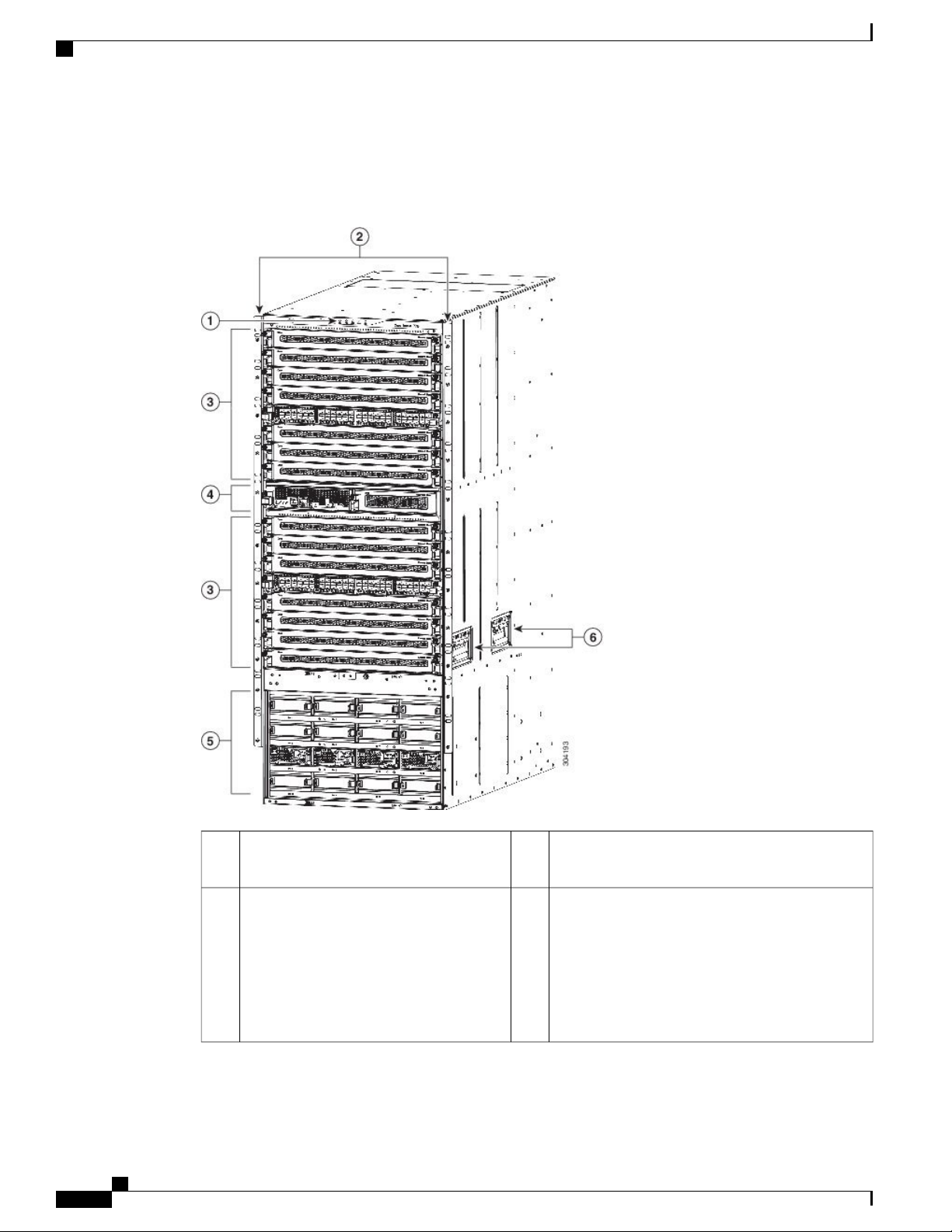
the standard hardware features seen from the front of the chassis.
Figure 1: Standard Hardware Features on the Front of the Cisco Nexus 7718 Chassis
Overview
Supervisor modules (one or two) (N77-SUP2E) in
4Chassis LEDs1
Slots 9,10
Power supplies (up to 16)
2
side of the chassis)
5Chassis mounting brackets (one on each
3-kW AC power supply (N77-AC-3KW)
•
3-kW DC power supply (N77-DC-3KW)
•
3.5-kW HVAC/HVDC power supply
•
(N77-HV-3.5KW)
Cisco Nexus 7718 Switch Site Preparation and Hardware Installation Guide
2 OL-30453-01
Page 13

Overview
3
I/O modules (1–16) in Slots 1-8, 11-18
48-port 1- and 10-Gigabit Ethernet
•
I/O module (N77-F248XP-23E)
48-port 1- and 10-Gigabit Ethernet
•
I/O module (N77-F348XP-23)
48-port 1- and 10-Gigabit Ethernet
•
I/O module (N77-M348XP-23L)
24-port 40-Gigabit Ethernet I/O
•
module (N77-F324FQ-25)
24-port 40-Gigabit Ethernet I/O
•
module (N77-M324FQ-25L)
12-port 100-Gigabit Ethernet I/O
•
module (N77-F312CK-26)
12-port 100-Gigabit Ethernet I/O
•
module (N77-M312CQ-26L)
Overview of the Cisco Nexus 7718 Switch Installation Features
Chassis handles (used only for small movements
6
on the rack)
Cisco Nexus 7718 Switch Site Preparation and Hardware Installation Guide
OL-30453-01 3
Page 14
Overview of the Cisco Nexus 7718 Switch Installation Features
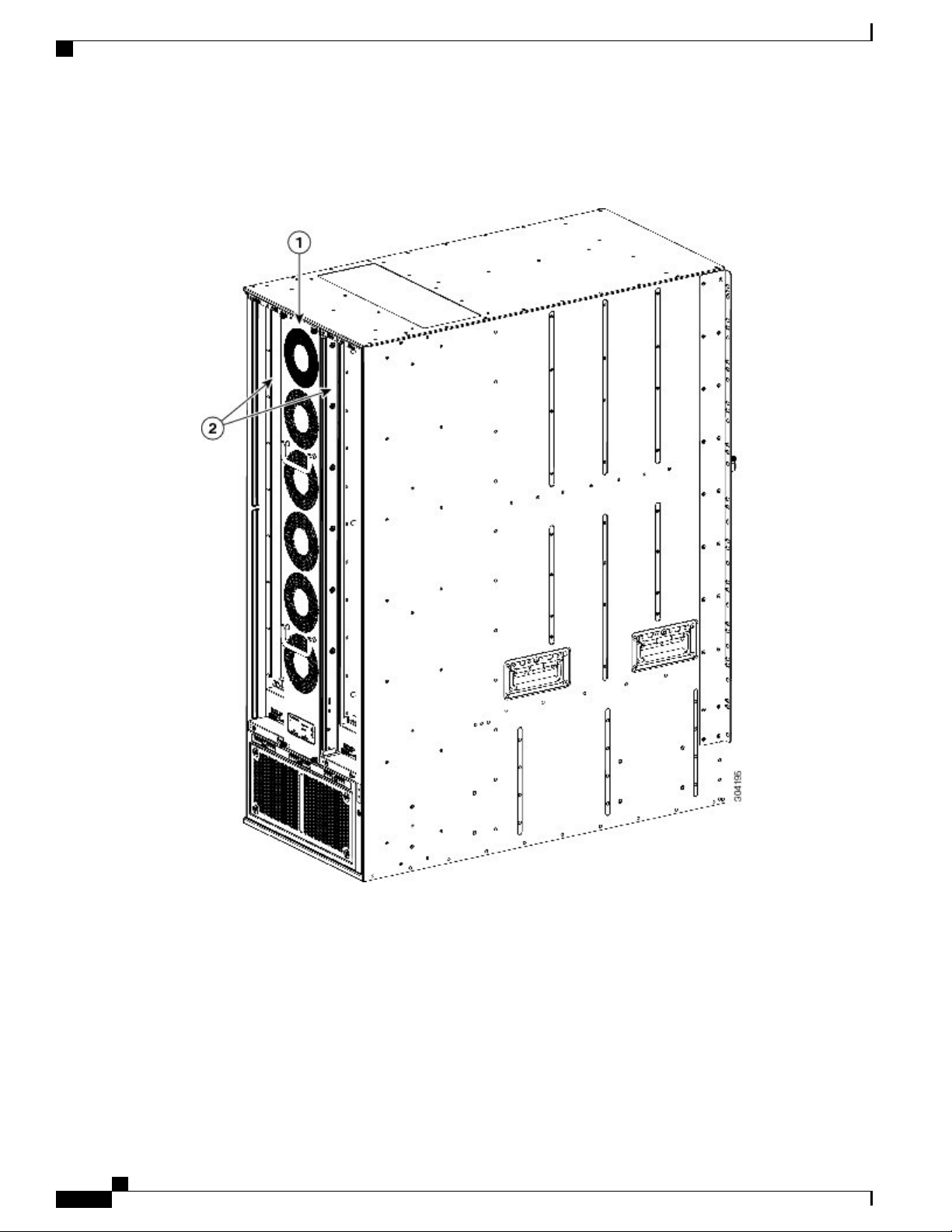
The following figure shows the standard hardware features seen from the rear of the chassis.
Figure 2: Standard Hardware Features on the Rear of the Cisco Nexus 7718 Chassis
Overview
Cisco Nexus 7718 Switch Site Preparation and Hardware Installation Guide
4 OL-30453-01
Page 15
Overview
Overview of the Cisco Nexus 7718 Switch Installation Features
1
Three fan trays — only 1 fan tray,
N77-C7718-FAN, is shown in this figure to
show fabric modules in back. There are 2 types
of fan trays: 38 mm Gen 1 fan trays
(N77-C7718-FAN) and 76 mm Gen 2 fan trays
(N77-C7718-FAN-2). Use the Gen 2 fan trays
for Network Equipment Building System
(NEBS) compliance when the Cisco Nexus
7700 M3-Series 12-port 100-Gigabit Ethernet
I/O module (N77-M312CQ-26L) is installed
on the switch.
2
fan tray) (N77-C7718-FAB-2)
Blank module in place of missing fabric module3
Fabric and fan tray LEDs4Fabric modules (up to six with two behind each
Cisco Nexus 7718 Switch Site Preparation and Hardware Installation Guide
OL-30453-01 5
Page 16
Overview of the Cisco Nexus 7718 Switch Installation Features
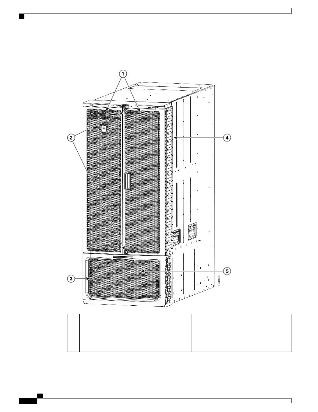
The following figure shows the optional features seen on the front of the Cisco Nexus 7718 chassis.
Figure 3: Optional Hardware Features on the Front of the Cisco Nexus 7718 Chassis
Overview
Air filter (N77-C7718-AFLT) inside each of
4Front doors with locks (N77-C7718-FDK)1
the top two front doors (filters not shown),
between each door and the cable management
frame (not shown), and over the cable
management frames (shown).
Cisco Nexus 7718 Switch Site Preparation and Hardware Installation Guide
6 OL-30453-01
Page 17

Overview
2
management area
Power supply door (N77-C7718-FDK)3
Overview of the Cisco Nexus 7718 Switch Installation Features
Power supply cable management frames (not
5Locks to prevent access to the cable
seen behind the power supply door).
Cisco Nexus 7718 Switch Site Preparation and Hardware Installation Guide
OL-30453-01 7
Page 18

Overview of the Cisco Nexus 7718 Switch Installation Features
Overview
Cisco Nexus 7718 Switch Site Preparation and Hardware Installation Guide
8 OL-30453-01
Page 19

CHAPTER 2
Preparing the Site
This chapter includes the following sections:
Humidity Requirements, page 9
•
Altitude Requirements, page 9
•
Dust and Particulate Requirements, page 10
•
Minimizing Electromagnetic and Radio Frequency Interference, page 10
•
Shock and Vibration Requirements, page 11
•
Grounding Requirements, page 11
•
Planning for Power Requirements, page 11
•
Rack and Cabinet Requirements, page 14
•
Clearance Requirements, page 17
•
Humidity Requirements
High humidity can cause moisture to seep into the switch. Moisture can cause corrosion of internal components
and degradation of properties such as electrical resistance, thermal conductivity, physical strength, and size.
The switch is rated to operate at 8 to 80 percent relative humidity, with a humidity gradation of 10 percent
per hour.
The switch can withstand from 5 to 90 percent relative humidity. Buildings in which the climate is controlled
by air-conditioning in the warmer months and by heat during the colder months usually maintain an acceptable
level of humidity for the switch equipment. However, if the switch is located in an unusually humid location,
you should use a dehumidifier to maintain the humidity within an acceptable range.
Altitude Requirements
If you operate a switch at a high altitude (low pressure), the efficiency of forced and convection cooling is
reduced and can result in electrical problems that are related to arcing and corona effects. This condition can
also cause sealed components with internal pressure, such as electrolytic capacitors, to fail or to perform at a
Cisco Nexus 7718 Switch Site Preparation and Hardware Installation Guide
OL-30453-01 9
Page 20

Dust and Particulate Requirements
reduced efficiency. This switch is rated to operate at altitudes from –500 to 13,123 feet (–152 to 4,000 meters).
You can store the switch at altitudes of –1,000 to 30,000 feet (–305 to 9,144 meters).
Dust and Particulate Requirements
Exhaust fans cool power supplies and system fan trays cool switches by drawing in air and exhausting air out
through various openings in the chassis. However, fans also ingest dust and other particles, causing contaminant
buildup in the switch and increased internal chassis temperature. A clean operating environment can greatly
reduce the negative effects of dust and other particles, which act as insulators and interfere with the mechanical
components in the switch.
Preparing the Site
Note
If you are using this switch in a nonclean environment, you can order and install optional air fliters. These
air filters require that you also order the optional front door for the chassis.
In addition to regular cleaning, follow these precautions to avoid contamination of your switch:
Do not permit smoking near the switch.
•
Do not permit food or drink near the switch.
•
Minimizing Electromagnetic and Radio Frequency Interference
Electromagnetic interference (EMI) and radio frequency interference (RFI) from the switch can adversely
affect other devices such as radio and television (TV) receivers operating near the switch. Radio frequencies
that emanate from the switch can also interfere with cordless and low-power telephones. Conversely, RFI
from high-power telephones can cause spurious characters to appear on the switch monitor.
RFI is defined as any EMI with a frequency above 10 kHz. This type of interference can travel from the switch
to other devices through the power cable and power source or through the air like transmitted radio waves.
The Federal Communications Commission (FCC) publishes specific regulations to limit the amount of EMI
and RFI that can be emitted by computing equipment. Each switch meets these FCC regulations.
To reduce the possibility of EMI and RFI, follow these guidelines:
Cover all open expansion slots with a metal filler.
•
Always use shielded cables with metal connector shells for attaching peripherals to the switch.
•
When wires are run for any significant distance in an electromagnetic field, interference can occur between
the field and the signals on the wires and cause the following implications:
Bad wiring can result in radio interference emanating from the plant wiring.
•
Strong EMI, especially when it is caused by lightning or radio transmitters, can destroy the signal drivers
•
and receivers in the chassis and even create an electrical hazard by conducting power surges through
lines into equipment.
Cisco Nexus 7718 Switch Site Preparation and Hardware Installation Guide
10 OL-30453-01
Page 21

Preparing the Site
Shock and Vibration Requirements
Note
To predict and prevent strong EMI, you might need to consult experts in radio frequency interference
(RFI).
The wiring is unlikely to emit radio interference if you use twisted-pair cable with a good distribution of
grounding conductors. If you exceed the recommended distances, use a high-quality twisted-pair cable with
one ground conductor for each data signal when applicable.
If the wires exceed the recommended distances, or if wires pass between buildings, give special consideration
to the effect of a lightning strike in your vicinity. The electromagnetic pulse caused by lightning or other
high-energy phenomena can easily couple enough energy into unshielded conductors to destroy electronic
switches. You may want to consult experts in electrical surge suppression and shielding if you had similar
problems in the past.
Shock and Vibration Requirements
The switch is being shock- and vibration-tested for operating ranges, handling, and earthquake standards to
Network Equipment Building Standards (NEBS) Zone 4 per GR-63-Core.
Grounding Requirements
The switch is sensitive to variations in voltage supplied by the power sources. Overvoltage, undervoltage,
and transients (or spikes) can erase data from the memory or cause components to fail. To protect against
these types of problems, ensure that there is an earth-ground connection for the switch. You can connect the
grounding pad on the switch either directly to the earth-ground connection or to a fully bonded and grounded
rack.
You must provide the grounding cable to make this connection but you can connect the grounding wire to the
switch using a grounding lug that ships with the switch. Size the grounding wire to meet local and national
installation requirements. Depending on the power supply and system, a 12 AWG to 6 AWG copper conductor
is required for U.S. installations (for those installations, we recommend that you use commercially available
6 AWG wire). The length of the grounding wire depends on the proximity of the switch to proper grounding
facilities.
Note
You automatically ground the AC power supplies when you connect them to a power source, but you
cannot ground a 3-kW DC power supply. You must connect the chassis to the facility earth ground.
Planning for Power Requirements
To plan for the power requirements of a switch, you must determine each of the following:
Power requirements of the switch
•
Minimum number of power supplies required to power the switch and its components
•
Power mode to use and the number of additional power supplies required for that mode
•
Cisco Nexus 7718 Switch Site Preparation and Hardware Installation Guide
OL-30453-01 11
Page 22
Planning for Power Requirements
You must also ensure that the circuit used for the switch is dedicated to the switch to minimize the possibility
of circuit failure.
When you know the amount of power that is required for operations (available power) and redundancy (reserve
power), you can plan for the required number of input power receptacles with reach of the switch location.
Procedure
Preparing the Site
Step 1
Determine the power requirement for the switch by summing the maximum wattage for each installed module
(see the following table).
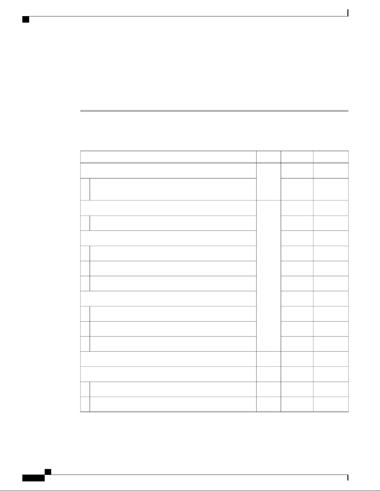
Table 1: Power Requirements for the Cisco Nexus 7718 Switch Modules
TypicalMaximumQuantityComponent
Supervisor Modules
1 or 2
——
(same
type if
137 W265 WSupervisor 2 Enhanced (N77-SUP2E)
using 2)
F2 I/O Modules
1 to 16
——
(can
mix
451 W500 W48-port 1- and 10-Gigabit Ethernet I/O module (N77-F248XP-23E)
types)
F3 I/O Modules
——
450 W480 W48-port 1- and 10-Gigabit Ethernet I/O module (N77-F348XP-23)
650 W740 W24-port 40-Gigabit Ethernet I/O module (N77-F324FQ-25)
640 W730 W12-port 100-Gigabit Ethernet I/O module (N77-F312CK-26)
M3 I/O Modules
——
500 W560 W48-port 1- and 10-Gigabit Ethernet I/O module (N77-M348XP-23L)
700 W750 W24-port 40-Gigabit Ethernet I/O module (N77-M324FQ-25L)
800 W1095 W12-port 100-Gigabit Ethernet I/O module (N77-M312CQ-26L)
102 W300 W3 to 6Fabric Modules (N77-C7718-FAB-2)
Fan Trays
———
51 W900 W338 mm Gen 1 Fan Tray (N77-C7718-FAN)
51 W900 W376 mm Gen 2 Fan Tray (N77-C7718-FAN-2)
Cisco Nexus 7718 Switch Site Preparation and Hardware Installation Guide
12 OL-30453-01
Page 23

Preparing the Site
Step 2
Planning for Power Requirements
For example, if you are installing a switch with two Supervisor 2 modules (2 x 265 W), 16 48-port 10-Gigabit
Ethernet I/O modules (PID: N77-F248XP-23E) (16 x 500 W), six fabric modules (6 x 300 W) and three fan
trays (3 x 900 W), the power requirements for this switch would be 13,030 W.
Note
Maximum power values are used for calculating the power
requirements.
Determine the number of power supplies needed for the available power requirement by dividing the power
requirement amount (see Step 1) by the output wattage of the power supplies installed in the switch.
For 3-kW power supplies, round up a fractional result to the nearest ones digit to determine the number of
power supplies needed.
For example, if you are installing a switch with 3-kW power supplies and have a consumption of 13,030 W,
you need five power supplies (13,030 W / 3000 W = 4.34 or 5 power supplies) to operate the switch and all
of its modules.
Step 3
Select one of the following power modes to determine the number of additional power supplies required for
reserve power:
• Combined power—Do not add any power supplies to the number of power supplies calculated for the
available power in Step 2. This power mode does not provide power redundancy, so no extra power
supplies are needed.
• Power supply redundancy (n+1 redundancy)—Add one power supply (reserve power supply). This form
of power redundancy provides a reserve power supply that can replace any active power supply that
goes offline.
• Input source redundancy (grid redundancy)—Add enough power supplies (reserve power supplies) to
at least equal the total output of the active power supplies (number of power supplies calculated in Step
2). Typically, you would double the number of power supplies. You must plan for a second power source
for the reserve power supplies. For example, if you calculate that you need two 3-kW power supplies
for 6 kW of available power, you need another two 3-kW power supplies for 6 kW of reserve power
(for a total of four 3-kW power supplies used for available and reserve power).
• Full redundancy (n+1 and grid redundancy)—Add enough power supplies (reserve power supplies) to
at least equal the output of the active power supplies (number of power supplies calculated in Step 2).
For power supply (n+1) redundancy, ensure that you have at least one extra power supply. For input-source
(grid) redundancy, you will probably double the number of power supplies. You must plan for a second
power source with at least the same amount of input power for the reserve power supplies. For example,
if you calculate that you need two 3-kW power supplies for 6 kW of active power, then you need another
two 3-kW power supplies for 6 kW of reserve power (for a total of four 3-kW power supplies used for
active and reserve power). Either one of the reserve power supplies can replace any of the active power
supplies.
Step 4
Be sure that the power source circuits are dedicated to the switch and not to other electrical equipment.
For combined power mode (no power redundancy) or power supply (n+1) redundancy, you need only one
dedicated circuit. For input-source (grid) or full redundancy, you must have two dedicated power circuits,
each circuit powering half of the 3-kWor 3.5-kW power supplies. The requirements for each circuit are listed
in the following table.
Cisco Nexus 7718 Switch Site Preparation and Hardware Installation Guide
OL-30453-01 13
Page 24
Rack and Cabinet Requirements
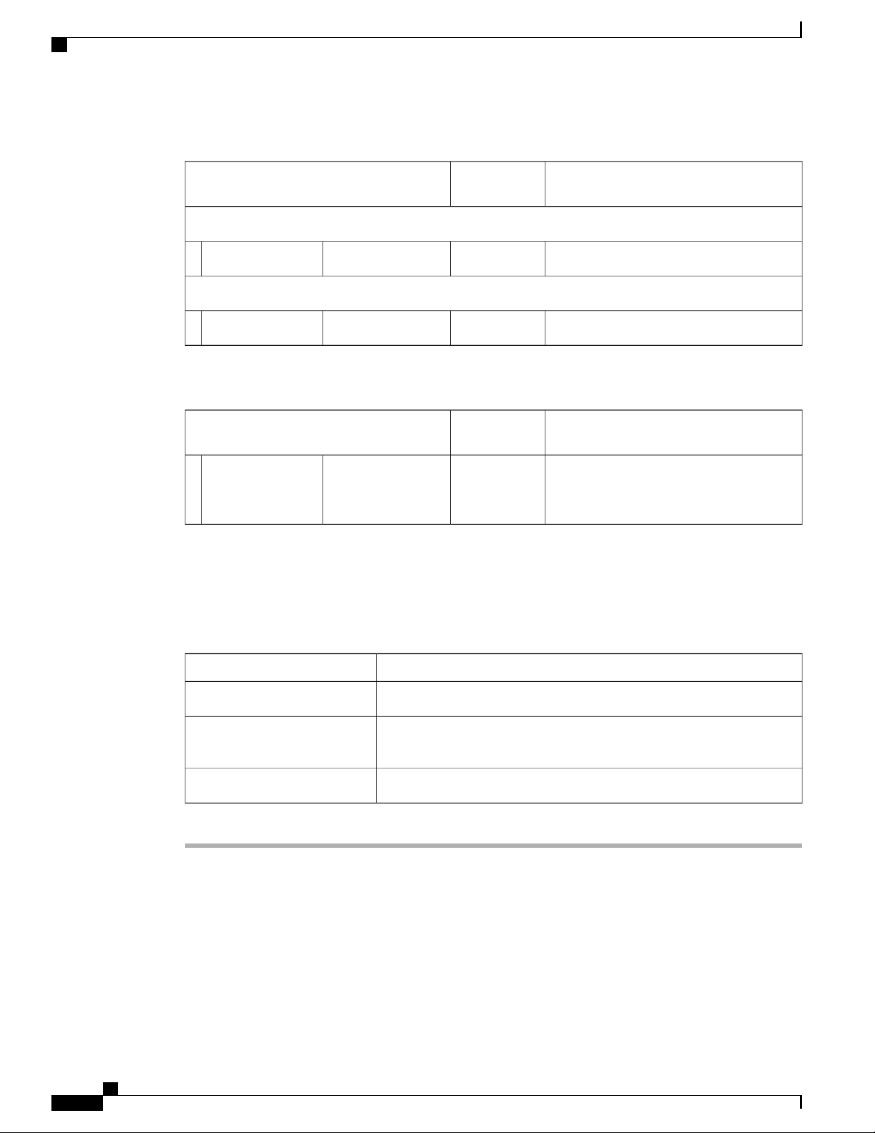
Table 2: Circuit Requirements for 3-kW Power Supplies
Preparing the Site
Step 5
Power Supply
Circuits
AC Power Supplies
DC Power Supplies
Table 3: Circuit Requirements for 3.5-kW HVAC/HVDC Power Supplies
Power Supply
Circuits
1(N77-HV-3.5KW)3.5-kW
HVAC/HVDC
power supply
Plan the placement of the input power receptacles within reach of the power cables used for each power supply
(see the following table for the maximum distances).
Typically, power receptacles are placed on the rack with the switch. If the DC power source is further than
allowed by the DC power cables, you can install a power interface unit (PIU) in the rack with the switch and
connect that to the power source with other cabling.
Requirement for Each CircuitNumber of
20 A at 110 VAC or 220 VAC1(N77-AC-3.0KW)3-kW power supply
20A1(N77-DC-3.0KW)3-kW power supply
Requirement for Each CircuitNumber of
20 A at 110 VAC, 210 VAC, 220/230 VAC
and 277 VAC or 20 A at 210 VDC, 220/240
VDC and 380 VDC
Maximum Distance Between Receptacle and Power SupplyPower Supply
12 feet (3.6 m)All AC power supplies
14 feet (4.26 m)HVAC/HVDC 3.5-kW power
supplies
Determined by the length of the power cord that you supply.DC 3-kW power supplies
Rack and Cabinet Requirements
You can install the following types of racks or cabinets for your switch:
Standard perforated cabinets
•
Cisco Nexus 7718 Switch Site Preparation and Hardware Installation Guide
14 OL-30453-01
Page 25

Preparing the Site
Solid-walled cabinets with a roof fan tray (bottom to top cooling)
•
Rack and Cabinet Requirements
Note
Installation clearance requirements for solid-wall cabinets are not in the scope of this
guide. Such installations have to be custom-engineered by a cooling professional. The
customised configuration should satisfy the requirements mentioned in the Preparing
the Site and the Switch Specifications sections.
Standard open four-post Telco racks
•
To correctly install the switch in a cabinet that is located in a hot-aisle/cold-aisle environment, you should fit
the cabinet with baffles to prevent exhaust air from recirculating into the chassis air intake.
Work with your cabinet vendors to determine which of their cabinets meet the following requirements or see
the Cisco Technical Assistance Center (TAC) for recommendations:
Use a standard 19-inch, four-post Electronic Industries Alliance (EIA) cabinet or rack with mounting
•
rails that conform to English universal hole spacing per section 1 of the ANSI/EIA-310-D-1992 standard.
The height of the rack or cabinet must accommodate the 26-RU (45.25 inches or 114.9 cm) height of
•
the switch and its bottom support bracket.
The depth of a four-post rack must be 24 to 32 inches (61.0 to 81.3 cm) between the front and rear
•
mounting brackets.
Required clearances between the chassis and the edges of its rack or the interior of its cabinet are as
•
follows:
7.5 inches (19.1 cm) is required between the chassis and the front of the rack or interior of the
◦
cabinet (required for cabling).
3.0 inches (7.6 cm) is required between the rear of the chassis and the perforated rear door of the
◦
cabinet (required for airflow inside the cabinet if used).
Note
This requirement does not apply to enclosures which have a solid rear door or wall with
other exhaust configurations.
No clearance is required between the chassis and the sides of the rack or cabinet (no side airflow).
◦
Additionally, you must consider the following site requirements for the rack:
Power receptacles must be located within reach of the power cords used with the switch.
•
AC power supplies
◦
Power cords for 3-kW AC power supplies are 8 to 12 feet (2.5 to 3.6 m) long.
◦
DC power supplies
◦
Power cords for 3.0-kW DC power supplies are supplied and dimensioned by the customer.
◦
HVAC/HVDC power supplies
◦
Cisco Nexus 7718 Switch Site Preparation and Hardware Installation Guide
OL-30453-01 15
Page 26

Rack and Cabinet Requirements
Clearance required for cables that connect to as many as 1600 ports (in addition to the cabling required
•
for other devices in the same rack). These cables must not block access to any removable chassis modules
or block airflow into or out of the chassis. Route the cables through the cable management frames on
the left and right sides of the chassis.
Where necessary, have a seismic rating of Network Equipment Building Standards (NEBS) Zone 3 or
•
Zone 4, per GR-63-CORE if required.
Minimum gross load rating of 2000 lb (907.2 kg) (static load rating) if supporting two switches.
•
Preparing the Site
Power cords for 3.5-kW HVAC/HVDC power supplies are 14 feet (4.26 m) long.
◦
1
1
Currently undergoing NEBS testing.
Cisco Nexus 7718 Switch Site Preparation and Hardware Installation Guide
16 OL-30453-01
Page 27
Preparing the Site
Clearance Requirements
You must provide the chassis with adequate clearance between the chassis and any other rack, device, or
structure so that you can properly install the chassis, route cables, provide airflow, and maintain the switch.
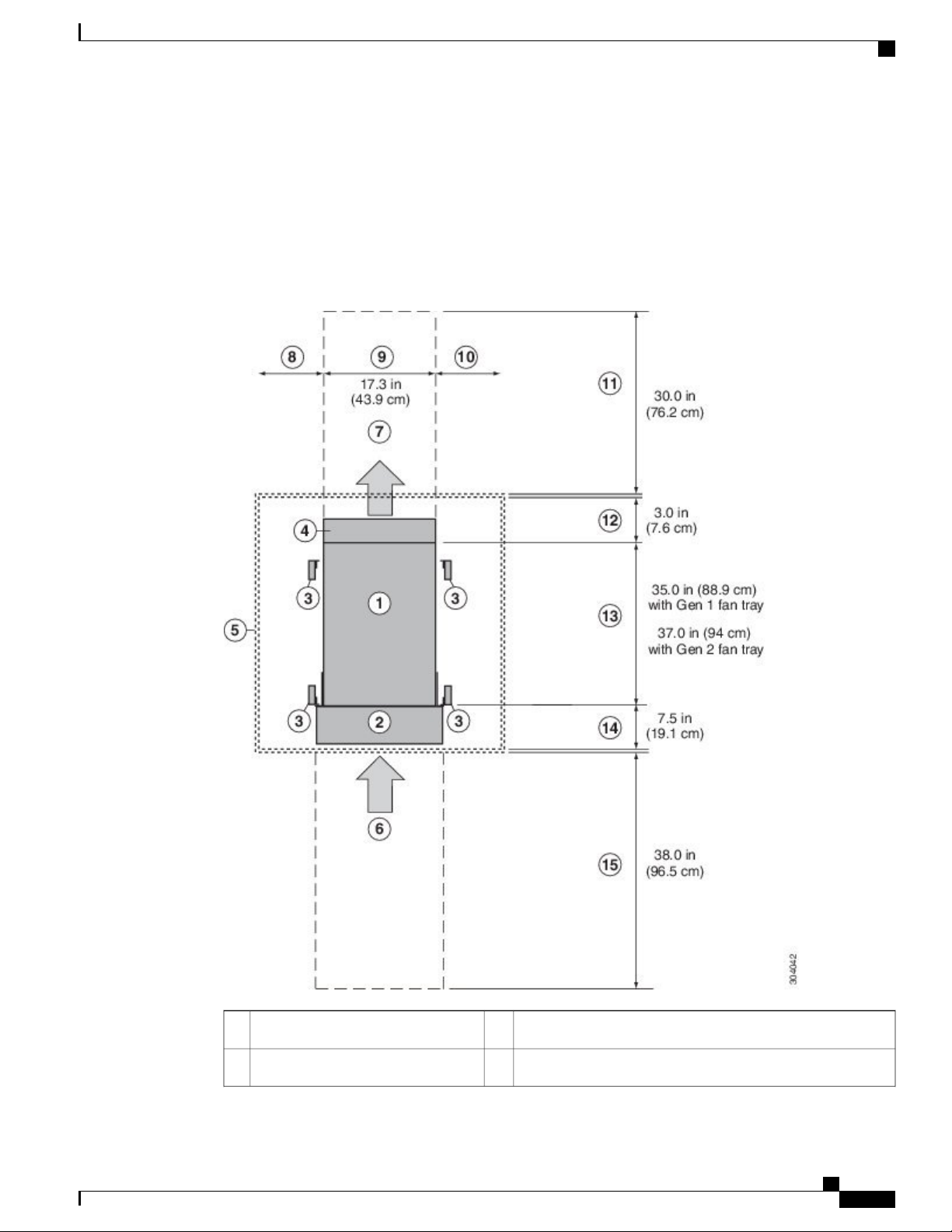
For the clearances required for an installation of this chassis, see the following figure.
Figure 4: Clearances Required for the Chassis
Clearance Requirements
Chassis width9Chassis1
No right side clearance required (no airflow on right side)10Cable management frames2
Cisco Nexus 7718 Switch Site Preparation and Hardware Installation Guide
OL-30453-01 17
Page 28

Clearance Requirements
4
5
6
7
(allow 2 inches [5 cm])
(no side clearance required)
modules and power supplies
modules and power supplies
Preparing the Site
Rear service clearance required to replace fan trays and fabric
11Vertical rack-mount posts and rails3
modules
Airflow clearance required between the chassis and inside
12Area required for fan tray handles
of cabinet (if used)
Chassis depth
13Nearest object or inside of cabinet
Note
The chassis depth will increase by 2 inches when
the 76mm Gen 2 fan tray (N77-C7718-FAN-2) is
used.
Clearance required between the front of the chassis and the
14Air intake from cold aisle for all
inside of the cabinet (if used) or edge of cold aisle (if no
cabinet) for the cable management frames and the optional
front doors
Front service clearance required for installing the chassis and
15Air exhaust to hot aisle for all
replacing the modules
Note
No left side clearance required (no
8
airflow on left side)
Figure 4: Clearances Required for the Chassis , on page 17 shows the clearance requirements for
conventional cold-aisle to hot-aisle systems which include rack enclosures with perforated front and rear
doors. The information given above does not apply to enclosures which have a solid rear or front door or
wall with other inlet or exhaust configurations. We recommend consulting a cooling professional if a solid
rear or front door is used.
Cisco Nexus 7718 Switch Site Preparation and Hardware Installation Guide
18 OL-30453-01
Page 29

Installing the Chassis
This chapter includes the following topics:
Installing a Rack or Cabinet, page 19
•
Unpacking and Inspecting a New Switch, page 20
•
Installing the Bottom-Support Rails , page 21
•
Installing a Chassis in a Rack or Cabinet, page 24
•
Grounding a Switch Chassis, page 32
•
Installing Cable Management Frames, page 40
•
Installing the Front Doors, page 46
•
Installing the Air Filters, page 48
•
CHAPTER 3
Installing a Rack or Cabinet
Before you install the switch, you must install a standard four-post, 19-inch EIA data center rack (or a cabinet
that contains such a rack) that meets the requirements listed in Rack and Cabinet Requirements.
Procedure
Step 1
Step 2
Step 3
OL-30453-01 19
Bolt the rack to the concrete subfloor before moving the chassis onto it.
Warning
Statement 1048
If the rack has bonded construction, connect it to the earth ground. This action enables you to easily ground
the switch and its components and to ground your electrostatic discharge (ESD) wrist strap to prevent damaging
discharges when you handle ungrounded components before installing them.
If you need access to the source power at the rack, include either AC power receptacles or a DC power interface
unit (PIU) with the amperage required by the switch that you are installing. .
Stability hazard. The rack stabilizing mechanism must be in place, or the rack must be bolted to
the floor before you slide the unit out for servicing. Failure to stabilize the rack can cause the rack
to tip over.
Cisco Nexus 7718 Switch Site Preparation and Hardware Installation Guide
Page 30
Unpacking and Inspecting a New Switch
If you are using DC power, be sure that the DC power supply is grounded and that there is direct access to
the facility DC power or indirect access though a power interface unit (PIU). You must connect the DC power
supply to the earth ground before you connect it to the facility DC power.
Take care when connecting units to the supply circuit so that wiring is not overloaded.Warning
Statement 1018
Note
If you are using the combined power mode or power-supply redundancy, you need only one power
source. If you are using input-source redundancy or full redundancy, you need two power sources.
Unpacking and Inspecting a New Switch
Before you install a new chassis, you need to unpack and inspect it to be sure that you have all the items that
you ordered and verify that the switch was not damaged during shipment. If anything is damaged or missing,
contact your customer representative immediately.
Installing the Chassis
Caution
Tip
Step 1
When you handle the chassis or its components, you must follow ESD protocol at all times to prevent
ESD damage. This protocol includes but is not limited to wearing an ESD wrist strap that you connect to
the earth ground.
Do not discard the shipping container when you unpack the switch. Flatten the shipping cartons and store
them with the pallet used for the system. If you need to move or ship the system in the future, you will
need these containers.
Procedure
Compare the shipment to the equipment list that is provided by your customer service representative and
verify that you have received all of the ordered items.
The shipment should include boxes for the following:
System chassis, which includes the following installed components:
•
1 or 2 supervisor modules
◦
1 to 16 I/O modules
◦
Up to 6 fabric modules
◦
3 fan trays
◦
1 to 16 power supply units
◦
Switch accessory kit
•
To see a list of what is included in this kit, see Accessory Kit Contents, on page 199.
Cable management frames
•
Cisco Nexus 7718 Switch Site Preparation and Hardware Installation Guide
20 OL-30453-01
Page 31

Installing the Chassis
Left and right side frames
◦
Top frame
◦
M4 x 12 mm flat-head Phillips screws (12)
◦
• Front door kit — Optional (N77-C7718-FDK)
Front door (1) (69-2532-01)
◦
M3 x 8 mm pan-head screws (2) (48-0393-01)
◦
• Air filter kit — Optional (N77-C7718-AFLT)
Air filter (1) for the front door
◦
Door-side brush filters (2)
◦
Cable-management frame brush filters (2)
◦
M4 x 12 mm flat-head Phillips screws (12)
◦
Installing the Bottom-Support Rails
Step 2
Step 3
Check the contents of each box for damage.
If you notice any discrepancies or damage, send the following information to your customer service
representative by email:
Invoice number of the shipper (see the packing slip)
•
Model and serial number of the missing or damaged unit
•
Description of the problem and how it affects the installation
•
Installing the Bottom-Support Rails
The bottom-support rails support the chassis in the rack or cabinet. To maximize the stability of the rack, you
must attach these rails at the lowest possible rack unit (RU). If anything lighter than the switch is already
installed in the rack, you should make sure that it is positioned above where you will be installing the switch.
Cisco Nexus 7718 Switch Site Preparation and Hardware Installation Guide
OL-30453-01 21
Page 32

Installing the Bottom-Support Rails
Installing the Chassis
Warning
Step 1
To prevent bodily injury when mounting or servicing this unit in a rack, you must take special precautions
to ensure that the system remains stable. The following guidelines are provided to ensure your safety:
This unit should be mounted at the bottom of the rack if it is the only unit in the rack.
•
When mounting this unit in a partially filled rack, load the rack from the bottom to the top with the
•
heaviest component at the bottom of the rack.
If the rack is provided with stabilizing devices, install the stabilizers before mounting or servicing
•
the unit in the rack.
Statement 1006
To attach the bottom-support rails to a four-post EIA rack, follow these steps:
Before You Begin
Before you can install the bottom support rails, make sure that you have done each of the following:
Installed a four-post rack or cabinet (see Installing a Rack or Cabinet).
•
Unpacked and inspected the chassis shipment.
•
Procedure
Position one of the two adjustable bottom-support rails at the lowest possible RU in the rack or cabinet. Adjust
the length of the rail so that it stretches from the outer edges of the front and rear vertical mounting rails. You
Cisco Nexus 7718 Switch Site Preparation and Hardware Installation Guide
22 OL-30453-01
Page 33

Installing the Chassis
Installing the Bottom-Support Rails
can expand the rail so that its mounting brackets are spaced between 24 to 32 inches (61.0 to 81.3 cm). See
the following figure.
Figure 5: Positioning Bottom-Support Rails for a Cisco Nexus 7718 Chassis
1
2Position two bottom-support rails at the
lowest RU on the rack.
Cisco Nexus 7718 Switch Site Preparation and Hardware Installation Guide
OL-30453-01 23
Allow at least 45.5 inches (115.6 cm) (26 RU)
for each Cisco Nexus 7718 chassis.
Page 34

Installing a Chassis in a Rack or Cabinet
Installing the Chassis
Step 2
Attach the bottom-support rail to the rack or cabinet. Use a Phillips screwdriver to screw in four M6 x 19 mm
or 12-24 x 3/4 inch Phillips screws on each end of the rail (using a total of 8 screws for the rail) as shown in
the following figure. Tighten each screw to 40 in. lbs (4.5 N.m) of torque.
Figure 6: Attaching Bottom-Support Rails to a Rack
1
(8 per rail)
Step 3
Repeat the first two steps to attach the other bottom-support rail to the other side of the rack.
Note
Make sure that the two bottom-support rails are level with one another. If they are not level, adjust
the higher rail down to the level of the lower rail.
What to Do Next
When the bottom-support rails are installed at the lowest possible RU and are level, you are ready to install
the chassis in the rack or cabinet.
Installing a Chassis in a Rack or Cabinet
To move a chassis to a rack, it is necessary to slide the chassis onto a mechanical lift, use that mechanical lift
to position the chassis in front of its place on the rack, slide the chassis from the lift to the rack, and then bolt
the chassis to the rack. You can make the chassis easier to move if you remove the power supplies, fan trays,
and fabric modules. These modules are sealed to minimize the chance of being damaged by electrostatic
discharge (ESD), so you can remove them from the chassis to make the chassis easier to move.
Adjustable bottom-support rails (2)2M6 x 19 mm (or 12-24 x 3/4 in.) Phillips screws
Cisco Nexus 7718 Switch Site Preparation and Hardware Installation Guide
24 OL-30453-01
Page 35

Installing the Chassis
Before You Begin
You have fully installed a rack or cabinet (see Installing a Rack or Cabinet).
•
Installing a Chassis in a Rack or Cabinet
Note
Stability hazard. The rack stabilizing mechanism must be in place, or the rack must be
bolted to the floor before you slide the unit out for servicing. Failure to stabilize the
rack can cause the rack to tip over. Statement 1048
You have installed the bottom-support rails to the lowest possible RU in the rack and there is at least 25
•
RU (43.75 inches [111 cm]) of space above the rails to install the chassis.
Data center ground is accessible where you are installing the chassis.
•
If there are other devices in the rack, you have arranged the heavier devices below lighter devices, and
•
all devices are installed as low as possible with spacing left for the switch chassis.
You have unpacked and inspected the chassis shipment for completeness and damage.
•
You have the following tools and equipment:
•
Mechanical lift capable of lifting the weight of the chassis and the modules, fan trays, and power
◦
supplies installed in it. Fully loaded, the switch weighs up to 923 lb (419 kg). If you remove the
units protected from ESD damage (power supplies, fan trays, and fabric modules), the maximum
weight of the chassis is 586 lb (266 kg). To determine the full weight of your chassis with its
modules installed (or the weight if you remove the protected modules), see Weights and Quantities
for the Chassis, Modules, Fan Trays, and Power Supplies, on page 145.
You must use a mechanical lift to lift anything weighing over 120 pounds (55 kg).Caution
Note
Number 1 Phillips-head torque screwdriver
◦
18 12-24 x 3/4-inch or M6 x 19 mm Phillips screws from the bottom-support rails kit
◦
You should also have at least three persons to move the chassis, which can weigh up to 923 pounds (449
kg), onto and off the mechanical lift and rack.
Cisco Nexus 7718 Switch Site Preparation and Hardware Installation Guide
OL-30453-01 25
Page 36

Installing a Chassis in a Rack or Cabinet
Installing the Chassis
Warning
Step 1
To prevent bodily injury when mounting or servicing this unit in a rack, you must take special precautions
to ensure that the system remains stable. The following guidelines are provided to ensure your safety:
This unit should be mounted at the bottom of the rack if it is the only unit in the rack.
•
When mounting this unit in a partially filled rack, load the rack from the bottom to the top with the
•
heaviest component at the bottom of the rack.
If the rack is provided with stabilizing devices, install the stabilizers before mounting or servicing
•
the unit in the rack.
Statement 1006
Procedure
If you need to make the chassis as light as possible for moving, remove the following modules and place them
where their connectors will not be damaged:
• Power supplies—For each power supply, press and hold the eject lever, and use the handle on the front
of the power supply to pull the power supply out of the chassis.
• Fan trays—Unscrew the four captive screws, and use the two handles on the fan tray to pull the fan tray
out of the chassis.
• Fabric modules—For each fabric module, keep your face at least 12 inches (30 cm) away from the
modules, press both eject buttons on the front, rotate both levers away from the front of the module, use
the levers to pull the module out of the chassis.
Step 2
Load the chassis onto a mechanical lift as follows:
a) Position the mechanical lift next to the shipping pallet that holds the chassis.
b) Elevate the lift platform to the level of the bottom of the chassis (or no more than 1/4 inch [0.635 cm]
below the bottom of the chassis).
c) Use at least four persons to slide the chassis fully onto the lift so that the side of the chassis touches or is
close to the vertical rails on the lift. Make sure that the front and rear of the chassis are unobstructed so
you can easily push the chassis into the rack.
Warning
To prevent personal injury or damage to the chassis, never attempt to lift or tilt the chassis using
the handles on modules (such as power supplies, fans, or cards); these types of handles are not
designed to support the weight of the unit. Statement 1032
Caution
To lift the chassis, use a mechanical lift, not the handles on the side of the chassis (the handles are
not rated for lifting over 200 pounds [91 kg]). Use the side handles for only repositioning the
chassis after it is already on the mechanical lift or in the rack or cabinet.
Cisco Nexus 7718 Switch Site Preparation and Hardware Installation Guide
26 OL-30453-01
Page 37

Installing the Chassis
Installing a Chassis in a Rack or Cabinet
Step 3
Step 4
Step 5
Use the mechanical lift to position the chassis in front of the four-post rack or cabinet and elevate the chassis
to the level of the bottom-support rails or no more than 1/4 inch (0.6 cm) above the bracket.
Make sure that the chassis is positioned with the rear (the side with the open power supply slots) ready to go
into the rack or cabinet first. If necessary, you can use the two handles on either side of the chassis to move
the chassis on the lift.
Use two persons to push the chassis halfway onto the rack or cabinet and use one person to guide the chassis
down the bottom-support brackets while making sure that the chassis does not get caught on any edges of the
bottom support brackets.
Cisco Nexus 7718 Switch Site Preparation and Hardware Installation Guide
OL-30453-01 27
Page 38

Installing a Chassis in a Rack or Cabinet
Push only the lower front sides of the chassis—do not push on any modules and do not use any module handles
to move the chassis.
Figure 7: Moving the Chassis onto a Rack or Cabinet
Installing the Chassis
1
3Push the sides of the lower half of the front side of the chassis
(do not push on any of the modules or module handles).
Rack vertical mounting
rails.
Chassis mounting brackets.2
Cisco Nexus 7718 Switch Site Preparation and Hardware Installation Guide
28 OL-30453-01
Page 39

Installing the Chassis
Installing a Chassis in a Rack or Cabinet
Step 6
Step 7
Step 8
If the mechanical lift is raised above the bottom-support brackets, gently lower the lift to the level of the
brackets or no more than 1/4 inch (0.6 cm) below the brackets.
This keeps the chassis level on the brackets and helps prevent the chassis from getting caught on the inside
edges of the bottom-support brackets.
Use two persons to fully push the chassis all the way onto the rack or cabinet.
You have pushed the chassis all the way when its two vertical mounting brackets come in contact with the
vertical rails on the rack or cabinet.
Align the mounting bracket on the chassis to the vertical mounting rails on the rack, and attach the chassis to
the rack.
Align the screw holes in the chassis mounting brackets to the screw holes in the vertical mounting rails on
the rack or cabinet. Use a Phillips screwdriver to screw in nine M6 x 19-mm or 12-24 x 3/4-inch screws in
each of the two chassis mounting brackets (use a total of 18 screws for two mounting brackets). See the
following figure.
Cisco Nexus 7718 Switch Site Preparation and Hardware Installation Guide
OL-30453-01 29
Page 40

Installing a Chassis in a Rack or Cabinet
To adjust the placement of the chassis on the bottom-support rails, use the chassis handles shown in
Tip
the following figure.
Figure 8: Attaching the Chassis to the Rack
Installing the Chassis
1
2Handles used to adjust the chassis
placement
Nine M6 x 19 mm or 10-24 x 3/4 in. Phillips screws used
to attach each side bracket to a front mounting rail (use a
total of 18 screws)
Step 9
If you removed any fabric modules before moving the chassis, replace each one in the chassis as follows:
a) Holding the front of the fabric module (the side with the LEDs), turn the module so that the front side is
vertical.
Cisco Nexus 7718 Switch Site Preparation and Hardware Installation Guide
30 OL-30453-01
Page 41

Installing the Chassis
Installing a Chassis in a Rack or Cabinet
Step 10
Step 11
Note
The top of the module has an alignment bracket running from the rear to the front. The electrical
connectors will be at the bottom.
b) Align the rear of the fabric module to an open fabric slot and insert the bracket on top of the module in
the track at the top of the slot.
Note
If there are only three fabric modules to install, install them in fabric slots 1, 3, and
5.
c) Slide the module part way into the slot.
d) Unscrew the captive screw on each of two ejector levers on the front of the module and rotate the two
levers away from the module.
e) Holding the levers, slide the module all the way into the slot until it stops.
f) Simultaneously rotate both levers to the front of the module and secure them to the module by screwing
their captive screws to the module. Tighten each screw to 8 in-lb (0.9 N·m).
If you removed any fan trays before moving the chassis, reinstall each one in the chassis as follows:
a) Holding each of the two handles on the fan tray with your two hands, align the fan tray to an open fan tray
slot.
Note
The two alignment brackets on top of the fan tray should align to two tracks at the top of the
slot.
b) Slide the fan tray into the slot until the front of the fan tray comes in contact with the rear of the chassis.
Note
The two alignment pins on the fan tray (on the top and one on the bottom) should go into holes
in the chassis and the four captive screws on the fan tray should align to screw holes in the chassis.
c) Screw in the four captive screws to the chassis and tighten each screw to 8 in-lb (0.9 N·m).
If you removed any power supplies before moving the chassis, reinstall each one as follows:
a) Determine which power supply slots to fill and ensure that each of those slots is open.
If you are using the combined or power supply redundancy mode, you can use any slot for the power
supply that you are installing. If you are using input-source or full redundancy mode, you must group the
power supplies that are to be connected to the same grid on either the left or right power supply slots in
the chassis (that is, place the power supplies for grid A in slots 1, 2, 5, or 6 and place the power supplies
for grid B in slots 3, 4, 7, or 8).
Step 12
b) Place one hand on the front of the power supply and place your other hand under it to support its weight.
c) Align the power supply to an open power supply slot.
Note
The alignment bracket on top of the power supply should align to a track at the top of the slot
and a bar at the bottom of the power supply should be guided by a track at the bottom of the slot.
d) Slide the power supply all the way into the slot until it stops.
e) Slide the handle in the middle of the ejector lever toward the end of the lever and rotate the lever to the
front of the power supply. Release the middle handle.
Note
The lever should grab the inside of the slot and push the power supply onto its mid plane
connectors.
f) Screw in the two captive screws on the front of the power supply to the chassis. Tighten each screw to 8
in-lb (0.9 N·m).
Connect each installed power supply with an AC power circuit as follows:
Note
If you are using combined power mode (no power redundancy) or power supply (n+1) power mode,
connect all of the power supplies to the same power circuit (grid). If you are using input source (n+n)
or full power mode, connect half of the power supplies (located in slots 1, 2, 5, 6, 9, 10, 13, and 14)
to one AC power circuit and the other half of the power supplies (located in slots 3, 4, 7, 8, 11, 12,
15, and 16) to another AC power circuit. When you connect each power supply to an AC power
circuit, the LEDs on the power supply turn on. The switch can operate when each of the required
power supplies have a green OUTPUT LED lit.
Cisco Nexus 7718 Switch Site Preparation and Hardware Installation Guide
OL-30453-01 31
Page 42

Grounding a Switch Chassis
a) Ensure that the power supply is turned off by making sure that the power switch is set to 0.
b) Connect the power cable that shipped with the power supply to the AC power source.
c) Connect the other end of the power cable to the power supply outlet.
What to Do Next
After the chassis is secured to the rack, you can ground the switch (see Grounding a Switch Chassis, on page
32).
Grounding a Switch Chassis
The switch is fully grounded as soon as you connect the chassis and the power supplies to the earth ground
in the following ways:
You connect the chassis to either a fully-bonded, grounded rack or to the data center ground.
•
Installing the Chassis
Note
You connect the AC and HVAC/HVDC power supplies to the earth ground automatically when you
•
connect an AC or HVAC/HVDC power supply to an AC or HVAC/HVDC power source.
The system ground, also referred to as the network equipment building system (NEBS)
ground, provides additional grounding for EMI shielding requirements and for the
low-voltage supplies (DC-DC converters) on the modules. This grounding system is
active even when the AC and HVAC/HVDC power cables are not connected to the
system.
Before You Begin
Before you can ground the chassis, you must have a connection to the earth ground for the data center building.
If you installed the switch chassis into a bonded rack (see the rack manufacturer's instructions for more
information) that now has a connection to the data center earth ground, you can ground the chassis by connecting
its grounding pad to the rack. Otherwise, you must connect the chassis grounding pad directly to the data
center ground.
To connect the switch chassis to the data center ground, you need the following tools and materials:
• Grounding lug—A two-holed standard barrel lug that supports up to 6 AWG wire. This lug is supplied
with the accessory kit.
• Grounding screws—Two M4 x 8 mm (metric) pan-head screws. These screws are shipped with the
accessory kit.
• Grounding wire—Not supplied with the accessory kit. This wire should be sized to meet local and
national installation requirements. Depending on the power supply and system, a 12 AWG to 6 AWG
copper conductor is required for U.S. installations. We recommend that you use commercially available
6 AWG wire. The length of the grounding wire depends on the proximity of the switch to proper grounding
facilities.
Number 1 manual Phillips-head torque screwdriver.
•
Crimping tool to crimp the grounding wire to the grounding lug.
•
Cisco Nexus 7718 Switch Site Preparation and Hardware Installation Guide
32 OL-30453-01
Page 43

Installing the Chassis
Wire-stripping tool to remove the insulation from the grounding wire.
•
Procedure
Grounding a Switch Chassis
Step 1
Step 2
Step 3
Step 4
Use a wire-stripping tool to remove approximately 0.75 inch (19 mm) of the covering from the end of the
grounding wire.
Insert the stripped end of the grounding wire into the open end of the grounding lug as shown in the following
figure.
Figure 9: Inserting a Grounding Wire in a Grounding Lug
1
2NRTL listed 45-degree grounding
lug
Grounding cable with 0.75 in. (19 mm) of insulation
stripped from one end
Use the crimping tool to crimp the lug to the grounding wire. Verify that the ground wire is securely attached
to the grounding lug by attempting to pull the wire out of the crimped lug.
Secure the grounding wire lug to the grounding pad with two M4 screws, and tighten the screws to 11.5 to
15 in-lb (1.3 to 1.7 N·m) of torque.
Cisco Nexus 7718 Switch Site Preparation and Hardware Installation Guide
OL-30453-01 33
Page 44

Grounding a Switch Chassis
The following figure shows the location of the grounding pad on the front of the chassis. There is another
grounding pad on the other side of the chassis.
Figure 10: Grounding Pad Location on the Front of the Cisco Nexus 7718 Chassis
Installing the Chassis
Grounding pad1
Step 5
Prepare the other end of the grounding wire and connect it to an appropriate grounding point in your site to
ensure an adequate earth ground for the switch. If the rack is fully bonded and grounded, connect the grounding
wire as explained in the documentation provided by the vendor for the rack.
Cisco Nexus 7718 Switch Site Preparation and Hardware Installation Guide
34 OL-30453-01
Page 45

Installing the Chassis
Grounding the Front ID Doors
Grounding the Front ID Doors
Note
To comply with GR-1089, you have to bond the front industrial design (ID) doors to the ground port on
the chassis using the ground braid.
Figure 7 shows the two sections of the Cisco Nexus 7718 front ID doors. The upper two doors are used for
the I/O modules and the bottom door is used for the power supplies.
Figure 11: Front ID Door Sections
Door for power supplies2Doors for I/O modules1
Procedure
Step 1
OL-30453-01 35
Remove 7 screws from the front industrial design (ID) doors.
Cisco Nexus 7718 Switch Site Preparation and Hardware Installation Guide
Page 46

Grounding the Front ID Doors
Figure 8 shows the 7 screws (circled) that have to be removed.
Figure 12: Front ID Door
Installing the Chassis
Cisco Nexus 7718 Switch Site Preparation and Hardware Installation Guide
36 OL-30453-01
Page 47

Installing the Chassis
Grounding the Front ID Doors
Step 2
Install grounding cables to the left side of the power supply door, as shown in Figure 9, to connect the middle
plate with the top and bottom hinges.
Figure 13: Grounding Cable Locations on the Door for the Power Supplies
Flat washer2M4 screw1
Grounding cable4M4 screw3
Cisco Nexus 7718 Switch Site Preparation and Hardware Installation Guide
OL-30453-01 37
Page 48

Grounding the Front ID Doors
Installing the Chassis
Step 3
Step 4
Tighten the screw to 7 in-lb (0.79 N-m) of torque to provide proper bonding.
Connect the grounding cable from the door for the power supplies to the switch chassis, as shown in Figure
10.
Figure 14: Grounding Cable Location between the door for the Power Supplies and the Cisco Nexus 7718 switch chassis
M4 screw2M4 screw1
Grounding cable4Flat washer3
Cisco Nexus 7718 Switch Site Preparation and Hardware Installation Guide
38 OL-30453-01
Page 49

Installing the Chassis
Grounding the Front ID Doors
Step 5
Install a grounding cable between the left hand side door for the I/O modules and the switch chassis, as shown
in Figure 11. Repeat the procedure for installing a grounding cable between the right hand side door for the
I/O modules and the switch chassis.
Figure 15: Grounding Cable Location between the Left Hand Side Door for the I/O Modules and the Cisco Nexus 7718
Switch Chassis
Note
The grounding cable location for installing the grounding cable between the right hand side door for
the I/O modules and the Cisco Nexus 7718 switch chassis will be mirrored on the right hand side of
the switch.
M4 screw2Grounding cable1
Cisco Nexus 7718 Switch Site Preparation and Hardware Installation Guide
OL-30453-01 39
Page 50

Installing Cable Management Frames
Installing the Chassis
Step 6
Step 7
Apply the star ring terminal end of the grounding cables to the front ID doors.
Connect the other round terminal of the grounding cable to the ground port on the chassis, as shown in Figure
11. Tighten the M4 screw to 9 to 12 in-lb (1.01 to 1.35 N-m) of torque.
Installing Cable Management Frames
You install the middle cable management frame and then install the lower and upper frames on the middle
frame. After installing the cable management frames on the left and right sides of the front of the chassis, you
install the top hood, and then tighten the screws holding all the frames to the chassis.
If you are installing the optional front doors on the chassis, you must have the cable management frames
already installed because they hold the front doors to the chassis.
Before You Begin
The chassis is installed and secured to the rack or cabinet.
•
You have the following tools and equipment:
•
Phillips torque screwdriver (customer supplied).
◦
Following frames and screws (shipped with the switch):
◦
Two cable management upper side frames
◦
Two cable management middle side frames
◦
Step 1
Two cable management lower side frames
◦
One cable management top hood frame
◦
36 M4 x 13-mm, flat-head, Phillips screws
◦
Procedure
Attach the middle cable management frames as follows:
Cisco Nexus 7718 Switch Site Preparation and Hardware Installation Guide
40 OL-30453-01
Page 51

Installing the Chassis
Installing Cable Management Frames
a) Align the four screw holes in a middle cable management frame to four screw hole standoffs on one of
two brackets attached to the front of the chassis (see the following figure).
Figure 16: Attaching the Middle Cable Management Frame to the Chassis
Middle cable management frame with four
3Chassis mounting bracket1
screw holes
Four M4 x 13 mm screws that secure the middle
2
mounting bracket
4Four screw-hole standoffs on the chassis
cable management frame to the chassis
mounting bracket
Cisco Nexus 7718 Switch Site Preparation and Hardware Installation Guide
OL-30453-01 41
Page 52

Installing Cable Management Frames
b) Use four M4 x 13 mm screws to attach the frame to the bracket. Do not tighten the screws.
c) Repeat steps 1a and 1b to attach the other middle cable management frame to the other side of the chassis.
Installing the Chassis
Step 2
Attach the lower cable management frames as follows:
a) Position a lower cable management frame below the installed middle cable management frame and slide
the lower frame onto the flange at the bottom of the middle frame.
Verify that the two angle brackets on the frame are touching the front of the chassis and that the screw
holes in the brackets align with screw holes in the chassis. If not, remove this frame and replace it with
the other lower frame.
Figure 17: Attaching a Lower Cable Management Frame to the Chassis
Cisco Nexus 7718 Switch Site Preparation and Hardware Installation Guide
42 OL-30453-01
Page 53

Installing the Chassis
Installing Cable Management Frames
Two M4 x 13 mm screws to secure an angle bracket
4Chassis mounting bracket1
to the chassis
Two M4 x 13 mm screws to secure the frame to the
2
management frame
Middle cable management frame with
3
5Alignment flange on the middle cable
chassis mounting bracket
alignment groove on top, two screw
holes, and two angle brackets with two
screw holes each
b) Use two M4 x 13 mm screws to attach the frame to the vertical chassis mounting bracket. Do not tighten
the screws.
c) Use two M4 x 13 mm screws to attach each of the two angle brackets to the chassis (total of four screws).
Do not tighten the screws.
d) Repeat steps 2a, 2b, and 2c to attach the other lower cable management frame to the other side of the
chassis.
Step 3
Attach the upper cable management frames as follows:
a) Position the upper cable management frame above the installed middle cable management frame and slide
the upper frame onto the flange on the top of the middle frame (see the following figure).
Verify that the five screw holes on the frame align with five screw-hole standoffs on the chassis mounting
bracket.
Cisco Nexus 7718 Switch Site Preparation and Hardware Installation Guide
OL-30453-01 43
Page 54

Installing Cable Management Frames
Figure 18: Attaching an Upper Cable Management Frame to the Chassis
Installing the Chassis
Screw hole standoff (5)4Chassis mounting bracket1
Five M4 x 13 mm screws to secure the frame to the
2
management frame
Upper cable management frame with five
3
5Alignment flange on the middle cable
chassis mounting bracket
screw holes and an alignment groove on
the bottom
Cisco Nexus 7718 Switch Site Preparation and Hardware Installation Guide
44 OL-30453-01
Page 55

Installing the Chassis
Installing Cable Management Frames
b) Use five M4 x 13 mm screws to attach the frame to the bracket. Do not tighten the screws.
c) Repeat steps 3a and 3b to attach the other upper cable management frame to the other side of the chassis.
Step 4
Attach the top hood to the cable management frames and chassis as follows:
a) Set the top hood, with its angle brackets pointing downward, on top of the two upper cable management
frames. Verify that the two alignment pins on the back side of the hood are aligned with two holes on the
top of the chassis (see Callouts 2 and 3 in the following figure).
Figure 19: Attaching the Top Hood Cable Management Frame to the Chassis
M4 x 13 mm screw (2) to secure the top hood to the
4Top hood cable management frame1
chassis
Step 5
Four M4 x 13 mm screws (two per side) to secure top
2
top hood frame
5Alignment pins on the back side of the
hood to each upper cable management frame
Align holes in the chassis3
b) Slide the hood toward the chassis so that the alignment pins enter the two holes. Verify that two holes on
each side of the angle bracket align to two screw holes on the cable management frames and a screw hole
on each side of the back angle bracket aligns with a screw hole on the chassis.
c) Use two M4 x 13 mm screws to attach the top hood to the chassis (see Callout 4 in the previous figure).
d) Use two M4 x 13 mm screws to attach each side of the top hood to the two side cable management frames
(4 screws total—see Callout 5 in the previous figure). Do not tighten the screws.
e) Tighten each of the six top-hood screws to 11 to 15 in-lb (1.2 to 1.7 N·m) of torque.
Tighten each of the 30 cable-management side-frame screws to 11 to 15 in-lb (1.2 to 1.7 N·m) of torque.
What to Do Next
You are ready to attach the optional front doors to the cable management frames.
Cisco Nexus 7718 Switch Site Preparation and Hardware Installation Guide
OL-30453-01 45
Page 56

Installing the Front Doors
Installing the Front Doors
You can optionally install the following doors on the chassis:
Two locking doors to cover the supervisor and I/O modules
•
One door to cover the power supplies
•
To install the doors, you must first install a divider bracket that holds the bottoms of the two front doors and
provides the door stop for the power supply door. If you also install air filters, this bracket also prevents air
particulates from entering the air intakes of the supervisors and I/O modules from the power supply area.
You must also install a metal door stop on the bottom of the top hood of the cable management frames. This
door stop provides a metallic surface for magnets in the front doors to hold onto when closed.
If you ordered the air filter kit, you can also install air filters on the two front doors and on the cable management
frames while installing the front doors on the chassis.
Installing the Chassis
Note
To route cables through the cable management frames to the I/O modules, it is easiest to either do that
before you add the front doors or to remove the front doors temporarily.
Before You Begin
Verify the following before installing the front doors:
Cable management frames are installed on the chassis
•
You have the following tools and equipment:
•
Front door kit (N77-C7718-FDK=) with the following undamaged components:
◦
Left door (1 piece, part number 800-39049-01)
◦
Right door (1 piece, part number 800-39048-01)
◦
Power supply door (1 piece, part number 800-39049-01)
◦
Divider bracket (1 piece, part number 800-39233-01)
◦
Door stop bracket (1 piece, part number 700-39993-01)
◦
M4 x 13 mm pan-head Phillips screws (10 pieces, part number 48-3151-01)
◦
If you are also installing air filters, you must have the air filter kit available.
◦
Phillips screwdriver with torque capability
◦
Caution
Cisco Nexus 7718 Switch Site Preparation and Hardware Installation Guide
46 OL-30453-01
Use only torque-capable, manually-operated screwdrivers. Do not use powered drivers,
which can over tighten and damage screws, nor use magnetic drivers, which can damage
nearby electronics.
Page 57

Installing the Chassis
Installing the Front Doors
Procedure
Step 1
Step 2
Step 3
Install the divider bracket between the left and right cable management frames as follows:
a) Position the divider bracket at the bottom of the left and right middle cable management frames (at the
bottom of the supervisor and I/O module area of the chassis) so that the two screw holes in each side of
the bracket align to two screw holes at the bottom of the left and right middle cable management frames
(see the following figure).
Four screw holes on the upper back of the bracket should also align to four screw holes in the chassis.
Figure 20: Installing the Divider Bracket
Fasten the bracket to the cable management
1
the middle cable management frame and align
eight screw holes in the bracket to eight screw
holes in the cable management frames (two
2Position the divider bracket at the bottom of
frames and chassis with eight M4 x 13 mm
screws. Tighten each screw to 11.5 to 15 in-lbs
(1.3 to 1.7 N·m).
holes in each frame) and chassis (4 holes in the
chassis).
b) Screw in eight M4 x 13 mm screws to hold this bracket to the bottom of the left middle cable management
bracket (two screws), the bottom of the right middle cable management bracket (two screws), and the
chassis (four screws). Tighten each screw to 11.5 to 15 in-lbs (1.3 to 1.7 N·m).
If you also have an air filter kit, install six air filters on the front doors and cable management frames as
explained in Installing the Air Filters, on page 48
Install the door-stop bracket on the top hood of the cable management frames as follows:
a) Position the door-stop bracket under the top hood frame so that its two screw holes align to two screw
holes in the top hood (see the following figure).
Be sure that there is a perpendicular edge facing the front. This edge stops the front doors and provides a
metallic surface for the magnets in the door to hold onto when closed.
Figure 21: Installing the Door-Stop Bracket
Align the two screw holes in the bracket with
1
bottom side
3Top hood frame with two screw holes on its
two screw holes in the top hood. Fasten with
two M4 x 13 mm screws.
Door-stop bracket with two screw holes.2
b) Screw in two M4 x 13 mm screws to hold this bracket to the top hood. Tighten each screw to 11.5 to 15
in-lbs (1.3 to 1.7 N·m).
Step 4
OL-30453-01 47
Install the two front doors to the supervisor and I/O module area as follows:
Cisco Nexus 7718 Switch Site Preparation and Hardware Installation Guide
Page 58

Installing the Air Filters
a) On the back side (open side) of one door, pull in on two protruding spring pins so that the pins are held
b) Position the door with the back (open) side facing the front of the chassis and the two held spring pins
c) Release the two spring pins so that they insert into the holes in the top hood and divider brackets.
Installing the Chassis
inside the door frame (see the following figure). Hold these two pins in through the next step.
Figure 22: Installing a Front Door Over the Supervisor and I/O Module Area
Pull the handles for each of two spring pins
1
of the chassis (optionally, you can install an
air filter in the open cavity in the door).
aligned to two holes in the top hood and divider bracket as shown in the previous figure.
The door should freely swing on the spring pins.
4Front door with its open side facing the front
toward the center of the door and hold the pins
in place.
Align the spring pins to holes in the top hood
5Pin hole in the top hood2
and divider bracket.
Release the pins so that they spring into the
6Pin hole in the divider bracket3
holes in the top hood and divider bracket.
Step 5
d) Close the door to cover half of the supervisor and I/O module area.
Magnets in the door will hold the door shut to the door-stop bracket on the top hood and to the divider
bracket.
e) Repeat Steps 4a through 4d to install the other front door.
Install the door in front of the power supply area as follows:
a) Position the door to the power supply area so that its two bars on the backside are resting on two holders
protruding from the left and right power supply cable management frames as shown in the following figure.
Figure 23: Positioning the Power Supply Door on the Chassis
Rotate the top of the door to the metallic
1
brackets (on the bottoms of the left and right
cable management frams).
b) Rotate the top of the door to the divider bracket installed on the cable management frames.
The magnets on the door hold the door to the divider bracket.
2Rest the two bars on the door door holder
door stop on the divider bracket.
Installing the Air Filters
You can optionally install six air filters on the two front doors and the left and right cable management frames.
These air filters significantly reduce the air particulates that can enter into the air intakes for the supervisor
and I/O modules.
Cisco Nexus 7718 Switch Site Preparation and Hardware Installation Guide
48 OL-30453-01
Page 59

Installing the Chassis
Installing the Air Filters
If you have not already installed the front doors, see Installing the Front Doors, on page 46 for instructions
on how to install the air filters on the front doors before installing the doors. Otherwise, use these instructions
to install the air filters on the already installed front doors.
Before You Begin
Cable management frames are fully installed on the chassis
•
Front doors are either installed on the chassis (if the front doors are ready to be installed on the chassis,
•
see Installing the Front Doors, on page 46.
Procedure
Step 1
Install two door filters and two door-side filters on the two front doors as follows:
a) Remove one of the two front doors by pulling in on both of the two spring pins holding the door to the
top hood and divider frames, and set the door down on its front side.
The hollowed side of the door faces up.
Cisco Nexus 7718 Switch Site Preparation and Hardware Installation Guide
OL-30453-01 49
Page 60

Installing the Air Filters
b) Align the six alignment holes on the largest filter to six alignment studs on the open side of the door as
Installing the Chassis
shown in the following figure.
Figure 24: Aligning a Door Filter to a Door
Air filter for the side of the door5Front door, back side facing up1
Captive screws (one on each end)6Air filter for inside of door2
3
Screw hole for captive screw on filter7Alignment pins (two on the top, side, and
bottom of the door
Screws (3) used to secure filter to the door4
c) Press the filter onto the alignment studs and use two __ x __ mm screws to secure the filter to the door.
d) Reattach the door to the chassis by pulling in its two spring pins, inserting the door edge between the top
hood and the divider bracket on the cable management frames. When each spring pin is aligned to a hole
Cisco Nexus 7718 Switch Site Preparation and Hardware Installation Guide
50 OL-30453-01
Page 61

Installing the Chassis
Installing the Air Filters
in the front corner of the top hood, release that spring pin so that it goes into that hole. When both spring
pins are released and the door can swing open and closed, the door is remounted.
e) Repeat Steps 1a through 1d once for the other side door.
Step 2
Install the two cable-management filters on the left and right cable management frames as follows:
a) Align the five screw holes in one of the two cable management air filters to five screw holes in one of the
upper cable management frames as shown in the following figure.
Figure 25: Attaching a Cable-Management Frame Air Filter
Five M3 x 13 mm screws for each air filter2Air filter for cable management frame1
Cisco Nexus 7718 Switch Site Preparation and Hardware Installation Guide
OL-30453-01 51
Page 62

Installing the Air Filters
b) Secure the air filter to the cable management frame using five M3 x 13 mm screws and tighten to 5 to 7
c) Repeat Steps 2a and 2b to attach the remaining cable-management air filter.
Installing the Chassis
in-lb (0.56 to 0.79 N·m) of torque.
Cisco Nexus 7718 Switch Site Preparation and Hardware Installation Guide
52 OL-30453-01
Page 63

Connecting to the Network
This chapter contains the following sections:
Guidelines for Connecting Ports, page 53
•
Connecting a Console to the Switch, page 54
•
Connecting the Management Interface, page 55
•
Creating the Initial Switch Configuration, page 56
•
Connecting Interface Ports to the Network, page 57
•
Guidelines for Connecting Ports
You can use CPAK, Quad Small Form-Factor Pluggable Plus (QSFP+), Small Form-Factor Pluggable Plus
(SFP+), and Small Form-Factor Pluggable (SFP) transceivers to connect the ports on the I/O modules to other
network devices, which can include other switches or Fabric Extenders (FEXs). The SFP+ transceivers include
Fabric Extender Transceivers (FETs) for connecting I/O modules with FEXs.
The transceivers used with copper cables come already assembled with their cables. The transceivers used
with fiber-optic cables come separated from their cables. To prevent damage to the fiber-optic cables and
their transceivers, we recommend that you keep the transceivers disconnected from their fiber-optic cables
when installing the transceiver in the I/O module. Before removing a transceiver for a fiber-optic cable, remove
the cable from the transceiver.
To maximize the effectiveness and life of your transceivers and optical cables, do the following:
CHAPTER 4
Wear an ESD-preventative wrist strap that is connected to an earth ground whenever handling transceivers.
•
The switch is typically grounded during installation and provides an ESD port to which you can connect
your wrist strap.
Do not remove and insert a transceiver more often than is necessary. Repeated removals and insertions
•
can shorten its useful life.
Keep the transceivers and fiber-optic cables clean and dust free to maintain high signal accuracy and to
•
prevent damage to the connectors. Attenuation (loss of light) is increased by contamination and should
be kept below 0.35 dB.
Clean these parts before installation to prevent dust from scratching the fiber-optic cable ends.
◦
Cisco Nexus 7718 Switch Site Preparation and Hardware Installation Guide
OL-30453-01 53
Page 64

Connecting a Console to the Switch
Clean the connectors regularly; the required frequency of cleaning depends upon the environment.
◦
In addition, clean connectors if they are exposed to dust or accidentally touched. Both wet and dry
cleaning techniques can be effective; refer to your site's fiber-optic connection cleaning procedures.
Do not touch the ends of connectors. Touching the ends can leave fingerprints and cause other
◦
contamination.
Inspect routinely for dust and damage. If you suspect damage, clean and then inspect fiber ends under
•
a microscope to determine if damage has occurred.
Connecting a Console to the Switch
Before you create a network management connection for the switch or connect the switch to the network, you
must create a local management connection through a console terminal and configure an IP address for the
switch. You can also use the console to perform the following functions, each of which can be performed
through the management interface after you make that connection later on:
Configure the switch using the command-line interface (CLI).
•
Connecting to the Network
Note
Monitor network statistics and errors.
•
Configure Simple Network Management Protocol (SNMP) agent parameters.
•
Download software updates.
•
You make this local management connection between the asynchronous serial port on a supervisor module
and a console device capable of asynchronous transmission. Typically, you can use a computer terminal as
the console device. On the supervisor modules, you use one of the following asynchronous serial ports:
CONSOLE SERIAL PORT
•
This port is used for direct connections to the console.
Before you can connect the console port to a computer terminal, make sure that the computer terminal
supports VT100 terminal emulation. The terminal emulation software makes communication between the
switch and computer possible during setup and configuration.
Before You Begin
The switch must be fully installed in its rack, connected to a power source, and grounded.
•
The necessary cabling for the console, management, and network connections must be available.
•
An RJ-45 rollover cable and DB9F/RJ-45 adapter are provided in the switch accessory kit.
◦
Network cabling should already be routed to the location of the installed switch.
◦
Procedure
Step 1
Cisco Nexus 7718 Switch Site Preparation and Hardware Installation Guide
54 OL-30453-01
Configure the console device to match the following default port characteristics:
Page 65

Connecting to the Network
9600 baud
•
8 data bits
•
1 stop bit
•
No parity
•
Connecting the Management Interface
Step 2
Step 3
Step 4
Connect an RJ-45 rollover cable to the CONSOLE SERIAL PORT.
You can find this cable in the accessory kit.
Route the RJ-45 rollover cable through the center slot in the cable management system and then to the console
or modem.
Connect the other end of the RJ-45 rollover cable to the console or to a modem.
If the console or modem cannot use an RJ-45 connection, use the DB-9F/RJ-45F PC terminal adapter found
in the accessory kit for the switch. Alternatively, you can use an RJ-45/DSUB F/F or RJ-45/DSUB R/P adapter,
but you must provide those adapters.
What to Do Next
You are ready to create the initial switch configuration (see Creating the Initial Switch Configuration, on
page 56).
Connecting the Management Interface
The supervisor management port (MGMT ETH) provides out-of-band management, which enables you to
use the command-line interface (CLI) or the Cisco Data Center Network Manager (DCNM) interface to
manage the switch by its IP address. This port uses a 10/100/1000 Ethernet connection with an RJ-45 interface.
Note
Caution
In a dual supervisor switch, you can ensure that the active supervisor module is always connected to the
network by connecting the management interface on both supervisor modules to the network (that is, you
can perform this task for each supervisor module). That way, no matter which supervisor module is active,
the switch automatically has a management interface that is running and accessible from the network.
To prevent an IP address conflict, do not connect the MGMT 10/100/1000 Ethernet port until the initial
configuration is complete. For more information, see Creating the Initial Switch Configuration, on page
56.
Before You Begin
You must have completed the initial switch configuration (see Creating the Initial Switch Configuration, on
page 56).
Cisco Nexus 7718 Switch Site Preparation and Hardware Installation Guide
OL-30453-01 55
Page 66

Creating the Initial Switch Configuration
Procedure
Connecting to the Network
Step 1
Step 2
Step 3
Connect a modular, RJ-45, UTP cable to the MGMT ETH port on the supervisor module.
Route the cable through the central slot in the cable management system.
Connect the other end of the cable to a 10/100/1000 Ethernet port on a network device.
What to Do Next
You are ready to connect the interface ports on each of the I/O modules to the network.
Creating the Initial Switch Configuration
You must assign an IP address to the switch management interface so that you can then connect the switch
to the network.
When you initially power up the switch, it boots up and asks you a series of questions to configure the switch.
To enable you to connect the switch to the network, you can use the default choices for each configuration
except the IP address, which you must provide. You can perform the other configurations at a later time as
described in the Cisco Nexus 7000 Series NX-OS Fundamentals Configuration Guide.
You should also know the unique name needed to identify the switch among the devices in the network.Note
Before You Begin
Step 1
Step 2
A console device must be connected with the switch.
•
The switch must be connected to a power source.
•
Determine the IP address and netmask needed for the following interfaces:
•
Management (Mgmt0) interface
◦
Procedure
Power up the switch by turning the power switch from standby (0) to on (1) with each power supply installed
in the switch chassis.
The Input and Output LEDs on each power supply light up (green) when the power supply units are sending
power to the switch, and the software asks you to specify a password to use with the switch.
Enter a new password to use for this switch.
The software checks the security strength of your password and rejects your password if it is not considered
to be a strong password. To increase the security strength of your password, make sure that it adheres to the
following guidelines:
At least eight characters
•
Minimizes or avoids the use of consecutive characters (such as "abcd")
•
Cisco Nexus 7718 Switch Site Preparation and Hardware Installation Guide
56 OL-30453-01
Page 67

Connecting to the Network
Minimizes or avoids repeating characters (such as "aaabbb")
•
Does not contain recognizable words from the dictionary
•
Does not contain proper names
•
Contains both uppercase and lowercase characters
•
Contains numbers as well as letters
•
Examples of strong passwords include the following:
If2CoM18
•
2004AsdfLkj30
•
Cb1955S21
•
Connecting Interface Ports to the Network
Step 3
Step 4
Step 5
Step 6
Step 7
Step 8
Note
Tip
If you enter a strong password, the software asks you to confirm the password.
Enter the same password again.
If you enter the same password, the software accepts the password and begins asking a series of configuration
questions.
Until you are asked for an IP address, you can enter the default configuration for each question.
Repeat this step for each question until you are asked for the Mgmt0 IPv4 address.
Enter the IP address for the management interface.
The software asks for the Mgmt0 IPv4 netmask.
Enter a network mask for the management interface.
The software asks if you need to edit the configuration.
Enter no to not edit the configuration.
The software asks if you need to save the configuration.
Enter yes to save the configuration.
Clear text passwords cannot include the dollar sign ($) special
character.
If a password is trivial (such as a short, easy-to-decipher password), the software will reject your
password configuration. Be sure to configure a strong password as explained in this step. Passwords
are case sensitive.
What to Do Next
You can now set up the management interface for each supervisor module on the switch.
Connecting Interface Ports to the Network
You can connect optical interface ports on I/O modules with other devices for network connectivity.
Cisco Nexus 7718 Switch Site Preparation and Hardware Installation Guide
OL-30453-01 57
Page 68

Connecting a Fiber-Optic Cable to a Transceiver
Connecting a Fiber-Optic Cable to a Transceiver
To prevent damage to the fiber-optic cables, do not place more tension on them than the rated limit and do
not bend them to a radius less than 1 inch (2.54 cm) if there is no tension in the cable or 2 inches (5.08 cm)
if there is tension in the cable.
To prevent possible damage to the cable or transceiver, install the transceiver in the port before installing the
cable in the transceiver.
Procedure
Connecting to the Network
Step 1
Step 2
Step 3
Step 4
Attach an ESD-preventative wrist strap and follow its instructions for use.
Remove the dust cover from the port connector on the cable.
Remove the dust cover from the cable end of the transceiver.
Align the cable connector with the transceiver and insert the connector into the transceiver until it clicks into
place (see the following figure for SFP or SFP+ transceivers).
Figure 26: Connecting an LC Optical Cable Plug to a Transceiver
If the cable does not install easily, ensure that it is correctly oriented before continuing.
Disconnecting Optical Ports from the Network
When removing fiber-optic transceivers, you must remove the fiber-optic cables from a transceiver before
removing the transceiver from the port.
Cisco Nexus 7718 Switch Site Preparation and Hardware Installation Guide
58 OL-30453-01
Page 69

Connecting to the Network
Maintaining Transceivers and Optical Cables
Transceivers and fiber-optic cables must be kept clean and dust free to maintain high signal accuracy and
prevent damage to the connectors. Attenuation (loss of light) is increased by contamination and should be
below 0.35 dB.
Consider the following maintenance guidelines:
Transceivers are static sensitive. To prevent ESD damage, wear an ESD-preventative wrist strap that is
•
connected to the grounded chassis.
Do not remove and insert a transceiver more often than is necessary. Repeated removals and insertions
•
can shorten its useful life.
Keep all optical connections covered when not in use. Clean them before using to prevent dust from
•
scratching the fiber-optic cable ends.
Do not touch the ends of connectors. Touching the ends can leave fingerprints and cause other
•
contamination.
Maintaining Transceivers and Optical Cables
Clean the connectors regularly; the required frequency of cleaning depends upon the environment. In
•
addition, clean connectors if they are exposed to dust or accidentally touched. Both wet and dry cleaning
techniques can be effective; refer to your site's fiber-optic connection cleaning procedures.
Inspect routinely for dust and damage. If you suspect damage, clean and then inspect fiber ends under
•
a microscope to determine if damage has occurred.
Cisco Nexus 7718 Switch Site Preparation and Hardware Installation Guide
OL-30453-01 59
Page 70

Maintaining Transceivers and Optical Cables
Connecting to the Network
Cisco Nexus 7718 Switch Site Preparation and Hardware Installation Guide
60 OL-30453-01
Page 71

CHAPTER 5
Managing the Switch
Displaying Information About Installed Hardware Modules, page 61
•
Displaying the Hardware Inventory for a Switch, page 63
•
Displaying the Backplane and Serial Number Information, page 65
•
Displaying Environmental Information for a Switch, page 67
•
Displaying Temperatures for Modules, page 70
•
Connecting to a Module, page 72
•
Saving the Module Configuration, page 73
•
Displaying Power Usage Information, page 73
•
Reloading a Module, page 73
•
Rebooting the Switch, page 74
•
Overview of Supervisor Modules, page 75
•
Overview of I/O Module Support, page 76
•
Overview of Fabric Module Support, page 82
•
Power Modes Overview, page 83
•
Overview of Fan Trays, page 99
•
Displaying Information About Installed Hardware Modules
To display information about the switch hardware and the hardware modules installed in the switch chassis,
use the show hardware command.
Procedure
Enter the show hardware command.
Cisco Nexus 7718 Switch Site Preparation and Hardware Installation Guide
OL-30453-01 61
Page 72

Displaying Information About Installed Hardware Modules
Example:
switch# show hardware
Cisco Nexus Operating System (NX-OS) Software
TAC support: http://www.cisco.com/tac
Documents: http://www.cisco.com/en/US/products/ps9372/tsd_products_support_seri
es_home.html
Copyright (c) 2002-2013, Cisco Systems, Inc. All rights reserved.
The copyrights to certain works contained in this software are
owned by other third parties and used and distributed under
license. Certain components of this software are licensed under
the GNU General Public License (GPL) version 2.0 or the GNU
Lesser General Public License (LGPL) Version 2.1. A copy of each
such license is available at
http://www.opensource.org/licenses/gpl-2.0.php and
http://www.opensource.org/licenses/lgpl-2.1.php
Software
BIOS: version 3.1.0
kickstart: version 7.3(0)DX(1)
system: version 7.3(0)DX(1)
BIOS compile time: 01/09/2016
kickstart image file is: bootflash:///n7700-s2-kickstart.7.3.0.DX.1.bin
kickstart compile time: 12/25/2020 12:00:00 [04/25/2013 20:53:45]
system image file is: bootflash:///n7700-s2-dk9.7.3.0.DX.1.bin
system compile time: 4/22/2016 16:00:00 [04/26/2016 00:16:19]
Managing the Switch
Hardware
cisco Nexus7000 C... (... Slot) Chassis ("Supervisor module-2")
Intel(R) Xeon(R) CPU with 12224576 kB of memory.
Processor Board ID JAF1553BDGT
Device name: N7...
bootflash: 2007040 kB
slot0: 1998356 kB (expansion flash)
Kernel uptime is 46 day(s), 8 hour(s), 16 minute(s), 33 second(s)
Last reset
Reason: Unknown
System version: 6.2(2)
Service:
plugin
Core Plugin, Ethernet Plugin
-------------------------------Switch hardware ID information
--------------------------------
Switch is booted up
Switch type is : Nexus7700 C... (... Slot) Chassis
Model number is N77-C7...
H/W version is 0.4
Part Number is 73-14103-03
Part Revision is 01
Manufacture Date is Year 16 Week 12
Serial number is JAF1612ANSH
CLEI code is 0
-------------------------------Chassis has ... Module slots
--------------------------------
Module1 empty
Module2 ok
Module type is : Supervisor module-2
0 submodules are present
Model number is N77-SUP2E
H/W version is 0.102
Cisco Nexus 7718 Switch Site Preparation and Hardware Installation Guide
62 OL-30453-01
Page 73

Managing the Switch
Displaying the Hardware Inventory for a Switch
Part Number is 73-14663-01
Part Revision is 08
Manufacture Date is Year 15 Week 53
Serial number is JAF1553BDGT
CLEI code is
Module3 ok
Module type is : 1/10 Gbps Ethernet Module
0 submodules are present
Model number is N77-M348XP-23L
H/W version is 1.0
Part Number is 73-16085-07
Part Revision is 05
Manufacture Date is Year 19 Week 41
Serial number is JAE194108UR
CLEI code is
Module4 ok
Module type is : 10/40 Gbps Ethernet Module
0 submodules are present
Model number is N77-M324FQ-25L
H/W version is 0.4
Part Number is 73-17257-05
Part Revision is 08
Manufacture Date is Year 19 Week 48
Serial number is JAE194804JX
CLEI code is
--------------------------------------Chassis has ... PowerSupply Slots
---------------------------------------
PS1 ok
Power supply type is: 3000.00W 220v AC
Model number is N77-AC-3KW
H/W version is 1.0
Part Number is 341-0600-01
Part Revision is B0
Manufacture Date is Year 17 Week 17
Serial number is DTM171700CR
CLEI code is CMUPABRCAA
PS2 absent
PS3 absent
PS4 absent
---------------------------------Chassis has 1 Fan slots
----------------------------------
Fan1(sys_fan1) ok
Model number is N77-C7...-FAN-2
H/W version is 0.100
Part Number is 73-101408-01
Part Revision is 01
Manufacture Date is Year 20 Week 51
Serial number is NCV2051T036
CLEI code is
Displaying the Hardware Inventory for a Switch
To display information about the field replaceable units (FRUs), including product IDs, serial numbers, and
version IDs, use the show inventory command.
Cisco Nexus 7718 Switch Site Preparation and Hardware Installation Guide
OL-30453-01 63
Page 74

Displaying the Hardware Inventory for a Switch
Procedure
Enter the show inventory command.
Example:
switch# show inventory
NAME: "Chassis", DESCR: "Nexus7700 C7718 (18 Slot) Chassis "
PID: N77-C7718 , VID: V01 , SN: JAF1650ABCA
NAME: "Slot 1", DESCR: "1/10 Gbps Ethernet Module"
PID: N77-M348XP-23L , VID: V00 , SN: JAE194108S6
NAME: "Slot 2", DESCR: "10/40 Gbps Ethernet Module "
PID: N77-M324FQ-25L , VID: V00 , SN: JAE194507M4
NAME: "Slot 3", DESCR: "1/10 Gbps Ethernet Module"
PID: N77-F348XP-23 , VID: V00 , SN: JAE17360CYQ
NAME: "Slot 4", DESCR: "1/10 Gbps Ethernet Module"
PID: N77-F348XP-23 , VID: V00 , SN: JAE17360CZ6
NAME: "Slot 5", DESCR: "1/10 Gbps Ethernet Module"
PID: N77-F348XP-23 , VID: V00 , SN: JAE17360CXX
NAME: "Slot 6", DESCR: "1/10 Gbps Ethernet Module"
PID: N77-F348XP-23 , VID: V00 , SN: JAE17360CYP
NAME: "Slot 7", DESCR: "1/10 Gbps Ethernet Module"
PID: N77-F348XP-23 , VID: V00 , SN: JAE17360CZE
NAME: "Slot 8", DESCR: "1/10 Gbps Ethernet Module"
PID: N77-F348XP-23 , VID: V00 , SN: JAE17360CYZ
NAME: "Slot 9", DESCR: "Supervisor Module-2"
PID: N77-SUP2E , VID: V01 , SN: JAE171807YH
NAME: "Slot 10", DESCR: "Supervisor Module-2"
PID: N77-SUP2E , VID: V01 , SN: JAE17280TRD
NAME: "Slot 11", DESCR: "1/10 Gbps Ethernet Module"
PID: N77-F348XP-23 , VID: V00 , SN: JAE17360CYU
NAME: "Slot 12", DESCR: "1/10 Gbps Ethernet Module"
PID: N77-F348XP-23 , VID: V00 , SN: JAE17280JCV
NAME: "Slot 13", DESCR: "1/10 Gbps Ethernet Module"
PID: N77-F348XP-23 , VID: V00 , SN: JAE17310985
NAME: "Slot 14", DESCR: "1/10 Gbps Ethernet Module"
PID: N77-F348XP-23 , VID: V00 , SN: JAE17360CZH
NAME: "Slot 15", DESCR: "1/10 Gbps Ethernet Module"
PID: N77-F348XP-23 , VID: V00 , SN: JAE17310979
NAME: "Slot 16", DESCR: "1/10 Gbps Ethernet Module"
PID: N77-F348XP-23 , VID: V00 , SN: JAE1731097C
NAME: "Slot 17", DESCR: "1/10 Gbps Ethernet Module"
PID: N77-F348XP-23 , VID: V00 , SN: JAE1731096S
NAME: "Slot 18", DESCR: "1/10 Gbps Ethernet Module"
PID: N77-F348XP-23 , VID: V00 , SN: JAE17360CYL
NAME: "Slot 19", DESCR: "Fabric card module"
PID: N77-C7718-FAB-2 , VID: V00 , SN: JAF1702AABA
NAME: "Slot 20", DESCR: "Fabric card module"
PID: N77-C7718-FAB-2 , VID: V01 , SN: JAF1638ASEE
Managing the Switch
Cisco Nexus 7718 Switch Site Preparation and Hardware Installation Guide
64 OL-30453-01
Page 75

Managing the Switch
Displaying the Backplane and Serial Number Information
NAME: "Slot 21", DESCR: "Fabric card module"
PID: N77-C7718-FAB-2 , VID: V01 , SN: JAF1635APDK
NAME: "Slot 22", DESCR: "Fabric card module"
PID: N77-C7718-FAB-2 , VID: V01 , SN: JAF1638ASES
NAME: "Slot 23", DESCR: "Fabric card module"
PID: N77-C7718-FAB-2 , VID: V00 , SN: JAF1702AAAF
NAME: "Slot 24", DESCR: "Fabric card module"
PID: N77-C7718-FAB-2 , VID: V01 , SN: JAF1622AQFM
NAME: "Slot 33", DESCR: "Nexus7700 C7718 (18 Slot) Chassis Power Supply"
PID: N77-AC-3KW , VID: V01 , SN: DTM164800EL
NAME: "Slot 34", DESCR: "Nexus7700 C7718 (18 Slot) Chassis Power Supply"
PID: N77-AC-3KW , VID: V01 , SN: DTM164800AL
NAME: "Slot 37", DESCR: "Nexus7700 C7718 (18 Slot) Chassis Power Supply"
PID: N77-AC-3KW , VID: V01 , SN: DTM164902EV
NAME: "Slot 39", DESCR: "Nexus7700 C7718 (18 Slot) Chassis Power Supply"
PID: N77-AC-3KW , VID: V01 , SN: DTM1651006Y
NAME: "Slot 41", DESCR: "Nexus7700 C7718 (18 Slot) Chassis Power Supply"
PID: N77-AC-3KW , VID: V01 , SN: DTM164902G3
NAME: "Slot 42", DESCR: "Nexus7700 C7718 (18 Slot) Chassis Power Supply"
PID: N77-AC-3KW , VID: V01 , SN: DTM164901XC
NAME: "Slot 44", DESCR: "Nexus7700 C7718 (18 Slot) Chassis Power Supply"
PID: N77-AC-3KW , VID: V01 , SN: DTM164902F9
NAME: "Slot 45", DESCR: "Nexus7700 C7718 (18 Slot) Chassis Power Supply"
PID: N77-AC-3KW , VID: V01 , SN: DTM164800HG
NAME: "Slot 47", DESCR: "Nexus7700 C7718 (18 Slot) Chassis Power Supply"
PID: N77-AC-3KW , VID: V01 , SN: DTM165200XU
NAME: "Slot 49", DESCR: "Nexus7700 C7718 (18 Slot) Chassis Fan Module"
PID: N7F-C7018-FAN , VID: V01 , SN: JAF1633BDKR
NAME: "Slot 50", DESCR: "Nexus7700 C7718 (18 Slot) Chassis Fan Module"
PID: N7F-C7018-FAN , VID: V01 , SN: JAF1633BDDB
NAME: "Slot 51", DESCR: "Nexus7700 C7718 (18 Slot) Chassis Fan Module"
PID: N7F-C7018-FAN , VID: V01 , SN: JAF1633BDEC
switch#
Displaying the Backplane and Serial Number Information
You can display the backplane information, including the serial number for the switch, by using the show
sprom backplane command.
Procedure
Enter the show sprom backplane command.
Example:
switch# show sprom backplane 1
DISPLAY backplane sprom contents:
Common block:
Block Signature : 0xabab
Block Version : 3
Cisco Nexus 7718 Switch Site Preparation and Hardware Installation Guide
OL-30453-01 65
Page 76

Displaying the Backplane and Serial Number Information
Block Length : 160
Block Checksum : 0x165c
EEPROM Size : 65535
Block Count : 5
FRU Major Type : 0x6001
FRU Minor Type : 0x0
OEM String : Cisco Systems, Inc.
Product Number : N77-C7718
Serial Number : JAF1650ABCA
Part Number : 73-14605-03
Part Revision : 02
Mfg Deviation : 0
H/W Version : 0.100
Mfg Bits : 0
Engineer Use : 0
snmpOID : 9.12.3.1.4.62.0.0
Power Consump : 0
RMA Code : 0-0-0-0
CLEI Code : CMB1B0FAKE
VID : V01
Chassis specific block:
Block Signature : 0x6001
Block Version : 3
Block Length : 39
Block Checksum : 0x316
Feature Bits : 0x0
HW Changes Bits : 0x0
Stackmib OID : 0
MAC Addresses : 84-78-ac-0b-4a-00
Number of MACs : 128
OEM Enterprise : 9
OEM MIB Offset : 5
MAX Connector Power: 0
WWN software-module specific block:
Block Signature : 0x6005
Block Version : 1
Block Length : 0
Block Checksum : 0x66
wwn usage bits:
00 00 00 00 00 00 00 00
00 00 00 00 00 00 00 00
00 00 00 00 00 00 00 00
00 00 00 00 00 00 00 00
00 00 00 00 00 00 00 00
00 00 00 00 00 00 00 00
00 00 00 00 00 00 00 00
00 00 00 00 00 00 00 00
00 00 00 00 00 00 00 00
00 00 00 00 00 00 00 00
00 00 00 00 00 00 00 00
00 00 00 00 00 00 00 00
00 00 00 00 00 00 00 00
00 00 00 00 00 00 00 00
00 00 00 00 00 00 00 00
00 00 00 00 00 00 00 00
00 00 00 00 00 00 00 00
00 00 00 00 00 00 00 00
00 00 00 00 00 00 00 00
00 00 00 00 00 00 00 00
00 00 00 00 00 00 00 00
00 00 00 00 00 00 00 00
00 00 00 00 00 00 00 00
00 00 00 00 00 00 00 00
00 00 00 00 00 00 00 00
00 00 00 00 00 00 00 00
00 00 00 00 00 00 00 00
00 00 00 00 00 00 00 00
00 00 00 00 00 00 00 00
00 00 00 00 00 00 00 00
00 00 00 00 00 00 00 00
00 00
License software-module specific block:
Managing the Switch
Cisco Nexus 7718 Switch Site Preparation and Hardware Installation Guide
66 OL-30453-01
Page 77

Managing the Switch
Displaying Environmental Information for a Switch
Block Signature : 0x6006
Block Version : 1
Block Length : 16
Block Checksum : 0x157
lic usage bits:
c0 20 00 00 00 00 00 00
Second Serial number specific block:
Block Signature : 0x6007
Block Version : 1
Block Length : 28
Block Checksum : 0x344
Serial Number : JAF1650BBQN
switch#
Displaying Environmental Information for a Switch
You can display all of the environment-related switch information by using the show environment command.
Procedure
Enter the show environment command.
Example:
switch# show environment
Power Supply:
Voltage: 50 Volts
Power Actual Total
Supply Model Output Capacity Status
------- ------------------- ----------- ----------- -------------1 N77-AC-3KW 538 W 3000 W Ok
2 N77-AC-3KW 543 W 3000 W Ok
3 N77-AC-3KW 539 W 3000 W Ok
Module Model Draw Allocated Status
------- ------------------- ----------- ----------- -------------2 N77-M348XP-23L 429 W 560 W Powered-Up
3 N77-M348XP-23L 426 W 560 W Powered-Up
4 N77-M348XP-23L 430 W 560 W Powered-Up
5 N77-SUP2E 135 W 265 W Powered-Up
6 N77-SUP2E 148 W 265 W Powered-Up
7 N77-M348XP-23L 430 W 560 W Powered-Up
9 N77-M348XP-23L 426 W 560 W Powered-Up
Xb1 N77-C77xx-FAB-2 244 W 300 W Powered-Up
Xb2 N77-C77xx-FAB-2 253 W 300 W Powered-Up
Xb3 N77-C77xx-FAB-2 250 W 300 W Powered-Up
Xb4 N77-C77xx-FAB-2 254 W 300 W Powered-Up
Xb5 N77-C77xx-FAB-2 249 W 300 W Powered-Up
fan1 N77-C77xx-FAN 37 W 900 W Powered-Up
fan2 N77-C77xx-FAN 37 W 900 W Powered-Up
fan3 N77-C77xx-FAN 37 W 900 W Powered-Up
N/A - Per module power not available
Power Usage Summary:
-------------------Power Supply redundancy mode (configured) PS-Redundant
Power Supply redundancy mode (operational) PS-Redundant
Total Power Capacity (based on configured mode) 45000 W
Total Power of all Inputs (cumulative) 48000 W
Total Power Output (actual draw) 8658 W
Total Power Allocated (budget) 13990 W
Total Power Available for additional modules 31010 W
Clock:
(Watts ) (Watts )
Actual Power
(Watts ) (Watts )
Cisco Nexus 7718 Switch Site Preparation and Hardware Installation Guide
OL-30453-01 67
Page 78

Displaying Environmental Information for a Switch
---------------------------------------------------------Clock Model Hw Status
---------------------------------------------------------A Clock Module -- NotSupported/None
B Clock Module -- NotSupported/None
Fan:
-----------------------------------------------------Fan Model Hw Status
-----------------------------------------------------Fan1(sys_fan1) N77-C77xx-FAN 1.1 Ok
Fan2(sys_fan2) N77-C77xx-FAN 1.1 Ok
Fan3(fab_fan3) N77-C77xx-FAN 1.1 Ok
Fan_in_PS1 -- -- Ok
Fan_in_PS2 -- -- Ok
Fan_in_PS3 -- -- Ok
Fan Zone Speed: Zone 1: 0x57
Temperature:
-------------------------------------------------------------------Module Sensor MajorThresh MinorThres CurTemp Status
-------------------------------------------------------------------1 Crossbar1(s1) 125 115 48 Ok
1 Crossbar2(s2) 125 115 61 Ok
1 Arb-muxSn0(s3) 125 105 56 Ok
1 Arb-muxSn1(s4) 125 105 58 Ok
1 CPU (s5) 125 105 54 Ok
1 CPU (s6) 125 105 54 Ok
1 PCISW (s7) 110 100 46 Ok
1 L2L3Dev1Sn1(s8) 125 115 60 Ok
1 L2L3Dev1Sn2(s9) 125 115 66 Ok
1 L3Lkup1Sn1(s10) 125 105 59 Ok
1 L3Lkup1Sn2(s11) 125 105 61 Ok
1 L2L3Dev2Sn1(s12 125 115 59 Ok
1 L2L3Dev2Sn2(s13 125 115 68 Ok
1 L3Lkup2Sn1(s14) 125 105 54 Ok
1 L3Lkup2Sn2(s15) 125 105 54 Ok
2 Crossbar1(s1) 125 115 49 Ok
2 Crossbar2(s2) 125 115 64 Ok
2 Arb-muxSn0(s3) 125 105 59 Ok
2 Arb-muxSn1(s4) 125 105 61 Ok
2 CPU (s5) 125 105 52 Ok
2 CPU (s6) 125 105 52 Ok
2 PCISW (s7) 110 100 50 Ok
2 L2L3Dev1Sn1(s8) 125 115 63 Ok
2 L2L3Dev1Sn2(s9) 125 115 68 Ok
2 L3Lkup1Sn1(s10) 125 105 56 Ok
2 L3Lkup1Sn2(s11) 125 105 59 Ok
2 L2L3Dev2Sn1(s12 125 115 60 Ok
2 L2L3Dev2Sn2(s13 125 115 67 Ok
2 L3Lkup2Sn1(s14) 125 105 56 Ok
2 L3Lkup2Sn2(s15) 125 105 59 Ok
3 Crossbar1(s1) 125 115 47 Ok
3 Crossbar2(s2) 125 115 63 Ok
3 Arb-muxSn0(s3) 125 105 57 Ok
3 Arb-muxSn1(s4) 125 105 60 Ok
3 CPU (s5) 125 105 53 Ok
3 CPU (s6) 125 105 53 Ok
3 PCISW (s7) 110 100 51 Ok
3 L2L3Dev1Sn1(s8) 125 115 60 Ok
3 L2L3Dev1Sn2(s9) 125 115 67 Ok
3 L3Lkup1Sn1(s10) 125 105 58 Ok
3 L3Lkup1Sn2(s11) 125 105 58 Ok
3 L2L3Dev2Sn1(s12 125 115 59 Ok
3 L2L3Dev2Sn2(s13 125 115 67 Ok
3 L3Lkup2Sn1(s14) 125 105 55 Ok
3 L3Lkup2Sn2(s15) 125 105 55 Ok
4 Crossbar1(s1) 125 115 57 Ok
4 Crossbar2(s2) 125 115 63 Ok
4 Arb-muxSn0(s3) 125 105 58 Ok
4 Arb-muxSn1(s4) 125 105 60 Ok
4 CPU (s5) 125 105 53 Ok
Managing the Switch
(Celsius) (Celsius) (Celsius)
Cisco Nexus 7718 Switch Site Preparation and Hardware Installation Guide
68 OL-30453-01
Page 79

Managing the Switch
Displaying Environmental Information for a Switch
4 CPU (s6) 125 105 53 Ok
4 PCISW (s7) 110 100 53 Ok
4 L2L3Dev1Sn1(s8) 125 115 61 Ok
4 L2L3Dev1Sn2(s9) 125 115 68 Ok
4 L3Lkup1Sn1(s10) 125 105 55 Ok
4 L3Lkup1Sn2(s11) 125 105 55 Ok
4 L2L3Dev2Sn1(s12 125 115 59 Ok
4 L2L3Dev2Sn2(s13 125 115 66 Ok
4 L3Lkup2Sn1(s14) 125 105 55 Ok
4 L3Lkup2Sn2(s15) 125 105 56 Ok
5 Crossbar1(s1) 125 115 47 Ok
5 Crossbar2(s2) 125 115 63 Ok
5 Arb-muxSn0(s3) 125 105 56 Ok
5 Arb-muxSn1(s4) 125 105 58 Ok
5 CPU (s5) 125 105 52 Ok
5 CPU (s6) 125 105 52 Ok
5 PCISW (s7) 110 100 46 Ok
5 L2L3Dev1Sn1(s8) 125 115 59 Ok
5 L2L3Dev1Sn2(s9) 125 115 64 Ok
5 L3Lkup1Sn1(s10) 125 105 56 Ok
5 L3Lkup1Sn2(s11) 125 105 56 Ok
5 L2L3Dev2Sn1(s12 125 115 59 Ok
5 L2L3Dev2Sn2(s13 125 115 67 Ok
5 L3Lkup2Sn1(s14) 125 105 55 Ok
5 L3Lkup2Sn2(s15) 125 105 56 Ok
6 Crossbar1(s1) 125 115 48 Ok
6 Crossbar2(s2) 125 115 63 Ok
6 Arb-muxSn0(s3) 125 105 57 Ok
6 Arb-muxSn1(s4) 125 105 59 Ok
6 CPU (s5) 125 105 52 Ok
6 CPU (s6) 125 105 52 Ok
6 PCISW (s7) 110 100 47 Ok
6 L2L3Dev1Sn1(s8) 125 115 60 Ok
6 L2L3Dev1Sn2(s9) 125 115 69 Ok
6 L3Lkup1Sn1(s10) 125 105 57 Ok
6 L3Lkup1Sn2(s11) 125 105 58 Ok
6 L2L3Dev2Sn1(s12 125 115 57 Ok
6 L2L3Dev2Sn2(s13 125 115 63 Ok
6 L3Lkup2Sn1(s14) 125 105 54 Ok
6 L3Lkup2Sn2(s15) 125 105 56 Ok
7 Crossbar1(s1) 125 115 49 Ok
7 Crossbar2(s2) 125 115 63 Ok
7 Arb-muxSn0(s3) 125 105 57 Ok
7 Arb-muxSn1(s4) 125 105 59 Ok
7 CPU (s5) 125 105 51 Ok
7 CPU (s6) 125 105 51 Ok
7 PCISW (s7) 110 100 46 Ok
7 L2L3Dev1Sn1(s8) 125 115 59 Ok
7 L2L3Dev1Sn2(s9) 125 115 64 Ok
7 L3Lkup1Sn1(s10) 125 105 56 Ok
7 L3Lkup1Sn2(s11) 125 105 57 Ok
7 L2L3Dev2Sn1(s12 125 115 59 Ok
7 L2L3Dev2Sn2(s13 125 115 63 Ok
7 L3Lkup2Sn1(s14) 125 105 55 Ok
7 L3Lkup2Sn2(s15) 125 105 57 Ok
8 Crossbar1(s1) 125 115 48 Ok
8 Crossbar2(s2) 125 115 63 Ok
8 Arb-muxSn0(s3) 125 105 59 Ok
8 Arb-muxSn1(s4) 125 105 61 Ok
8 CPU (s5) 125 105 56 Ok
8 CPU (s6) 125 105 56 Ok
8 PCISW (s7) 110 100 47 Ok
8 L2L3Dev1Sn1(s8) 125 115 58 Ok
8 L2L3Dev1Sn2(s9) 125 115 65 Ok
8 L3Lkup1Sn1(s10) 125 105 56 Ok
8 L3Lkup1Sn2(s11) 125 105 57 Ok
8 L2L3Dev2Sn1(s12 125 115 59 Ok
8 L2L3Dev2Sn2(s13 125 115 66 Ok
8 L3Lkup2Sn1(s14) 125 105 55 Ok
8 L3Lkup2Sn2(s15) 125 105 56 Ok
9 Inlet (s1) 60 42 17 Ok
9 Crossbar(s2) 125 115 64 Ok
Cisco Nexus 7718 Switch Site Preparation and Hardware Installation Guide
OL-30453-01 69
Page 80

Displaying Temperatures for Modules
9 L2L3Dev1(s3) 125 110 42 Ok
9 Arbiter (s4) 125 105 57 Ok
9 CPU1CORE1(s5) 85 75 29 Ok
9 CPU1CORE2(s6) 85 75 27 Ok
9 CPU1CORE3(s7) 85 75 30 Ok
9 CPU1CORE4(s8) 85 75 29 Ok
9 CPU2CORE1(s9) 85 75 24 Ok
9 CPU2CORE2(s10) 85 75 21 Ok
9 CPU2CORE3(s11) 85 75 23 Ok
9 CPU2CORE4(s12) 85 75 21 Ok
9 DDR3DIMM1(s13) 95 85 28 Ok
9 DDR3DIMM2(s14) 95 85 27 Ok
9 DDR3DIMM4(s16) 95 85 21 Ok
9 DDR3DIMM5(s17) 95 85 22 Ok
10 L2L3Dev1(s3) 125 110 49 Ok
10 Arbiter (s4) 125 105 61 Ok
10 CPU1CORE1(s5) 85 75 41 Ok
10 CPU1CORE2(s6) 85 75 37 Ok
10 CPU1CORE3(s7) 85 75 39 Ok
10 CPU1CORE4(s8) 85 75 38 Ok
10 CPU2CORE1(s9) 85 75 26 Ok
10 CPU2CORE2(s10) 85 75 23 Ok
10 CPU2CORE3(s11) 85 75 24 Ok
10 CPU2CORE4(s12) 85 75 22 Ok
10 DDR3DIMM1(s13) 95 85 30 Ok
10 DDR3DIMM2(s14) 95 85 28 Ok
10 DDR3DIMM4(s16) 95 85 25 Ok
10 DDR3DIMM5(s17) 95 85 26 Ok
switch#
Managing the Switch
Displaying Temperatures for Modules
Each supervisor, I/O, and fabric module has temperature sensors with two thresholds:
• Minor temperature threshold—When a minor threshold is exceeded, a minor alarm occurs and the
following actions occur for all four sensors:
Displays system messages
◦
Sends Call Home alerts (if configured)
◦
Sends SNMP notifications (if configured)
◦
• Major temperature threshold—When a major threshold is exceeded, a major alarm occurs and the
following actions occur:
For sensors 1, 3, and 4 (outlet and onboard sensors), the following actions occur:
◦
Displays system messages.
◦
Sends Call Home alerts (if configured). For more information, refer Associating an Alert
◦
Group with a Destination Profile .
Sends SNMP notifications (if configured). For more information, refer Enabling SNMP
◦
Notifications.
For sensor 2 (intake sensor), the following actions occur:
◦
If the threshold is exceeded in a switching module, only that module is shut down.
◦
Cisco Nexus 7718 Switch Site Preparation and Hardware Installation Guide
70 OL-30453-01
Page 81

Managing the Switch
Displaying Temperatures for Modules
If the threshold is exceeded in an active supervisor module with HA-standby or standby
◦
present, only that supervisor module is shut down and the standby supervisor module takes
over.
If you do not have a standby supervisor module in your switch, you have up to 2 minutes to
◦
decrease the temperature. During this interval, the software monitors the temperature every
5 seconds and continuously sends system messages as configured.
We recommend that you install dual supervisor modules. If you are using a switch
Tip
without dual supervisor modules, we recommend that you immediately replace the fan
module if just one fan is not working.
A threshold value of -127 indicates that no thresholds are configured or applicable.Note
You can display temperature readings for module temperature sensors by using the show environment
temperature command.
Procedure
Enter the show environment temperature command.
Example:
switch# show environment temperature
Temperature:
-------------------------------------------------------------------Module Sensor MajorThresh MinorThres CurTemp Status
-------------------------------------------------------------------1 Crossbar(s5) 105 95 60 Ok
1 QEng1Sn1(s12) 115 110 70 Ok
1 QEng1Sn2(s13) 115 110 68 Ok
1 QEng1Sn3(s14) 115 110 67 Ok
1 QEng1Sn4(s15) 115 110 68 Ok
1 QEng2Sn1(s16) 115 110 70 Ok
1 QEng2Sn2(s17) 115 110 68 Ok
1 QEng2Sn3(s18) 115 110 68 Ok
1 QEng2Sn4(s19) 115 110 68 Ok
1 L2Lookup(s27) 115 105 57 Ok
1 L3Lookup(s28) 120 110 62 Ok
2 Crossbar(s5) 105 95 65 Ok
2 QEng1Sn1(s12) 115 110 70 Ok
2 QEng1Sn2(s13) 115 110 68 Ok
2 QEng1Sn3(s14) 115 110 67 Ok
2 QEng1Sn4(s15) 115 110 68 Ok
2 QEng2Sn1(s16) 115 110 69 Ok
2 QEng2Sn2(s17) 115 110 68 Ok
2 QEng2Sn3(s18) 115 110 67 Ok
2 QEng2Sn4(s19) 115 110 68 Ok
2 L2Lookup(s27) 115 105 56 Ok
2 L3Lookup(s28) 120 110 63 Ok
5 Outlet1 (s1) 125 125 49 Ok
5 Outlet2 (s2) 125 125 37 Ok
5 Intake (s3) 60 42 32 Ok
5 EOBC_MAC(s4) 105 95 43 Ok
5 CPU (s5) 105 95 40 Ok
5 Crossbar(s6) 105 95 61 Ok
(Celsius) (Celsius) (Celsius)
Cisco Nexus 7718 Switch Site Preparation and Hardware Installation Guide
OL-30453-01 71
Page 82

Connecting to a Module
5 Arbiter (s7) 110 100 67 Ok
5 CTSdev1 (s8) 115 105 43 Ok
5 InbFPGA (s9) 105 95 44 Ok
5 QEng1Sn1(s10) 115 105 60 Ok
5 QEng1Sn2(s11) 115 105 59 Ok
5 QEng1Sn3(s12) 115 105 56 Ok
5 QEng1Sn4(s13) 115 105 57 Ok
xbar-1 Outlet (s1) 125 125 38 Ok
xbar-1 Intake (s2) 60 42 32 Ok
xbar-1 Crossbar(s3) 105 95 56 Ok
xbar-2 Outlet (s1) 125 125 39 Ok
xbar-2 Intake (s2) 62 42 31 Ok
xbar-2 Crossbar(s3) 105 95 56 Ok
switch#
Connecting to a Module
At any time, you can connect to any module by using the attach module command. Once you are at the
module prompt, you can obtain further details about the module by using module-specific commands in EXEC
mode.
You can also use the attach module command to display the standby supervisor module information, although
you cannot configure the standby supervisor module using this command.
Managing the Switch
Step 1
Step 2
Procedure
Enter the attach module slot_number command.
Example:
switch# attach module 4
switch(standby)#
Provides direct access to the specified module (in this example, the standby supervisor module is in slot 6).
dir bootflash
Example:
switch(standby)# dir bootflash
Example:
switch# dir bootflash:
80667580 Feb 21 22:04:59 2008 n7700-s2-kickstart.7.3.0.DX.1.bin
22168064 Feb 21 22:04:19 2008 n7700-s2-dk9.7.3.0.DX.1.bin
16384 Jan 03 19:56:00 2005 lost+found/
Usage for bootflash://sup-local
234045440 bytes used
1684602880 bytes free
1918648320 bytes total
switch#
Provides the available space information for the standby supervisor module.
Note
To exit the module-specific prompt, use the exit
command.
Tip
Cisco Nexus 7718 Switch Site Preparation and Hardware Installation Guide
72 OL-30453-01
Page 83

Managing the Switch
Saving the Module Configuration
To save the new configuration along with the non-default VDC configuration to nonvolatile storage, use the
copy running-config startup-config vdc-all command from EXEC mode. Once you enter these commands,
the running and the startup copies of the configuration are identical.
The following table lists various scenarios when module configurations are preserved or lost.
used the copy running-config startup-config vdc-all
command again.
same switching module is replaced before you enter
the copy running-config startup-config vdc-all
command again.
Saving the Module Configuration
ConsequenceScenario
The configured module information is lost.A particular switching module is removed and you
The configured module information is preserved.A particular switching module is removed and the
replaced with the same type switching module, and
you entered the reload module slot_number
command.
enter the reload module slot_number command.
Displaying Power Usage Information
To display the power usage information for the entire switch, use the show environment power command.
This command shows the power usage for many of the modules installed in the switch. For the older modules
that do not have the capability to output this information, the output is shown as N/A.
Note
Power usage is reserved for both supervisor modules regardless of whether one or both supervisor modules
are present.
Procedure
The configured module information is preserved.A particular switching module is removed and
The configured module information is preserved.A particular switching module is reloaded when you
Enter the show environment power command.
Reloading a Module
You can reset a module by using the reload module command and specifying the module by its slot number
in the chassis.
Cisco Nexus 7718 Switch Site Preparation and Hardware Installation Guide
OL-30453-01 73
Page 84

Rebooting the Switch
Managing the Switch
Reloading a module disrupts traffic through the module.Caution
Procedure
Step 1
Step 2
Enter the configure terminal command to enter the configuration terminal mode.
Example:
switch# configure terminal
switch(config)#
Specify the slot number for the module that you are resetting by entering the reload module
slot_numbercommand.
Example:
switch(config)# reload module 1
Rebooting the Switch
To reboot or reload the switch, use the reload command without any options. When you use this command,
you reboot the switch.
Note
If you need to use the reload command, be sure to save the running configuration by using the copy
running-config startup-config vdc-all command beforehand.
Procedure
Step 1
Step 2
Step 3
Cisco Nexus 7718 Switch Site Preparation and Hardware Installation Guide
74 OL-30453-01
Start the configuration mode by entering the configure terminal command.
Example:
switch# configure terminal
switch(config)#
Save the running configuration by entering the copy running-config startup-config vdc-all command.
Example:
switch(config)# copy running-config startup-config vdc-all
Reload the switch by entering the reload command.
Example:
switch(config)# reload
Page 85

Managing the Switch
Overview of Supervisor Modules
The switch has one or two supervisor modules of the following types:
Supervisor 2 Enhanced (N77-SUP2E)
•
When a switch has two supervisors, one supervisor is automatically active while the other is in standby mode.
If the active supervisor goes down or is disconnected for replacement, the standby supervisor automatically
becomes active. If you need to replace one of two installed supervisor modules with another module, you can
do this without interrupting operations—the supervisor that you are not replacing becomes the active supervisor
and retains the kickstart configuration while you replace the other supervisor.
If the switch has just one supervisor, you can install the new supervisor in the open supervisor slot during
operations and make that supervisor active after the installation.
Supervisor modules are automatically powered up and started with the switch.
To understand the terms used for the supervisors, see the following table.
Overview of Supervisor Modules
DescriptionUsageModule Terms
Fixedmodule-9 and module-10
Fixedsup-1 and sup-2
Relativesup-active and sup-standby
Module-9 refers to the supervisor module in chassis
•
slot 9.
Module-10 refers to the supervisor module in chassis
•
slot 10.
sup-1 refers to the supervisor module in slot 9.
•
sup-2 refers to the supervisor module in slot 10.
•
sup-active refers to the active supervisor
•
module—relative to the slot that contains the active
supervisor module.
sup-standby refers to the standby supervisor
•
module—relative to the slot that contains the standby
supervisor module.
Cisco Nexus 7718 Switch Site Preparation and Hardware Installation Guide
OL-30453-01 75
Page 86

Shutting Down a Supervisor Module
Managing the Switch
DescriptionUsageModule Terms
Relativesup-local and sup-remote
Shutting Down a Supervisor Module
To shut down a supervisor module, use the out-of-service module command to specify the chassis slot with
that module.
Procedure
If you are logged into the active supervisor, the following
applies:
sup-local refers to the active supervisor module.
•
sup-remote refers to the standby supervisor module.
•
If you are logged into the standby supervisor, the following
applies:
sup-local refers to the standby supervisor module (the
•
one that you are logged into).
There is no sup-remote available from the standby
•
supervisor module (you cannot access a file system on
the active supervisor).
Step 1
Step 2
Start the configuration mode by entering the configure terminal command.
Example:
switch# configure terminal
switch(config)#
Take the supervisor module out of service by entering the out-of-service module slot_number command.
Example:
switch(config)# out-of-service module 9
switch(config)#
Overview of I/O Module Support
The following table lists the I/O modules supported by the switch.
Cisco Nexus 7718 Switch Site Preparation and Hardware Installation Guide
76 OL-30453-01
Page 87

Managing the Switch
Accessing an I/O Module through a Console
Supported Cisco Nexus FEX ModelsI/O Module
2248TP-E2248TP2248PQ2232TM-E2232TM2232PP2224TP
YesYesYesYesYesYesYesF2-Series Enhanced 48-port 1- and
10-GE with XL (N77-F248XP-23E)
YesYesYesYesYesYesYesF3-Series Enhanced 48-port 1-/10-GE
with XL (N77-F348XP-23)
YesYesYesYesYesYesYesF3-Series Enhanced 24-port 40-GE
with XL (N77-F324FQ-25)
YesYesYesYesYesYesYesF3-Series Enhanced 12-port 100-GE
with XL (N77-F312CK-26)
M3-Series 48-port 1-/10-GE
(N77-M348XP-23L)
M3-Series 24-port 40-GE
(N77-M324FQ-25L)
M3-Series 12-port 100-GE
(N77-M312CQ-26L)
The following F3 Series modules are supported by the Cisco Nexus 7700 Series switches:
F3-Series Enhanced 48-port 1-/10-G Ethernet with XL (N77-F348XP-23)
•
F3-Series Enhanced 24-port 40-G Ethernet with XL (N77-F324FQ-25)
•
F3-Series Enhanced 12-port 100-G Ethernet with XL (N77-F312CK-26)
•
The following M3 Series modules are supported by the Cisco Nexus 7700 Series switches:
M3-Series 48-port 1-/10-G Ethernet (N77-M348XP-23L)
•
M3-Series 24-port 40-G Ethernet (N77-M324FQ-25L)
•
M3-Series 12-port 100-G Ethernet (N77-M312CQ-26L)
•
———————
———————
———————
Accessing an I/O Module through a Console
You can troubleshoot bootup problems for an I/O module by accessing the module through its console port.
This action establishes a console mode that you must exit in order to use other Cisco NX-OS commands.
To attach to the console port for an I/O module, use the attach console module command to specify the
module you need to work with. Specify a slot from 1 to 8 or from 11 to 18.
Cisco Nexus 7718 Switch Site Preparation and Hardware Installation Guide
OL-30453-01 77
Page 88

Displaying Information for the Installed Modules
To exit the console mode, enter the ~, command.Note
Procedure
Attach to the console port for the I/O module by entering the attach console module slot_number command.
Example:
switch# attach console module 1
connected
Escape character is `~,' (tilde comma]
Displaying Information for the Installed Modules
You can display information about the modules installed in the switch chassis by using the show module
command. This information includes module type, bootup status, MAC addresses, serial numbers, software
versions, and hardware versions. You can use this command in the following ways to display information
about all of the installed module or specific modules:
Managing the Switch
For information on all modules, use the show module command.
•
For information on a specific supervisor or I/O module, use the show module slot_number command
•
to specify a slot number.
For information on a specific fabric module, use the show module xbar slot_number command to
•
specify a slot number.
For a description of the module status indicated by one of the above show module commands, see the following
table.
DescriptionI/O Module State
powered up
The hardware has electrical power. When the hardware is powered up, the software
begins booting.
testing
The module has established connection with the supervisor and the module is
performing bootup diagnostics.
initializing
The diagnostics have completed successfully and the configuration is being
downloaded.
failure
The switch detects a module failure upon initialization and automatically attempts to
power-cycle the module three times. After the third attempt, the module powers down.
The switch is ready to be configured.ok
The switch detects insufficient power for an I/O module to power up.power-denied
This module is the active supervisor module and the switch is ready to be configured.active
Cisco Nexus 7718 Switch Site Preparation and Hardware Installation Guide
78 OL-30453-01
Page 89

Managing the Switch
Displaying Information for the Installed Modules
DescriptionI/O Module State
The HA switchover mechanism is enabled on the standby supervisor module.HA-standby
Procedure
Use the show module [slot_number] | [xbar slot_number]command in one of the following ways:
DescriptionOption
show module
show module slot_number
Displays information for all of the installed modules.
Displays information for a supervisor or I/O module that you specify
by its slot number.
show module xbar slot_number
Displays information for the fabric module that you specify by its
slot number.
Display information for all or specific modules.
Displaying Information for All Installed Modules
switch# show module
Mod Ports Module-Type Model Status
--- ----- ----------------------------------- ------------------ -----4 48 1/10 Gbps Ethernet Module N77-M348XP-23L ok
5 24 10/40 Gbps Ethernet Module N77-M324FQ-25L ok
6 48 1/10 Gbps Ethernet Module N77-F248XP-23E ok
8 48 1/10 Gbps Ethernet Module N77-F348XP-23 ok
9 0 Supervisor Module-2 N77-SUP2E active *
Mod Sw Hw
--- -------------- -----4 7.3(0)DX(1) 0.701
5 7.3(0)DX(1) 0.4
6 7.3(0)DX(1) 1.0
8 7.3(0)DX(1) 0.203
9 7.3(0)DX(1) 1.3
Mod MAC-Address(es) Serial-Num
--- -------------------------------------- ---------4 50-06-ab-91-05-a0 to 50-06-ab-91-05-d3 JAE194108S6
5 00-57-d2-0a-9c-c0 to 00-57-d2-0a-9d-23 JAE194507M4
6 1c-df-0f-79-0c-58 to 1c-df-0f-79-0c-8b JAE171605U8
8 e8-ed-f3-e4-c8-e8 to e8-ed-f3-e4-c9-1f JAE17360CZA
9 0c-68-03-28-d9-58 to 0c-68-03-28-d9-6a JAE172704C3
Mod Online Diag Status
--- -----------------4 Pass
5 Pass
6 Pass
8 Pass
9 Pass
Xbar Ports Module-Type Model Status
--- ----- ----------------------------------- ------------------ -----1 0 Fabric Module 1 N77-C7718-FAB-2 ok
Xbar Sw Hw
Cisco Nexus 7718 Switch Site Preparation and Hardware Installation Guide
OL-30453-01 79
Page 90

Purging the Module Configuration
--- -------------- -----1 NA 0.101
Xbar MAC-Address(es) Serial-Num
--- -------------------------------------- ---------1 NA JAF1225AGHJ
* this terminal session
switch#
Displaying Information for a Specific Supervisor or I/O Module
switch# show module 1
Mod Ports Module-Type Model Status
--- ----- --------------------------------- ---------------- -----1 48 1/10 Gbps Ethernet Module N77-M348XP-23L ok
Mod Sw Hw
--- -------------- -----1 7.3(0)DX(1) 0.701
Mod MAC-Address(es) Serial-Num
--- -------------------------------------- ---------1 50-06-ab-91-05-a0 to 50-06-ab-91-05-d3 JAE194108S6
Mod Online Diag Status
--- -----------------1 Pass
Chassis Ejector Support: Enabled
Ejector Status:
Left ejector CLOSE, Right ejector CLOSE, Module HW does support
ejector based shutdown, Ejector policy enabled.
switch#
Managing the Switch
Displaying Information for a Specific Fabric Module
switch# show module xbar 1
Xbar Ports Module-Type Model Status
--- ----- ----------------------------------- ------------------ -----1 0 Fabric Module 1 N77-C7706-FAB-2 ok
Xbar Sw Hw
--- -------------- -----1 NA 0.101
Xbar MAC-Address(es) Serial-Num
--- -------------------------------------- ---------1 NA JAE17260CCT
Chassis Ejector Support: Enabled
Ejector Status:
Top ejector OPEN, Bottom ejector OPEN, Module HW does not support ejector
based shutdown, Ejector policy disabled.
switch#
Purging the Module Configuration
You can clear the running configuration for an I/O slot that is not functioning by using the purge module
command in EXEC mode.
Cisco Nexus 7718 Switch Site Preparation and Hardware Installation Guide
80 OL-30453-01
Page 91

Managing the Switch
Shut Down or Power Up an I/O Module
Note
This command does not work on supervisor slots nor on any I/O slot that currently has a powered-up
module.
Before You Begin
Verify that either the I/O slot is empty or the I/O module installed in the slot is powered down.
Procedure
Clear the running configuration by using the purge module slot_number running-config command.
Example:
switch# purge module 1 running-config
For example, suppose you create an IP storage configuration with a 48-port 10/100/1000 Ethernet I/O module
in slot 3 of Switch A. This module uses an IP address. You decide to remove this I/O module and move it to
Switch B, and you no longer need the IP address. If you try to configure this unused IP address, you will
receive an error message that prevents you from proceeding with the configuration. In this case, you need to
enter the purge module 3 running-config command to clear the old configuration in Switch A before using
the IP address.
Shut Down or Power Up an I/O Module
Step 1
Step 2
You can shutdown or power up an I/O module by using the poweroff module or no poweroff module
command to specify the module by its slot number in the chassis.
Procedure
Start the configuration mode by entering the configure terminal command.
Example:
switch# configure terminal
switch(config)#
Shutdown the module by entering the [no] shutdown module slot_number command.
Example:
switch(config)# poweroff module 1
switch(config)#
Example:
switch(config)# no poweroff module 1
switch(config)#
Cisco Nexus 7718 Switch Site Preparation and Hardware Installation Guide
OL-30453-01 81
Page 92

Overview of Fabric Module Support
Overview of Fabric Module Support
This switch supports the following fabric modules:
Fabric 2 (N77-C7718-FAB-2)
•
Change the Amount of Power Reserved for Fabric Modules
By default, each switch reserves enough power for the maximum quantity of fabric modules that can be
installed in its chassis. If you have installed fewer than the maximum number of fabric modules and need to
free up unused reserve power for I/O modules, you can power down the unused slots and specify a smaller
maximum number of modules.
To specify a different maximum number of fabric modules for your system, use the hardware fabrics max
number command. To verify the status of the installed fabric modules, use the show module xbar command.
To verify the amount of reserved power, use the show environment power command.
Managing the Switch
Step 1
Step 2
Before You Begin
Make sure that the fabric modules that you are using are installed in slots 1 through x where x is the new
•
maximum number of fabric modules.
You do not have to fill all of the fabric slots, but the fabric modules that you install must be in slots 1
through x. For example, if you specify 4 as the new maximum number of fabric modules, you must make
sure that the fabric modules that you are using are in slots 1 through 4.
Make sure that each of the installed fabric modules is powered up by using the no poweroff xbar
•
slot_number command (see Shutting Down or Powering Up a Fabric Module, on page 83).
Power down the unused slots by using the poweroff xbar slot_number command (see Shutting Down
•
or Powering Up a Fabric Module, on page 83).
Procedure
Start the configuration mode by entering the configure terminal command.
Example:
switch# configure terminal
switch(config)#
Power off specific a specific fabric module by using the hardware fabrics max quantity command. Use a
digit between 1 and 6, inclusive.
Example:
switch(config)# hardware fabrics max 4
switch(config)#
Cisco Nexus 7718 Switch Site Preparation and Hardware Installation Guide
82 OL-30453-01
Page 93

Managing the Switch
Shutting Down or Powering Up a Fabric Module
To shut down a fabric module, use either the out-of-service xbar command or the poweroff xbar command.
If you use the poweroff xbar command, the slot remains in that state until you use the no poweroff command.
If you use the out-of-service xbar command, the out-of-service state remains in effect until you do something
like remove the module and replace it with another module.
Shutting Down or Powering Up a Fabric Module
Note
Step 1
Step 2
If you are going to limit the maximum number of fabric modules, make sure that powered-on fabric
modules are in the first n fabric module slots, where n is the new maximum number of fabric modules.
For example, if you are limiting the maximum number of fabric modules to 4, you must make sure that
the four powered-on fabric modules are in fabric slots 1 through 4.
If you are powering up more fabric modules than allowed by the current maximum number of fabric
modules, then make sure that the fabric modules that you are powering up are installed in the first n fabric
slots (slots 1 through n), power-on those modules with the no poweroff xbar command, and change the
maximum number of fabric modules to n (see Change the Amount of Power Reserved for Fabric Modules,
on page 82).
Procedure
Start the configuration mode by entering the configure terminal command.
Example:
switch# configure terminal
switch(config)#
Shut down or power up the specified fabric module by entering the [no] shutdown xbar slot_number command.
Example:
switch(config)# poweroff xbar 1
switch(config)#
Example:
switch(config)# no poweroff xbar 1
switch(config)#
Power Modes Overview
You can configure one of the following power modes to either use the combined power provided by the
installed power supply units (no power redundancy) or to provide power redundancy when there is a power
loss:
Combined mode
This mode allocates the combined power of all power supplies to active power for switch operations.
This mode does not allocate reserve power for power redundancy in case of power outages or power
supply failures.
Cisco Nexus 7718 Switch Site Preparation and Hardware Installation Guide
OL-30453-01 83
Page 94

Guidelines for Configuring Power Redundancy Modes
Power-supply (n+1) redundancy mode
This mode allocates one power supply as a reserve power supply in case an available power supply
fails. The remaining power supplies are allocated for available power. The reserve power supply must
be at least as powerful as each power supply used for the available power.
For example, if a switch requires 7.1 kW of available power and the switch has four power supplies
that each output 3-kW, then three of the power supplies provide 9.0 kW of available power and one
power supply provides 3.0 kW of reserve power in case another power supply fails.
Input-source (grid) redundancy mode
This mode allocates half of the power to available power and the other half to reserve power. You must
use a different power source for the active and reserve power sources so that if the power source used
for active power fails, the other power source used for the reserve power can provide power for the
switch.
For example, if the switch requires 7.1 kW of power, the switch has six power supplies that each output
3 kW, and there are two 220-V power grids, then you use grid A to power three 3-kW power supplies
that provide the available power to power the switch and you use grid B to power the other three 3-kW
power supplies that provide the reserve power in case grid A fails.
Managing the Switch
Full redundancy mode
This mode provides both power-supply (n+1) and input-source (grid) redundancies. As happens with
the input-source redundancy mode, this mode allocates half of the power supplies to provide available
power and the other half of the power supplies to provide the reserve power. One of the reserve power
supplies can alternatively be used to provide power if a power supply supplying the available power
fails.
Guidelines for Configuring Power Redundancy Modes
The amounts of available and reserve power depend on the power redundancy mode that you specify and the
number of power supplies installed in the switch. For each redundancy mode, consider the following:
Cisco Nexus 7718 Switch Site Preparation and Hardware Installation Guide
84 OL-30453-01
Page 95

Managing the Switch
Guidelines for Configuring Power Redundancy Modes
Combined mode
The available power equals the combined output of all installed power supplies. There is no reserve
power. You activate this mode by using the power redundancy-mode combined command.
For example, if the power requirement for a switch is 5.2 kW and the switch has one 3-kW power
supply with 220 V input and 3.0-kW output, consider the following power planning scenarios:
• Scenario 1—no added power supplies
If you do not add a power supply unit, the available power (3.0 kW) is insufficient for the switch
power requirement of 5.2 kW, so the switch powers the supervisor modules, fabric modules, and
fan trays, before powering as many I/O modules as the remaining available power can support
(one or more I/O modules will not be powered).
• Scenario 2—install an extra 3-kW power supply
If you install an additional 3-kW power supply unit that can output 3.0 kW, the available power
becomes 6.0 kW. The increased amount of available power exceeds the switch power requirement
of 5.2 kW, so all of the modules and fan trays in the switch can power up.
The following table shows the results for each scenario.
Scenario
Power
Requirement
Power
Supply 1
Output
3.0 kW5.2 kW1
Power
Supply 2
Output
—
Available
Power
3.0 kW
6.0 kW3.0 kW3.0 kW5.2 kW2
Power
—
—
ResultReserve
Available power is less
than the power requirement
for the switch, so you
cannot power the entire
switch (some of the I/O
modules will not be able to
power up).
Available power exceeds
the power requirement for
the switch, so the entire
switch can power up.
Cisco Nexus 7718 Switch Site Preparation and Hardware Installation Guide
OL-30453-01 85
Page 96

Guidelines for Configuring Power Redundancy Modes
Power supply (n+1) redundancy mode
The power supply that outputs the most power provides the reserve power so that it can take over for
any other power supply that fails, and all of the other installed power supplies provide the available
power. You activate this power mode by using the power redundancy-mode ps-redundant command.
For example, if the power requirement for a switch is 5.2 kW and the switch has two 3.0 kW power
supplies outputting 3.0 kW each (220-V input from the grid), consider the following power planning
scenarios:
• Scenario 1—no added power supplies
One 3-kW power supply, which outputs just 3.0 kW for 110-V of input power, provides the reserve
power and the other 3-kW power supply, also outputting 3.0 kW, provides the available power.
The available power (3.0 kW) does not meet the switch requirements of 5.2 kW, so the switch
powers up except for some of its I/O modules.
• Scenario 2—adding one 3-kW power supply
One 3-kW power supply, which outputs 1.45 kW, provides the reserve power and the other two
3-kW power supplies, also outputting 3.0 kW each, provide a sufficient amount of power (6.0
kW) to meet the switch requirements (5.2 kW), so the entire switch powers up.
Managing the Switch
The following table shows the results for each scenario.
Scenario
Power
Requirement
Output (kW) for
Power Supplies
Available
Power
321
3.0
5.2 kW1
5.2 kW2
3.0
kW
3.0
kW
kW
3.0
kW
—
kW
Power
3.0 kW3.0 kW
3.0 kW6.0 kW3.0
ResultReserve
Available power is less than
the power requirement for
the switch, so you cannot
power the entire switch (one
or two of the I/O modules
will not be able to power up).
Available power exceeds the
power requirement for the
switch, so the entire switch
can power up.
Cisco Nexus 7718 Switch Site Preparation and Hardware Installation Guide
86 OL-30453-01
Page 97

Managing the Switch
Guidelines for Configuring Power Redundancy Modes
Input-source (grid) redundancy mode
Half of the 3-kW power supplies are connected to one power source (grid) and the other half are
connected to another power source. The available power is provided by one power source and the
reserve power is provided by the other power source. If the power source providing the available power
fails, the switch uses the reserve power source to provide its required power. You activate this power
mode by using the power redundancy-mode insrc_redundant command.
For example, if the power requirement for a switch is 5.2 kW, the switch uses two 220-V power sources,
and the switch has two 3-kW power supplies (each outputting 3.0 kW when using 220-V power sources),
consider the following power planning scenarios:
• Scenario 1—no added power supplies
The available power is 3.0 kW (output from one 3-kW power supply) and the reserve power is
3.0 kW (output from the other power supply). The available power (3.0 kW) does not meet the
switch requirements (5.2 kW), so most of the modules will power up but some of the I/O modules
will not be able to power up.
• Scenario 2—adding two 3-kW power supplies
The available power is 2.9 kW (output from two 3-kW power supplies on grid A) and the reserve
power is 2.9 kW (output from the other two power supplies on grid B). The available power (2.9
kW) exceeds the power requirement of the switch (2.8 kW), so the entire switch can power up.
The following table shows the results for each scenario.
Scenario
Power
Requirement
Output for Power
Supplies
Available
Power
4321
3.0
5.2 kW1
5.2 kW2
3.0
kW
3.0
kW
kW
3.0
kW
3.0
kW
——
kW
Power
3.0 kW3.0 kW
6.0 kW6.0 kW3.0
ResultReserve
Available power (3.0 kW)
is less than the power
requirement for the switch
(5.2 kW), so most of the
switch can power up but
one or more I/O modules
cannot power up.
Available power (6.0 kW)
exceeds the power
requirement for the switch
(5.2 kW), so the entire
switch can power up.
Cisco Nexus 7718 Switch Site Preparation and Hardware Installation Guide
OL-30453-01 87
Page 98

Configuring the Power Mode
Full redundancy mode
Managing the Switch
Full redundancy provides both power-supply redundancy and input-source redundancy. For power-supply
redundancy, the power supply with the most output provides reserve power and the other power supplies
provide the available power. For input-source redundancy, the available power is provided by one
power source and the reserve power is provided by another power source ,with half of the 3-kW power
supplies powered by one source and the other half powered by the other source. You activate this power
mode by using the power redundancy-mode redundant command.
For example, if the power requirement for a switch is 2.8 kW, the switch uses two 110-V power sources,
and the switch has two 3-kW power supplies (each outputting 1.45 kW for 110-V power sources),
consider the following power planning scenarios:
• Scenario 1—no added power supplies
The available power is 1.45 kW (output from one 3-kW power supply using a 110-V power source)
and the reserve power is 1.45 kW (output from the other power supply). The available power does
not meet the switch requirements of 2.8 kW, so most of the modules will power up but one or
more I/O modules will not be able to power up.
• Scenario 2—adding two 3-kW power supplies
The available power is 2.9 kW (output from two 3-kW power supplies using a 110-V power
source) and the reserve power is 2.9 kW (output from the other two power supplies). The available
power (2.9 kW) exceeds the power requirement of the switch (2.8 kW), so the entire switch can
power up.
The following table shows the results for each scenario.
Scenario
Power
Rqmnt
1
2.8
kW
2
2.8
kW
Configuring the Power Mode
You can configure the power supply mode by using the power redundancy-mode command.
Output for Power
Supplies
1.45
1.45
kW
kW
1.45
1.45
1.45
kW
kW
kW
——
1.45
kW
Input Source
Redundancy
1.45
1.45
kW
kW
2.9
2.9
kW
kW
Source
Redundancy
Res.Avail.Res.Avail.4321
1.45
1.45
kW
kW
1.45
4.35
kW
kW
ResultPower
Available power for both
redundancies does not meet
the switch requirements, so
some of the I/O modules
cannot power up.
Available power for both
redundancies exceeds the
switch requirements, so the
entire switch can power up.
Cisco Nexus 7718 Switch Site Preparation and Hardware Installation Guide
88 OL-30453-01
Page 99

Managing the Switch
Configuring the Power Mode
To display the current power supply configuration, use the show environment power command.Note
Procedure
Step 1
Step 2
Start the configuration mode by entering the configure terminal command.
Example:
switch# configure terminal
switch(config)#
Specify one of the following power modes by entering the power redundancy-mode mode command:
For combined mode, include the combined keyword.
•
For power supply redundancy mode, include the ps-redundant keyword.
•
For input source redundancy mode, include the insrc_redundant keyword.
•
For full redundancy mode, include the redundant keyword.
•
Example:
switch(config)# power redundancy-mode redundant
switch(config)#
Maximum Power Available for 3-kW Power Supplies
The maximum power available for operations depends on the input power from your power source, the number
and output capabilities of your power supplies, and the power redundancy mode that you use. The following
table lists the amount of power available for 3-kW power supplies depending on power inputs, numbers of
power supplies, and the mode used.
Cisco Nexus 7718 Switch Site Preparation and Hardware Installation Guide
OL-30453-01 89
Page 100

Configuring the Power Mode
Managing the Switch
Combined ModePower SuppliesPower Inputs
Power Supply
Redundancy
Mode
Input Source
Redundancy
Mode
3000 W11 input (220 V)
Full Redundancy
Mode
———
3000 W3000 W3000 W6000 W2
3000 W3000 W6000 W9000 W3
6000 W6000 W9000 W12000 W4
6000 W6000 W12000 W15000 W5
9000 W9000 W15000 W18000 W6
9000 W9000 W18000 W21000 W7
12000 W12000 W21000 W24000 W8
12000 W12000 W24000 W27000 W9
15000 W15000 W27000 W30000 W10
15000 W15000 W30000 W33000 W11
18000 W18000 W33000 W36000 W12
18000 W18000 W36000 W39000 W13
21000 W21000 W39000 W42000 W14
21000 W21000 W42000 W45000 W15
24000 W24000 W45000 W48000 W16
Cisco Nexus 7718 Switch Site Preparation and Hardware Installation Guide
90 OL-30453-01
 Loading...