

Cisco Nexus 7702 Hardware Installation Manual

Cisco Nexus 7702 Hardware Installation Guide
First Published: 2015-07-15
Last Modified: 2015-11-04
Americas Headquarters
Cisco Systems, Inc.
170 West Tasman Drive
San Jose, CA 95134-1706
USA
http://www.cisco.com
Tel: 408 526-4000
800 553-NETS (6387)
Fax: 408 527-0883

THE SPECIFICATIONS AND INFORMATION REGARDING THE PRODUCTS IN THIS MANUAL ARE SUBJECT TO CHANGE WITHOUT NOTICE. ALL STATEMENTS,
INFORMATION, AND RECOMMENDATIONS IN THIS MANUAL ARE BELIEVED TO BE ACCURATE BUT ARE PRESENTED WITHOUT WARRANTY OF ANY KIND,
EXPRESS OR IMPLIED. USERS MUST TAKE FULL RESPONSIBILITY FOR THEIR APPLICATION OF ANY PRODUCTS.
THE SOFTWARE LICENSE AND LIMITED WARRANTY FOR THE ACCOMPANYING PRODUCT ARE SET FORTH IN THE INFORMATION PACKET THAT SHIPPED WITH
THE PRODUCT AND ARE INCORPORATED HEREIN BY THIS REFERENCE. IF YOU ARE UNABLE TO LOCATE THE SOFTWARE LICENSE OR LIMITED WARRANTY,
CONTACT YOUR CISCO REPRESENTATIVE FOR A COPY.
The following information is for FCC compliance of Class A devices: This equipment has been tested and found to comply with the limits for a Class A digital device, pursuant to part 15
of the FCC rules. These limits are designed to provide reasonable protection against harmful interference when the equipment is operated in a commercial environment. This equipment
generates, uses, and can radiate radio-frequency energy and, if not installed and used in accordance with the instruction manual, may cause harmful interference to radio communications.
Operation of this equipment in a residential area is likely to cause harmful interference, in which case users will be required to correct the interference at their own expense.
The following information is for FCC compliance of Class B devices: This equipment has been tested and found to comply with the limits for a Class B digital device, pursuant to part 15
of the FCC rules. These limits are designed to provide reasonable protection against harmful interference in a residential installation. This equipment generates, uses and can radiate radio
frequency energy and, if not installed and used in accordance with the instructions, may cause harmful interference to radio communications. However, there is no guarantee that interference
will not occur in a particular installation. If the equipment causes interference to radio or television reception, which can be determined by turning the equipment off and on, users are
encouraged to try to correct the interference by using one or more of the following measures:
Reorient or relocate the receiving antenna.
•
Increase the separation between the equipment and receiver.
•
Connect the equipment into an outlet on a circuit different from that to which the receiver is connected.
•
Consult the dealer or an experienced radio/TV technician for help.
•
Modifications to this product not authorized by Cisco could void the FCC approval and negate your authority to operate the product
The Cisco implementation of TCP header compression is an adaptation of a program developed by the University of California, Berkeley (UCB) as part of UCB’s public domain version
of the UNIX operating system. All rights reserved. Copyright©1981, Regents of the University of California.
NOTWITHSTANDING ANY OTHER WARRANTY HEREIN, ALL DOCUMENT FILES AND SOFTWARE OF THESE SUPPLIERS ARE PROVIDED "AS IS" WITH ALL FAULTS.
CISCO AND THE ABOVE-NAMED SUPPLIERS DISCLAIM ALL WARRANTIES, EXPRESSED OR IMPLIED, INCLUDING, WITHOUT LIMITATION, THOSE OF
MERCHANTABILITY, FITNESS FOR A PARTICULAR PURPOSE AND NONINFRINGEMENT OR ARISING FROM A COURSE OF DEALING, USAGE, OR TRADE PRACTICE.
IN NO EVENT SHALL CISCO OR ITS SUPPLIERS BE LIABLE FOR ANY INDIRECT, SPECIAL, CONSEQUENTIAL, OR INCIDENTAL DAMAGES, INCLUDING, WITHOUT
LIMITATION, LOST PROFITS OR LOSS OR DAMAGE TO DATA ARISING OUT OF THE USE OR INABILITY TO USE THIS MANUAL, EVEN IF CISCO OR ITS SUPPLIERS
HAVE BEEN ADVISED OF THE POSSIBILITY OF SUCH DAMAGES.
Any Internet Protocol (IP) addresses and phone numbers used in this document are not intended to be actual addresses and phone numbers. Any examples, command display output, network
topology diagrams, and other figures included in the document are shown for illustrative purposes only. Any use of actual IP addresses or phone numbers in illustrative content is unintentional
and coincidental.
Cisco and the Cisco logo are trademarks or registered trademarks of Cisco and/or its affiliates in the U.S. and other countries. To view a list of Cisco trademarks, go to this URL: http://
www.cisco.com/go/trademarks. Third-party trademarks mentioned are the property of their respective owners. The use of the word partner does not imply a partnership
relationship between Cisco and any other company. (1110R)
©
Cisco Systems, Inc. All rights reserved.

CONTENTS
Preface
CHAPTER 1
CHAPTER 2
Preface vii
Audience vii
Document Conventions vii
Documentation Feedback ix
Obtaining Documentation and Submitting a Service Request ix
Overview 1
Overview of the Cisco Nexus 7702 Switch Installation Features 1
Preparing the Site 3
Humidity Requirements 3
Altitude Requirements 3
Dust and Particulate Requirements 4
Minimizing Electromagnetic and Radio Frequency Interference 4
Shock and Vibration Requirements 5
Grounding Requirements 5
CHAPTER 3
Planning for Power Requirements 5
Rack and Cabinet Requirements 8
Clearance Requirements 10
Installing the Switch Chassis 13
Installing a Rack or Cabinet 13
Unpacking and Inspecting a New Switch 14
Installing the Chassis in a Two-Post Rack 15
Installing the Chassis on a Four-Post Rack or Cabinet 19
Grounding a Switch Chassis 23
Installing Cable Management Frames onto the Chassis 24
Cisco Nexus 7702 Hardware Installation Guide
iii

Contents
Attaching the Front Door to the Chassis 26
CHAPTER 4
CHAPTER 5
Connecting to the Network 29
Guidelines for Connecting Ports 29
Connecting a Console to the Switch 30
Connecting the Management Interface 31
Creating the Initial Switch Configuration 32
Connecting Interface Ports to the Network 33
Connecting a Fiber-Optic Cable to a Transceiver 33
Disconnecting Optical Ports from the Network 34
Maintaining Transceivers and Optical Cables 34
Managing the Switch 37
Displaying Information About Installed Hardware Modules 37
Displaying the Hardware Inventory for a Switch 39
Displaying the Backplane and Serial Number Information 40
Displaying Environmental Information for a Switch 43
Displaying Temperatures for Modules 44
Connecting to a Module 46
Saving the Module Configuration 46
Displaying Power Usage Information 47
Reloading a Module 47
Rebooting the Switch 48
Overview of Supervisor Modules 48
Overview of I/O Module Support 49
Accessing an I/O Module through a Console 49
Displaying Information for the Installed Modules 50
Purging the Module Configuration 51
Power Modes Overview 52
Guidelines for Configuring Power Redundancy Modes 52
Configuring the Power Mode 53
Maximum Power Available for 3-kW AC Power Supplies 54
Maximum Power Available for 3-kW DC Power Supplies 54
Maximum Power Available for 3.5-kW Inputs (AC) 54
Maximum Power Available for 3.5-kW Inputs (DC) 55
Cisco Nexus 7702 Hardware Installation Guide
iv

Contents
Overview of Fan Trays 56
Displaying the Status for the Fan Trays 56
CHAPTER 6
APPENDIX A
Installing or Replacing Modules, Fan Trays, and Power Supplies 57
Using an ESD Wrist Strap to Prevent ESD Damage 57
Installing or Replacing a Supervisor Module 58
Installing or Replacing an I/O Module 61
Replacing a Fan Tray 63
Installing or Replacing a Power Supply in a Switch Chassis 65
Connecting a 3-kW AC Power Supply to AC Power Sources 67
Connecting a 3.5-kW HVAC/HVDC Power Supply to AC Power Sources 68
Connecting DC Power Supplies with Power Sources 70
Connecting a 3.5-kW HVAC/HVDC Power Supply to DC Power Sources 72
Switch Specifications 75
Environmental Specifications 75
Switch Dimensions 76
Power Requirements 76
Maximum Power Available for 3-kW AC Power Supplies 77
Maximum Power Available for 3-kW DC Power Supplies 77
Maximum Power Available for 3.5-kW Inputs (AC) 77
Maximum Power Available for 3.5-kW Inputs (DC) 78
Weights and Quantities for the Chassis, Modules, Fan Trays, and Power Supplies 79
Transceivers, Connectors, and Cables Used with Each I/O Module 80
100-Gb CPAK Transceiver Specifications 85
100-Gb QSFP+ Transceiver Specifications 86
40-Gb QSFP+ Transceiver Specifications 88
10-Gb SFP+ Optical Transceivers and Fabric Extender Transceivers 90
10BASE-DWDM SFP+ Transceiver Specifications 94
1-Gb SFP Transceivers 98
1000BASE-CWDM SFP Transceiver Cables 99
1000BASE-DWDM SFP Transceiver Specifications 100
1000BASE-T and 1000BASE-X SFP Transceiver Specifications 103
RJ-45 Module Connectors 105
Power Supply Cable Specifications 106
Cisco Nexus 7702 Hardware Installation Guide
v

Contents
3-kW AC Power Cord Specifications 106
3.5-kW HVAC/HVDC Power Supply AC Power Cord Specifications 108
3-kW DC Power Cord Specifications 119
3.5-kW HVAC/HVDC Power Supply DC Power Cord Specifications 119
APPENDIX B
APPENDIX C
APPENDIX D
LEDs 123
Supervisor Module LEDs 123
I/O Module LEDs 125
Power Supply LEDs 126
Accessory Kits 127
Cisco Nexus 7702 Switch Accessory Kit 127
Cisco Nexus 7702 Center-Mount Kit 130
Site Preparation and Maintenance Records 131
Site Preparation Checklist 131
Contact and Site Information 133
Chassis and Module Information 133
Cisco Nexus 7702 Hardware Installation Guide
vi
Preface
This preface describes the audience, organization and conventions of the Cisco Nexus 7000 Series NX-OS
Fundamentals Configuration Guide. It also provides information on how to obtain related documentation.
Audience, page vii
•
Document Conventions, page vii
•
Documentation Feedback, page ix
•
Obtaining Documentation and Submitting a Service Request, page ix
•
Audience
This publication is for network administrators who configure and maintain Cisco Nexus devices.
Document Conventions
Note
As part of our constant endeavor to remodel our documents to meet our customers' requirements, we have
modified the manner in which we document configuration tasks. As a result of this, you may find a
deviation in the style used to describe these tasks, with the newly included sections of the document
following the new format.
Command descriptions use the following conventions:
DescriptionConvention
bold
Italic
Bold text indicates the commands and keywords that you enter literally
as shown.
Italic text indicates arguments for which the user supplies the values.
Square brackets enclose an optional element (keyword or argument).[x]
Cisco Nexus 7702 Hardware Installation Guide
vii

Document Conventions
Preface
DescriptionConvention
[x | y]
Square brackets enclosing keywords or arguments separated by a vertical
bar indicate an optional choice.
{x | y}
Braces enclosing keywords or arguments separated by a vertical bar
indicate a required choice.
[x {y | z}]
Nested set of square brackets or braces indicate optional or required
choices within optional or required elements. Braces and a vertical bar
within square brackets indicate a required choice within an optional
element.
variable
Indicates a variable for which you supply values, in context where italics
cannot be used.
string
A nonquoted set of characters. Do not use quotation marks around the
string or the string will include the quotation marks.
Examples use the following conventions:
DescriptionConvention
Terminal sessions and information the switch displays are in screen font.screen font
Information you must enter is in boldface screen font.boldface screen font
Note
Caution
italic screen font
Arguments for which you supply values are in italic screen font.
Nonprinting characters, such as passwords, are in angle brackets.< >
Default responses to system prompts are in square brackets.[ ]
!, #
An exclamation point (!) or a pound sign (#) at the beginning of a line
of code indicates a comment line.
This document uses the following conventions:
Means reader take note. Notes contain helpful suggestions or references to material not covered in the
manual.
Means reader be careful. In this situation, you might do something that could result in equipment damage
or loss of data.
viii
Cisco Nexus 7702 Hardware Installation Guide

Preface
Documentation Feedback
Documentation Feedback
To provide technical feedback on this document, or to report an error or omission, please send your comments
to: .
We appreciate your feedback.
Obtaining Documentation and Submitting a Service Request
For information on obtaining documentation, using the Cisco Bug Search Tool (BST), submitting a service
request, and gathering additional information, see What's New in Cisco Product Documentation.
To receive new and revised Cisco technical content directly to your desktop, you can subscribe to the What's
New in Cisco Product Documentation RSS feed. RSS feeds are a free service.
Cisco Nexus 7702 Hardware Installation Guide
ix

Obtaining Documentation and Submitting a Service Request
Preface
Cisco Nexus 7702 Hardware Installation Guide
x
CHAPTER 1
Overview
This chapter includes the following sections:
Overview of the Cisco Nexus 7702 Switch Installation Features, page 1
•
Overview of the Cisco Nexus 7702 Switch Installation Features
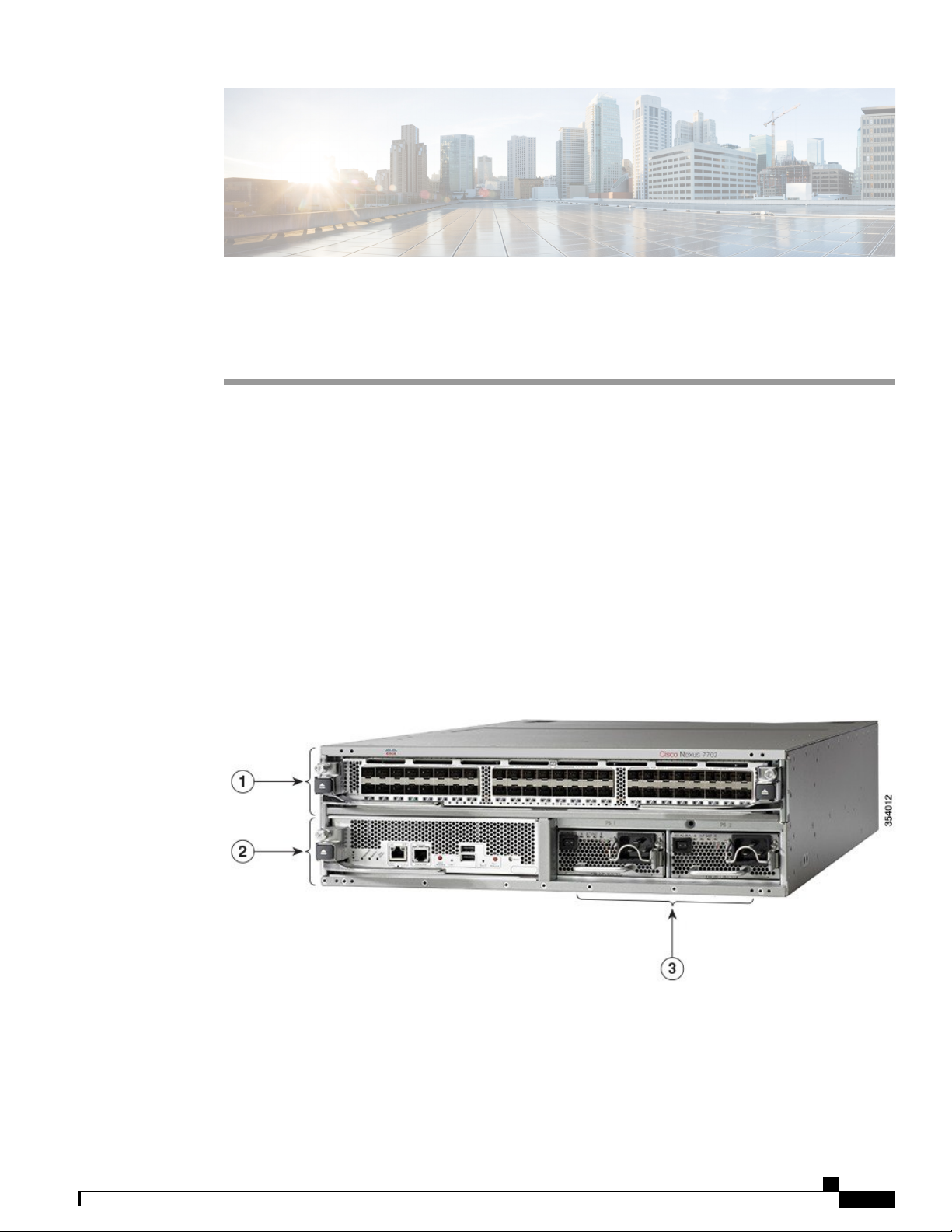
The Cisco Nexus 7702 chassis has two slots, one for the supervisor module and one for the I/O module. The
chassis has two power supply slots which support either AC or DC 3-kW and HVAC/HVDC 3.5-kW power
supplies. The chassis also has one fan tray at the rear. The following figure shows the standard hardware
features seen from the front of the chassis.
Figure 1: Standard Hardware Features on the Front of the Cisco Nexus 7702 Chassis
Cisco Nexus 7702 Hardware Installation Guide
1
Overview of the Cisco Nexus 7702 Switch Installation Features
Overview
1
I/O modules (one)
48-port 1- and 10-Gigabit Ethernet I/O module (N77-F348XP-23)
•
48-port 1- and 10-Gigabit Ethernet I/O module (N77-M348XP-23L)
•
24-port 40-Gigabit Ethernet I/O module (N77-F324FQ-25)
•
24-port 40-Gigabit Ethernet I/O module (N77-M324FQ-25L)
•
12-port 100-Gigabit Ethernet I/O module (N77-F312CK-26)
•
12-port 100-Gigabit Ethernet I/O module (N77-M312CQ-26L)
•
Supervisor modules (one) (N77-SUP2E)2
3
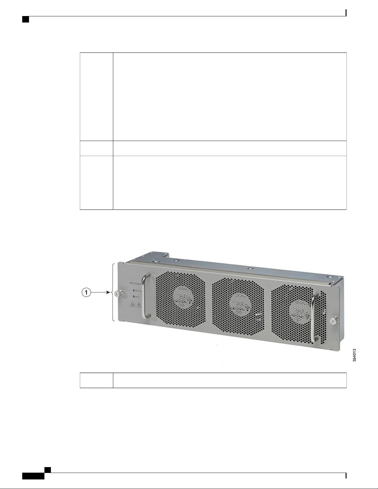
Figure 2: Standard Hardware Features on the Rear of the Cisco Nexus 7702 Chassis
Power supplies (up to 2)
3-kW AC power supply (N77-AC-3KW)
•
3-kW DC power supply (N77-DC-3KW)
•
3.5-kW HVAC/HVDC power supply (N77-HV-3.5KW)
•
One fan tray (N77-C7702-FAN)1
Cisco Nexus 7702 Hardware Installation Guide
2

CHAPTER 2
Preparing the Site
This chapter includes the following sections:
Humidity Requirements, page 3
•
Altitude Requirements, page 3
•
Dust and Particulate Requirements, page 4
•
Minimizing Electromagnetic and Radio Frequency Interference, page 4
•
Shock and Vibration Requirements, page 5
•
Grounding Requirements, page 5
•
Planning for Power Requirements, page 5
•
Rack and Cabinet Requirements, page 8
•
Clearance Requirements, page 10
•
Humidity Requirements
High humidity can cause moisture to seep into the switch. Moisture can cause corrosion of internal components
and degradation of properties such as electrical resistance, thermal conductivity, physical strength, and size.
The switch is rated to operate at 8 to 80 percent relative humidity, with a humidity gradation of 10 percent
per hour.
The switch can withstand from 5 to 90 percent relative humidity. Buildings in which the climate is controlled
by air-conditioning in the warmer months and by heat during the colder months usually maintain an acceptable
level of humidity for the switch equipment. However, if the switch is located in an unusually humid location,
you should use a dehumidifier to maintain the humidity within an acceptable range.
Altitude Requirements
If you operate a switch at a high altitude (low pressure), the efficiency of forced and convection cooling is
reduced and can result in electrical problems that are related to arcing and corona effects. This condition can
also cause sealed components with internal pressure, such as electrolytic capacitors, to fail or to perform at a
Cisco Nexus 7702 Hardware Installation Guide
3

Dust and Particulate Requirements
reduced efficiency. This switch is rated to operate at altitudes from –500 to 13,123 feet (–152 to 4,000 meters).
You can store the switch at altitudes of –1,000 to 30,000 feet (–305 to 9,144 meters).
Dust and Particulate Requirements
Exhaust fans cool power supplies and system fan trays cool switches by drawing in air and exhausting air out
through various openings in the chassis. However, fans also ingest dust and other particles, causing contaminant
buildup in the switch and increased internal chassis temperature. A clean operating environment can greatly
reduce the negative effects of dust and other particles, which act as insulators and interfere with the mechanical
components in the switch.
Preparing the Site
Note
If you are using this switch in a nonclean environment, you can order and install an optional air filter.
This air filter requires that you also order the optional front door for the chassis.
In addition to regular cleaning, follow these precautions to avoid contamination of your switch:
Do not permit smoking near the switch.
•
Do not permit food or drink near the switch.
•
Minimizing Electromagnetic and Radio Frequency Interference
Electromagnetic interference (EMI) and radio frequency interference (RFI) from the switch can adversely
affect other devices such as radio and television (TV) receivers operating near the switch. Radio frequencies
that emanate from the switch can also interfere with cordless and low-power telephones. Conversely, RFI
from high-power telephones can cause spurious characters to appear on the switch monitor.
RFI is defined as any EMI with a frequency above 10 kHz. This type of interference can travel from the switch
to other devices through the power cable and power source or through the air like transmitted radio waves.
The Federal Communications Commission (FCC) publishes specific regulations to limit the amount of EMI
and RFI that can be emitted by computing equipment. Each switch meets these FCC regulations.
To reduce the possibility of EMI and RFI, follow these guidelines:
Cover all open expansion slots with a metal filler.
•
Always use shielded cables with metal connector shells for attaching peripherals to the switch.
•
When wires are run for any significant distance in an electromagnetic field, interference can occur between
the field and the signals on the wires and cause the following implications:
Bad wiring can result in radio interference emanating from the plant wiring.
•
Strong EMI, especially when it is caused by lightning or radio transmitters, can destroy the signal drivers
•
and receivers in the chassis and even create an electrical hazard by conducting power surges through
lines into equipment.
Cisco Nexus 7702 Hardware Installation Guide
4
Preparing the Site
Shock and Vibration Requirements
Note
To predict and prevent strong EMI, you might need to consult experts in radio frequency interference
(RFI).
The wiring is unlikely to emit radio interference if you use twisted-pair cable with a good distribution of
grounding conductors. If you exceed the recommended distances, use a high-quality twisted-pair cable with
one ground conductor for each data signal when applicable.
If the wires exceed the recommended distances, or if wires pass between buildings, give special consideration
to the effect of a lightning strike in your vicinity. The electromagnetic pulse caused by lightning or other
high-energy phenomena can easily couple enough energy into unshielded conductors to destroy electronic
switches. You may want to consult experts in electrical surge suppression and shielding if you had similar
problems in the past.
Shock and Vibration Requirements
The switch has been shock- and vibration-tested for operating ranges, handling, and earthquake standards to
Network Equipment Building Standards (NEBS) Zone 4 per GR-63-Core.
Grounding Requirements
The switch is sensitive to variations in voltage supplied by the power sources. Overvoltage, undervoltage,
and transients (or spikes) can erase data from the memory or cause components to fail. To protect against
these types of problems, ensure that there is an earth-ground connection for the switch. You can connect the
grounding pad on the switch either directly to the earth-ground connection or to a fully bonded and grounded
rack.
You must provide the grounding cable to make this connection but you can connect the grounding wire to the
switch using a grounding lug that ships with the switch. Size the grounding wire to meet local and national
installation requirements. Depending on the power supply and system, a 12 AWG to 6 AWG copper conductor
is required for U.S. installations (for those installations, we recommend that you use commercially available
6 AWG wire). The length of the grounding wire depends on the proximity of the switch to proper grounding
facilities.
Note
You automatically ground the AC power supplies when you connect them to a power source, but you
cannot ground a 3-kW DC power supply. You must connect the chassis to the facility earth ground.
Planning for Power Requirements
To plan for the power requirements of a switch, you must determine each of the following:
Power requirements of the switch
•
Minimum number of power supplies required to power the switch and its components
•
Power mode to use and the number of additional power supplies required for that mode
•
Cisco Nexus 7702 Hardware Installation Guide
5
Planning for Power Requirements
You must also ensure that the circuit used for the switch is dedicated to the switch to minimize the possibility
of circuit failure.
When you know the amount of power that is required for operations (available power) and redundancy (reserve
power), you can plan for the required number of input power receptacles with reach of the switch location.
Preparing the Site
Step 1
Determine the power requirement for the switch by summing the maximum wattage for each installed module (see the
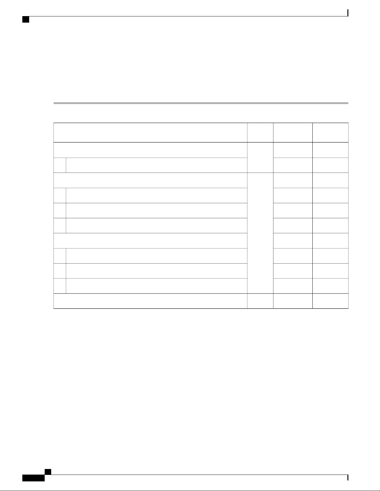
following table).
QuantityComponent
Maximum
Power
1Supervisor Modules
Typical
Power
——
137 W265 WSupervisor 2 Enhanced (N77-SUP2E)
1F3 I/O Modules
——
450 W480 W48-port 1- and 10-Gigabit Ethernet I/O module (N77-F348XP-23)
650 W740 W24-port 40-Gigabit Ethernet I/O module (N77-F324FQ-25)
640 W730 W12-port 100-Gigabit Ethernet I/O module (N77-F312CK-26)
M3 I/O Modules
——
500 W560 W48-port 1- and 10-Gigabit Ethernet I/O module (N77-M348XP-23L)
700 W750 W24-port 40-Gigabit Ethernet I/O module (N77-M324FQ-25L)
800 W1095 W12-port 100-Gigabit Ethernet I/O module (N77-M312CQ-26L)
Step 2
Step 3
6
50 W300 W1Fan Tray (N77-C7702-FAN)
Determine the number of power supplies needed for the available power requirement by dividing the power requirement
amount (see Step 1) by the output wattage of the power supplies installed in the switch.
Select one of the following power modes to determine the number of additional power supplies required for reserve
power:
• Combined power—Do not add any power supplies to the number of power supplies calculated for the available
power in Step 2. This power mode does not provide power redundancy, so no extra power supplies are needed.
• Power supply redundancy (n+1 redundancy)—Add one power supply (reserve power supply). This form of power
redundancy provides a reserve power supply that can replace any active power supply that goes offline.
• Input source redundancy (grid redundancy)—Add enough power supplies (reserve power supplies) to at least equal
the total output of the active power supplies (number of power supplies calculated in Step 2). Typically, you would
double the number of power supplies. You must plan for a second power source for the reserve power supplies.
Cisco Nexus 7702 Hardware Installation Guide
Preparing the Site
Planning for Power Requirements
• Full redundancy (n+1 and grid redundancy)—Add enough power supplies (reserve power supplies) to at least equal
the output of the active power supplies (number of power supplies calculated in Step 2). For power supply (n+1)
redundancy, ensure that . For input-source (grid) redundancy, you will probably double the number of power
supplies. You must plan for a second power source with at least the same amount of input power for the reserve
power supplies. Either one of the reserve power supplies can replace any of the active power supplies.
Step 4
Be sure that the power source circuits are dedicated to the switch and not to other electrical equipment.
For combined power mode (no power redundancy) or power supply (n+1) redundancy, you need only one dedicated
circuit. The requirements for each circuit are listed in the following table.
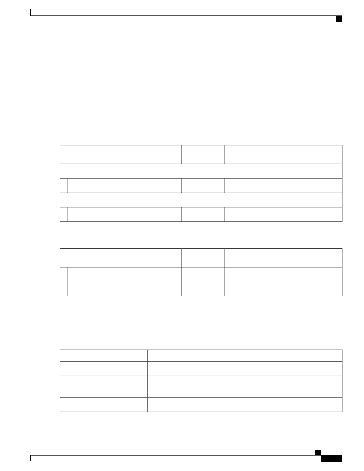
Table 1: Circuit Requirements for 3-kW Power Supplies
Power Supply
Requirement for Each CircuitNumber of
Circuits
AC Power Supplies
20 A at 110 VAC or 220 VAC1(N77-AC-3.0KW)3-kW power supply
DC Power Supplies
20A1(N77-DC-3.0KW)3-kW power supply
Table 2: Circuit Requirements for 3.5-kW HVAC/HVDC Power Supplies
Power Supply
Requirement for Each CircuitNumber of
Circuits
1(N77-HV-3.5KW)3.5-kW
HVAC/HVDC power
supply
20 A at 110 VAC, 210 VAC, 220/230 VAC and
277 VAC or 20 A at 210 VDC, 220/240 VDC
and 380 VDC
Step 5
Plan the placement of the input power receptacles within reach of the power cables used for each power supply (see the
following table for the maximum distances).
Typically, power receptacles are placed on the rack with the switch. If the DC power source is further than allowed by
the DC power cables, you can install a power interface unit (PIU) in the rack with the switch and connect that to the
power source with other cabling.
Maximum Distance Between Receptacle and Power SupplyPower Supply
12 feet (3.6 m)All AC power supplies
14 feet (4.26 m)HVAC/HVDC 3.5-kW power
supplies
Determined by the length of the power cord that you supply.DC 3-kW power supplies
Cisco Nexus 7702 Hardware Installation Guide
7
Rack and Cabinet Requirements
Rack and Cabinet Requirements
You can install the following types of racks or cabinets for your switch:
Standard perforated cabinets
•
Solid-walled cabinets with a roof fan tray (bottom to top cooling)
•
Preparing the Site
Note
Standard open four-post Telco racks
•
Standard open two-post Telco racks
•
To correctly install the switch in a cabinet that is located in a hot-aisle/cold-aisle environment, you should fit
the cabinet with baffles to prevent exhaust air from recirculating into the chassis air intake.
Work with your cabinet vendors to determine which of their cabinets meet the following requirements or see
the Cisco Technical Assistance Center (TAC) for recommendations:
Use a standard 19-inch, four-post Electronic Industries Alliance (EIA) cabinet or rack with mounting
•
rails that conform to English universal hole spacing per section 1 of the ANSI/EIA-310-D-1992 standard.
The height of the rack or cabinet must accommodate the 3-RU (5.25 inches or 13.3 cm) height of the
•
switch.
The depth of a four-post rack must be 24 to 32 inches (61.0 to 81.3 cm) between the front and rear
•
mounting brackets.
Required clearances between the chassis and the edges of its rack or the interior of its cabinet are as
•
follows:
Installation clearance requirements for solid-wall cabinets are not in the scope of this
guide. Such installations have to be custom-engineered by a cooling professional. The
customised configuration should satisfy the requirements mentioned in the Preparing
the Site and the Switch Specifications sections.
7.5 inches (19.1 cm) between the front of the chassis and the front of the rack or interior of the
◦
cabinet (required for cabling).
3.0 inches (7.6 cm) between the rear of the chassis and the perforated rear door of the cabinet
◦
(required for airflow in the cabinet if used).
Note
No clearance is required between the chassis and the sides of the rack or cabinet (no side airflow).
◦
Additionally, you must consider the following site requirements for the rack:
Cisco Nexus 7702 Hardware Installation Guide
8
This requirement does not apply to enclosures which have a solid rear door or wall with
other exhaust configurations.

Preparing the Site
Rack and Cabinet Requirements
Power receptacles must be located within reach of the power cords used with the switch.
•
AC power supplies
◦
Power cords for 3-kW AC power supplies are 8 to 12 feet (2.5 to 3.6 m) long.
◦
DC power supplies
◦
Power cords for 3.0-kW DC power supplies are supplied and dimensioned by the customer.
◦
HVAC/HVDC power supplies
◦
Power cords for 3.5-kW HVAC/HVDC power supplies are 14 feet (4.26 m) long.
◦
Clearance required for cables that connect to as many as 200 ports (in addition to the cabling required
•
for other devices in the same rack). These cables must not block access to any removable chassis modules
or block airflow into or out of the chassis. Route the cables through the cable management frames on
the left and right sides of the chassis.
Where necessary, have a seismic rating of Network Equipment Building Standards (NEBS) Zone 3 or
•
Zone 4, per GR-63-CORE if required.
Minimum gross load rating of 2000 lb (907.2 kg) (static load rating) if supporting two switches.
•
Cisco Nexus 7702 Hardware Installation Guide
9
Clearance Requirements
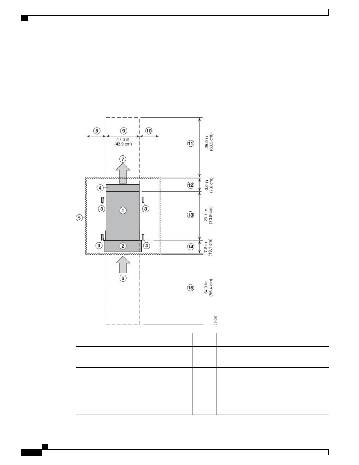
Clearance Requirements
You must provide the chassis with adequate clearance between the chassis and any other rack, device, or
structure so that you can properly install the chassis, route cables, provide airflow, and maintain the switch.
For the clearances required for an installation of this chassis, see the following figure.
Figure 3: Clearances Required Around the Chassis
Preparing the Site
Chassis width9Chassis1
10Cable management frames2
11Vertical rack-mount posts and rails3
4
of the chassis (allow 2 inches [5 cm])
Cisco Nexus 7702 Hardware Installation Guide
10
12Area used for fan tray handles at the rear
No right side clearance required (no airflow on
right side)
Rear service clearance required to replace fan
trays and fabric modules
Airflow clearance area required at the rear of
the chassis within the cabinet (if a cabinet is
used)
Preparing the Site
Clearance Requirements
Note
5
Chassis depth13Nearest object or inside of cabinet (no
side clearance required)
6
14Air intake from the cold aisle for all
modules and power supplies
Clearance required between the front of the
chassis and the inside of the cabinet (if used) or
the edge of the cold aisle (if no cabinet) for the
cable management frames and the optional front
doors
7
15Air exhaust to the hot aisle for all
modules and power supplies
Front service clearance required for installing
the chassis and replacing the modules on the
front of the chassis
8
No left side clearance required (no
airflow on left side)
Figure 3: Clearances Required Around the Chassis, on page 10 shows the clearance requirements for
conventional cold-aisle to hot-aisle systems which include rack enclosures with perforated front and rear
doors. The information given above does not apply to enclosures which have a solid rear or front door or
wall with other inlet or exhaust configurations. We recommend consulting a cooling professional if a solid
rear or front door is used.
Cisco Nexus 7702 Hardware Installation Guide
11

Clearance Requirements
Preparing the Site
Cisco Nexus 7702 Hardware Installation Guide
12

Installing the Switch Chassis
This chapter includes the following topics:
Installing a Rack or Cabinet, page 13
•
Unpacking and Inspecting a New Switch, page 14
•
Installing the Chassis in a Two-Post Rack, page 15
•
Installing the Chassis on a Four-Post Rack or Cabinet, page 19
•
Grounding a Switch Chassis, page 23
•
Installing Cable Management Frames onto the Chassis , page 24
•
Attaching the Front Door to the Chassis, page 26
•
Installing a Rack or Cabinet
CHAPTER 3
Step 1
Step 2
Step 3
Before you install the switch, you must install a standard four-post, 19-inch EIA data center rack (or a cabinet
that contains such a rack) Rack and Cabinet Requirements.
Bolt the rack to the concrete subfloor before moving the chassis onto it.
Warning
If the rack has bonded construction, connect it to the earth ground. This action enables you to easily ground the switch
and its components and to ground your electrostatic discharge (ESD) wrist strap to prevent damaging discharges when
you handle ungrounded components before installing them.
If you need access to the source power at the rack, include either AC power receptacles or a DC power interface unit
(PIU) with the amperage required by the switch that you are installing. .
If you are using DC power, be sure that the DC power supply is grounded and that there is direct access to the facility
DC power or indirect access though a power interface unit (PIU). You must connect the DC power supply to the earth
ground before you connect it to the facility DC power.
Stability hazard. The rack stabilizing mechanism must be in place, or the rack must be bolted to the floor
before you slide the unit out for servicing. Failure to stabilize the rack can cause the rack to tip over.
Take care when connecting units to the supply circuit so that wiring is not overloaded.Warning
Cisco Nexus 7702 Hardware Installation Guide
13
Unpacking and Inspecting a New Switch
Installing the Switch Chassis
Note
If you are using the combined power mode or power-supply redundancy, you need only one power source. If
you are using input-source redundancy or full redundancy, you need two power sources.
Unpacking and Inspecting a New Switch
Before you install a new chassis, you need to unpack and inspect it to be sure that you have all the items that
you ordered and verify that the switch was not damaged during shipment. If anything is damaged or missing,
contact your customer representative immediately.
Caution
When you handle the chassis or its components, you must follow ESD protocol at all times to prevent
ESD damage. This protocol includes but is not limited to wearing an ESD wrist strap that you connect to
the earth ground.
Do not discard the shipping container when you unpack the switch. Flatten the shipping cartons and store
Tip
them with the pallet used for the system. If you need to move or ship the system in the future, you will
need these containers.
Step 1
Compare the shipment to the equipment list that is provided by your customer service representative and verify that you
have received all of the ordered items.
The shipment should include boxes for the following:
System chassis, which includes the following installed components:
•
1 supervisor module
◦
1 I/0 module
◦
1 fan tray
◦
1 to 2 power supply units
◦
Switch accessory kit
•
To see a list of what is included in this kit, see Cisco Nexus 7702 Switch Accessory Kit, on page 127.
Cable management frames
•
Left and right side frames
◦
Top and bottom hood frames
◦
M4x14 mm flat-head Phillips screws (4)
◦
• Front door kit — Optional
Front door (1) (69-100222-01)
◦
Cisco Nexus 7702 Hardware Installation Guide
14
Installing the Switch Chassis
• Air filter kit — Optional
Air filter (1) for the front door
◦
Cable-management frame brush filters (2)
◦
M3 x 12 mm flat-head Phillips screws (4)
◦
• Center-mount kit — For Two-Post rack installation
Installing the Chassis in a Two-Post Rack
Step 2
Step 3
Check the contents of each box for damage.
If you notice any discrepancies or damage, send the following information to your customer service representative by
email:
Invoice number of the shipper (see the packing slip)
•
Model and serial number of the missing or damaged unit
•
Description of the problem and how it affects the installation
•
Installing the Chassis in a Two-Post Rack
Before You Begin
Verify that the chassis shipment is complete and undamaged.
•
Verify that a two-post rack is installed and secured to the subfloor.
•
•
Warning
Stability hazard. The rack stabilizing mechanism must be in place, or the rack must be
bolted to the floor before you slide the unit out for servicing. Failure to stabilize the
rack can cause the rack to tip over.
Note
If there are other devices in the rack, verify that the devices that are heavier than this chassis are installed
•
below where you are going to install the chassis and lighter devices are installed above where you are
going to install the chassis.
Verify that the data center ground is accessible where you are installing the chassis.
•
Fully loaded, the chassis can weigh up to 81.7 lb (37.05 kg). You can lighten the chassis for easier moving
by removing a power supply. To determine the full weight of the chassis and the appropriate weight rating
for the mechanical lift, see Weights and Quantities for the Chassis, Modules, Fan Trays, and Power
Supplies, on page 79.
Cisco Nexus 7702 Hardware Installation Guide
15

Installing the Chassis in a Two-Post Rack
Installing the Switch Chassis
Step 1
Warning
To prevent bodily injury when mounting or servicing this unit in a rack, you must take special precautions
to ensure that the system remains stable. The following guidelines are provided to ensure your safety:
This unit should be mounted at the bottom of the rack if it is the only unit in the rack.
•
When mounting this unit in a partially filled rack, load the rack from the bottom to the top with the
•
heaviest component at the bottom of the rack.
If the rack is provided with stabilizing devices, install the stabilizers before mounting or servicing
•
the unit in the rack.
If you need to make the chassis as light as possible for moving, you can optionally remove the fan tray and power supplies.
To remove a power supply, follow these steps:
•
Push and hold the release handle on the power supply to the left.
1
Pull the power supply about two inches (about 5 cm) out of the chassis.
2
Place one hand under the power supply to support its weight and pull the power supply out of the chassis.
3
Place the power supply on an antistatic surface.
4
To remove a fan tray, follow these steps:
•
Step 2
Unscrew the two captive screws on the front of the fan tray.
1
Hold both handles on the fan tray with both of your hands and pull the fan tray out of the chassis.
2
Place the fan tray on an antistatic surface.
3
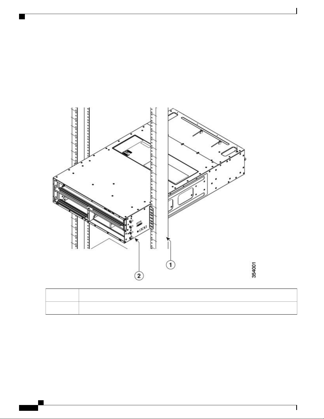
Align the rear of the chassis to the front of the rack or cabinet.
Cisco Nexus 7702 Hardware Installation Guide
16
Installing the Switch Chassis
Installing the Chassis in a Two-Post Rack
Step 3
Push the chassis halfway onto the rack or cabinet.
Figure 4: Moving a Chassis onto a Rack or Cabinet
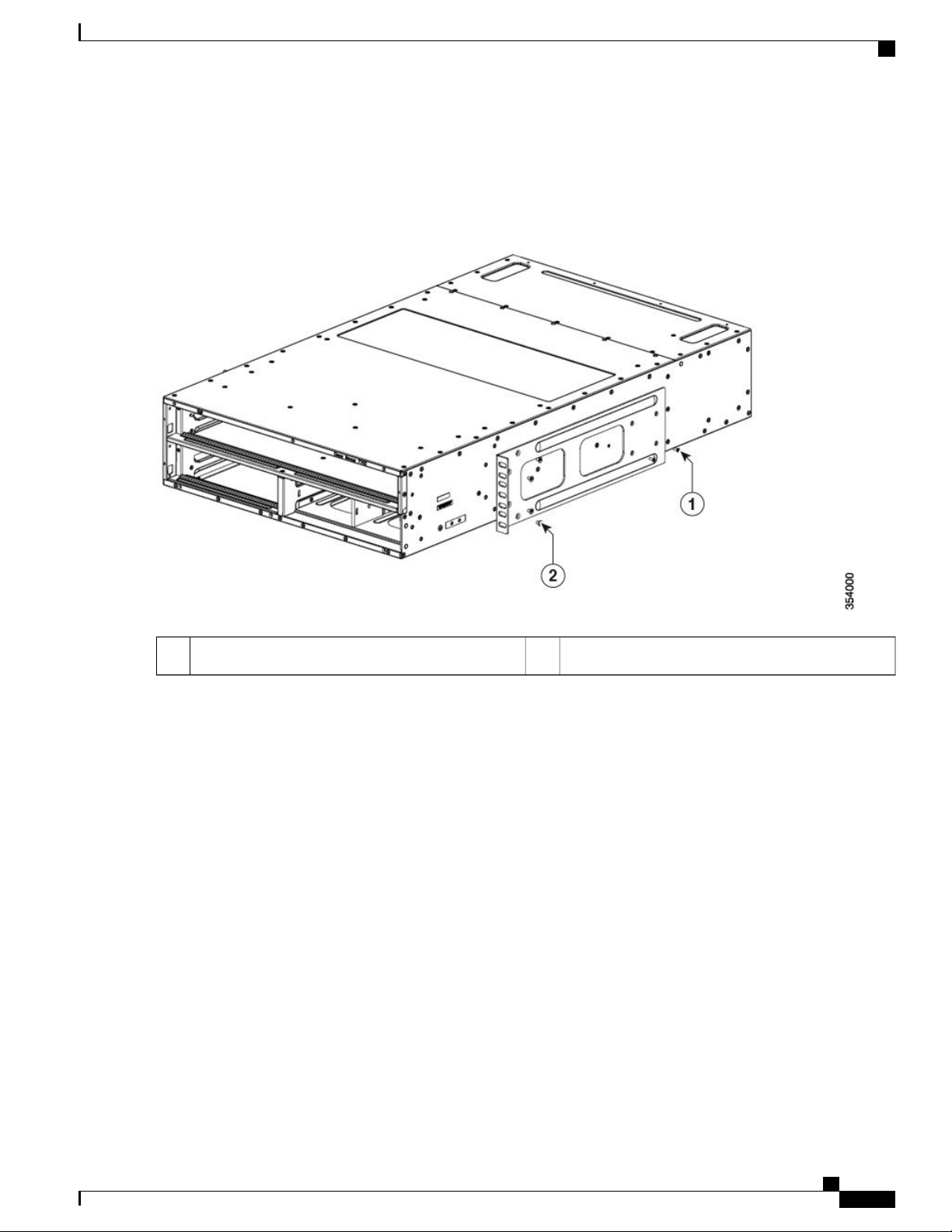
Total of eight M4 screws (for brackets on both sides).2Total of four M3 screws (for brackets on both sides).1
Cisco Nexus 7702 Hardware Installation Guide
17
Installing the Chassis in a Two-Post Rack
Installing the Switch Chassis
Step 4
Step 5
Push the chassis all the way onto the rack so that the vertical mounting brackets on the chassis come in contact with the
vertical mounting rails on the rack.
Use 2 center mount-brackets with eight M4 screws and two M3 screws to attach each of the two vertical mounting
brackets on the chassis to the two vertical mounting rails on the rack. It is recommended to use a minimum of 8 screws
(user preference from the accessory kit) on the front of the chassis to secure the chassis to the 2-post rack.
Figure 5: Attaching the Chassis to the Rack
Step 6
18
Vertical mounting rails on the rack1
Install a total of eight screws (user preference from the accessory kit) at the front to secure the chassis.2
If you removed the fan tray before moving the chassis, reinstall each one in the chassis as follows:
a) Holding each of the two handles on the fan tray with your two hands, align the fan tray to an open fan tray slot.
b) Slide the fan tray into the slot until the front of the fan tray comes in contact with the rear of the chassis.
Note
The two alignment pins on the fan tray (on the left and the right) should go into holes in the chassis and the
two captive screws on the fan tray should align to screw holes in the chassis.
Cisco Nexus 7702 Hardware Installation Guide

Installing the Switch Chassis
c) Screw in the two captive screws to the chassis and tighten each screw to 8 in-lb (0.9 N·m).
Installing the Chassis on a Four-Post Rack or Cabinet
Step 7
If you removed any power supplies before moving the chassis, reinstall each one as follows:
a) Determine which power supply slots to fill and ensure that each of those slots is open.
If you are using the combined or power supply redundancy mode, you can use any slot for the power supply that you
are installing. If you are using the input-source or full redundancy mode, you must group the power supplies that are
to be connected to the same grid on either the left or right power supply slots in the chassis.
b) Place one hand on the front of the power supply and place your other hand under it to support its weight.
c) Align the power supply to an open power supply slot.
Note
d) Slide the power supply all the way into the slot until its release handle clicks and the module stops.
The alignment bracket on top of the power supply should align to a track at the top of the slot and a bar at
the bottom of the power supply should be guided by a track at the bottom of the slot.
Installing the Chassis on a Four-Post Rack or Cabinet
Before You Begin
Verify that the chassis shipment is complete and undamaged.
•
Verify that a rack or cabinet is installed and secured to the subfloor.
•
Note
Warning
Verify that there is 3 RU (5.25 inches [13.3 cm]) of space above the rails to install the chassis.
•
If there are other devices in the rack, verify that the devices that are heavier than this chassis are installed
•
below where you are going to install the chassis and lighter devices are installed above where you are
going to install the chassis.
Verify that the data center ground is accessible where you are installing the chassis.
•
Fully loaded, the chassis can weigh up to 81.7 lb (37.05 kg). You can lighten the chassis for easier moving
by removing a power supply. To determine the full weight of the chassis and the appropriate weight rating
for the mechanical lift, see Weights and Quantities for the Chassis, Modules, Fan Trays, and Power
Supplies, on page 79.
Stability hazard. The rack stabilizing mechanism must be in place, or the rack must be
bolted to the floor before you slide the unit out for servicing. Failure to stabilize the
rack can cause the rack to tip over.
Cisco Nexus 7702 Hardware Installation Guide
19

Installing the Chassis on a Four-Post Rack or Cabinet
Installing the Switch Chassis
Step 1
Warning
To prevent bodily injury when mounting or servicing this unit in a rack, you must take special precautions
to ensure that the system remains stable. The following guidelines are provided to ensure your safety:
This unit should be mounted at the bottom of the rack if it is the only unit in the rack.
•
When mounting this unit in a partially filled rack, load the rack from the bottom to the top with the
•
heaviest component at the bottom of the rack.
If the rack is provided with stabilizing devices, install the stabilizers before mounting or servicing
•
the unit in the rack.
If you need to make the chassis as light as possible for moving, you can optionally remove the fan tray and power supplies.
To remove a power supply, follow these steps:
•
Slide the handle in the middle of the ejector lever towards the end of the lever and rotate the lever away from
1
the power supply.
Pull the power supply a couple of inches (about 5 cm) out of the chassis.
2
Place one hand under the power supply to support its weight and pull the power supply out of the chassis.
3
Place the power supply on an antistatic surface.
4
To remove a fan tray, follow these steps:
•
Unscrew the two captive screws on the front of the fan tray.
1
Hold both handles on the fan tray with both of your hands and pull the fan tray out of the chassis.
2
Place the fan tray on an antistatic surface.
3
Cisco Nexus 7702 Hardware Installation Guide
20
 Loading...