

Cisco Nexus 7004, Nexus 7010, Nexus 7009, Nexus 7018 Hardware Installation And Reference Manual
Page 1

Cisco Nexus 7000 Series Hardware
Installation and Reference Guide
For the Cisco Nexus 7004, 7009, 7010, and 7018 Switches
Last updated: April 2014
Americas Headquarters
Cisco Systems, Inc.
170 West Tasman Drive
San Jose, CA 95134-1706
USA
http://www.cisco.com
Tel: 408 526-4000
800 553-NETS (6387)
Fax: 408 527-0883
Page 2

THE SPECIFICATIONS AND INFORMATION REGARDING THE PRODUCTS IN THIS MANUAL ARE SUBJECT TO CHANGE WITHOUT NOTICE. ALL
STATEMENTS, INFORMATION, AND RECOMMENDATIONS IN THIS MANUAL ARE BELIEVED TO BE ACCURATE BUT ARE PRESENTED WITHOUT
WARRANTY OF ANY KIND, EXPRESS OR IMPLIED. USERS MUST TAKE FULL RESPONSIBILITY FOR THEIR APPLICATION OF ANY PRODUCTS.
THE SOFTWARE LICENSE AND LIMITED WARRANTY FOR THE ACCOMPANYING PRODUCT ARE SET FORTH IN THE INFORMATION PACKET THAT
SHIPPED WITH THE PRODUCT AND ARE INCORPORATED HEREIN BY THIS REFERENCE. IF YOU ARE UNABLE TO LOCATE THE SOFTWARE LICENSE
OR LIMITED WARRANTY, CONTACT YOUR CISCO REPRESENTATIVE FOR A COPY.
The following information is for FCC compliance of Class A devices: This equipment has been tested and found to comply with the limits for a Class A digital device, pursuant
to part 15 of the FCC rules. These limits are designed to provide reasonable protection against harmful interference when the equipment is operated in a commercial
environment. This equipment generates, uses, and can radiate radio-frequency energy and, if not installed and used in accordance with the instruction manual, may cause
harmful interference to radio communications. Operation of this equipment in a residential area is likely to cause harmful interference, in which case users will be required
to correct the interference at their own expense.
The following information is for FCC compliance of Class B devices: The equipment described in this manual generates and may radiate radio-frequency energy. If it is not
installed in accordance with Cisco’s installation instructions, it may cause interference with radio and television reception. This equipment has been tested and found to
comply with the limits for a Class B digital device in accordance with the specifications in part 15 of the FCC rules. These specifications are designed to provide reasonable
protection against such interference in a residential installation. However, there is no guarantee that interference will not occur in a particular installation.
Modifying the equipment without Cisco’s written authorization may result in the equipment no longer complying with FCC requirements for Class A or Class B digital
devices. In that event, your right to use the equipment may be limited by FCC regulations, and you may be required to correct any interference to radio or television
communications at your own expense.
You can determine whether your equipment is causing interference by turning it off. If the interference stops, it was probably caused by the Cisco equipment or one of its
peripheral devices. If the equipment causes interference to radio or television reception, try to correct the interference by using one or more of the following measures:
• Turn the television or radio antenna until the interference stops.
• Move the equipment to one side or the other of the television or radio.
• Move the equipment farther away from the television or radio.
• Plug the equipment into an outlet that is on a different circuit from the television or radio. (That is, make certain the equipment and the television or radio are on circuits
controlled by different circuit breakers or fuses.)
Modifications to this product not authorized by Cisco Systems, Inc. could void the FCC approval and negate your authority to operate the product.
The Cisco implementation of TCP header compression is an adaptation of a program developed by the University of California, Berkeley (UCB) as part of UCB’s public
domain version of the UNIX operating system. All rights reserved. Copyright © 1981, Regents of the University of California.
NOTWITHSTANDING ANY OTHER WARRANTY HEREIN, ALL DOCUMENT FILES AND SOFTWARE OF THESE SUPPLIERS ARE PROVIDED “AS IS” WITH
ALL FAULTS. CISCO AND THE ABOVE-NAMED SUPPLIERS DISCLAIM ALL WARRANTIES, EXPRESSED OR IMPLIED, INCLUDING, WITHOUT
LIMITATION, THOSE OF MERCHANTABILITY, FITNESS FOR A PARTICULAR PURPOSE AND NONINFRINGEMENT OR ARISING FROM A COURSE OF
DEALING, USAGE, OR TRADE PRACTICE.
IN NO EVENT SHALL CISCO OR ITS SUPPLIERS BE LIABLE FOR ANY INDIRECT, SPECIAL, CONSEQUENTIAL, OR INCIDENTAL DAMAGES, INCLUDING,
WITHOUT LIMITATION, LOST PROFITS OR LOSS OR DAMAGE TO DATA ARISING OUT OF THE USE OR INABILITY TO USE THIS MANUAL, EVEN IF CISCO
OR ITS SUPPLIERS HAVE BEEN ADVISED OF THE POSSIBILITY OF SUCH DAMAGES.
Cisco and the Cisco logo are trademarks or registered trademarks of Cisco and/or its affiliates in the U.S. and other countries. To view a list of Cisco trademarks, go to this
URL: www.cisco.com/go/trademarks. Third-party trademarks mentioned are the property of their respective owners. The use of the word partner does not imply a partnership
relationship between Cisco and any other company. (1110R)
Any Internet Protocol (IP) addresses used in this document are not intended to be actual addresses. Any examples, command display output, and figures included in the
document are shown for illustrative purposes only. Any use of actual IP addresses in illustrative content is unintentional and coincidental.
Cisco Nexus 7000 Series Hardware Installation and Reference Guide
© 2008-2014 Cisco Systems, Inc. All rights reserved..
Page 3
New and Changed Information
This chapter provides release-specific information for each new and changed feature in the Cisco Nexus
7000 Series Hardware Installation and Reference Guide. The latest version of this document is available
at the following Cisco website:
http://www.cisco.com/en/US/docs/switches/datacenter/hw/nexus7000/installation/guide/n7k_hig_book.
html
Tabl e 1 summarizes the new and changed features for the Cisco Nexus 7000 Series Hardware
Installation and Reference Guide, and tells you where they are documented.
Table 1 New and Changed Features for Release 6.2(8)
Feature Description
Supported optics and
cables
EPLD images Updated EPLD images for the NAM and
10-Mbps support for
Cisco Nexus 2248TP-E
FEX
Additional optics and cables supported by the
12-port 40-Gigabit Ethernet I/O module
(N7K-F312FQ-25) and 6-port 40-Gigabit
Ethernet I/O module (N7K-M206FQ-23)
various I/O modules
Support for 10-Mbps speed for the Cisco
Nexus 2248TP-E FEX
Changed in
Release Where Documented
6.2(8) Chapter 7, “Connecting the Cisco
Nexus 7000 Series Switch to the
Network”
6.2(8) Chapter 8, “Managing the Switch
Hardware”
6.2(8) Appendix B, “Transceivers and
Module Connectors”
OL-23069-7
Cisco Nexus 7000 Series Hardware Installation and Reference Guide
iii
Page 4

New and Changed Information
iv
Cisco Nexus 7000 Series Hardware Installation and Reference Guide
OL-23069-7
Page 5

Audience
Preface
This preface describes the audience, organization, and conventions of the Cisco Nexus 7000 Series
Hardware Installation and Reference Guide. It also provides information on how to obtain related
documentation.
This preface includes the following sections:
• Audience, page v
• Organization, page v
• Document Conventions, page vi
• Related Documentation, page xii
• Obtaining Documentation and Submitting a Service Request, page xiii
This guide is for experienced network system administrators who configure and maintain Cisco Nexus
7004, 7009, 7010, and 7018 switches.
Organization
This document describes how to install the Cisco Nexus 7004, 7009, 7010, and 7018 switches. For
information about installing the Cisco Nexus 7706, 7710, or 7718 switches, see the individual hardware
installation guide for each product.
This document is organized as follows:
Chapter Description
Chapter 1, “Overview” Provides an overview of the installation
Chapter 2, “Installing a Cisco Nexus 7004 Chassis” Describes how to install the Cisco Nexus 7004
Chapter 3, “Installing a Cisco Nexus 7009 Chassis” Describes how to install the Cisco Nexus 7009
OL-23069-07
process.
hardware components.
hardware components.
Cisco Nexus 7000 Series Hardware Installation and Reference Guide
-v
Page 6
Chapter Description
Chapter 4, “Installing a Cisco Nexus 7010 Chassis” Describes how to install the Cisco Nexus 7010
hardware components.
Chapter 5, “Installing a Cisco Nexus 7018 Chassis” Describes how to install the Cisco Nexus 7018
hardware components.
Chapter 6, “Installing Power Supplies” Describes how to install the power supply units
in the Cisco Nexus 7000 Series switches.
Chapter 7, “Connecting the Cisco Nexus 7000 Series
Switch to the Network”
Chapter 8, “Managing the Switch Hardware” Describes how to manage the hardware for the
Chapter 9, “Troubleshooting” Describes how to troubleshoot the Cisco Nexus
Chapter 10, “Installing or Replacing Components” Describes how to replace Cisco Nexus 7000
Appendix A, “Technical Specifications” Provides system and site requirements that you
Appendix B, “Transceivers and Module Connectors” Provides the specifications for the connection
Appendix D, “Chassis and Module LEDs” Describes the switch and module LEDs that
Appendix E, “Repacking the Cisco Nexus 7000
Series Switch for Shipment”
Appendix F, “Site Preparation and Maintenance
Records”
Describes how to connect a Cisco Nexus 7000
Series switch to AC power and the network.
Cisco Nexus 7000 Series switch.
7000 Series hardware.
Series components during system operations.
should use for planning the installation of the
Cisco Nexus 7000 Series switch.
devices used to connect the Cisco Nexus 7000
Series switch to the Internet.
indicate system conditions.
Explains how you should repack the Cisco
Nexus 7000 Series switch in case you need to
ship it.
Provides contact information and a table for
recording site records.
Document Conventions
Command descriptions use these conventions:
Convention Description
boldface font Commands and keywords are in boldface.
italic font Arguments for which you supply values are in italics.
[ ] Elements in square brackets are optional.
[ x | y | z ] Optional alternative keywords are grouped in brackets and separated by vertical
string A nonquoted set of characters. Do not use quotation marks around the string or
Cisco Nexus 7000 Series Hardware Installation and Reference Guide
-vi
bars.
the string will include the quotation marks.
OL-23069-07
Page 7
Screen examples use these conventions:
screen font
boldface screen
font
italic screen font
Terminal sessions and information that the switch displays are in screen font.
Information you must enter is in boldface screen font.
Arguments for which you supply values are in italic screen font.
< > Nonprinting characters, such as passwords, are in angle brackets.
[ ] Default responses to system prompts are in square brackets.
!, # An exclamation point (!) or a pound sign (#) at the beginning of a line of code
indicates a comment line.
This document uses the following conventions:
Note Means reader take note. Notes contain helpful suggestions or references to material not covered in the
publication.
Caution Means reader be careful. In this situation, you might do something that could result in equipment
damage or loss of data.
Warning
Waarschuwing
IMPORTANT SAFETY INSTRUCTIONS
This warning symbol means danger. You are in a situation that could cause bodily injury. Before you
work on any equipment, be aware of the hazards involved with electrical circuitry and be familiar
with standard practices for preventing accidents. Use the statement number provided at the end of
each warning to locate its translation in the translated safety warnings that accompanied this
device.
SAVE THESE INSTRUCTIONS
BELANGRIJKE VEILIGHEIDSINSTRUCTIES
Dit waarschuwingssymbool betekent gevaar. U verkeert in een situatie die lichamelijk letsel kan
veroorzaken. Voordat u aan enige apparatuur gaat werken, dient u zich bewust te zijn van de bij
elektrische schakelingen betrokken risico's en dient u op de hoogte te zijn van de standaard
praktijken om ongelukken te voorkomen. Gebruik het nummer van de verklaring onderaan de
waarschuwing als u een vertaling van de waarschuwing die bij het apparaat wordt geleverd, wilt
raadplegen.
BEWAAR DEZE INSTRUCTIES
OL-23069-07
Cisco Nexus 7000 Series Hardware Installation and Reference Guide
-vii
Page 8

Varoitus
Attention
Warnung
TÄRKEITÄ TURVALLISUUSOHJEITA
Tämä varoitusmerkki merkitsee vaaraa. Tilanne voi aiheuttaa ruumiillisia vammoja. Ennen kuin
käsittelet laitteistoa, huomioi sähköpiirien käsittelemiseen liittyvät riskit ja tutustu
onnettomuuksien yleisiin ehkäisytapoihin. Turvallisuusvaroitusten käännökset löytyvät laitteen
mukana toimitettujen käännettyjen turvallisuusvaroitusten joukosta varoitusten lopussa näkyvien
lausuntonumeroiden avulla.
SÄILYTÄ NÄMÄ OHJEET
IMPORTANTES INFORMATIONS DE SÉCURITÉ
Ce symbole d'avertissement indique un danger. Vous vous trouvez dans une situation pouvant
entraîner des blessures ou des dommages corporels. Avant de travailler sur un équipement, soyez
conscient des dangers liés aux circuits électriques et familiarisez-vous avec les procédures
couramment utilisées pour éviter les accidents. Pour prendre connaissance des traductions des
avertissements figurant dans les consignes de sécurité traduites qui accompagnent cet appareil,
référez-vous au numéro de l'instruction situé à la fin de chaque avertissement.
CONSERVEZ CES INFORMATIONS
WICHTIGE SICHERHEITSHINWEISE
Dieses Warnsymbol bedeutet Gefahr. Sie befinden sich in einer Situation, die zu Verletzungen führen
kann. Machen Sie sich vor der Arbeit mit Geräten mit den Gefahren elektrischer Schaltungen und
den üblichen Verfahren zur Vorbeugung vor Unfällen vertraut. Suchen Sie mit der am Ende jeder
Warnung angegebenen Anweisungsnummer nach der jeweiligen Übersetzung in den übersetzten
Sicherheitshinweisen, die zusammen mit diesem Gerät ausgeliefert wurden.
Avvertenza
Advarsel
BEWAHREN SIE DIESE HINWEISE GUT AUF.
IMPORTANTI ISTRUZIONI SULLA SICUREZZA
Questo simbolo di avvertenza indica un pericolo. La situazione potrebbe causare infortuni alle
persone. Prima di intervenire su qualsiasi apparecchiatura, occorre essere al corrente dei pericoli
relativi ai circuiti elettrici e conoscere le procedure standard per la prevenzione di incidenti.
Utilizzare il numero di istruzione presente alla fine di ciascuna avvertenza per individuare le
traduzioni delle avvertenze riportate in questo documento.
CONSERVARE QUESTE ISTRUZIONI
VIKTIGE SIKKERHETSINSTRUKSJONER
Dette advarselssymbolet betyr fare. Du er i en situasjon som kan føre til skade på person. Før du
begynner å arbeide med noe av utstyret, må du være oppmerksom på farene forbundet med
elektriske kretser, og kjenne til standardprosedyrer for å forhindre ulykker. Bruk nummeret i slutten
av hver advarsel for å finne oversettelsen i de oversatte sikkerhetsadvarslene som fulgte med denne
enheten.
TA VARE PÅ DISSE INSTRUKSJONENE
-viii
Cisco Nexus 7000 Series Hardware Installation and Reference Guide
OL-23069-07
Page 9
Aviso
¡Advertencia!
Varning!
INSTRUÇÕES IMPORTANTES DE SEGURANÇA
Este símbolo de aviso significa perigo. Você está em uma situação que poderá ser causadora de
lesões corporais. Antes de iniciar a utilização de qualquer equipamento, tenha conhecimento dos
perigos envolvidos no manuseio de circuitos elétricos e familiarize-se com as práticas habituais de
prevenção de acidentes. Utilize o número da instrução fornecido ao final de cada aviso para
localizar sua tradução nos avisos de segurança traduzidos que acompanham este dispositivo.
GUARDE ESTAS INSTRUÇÕES
INSTRUCCIONES IMPORTANTES DE SEGURIDAD
Este símbolo de aviso indica peligro. Existe riesgo para su integridad física. Antes de manipular
cualquier equipo, considere los riesgos de la corriente eléctrica y familiarícese con los
procedimientos estándar de prevención de accidentes. Al final de cada advertencia encontrará el
número que le ayudará a encontrar el texto traducido en el apartado de traducciones que acompaña
a este dispositivo.
GUARDE ESTAS INSTRUCCIONES
VIKTIGA SÄKERHETSANVISNINGAR
Denna varningssignal signalerar fara. Du befinner dig i en situation som kan leda till personskada.
Innan du utför arbete på någon utrustning måste du vara medveten om farorna med elkretsar och
känna till vanliga förfaranden för att förebygga olyckor. Använd det nummer som finns i slutet av
varje varning för att hitta dess översättning i de översatta säkerhetsvarningar som medföljer denna
anordning.
SPARA DESSA ANVISNINGAR
OL-23069-07
Cisco Nexus 7000 Series Hardware Installation and Reference Guide
-ix
Page 10
Aviso
Advarsel
INSTRUÇÕES IMPORTANTES DE SEGURANÇA
Este símbolo de aviso significa perigo. Você se encontra em uma situação em que há risco de lesões
corporais. Antes de trabalhar com qualquer equipamento, esteja ciente dos riscos que envolvem os
circuitos elétricos e familiarize-se com as práticas padrão de prevenção de acidentes. Use o
número da declaração fornecido ao final de cada aviso para localizar sua tradução nos avisos de
segurança traduzidos que acompanham o dispositivo.
GUARDE ESTAS INSTRUÇÕES
VIGTIGE SIKKERHEDSANVISNINGER
Dette advarselssymbol betyder fare. Du befinder dig i en situation med risiko for
legemesbeskadigelse. Før du begynder arbejde på udstyr, skal du være opmærksom på de
involverede risici, der er ved elektriske kredsløb, og du skal sætte dig ind i standardprocedurer til
undgåelse af ulykker. Brug erklæringsnummeret efter hver advarsel for at finde oversættelsen i de
oversatte advarsler, der fulgte med denne enhed.
GEM DISSE ANVISNINGER
-x
Cisco Nexus 7000 Series Hardware Installation and Reference Guide
OL-23069-07
Page 11
OL-23069-07
Cisco Nexus 7000 Series Hardware Installation and Reference Guide
-xi
Page 12
Related Documentation
Cisco Nexus 7000 Series documentation includes the following documents:
Hardware Documents
Cisco Nexus 7000 Series Site Preparation Guide
Cisco Nexus 7000 Series Hardware Installation and Reference Guide
Cisco Nexus 7710 Site Preparation and Hardware Installation Guide
Cisco Nexus 7718 Site Preparation and Hardware Installation Guide
Cisco Nexus 7000 Series Regulatory Compliance and Safety Information
Cisco Nexus 7000 Series Connectivity Management Processor Configuration Guide
Software Documents
The Cisco Nexus 7000 Series switches ship with the Cisco NX-OS software. You can find software
documentation for the Cisco NX-OS software at the following URL:
http://www.cisco.com/en/US/products/ps9402/tsd_products_support_series_home.html
The Cisco Data Center Network Manager (DCNM) supports the Cisco Nexus 7000 Series. You can find
documentation for DCNM at the following URL:
http://www.cisco.com/en/US/products/ps9369/tsd_products_support_series_home.html
-xii
Cisco Nexus 7000 Series Hardware Installation and Reference Guide
OL-23069-07
Page 13

Documentation Feedback
To provide technical feedback on this document, or to report an error or omission, please send your
comments to nexus7k-docfeedback@cisco.com. We appreciate your feedback.
Obtaining Documentation and Submitting a Service Request
For information on obtaining documentation, submitting a service request, and gathering additional
information, see the monthly What’s New in Cisco Product Documentation, which also lists all new and
revised Cisco technical documentation, at:
http://www.cisco.com/en/US/docs/general/whatsnew/whatsnew.html
Subscribe to the What’s New in Cisco Product Documentation as a Really Simple Syndication (RSS) feed
and set content to be delivered directly to your desktop using a reader application. The RSS feeds are a free
service and Cisco currently supports RSS Version 2.0.
OL-23069-07
Cisco Nexus 7000 Series Hardware Installation and Reference Guide
-xiii
Page 14

-xiv
Cisco Nexus 7000 Series Hardware Installation and Reference Guide
OL-23069-07
Page 15

Overview
This chapter provides an overview of the Cisco Nexus 7000 Series switch and includes the following
sections:
• Cisco Nexus 7000 Series, page 1-1
• Preparing the Site, page 1-20
• Safety Guidelines, page 1-21
• Installation and Connection Guidelines, page 1-21
• Managing the System Hardware, page 1-22
• Replacing Components, page 1-22
Cisco Nexus 7000 Series
CHA PTER
1
The Cisco Nexus 7000 Series switches are multiprotocol-capable, high-density, and high-performance
switches that incorporate Ethernet/IP, virtualization, Layer 4 to Layer 7 services, and low-latency
interconnect (LLI) technologies. The Cisco Nexus 7000 Series models are described in the following
topics:
• Cisco Nexus 7004 Switch, page 1-1
• Cisco Nexus 7009 Switch, page 1-4
• Cisco Nexus 7010 System, page 1-8
• Cisco Nexus 7018 System, page 1-13
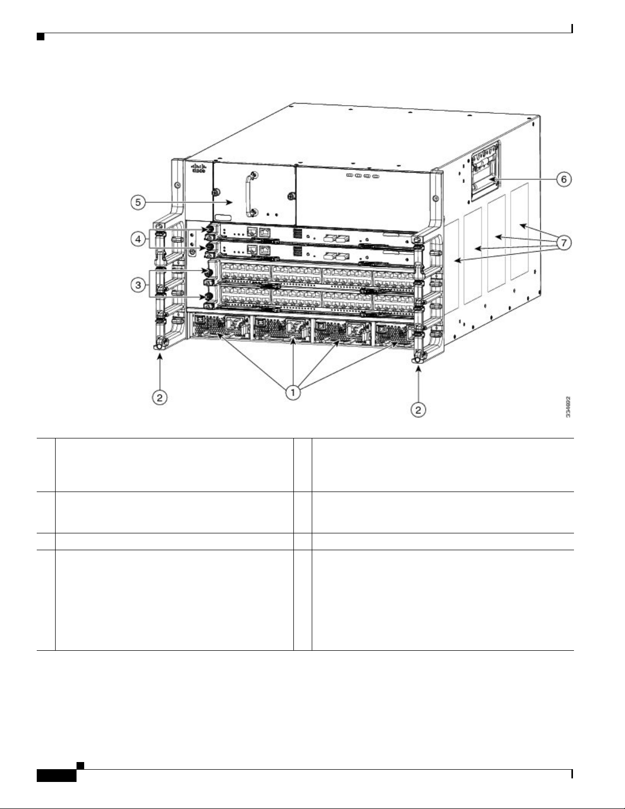
Cisco Nexus 7004 Switch
The Cisco Nexus 7004 chassis has four slots that allow for one or two supervisor modules and up to two
I/O modules. Additionally, the chassis holds a fan tray, up to four power supplies, and cable management
frames. Optionally, you can include a door and air filter. Figure 1-1 identifies these features as seen from
the front of the chassis.
OL-23069-07
Cisco Nexus 7000 Series Hardware Installation and Reference Guide
1-1
Page 16
Cisco Nexus 7000 Series
Chapter 1 Overview
Figure 1-1 Standard Hardware Features on the Front and Sides of the Cisco Nexus 7004 Chassis
1 Air intake areas for up to four AC or DC power
5 Fan tray
supplies (N7K-AC-3KW or N7K-DC-3KW) or blank
filler plates in place of missing power supplies to
maintain the designed airflow
2 Cable management side frames 6 Handles used for moving the chassis (reduce the chassis
weight to less than 120 lbs (54.4 kg) in order to use these
handles to lift the chassis)
4 I/O or NAM modules (1 to 2 modules in slots 3 to 4). 7 Air intake areas for supervisor and I/O modules
4 Supervisor modules (1 or 2 modules in slots 1 and 2).
These modules are of only one of the following types
(if installing two supervisor modules, both modules
must be the same type with the same amount of
memory):
• Supervisor 2 (N7K-SUP2)
• Supervisor 2 Enhanced (N7K-SUP2E)
1-2
Cisco Nexus 7000 Series Hardware Installation and Reference Guide
OL-23069-07
Page 17

Chapter 1 Overview
Note Figure 1-1 shows the Cisco Nexus 7004 chassis as it appears when it is fully configured before including
Cisco Nexus 7000 Series
cables for management and network connections. The systems that are not fully configured with the
maximum number of supervisor modules, I/O modules, or power supply units have blank panels installed
in place of the missing components to maintain the designed airflow for system cooling.
The I/O module slots hold one or two of the following types of modules:
• F2 Series I/O modules
–
48-port 1-/10-Gigabit SFP+ with XL option and FEX support (N7K-F248XP-25 and
N7K-F248XP-25E
–
48-port 1-/10-GBASE-T with XL option (N7K-F248XT-25E)
• F3 Series I/O modules
–
12-port 40-Gigabit QSFP+ (N7K-F312FQ-25)
• M1 Series I/O modules
–
48-port 10/100/1000 with XL option (N7K-M148GT-11L)
–
48-port 1-Gigabit Ethernet with XL option (N7K-M148GS-11L)
–
32-port 10-Gigabit Ethernet with XL option and FEX support (N7K-M132XP-12L)
1
)
Warning
–
8-port 10-Gigabit Ethernet with XL option (N7K-M108X2-12L)
• M2 Series I/O modules
–
24-port 10-Gigabit Ethernet with XL option and FEX support (N7K-M224XP-23L)
–
6-port 40-Gigabit Ethernet with XL option (N7K-M206XP-23L)
–
2-port 100-Gigabit Ethernet with XL option (N7K-M202XP-23L)
• Network Analysis modules (N7K-SM-NAM-K9)
You must install the Cisco Nexus 7004 chassis in a two- or four-post 19-inch EIA rack that meets the
following specifications:
• Mounting rails that conform to the English universal hole spacing as specified in
ANSI/EIA-310-D-1992.
• The minimum vertical rack space is 12.25 inches (31.1 cm) or 7 rack units (RU) for a single chassis
installation.
Install the Cisco Nexus 7004 chassis at the lowest possible RU on the rack for stability. If there are other
devices in the rack, install the heavier chassis below the lighter chassis.
Stability hazard. The rack stabilizing mechanism must be in place, or the rack must be bolted to the
floor before you slide the unit out for servicing. Failure to stabilize the rack can cause the rack to tip
over.
Statement 1048
OL-23069-07
1. The Cisco Nexus F2-Series 48-port 1/10-Gigabit SFP+ module supports all of the standard features of F2 modules and it
functions like an F2-series module with Layer 2 and Layer 3 enabled. These modules also support IPv6 DSCP-to-Queue
mapping.
Cisco Nexus 7000 Series Hardware Installation and Reference Guide
1-3
Page 18
Cisco Nexus 7000 Series
Cisco Nexus 7009 Switch
The Cisco Nexus 7009 chassis has 9 slots that allow for one or two supervisor modules and up to seven
I/O modules. Additionally, the chassis also holds up to five fabric modules, one fan tray, up to two power
supplies, and cable management frames. The chassis also has a front-mount bracket (an alternative
center-mount bracket can be ordered) and four positioning handles (two on each side) that you use to
position the chassis after you place it on a mechanical lift or bottom-support brackets. Optionally, you
can include a door and air intake frame.
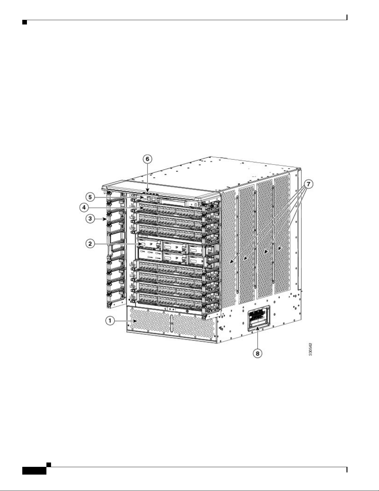
Figure 1-2 identifies the standard features on the front and sides of the Cisco Nexus 7009 chassis, and
Figure 1-3 identifies the standard features on the rear of the chassis.
Figure 1-2 Standard Hardware Features on the Front and Sides of the Cisco Nexus 7009 Chassis
Chapter 1 Overview
1-4
Cisco Nexus 7000 Series Hardware Installation and Reference Guide
OL-23069-07
Page 19
Chapter 1 Overview
Cisco Nexus 7000 Series
1 Air intake area for power supply units 5 Supervisor modules (1 or 2 modules in slots
1 and 2). These modules are of only one of
the following types (if installing two
supervisor modules, both modules must be
the same type with the same amount of
memory):
• Supervisor 1 (N7K-SUP1)
• Supervisor 2 (N7K-SUP2)
• Supervisor 2 Enhanced (N7K-SUP2E)
2 Fabric modules (up to 5) (N7K-C7009-FAB-2) 6 Cable management top hood with LEDs
3 Cable management side frame 7 Air intake areas for supervisor, I/O, and
fabric modules
4 I/O or NAM modules (1 to 7 modules in slots 3 to 9). 8 Handles used for adjusting placement of
chassis on mechanical lift
OL-23069-07
Cisco Nexus 7000 Series Hardware Installation and Reference Guide
1-5
Page 20
Cisco Nexus 7000 Series
Chapter 1 Overview
Figure 1-3 Standard Hardware Features on the Rear of a Cisco Nexus 7009 Chassis
1 Fan tray (1) 2 Power supplies (1 or 2)—these modules are a
combination of the following:
• 6 kW AC power supply
(N7K-AC-6.0KW)
• 7.5 kW AC power supply
(N7K-AC-7.5KW-INT [international
plugs])
(N7K-AC-7.5KW-US [US plugs])
• 6 kW DC power supply
(N7K-DC-6.0KW)
• Blank filler plate (installed in place of a
missing power supply to maintain the
designed airflow)
Note Figure 1-2 and Figure 1-3 show the Cisco Nexus 7009 chassis as it appears when it is fully configured
before including cables for management and network connections. The systems that are not fully
configured with the maximum number of supervisor modules, I/O modules, fabric modules, or power
supplies have blank panels installed in place of the missing components to maintain the designed airflow
for system cooling.
1-6
Cisco Nexus 7000 Series Hardware Installation and Reference Guide
OL-23069-07
Page 21

Chapter 1 Overview
The I/O module slots hold one or two of the following types of modules:
• F1 Series I/O modules
–
32-port 1- and 10-Gigabit Ethernet I/O modules (N7K-F132XP-15)
–
48-port 1-/10-GBASE-T with XL option (N7K-F248XT-25E)
• F2 Series I/O modules
–
48-port 1-/10-Gigabit SFP+ with XL option and FEX support (N7K-F248XP-25 and
N7K-F248XP-25E
• F3 Series I/O modules
–
12-port 40-Gigabit QSFP+ (N7K-F312FQ-25)
• M1 Series I/O modules
–
48-port 10/100/1000 I/O modules (N7K-M148GT-11)
–
48-port 10/100/1000 I/O modules with XL option (N7K-M148GT-11L)
–
48-port 1-Gigabit Ethernet I/O modules (N7K-M148GS-11)
–
48-port 1-Gigabit Ethernet I/O modules with XL option (N7K-M148GS-11L)
–
32-port 10-Gigabit Ethernet I/O modules with FEX support (N7K-M132XP-12)
1
)
Cisco Nexus 7000 Series
–
32-port 10-Gigabit Ethernet I/O modules with XL option and FEX support
(N7K-M132XP-12L)
–
8-port 10-Gigabit Ethernet I/O modules with XL option (N7K-M108X2-12L)
• M2 Series I/O modules
–
24-port 10-Gigabit Ethernet I/O modules with XL option and FEX support
(N7K-M224XP-23L)
–
6-port 40-Gigabit Ethernet I/O modules with XL option (N7K-M206XP-23L)
–
2-port 100-Gigabit Ethernet I/O modules with XL option (N7K-M202XP-23L)
• Network Analysis Modules (NAMs) (N7K-SM-NAM-K9
You must install the Cisco Nexus 7009 chassis in a two- or four-post 19-inch EIA rack that meets the
following specifications:
• Mounting rails that conform to the English universal hole spacing as specified in
ANSI/EIA-310-D-1992.
• The minimum vertical rack space is 24.5 inches (62.2 cm) or 14 rack units (RU) for a single chassis
installation (15 RU if you use the bottom support rails, which are required for center-mount
installations and optional for front-mount installations).
Install the Cisco Nexus 7009 chassis at the lowest possible RU on the rack for stability. If there are other
devices in the rack, install the heaviest chassis below the lighter chassis.
OL-23069-07
Warning
Stability hazard. The rack stabilizing mechanism must be in place, or the rack must be bolted to the
floor before you slide the unit out for servicing. Failure to stabilize the rack can cause the rack to tip
over.
Statement 1048
1. The Cisco Nexus F2-Series 48-port 1/10-Gigabit SFP+ module supports all of the standard features of F2 modules and it
functions like an F2-series module with Layer 2 and Layer 3 enabled. These modules also support IPv6 DSCP-to-Queue
mapping.
Cisco Nexus 7000 Series Hardware Installation and Reference Guide
1-7
Page 22
Cisco Nexus 7000 Series
Cisco Nexus 7010 System
The Cisco Nexus 7010 chassis has 10 slots that allow for two supervisor modules and up to eight I/O
modules. Additionally, the chassis holds up to five fabric modules, two system fan trays, two fabric fan
trays, up to three power supplies, and cable management frames. The chassis also has mounting brackets
and four positioning handles (two on each side) that you use to install the chassis after you position it
on a rack. Optionally, you can include an air filter and mid-frame doors.
Figure 1-4 identifies the standard features on the front and sides of the Cisco Nexus 7010 chassis,
Figure 1-5 identifies the optional features on the front side of the chassis, and Figure 1-6 identifies the
standard features on the rear of the chassis.
Figure 1-4 Standard Hardware Features on the Front and Sides of the Cisco Nexus 7010 Chassis
Chapter 1 Overview
1-8
Cisco Nexus 7000 Series Hardware Installation and Reference Guide
OL-23069-07
Page 23
Chapter 1 Overview
Cisco Nexus 7000 Series
1 Door for the cable management
area
5 Handles used to reposition the chassis (do not lift the chassis with these
handles—use a mechanical lift)
2 System status LEDs 6 I/O or NAM modules (1 to 8 modules in slots 1 to 4 and 7 to 10).
3 Cable management area (upper
routing portion can be removed if
necessary)
4 Rack-mount bracket (2) (one on
7 Supervisor modules (1 or 2 modules in slots 5 and 6). These modules are of only
one of the following types (if installing two supervisor modules, both modules
must be the same type with the same amount of memory):
• Supervisor 1 (N7K-SUP1)
• Supervisor 2 (N7K-SUP2)
• Supervisor 2 Enhanced (N7K-SUP2E)
8 Air intake (shown without the optional air filter)
each side)
Figure 1-5 Optional Hardware Features on the Front Side of the Cisco Nexus 7010 Chassis
OL-23069-07
1 Mid-frame door assembly 2 Air filter
Cisco Nexus 7000 Series Hardware Installation and Reference Guide
1-9
Page 24

Cisco Nexus 7000 Series
Chapter 1 Overview
Figure 1-6 Standard Hardware Features on the Back of the Cisco Nexus 7010 Chassis
1 Fan exhaust for the supervisor
and I/O modules
2 System fan trays (2)
(N7K-C7010-FAN-S) and
exhaust for the supervisor and
I/O modules
4 Fabric modules (up to 5) [N7K-C7010-FAB-1 or
N7K-C7010-FAB-2])
5 Power supply units (up to 3) and exhaust for the power supply
units—these modules are a combination of the following:
• 6 kW AC power supply (N7K-AC-6.0KW)
• 7.5 kW AC power supply (N7K-AC-7.5KW-INT
[international plugs] and N7K-AC-7.5KW-US [US plugs])
• 6 kW DC power supply (N7K-DC-6.0KW)
• Blank filler plate (replaces a missing power supply to
maintain the designed airflow)
3 Fabric fan trays (2)
(N7K-C7010-FAN-F) and
exhaust for the fabric modules
Note Figure 1-4 and Figure 1-6 show the Cisco Nexus 7000 Series chassis as it appears when it is fully
configured before including cables for connections to the Internet and the console. The systems that are
not fully configured with the maximum number of supervisor modules, I/O modules, fabric modules, or
power supplies have blank filler panels installed in place of the missing components to maintain the
designed airflow for system cooling.
1-10
Cisco Nexus 7000 Series Hardware Installation and Reference Guide
OL-23069-07
Page 25

Chapter 1 Overview
The I/O module slots hold one or two of the following types of modules:
• F1 Series I/O modules
–
32-port 1- and 10-Gigabit Ethernet I/O modules (N7K-F132XP-15)
–
48-port 1-/10-GBASE-T with XL option (N7K-F248XT-25E)
• F2 Series I/O modules
–
48-port 1-/10-Gigabit SFP+ with XL option and FEX support (N7K-F248XP-25 and
N7K-F248XP-25E
• F3 Series I/O modules
–
12-port 40-Gigabit QSFP+ (N7K-F312FQ-25)
• M1 Series I/O modules
–
48-port 10/100/1000 I/O modules (N7K-M148GT-11)
–
48-port 10/100/1000 I/O modules with XL option (N7K-M148GT-11L)
–
48-port 1-Gigabit Ethernet I/O modules (N7K-M148GS-11)
–
48-port 1-Gigabit Ethernet I/O modules with XL option (N7K-M148GS-11L)
–
32-port 10-Gigabit Ethernet I/O modules with FEX support (N7K-M132XP-12)
1
)
Cisco Nexus 7000 Series
–
32-port 10-Gigabit Ethernet I/O modules with XL option and FEX support
(N7K-M132XP-12L)
–
8-port 10-Gigabit Ethernet I/O modules with XL option (N7K-M108X2-12L)
• M2 Series I/O modules
–
24-port 10-Gigabit Ethernet I/O modules with XL option and FEX support
(N7K-M224XP-23L)
–
6-port 40-Gigabit Ethernet I/O modules with XL option (N7K-M206XP-23L)
–
2-port 100-Gigabit Ethernet I/O modules with XL option (N7K-M202XP-23L)
• Network Analysis Modules (NAMs) (N7K-SM-NAM-K9
You must install the Cisco Nexus 7010 system chassis in a four-post 19-inch EIA rack that meets the
following specifications:
• Mounting rails that conform to the English universal hole spacing as specified in
ANSI/EIA-310-D-1992.
• The minimum vertical rack space is 36.75 inches (93.3 cm) or 21 rack units (RU) for a single chassis
installation and 73.5 inches (186.6 cm) or 42 rack units for a dual-chassis installation. We
recommend that you use a 45 RU rack for a dual-chassis installation.
If you install one chassis, install it at the lowest possible RU on the rack for stability, as shown in
Figure 1-7. If you install two chassis in the same rack, install the bottom chassis first and then install the
other chassis on top as shown in Figure 1-8.
OL-23069-07
Warning
Stability hazard. The rack stabilizing mechanism must be in place, or the rack must be bolted to the
floor before you slide the unit out for servicing. Failure to stabilize the rack can cause the rack to tip
over.
Statement 1048
1. The Cisco Nexus F2-Series 48-port 1/10-Gigabit SFP+ module supports all of the standard features of F2 modules and it
functions like an F2-series module with Layer 2 and Layer 3 enabled. These modules also support IPv6 DSCP-to-Queue
mapping.
Cisco Nexus 7000 Series Hardware Installation and Reference Guide
1-11
Page 26

Cisco Nexus 7000 Series
Chapter 1 Overview
Figure 1-7 One Cisco Nexus 7010 Chassis Installed in a Four-Post Rack
1-12
Cisco Nexus 7000 Series Hardware Installation and Reference Guide
OL-23069-07
Page 27

Chapter 1 Overview
Cisco Nexus 7000 Series
Figure 1-8 Two Cisco Nexus 7010 Chassis Installed in a Four-Post Rack
Cisco Nexus 7018 System
The Cisco Nexus 7018 chassis has 18 slots that allow for two supervisor modules and up to 16 I/O
modules. The chassis also holds up to five fabric modules, two fan trays, up to four power supplies, and
a cable management system. The chassis also has a mounting bracket and four positioning handles (two
on each side) that you use to install the chassis after you position it on a rack. Optionally, you can include
a front door to protect the I/O cable connections.
Figure 1-9 identifies the standard features on the front and sides of the Cisco Nexus 7018 chassis,
Figure 1-10 identifies the components of the cable management system, Figure 1-11 identifies the
optional feature on the front side of the chassis, and Figure 1-12 identifies the standard features on the
rear of the chassis.
OL-23069-07
Cisco Nexus 7000 Series Hardware Installation and Reference Guide
1-13
Page 28

Cisco Nexus 7000 Series
Chapter 1 Overview
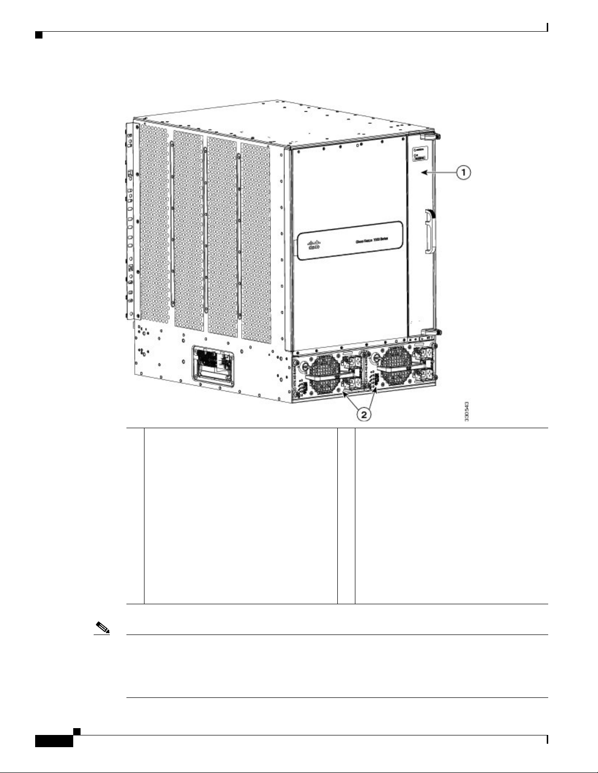
Figure 1-9 Standard Hardware Features on the Front and Sides of the Cisco Nexus 7018 Chassis
1 System status LEDs 5 Air intake for power supply units
2 Rack-mount brackets (2) 6 Air intake for the supervisor modules
and I/O modules
3 I/O or NAM modules (1 to 16 in slots 1 to 8 and slots 11 to 18). 7 Air intake for fabric modules
4 Supervisor modules (1 or 2 modules in slots 1 and 2). These modules are
of only one of the following types (if installing two supervisor modules,
both modules must be the same type with the same amount of memory):
• Supervisor 1 (N7K-SUP1)
• Supervisor 2 (N7K-SUP2)
• Supervisor 2 Enhanced (N7K-SUP2E)
Cisco Nexus 7000 Series Hardware Installation and Reference Guide
1-14
8 Handles used to reposition the chassis
(do not lift the chassis with these
handles—use a mechanical lift)
OL-23069-07
Page 29

Chapter 1 Overview
Cisco Nexus 7000 Series
Figure 1-10 Cable Management System for the Cisco Nexus 7018 Chassis
OL-23069-07
1 System status LEDs (these LEDs show the
3 Upper cable management assemblies
system status displayed by the chassis LEDs)
2 Top hood 4 Lower cable management assemblies
Cisco Nexus 7000 Series Hardware Installation and Reference Guide
1-15
Page 30

Cisco Nexus 7000 Series
Chapter 1 Overview
Figure 1-11 Optional Front Door for the Cisco Nexus 7018 Chassis
1-16
1 Front doors 2 Air intake frame for power supply units
Cisco Nexus 7000 Series Hardware Installation and Reference Guide
OL-23069-07
Page 31

Chapter 1 Overview
Cisco Nexus 7000 Series
Figure 1-12 Standard Hardware Features on the Back of the Cisco Nexus 7018 Chassis
OL-23069-07
Cisco Nexus 7000 Series Hardware Installation and Reference Guide
1-17
Page 32

Cisco Nexus 7000 Series
Chapter 1 Overview
1 Fabric modules (up to 5) (N7K-C7018-FAB-1 or
4 Fan exhaust for fabric modules
N7K-C7018-FAB-2)
2 Power supply units (up to 4)—these modules are a
combination of the following:
• 6 kW AC power supply (N7K-AC-6.0KW)
• 7.5 kW AC power supply
5 Fan exhaust for supervisor and I/O
modules
(N7K-AC-7.5KW-INT [international plugs])
(N7K-AC-7.5KW-US [US plugs])
• 6 kW DC power supply (N7K-DC-6.0KW)
• Blank filler plate (replaces missing power
supplies to maintain the designed airflow)
3 Fan trays for cooling the supervisor, I/O, and fabric
modules
6 Handles used to reposition the chassis
(do not lift the chassis with these
handles—use a mechanical lift)
Note Figure 1-9 and Figure 1-12 show the Cisco Nexus 7018 chassis as it appears when it is fully configured
before including cables for connections to the Internet and the console. The systems that are not fully
configured with the maximum number of supervisor modules, I/O modules, fabric modules, or power
supplies have blank panels installed in place of the missing components to maintain the designed airflow
for system cooling.
The I/O module slots hold one or two of the following types of modules:
• F1 Series I/O modules
–
32-port 1- and 10-Gigabit Ethernet I/O modules (N7K-F132XP-15)
–
48-port 1-/10-GBASE-T with XL option (N7K-F248XT-25E)
• F2 Series I/O modules
–
48-port 1-/10-Gigabit SFP+ with XL option and FEX support (N7K-F248XP-25 and
N7K-F248XP-25E
• F3 Series I/O modules
–
12-port 40-Gigabit QSFP+ (N7K-F312FQ-25)
• M1 Series I/O modules
–
48-port 10/100/1000 I/O modules (N7K-M148GT-11)
–
48-port 10/100/1000 I/O modules with XL option (N7K-M148GT-11L)
–
48-port 1-Gigabit Ethernet I/O modules (N7K-M148GS-11)
–
48-port 1-Gigabit Ethernet I/O modules with XL option (N7K-M148GS-11L)
–
32-port 10-Gigabit Ethernet I/O modules with FEX support (N7K-M132XP-12)
–
32-port 10-Gigabit Ethernet I/O modules with XL option and FEX support
1
)
(N7K-M132XP-12L)
–
8-port 10-Gigabit Ethernet I/O modules with XL option (N7K-M108X2-12L)
1-18
1. The Cisco Nexus F2-Series 48-port 1/10-Gigabit SFP+ module supports all of the standard features of F2 modules and it
functions like an F2-series module with Layer 2 and Layer 3 enabled. These modules also support IPv6 DSCP-to-Queue
mapping.
Cisco Nexus 7000 Series Hardware Installation and Reference Guide
OL-23069-07
Page 33

Chapter 1 Overview
Cisco Nexus 7000 Series
• M2 Series I/O modules
–
24-port 10-Gigabit Ethernet I/O modules with XL option and FEX support
(N7K-M224XP-23L)
–
6-port 40-Gigabit Ethernet I/O modules with XL option (N7K-M206XP-23L)
–
2-port 100-Gigabit Ethernet I/O modules with XL option (N7K-M202XP-23L)
• Network Analysis Modules (NAMs) (N7K-SM-NAM-K9
You must install the Cisco Nexus 7018 chassis in a four-post 19-inch EIA rack that meets the following
specifications:
• Mounting rails that conform to the English universal hole spacing as specified in
ANSI/EIA-310-D-1992.
• The minimum vertical rack space is 43.75 inches (111.1 cm) or 25 rack units (RU) for a single
chassis installation and 87.5 inches (222.2 cm).
Install the Cisco Nexus 7018 chassis at the lowest possible RU on the rack for stability, as shown in
Figure 1-13. If there is another device in the rack, install the heaviest one at the bottom.
Warning
Stability hazard. The rack stabilizing mechanism must be in place, or the rack must be bolted to the
floor before you slide the unit out for servicing. Failure to stabilize the rack can cause the rack to tip
over.
Statement 1048
OL-23069-07
Cisco Nexus 7000 Series Hardware Installation and Reference Guide
1-19
Page 34

Preparing the Site
Chapter 1 Overview
Figure 1-13 Cisco Nexus 7018 Chassis Installed in a Four-Post Rack
Preparing the Site
Warning
Cisco Nexus 7000 Series Hardware Installation and Reference Guide
1-20
Installation of the equipment must comply with local and national electrical codes.
Before you can install a Cisco Nexus 7000 Series system, you must prepare the site for the installation.
You must make sure that the altitude, temperature, humidity, air quality, airflow, electromagnetic and
radio frequency interference, floor structure, power, and earth grounding of the installation site all meet
the requirements of the Cisco Nexus 7000 Series system that you are installing. In addition, you must
set up a rack or cabinet that can hold the number of chassis that you are installing. To see the general
Statement 1074
OL-23069-07
Page 35

Chapter 1 Overview
requirements for this system, see Appendix A, “Technical Specifications.” To see detailed information
about preparing the data center for the installation, see the Cisco Nexus 7000 Series Site Preparation
Guide.
Safety Guidelines
Safety Guidelines
Warning
Only trained and qualified personnel should be allowed to install, replace, or service this equipment.
Statement 1030
The prerequisites listed for any procedure are required conditions that you must verify before you start
that procedure. If the prerequisites have not been met, you must satisfy those requirements before
carrying out the procedure.
Safety warnings appear in this publication wherever procedures present conditions that could endanger
you or others installing this system. Adhering to these warnings and following their recommended
actions are required actions for these procedures. For regulatory compliance and safety information on
these warnings, see the Cisco Nexus 7000 Series Regulatory Compliance and Safety Information
document.
Installation and Connection Guidelines
After you fully prepare the site as specified in the Cisco Nexus 7000 Series Site Preparation Guide,
install a two-post 19-inch EIA rack for Cisco Nexus 7004 and 7009 chassis or a four-post 19-inch EIA
rack for all chassis. To install the system, you must make sure that you have the proper mounting brackets
(front-mount or center-mount brackets) installed on the chassis, move the chassis to the rack, elevate it
to the lowest possible RU for that chassis, and fasten the chassis to the rack. With the chassis fastened
to the rack, you can ground the chassis, install its cable management frames, install the optional door
and optional air filter, and connect the switch to the console and network. For detailed instructions on
installing a Cisco Nexus 7000 Series switch, see the following chapters:
OL-23069-07
• Chapter 2, “Installing a Cisco Nexus 7004 Chassis”
• Chapter 2, “Installing a Cisco Nexus 7004 Chassis”
• Chapter 3, “Installing a Cisco Nexus 7009 Chassis”
• Chapter 4, “Installing a Cisco Nexus 7010 Chassis”
• Chapter 5, “Installing a Cisco Nexus 7018 Chassis”
• Chapter 6, “Installing Power Supplies”
For detailed instructions on connecting the switch to the console and network, see Chapter 7,
“Connecting the Cisco Nexus 7000 Series Switch to the Network.”
Caution Do not use the handles on the side of the chassis to lift the Cisco Nexus 7009, 7010, or 7018 chassis or
a fully loaded Cisco Nexus 7004 chassis (you can use these handles to lift a Cisco Nexus 7004 chassis
if you remove the power supplies so that the chassis weighs less than 120 pounds [52 kg]). For the Cisco
Nexus 7009, 7010, and 7018, use these handles only for adjusting the position of the chassis while the
chassis rests on a platform or bottom-support rails.
Cisco Nexus 7000 Series Hardware Installation and Reference Guide
1-21
Page 36

Managing the System Hardware
If you are replacing Fabric 1 modules with Fabric 2 modules (Cisco Nexus 7010 and 7018 models only),
you must replace all of the Fabric 1 modules with Fabric 2 modules or the Fabric 2 modules will perform
like Fabric 1 modules. If you power up a switch with both Fabric 1 and Fabric 2 modules installed, only
the Fabric 2 modules will power up.
Note The Cisco NX-OS software may require 8 GB of memory, depending on the software version you use
and the software features that you enable. If your switch has Supervisor 1 modules with only 4 GB of
memory, then you might need to upgrade the modules to 8 GB of memory by using the 8 GB supervisor
upgrade kit (N7K-SUP1-8GBUPG=). This upgrade is not needed for switches that have at least 8 GB of
memory (which includes Supervisor 1 modules with 8 GB and all Supervisor 2 and Supervisor 2E
modules). To verify the amount of memory installed in the supervisor modules or to upgrade the
memory, see the “Upgrading Memory for Supervisor 1 Modules” section on page 10-29.
Managing the System Hardware
After the Cisco Nexus 7000 Series system is installed and operating, you can use the Cisco NX-OS
operating system to manage the system hardware. These management functions include displaying
system and module information, setting the power supply modes, and managing module functions. For
more information about these functions, see Chapter 8, “Managing the Switch Hardware.”
Chapter 1 Overview
Replacing Components
While the Cisco Nexus 7000 Series system is operational, you can replace any one of the following
components if they are redundant:
• Power supply
• Supervisor module
• Fabric module (Cisco Nexus 7009, 7010, and 7018 models only)
• I/O modules
• Fan trays
For detailed information on replacing these components, see Chapter 10, “Installing or Replacing
Components.”
1-22
Cisco Nexus 7000 Series Hardware Installation and Reference Guide
OL-23069-07
Page 37

CHA PTER
2
Installing a Cisco Nexus 7004 Chassis
This chapter describes how to install a new or relocated Cisco Nexus 7004 chassis in a rack or cabinet.
For information about installing other Cisco Nexus 7000 Series chassis or power supplies, see the
following chapters:
• Chapter 3, “Installing a Cisco Nexus 7009 Chassis”
• Chapter 4, “Installing a Cisco Nexus 7010 Chassis”
• Chapter 5, “Installing a Cisco Nexus 7018 Chassis”
• Chapter 6, “Installing Power Supplies”
This chapter includes the following sections:
• Preparing to Install the Switch, page 2-1
• Installing the Chassis, page 2-4
• Grounding the Cisco Nexus 7004 Chassis, page 2-9
• Installing the Cable Management Frames, page 2-11
• Installing USB Storage Media in a Supervisor 2 or 2E Module, page 2-12
• Installing the Air Filter, page 2-13
Preparing to Install the Switch
This section includes the following topics:
• Required Tools, page 2-2
• Installing a Rack or Cabinet, page 2-2
• Unpacking and Inspecting a New Switch, page 2-3
Note You must set up one two- or four-post, 19-inch EIA rack or cabinet before you can install the Cisco
Nexus 7004 chassis. Make sure that you order the rack or cabinet and have it delivered before installing
the chassis.
Cisco Nexus 7000 Series Hardware Installation and Reference Guide
OL-23069-07
2-1
Page 38

Preparing to Install the Switch
Required Tools
Chapter 2 Installing a Cisco Nexus 7004 Chassis
Before you install the Cisco Nexus 7004 chassis into a rack, make sure that you have the Cisco Nexus
7004 Accessory Kit (see the “Cisco Nexus 7004 Switch Accessory Kit” section on page C-1 for the
contents list) and the following equipment, which are not provided by Cisco:
• Mechanical lift capable of lifting 150 pounds (68 kg)
Note This lift is required only if moving or lifting a fully loaded chassis that weighs at least 120
pounds (54.4 kg). If you remove the power supplies, the chassis weighs 93 pounds (42.2 kg)
or less and you can manually lift it with two persons.
• Number 1 Phillips-head screwdriver with torque capability
• 3/16-inch flat-blade screwdriver
• Crimping tool
• Wire stripping tool
• Tape measure and level
• Grounding wire—Use a wire size that meets local and national installation requirements. Depending
on the power supply and system, a 12 AWG to 6 AWG copper conductor is required for U.S.
installations. We recommend that you use commercially available 6 AWG wire. The length of the
grounding wire depends on the proximity of the switch to proper grounding facilities.
Note For a list of tools required to assemble and secure the two- or four-post rack or cabinet, see the
documentation that the manufacturer shipped with the rack or cabinet.
Installing a Rack or Cabinet
Before you install the Cisco Nexus 7004 chassis, you must install a standard two- or four-post, 19-inch
EIA data center rack (or a cabinet that contains such a rack) that meets the requirements listed in the
Cisco Nexus 7000 Series Site Preparation Guide. To maximize safety, you should do the following for
the rack:
• Bolt the rack to the concrete subfloor before moving the Cisco Nexus 7004 chassis onto it.
Warning
Stability hazard. The rack stabilizing mechanism must be in place, or the rack must be bolted to the
floor before you slide the unit out for servicing. Failure to stabilize the rack can cause the rack to tip
over.
Statement 1048
• If the rack has bonded construction, connect it to the earth ground to enable you to easily ground the
system components that you install and to ground your ESD wrist strap. This step minimizes the
chance of electrostatic discharge when you handle ungrounded components while working with
them.
Be sure that the rack includes AC power receptacles with the amperage required for the power supplies
that you will be installing in the chassis. For 3-kW power supplies, you must have 20-A circuits.
2-2
Warning
Cisco Nexus 7000 Series Hardware Installation and Reference Guide
Take care when connecting units to the supply circuit so that wiring is not overloaded.
Statement 1018
OL-23069-07
Page 39

Chapter 2 Installing a Cisco Nexus 7004 Chassis
For instructions on setting up the rack, see the documentation that the manufacturer shipped with the
rack.
Unpacking and Inspecting a New Switch
Caution When you handle the Cisco Nexus 7004 chassis or its components, you must follow ESD protocol at all
times to prevent ESD damage. This protocol includes but is not limited to wearing an ESD wrist strap
that you connect to the earth ground.
Before you install a new Cisco Nexus 7004 chassis, you need to unpack and inspect it to be sure that you
have all the items that you ordered and verify that the switch was not damaged during shipment. If
anything is damaged or missing, contact your customer representative immediately.
Tip Do not discard the shipping container when you unpack the Cisco Nexus 7004 system. Flatten the
shipping cartons and store them with the pallet used for the system. If you need to move or ship the
system in the future, you will need these containers. For repacking instructions, see Appendix E,
“Repacking the Cisco Nexus 7000 Series Switch for Shipment.”
Preparing to Install the Switch
To inspect the shipment, follow these steps:
Step 1 Compare the shipment to the equipment list that is provided by your customer service representative and
verify that you have received all of the ordered items. The shipment should include boxes for the
following:
• System chassis, which includes the following installed components:
–
2 supervisor modules
–
1 or 2 I/O modules
–
1 fan tray
–
2 to 4 power supply units
–
Blank filler plates for any missing supervisor modules, I/O modules, or power supply modules
• Cisco Nexus 7004 system accessory kit
To see a list of what is in the accessory kit, see the “Cisco Nexus 7004 Switch Accessory Kit” section
on page C-1.
• Cable management frames
• Front door (optional)
• Air filter (optional)
Step 2 Check the contents of each box or package for damage.
Step 3 If you notice any discrepancies or damage, send the following information to your customer service
representative by E-mail:
• Invoice number of the shipper (see the packing slip)
• Model and serial number of the missing or damaged unit
OL-23069-07
Cisco Nexus 7000 Series Hardware Installation and Reference Guide
2-3
Page 40

Installing the Chassis
• Description of the problem and how it affects the installation
Installing the Chassis
This section describes how to install the Cisco Nexus 7004 chassis in a rack or cabinet. These installation
steps include checking for installation prerequisites, setting up the center-mount brackets if needed,
removing the power supplies from the chassis if lifting the chassis manually, and installing the chassis
in a rack. When you finish this task, you can connect the chassis to the earth ground, install the cable
management frames, install the front door (optional), and reinstall any removed power supplies.
Caution You must use a mechanical lift whenever lifting a device over 120 pounds (54.4 kg). A fully loaded
chassis can weigh up to 137 pounds (62 kg). If you prefer to lift the chassis manually, you must remove
the power supplies and use at least two persons to lift it.
This section includes the following topics:
Chapter 2 Installing a Cisco Nexus 7004 Chassis
• Prerequisites for Installing the Chassis, page 2-4
• Installing the Center-Mount Brackets, page 2-5
• Installing the Chassis in a Rack, page 2-6
Prerequisites for Installing the Chassis
Before you install the chassis, you must make sure that the following items are available for the
installation:
• Data center ground is accessible where you are installing the Cisco Nexus 7004 chassis.
• Two- or four-post, 19-inch EIA rack or cabinet that includes such a rack.
For more information on the rack or cabinet, see the “Installing a Rack or Cabinet” section on
page 2-2.
Warning
Stability hazard. The rack stabilizing mechanism must be in place, or the rack must be bolted to the
floor before you slide the unit out for servicing. Failure to stabilize the rack can cause the rack to tip
over.
Statement 1048
2-4
Cisco Nexus 7000 Series Hardware Installation and Reference Guide
OL-23069-07
Page 41

Chapter 2 Installing a Cisco Nexus 7004 Chassis
Installing the Chassis
Warning
To prevent bodily injury when mounting or servicing this unit in a rack, you must take special
precautions to ensure that the system remains stable. The following guidelines are provided to
ensure your safety:
• This unit should be mounted at the bottom of the rack if it is the only unit in the rack.
• When mounting this unit in a partially filled rack, load the rack from the bottom to the top with the heaviest
component at the bottom of the rack.
• If the rack is provided with stabilizing devices, install the stabilizers before mounting or servicing the unit in
the rack.
• Center-mount brackets (2) and M4 x 6 mm screws (12) if you need to center the chassis on the rack.
Statement 1006
If you are mounting the front of the chassis on to the rack (typical installation), then you do not need
the center-mount brackets.
Installing the Center-Mount Brackets
Before you install a Cisco Nexus 7004 chassis, you need to determine whether you need to mount the
front of the chassis or the center of the chassis to the rack. The chassis is already set up for mounting its
front to the rack, but you can include center-mount brackets to position the front of the chassis 5.7 inches
(14.4 cm) in front of the rack.
Note If you need to install the center-mount brackets, you must separately order the Cisco Nexus 7009 Rack
Mount Kit (part number is N7K-C7004-RMK).
To install the center-mount brackets on the chassis, follow these steps:
Step 1 Align one of two center-mount brackets so that its six screw holes align to six screw holes on the side of
the chassis as shown in Figure 2-1.
OL-23069-07
Cisco Nexus 7000 Series Hardware Installation and Reference Guide
2-5
Page 42

Installing the Chassis
Chapter 2 Installing a Cisco Nexus 7004 Chassis
Figure 2-1 Installing Center-Mount Brackets on the Chassis
1 Center mount bracket (left and right versions) 2 Six M4 x 6 mm screws for each bracket
Step 2
Use a Phillips-head screw driver to secure the bracket to the chassis with the six M4 x 6 mm screws.
Tighten each screw to 11.5 to 15 in-lbs (1.3 to 1.7 N·m).
Step 3 Repeat steps 1 and 2 to install the other center-mount bracket on the other side of the chassis.
Installing the Chassis in a Rack
Before you install the chassis in the rack, you must determine how you are going to lift the chassis to its
position on the rack. You can either lift the chassis with a mechanical lift and slide it on top of another
installed Cisco Nexus 7004 chassis, or you can lighten the chassis and lift it manually into position with
a couple of people. To lighten the chassis for lifting, you can remove the power supplies so that the
chassis weighs no more than 93 pounds (42 kg) and can be lifted by two people.
After lifting the chassis into position, you fasten it to the rack, and replace any power supplies that you
might have removed earlier.
To install a Cisco Nexus 7004 chassis in a two- or four-post rack or cabinet, follow these steps:
Step 1 Prepare the chassis for moving by doing one of the following:
2-6
Warning
Cisco Nexus 7000 Series Hardware Installation and Reference Guide
To prevent personal injury or damage to the chassis, never attempt to lift or tilt the chassis using the
handles on modules (such as power supplies, fans, or cards); these types of handles are not designed
to support the weight of the unit.
Statement 1032
OL-23069-07
Page 43

Chapter 2 Installing a Cisco Nexus 7004 Chassis
Caution To move the chassis, either use the chassis handles (one found on each side) or push on the sides or edges
of the chassis without touching any of the modules or module handles.
• To move the chassis with a mechanical lift, position the lift at the elevation of the chassis on its
shipping pallet (or no more than 0.25 inches [0.64 cm] below the level of the pallet) and use two
persons to push the chassis fully onto the lift.
• To move the chassis manually, remove the power supplies as explained in one of the following
sections and then use two persons to lift the chassis:
–
To remove an AC power supply, see the “Removing a 3-kW AC Power Supply Unit During
Operations” section on page 10-3.
–
To remove a DC power supply, see the “Removing a 3-kW DC Power Supply Unit During
Operations” section on page 10-9.
Note We do not recommend that you remove any of the supervisor modules, I/O modules, or the fan
tray to make the chassis easier to lift because that removal can put those modules at risk of being
damaged. If you do remove any of those modules, be sure to have antistatic pads or antistatic
bags to hold these modules until you are ready to reinstall them in the chassis.
Installing the Chassis
Step 2 Lift the chassis to its position on a rack in one of the following ways:
• If you use a mechanical lift, position the chassis next to the front of another Cisco Nexus 7004
chassis already installed in the rack, elevate the new chassis to the level of the installed chassis (or
no more than 0.25 inches [0.64 cm] above the installed chassis, use two persons to align the back
side of the new chassis to the opening between the two front posts of the rack and push the chassis
into the installed chassis until the chassis mounting brackets come in contact with the rack mounting
rails.
• If you are lifting the chassis manually, use two or more persons to move the back end of the chassis
through the front posts until the chassis mounting brackets come in contact with the mounting rails
on the rack, lift the chassis to the lowest possible RU for it on the rack, and align the screw holes in
the chassis mounting brackets to the rack mounting rails.
Caution Use two persons to lift the chassis by using the handle on each side of the chassis. Do not use the handles
on any of the modules installed on the chassis to lift or move the chassis—these handles are for only
removing or installing the modules.
Step 3 Use five M6 x 19 mm screws (or 12-24 x 3/4 inch screws) to fasten each side of the chassis to the rack.
Tighten each of the 10 screws to 40 in. lbs (4.5 N.m) (see Figure 2-2).
OL-23069-07
Cisco Nexus 7000 Series Hardware Installation and Reference Guide
2-7
Page 44

Installing the Chassis
Chapter 2 Installing a Cisco Nexus 7004 Chassis
Figure 2-2 Mounting the Cisco Nexus 7004 Chassis on a Rack
2-8
1 Handles used to adjust the chassis placement
or to lift a chassis that weighs less than 120
pounds (54.4 kg).
Step 4
If you removed any power supplies, replace them as explained in one of the following sections:
• To install an AC power supply unit, see the “Installing a 3-kW AC Power Supply Unit During
Operations” section on page 10-3.
• To install a DC power supply unit, see the “Installing a 3-kW DC Power Supply Unit During
Operations” section on page 10-10.
Cisco Nexus 7000 Series Hardware Installation and Reference Guide
2 Five M4 x 6 mm Phillips-head screws used to
attach each front-mount or center-mount
bracket to a mounting rail (use a total of 12
screws for two brackets).
OL-23069-07
Page 45

Chapter 2 Installing a Cisco Nexus 7004 Chassis
Grounding the Cisco Nexus 7004 Chassis
The Cisco Nexus 7004 switch is fully grounded as soon as you connect the chassis and the power
supplies to the earth ground in the following ways:
• You connect the chassis to either a grounded and fully bonded rack or to the data center ground. This
ground connection is active even when the power supplies are not installed.
Note The system ground, also referred to as the network equipment building system (NEBS) ground,
provides additional grounding for EMI shielding requirements and for the low-voltage supplies
(DC-DC converters) on the modules. This grounding system is active even when the AC power
cables are not connected to the system.
• You connect the AC power supplies to the earth ground automatically when you connect an AC
power supply to an AC power source.
• You connect the DC power supplies to the earth ground before connecting the power supplies to the
DC power source (see the “Connecting a DC Power Supply Directly to DC Power Sources” section
on page 6-10).
This section includes the following topics:
Grounding the Cisco Nexus 7004 Chassis
• Prerequisites for Grounding the Chassis, page 2-9
• Connecting the System Ground, page 2-9
• Connecting Your ESD Wrist Strap to the Chassis, page 2-11
Prerequisites for Grounding the Chassis
Before you can ground the chassis, you must have a connection to the earth ground for the data center
building. If you installed the Cisco Nexus 7004 chassis into a bonded rack (see the rack manufacturer’s
instructions for more information) that now has a connection to the data center earth ground, you can
ground the chassis by connecting its grounding port to the rack. Otherwise, you must connect the chassis
grounding port directly to the data center ground.
Connecting the System Ground
After you have moved the chassis into the rack or cabinet, you are ready to connect the system to the
data center earth ground. After you ground the chassis, you can ground your ESD wrist strap by
connecting it to the chassis.
To connect the system ground to the data center earth ground, follow these steps:
Step 1 Use a wire-stripping tool to remove approximately 0.75 inch (19 mm) of the covering from the end of
the grounding wire.
Step 2 Insert the stripped end of the grounding wire into the open end of the grounding lug as shown in
Figure 2-3.
OL-23069-07
Cisco Nexus 7000 Series Hardware Installation and Reference Guide
2-9
Page 46

Grounding the Cisco Nexus 7004 Chassis
334693
1
2
Figure 2-3 Inserting the Grounding Wire in the Grounding Lug
1 NRTL listed 45-degree grounding lug 2 Grounding cable with 0.75 in. (19 mm) of insulation
Step 3 Use the crimping tool to crimp the lug to the grounding wire. Verify that the ground wire is securely
attached to the ground lug by attempting to pull the wire out of the crimped lug.
Step 4 Remove the adhesive label from the system grounding pad on the chassis, secure the grounding wire lug
to the grounding pad with two M4 screws, and tighten the screws to 11.5 to 15 in-lb (1.3 to 1.7 N·m).
Callout 1 in Figure 2-4 shows the location of the grounding pad on the front side of the chassis.
Chapter 2 Installing a Cisco Nexus 7004 Chassis
stripped from the end
Note Be sure that the grounding lug and wire do not block the ESD port by positioning the lug and wire
connection above the grounding port.
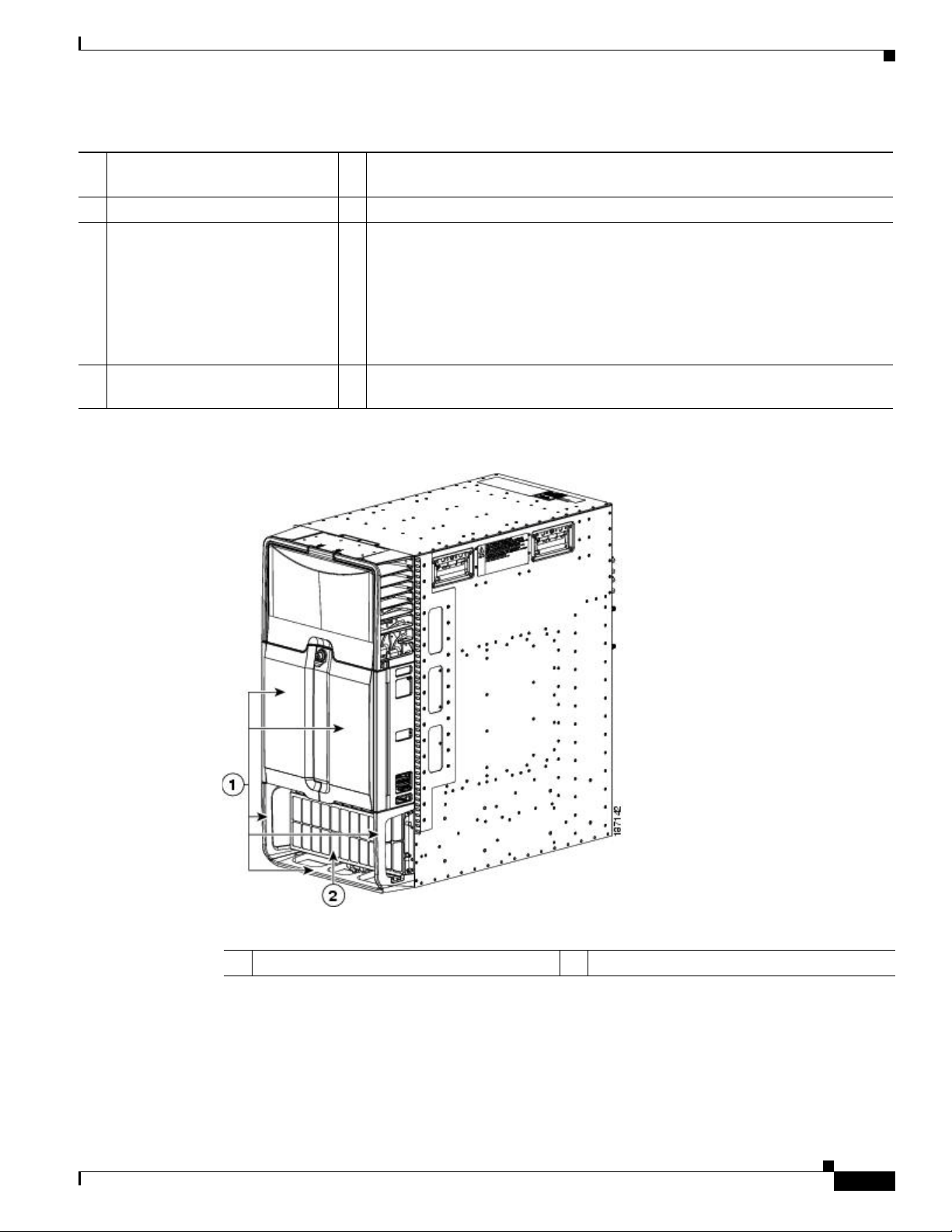
Figure 2-4 Grounding Pad and ESD Port Locations on the Cisco Nexus 7004 Chassis
1 Grounding pad 2 ESD port
Cisco Nexus 7000 Series Hardware Installation and Reference Guide
2-10
OL-23069-07
Page 47

Chapter 2 Installing a Cisco Nexus 7004 Chassis
Step 5 Prepare the other end of the grounding wire and connect it to an appropriate grounding point in your site
to ensure an adequate earth ground for the switch. If the rack is grounded, connect the grounding wire
as explained in the documentation provided by the vendor for the rack.
Connecting Your ESD Wrist Strap to the Chassis
After you connect the chassis to the data center earth ground, you can ground your ESD wrist strap by
plugging it into the ESD port shown by Callout 2 in Figure 2-4 on page 2-10.
Installing the Cable Management Frames
After you have fastened the chassis to the rack, you can fasten the cable management frames to the front
of the chassis.
To fasten the cable management frames to the chassis, follow these steps:
Installing the Cable Management Frames
Step 1 Align the guide guide pin on one of the two cable management frames to a guide-pin hole of the same
size on the front-mounting bracket that is already attached to the chassis. The top of the frame should be
at the same level as the top of the chassis (see Figure 2-5).
OL-23069-07
Cisco Nexus 7000 Series Hardware Installation and Reference Guide
2-11
Page 48

Installing USB Storage Media in a Supervisor 2 or 2E Module
Figure 2-5 Installing the Cable Management Frames on a Cisco Nexus 7004 Chassis
Chapter 2 Installing a Cisco Nexus 7004 Chassis
1 Guide pins on the cable management
frame aligned to two holes in the
2 Three M3 x 10 mm screws used to fasten the frame
to the chassis (total of six screws for two frames).
front-mount bracket.
Step 2 Fasten the frame to the chassis with three M3 x 10 mm screws (see Callout 2 in Figure 2-5). Tighten the
screws to 5 to 7 in-lb (0.56 to 0.79 N.m).
Step 3 Repeat Steps 1 and 2 to install the other cable management frame to the chassis.
Installing USB Storage Media in a Supervisor 2 or 2E Module
Each Supervisor 2 or 2E module on a Cisco Nexus 7004 switch has a USB drive installed in the LOG
FLASH reader. The Slot0 port is left empty, but you can optionally install a USB drive in the that port.
To allow this storage media to function with the USB port, you must make sure that it is either already
formatted for the port before installing it or format it after installing it.
Note The LOG FLASH and Slot0 USB ports use different formats for their data.
2-12
Cisco Nexus 7000 Series Hardware Installation and Reference Guide
OL-23069-07
Page 49

Chapter 2 Installing a Cisco Nexus 7004 Chassis
To install storage media in a supervisor module, follow these steps:
Step 1 Insert the USB drive in the LOG FLASH or SLOT0 port.
Step 2 Wait for the reader or port LED to turn green and for a message to appear on the console as follows:
• If you are installing a USB drive into the log flash reader, the message will end with
“logflash:online.”
• If you are installing a USB drive into the expansion flash reader, the message will end with
“slot0:online.”
• If you see an “offline” message or do not see a message, either the USB drive is not fully inserted
or it is improperly formatted.
Make sure that the USB drive is fully inserted inside the reader. If it is fully inserted, either format
the card (see the Cisco Nexus 7000 Series NX-OS Fundamentals Configuration Guide) or replace
the USB drive with another that is properly formatted for the reader.
Installing the Air Filter
Installing the Air Filter
The Cisco Nexus 7004 air filter is an optional feature (part number N7K-C7004-FAN=). To install an air
filter, follow these steps:
Step 1 Place the air filter over the air intake area on the right side of the chassis and align the eight screw holes
in the filter to screw holes in the chassis.
Step 2 Fasten the air filter to the chassis using eight M3 x 5 mm screws that came with the air filter.. Tighten
the screws to 5 to 7 in-lb (0.56 to 0.79 N.m).
OL-23069-07
Cisco Nexus 7000 Series Hardware Installation and Reference Guide
2-13
Page 50

Installing the Air Filter
Chapter 2 Installing a Cisco Nexus 7004 Chassis
2-14
Cisco Nexus 7000 Series Hardware Installation and Reference Guide
OL-23069-07
Page 51

CHA PTER
3
Installing a Cisco Nexus 7009 Chassis
This chapter describes how to install a new or relocated Cisco Nexus 7009 chassis in a rack or cabinet.
For information about installing other Cisco Nexus 7000 Series chassis or power supplies, see the
following chapters:
• Chapter 2, “Installing a Cisco Nexus 7004 Chassis”
• Chapter 4, “Installing a Cisco Nexus 7010 Chassis”
• Chapter 5, “Installing a Cisco Nexus 7018 Chassis”
• Chapter 6, “Installing Power Supplies”
This chapter includes the following sections:
• Preparing to Install the Switch, page 3-1
• Installing the Bottom-Support Rails on the Rack, page 3-4
• Installing the Chassis, page 3-11
• Grounding the Cisco Nexus 7009 Chassis, page 3-19
• Installing the Cable Management Frames, page 3-24
• Installing the Front Door and Air Intake Frame, page 3-27
• Installing Storage Media in a Supervisor Module, page 3-35
Preparing to Install the Switch
This section includes the following topics:
• Required Tools, page 3-2
• Installing a Rack or Cabinet, page 3-2
• Unpacking and Inspecting a New Switch, page 3-3
Note You must set up a two- or four-post, 19-inch EIA rack or cabinet before you can install the Cisco Nexus
7009 chassis. Make sure that you order the rack or cabinet and have it delivered before installing the
chassis.
Cisco Nexus 7000 Series Hardware Installation and Reference Guide
OL-23069-07
3-1
Page 52

Preparing to Install the Switch
Required Tools
Note These tools and equipment do not ship with the chassis.
Chapter 3 Installing a Cisco Nexus 7009 Chassis
Before you install the Cisco Nexus 7009 chassis into a rack, make sure that you have the following tools
and equipment:
• Mechanical lift capable of lifting 300 pounds (136 kg)
• Number 1 Phillips screwdriver with torque capability
• 3/16-inch flat-blade screwdriver
• Crimping tool
• Wire stripping tool
• Tape measure and level
• Grounding cable
Additional tools and equipment, such as an electrostatic discharge (ESD) wrist strap, that you will also
need to install the Cisco Nexus 7009 chassis, are included in the Cisco Nexus 7009 accessory kit. To see
what is included in the accessory kit, see the “Cisco Nexus 7009 Switch Accessory and Optional Kits”
section on page C-3.
Caution When you handle the Cisco Nexus 7009 chassis or its components, you must follow ESD protocol at all
times to prevent ESD damage. This protocol includes but is not limited to wearing an ESD wrist strap
that you connect to the earth ground.
Note For a list of tools required to assemble and secure the rack or cabinet, see the documentation that the
manufacturer shipped with the rack or cabinet.
Installing a Rack or Cabinet
Before you install the Cisco Nexus 7009 chassis, you must install a qualified two- or four-post, 19-inch
EIA data center rack (or a cabinet that contains such a rack) that meets the requirements listed in the
Cisco Nexus 7000 Series Site Preparation Guide. To maximize safety, you should do the following for
the rack:
• Bolt the rack to the concrete subfloor before moving the Cisco Nexus 7009 chassis onto it.
Warning
Stability hazard. The rack stabilizing mechanism must be in place, or the rack must be bolted to the
floor before you slide the unit out for servicing. Failure to stabilize the rack can cause the rack to tip
over.
Statement 1048
• If the rack has bonded construction, connect it to the earth ground to enable you to easily ground the
system components that you install and to ground your ESD wrist strap. This step minimizes the
chance of electrostatic discharge when you handle ungrounded components before you install them.
3-2
Cisco Nexus 7000 Series Hardware Installation and Reference Guide
OL-23069-07
Page 53

Chapter 3 Installing a Cisco Nexus 7009 Chassis
If you are using AC power, be sure that the rack includes AC power receptacles with the amperage
required for the power supply units that you will be installing in the chassis. If you are installing 6-kW
power supply units, you must have 20-A circuits. If you are installing 7.5-kW power supply units, you
must have 30-A circuits.
If you are using DC power, be sure that the DC power supply is grounded and that there is direct access
to the facility DC power or indirect access though a power interface unit (PIU). You must connect the
DC power supply to the earth ground before connecting it to the facility DC power.
Preparing to Install the Switch
Warning
Take care when connecting units to the supply circuit so that wiring is not overloaded.
For instructions on setting up the rack, see the documentation that the manufacturer shipped with the
rack.
Unpacking and Inspecting a New Switch
Before you install a new Cisco Nexus 7009 chassis, you need to unpack and inspect it to be sure that you
have all the items that you ordered and verify that the switch was not damaged during shipment. If
anything is damaged or missing, contact your customer representative immediately.
Tip Do not discard the shipping container when you unpack the Cisco Nexus 7009 system. Flatten the
shipping cartons and store them with the pallet used for the system. If you need to move or ship the
system in the future, you will need these containers.
To inspect the shipment, follow these steps:
Step 1 Compare the shipment to the equipment list provided by your customer service representative and verify
that you have received all of the ordered items. The shipment should include boxes for the following:
• System chassis, which includes the following installed components:
–
2 supervisor modules
–
1 to 7 I/O modules
–
3 to 5 fabric modules
Statement 1018
OL-23069-07
–
1 fan tray
• 1 to 2 power supply units
The power supply units are shipped with the chassis but are boxed separately.
• Cisco Nexus 7009 system accessory kit
To see a list of what is in the accessory kit, see the “Cisco Nexus 7009 Switch Accessory and
Optional Kits” section on page C-3.
• Cable management frames
–
Left and right cable management frames
–
Top hood
• Center-mount kit (optional—must be ordered separately for center-mount installations)
–
Left and right center-mount bottom-support rails
Cisco Nexus 7000 Series Hardware Installation and Reference Guide
3-3
Page 54

Chapter 3 Installing a Cisco Nexus 7009 Chassis
Installing the Bottom-Support Rails on the Rack
–
Left and right center-mount vertical mounting brackets
• Door and air intake frame (optional)
Step 2 Check the contents of each box or package for damage.
Step 3 If you notice any discrepancies or damage, send the following information to your customer service
representative by e-mail:
• Invoice number of the shipper (see the packing slip)
• Model and serial number of the missing or damaged unit
• Description of the problem and how it affects the installation
Installing the Bottom-Support Rails on the Rack
You can use the following two types of bottom-support rails to install and hold a Cisco Nexus 7009
chassis to its rack:
• Front-mount bottom-support rails
• Center-mount bottom-support rails (part number N7K-C7009-CMK)
Typically, you use the two front-mount bottom-support rails in the Bottom Support Kit (part of the Cisco
Nexus 7009 Accessory Kit or ordered separately as part number N7K-C7009-BSK). If you additionally
ordered the Center Mount Kit (part number N7K-C7009-CMK) for centering the chassis on a two-post
rack, you will receive an additional kit with two center-mount bottom support rails and two center-mount
rail mounting brackets. You must install either the front-mount bottom-support rails or the center-mount
bottom-support rails before installing the chassis.
Note If you are installing three Cisco Nexus 7009 chassis with front-mount brackets in a 42-RU rack and you
can safely position the bottom chassis at the lowest RU using a mechanical lift, you can fasten the chassis
directly to the rack or cabinet with the maximum number of screws. After you install the bottom chassis,
you can slide the additional chassis onto the fully installed lower chassis (without using additional
bottom-support rails) and then fasten the upper chassis to the rack. This process enables you to install
three 14-RU Cisco Nexus 7009 chassis in a 42-RU rack. If you do not need to install three chassis in a
42 RU rack, we recommend that you always install each chassis on its own set of bottom-support rails.
Note When you install a Cisco Nexus 7009 chassis with center-mount brackets, you must always install the
chassis onto center-mount bottom-support rails.
Caution Do not remove the center-mount brackets when a chassis is installed on them. They are required at all
times for holding a center-mount chassis to the rack.
3-4
The prerequisites, tools, and process for installing the bottom-support rails are included in the following
topics:
• Prerequisites for Attaching the Bottom-Support Rails, page 3-5
• Required Tools and Equipment, page 3-5
Cisco Nexus 7000 Series Hardware Installation and Reference Guide
OL-23069-07
Page 55

Chapter 3 Installing a Cisco Nexus 7009 Chassis
• Attaching the Front-Mount Bottom-Support Rails, page 3-6
• Attaching the Center-Mount Bottom-Support Rails, page 3-8
Prerequisites for Attaching the Bottom-Support Rails
Before you can attach the bottom-support rails, you must fully install the rack or cabinet and use bolts
to anchor the rack to the concrete subfloor. To maximize the stability of the rack, install everything as
low as possible on the rack with heavier items below lighter items. Be sure that there is 15 RU available
for installing the Cisco Nexus 7009 chassis (14 RU) and its bottom-support rack (1 RU).
Required Tools and Equipment
You need the following tools and equipment to attach the bottom-support rails:
• Number 1 Phillips-head screwdriver with torque capability.
• One of the following types of bottom-support rails:
–
Front-mount bottom-support rails (shipped with the Bottom-Support Kit, which is found in the
accessory kit or ordered separately [part number N7K-C7009-BSK])
Installing the Bottom-Support Rails on the Rack
–
Center-mount bottom-support rails (not shipped with the chassis unless special ordered [part
number N7K-C7009-CMK])
Tabl e 3-1 lists the items in the Bottom-Support Kit and Tabl e 3-2 lists the items in the Center-Mount Kit.
Table 3-1 Bottom-Support Kit Contents
Part Description Quantity
Front-mount bottom-support rails 2
Crossbar 1
12-24 x 3/4 in. Phillips screws 20
M6 x 19 mm Phillips screws 20
M4 x 8 mm Phillips screws 2
Table 3-2 Center-Mount Kit Contents
Part Description Quantity
Center-mount rack mounting brackets 2
Center-mount bottom-support rails 2
Crossbar 1
12-24 x 3/4 in. Phillips screws 20
M6 x 19 mm Phillips screws 20
M4 x 8 mm Phillips screws 2
OL-23069-07
Cisco Nexus 7000 Series Hardware Installation and Reference Guide
3-5
Page 56

Installing the Bottom-Support Rails on the Rack
Attaching the Front-Mount Bottom-Support Rails
To maximize the stability of the rack, you should install the chassis as low as possible on the rack. Install
the heaviest chassis first at the bottom of the rack. If you install a second chassis in the same rack, install
it immediately above the lower chassis if there is enough vertical space.
Chapter 3 Installing a Cisco Nexus 7009 Chassis
Warning
To prevent bodily injury when mounting or servicing this unit in a rack, you must take special
precautions to ensure that the system remains stable. The following guidelines are provided to
ensure your safety:
• This unit should be mounted at the bottom of the rack if it is the only unit in the rack.
• When mounting this unit in a partially filled rack, load the rack from the bottom to the top with the heaviest
component at the bottom of the rack.
• If the rack is provided with stabilizing devices, install the stabilizers before mounting or servicing the unit in
the rack.
Statement 1006
To attach the front-mount bottom-support rails to a two- or four-post EIA rack, follow these steps:
Step 1 Position one of the two front-mount bottom-support rails at the lowest possible RU on the rack. If you
are installing a chassis above another Cisco Nexus 7009 chassis, position the rail 26.25 inches (66.7 cm)
(15 RU) above the bottom-support rails for the lower chassis as shown in Figure 3-1.
Note When installing the chassis without bottom-support rails, you can skip this step.
3-6
Cisco Nexus 7000 Series Hardware Installation and Reference Guide
OL-23069-07
Page 57

Chapter 3 Installing a Cisco Nexus 7009 Chassis
Installing the Bottom-Support Rails on the Rack
Figure 3-1 Positioning the Front-Mount Bottom-Support Rails
OL-23069-07
1 For the heaviest Cisco Nexus 7009 chassis to
be installed in the rack, position two
front-mount bottom-support rails at the lowest
3 The distance between the bottom-support rails
must be at least 26.25 inches (66.7 cm)
(15 RU) for each Cisco Nexus 7009 chassis.
RU on the rack.
2 For the next lightest Cisco Nexus 7009 chassis
to be installed in the rack, position two
front-mount bottom-support rails
immediately above the first installed chassis.
Step 2 Use a Phillips screwdriver to screw in two or three (three are recommended if you have three screw holes)
M6 x 19 mm or 12-24 x 3/4 in. Phillips screws on the front end of each bracket (using a total of 6 screws
for both brackets) as shown in Figure 3-2.
Cisco Nexus 7000 Series Hardware Installation and Reference Guide
3-7
Page 58

Installing the Bottom-Support Rails on the Rack
Figure 3-2 Attaching a Front-Mount Bottom-Support Rail to a Rack
Chapter 3 Installing a Cisco Nexus 7009 Chassis
1 Left and right front-mount bottom-support rails
positioned at the lowest possible RU
2 Two sets of two or three M6 x 19 mm Phillips screws or
two sets of two or three 12-24 x 3/4 in. Phillips screws
Step 3
Align the crossbar to the lower back of the two bottom-support rails and use two M4 x 8 mm screws to
attach it to each rail (one screw for each rail).
Attaching the Center-Mount Bottom-Support Rails
To maximize the stability of the rack, you should install the chassis as low as possible on the rack. Install
the heaviest chassis first at the bottom of the rack. If you install a second chassis in the same rack, install
it immediately above the lower system if there is enough vertical space.
3 Crossbar
4 M4 x 8 mm Phillips screws (2)
3-8
Cisco Nexus 7000 Series Hardware Installation and Reference Guide
OL-23069-07
Page 59

Chapter 3 Installing a Cisco Nexus 7009 Chassis
Installing the Bottom-Support Rails on the Rack
Warning
To prevent bodily injury when mounting or servicing this unit in a rack, you must take special
precautions to ensure that the system remains stable. The following guidelines are provided to
ensure your safety:
• This unit should be mounted at the bottom of the rack if it is the only unit in the rack.
• When mounting this unit in a partially filled rack, load the rack from the bottom to the top with the heaviest
component at the bottom of the rack.
• If the rack is provided with stabilizing devices, install the stabilizers before mounting or servicing the unit in
the rack.
Statement 1006
To attach the center-mount bottom-support rails to a two- or four-post EIA rack, follow these steps:
Step 1 Position one of the two center-mount brackets at the lowest possible RU. If you are installing a chassis
above another Cisco Nexus 7009 chassis, position the rail 26.25 inches (66.7 cm) (15 RU) above the
center-mount bottom-support rails for the lower chassis as shown in Figure 3-3.
Figure 3-3 Positioning the Center-Mounted Bottom-Support Rails
OL-23069-07
Cisco Nexus 7000 Series Hardware Installation and Reference Guide
3-9
Page 60

Installing the Bottom-Support Rails on the Rack
Chapter 3 Installing a Cisco Nexus 7009 Chassis
1 For the first and heaviest Cisco Nexus 7009
chassis installed in a rack, position two
3 Allow at least 26.25 inches (66.7 cm) (15 RU)
for each Cisco Nexus 7009 system.
center-mount bottom-support rails at the
lowest RU on the rack.
2 For the second Cisco Nexus 7009 chassis
installed in a rack, position two center-mount
bottom-support rails immediately above the
first installed switch.
Step 2 Use a Phillips screwdriver to screw in two or three (three are recommended if you have three screw holes)
M6 x 19 mm or 12-24 x 3/4 inch Phillips screws on each bracket (using a total of 6 screws for both
brackets) as shown in Figure 3-4.
Figure 3-4 Attaching a Center-Mount Bottom-Support Rail to a Rack
3-10
1 Left and right center-mount bottom-support rails 3 Crossbar
2 Two sets of 3 M6 x 19 mm Phillips screws or
two sets of 3 12-24 x 3/4 in. Phillips screws
Step 3
Align the crossbar to the lower back of the two bottom-support rails and use two M4 x 8 mm screws to
attach it to each rail (one screw for each rail).
Cisco Nexus 7000 Series Hardware Installation and Reference Guide
4 M4 x 8 mm Phillips screws (2)
OL-23069-07
Page 61

Chapter 3 Installing a Cisco Nexus 7009 Chassis
Installing the Chassis
This section describes how to install the Cisco Nexus 7009 chassis in a rack or cabinet. Depending on
your data center requirements, you can choose to mount the front of the chassis to a rack or cabinet
(standard method of mounting the chassis), or you can choose to mount the center of the chassis to a rack
or cabinet. To mount the center of the chassis, you must order the center-mount brackets separately from
the chassis.
This section includes the following topics:
• Prerequisites for Installing the Chassis, page 3-11
• Required Tools and Equipment, page 3-12
• Mounting the Chassis by its Front Brackets, page 3-13
• Mounting the Chassis by its Center Brackets, page 3-15
Prerequisites for Installing the Chassis
Before you install the chassis, you must make sure that the following items are available for the
installation:
Installing the Chassis
Warning
• Data center ground that is accessible where you are installing the Cisco Nexus 7009 chassis.
• Two- or four-post, 19-inch EIA rack or cabinet that includes such a rack. These installation
instructions show how to install the chassis in a two-post rack. You follow the same steps for
installing the chassis on the front two posts of a four-post rack or cabinet.
For more information on the rack or cabinet, see the “Installing a Rack or Cabinet” section on
page 3-2.
Stability hazard. The rack stabilizing mechanism must be in place, or the rack must be bolted to the
floor before you slide the unit out for servicing. Failure to stabilize the rack can cause the rack to tip
over.
Statement 1048
• Bottom-support rails that are installed in the rack or cabinet—You must already have two
front-mount bottom-support rails or two center-mount bottom-support rails attached to the lowest
possible rack unit on the chassis.
For more information, see the “Installing the Bottom-Support Rails on the Rack” section on
page 3-4.
• Two front-mount brackets attached to the chassis. If you are mounting the chassis at its center to the
rack or cabinet, you must also have two center-mount brackets, in the center-mount kit, which you
order separately from the Cisco Nexus 7009 chassis.
OL-23069-07
Cisco Nexus 7000 Series Hardware Installation and Reference Guide
3-11
Page 62

Installing the Chassis
Chapter 3 Installing a Cisco Nexus 7009 Chassis
Warning
To prevent bodily injury when mounting or servicing this unit in a rack, you must take special
precautions to ensure that the system remains stable. The following guidelines are provided to
ensure your safety:
• This unit should be mounted at the bottom of the rack if it is the only unit in the rack.
• When mounting this unit in a partially filled rack, load the rack from the bottom to the top with the heaviest
component at the bottom of the rack.
• If the rack is provided with stabilizing devices, install the stabilizers before mounting or servicing the unit in
the rack.
• Cisco Nexus 7009 chassis and its components that are accounted for and undamaged.
Statement 1006
For more information, see the “Unpacking and Inspecting a New Switch” section on page 3-3.
Required Tools and Equipment
You need the following tools and equipment to install the Cisco Nexus 7009 chassis:
• Mechanical lift capable of lifting at least 300 pounds (136 kg)
Caution You must use a mechanical lift whenever lifting a device over 120 pounds (55 kg).
• Number 1 Phillips-head screwdriver with torque capability
• Rack-mount kit (shipped with the Cisco Nexus 7009 system accessory kit)
Tabl e 3-3 lists the items in the rack-mount kit.
Table 3-3 Contents for the Rack-Mount Kit
Part Description Quantity
12-24 x 3/4 in. Phillips screws 20
M6 x 19 mm Phillips screws 20
Front-mount bottom-support rails 2
Crossbar 1
M4 x 8 mm Phillips screws 2
Note You should also have at least two persons to push the chassis, which can weigh up to 300 pounds
(136 kg), onto and off the mechanical lift and rack.
• If you are going to mount the center of the chassis to the rack or cabinet, you must also have the
optional center-mount kit. Table 3-4 lists the items in the center-mount kit.
3-12
Cisco Nexus 7000 Series Hardware Installation and Reference Guide
OL-23069-07
Page 63

Chapter 3 Installing a Cisco Nexus 7009 Chassis
Table 3-4 Contents for the Optional Center-Mount Kit
Part Description Quantity
Center-mount bottom-support rails 2
Center-mount bracket 2
Mounting the Chassis by its Front Brackets
To install a Cisco Nexus 7009 chassis by its front brackets to a rack or cabinet, follow these steps:
Step 1 Load the chassis onto a mechanical lift as follows:
a. Position the mechanical lift next to the shipping pallet that holds the chassis.
b. Elevate the lift platform to the level of the bottom of the chassis (or no more than 0.25 inches
[0.635 cm] below the bottom of the chassis).
c. Use at least two persons to slide the chassis fully onto the lift so that the side of the chassis touches
or is close to the vertical rails on the lift. Make sure that the front and rear of the chassis are
unobstructed so you can easily push the chassis into the rack.
Installing the Chassis
Warning
Caution To lift the chassis, use a mechanical lift. Use the handles on the side of the chassis for only repositioning
To prevent personal injury or damage to the chassis, never attempt to lift or tilt the chassis using the
handles on modules (such as power supplies, fans, or cards); these types of handles are not designed
to support the weight of the unit.
Statement 1032
the chassis after it is already on the mechanical lift or in the rack or cabinet.
Step 2 Use the mechanical lift to move and align the rear of the chassis to the front of the rack or cabinet. Make
sure that the bottom of the chassis is elevated to the height of the bottom-support rails or no more than
0.25 inch (0.635 cm) above the bracket.
Step 3 Use at least two persons to push the chassis onto the installed bottom-support rails until the front mount
brackets come in contact with the rack rails. Push the lower half of the front side of the chassis so that
the back side enters the rack first, and push until the chassis vertical front-mounting brackets or
center-mounting brackets come in contact with the front of the rack. (See Figure 3-5.)
OL-23069-07
Cisco Nexus 7000 Series Hardware Installation and Reference Guide
3-13
Page 64

Installing the Chassis
Chapter 3 Installing a Cisco Nexus 7009 Chassis
Figure 3-5 Moving a Cisco Nexus 7009 Chassis onto a Rack (Front-Mount Installation)
1 Push the lower half of the front side of the chassis 3 Rack with vertical mounting rails
2 Front-mounting brackets
Step 4
Make sure that the screw holes in the chassis mounting brackets align with the screw holes in the vertical
mounting rails.
Tip To adjust the placement of the chassis so that the screw holes in the chassis mounting brackets align with
the screw holes in the vertical mounting rails, use the chassis handles shown in Figure 3-6.
Step 5 Use a Phillips screwdriver to screw in seven to eight M6 x 19-mm or 12-24 x 3/4-inch screws in each of
the two chassis vertical mounting brackets (use a total of 12 to 14 screws for each of two mounting
brackets) as shown in Figure 3-6.
3-14
Cisco Nexus 7000 Series Hardware Installation and Reference Guide
OL-23069-07
Page 65

Chapter 3 Installing a Cisco Nexus 7009 Chassis
Figure 3-6 Attaching the Front of the Cisco Nexus 7009 Chassis to the Rack
Installing the Chassis
1 Seven to eight M6 x 19 mm or 10-24 x 3/4 in.
Phillips screws used to attach each side
bracket to a front mounting rail (use a total of
eight screws)
Mounting the Chassis by its Center Brackets
To install a Cisco Nexus 7009 chassis by its optional center bracket to a rack or cabinet, follow these
steps:
Step 1 Follow these steps to replace the front-mount bracket on the chassis with center-mount brackets:
a. Remove the two front-mount brackets from the chassis by unscrewing the five screws that hold each
bracket to the front sides of the chassis (see Figure 3-7).
OL-23069-07
Cisco Nexus 7000 Series Hardware Installation and Reference Guide
3-15
Page 66

Installing the Chassis
Chapter 3 Installing a Cisco Nexus 7009 Chassis
Figure 3-7 Removing the Front-Mount Brackets
3-16
1 Remove five screws from each bracket 2 Remove the bracket from the chassis
b. Position the center-mount bracket so that its five screw holes are aligned to the five screw holes used
for the front-mount bracket (see Figure 3-8).
Cisco Nexus 7000 Series Hardware Installation and Reference Guide
OL-23069-07
Page 67

Chapter 3 Installing a Cisco Nexus 7009 Chassis
Figure 3-8 Attaching Center-Mount Brackets to the Chassis
Installing the Chassis
OL-23069-07
1 Position the center-mount bracket with its five
screw holes aligned to the five screw holes in
the chassis.
c.
Fasten the bracket to the chassis with the five screws previously removed from the front-mount
bracket.
d. Repeat Steps b and c for attaching the other center-mount bracket to the other side of the chassis.
Step 2 Load the chassis onto a mechanical lift as follows:
a. Position the mechanical lift next to the shipping pallet that holds the chassis.
b. Elevate the lift platform to the level of the bottom of the chassis (or no more than 0.25 inches
[0.635 cm] below the bottom of the chassis).
c. Use at least two persons to slide the chassis fully onto the lift so that the side of the chassis touches
or is close to the vertical rails on the lift. Make sure that the front and rear of the chassis are
unobstructed so you can easily push the chassis into the rack.
Cisco Nexus 7000 Series Hardware Installation and Reference Guide
2 Fasten the bracket to the chassis using five
screws previously used to hold a front-mount
bracket to the chassis.
3-17
Page 68

Installing the Chassis
Chapter 3 Installing a Cisco Nexus 7009 Chassis
Warning
To prevent personal injury or damage to the chassis, never attempt to lift or tilt the chassis using the
handles on modules (such as power supplies, fans, or cards); these types of handles are not designed
to support the weight of the unit.
Caution To lift the chassis, use a mechanical lift. Use the handles on the side of the chassis for only repositioning
Statement 1032
the chassis after it is already on the mechanical lift or in the rack or cabinet.
Step 3 Use the mechanical lift to move and align the rear of the chassis to the front of the rack or cabinet. Make
sure that the bottom of the chassis is elevated to the height of the bottom-support rails or no more than
0.25 inch (0.635 cm) above the bracket.
Step 4 Use at least two persons to push the chassis onto the installed bottom-support rails until the front-mount
brackets come in contact with the rack rails. Push the lower half of the front side of the chassis so that
the back side enters the rack first, and push until the chassis vertical front-mounting brackets or
center-mounting brackets come in contact with the front of the rack. (See Figure 3-9.)
Figure 3-9 Moving a Cisco Nexus 7009 Chassis onto a Rack (Center-Mount Installation)
3-18
1 Push the lower half of the front side of the chassis 3 Rack with vertical mount rails
2 Center-mount brackets
Step 5
Make sure that the screw holes in the chassis mounting brackets align with the screw holes in the vertical
mounting rails.
Tip To adjust the placement of the chassis so that the screw holes in the chassis mounting brackets align with
the screw holes in the vertical mounting rails, use the chassis handles shown in Figure 3-6.
Cisco Nexus 7000 Series Hardware Installation and Reference Guide
OL-23069-07
Page 69

Chapter 3 Installing a Cisco Nexus 7009 Chassis
Step 6 Use a Phillips screwdriver to screw in seven to eight M6 x 19-mm or 12-24 x 3/4-inch screws in each of
the two chassis vertical mounting brackets (use a total of 12 to 14 screws for each of two mounting
brackets) as shown in Figure 3-10.
Figure 3-10 Attaching the Center-Mounted Cisco Nexus 7009 Chassis to the Rack
Grounding the Cisco Nexus 7009 Chassis
1 Seven to eight M6 x 19 mm or 10-24 x 3/4 in.
Phillips screws used to attach each side
bracket to a front mounting rail (use a total of
eight screws)
Grounding the Cisco Nexus 7009 Chassis
If you are using AC power supply units, the Cisco Nexus 7009 system is grounded through the AC power
supply cables and one of two grounding connections on the chassis. The AC power supply cables provide
a connection to an earth ground whenever you connect the AC power to the system. The system ground,
also referred to as the network equipment building system (NEBS) ground, provides additional
grounding for EMI shielding requirements and for the low-voltage supplies (DC-DC converters) on the
modules. This grounding system is active even when the AC power cables are not connected to the
system. You establish this ground by connecting one of the two grounding pads on the chassis to the rack
(if it is connected to an earth ground) or directly to the earth ground for the data center building.
If you are using DC power supply units, you must connect each DC power supply unit to the earth ground
before connecting the DC power source to the DC power supply units. You also connect the chassis to
the NEBS ground for EMI shielding requirements and for the low-voltage supplies on the modules.
This section includes the following topics:
• Prerequisites for Grounding the Chassis, page 3-20
OL-23069-07
Cisco Nexus 7000 Series Hardware Installation and Reference Guide
3-19
Page 70

Grounding the Cisco Nexus 7009 Chassis
• Required Tools and Equipment, page 3-20
• Connecting the System Ground, page 3-20
• Connecting Your ESD Wrist Strap to the Chassis, page 3-23
Prerequisites for Grounding the Chassis
Before you can ground the chassis, you must have a connection to the earth ground for the data center
building. If you installed the Cisco Nexus 7009 chassis into a bonded rack (see the rack manufacturer’s
instructions for more information) that now has a connection to the data center earth ground, you can
ground the chassis by connecting its grounding ports to the rack. Otherwise, you must connect the
chassis grounding ports directly to the data center ground.
Required Tools and Equipment
To connect the system ground, you need the following tools and materials:
• Grounding lug—A two-holed standard barrel lug that supports up to 6 AWG wire. This lug is
supplied with the Cisco Nexus 7009 system accessory kit.
• Grounding screws—Two M4 x 8 mm (metric) pan-head screws. These screws are shipped with the
Cisco Nexus 7009 accessory kit.
Chapter 3 Installing a Cisco Nexus 7009 Chassis
• Grounding wire—Not supplied with the Cisco Nexus 7009 system accessory kit. This wire should
be sized to meet local and national installation requirements. Depending on the power supply and
system, a 12 AWG to 6 AWG copper conductor is required for U.S. installations. We recommend
that you use commercially available 6 AWG wire. The length of the grounding wire depends on the
proximity of the switch to proper grounding facilities.
• Number 1 Phillips-head screwdriver with torque capability.
• Crimping tool to crimp the grounding wire to the grounding lug.
• Wire-stripping tool to remove the insulation from the grounding wire.
Connecting the System Ground
After you have moved the chassis into the rack or cabinet, you are ready to connect the system to the
data center earth ground. After you ground the chassis, you can ground your ESD wrist strap by
connecting it to the chassis.
To connect the system ground to the data center earth ground, follow these steps:
Step 1 Use a wire-stripping tool to remove approximately 0.75 inch (19 mm) of the covering from the end of
the grounding wire.
Step 2 Insert the stripped end of the grounding wire into the open end of the grounding lug as shown in
Figure 3-11.
3-20
Cisco Nexus 7000 Series Hardware Installation and Reference Guide
OL-23069-07
Page 71

Chapter 3 Installing a Cisco Nexus 7009 Chassis
Figure 3-11 Inserting the Grounding Wire in the Grounding Lug
1 NRTL listed 45-degree grounding lug 2 Grounding cable with 0.75 in. (19 mm) of insulation
Step 3 Use the crimping tool to crimp the lug to the grounding wire. Verify that the ground wire is securely
attached to the ground lug by attempting to pull the wire out of the crimped lug.
Step 4 Remove the adhesive label from one of the two system grounding pads, and secure the grounding wire
lug to the grounding pad with two M4 screws. Figure 3-12 shows the location of the grounding pads on
the front side of the chassis. Ensure that the grounding lug and the grounding wire do not interfere with
other switch hardware or rack equipment.
Grounding the Cisco Nexus 7009 Chassis
stripped from the end
OL-23069-07
Cisco Nexus 7000 Series Hardware Installation and Reference Guide
3-21
Page 72

Grounding the Cisco Nexus 7009 Chassis
Figure 3-12 Grounding Pad on the Front of the Cisco Nexus 7009 Chassis
Chapter 3 Installing a Cisco Nexus 7009 Chassis
3-22
1 Grounding pad
Prepare the other end of the grounding wire and connect it to an appropriate grounding point in your site
to ensure an adequate earth ground for the switch. If the rack is grounded, connect the grounding wire
as explained in the documentation provided by the vendor for the rack.
Cisco Nexus 7000 Series Hardware Installation and Reference Guide
OL-23069-07
Page 73

Chapter 3 Installing a Cisco Nexus 7009 Chassis
Connecting Your ESD Wrist Strap to the Chassis
After you connect the chassis to the data center earth ground, you can ground your ESD wrist strap by
plugging it into an ESD port (shown in Figure 3-13).
Figure 3-13 ESD Grounding Port on the Front of the Cisco Nexus 7009 Chassis
Grounding the Cisco Nexus 7009 Chassis
OL-23069-07
1 ESD grounding port
Cisco Nexus 7000 Series Hardware Installation and Reference Guide
3-23
Page 74

Installing the Cable Management Frames
Installing the Cable Management Frames
After you have fully installed the Cisco Nexus 7009 switch chassis in the rack or cabinet (see the
“Installing the Chassis” section on page 3-11), you can install the cable management frames on the front
of the chassis.
When you install the cable management frames, you attach two side frames to the front-mount brackets
on the chassis and then attach a top hood to the top of the two side frames and the chassis.
Note Chassis with center-mount brackets include front-mount brackets for holding the cable management
frames.
To install the cable management frames on the Cisco Nexus 7009 switch chassis, follow these steps:
Step 1 Attach a cable management frame (part number 800-33786) onto the two hooks that protrude from the
lower half of the left front-mount bracket that is attached to the Cisco Nexus 7009 switch chassis, and
loosely fasten the frame to the chassis with four flat-head M4x10 screws as shown in Figure 3-14.
Chapter 3 Installing a Cisco Nexus 7009 Chassis
3-24
Cisco Nexus 7000 Series Hardware Installation and Reference Guide
OL-23069-07
Page 75

Chapter 3 Installing a Cisco Nexus 7009 Chassis
Figure 3-14 Attaching a Cable Management Frame to a Front-Mount Bracket
Installing the Cable Management Frames
1 Cable management frame. 3 Position the frame so that the two lower hooks on the
front-mount bracket fit inside the two holes on the
frame and then slide the assembly down so that it is
held by the hooks.
2 Front-mount bracket. 4 Loosely fasten the assembly to the front-mount bracket
with four M4x10 screws. Do not tighten these screws.
Step 2
Step 3 Place the top hood (part number 800-33785-01) on top of the two cable management frames that are
Repeat Step 1 to attach a cable management frame to the right side of the chassis.
already installed. Push the top hood toward the chassis so that its alignment pins enter the alignment
holes and the top hood rests against the chassis as shown in Figure 3-15.
OL-23069-07
Cisco Nexus 7000 Series Hardware Installation and Reference Guide
3-25
Page 76

Installing the Cable Management Frames
Figure 3-15 Positioning the Top Hood with the Cable Management Frames and the Chassis
Chapter 3 Installing a Cisco Nexus 7009 Chassis
Step 4
1 Alignment pins 2 Alignment holes
Use four M4x8 pan-head screws to loosely fasten the top hood to the chassis as shown in Figure 3-16.
Figure 3-16 Fastening the Top Hood to the Chassis and Cable Management Assemblies
3-26
1 Four M4x8 pan-head screws that fasten the top hood to the left and
right cable management assemblies (two screws for each side).
Cisco Nexus 7000 Series Hardware Installation and Reference Guide
OL-23069-07
 Loading...