

Page 1

Cisco Nexus 6000 Series NX-OS SAN Switching Configuration Guide, Release 6.x
First Published: 2013-01-30
Americas Headquarters
Cisco Systems, Inc.
170 West Tasman Drive
San Jose, CA 95134-1706
USA
http://www.cisco.com
Tel: 408 526-4000
800 553-NETS (6387)
Fax: 408 527-0883
Text Part Number: OL-27932-01
Page 2

THE SPECIFICATIONS AND INFORMATION REGARDING THE PRODUCTS IN THIS MANUAL ARE SUBJECT TO CHANGE WITHOUT NOTICE. ALL STATEMENTS,
INFORMATION, AND RECOMMENDATIONS IN THIS MANUAL ARE BELIEVED TO BE ACCURATE BUT ARE PRESENTED WITHOUT WARRANTY OF ANY KIND,
EXPRESS OR IMPLIED. USERS MUST TAKE FULL RESPONSIBILITY FOR THEIR APPLICATION OF ANY PRODUCTS.
THE SOFTWARE LICENSE AND LIMITED WARRANTY FOR THE ACCOMPANYING PRODUCT ARE SET FORTH IN THE INFORMATION PACKET THAT SHIPPED WITH
THE PRODUCT AND ARE INCORPORATED HEREIN BY THIS REFERENCE. IF YOU ARE UNABLE TO LOCATE THE SOFTWARE LICENSE OR LIMITED WARRANTY,
CONTACT YOUR CISCO REPRESENTATIVE FOR A COPY.
The Cisco implementation of TCP header compression is an adaptation of a program developed by the University of California, Berkeley (UCB) as part of UCB's public domain version
of the UNIX operating system. All rights reserved. Copyright©1981, Regents of the University of California.
NOTWITHSTANDING ANY OTHER WARRANTY HEREIN, ALL DOCUMENT FILES AND SOFTWAREOF THESE SUPPLIERS ARE PROVIDED “AS IS" WITH ALL FAULTS.
CISCO AND THE ABOVE-NAMED SUPPLIERS DISCLAIM ALL WARRANTIES, EXPRESSED OR IMPLIED, INCLUDING, WITHOUT LIMITATION, THOSE OF
MERCHANTABILITY, FITNESS FOR A PARTICULAR PURPOSE AND NONINFRINGEMENT OR ARISING FROM A COURSE OF DEALING, USAGE, OR TRADE PRACTICE.
IN NO EVENT SHALL CISCO OR ITS SUPPLIERS BE LIABLE FOR ANY INDIRECT, SPECIAL, CONSEQUENTIAL, OR INCIDENTAL DAMAGES, INCLUDING, WITHOUT
LIMITATION, LOST PROFITS OR LOSS OR DAMAGE TO DATA ARISING OUT OF THE USE OR INABILITY TO USE THIS MANUAL, EVEN IF CISCO OR ITS SUPPLIERS
HAVE BEEN ADVISED OF THE POSSIBILITY OF SUCH DAMAGES.
Any Internet Protocol (IP) addresses and phone numbers used in this document are not intended to be actual addresses and phone numbers. Any examples, command display output, network
topology diagrams, and other figures included in the document are shown for illustrative purposes only. Any use of actual IP addresses or phone numbers in illustrative content is unintentional
and coincidental.
Cisco and the Cisco logo are trademarks or registered trademarks of Cisco and/or its affiliates in the U.S. and other countries. To view a list of Cisco trademarks, go to this URL: http://
www.cisco.com/go/trademarks. Third-party trademarks mentioned are the property of their respective owners. The use of the word partner does not imply a partnership
relationship between Cisco and any other company. (1110R)
©
2013 Cisco Systems, Inc. All rights reserved.
Page 3

CONTENTS
Preface
CHAPTER 1
CHAPTER 2
Preface xv
Audience xv
Document Conventions xv
Related Documentation for Cisco Nexus 6000 Series NX-OS Software xvii
Documentation Feedback xviii
Obtaining Documentation and Submitting a Service Request xix
Overview 1
SAN Switching Overview 1
Configuring Fibre Channel Domain Parameters 5
Information About Domain Parameters 5
Fibre Channel Domains 5
Domain Restarts 6
Restarting a Domain 7
Domain Manager Fast Restart 7
Enabling Domain Manager Fast Restart 7
Switch Priority 8
Configuring Switch Priority 8
About fcdomain Initiation 9
Disabling or Reenabling fcdomains 9
Configuring Fabric Names 9
Incoming RCFs 10
Rejecting Incoming RCFs 10
Autoreconfiguring Merged Fabrics 11
Enabling Autoreconfiguration 11
Domain IDs 12
Cisco Nexus 6000 Series NX-OS SAN Switching Configuration Guide, Release 6.x
OL-27932-01 iii
Page 4

Contents
Domain IDs - Guidelines 12
Configuring Static or Preferred Domain IDs 14
Allowed Domain ID Lists 15
Configuring Allowed Domain ID Lists 15
CFS Distribution of Allowed Domain ID Lists 16
Enabling Distribution 16
Locking the Fabric 16
Committing Changes 17
Discarding Changes 17
Clearing a Fabric Lock 18
Displaying CFS Distribution Status 18
Displaying Pending Changes 18
Displaying Session Status 18
CHAPTER 3
Contiguous Domain ID Assignments 19
Enabling Contiguous Domain ID Assignments 19
FC IDs 19
Persistent FC IDs 20
Enabling the Persistent FC ID Feature 20
Persistent FC ID Configuration Guidelines 21
Configuring Persistent FC IDs 21
Unique Area FC IDs for HBAs 22
Configuring Unique Area FC IDs for an HBA 22
Persistent FC ID Selective Purging 24
Purging Persistent FC IDs 24
Verifying the fcdomain Configuration 24
Default Settings for Fibre Channel Domains 25
Configuring N Port Virtualization 27
Configuring N Port Virtualization 27
Information About NPV 27
NPV Overview 27
NPV Mode 28
Server Interfaces 28
NP Uplinks 29
FLOGI Operation 29
Cisco Nexus 6000 Series NX-OS SAN Switching Configuration Guide, Release 6.x
iv OL-27932-01
Page 5

Contents
NPV Traffic Management Guidelines 30
NPV Guidelines and Limitations 30
Configuring NPV 31
Enabling NPV 31
Configuring NPV Interfaces 32
Configuring an NP Interface 32
Configuring a Server Interface 32
Configuring NPV Traffic Management 32
Configuring NPV Traffic Maps 32
Enabling Disruptive Load Balancing 33
Verifying NPV 33
Verifying NPV Examples 34
CHAPTER 4
Verifying NPV Traffic Management 35
Configuring FCoE NPV 37
Information About FCoE NPV 37
FCoE NPV Model 39
Mapping Requirements 40
Port Requirements 41
NPV Features 41
vPC Topologies 42
Supported and Unsupported Topologies 43
Guidelines and Limitations 47
FCoE NPV Configuration Limits 47
Default Settings 48
Enabling FCoE and Enabling NPV 49
Enabling FCoE NPV 49
Configuring NPV Ports for FCoE NPV 50
Verifying FCoE NPV Configuration 50
Configuration Examples for FCoE NPV 51
CHAPTER 5
Configuring VSAN Trunking 55
Configuring VSAN Trunking 55
Information About VSAN Trunking 55
VSAN Trunking Mismatches 56
Cisco Nexus 6000 Series NX-OS SAN Switching Configuration Guide, Release 6.x
OL-27932-01 v
Page 6

Contents
VSAN Trunking Protocol 56
Configuring VSAN Trunking 57
Guidelines and Limitations 57
Enabling or Disabling the VSAN Trunking Protocol 57
Trunk Mode 57
Configuring Trunk Mode 58
Trunk-Allowed VSAN Lists 59
Configuring an Allowed-Active List of VSANs 61
Displaying VSAN Trunking Information 62
Default Settings for VSAN Trunks 62
CHAPTER 6
Configuring and Managing VSANs 65
Configuring and Managing VSANs 65
Information About VSANs 65
VSAN Topologies 65
VSAN Advantages 68
VSANs Versus Zones 68
Guidelines and Limitations for VSANs 69
About VSAN Creation 70
Creating VSANs Statically 70
Port VSAN Membership 71
Assigning Static Port VSAN Membership 72
Displaying VSAN Static Membership 72
Default VSANs 73
Isolated VSANs 73
Displaying Isolated VSAN Membership 73
Operational State of a VSAN 74
Static VSAN Deletion 74
Deleting Static VSANs 75
About Load Balancing 75
Configuring Load Balancing 75
Interop Mode 77
Displaying the Static VSAN Configuration 77
Default Settings for VSANs 77
Cisco Nexus 6000 Series NX-OS SAN Switching Configuration Guide, Release 6.x
vi OL-27932-01
Page 7

Contents
CHAPTER 7
Configuring and Managing Zones 79
Information About Zones 79
Information About Zoning 79
Zoning Features 79
Zoning Example 81
Zone Implementation 81
Active and Full Zone Sets 82
Configuring a Zone 85
Configuration Examples 85
Zone Sets 86
Activating a Zone Set 87
Default Zone 87
Configuring the Default Zone Access Permission 88
FC Alias Creation 88
Creating FC Aliases 89
Creating FC Aliases Example 89
Creating Zone Sets and Adding Member Zones 90
Zone Enforcement 91
Zone Set Distribution 92
Enabling Full Zone Set Distribution 92
Enabling a One-Time Distribution 92
Recovering from Link Isolation 93
Importing and Exporting Zone Sets 94
Zone Set Duplication 94
Copying Zone Sets 95
Renaming Zones, Zone Sets, and Aliases 95
Cloning Zones, Zone Sets, FC Aliases, and Zone Attribute Groups 96
Clearing the Zone Server Database 97
Verifying the Zone Configuration 97
Enhanced Zoning 98
Enhanced Zoning 98
Changing from Basic Zoning to Enhanced Zoning 99
Changing from Enhanced Zoning to Basic Zoning 99
Enabling Enhanced Zoning 100
Cisco Nexus 6000 Series NX-OS SAN Switching Configuration Guide, Release 6.x
OL-27932-01 vii
Page 8

Contents
Modifying the Zone Database 100
Releasing Zone Database Locks 101
Merging the Database 102
Configuring Zone Merge Control Policies 102
Default Zone Policies 103
Configuring System Default Zoning Settings 104
Verifying Enhanced Zone Information 105
Compacting the Zone Database 105
Analyzing the Zone and Zone Set 105
Default Settings for Zones 106
CHAPTER 8
Distributing Device Alias Services 107
Distributing Device Alias Services 107
Information About Device Aliases 107
Device Alias Features 107
Device Alias Requirements 108
Zone Aliases Versus Device Aliases 108
Device Alias Databases 109
Creating Device Aliases 109
Device Alias Modes 110
Device Alias Mode Guidelines and Limitations for Device Alias Services 110
Configuring Device Alias Modes 111
Device Alias Distribution 112
Locking the Fabric 112
Committing Changes 112
Discarding Changes 113
Overriding the Fabric Lock 114
Disabling and Enabling Device Alias Distribution 114
Legacy Zone Alias Configuration 115
Importing a Zone Alias 115
Device Alias Database Merge Guidelines 116
Verifying the Device Alias Configuration 116
Default Settings for Device Alias Services 117
CHAPTER 9
Cisco Nexus 6000 Series NX-OS SAN Switching Configuration Guide, Release 6.x
viii OL-27932-01
Managing FLOGI, Name Server, FDMI, and RSCN Databases 119
Page 9

Contents
Managing FLOGI, Name Server, FDMI, and RSCN Databases 119
Fabric Login 119
Name Server Proxy 120
About Registering Name Server Proxies 120
Registering Name Server Proxies 120
Rejecting Duplicate pWWNs 120
Rejecting Duplicate pWWNs 121
Name Server Database Entries 121
Displaying Name Server Database Entries 122
FDMI 122
Displaying FDMI 123
RSCN 123
About RSCN Information 123
Displaying RSCN Information 123
Multi-pid Option 124
Configuring the multi-pid Option 124
Suppressing Domain Format SW-RSCNs 124
Clearing RSCN Statistics 125
Configuring the RSCN Timer 125
Verifying the RSCN Timer Configuration 126
RSCN Timer Configuration Distribution 126
Enabling RSCN Timer Configuration Distribution 127
Locking the Fabric 127
Committing RSCN Timer Configuration Changes 128
Discarding the RSCN Timer Configuration Changes 128
Clearing a Locked Session 129
Displaying RSCN Configuration Distribution Information 129
Default Settings for RSCN 129
CHAPTER 10
Discovering SCSI Targets 131
Discovering SCSI Targets 131
Information About SCSI LUN Discovery 131
About Starting SCSI LUN Discovery 131
Starting SCSI LUN Discovery 132
About Initiating Customized Discovery 132
Cisco Nexus 6000 Series NX-OS SAN Switching Configuration Guide, Release 6.x
OL-27932-01 ix
Page 10

Contents
Initiating Customized Discovery 132
Displaying SCSI LUN Information 133
CHAPTER 11
Configuring FC-SP and DHCHAP 135
Information About FC-SP and DHCHAP 135
Fabric Authentication 135
Configuring DHCHAP Authentication 136
DHCHAP Compatibility with Fibre Channel Features 137
About Enabling DHCHAP 137
Enabling DHCHAP 137
DHCHAP Authentication Modes 138
Configuring the DHCHAP Mode 139
DHCHAP Hash Algorithm 140
Configuring the DHCHAP Hash Algorithm 140
DHCHAP Group Settings 141
Configuring the DHCHAP Group Settings 141
DHCHAP Password 141
Configuring DHCHAP Passwords for the Local Switch 142
Password Configuration for Remote Devices 142
CHAPTER 12
Configuring DHCHAP Passwords for Remote Devices 143
DHCHAP Timeout Value 143
Configuring the DHCHAP Timeout Value 143
Configuring DHCHAP AAA Authentication 144
Displaying Protocol Security Information 144
Configuration Examples for Fabric Security 145
Default Settings for Fabric Security 146
Configuring Port Security 149
Configuring Port Security 149
Information About Port Security 149
Port Security Enforcement 150
Auto-Learning 150
Port Security Activation 150
Configuring Port Security 151
Configuring Port Security with Auto-Learning and CFS Distribution 151
Cisco Nexus 6000 Series NX-OS SAN Switching Configuration Guide, Release 6.x
x OL-27932-01
Page 11

Contents
Configuring Port Security with Auto-Learning without CFS 152
Configuring Port Security with Manual Database Configuration 152
Enabling Port Security 153
Port Security Activation 153
Activating Port Security 153
Database Activation Rejection 154
Forcing Port Security Activation 154
Database Reactivation 155
Auto-Learning 156
About Enabling Auto-Learning 156
Enabling Auto-Learning 156
Disabling Auto-Learning 157
Auto-Learning Device Authorization 157
Authorization Scenario 158
Port Security Manual Configuration 159
WWN Identification Guidelines 159
Adding Authorized Port Pairs 160
Port Security Configuration Distribution 161
Enabling Port Security Distribution 161
Locking the Fabric 162
Committing the Changes 162
Discarding the Changes 162
Activation and Auto-Learning Configuration Distribution 163
Merging the Port Security Database 165
Database Interaction 165
Database Scenarios 167
Copying the Port Security Database 168
Deleting the Port Security Database 168
Clearing the Port Security Database 168
Displaying Port Security Configuration 169
Default Settings for Port Security 169
CHAPTER 13
Configuring Fabric Binding 171
Configuring Fabric Binding 171
Information About Fabric Binding 171
Cisco Nexus 6000 Series NX-OS SAN Switching Configuration Guide, Release 6.x
OL-27932-01 xi
Page 12

Contents
Licensing Requirements for Fabric Binding 171
Port Security Versus Fabric Binding 171
Fabric Binding Enforcement 172
Configuring Fabric Binding 173
Configuring Fabric Binding 173
Enabling Fabric Binding 173
Switch WWN Lists 173
Configuring Switch WWN List 174
Fabric Binding Activation and Deactivation 174
Activating Fabric Binding 175
Forcing Fabric Binding Activation 175
Copying Fabric Binding Configurations 176
Clearing the Fabric Binding Statistics 176
CHAPTER 14
CHAPTER 15
Deleting the Fabric Binding Database 176
Verifying the Fabric Binding Configuration 177
Default Settings for Fabric Binding 177
Configuring Fabric Configuration Servers 179
Configuring Fabric Configuration Servers 179
Information About FCS 179
FCS Characteristics 180
FCS Name Specification 181
Displaying FCS Information 181
Default FCS Settings 181
Configuring Port Tracking 183
Configuring Port Tracking 183
Information About Port Tracking 183
Default Settings for Port Tracking 184
Configuring Port Tracking 185
Enabling Port Tracking 185
Configuring Linked Ports 186
Operationally Binding a Tracked Port 186
Tracking Multiple Ports 186
Tracking Multiple Ports 187
Cisco Nexus 6000 Series NX-OS SAN Switching Configuration Guide, Release 6.x
xii OL-27932-01
Page 13

Contents
Monitoring Ports in a VSAN 187
Monitoring Ports in a VSAN 188
Forcefully Shutting down 188
Forcefully Shutting Down a Tracked Port 188
Displaying Port Tracking Information 189
Cisco Nexus 6000 Series NX-OS SAN Switching Configuration Guide, Release 6.x
OL-27932-01 xiii
Page 14

Contents
Cisco Nexus 6000 Series NX-OS SAN Switching Configuration Guide, Release 6.x
xiv OL-27932-01
Page 15

Preface
The preface contains the following sections:
Audience, page xv
•
Document Conventions, page xv
•
Related Documentation for Cisco Nexus 6000 Series NX-OS Software, page xvii
•
Documentation Feedback, page xviii
•
Obtaining Documentation and Submitting a Service Request, page xix
•
Audience
This publication is for network administrators who configure and maintain Cisco Nexus devices.
Document Conventions
Note
OL-27932-01 xv
As part of our constant endeavor to remodel our documents to meet our customers' requirements, we have
modified the manner in which we document configuration tasks. As a result of this, you may find a
deviation in the style used to describe these tasks, with the newly included sections of the document
following the new format.
Command descriptions use the following conventions:
DescriptionConvention
bold
Italic
Bold text indicates the commands and keywords that you enter literally
as shown.
Italic text indicates arguments for which the user supplies the values.
Square brackets enclose an optional element (keyword or argument).[x]
Cisco Nexus 6000 Series NX-OS SAN Switching Configuration Guide, Release 6.x
Page 16

Document Conventions
Preface
DescriptionConvention
[x | y]
Square brackets enclosing keywords or arguments separated by a vertical
bar indicate an optional choice.
{x | y}
Braces enclosing keywords or arguments separated by a vertical bar
indicate a required choice.
[x {y | z}]
Nested set of square brackets or braces indicate optional or required
choices within optional or required elements. Braces and a vertical bar
within square brackets indicate a required choice within an optional
element.
variable
Indicates a variable for which you supply values, in context where italics
cannot be used.
string
A nonquoted set of characters. Do not use quotation marks around the
string or the string will include the quotation marks.
Examples use the following conventions:
DescriptionConvention
Terminal sessions and information the switch displays are in screen font.screen font
Information you must enter is in boldface screen font.boldface screen font
Note
Caution
italic screen font
Arguments for which you supply values are in italic screen font.
Nonprinting characters, such as passwords, are in angle brackets.< >
Default responses to system prompts are in square brackets.[ ]
!, #
An exclamation point (!) or a pound sign (#) at the beginning of a line
of code indicates a comment line.
This document uses the following conventions:
Means reader take note. Notes contain helpful suggestions or references to material not covered in the
manual.
Means reader be careful. In this situation, you might do something that could result in equipment damage
or loss of data.
Cisco Nexus 6000 Series NX-OS SAN Switching Configuration Guide, Release 6.x
xvi OL-27932-01
Page 17

Preface
Related Documentation for Cisco Nexus 6000 Series NX-OS Software
Related Documentation for Cisco Nexus 6000 Series NX-OS
Software
The entire Cisco NX-OS 6000 Series documentation set is available at the following URL:
http://www.cisco.com/en/US/products/ps12806/tsd_products_support_series_home.html
Release Notes
The release notes are available at the following URL:
http://www.cisco.com/c/en/us/support/switches/nexus-6000-series-switches/products-release-notes-list.html
Configuration Guides
These guides are available at the following URL:
http://www.cisco.com/c/en/us/support/switches/nexus-6000-series-switches/
products-installation-and-configuration-guides-list.html
The documents in this category include:
Cisco Nexus 6000 Series NX-OS Adapter-FEX Configuration Guide
•
Cisco Nexus 6000 Series NX-OS FabricPath Configuration Guide
•
Cisco Nexus 6000 Series NX-OS FCoE Configuration Guide
•
Cisco Nexus 6000 Series NX-OS Fundamentals Configuration Guide
•
Cisco Nexus 6000 Series NX-OS Interfaces Configuration Guide
•
Cisco Nexus 6000 Series NX-OS Layer 2 Switching Configuration Guide
•
Cisco Nexus 6000 Series NX-OS Multicast Routing Configuration Guide
•
Cisco Nexus 6000 Series NX-OS Quality of Service Configuration Guide
•
Cisco Nexus 6000 Series NX-OS SAN Switching Configuration Guide
•
Cisco Nexus 6000 Series NX-OS Security Configuration Guide
•
Cisco Nexus 6000 Series NX-OS System Management Configuration Guide
•
Cisco Nexus 6000 Series NX-OS Unicast Routing Configuration Guide
•
Installation and Upgrade Guides
These guides are available at the following URL:
http://www.cisco.com/c/en/us/support/switches/nexus-6000-series-switches/products-installation-guides-list.html
The document in this category include:
Cisco Nexus 6000 Series NX-OS Software Upgrade and Downgrade Guides
•
Cisco Nexus 6000 Series NX-OS SAN Switching Configuration Guide, Release 6.x
OL-27932-01 xvii
Page 18

Documentation Feedback
Licensing Guide
The License and Copyright Information for Cisco NX-OS Software is available at http://www.cisco.com/en/
US/docs/switches/datacenter/sw/4_0/nx-os/license_agreement/nx-ossw_lisns.html.
Command References
These guides are available at the following URL:
http://www.cisco.com/c/en/us/support/switches/nexus-6000-series-switches/
products-command-reference-list.html
The documents in this category include:
Cisco Nexus 6000 Series NX-OS Fabric Extender Command Reference
•
Cisco Nexus 6000 Series NX-OS FabricPath Command Reference
•
Cisco Nexus 6000 Series NX-OS Fundamentals Command Reference
•
Cisco Nexus 6000 Series NX-OS Interfaces Command Reference
•
Cisco Nexus 6000 Series NX-OS Layer 2 Interfaces Command Reference
•
Preface
Cisco Nexus 6000 Series NX-OS Multicast Routing Command Reference
•
Cisco Nexus 6000 Series NX-OS Quality of Service Command Reference
•
Cisco Nexus 6000 Series NX-OS Security Command Reference
•
Cisco Nexus 6000 Series NX-OS System Management Command Reference
•
Cisco Nexus 6000 Series NX-OS TrustSec Command Reference
•
Cisco Nexus 6000 Series NX-OS Unicast Routing Command Reference
•
Cisco Nexus 6000 Series NX-OS Virtual Port Channel Command Reference
•
Technical References
The Cisco Nexus 6000 Series NX-OS MIB Reference is available at http://www.cisco.com/en/US/docs/switches/
datacenter/nexus6000/sw/mib/reference/NX6000_MIBRef.html.
Error and System Messages
The Cisco Nexus 6000 Series NX-OS System Message Guide is available at http://www.cisco.com/c/en/us/td/
docs/switches/datacenter/nexus6000/sw/system_messages/reference/sl_nxos_book.html.
Troubleshooting Guide
The Cisco Nexus 6000 Series NX-OS Troubleshooting Guide is available at http://www.cisco.com/c/en/us/
support/switches/nexus-6000-series-switches/tsd-products-support-troubleshoot-and-alerts.html.
Documentation Feedback
To provide technical feedback on this document, or to report an error or omission, please send your comments
to: .
Cisco Nexus 6000 Series NX-OS SAN Switching Configuration Guide, Release 6.x
xviii OL-27932-01
Page 19

Preface
Obtaining Documentation and Submitting a Service Request
We appreciate your feedback.
Obtaining Documentation and Submitting a Service Request
For information on obtaining documentation, using the Cisco Bug Search Tool (BST), submitting a service
request, and gathering additional information, see What's New in Cisco Product Documentation.
To receive new and revised Cisco technical content directly to your desktop, you can subscribe to the What's
New in Cisco Product Documentation RSS feed. RSS feeds are a free service.
Cisco Nexus 6000 Series NX-OS SAN Switching Configuration Guide, Release 6.x
OL-27932-01 xix
Page 20

Obtaining Documentation and Submitting a Service Request
Preface
Cisco Nexus 6000 Series NX-OS SAN Switching Configuration Guide, Release 6.x
xx OL-27932-01
Page 21

Overview
This chapter contains the following sections:
SAN Switching Overview, page 1
•
SAN Switching Overview
This chapter provides an overview of SAN switching for Cisco NX-OS devices. This chapter includes the
following sections:
Domain Parameters
The Fibre Channel domain (fcdomain) feature performs principal switch selection, domain ID distribution,
FC ID allocation, and fabric reconfiguration functions as described in the FC-SW-2 standards. The domains
are configured per VSAN . If you do not configure a domain ID, the local switch uses a random ID.
N Port Virtualization
CHAPTER 1
Cisco NX-OS software supports industry-standard N port identifier virtualization (NPIV), which allows
multiple N port fabric logins concurrently on a single physical Fibre Channel link. HBAs that support NPIV
can help improve SAN security by enabling zoning and port security to be configured independently for each
virtual machine (OS partition) on a host. In addition to being useful for server connections, NPIV is beneficial
for connectivity between core and edge SAN switches.
VSAN Trunking
Trunking, also known as VSAN trunking, enables interconnect ports to transmit and receive frames in more
than one VSAN over the same physical link. Trunking is supported on E ports and F ports.
SAN Port Channels
PortChannels aggregate multiple physical ISLs into one logical link with higher bandwidth and port resiliency
for Fibre Channel traffic. With this feature, up to 16 expansion ports (E-ports) or trunking E-ports (TE-ports)
can be bundled into a PortChannel. ISL ports can reside on any switching module, and they do not need a
designated master port. If a port or a switching module fails, the PortChannel continues to function properly
without requiring fabric reconfiguration.
Cisco NX-OS software uses a protocol to exchange PortChannel configuration information between adjacent
switches to simplify PortChannel management, including misconfiguration detection and autocreation of
PortChannels among compatible ISLs. In the autoconfigure mode, ISLs with compatible parameters
automatically form channel groups; no manual intervention is required.
Cisco Nexus 6000 Series NX-OS SAN Switching Configuration Guide, Release 6.x
OL-27932-01 1
Page 22

SAN Switching Overview
PortChannels load balance Fibre Channel traffic using a hash of source FC-ID and destination FC-ID, and
optionally the exchange ID. Load balancing using PortChannels is performed over both Fibre Channel and
FCIP links. Cisco NX-OS software also can be configured to load balance across multiple same-cost FSPF
routes.
Virtual SANs
Virtual SANs (VSANs) partition a single physical SAN into multiple VSANs. VSANs allow the Cisco NX-OS
software to logically divide a large physical fabric into separate, isolated environments to improve Fibre
Channel SAN scalability, availability, manageability, and network security.
Each VSAN is a logically and functionally separate SAN with its own set of Fibre Channel fabric services.
This partitioning of fabric services greatly reduces network instability by containing fabric reconfiguration
and error conditions within an individual VSAN. The strict traffic segregation provided by VSANs can ensure
that the control and data traffic of a specified VSAN are confined within the VSAN's own domain, which
increases SAN security. VSANs can reduce costs by facilitating consolidation of isolated SAN islands into a
common infrastructure without compromising availability.
You can create administrator roles that are limited in scope to certain VSANs. For example, you can set up a
network administrator role to allow configuration of all platform-specific capabilities and other roles to allow
configuration and management only within specific VSANs. This approach improves the manageability of
large SANs and reduces disruptions due to human error by isolating the effect of a user action to a specific
VSAN whose membership can be assigned based on switch ports or the worldwide name (WWN) of attached
devices.
VSANs are supported across Fibre Channel over IP (FCIP) links between SANs, which extends VSANs to
include devices at a remote location. The Cisco SAN switches also implement trunking for VSANs. Trunking
allows Inter-Switch Links (ISLs) to carry traffic for multiple VSANs on the same physical link.
Zoning
Overview
Zoning provides access control for devices within a SAN. The Cisco NX-OS software supports the following
types of zoning:
N port zoning-Defines zone members based on the end-device (host and storage) port.
•
WWN
◦
Fibre Channel identifier (FC-ID)
◦
Fx port zoning-Defines zone members based on the switch port.
•
WWN
◦
WWN plus the interface index, or domain ID plus the interface index
◦
Domain ID and port number (for Brocade interoperability)
•
iSCSI zoning-Defines zone members based on the host zone.
•
iSCSI name
◦
IP address
◦
LUN zoning-When combined with N port zoning, logical unit number (LUN) zoning helps ensure that
•
LUNs are accessible only by specific hosts, providing a single point of control for managing heterogeneous
storage-subsystem access.
Cisco Nexus 6000 Series NX-OS SAN Switching Configuration Guide, Release 6.x
2 OL-27932-01
Page 23

Overview
SAN Switching Overview
Read-only zones-An attribute can be set to restrict I/O operations in any zone type to SCSI read-only
•
commands. This feature is useful for sharing volumes across servers for backup, data warehousing, and
so on.
Broadcast zones-An attribute can be set for any zone type to restrict broadcast frames to members of
•
the specific zone.
To provide strict network security, zoning is always enforced per frame using access control lists (ACLs) that
are applied at the ingress switch. All zoning polices are enforced in the hardware, and none of them cause
performance degradation. Enhanced zoning session-management capabilities further enhance security by
allowing only one user at a time to modify zones.
Device Alias Services
The software supports Device Alias Services (device alias) on per VSAN and fabric wide. Device alias
distribution allows you to move host bus adapters (HBAs) between VSANs without manually reentering alias
names.
Fibre Channel Routing
Fabric Shortest Path First (FSPF) is the protocol used by Fibre Channel fabrics. FSPF is enabled by default
on all Fibre Channel switches. You do not need to configure any FSPF services except in configurations that
require special consideration. FSPF automatically calculates the best path between any two switches in a
fabric. Specifically, FSPF is used to perform these functions:
Dynamically compute routes throughout a fabric by establishing the shortest and quickest path between
•
any two switches.
Select an alternative path if a failure occurs on a given path. FSPF supports multiple paths and
•
automatically computes an alternative path around a failed link. FSPF provides a preferred route when
two equal paths are available.
SCSI Targets
Small Computer System Interface (SCSI) targets include disks, tapes, and other storage devices. These targets
do not register logical unit numbers (LUNs) with the name server. The SCSI LUN discovery feature is initiated
on demand, through CLI or SNMP. This information is also synchronized with neighboring switches, if those
switches belong to the Cisco Nexus device.
Advanced Fibre Channel Features
You can configure Fibre Channel protocol-related timer values for distributed services, error detection, and
resource allocation.
You must uniquely associate the WWN to a single switch. The principal switch selection and the allocation
of domain IDs rely on the WWN. .
Fibre Channel standards require that you allocate a unique FC ID to an N port that is attached to an F port in
any switch.
FC-SP and DHCHAP
The Fibre Channel Security Protocol (FC-SP) provides switch-to-switch and hosts-to-switch authentication
to overcome security challenges for enterprise-wide fabrics. The Diffie-Hellman Challenge Handshake
Authentication Protocol (DHCHAP) is an FC-SP protocol that provides authentication between Cisco SAN
switches and other devices. DHCHAP consists of the CHAP protocol combined with the Diffie-Hellman
exchange.
With FC-SP, switches, storage devices, and hosts can prove their identity through a reliable and manageable
authentication mechanism. With FC-SP, Fibre Channel traffic can be secured per frame to prevent snooping
Cisco Nexus 6000 Series NX-OS SAN Switching Configuration Guide, Release 6.x
OL-27932-01 3
Page 24

SAN Switching Overview
and hijacking even over untrusted links. A consistent set of policies and management actions are propagated
through the fabric to provide a uniform level of security across the entire fabric.
Port Security
The port security feature prevents unauthorized access to a switch port by binding specific world-wide names
(WWNs) that have access to one or more given switch ports.
When port security is enabled on a switch port, all devices connecting to that port must be in the port security
database and must be listed in the database as bound to a given port. If both of these criteria are not met, the
port will not achieve an operationally active state and the devices connected to the port will be denied access
to the SAN.
Fabric Binding
Fabric binding ensures Inter-Switch Links (ISLs) are enabled only between specified switches in the fabric
binding configuration, which prevents unauthorized switches from joining the fabric or disrupting the current
fabric operations. This feature uses the Exchange Fabric Membership Data (EEMD) protocol to ensure that
the list of authorized switches is identical in all of the switches in a fabric.
Fabric Configuration Servers
The Fabric Configuration Server (FCS) provides discovery of topology attributes and maintains a repository
of configuration information of fabric elements. A management application is usually connected to the FCS
on the switch through an N port. Multiple VSANs constitute a fabric, where one instance of the FCS is present
per VSAN.
Overview
Cisco Nexus 6000 Series NX-OS SAN Switching Configuration Guide, Release 6.x
4 OL-27932-01
Page 25

CHAPTER 2
Configuring Fibre Channel Domain Parameters
This chapter describes how to configure Fibre Channel domain parameters.
This chapter includes the following sections:
Information About Domain Parameters, page 5
•
Information About Domain Parameters
The Fibre Channel domain (fcdomain) feature performs principal switch selection, domain ID distribution,
FC ID allocation, and fabric reconfiguration functions as described in the FC-SW-2 standards. The domains
are configured on a per-VSAN basis. If you do not configure a domain ID, the local switch uses a random
ID.
Caution
Changes to fcdomain parameters should not be performed on a daily basis. These changes should be made
by an administrator or individual who is completely familiar with switch operations.
When you change the configuration, be sure to save the running configuration. The next time you reboot the
switch, the saved configuration is used. If you do not save the configuration, the previously saved startup
configuration is used.
Fibre Channel Domains
The fcdomain has four phases:
• Principal switch selection—This phase guarantees the selection of a unique principal switch across the
fabric.
• Domain ID distribution—This phase guarantees that each switch in the fabric obtains a unique domain
ID.
• FC ID allocation—This phase guarantees a unique FC ID assignment to each device attached to the
corresponding switch in the fabric.
• Fabric reconfiguration—This phase guarantees a resynchronization of all switches in the fabric to ensure
they simultaneously restart a new principal switch selection phase.
Cisco Nexus 6000 Series NX-OS SAN Switching Configuration Guide, Release 6.x
OL-27932-01 5
Page 26
Fibre Channel Domains
The following figure shows an example fcdomain configuration.
Figure 1: Sample fcdomain Configuration
Configuring Fibre Channel Domain Parameters
Domain Restarts
Fibre Channel domains can be started disruptively or nondisruptively. If you perform a disruptive restart,
reconfigure fabric (RCF) frames are sent to other switches in the fabric and data traffic is disrupted on all the
switches in the VSAN (including remotely segmented ISLs). If you perform a nondisruptive restart, build
fabric (BF) frames are sent to other switches in the fabric and data traffic is disrupted only on the switch.
If you are attempting to resolve a domain ID conflict, you must manually assign domain IDs. A disruptive
restart is required to apply most configuration changes, including manually assigned domain IDs. Nondisruptive
domain restarts are acceptable only when changing a preferred domain ID into a static one (and the actual
domain ID remains the same).
Note
Cisco Nexus 6000 Series NX-OS SAN Switching Configuration Guide, Release 6.x
6 OL-27932-01
A static domain is specifically configured by the user and may be different from the runtime domain. If
the domain IDs are different, the runtime domain ID changes to take on the static domain ID after the next
restart, either disruptive or nondisruptive.
If a VSAN is in interop mode, you cannot disruptively restart the fcdomain for that VSAN.
Page 27

Configuring Fibre Channel Domain Parameters
You can apply most of the configurations to their corresponding runtime values. Each of the following sections
provide further details on how the fcdomain parameters are applied to the runtime values.
The fcdomain restart command applies your changes to the runtime settings. Use the disruptive option to
apply most of the configurations to their corresponding runtime values, including preferred domain IDs.
Restarting a Domain
You can restart the fabric disruptively or nondisruptively.
Procedure
Fibre Channel Domains
PurposeCommand or Action
Step 1
Example:
switch# configure terminal
switch(config)#
Step 2
Step 3
fcdomain restart vsan vsan-id
Example:
switch (config)# fcdomain restart vsan 100
switch(config)# fcdomain restart disruptive vsan
vsan-id
Example:
switch (config)# fcdomain restart
disruptive vsan 101
Domain Manager Fast Restart
When a principal link fails, the domain manager must select a new principal link. By default, the domain
manager starts a build fabric (BF) phase, followed by a principal switch selection phase. Both of these phases
involve all the switches in the VSAN, and together take at least 15 seconds to complete. To reduce the time
required for the domain manager to select a new principal link, you can enable the domain manager fast restart
feature.
When fast restart is enabled and a backup link is available, the domain manager needs only a few milliseconds
to select a new principal link to replace the one that failed. Also, the reconfiguration required to select the
new principal link only affects the two switches that are directly attached to the failed link, not the entire
VSAN. When a backup link is not available, the domain manager reverts to the default behavior and starts a
BF phase, followed by a principal switch selection phase. The fast restart feature can be used in any
interoperability mode.
Enters global configuration mode.configure terminal
Forces the VSAN to reconfigure without
traffic disruption. The VSAN ID ranges
from 1 to 4093.
Forces the VSAN to reconfigure with data
traffic disruption.
Enabling Domain Manager Fast Restart
You can enable the domain manager fast restart feature.
Cisco Nexus 6000 Series NX-OS SAN Switching Configuration Guide, Release 6.x
OL-27932-01 7
Page 28

Fibre Channel Domains
Procedure
Configuring Fibre Channel Domain Parameters
PurposeCommand or Action
Step 1
Step 2
Step 3
Switch Priority
By default, the configured priority is 128. The valid range to set the priority is between 1 and 254. Priority 1
has the highest priority. Value 255 is accepted from other switches, but cannot be locally configured.
Any new switch cannot become the principal switch when it joins a stable fabric. During the principal switch
selection phase, the switch with the highest priority becomes the principal switch. If two switches have the
same configured priority, the switch with the lower world-wide name (WWN) becomes the principal switch.
The priority configuration is applied to runtime when the fcdomain is restarted. This configuration is applicable
to both disruptive and nondisruptive restarts.
Example:
switch# configure terminal
switch(config)#
fcdomain optimize fast-restart vsan vsan-id
Example:
switch(config)# fcdomain optimize
fast-restart vsan 1
no fcdomain optimize fast-restart vsan vsan-id
Example:
switch(config)# no fcdomain optimize
fast-restart vsan 1
Enters global configuration mode.configure terminal
Enables domain manager fast restart in the
specified VSAN. The VSAN ID range is from
1 to 4093.
Disables (default) domain manager fast restart
in the specified VSAN. The VSAN ID range
is from 1 to 4093.
Configuring Switch Priority
You can configure the priority for the principal switch.
Procedure
PurposeCommand or Action
Step 1
Example:
switch# configure terminal
switch(config)#
Cisco Nexus 6000 Series NX-OS SAN Switching Configuration Guide, Release 6.x
8 OL-27932-01
Enters global configuration mode.configure terminal
Page 29

Configuring Fibre Channel Domain Parameters
Fibre Channel Domains
PurposeCommand or Action
Step 2
Step 3
fcdomain priority number vsan vsan-id
Example:
switch(config)# fcdomain priority 12
vsan 1
no fcdomain priority number vsan
vsan-id
Example:
switch(config)# no fcdomain priority
12 vsan 1
About fcdomain Initiation
By default, the fcdomain feature is enabled on each switch. If you disable the fcdomain feature in a switch,
that switch can no longer participate with other switches in the fabric. The fcdomain configuration is applied
to runtime through a disruptive restart.
Disabling or Reenabling fcdomains
To disable or reenable fcdomains in a single VSAN or a range of VSANs, perform this task:
Configures the specified priority for the local switch
in the specified VSAN. The fcdomain priority
ranges from 1 to 254. The VSAN ID ranges from 1
to 4093.
Reverts the priority to the factory default (128) in
the specified VSAN. The fcdomain priority ranges
from 1 to 254. The VSAN ID ranges from 1 to 4093.
Procedure
Step 1
Step 2
Step 3
Configuring Fabric Names
You can set the fabric name value for a disabled fcdomain.
switch(config)# no fcdomain vsan vsan-id
- vsan-id
switch(config)# fcdomain vsan vsan-id
PurposeCommand or Action
Enters global configuration mode.switch# configure terminal
Disables the fcdomain configuration in the
specified VSAN range.
Enables the fcdomain configuration in the
specified VSAN.
Cisco Nexus 6000 Series NX-OS SAN Switching Configuration Guide, Release 6.x
OL-27932-01 9
Page 30

Fibre Channel Domains
Procedure
Configuring Fibre Channel Domain Parameters
PurposeCommand or Action
Step 1
Step 2
Step 3
Incoming RCFs
You can configure the rcf-reject option on a per-interface, per-VSAN basis. By default, the rcf-reject option
is disabled (that is, RCF request frames are not automatically rejected).
The rcf-reject option takes effect immediately.
No fcdomain restart is required.
Example:
switch# configure terminal
switch(config)#
fcdomain fabric-name 20:1:ac:16:5e:0:21:01
vsan vsan-id
Example:
switch(config)# fcdomain fabric-name
20:1:ac:16:5e:0:21:01 vsan 1
no fcdomain fabric-name 20:1:ac:16:5e:0:21:01
vsan vsan-id
Example:
switch(config)# no fcdomain fabric-name
20:1:ac:16:5e:0:21:01 vsan 1
Enters global configuration mode.configure terminal
Assigns the configured fabric name value in
the specified VSAN. The VSAN ID ranges
from 1 to 4093.
Changes the fabric name value to the factory
default (20:01:00:05:30:00:28:df) in VSAN
3010. The VSAN ID ranges from 1 to 4093.
You do not need to configure the RCF reject option on virtual Fibre Channel interfaces.Note
Rejecting Incoming RCFs
You can reject incoming RCF request frames.
Procedure
PurposeCommand or Action
Step 1
Example:
switch# configure terminal
switch(config)#
Cisco Nexus 6000 Series NX-OS SAN Switching Configuration Guide, Release 6.x
10 OL-27932-01
Enters global configuration mode.configure terminal
Page 31

Configuring Fibre Channel Domain Parameters
Fibre Channel Domains
PurposeCommand or Action
Step 2
Step 3
Step 4
switch(config)# interface vfc vfc-id
fcdomain rcf-reject vsan vsan-id
Example:
switch(config-if)# fcdomain rcf-reject
vsan 10
no fcdomain rcf-reject vsan vsan-id
Example:
switch(config-if)# no fcdomain
rcf-reject vsan 10
Autoreconfiguring Merged Fabrics
By default, the autoreconfigure option is disabled. When you join two switches belonging to two different
stable fabrics that have overlapping domains, the following situations can occur:
If the autoreconfigure option is enabled on both switches, a disruptive reconfiguration phase is started.
•
If the autoreconfigure option is disabled on either or both switches, the links between the two switches
•
become isolated.
Configures the specified interface.
Enables the RCF filter on the specified interface
in the specified VSAN. The VSAN ID ranges
from 1 to 4093.
Disables (default) the RCF filter on the specified
interface in the specified VSAN. The VSAN ID
ranges from 1 to 4093.
The autoreconfigure option takes immediate effect at runtime. You do not need to restart the fcdomain. If a
domain is currently isolated due to domain overlap, and you later enable the autoreconfigure option on both
switches, the fabric continues to be isolated. If you enabled the autoreconfigure option on both switches before
connecting the fabric, a disruptive reconfiguration (RCF) will occur. A disruptive reconfiguration can affect
data traffic. You can nondisruptively reconfigure the fcdomain by changing the configured domains on the
overlapping links and eliminating the domain overlap.
Enabling Autoreconfiguration
You can enable automatic reconfiguration in a specific VSAN (or range of VSANs).
Procedure
Step 1
Example:
switch# configure terminal
switch(config)#
PurposeCommand or Action
Enters global configuration mode.configure terminal
Cisco Nexus 6000 Series NX-OS SAN Switching Configuration Guide, Release 6.x
OL-27932-01 11
Page 32

Domain IDs
Configuring Fibre Channel Domain Parameters
PurposeCommand or Action
Step 2
Step 3
Domain IDs
Domain IDs uniquely identify a switch in a VSAN. A switch may have different domain IDs in different
VSANs. The domain ID is part of the overall FC ID.
Domain IDs - Guidelines
The configured domain ID can be preferred or static. By default, the configured domain ID is 0 (zero) and
the configured type is preferred.
fcdomain auto-reconfigure vsan vsan-id
Example:
switch(config)# fcdomain
auto-reconfigure vsan 1
no fcdomain auto-reconfigure vsan vsan-id
Example:
switch(config)# no fcdomain
auto-reconfigure vsan 1
Enables the automatic reconfiguration option in
the specified VSAN. The VSAN ID ranges from
1 to 4093.
Disables the automatic reconfiguration option
and reverts it to the factory default in the
specified VSAN. The VSAN ID ranges from 1
to 4093.
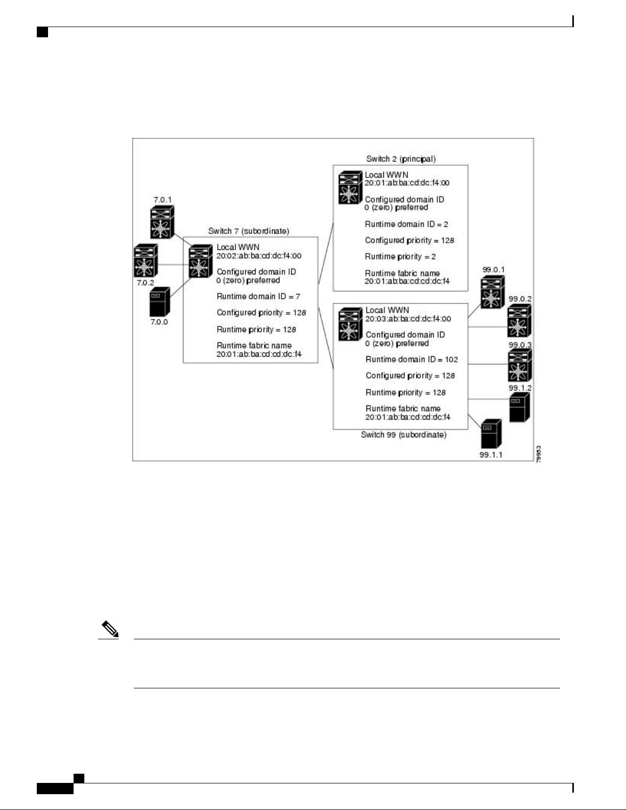
The 0 (zero) value can be configured only if you use the preferred option.Note
If you do not configure a domain ID, the local switch sends a random ID in its request. We recommend that
you use static domain IDs.
When a subordinate switch requests a domain, the following process takes place (see the figure below):
The local switch sends a configured domain ID request to the principal switch.
•
Cisco Nexus 6000 Series NX-OS SAN Switching Configuration Guide, Release 6.x
12 OL-27932-01
Page 33

Configuring Fibre Channel Domain Parameters
The principal switch assigns the requested domain ID if available. Otherwise, it assigns another available
•
domain ID.
Figure 2: Configuration Process Using the Preferred Option
Domain IDs
The operation of a subordinate switch changes based on three factors:
The allowed domain ID lists
•
The configured domain ID
•
The domain ID that the principal switch has assigned to the requesting switch
•
In specific situations, the changes are as follows:
When the received domain ID is not within the allowed list, the requested domain ID becomes the
•
runtime domain ID and all interfaces on that VSAN are isolated.
When the assigned and requested domain IDs are the same, the preferred and static options are not
•
relevant, and the assigned domain ID becomes the runtime domain ID.
When the assigned and requested domain IDs are different, the following cases apply:
•
If the configured type is static, the assigned domain ID is discarded, all local interfaces are isolated,
◦
and the local switch assigns itself the configured domain ID, which becomes the runtime domain
ID.
If the configured type is preferred, the local switch accepts the domain ID assigned by the principal
◦
switch and the assigned domain ID becomes the runtime domain ID.
Cisco Nexus 6000 Series NX-OS SAN Switching Configuration Guide, Release 6.x
OL-27932-01 13
Page 34

Domain IDs
Configuring Fibre Channel Domain Parameters
If you change the configured domain ID, the change is only accepted if the new domain ID is included in all
the allowed domain ID lists currently configured in the VSAN. Alternatively, you can also configure
zero-preferred domain ID.
Caution
You must enter the fcdomain restart command if you want to apply the configured domain changes to the
runtime domain.
Note
If you have configured an allow domain ID list, the domain IDs that you add must be in that range for the
VSAN.
Related Topics
Allowed Domain ID Lists, on page 15
Configuring Static or Preferred Domain IDs
You can specify a static or preferred domain ID.
Procedure
Step 1
Example:
switch# configure terminal
switch(config)#
Step 2
Step 3
Step 4
fcdomain domain domain-id static vsan
vsan-id
Example:
switch(config)# fcdomain domain 1
static vsan 3
no fcdomain domain domain-id static
vsan vsan-id
Example:
switch(config)# no fcdomain domain 1
static vsan 3
fcdomain domain domain-id preferred
vsan vsan-id
Example:
switch(config)# fcdomain domain 1
preferred vsan 5
PurposeCommand or Action
Enters global configuration mode.configure terminal
Configures the switch in the specified VSAN to accept
only a specific value and moves the local interfaces
in the specified VSAN to an isolated state if the
requested domain ID is not granted. The domain ID
range is 1 to 239. The VSAN ID range is 1 to 4093.
Resets the configured domain ID to factory defaults
in the specified VSAN. The configured domain ID
becomes 0 preferred.
Configures the switch in the specified VSAN to
request a preferred domain ID 3 and accepts any value
assigned by the principal switch. The domain ID range
is 1 to 239. The VSAN ID range is 1 to 4093.
Cisco Nexus 6000 Series NX-OS SAN Switching Configuration Guide, Release 6.x
14 OL-27932-01
Page 35

Configuring Fibre Channel Domain Parameters
Domain IDs
PurposeCommand or Action
Step 5
no fcdomain domain domain-id
preferred vsan vsan-id
Example:
switch(config)# no fcdomain domain 1
preferred vsan 5
Allowed Domain ID Lists
By default, the valid range for an assigned domain ID list is from 1 to 239. You can specify a list of ranges
to be in the allowed domain ID list and separate each range with a comma. The principal switch assigns domain
IDs that are available in the locally configured allowed domain list.
Use allowed domain ID lists to design your VSANs with nonoverlapping domain IDs. This helps you in the
future if you need to implement IVR without the NAT feature.
If you configure an allowed list on one switch in the fabric, we recommend that you configure the same list
in all other switches in the fabric to ensure consistency or use CFS to distribute the configuration.
Configuring Allowed Domain ID Lists
You can configure the allowed domain ID list.
Resets the configured domain ID to 0 (default) in the
specified VSAN. The configured domain ID becomes
0 preferred.
Procedure
Step 1
Step 2
Step 3
Example:
switch# configure terminal
switch(config)#
fcdomain allowed domain-id range vsan
vsan-id
Example:
switch(config)# fcdomain allowed 3 vsan
10
no fcdomain allowed domain-id range vsan
vsan-id
Example:
switch(config)# no fcdomain allowed 3
vsan 10
PurposeCommand or Action
Enters global configuration mode.configure terminal
Configures the list to allow switches with the
domain ID range in the specified VSAN. The
domain ID range is from 1 to 239. The VSAN
ID range is from 1 to 4093.
Reverts to the factory default of allowing domain
IDs from 1 through 239 in the specified VSAN.
Cisco Nexus 6000 Series NX-OS SAN Switching Configuration Guide, Release 6.x
OL-27932-01 15
Page 36

Domain IDs
CFS Distribution of Allowed Domain ID Lists
You can enable the distribution of the allowed domain ID list configuration information to all Cisco SAN
switches in the fabric using the Cisco Fabric Services (CFS) infrastructure. This feature allows you to
synchronize the configuration across the fabric from the console of a single switch. Because the same
configuration is distributed to the entire VSAN, you can avoid a possible misconfiguration and the possibility
that two switches in the same VSAN have configured incompatible allowed domains.
Use CFS to distribute the allowed domain ID list to ensure consistency in the allowed domain ID lists on all
switches in the VSAN.
We recommend configuring the allowed domain ID list and committing it on the principal switch.Note
For additional information, refer to Using Cisco Fabric Services in the System Management Configuration
Guide for your device.
Configuring Fibre Channel Domain Parameters
Enabling Distribution
You can enable (or disable) allowed domain ID list configuration distribution.
CFS distribution of allowed domain ID lists is disabled by default. You must enable distribution on all switches
to which you want to distribute the allowed domain ID lists.
Procedure
Step 1
Step 2
Step 3
Example:
switch# configure terminal
switch(config)#
fcdomain distribute
Example:
switch(config)# fcdomain distribute
no fcdomain distribute
Example:
switch(config)# no fcdomain distribute
PurposeCommand or Action
Enters global configuration mode.configure terminal
Enables domain configuration
distribution.
Disables (default) domain configuration
distribution.
Locking the Fabric
The first action that modifies the existing configuration creates the pending configuration and locks the feature
in the fabric. After you lock the fabric, the following conditions apply:
No other user can make any configuration changes to this feature.
•
Cisco Nexus 6000 Series NX-OS SAN Switching Configuration Guide, Release 6.x
16 OL-27932-01
Page 37

Configuring Fibre Channel Domain Parameters
A pending configuration is created by copying the active configuration. Subsequent modifications are
•
made to the pending configuration and remain there until you commit the changes to the active
configuration (and other switches in the fabric) or discard them.
Committing Changes
You can commit pending domain configuration changes and release the lock.
To apply the pending domain configuration changes to other SAN switches in the VSAN, you must commit
the changes. The pending configuration changes are distributed and, on a successful commit, the configuration
changes are applied to the active configuration in the SAN switches throughout the VSAN and the fabric lock
is released.
Procedure
Domain IDs
PurposeCommand or Action
Step 1
Step 2
Discarding Changes
You can discard pending domain configuration changes and release the lock.
At any time, you can discard the pending changes to the domain configuration and release the fabric lock. If
you discard (abort) the pending changes, the configuration remains unaffected and the lock is released.
Procedure
Step 1
Example:
switch# configure terminal
switch(config)#
fcdomain commit vsan vsan-id
Example:
switch(config)# fcdomain commit vsan 45
Enters global configuration mode.configure terminal
Commits the pending domain
configuration changes.
PurposeCommand or Action
Enters global configuration mode.configure terminal
Example:
switch# configure terminal
switch(config)#
Step 2
fcdomain abort vsan vsan-id
Discards the pending domain
configuration changes.
Example:
switch(config)# fcdomain abort vsan 30
Cisco Nexus 6000 Series NX-OS SAN Switching Configuration Guide, Release 6.x
OL-27932-01 17
Page 38

Domain IDs
Clearing a Fabric Lock
If you have performed a domain configuration task and have not released the lock by either committing or
discarding the changes, an administrator can release the lock from any switch in the fabric. If the administrator
performs this task, your pending changes are discarded and the fabric lock is released.
The pending changes are only available in the volatile directory and are discarded if the switch is restarted.
To release a fabric lock, enter the clear fcdomain session vsan command in EXEC mode using a login ID
that has administrative privileges:
switch# clear fcdomain session vsan 10
Displaying CFS Distribution Status
You can display the status of CFS distribution for allowed domain ID lists by using the show fcdomain status
command:
switch# show fcdomain status
CFS distribution is enabled
Configuring Fibre Channel Domain Parameters
Displaying Pending Changes
You can display the pending configuration changes by using the show fcdomain pending command:
switch# show fcdomain pending vsan 10
Pending Configured Allowed Domains
---------------------------------VSAN 10
Assigned or unallowed domain IDs: 1-9,24,100,231-239.
[User] configured allowed domain IDs: 10-230.
You can display the differences between the pending configuration and the current configuration by using
the show fcdomain pending-diff command:
switch# show fcdomain pending-diff vsan 10
Current Configured Allowed Domains
---------------------------------VSAN 10
Assigned or unallowed domain IDs: 24,100.
[User] configured allowed domain IDs: 1-239.
Pending Configured Allowed Domains
---------------------------------VSAN 10
Assigned or unallowed domain IDs: 1-9,24,100,231-239.
[User] configured allowed domain IDs: 10-230.
Displaying Session Status
You can display the status of the distribution session by using the show fcdomain session-status vsan
command:
switch# show fcdomain session-status vsan 1
Last Action: Distribution Enable
Result: Success
Cisco Nexus 6000 Series NX-OS SAN Switching Configuration Guide, Release 6.x
18 OL-27932-01
Page 39

Configuring Fibre Channel Domain Parameters
Contiguous Domain ID Assignments
By default, the contiguous domain assignment is disabled. When a subordinate switch requests the principal
switch for two or more domains and the domains are not contiguous, the following situations can occur:
If the contiguous domain assignment is enabled in the principal switch, the principal switch locates
•
contiguous domains and assigns them to the subordinate switches. If contiguous domains are not available,
the switch software rejects this request.
If the contiguous domain assignment is disabled in the principal switch, the principal switch assigns the
•
available domains to the subordinate switch.
Enabling Contiguous Domain ID Assignments
You can enable contiguous domains in a specific VSAN (or a range of VSANs).
Procedure
FC IDs
FC IDs
Step 1
Step 2
Step 3
Example:
switch# configure terminal
switch(config)#
fcdomain contiguous-allocation vsan vsan-id
- vsan-id
Example:
switch(config)# fcdomain
contiguous-allocation vsan 22-30
no fcdomain contiguous-allocation vsan
vsan-id
Example:
switch(config)# no fcdomain
contiguous-allocation vsan 7
PurposeCommand or Action
Enters global configuration mode.configure terminal
Enables the contiguous allocation option in the
specified VSAN range.
Note
The contiguous-allocation option takes
immediate effect at runtime. You do not
need to restart the fcdomain.
Disables the contiguous allocation option and
reverts it to the factory default in the specified
VSAN.
When an N port logs into a SAN switch, it is assigned an FC ID. By default, the persistent FC ID feature is
enabled. If this feature is disabled, the following situations can occur:
An N port logs into a SAN switch. The WWN of the requesting N port and the assigned FC ID are
•
retained and stored in a volatile cache. The contents of this volatile cache are not saved across reboots.
Cisco Nexus 6000 Series NX-OS SAN Switching Configuration Guide, Release 6.x
OL-27932-01 19
Page 40

FC IDs
•
•
•
Persistent FC IDs
When persistent FC IDs are enabled, the following occurs:
•
•
Configuring Fibre Channel Domain Parameters
The switch is designed to preserve the binding FC ID to the WWN on a best-effort basis. For example,
if one N port disconnects from the switch and its FC ID is requested by another device, this request is
granted and the WWN with the initial FC ID association is released.
The volatile cache stores up to 4000 entries of WWN to FC ID binding. If this cache is full, a new (more
recent) entry overwrites the oldest entry in the cache. In this case, the corresponding WWN to FC ID
association for the oldest entry is lost.
N ports receive the same FC IDs if disconnected and reconnected to any port within the same switch (as
long as it belongs to the same VSAN).
The current FC IDs in use in the fcdomain are saved across reboots.
The fcdomain automatically populates the database with dynamic entries that the switch has learned
about after a device (host or disk) is plugged into a port interface.
Note
If you connect to the switch from an AIX or HP-UX host, be sure to enable the persistent FC ID feature
in the VSAN that connects these hosts.
Note
When persistent FC IDs are enabled, FC IDs cannot be changed after a reboot. FC IDs are enabled by
default, but can be disabled for each VSAN.
A persistent FC ID assigned to an F port can be moved across interfaces and can continue to maintain the
same persistent FC ID.
Enabling the Persistent FC ID Feature
You can enable the persistent FC ID feature.
Procedure
Step 1
Example:
switch# configure terminal
switch(config)#
Step 2
fcdomain fcid persistent vsan vsan-id
Example:
switch(config)# fcdomain fcid persistent
vsan 78
PurposeCommand or Action
Enters global configuration mode.configure terminal
Activates (default) persistency of FC IDs
in the specified VSAN.
Cisco Nexus 6000 Series NX-OS SAN Switching Configuration Guide, Release 6.x
20 OL-27932-01
Page 41

Configuring Fibre Channel Domain Parameters
FC IDs
PurposeCommand or Action
Step 3
no fcdomain fcid persistent vsan vsan-id
Example:
switch(config)# no fcdomain fcid persistent
vsan 33
Persistent FC ID Configuration Guidelines
When the persistent FC ID feature is enabled, you can enter the persistent FC ID submode and add static or
dynamic entries in the FC ID database. By default, all added entries are static. Persistent FC IDs are configured
on a per-VSAN basis.
When manually configuring a persistent FC ID, follow these requirements:
Ensure that the persistent FC ID feature is enabled in the required VSAN.
•
Ensure that the required VSAN is an active VSAN. Persistent FC IDs can only be configured on active
•
VSANs.
Verify that the domain part of the FC ID is the same as the runtime domain ID in the required VSAN.
•
If the software detects a domain mismatch, the command is rejected.
Verify that the port field of the FC ID is 0 (zero) when configuring an area.
•
Disables the FC ID persistency feature in
the specified VSAN.
Configuring Persistent FC IDs
You can configure persistent FC IDs.
Procedure
Step 1
Example:
switch# configure terminal
switch(config)#
Step 2
Example:
switch(config)# fcdomain fcid database
Step 3
vsan vsan-id wwn 33:e8:00:05:30:00:16:df
fcid fcid
Example:
switch(config-fcid-db)# vsan 26 wwn
33:e8:00:05:30:00:16:df fcid 4
PurposeCommand or Action
Enters global configuration mode.configure terminal
Enters FC ID database configuration submode.fcdomain fcid database
Configures a device WWN
(33:e8:00:05:30:00:16:df) with the FC ID 0x070128
in the specified VSAN.
Cisco Nexus 6000 Series NX-OS SAN Switching Configuration Guide, Release 6.x
OL-27932-01 21
Page 42

FC IDs
PurposeCommand or Action
Note
Configuring Fibre Channel Domain Parameters
To avoid assigning a duplicate FC ID, use
the show fcdomain address-allocation
vsan command to display the FC IDs in
use.
Step 4
vsan vsan-id wwn 11:22:11:22:33:44:33:44
fcid fcid dynamic
Example:
switch(config-fcid-db)# vsan 13 wwn
11:22:11:22:33:44:33:44 fcid 6 dynamic
Step 5
vsan vsan-id wwn 11:22:11:22:33:44:33:44
fcid fcid area
Example:
switch(config-fcid-db)# vsan 88 wwn
11:22:11:22:33:44:33:44 fcid 4 area
Unique Area FC IDs for HBAs
Note
Read this section only if the Host Bus Adapter (HBA) port and the storage port are connected to the same
switch.
Some HBA ports require a different area ID than for the storage ports when they are both connected to the
same switch. For example, if the storage port FC ID is 0x6f7704, the area for this port is 77. In this case, the
HBA port’s area can be anything other than 77. The HBA port’s FC ID must be manually configured to be
different from the storage port’s FC ID.
Cisco SAN switches facilitate this requirement with the FC ID persistence feature. You can use this feature
to preassign an FC ID with a different area to either the storage port or the HBA port.
Configures a device WWN
(11:22:11:22:33:44:33:44) with the FC ID
0x070123 in the specified VSAN in dynamic mode.
Configures a device WWN
(11:22:11:22:33:44:33:44) with the FC IDs
0x070100 through 0x701FF in the specified VSAN.
Note
To secure the entire area for this fcdomain,
assign 00 as the last two characters of the
FC ID.
Configuring Unique Area FC IDs for an HBA
You can configure a different area ID for the HBA port.
The following task uses an example configuration with a switch domain of 111(6f hex). The server connects
to the switch over FCoE. The HBA port connects to interface vfc20 and the storage port connects to interface
fc2/3 on the same switch.
Procedure
Step 1
Cisco Nexus 6000 Series NX-OS SAN Switching Configuration Guide, Release 6.x
22 OL-27932-01
Obtain the port WWN (Port Name field) ID of the HBA using the show flogi database command.
switch# show flogi database
Page 43

Configuring Fibre Channel Domain Parameters
-----------------------------------------------------------------
INTERFACE VSAN FCID PORT NAME NODE NAME
------------------------------------------------------------------
vfc20 3 0x6f7703 50:05:08:b2:00:71:c8:c2 50:05:08:b2:00:71:c8:c0
vfc23 3 0x6f7704 50:06:0e:80:03:29:61:0f 50:06:0e:80:03:29:61:0f
Note
Both FC IDs in this setup have the same area 77
assignment.
Step 2
Step 3
Shut down the HBA interface in the SAN switch.
switch# configure terminal
switch(config)# interface vfc 20
switch(config-if)# shutdown
switch(config-if)# end
Verify that the FC ID feature is enabled using the show fcdomain vsan command.
switch# show fcdomain vsan 1
...
Local switch configuration information:
State: Enabled
FCID persistence: Disabled
If this feature is disabled, continue to the next step to enable the persistent FC ID.
If this feature is already enabled, skip to the following step.
FC IDs
Step 4
Step 5
Step 6
Step 7
Enable the persistent FC ID feature in the SAN switch.
switch# configure terminal
switch(config)# fcdomain fcid persistent vsan 1
switch(config)# end
Assign a new FC ID with a different area allocation. In this example, replace 77 with ee.
switch# configure terminal
switch(config)# fcdomain fcid database
switch(config-fcid-db)# vsan 3 wwn 50:05:08:b2:00:71:c8:c2
fcid 0x6fee00 area
Enable the HBA interface in the SAN switch.
switch# configure terminal
switch(config)# interface vfc 20
switch(config-if)# no shutdown
switch(config-if)# end
Verify the pWWN ID of the HBA by using the show flogi database command.
switch# show flogi database
------------------------------------------------------------------
INTERFACE VSAN FCID PORT NAME NODE NAME
------------------------------------------------------------------
vfc20 3 0x6fee00 50:05:08:b2:00:71:c8:c2 50:05:08:b2:00:71:c8:c0
vfc23 3 0x6f7704 50:06:0e:80:03:29:61:0f 50:06:0e:80:03:29:61:0f
Note
Both FC IDs now have different area
assignments.
Cisco Nexus 6000 Series NX-OS SAN Switching Configuration Guide, Release 6.x
OL-27932-01 23
Page 44

Verifying the fcdomain Configuration
Persistent FC ID Selective Purging
Persistent FC IDs can be purged selectively. Static entries and FC IDs currently in use cannot be deleted. The
table below identifies the FC ID entries that are deleted or retained when persistent FC IDs are purged.
Table 1: Purged FC IDs
Configuring Fibre Channel Domain Parameters
ActionPersistent Usage StatePersistent FC ID state
Not deletedIn useStatic
Not deletedNot in useStatic
Not deletedIn useDynamic
DeletedNot in useDynamic
Purging Persistent FC IDs
You can purge persistent FC IDs.
Procedure
Step 1
Step 2
purge fcdomain fcid vsan vsan-id
Example:
switch# purge fcdomain fcid vsan 667
purge fcdomain fcid vsan vsan-id - vsan-id
Example:
switch# purge fcdomain fcid vsan 50-100
Verifying the fcdomain Configuration
Note
If the fcdomain feature is disabled, the runtime fabric name in the display is the same as the configured
fabric name.
PurposeCommand or Action
Purges all dynamic and unused FC IDs in
the specified VSAN.
Purges dynamic and unused FC IDs in the
specified VSAN range.
This example shows how to display information about fcdomain configurations:
switch# show fcdomain vsan 2
Cisco Nexus 6000 Series NX-OS SAN Switching Configuration Guide, Release 6.x
24 OL-27932-01
Page 45

Configuring Fibre Channel Domain Parameters
Use the show fcdomain domain-list command to display the list of domain IDs of all switches belonging to
a specified VSAN. This list provides the WWN of the switches owning each domain ID. The next example
uses the following values:
A switch with WWN of 20:01:00:05:30:00:47:df is the principal switch and has domain 200.
•
A switch with WWN of 20:01:00:0d:ec:08:60:c1 is the local switch (the one where you typed the CLI
•
command to show the domain-list) and has domain 99.
The IVR manager obtained virtual domain 97 using 20:01:00:05:30:00:47:df as the WWN for a virtual
•
switch.
switch# show fcdomain domain-list vsan 76
Number of domains: 3
Domain ID WWN
--------- ----------------------0xc8(200) 20:01:00:05:30:00:47:df [Principal]
0x63(99) 20:01:00:0d:ec:08:60:c1 [Local]
0x61(97) 50:00:53:0f:ff:f0:10:06 [Virtual (IVR)]
Use the show fcdomain allowed vsan command to display the list of allowed domain IDs configured on this
switch..
switch# show fcdomain allowed vsan 1
Assigned or unallowed domain IDs: 1-96,100,111-239.
[Interoperability Mode 1] allowed domain IDs: 97-127.
[User] configured allowed domain IDs: 50-110.
Ensure that the requested domain ID passes the switch software checks, if interop 1 mode is required in this
switch.
The following example shows how to display all existing, persistent FC IDs for a specified VSAN. You can
also specify the unused option to view only persistent FC IDs that are still not in use.
switch# show fcdomain fcid persistent vsan 1000
The following example shows how to display frame and other fcdomain statistics for a specified VSAN or
SAN port channel:
switch# show fcdomain statistics vsan 1
VSAN Statistics
Number of Principal Switch Selections: 5
Number of times Local Switch was Principal: 0
Number of 'Build Fabric's: 3
Number of 'Fabric Reconfigurations': 0
The following example shows how to display FC ID allocation statistics including a list of assigned and free
FC IDs:
switch# show fcdomain address-allocation vsan 1
The following example shows how to display the valid address allocation cache. The cache is used by the
principal switch to reassign the FC IDs for a device (disk or host) that exited and reentered the fabric. In the
cache content, VSAN refers to the VSAN that contains the device, WWN refers to the device that owned the
FC IDs, and mask refers to a single or entire area of FC IDs.
switch# show fcdomain address-allocation cache
Default Settings for Fibre Channel Domains
Default Settings for Fibre Channel Domains
The following table lists the default settings for all fcdomain parameters.
Cisco Nexus 6000 Series NX-OS SAN Switching Configuration Guide, Release 6.x
OL-27932-01 25
Page 46

Default Settings for Fibre Channel Domains
Table 2: Default fcdomain Parameters
Configuring Fibre Channel Domain Parameters
DefaultParameters
Enabledfcdomain feature
0 (zero)Configured domain ID
PreferredConfigured domain
Disabledauto-reconfigure option
Disabledcontiguous-allocation option
128Priority
1 to 239Allowed list
20:01:00:05:30:00:28:dfFabric name
Disabledrcf-reject
EnabledPersistent FC ID
DisabledAllowed domain ID list configuration distribution
Cisco Nexus 6000 Series NX-OS SAN Switching Configuration Guide, Release 6.x
26 OL-27932-01
Page 47

Configuring N Port Virtualization
This chapter contains the following sections:
Configuring N Port Virtualization, page 27
•
Configuring N Port Virtualization
Information About NPV
NPV Overview
By default, Cisco Nexus devices switches operate in fabric mode. In this mode, the switch provides standard
Fibre Channel switching capability and features.
In fabric mode, each switch that joins a SAN is assigned a domain ID. Each SAN (or VSAN) supports a
maximum of 239 domain IDs, so the SAN has a limit of 239 switches. In a SAN topology with a large number
of edge switches, the SAN may need to grow beyond this limit. NPV alleviates the domain ID limit by sharing
the domain ID of the core switch among multiple edge switches.
In NPV mode, the edge switch relays all traffic from server-side ports to the core switch. The core switch
provides F port functionality (such as login and port security) and all the Fibre Channel switching capabilities.
The edge switch appears as a Fibre Channel host to the core switch and as a regular Fibre Channel switch to
its connected devices.
CHAPTER 3
Cisco Nexus 6000 Series NX-OS SAN Switching Configuration Guide, Release 6.x
OL-27932-01 27
Page 48

Information About NPV
NPV Mode
Configuring N Port Virtualization
The following figure shows an interface-level view of an NPV configuration.
Figure 3: NPV Interface Configuration
In NPV mode, the edge switch relays all traffic to the core switch, which provides the Fibre Channel switching
capabilities. The edge switch shares the domain ID of the core switch.
To convert a switch into NPV mode, you set the NPV feature to enabled. This configuration command
automatically triggers a switch reboot. You cannot configure NPV mode on a per-interface basis. NPV mode
applies to the entire switch.
In NPV mode, a subset of fabric mode CLI commands and functionality is supported. For example, commands
related to fabric login and name server registration are not required on the edge switch, because these functions
are provided in the core switch. To display the fabric login and name server registration databases, you must
enter the show flogi database and show fcns database commands on the core switch.
Server Interfaces
Server interfaces are F ports on the edge switch that connect to the servers. A server interface may support
multiple end devices by enabling the N port identifier virtualization (NPIV) feature. NPIV provides a means
to assign multiple FC IDs to a single N port, which allows the server to assign unique FC IDs to different
applications.
Note
To use NPIV, enable the NPIV feature and reinitialize the server interfaces that will support multiple
devices.
As the NPIV box has multiple FLOGIs from the NPV box, the disable-feature command is rejected.Note
In Cisco Nexus devices, server interfaces can be virtual Fibre Channel interfaces.
Related Topics
Configuring N Port Virtualization, on page 27
Cisco Nexus 6000 Series NX-OS SAN Switching Configuration Guide, Release 6.x
28 OL-27932-01
Page 49

Configuring N Port Virtualization
NP Uplinks
All interfaces from the edge switch to the core switch are configured as proxy N ports (NP ports).
An NP uplink is a connection from an NP port on the edge switch to an F port on the core switch. When an
NP uplink is established, the edge switch sends a fabric login message (FLOGI) to the core switch, and then
(if the FLOGI is successful) it registers itself with the name server on the core switch. Subsequent FLOGIs
from end devices connected to this NP uplink are forwarded as-is to the core switch.
In the switch CLI configuration commands and output displays, NP uplinks are called External Interfaces.Note
In Cisco Nexus devices, NP uplink interfaces are virtual Fibre Channel interfaces.
Related Topics
Fabric Login, on page 119
Information About NPV
FLOGI Operation
When an NP port becomes operational, the switch first logs itself in to the core switch by sending a FLOGI
request (using the port WWN of the NP port).
After completing the FLOGI request, the switch registers itself with the fabric name server on the core switch
(using the symbolic port name of the NP port and the IP address of the edge switch).
The following table identifies port and node names in the edge switch used in NPV mode.
Table 3: Edge Switch FLOGI Parameters
symbolic port name
Derived FromParameter
The fWWN of the NP port on the edge switch.pWWN
The VSAN-based sWWN of the edge switch.nWWN
The edge switch name and NP port interface string.
Note
If no switch name is available, the output
will read "switch." For example, switch: fc
1/5.
The IP address of the edge switch.IP address
The edge switch name.symbolic node name
We do not recommend using fWWN-based zoning on the edge switch for the following reasons:
Zoning is not enforced at the edge switch (rather, it is enforced on the core switch).
•
Multiple devices attached to an edge switch log in through the same F port on the core, so they cannot
•
be separated into different zones.
Cisco Nexus 6000 Series NX-OS SAN Switching Configuration Guide, Release 6.x
OL-27932-01 29
Page 50

NPV Guidelines and Limitations
The same device might log in using different fWWNs on the core switch (depending on the NPV link
•
it uses) and may need to be zoned using different fWWNs.
Related Topics
Information About Zones, on page 79
NPV Traffic Management Guidelines
When deploying NPV traffic management, follow these guidelines:
Use NPV traffic management only when automatic traffic engineering does not meet your network
•
requirements.
You do not need to configure traffic maps for all server interfaces. By default, NPV will use automatic
•
traffic management.
Configuring N Port Virtualization
NPV Guidelines and Limitations
When configuring NPV, note the following guidelines and limitations:
In-order data delivery is not required in NPV mode because the exchange between two end devices
•
always takes the same uplink from the edge switch to the core. Upstream of the edge switch, core switches
will enforce in-order delivery if configured.
You can configure zoning for end devices that are connected to edge switches using all available member
•
types on the core switch. For fWWN, sWWN, domain, or port-based zoning, use the fWWN, sWWN,
domain, or port of the core switch in the configuration commands.
Port tracking is not supported in NPV mode.
•
Port security is supported on the core switch for devices logged in through the NPV switch. Port security
•
is enabled on the core switch on a per-interface basis. To enable port security on the core switch for
devices that log in through an NPV switch, you must adhere to the following requirements:
The internal FLOGI must be in the port security database; in this way, the port on the core switch
◦
will allow communications and links.
All the end device pWWNs must also be in the port security database.
◦
Servers can be connected to the switch when in NPV mode.
•
When initiators and targets are assigned to the same border port (NP or NP-PO), then Cisco Nexus 5000
•
Series switches in NPIV mode do not support hairpinning.
Fibre Channel switching is not performed in the edge switch; all traffic is switched in the core switch.
•
NPV supports NPIV-capable servers. This capability is called nested NPIV.
•
Connecting two Cisco NPV switches together is not supported.
•
Only VF and VNP port types are supported in NPV mode.
•
For an NPV switch which is configured for trunking on any interface, or for a regular switch where the
•
f port-channel-trunk command is issued to enable the Trunking F Port Channels feature, follow these
configuration guidelines for reserved VSANs and isolated VSAN:
Cisco Nexus 6000 Series NX-OS SAN Switching Configuration Guide, Release 6.x
30 OL-27932-01
Page 51

Configuring N Port Virtualization
Configuring NPV
Enabling NPV
When you enable NPV, the system configuration is erased and the switch reboots.
Configuring NPV
If the trunk mode is enabled for any of the interfaces, or if the NP port channel is up, the reserved
•
VSANs range from 3840 to 4078, which are not available for user configuration.
The Exchange Virtual Fabric Protocol (EVFP) isolated VSAN is 4079, and it is not available for
•
user configuration.
Note
We recommend that you save your current configuration either in boot flash memory or to a TFTP server
before you enable NPV.
To enable NPV, perform this task:
Procedure
PurposeCommand or Action
Step 1
Step 2
switch(config)# npv enable
Enters configuration mode.switch# configure terminal
Enables NPV mode. The switch reboots, and it comes back up
in NPV mode.
Note
When the switch is reloaded in the NPV mode, only
the following configurations are saved:
switchname
•
management ip configuration and vrf
•
boot variable
•
username / password details
•
ntp configuration
•
callhome configuration
•
snmp-server details
•
feature fcoe
•
Step 3
enable
Cisco Nexus 6000 Series NX-OS SAN Switching Configuration Guide, Release 6.x
OL-27932-01 31
Disables NPV mode, which results in a reload of the switch.switch(config-npv)# no npv
Page 52

Configuring NPV
Configuring NPV Interfaces
After you enable NPV, you should configure the NP uplink interfaces and the server interfaces.
Configuring an NP Interface
After you enable NPV, you should configure the NP uplink interfaces and the server interfaces. To configure
an NP uplink interface, perform this task:
To configure a server interface, perform this task:
Procedure
Configuring N Port Virtualization
PurposeCommand or Action
Step 1
Step 2
Step 3
Step 4
Configuring a Server Interface
To configure a server interface, perform this task:
Procedure
Step 1
Step 2
Step 3
switch(config)# interface vfc vfc-id
switch(config)# interface vfc vfc-id
Enters global configuration mode.switch# configure terminal
Selects an interface that will be connected to
the core NPV switch.
Configures the interface as an NP port.switch(config-if)# switchport mode NP
Brings up the interface.switch(config-if)# no shutdown
PurposeCommand or Action
Enters global configuration mode.switch# configure terminal
Selects an interface that will be connected to
the core NPV switch.
Configures the interface as an F port.switch(config-if)# switchport mode F
Step 4
Brings up the interface.switch(config-if)# no shutdown
Configuring NPV Traffic Management
Configuring NPV Traffic Maps
An NPV traffic map associates one or more NP uplink interfaces with a server interface. The switch associates
the server interface with one of these NP uplinks.
Cisco Nexus 6000 Series NX-OS SAN Switching Configuration Guide, Release 6.x
32 OL-27932-01
Page 53

Configuring N Port Virtualization
Verifying NPV
Note
If a server interface is already mapped to an NP uplink, you should include this mapping in the traffic
map configuration.
To configure a traffic map, perform this task:
Procedure
Step 1
Step 2
switch(config)# npv traffic-map
server-interface vfc vfc-id
external-interface vfc vfc-id
Step 3
switch(config)# no npv traffic-map
server-interface vfc vfc-id
external-interface vfc vfc-id
Enabling Disruptive Load Balancing
If you configure additional NP uplinks, you can enable the disruptive load-balancing feature to distribute the
server traffic load evenly among all the NP uplinks.
To enable disruptive load balancing, perform this task:
PurposeCommand or Action
Enters global configuration mode.switch# configure terminal
Configures a mapping between a server interface
(or range of server interfaces) and an NP uplink
interface (or range of NP uplink interfaces).
Removes the mapping between the specified
server interfaces and NP uplink interfaces.
Verifying NPV
Procedure
Step 1
Step 2
switch(config)# npv auto-load-balance
disruptive
Step 3
switch (config)# no npv auto-load-balance
disruptive
To display information about NPV, perform the following task:
PurposeCommand or Action
Enters configuration mode on the NPV.switch# configure terminal
Enables disruptive load balancing on the
switch.
Disables disruptive load balancing on the
switch.
Cisco Nexus 6000 Series NX-OS SAN Switching Configuration Guide, Release 6.x
OL-27932-01 33
Page 54

Verifying NPV
Configuring N Port Virtualization
Procedure
PurposeCommand or Action
Step 1
Verifying NPV Examples
To display a list of devices on a server interface and their assigned NP uplinks, enter the show npv flogi-table
command on the Cisco Nexus device:
switch# show npv flogi-table
-------------------------------------------------------------------------------SERVER EXTERNAL
INTERFACE VSAN FCID PORT NAME NODE NAME INTERFACE
--------------------------------------------------------------------------------vfc31 1 0xee0008 10:00:00:00:c9:60:e4:9a 20:00:00:00:c9:60:e4:9a vfc21
vfc31 1 0xee0009 20:00:00:00:0a:00:00:01 20:00:00:00:c9:60:e4:9a vfc22
vfc31 1 0xee000a 20:00:00:00:0a:00:00:02 20:00:00:00:c9:60:e4:9a vfc23
vfc31 1 0xee000b 33:33:33:33:33:33:33:33 20:00:00:00:c9:60:e4:9a vfc24
Total number of flogi = 4
For each server interface, the External Interface value displays the assigned NP uplink.Note
To display the status of the server interfaces and the NP uplink interfaces, enter the show npv status command:
switch# show npv status
npiv is enabled
External Interfaces:
====================
Interface: vfc21, VSAN: 1, FCID: 0x1c0000, State: Up
Interface: vfc22, VSAN: 1, FCID: 0x040000, State: Up
Interface: vfc23, VSAN: 1, FCID: 0x260000, State: Up
Interface: vfc24, VSAN: 1, FCID: 0x1a0000, State: Up
Number of External Interfaces: 4
Server Interfaces:
==================
Interface: vfc31, VSAN: 1, NPIV: No, State: Up
Number of Server Interfaces: 1
Displays the NPV configuration.switch# show npv flogi-table [all]
Note
To view fcns database entries for NPV edge switches, you must enter the show fcns database command
on the core switch.
To view all the NPV edge switches, enter the show fcns database command on the core switch:
core-switch# show fcns database
For additional details (such as IP addresses, switch names, interface names) about the NPV edge switches
that you see in the show fcns database output, enter the show fcns database detail command on the core
switch:
core-switch# show fcns database detail
Cisco Nexus 6000 Series NX-OS SAN Switching Configuration Guide, Release 6.x
34 OL-27932-01
Page 55

Configuring N Port Virtualization
Verifying NPV Traffic Management
To display the NPV traffic map, enter the show npv traffic-map command.
switch# show npv traffic-map
NPV Traffic Map Information:
---------------------------------------Server-If External-If(s)
---------------------------------------vfc13 vfc110,vfc111
vfc15 vfc11,vfc12
----------------------------------------
To display the NPV internal traffic details, enter the show npv internal info traffic-map command.
To display the disruptive load-balancing status, enter the show npv status command:
switch# show npv status
npiv is enabled
disruptive load balancing is enabled
External Interfaces:
====================
Interface: vfc21, VSAN: 2, FCID: 0x1c0000, State: Up
...
Verifying NPV
Cisco Nexus 6000 Series NX-OS SAN Switching Configuration Guide, Release 6.x
OL-27932-01 35
Page 56

Verifying NPV
Configuring N Port Virtualization
Cisco Nexus 6000 Series NX-OS SAN Switching Configuration Guide, Release 6.x
36 OL-27932-01
Page 57

Configuring FCoE NPV
This chapter contains the following sections:
Information About FCoE NPV, page 37
•
FCoE NPV Model, page 39
•
Mapping Requirements, page 40
•
Port Requirements, page 41
•
NPV Features, page 41
•
vPC Topologies, page 42
•
Supported and Unsupported Topologies, page 43
•
Guidelines and Limitations, page 47
•
FCoE NPV Configuration Limits, page 47
•
Default Settings, page 48
•
CHAPTER 4
Enabling FCoE and Enabling NPV, page 49
•
Enabling FCoE NPV, page 49
•
Configuring NPV Ports for FCoE NPV, page 50
•
Verifying FCoE NPV Configuration, page 50
•
Configuration Examples for FCoE NPV, page 51
•
Information About FCoE NPV
FCoE NPV is supported on the Cisco Nexus devices. The FCoE NPV feature is an enhanced form of FIP
snooping that provides a secure method to connect FCoE-capable hosts to an FCoE-capable FCoE forwarder
(FCF) switch. The FCoE NPV feature provides the following benefits:
FCoE NPV does not have the management and troubleshooting issues that are inherent to managing
•
hosts remotely at the FCF.
Cisco Nexus 6000 Series NX-OS SAN Switching Configuration Guide, Release 6.x
OL-27932-01 37
Page 58

Information About FCoE NPV
•
•
You can enable FCoE NPV by choosing one of the following methods:
• Enable FCoE and then enable NPV—This method requires that you enable FCoE first using the
• Enable FCoE NPV—When you enable FCoE NPV using the feature fcoe-npv command, the mode
Configuring FCoE NPV
FCoE NPV implements FIP snooping as an extension to the NPV function while retaining the
traffic-engineering, vsan-management, administration and trouble-shooting aspects of NPV.
FCoE NPV and NPV together allow communication through FC and FCoE ports at the same time. This
provides a smooth transition when moving from FC to FCoE topologies.
feature fcoe command and then you enable NPV by using the feature npv command. When FCoE is
enabled, the default mode of operation is FC switching and when you enable NPV, the mode changes
to NPV mode. Switching to NPV mode automatically performs a write erase and reloads the system.
After the reload, the system comes up in NPV mode. To exit NPV mode and return to FC switching
mode, enter the no feature npv command. Exiting NPV mode also triggers a write erase and a switch
reload. This method requires the Storage Protocols Services Package (FC_FEATURES_PKG) license
.
changes to NPV. When you use this method, a write erase and reload does not occur. This method
requires a separate license package (N6K-FNPV-SSK9). This license is also included in the Storage
Protocol Services License.
ReloadWrite EraseLicenseMethod
Enable FCoE and then
Enable NPV
Services Package
YesYesStorage Protocols
(FC_FEATURES_PKG)
NoNo(N6K-FNPV-SSK9)Enable FCoE NPV
Interoperability with FCoE-Capable Switches
The Cisco Nexus device interoperates with the following FCoE-capable switches:
Cisco MDS 9000 Series Multilayer switches enabled to perform FCF functions (EthNPV and VE)
•
Cisco Nexus 7000 Series switches enabled to perform FCF functions (EthNPV and VE)
•
Cisco Nexus 4000 Series switches enabled for FIP Snooping
•
For detailed information about switch interoperability, see the Cisco Data Center Interoperability Support
Matrix.
Licensing
The following table shows the licensing requirements for FCoE NPV:
Cisco Nexus 6000 Series NX-OS SAN Switching Configuration Guide, Release 6.x
38 OL-27932-01
Page 59

Configuring FCoE NPV
FCoE NPV Model
License RequirementProduct
NX-OS
FCoE NPV Model
The following figure shows the FCoE NPV bridge connecting hosts and FCFs. From a control plane perspective,
FCoE NPV performs proxy functions towards the FCF and the hosts in order to load balance logins from the
FCoE NPV requires a separate license
(FCOE_NPV_PKG). The FCoE NPV license is also
included in the Storage Protocol Services License.
FCoE and NPV require the Storage Protocols Services
Package (FC_FEATURES_PKG).
For detailed information about features that require
licensing and Cisco NX-OS license installation, see
the Cisco NX-OS Licensing Guide.
For information about troubleshooting licensing
issues, see the Troubleshooting Guide for your device.
Cisco Nexus 6000 Series NX-OS SAN Switching Configuration Guide, Release 6.x
OL-27932-01 39
Page 60

Mapping Requirements
hosts evenly across the available FCF uplink ports. An FCoE NPV bridge is VSAN-aware and capable of
assigning VSANs to the hosts.
Figure 4: FCoE NPV Model
Configuring FCoE NPV
Mapping Requirements
VSANs and VLAN-VSAN Mapping
VSANs from the hosts must be created and for each VSAN, a dedicated VLAN must also be created and
mapped. The mapped VLAN is used to carry FIP and FCoE traffic for the corresponding VSAN. The
VLAN-VSAN mapping must be configured consistently in the entire fabric. The Cisco Nexus device supports
32 VSANs.
FC Mapping
The FC-MAP value associated with a SAN fabric must be configured on the FCoE NPV bridge which helps
the FCoE NPV bridge isolate misconnections to FCFs in other fabrics.
Cisco Nexus 6000 Series NX-OS SAN Switching Configuration Guide, Release 6.x
40 OL-27932-01
Page 61

Configuring FCoE NPV
Port Requirements
VF Ports
For each host directly connected over Ethernet interfaces on the FCoE NPV bridge, a virtual Fibre Channel
(vFC) interface must be created and bound to the Ethernet interface. By default, the vFC interface is configured
in the F mode (VF port).
The VF port must be configured with the following parameters:
A VF port must be bound to a VLAN trunk Ethernet interface or a port-channel interface. The FCoE
•
VLAN must not be configured as the native VLAN on the Ethernet interface.
A port VSAN must be configured for the VF port.
•
The administrative state must be up.
•
VNP Ports
Connectivity from an FCoE NPV bridge to the FCF is only supported over point-to-point links. These links
can be individual Ethernet interfaces or members of an Ethernet port channel interface. For each FCF connected
Ethernet interfaces, a vFC interface must be created and bound to the Ethernet interface. These vFC interfaces
must be configured as VNP ports. On the VNP port, an FCoE NPV bridge emulates an FCoE-capable host
with multiple enodes, each with a unique enode MAC address. A VNP port interface binding to MAC address
is not supported. By default, the VNP port is enabled in trunk mode. Multiple VSANs can be configured on
the VNP port. The FCoE VLANs that correspond to the VNP port VSANs must be configured on the bound
Ethernet interface.
Port Requirements
Note
The spanning-tree protocol (STP) is automatically disabled in the FCoE VLAN on the interfaces that the
VNP port are bound to.
NPV Features
The following NPV features apply for the FCoE NPV feature:
Automatic Traffic Mapping
•
Static Traffic Mapping
•
Disruptive Load Balancing
•
FCoE Forwarding in the FCoE NPV Bridge
•
FCoE frames received over VNP ports are forwarded only if the L2_DA matches one of the FCoE MAC
•
addresses assigned to hosts on the VF ports otherwise they’re discarded.
Cisco Nexus 6000 Series NX-OS SAN Switching Configuration Guide, Release 6.x
OL-27932-01 41
Page 62

vPC Topologies
vPC Topologies
When VNP ports are configured vPC topologies between an FCoE NPV bridge and an FCF, the following
limitations apply:
vPC spanning multiple FCFs in the same SAN fabric is not supported.
•
For LAN traffic, dedicated links must be used for FCoE VLANs between the FCoE NPV bridge and
•
the FCF connected over a vPC.
FCoE VLANs must not be configured on the inter-switch vPC interfaces.
•
VF port binding to a vPC member port is not supported for an inter-switch vPC.
•
Figure 5: VNP Ports in an Inter-Switch vPC Topology
Configuring FCoE NPV
Cisco Nexus 6000 Series NX-OS SAN Switching Configuration Guide, Release 6.x
42 OL-27932-01
Page 63

Configuring FCoE NPV
Supported and Unsupported Topologies
FCoE NPV supports the following topologies:
Figure 6: Cisco Nexus Device As An FCoE NPV Device Connected to a Cisco Nexus Device Over A Non- vPC Port Channel
Supported and Unsupported Topologies
Figure 7: Cisco Nexus Device As An FCoE NPV Device Connected Over a vPC To Another Cisco Nexus Device
Figure 8: Cisco Nexus Device With A 10GB Fabric Extender As An FCoE NPV Device Connected to a Cisco Nexus Device
Over A Non- vPC Port Channel
Cisco Nexus 6000 Series NX-OS SAN Switching Configuration Guide, Release 6.x
OL-27932-01 43
Page 64

Supported and Unsupported Topologies
Configuring FCoE NPV
Figure 9: Cisco Nexus Device With A 10GB Fabric Extender as an FCoE NPV Device Connected Over a vPC to Another
Cisco Nexus Device
Figure 10: Cisco Nexus Device As An FCoE NPV Bridge Connecting to a FIP Snooping Bridge
Cisco Nexus 6000 Series NX-OS SAN Switching Configuration Guide, Release 6.x
44 OL-27932-01
Page 65

Configuring FCoE NPV
Supported and Unsupported Topologies
Cisco Nexus 6000 Series NX-OS SAN Switching Configuration Guide, Release 6.x
OL-27932-01 45
Page 66

Supported and Unsupported Topologies
Unsupported Topologies
FCoE NPV does not support the following topologies:
Figure 11: 10GB Fabric Extender Connecting To The Same FCoE NPV Bridge Over Multiple VF Ports
Configuring FCoE NPV
Figure 12: Cisco Nexus Device As An FCoE NPV Bridge Connecting To A FIP Snooping Bridge Or Another FCoE NPV Bridge
Figure 13: VF Port Trunk To Hosts In FCoE NPV Mode
Cisco Nexus 6000 Series NX-OS SAN Switching Configuration Guide, Release 6.x
46 OL-27932-01
Page 67

Configuring FCoE NPV
Guidelines and Limitations
Figure 14: Cisco Nexus Device As An FCoE NPV Bridge Connecting to an FCoE NPV Bridge
Guidelines and Limitations
The FCoE NPV feature has the following guidelines and limitations:
When FCoE NPV mode is configured on a switch, the FCoE feature cannot be enabled. A warning is
•
displayed to reload the system first in order to enable FCoE.
You can not perform an in-service software downgrade (ISSD) to Cisco NX-OS Release 5.0(3)N1(1)
•
or an earlier release if FCoE NPV is enabled and if VNP ports are configured.
A warning is displayed if an ISSD is performed to Cisco NX-OS Release 5.0(3)N1(1) or an earlier
•
release when FCoE NPV is enabled but VNP ports are not configured.
Before performing an ISSU on an FCoE NPV bridge, use the disable-fka command to disable the timeout
•
value check (FKA check) on the core switch.
FCoE NPV Configuration Limits
The following table lists the FCoE configuration limits over Ethernet, Ethernet port channel, and virtual
Ethernet interfaces.
Cisco Nexus 6000 Series NX-OS SAN Switching Configuration Guide, Release 6.x
OL-27932-01 47
Page 68

Default Settings
Configuring FCoE NPV
Table 4: VNP Port Configuration Limits
Cisco Nexus 6000 SeriesInterface Type
interface
channel interface
(vEth) interface
The configuration limits guidelines are as follows:
The number of VF port and VN port interfaces that can be supported between a given FCF and an FCoE
•
NPV bridge also depends on the FCF to MAC advertising capability of the FCF:
If an FCF advertises the same FCF-MAC address over all of its interfaces, then the FCoE NPV
◦
bridge can connect to it over one VNP Port. In this scenario, we recommend that one port channel
interface be used for redundancy.
If an FCF advertises multiple FCF-MAC addresses, then the limits in the previous table apply. For
◦
additional information, see the best practices recommendations for the FCF switch.
The total number of supported VSANs is 31 (excluding the EVFP VSAN).
•
Cisco Nexus 2000 Series (10G
interfaces)
Not Supported4 VNP portsVNP port bound to Ethernet
Not Supported2 VNP portsVNP port bound to Ethernet port
Not SupportedNot SupportedVNP port bound to virtual Ethernet
The total number of supported FCIDs is 2048.
•
Default Settings
The following table lists the default settings for FCoE NPV parameters.
Table 5: Default FCoE NPV Parameters
DefaultParameters
DisabledFCoE NPV
DisabledFCoE
DisabledNPV
DisabledVNP port
DisabledFIP Keep Alive (FKA)
Cisco Nexus 6000 Series NX-OS SAN Switching Configuration Guide, Release 6.x
48 OL-27932-01
Page 69

Configuring FCoE NPV
Enabling FCoE and Enabling NPV
You can enable FCoE first and then enable NPV. This method requires the full Storage Services License. A
write erase reload occurs when this method is used. This method allows both FCoE and FC upstream and host
NPV connections. You must also configure class-fcoe in all QoS policy types.
1
Enable FCoE.
switch# configure terminal
switch(config)# feature fcoe
FC license checked out successfully
fc_plugin extracted successfully
FC plugin loaded successfully
FCoE manager enabled successfully
FC enabled on all modules successfully
Warning: Ensure class-fcoe is included in qos policy-maps of all types
2
Enable NPV.
switch# configure terminal
switch(config)# feature npv
Enabling FCoE and Enabling NPV
Enabling FCoE NPV
You can enable FCoE NPV using the feature fcoe-npv command. We recommend this method in topologies
that include all FCoE connections. A write erase reload does not occur when you use this method and a storage
service license is not required. Enabling FCoE NPV using the feature fcoe-npv command requires an installed
FCOE_NPV_PKG license.
Before You Begin
FCoE NPV has the following prerequisites:
Ensure that the correct licenses are installed.
•
Configure the VNP ports.
•
Procedure
Step 1
Step 2
Step 3
Step 4
switch(config)# copy running-config
startup-config
PurposeCommand or Action
Enters global configuration mode.switch# configure terminal
Enables FCoE NPV.feature fcoe-npv
Exits configuration mode.exit
(Optional)
Saves the change persistently through reboots and
restarts by copying the running configuration to the
startup configuration.
Cisco Nexus 6000 Series NX-OS SAN Switching Configuration Guide, Release 6.x
OL-27932-01 49
Page 70

Configuring NPV Ports for FCoE NPV
This example shows how to enable FCoE NPV using the feature fcoe-npv command.
switch# configure terminal
switch(config)# feature fcoe-npv
FCoE NPV license checked out successfully
fc_plugin extracted successfully
FC plugin loaded successfully
FCoE manager enabled successfully
FCoE NPV enabled on all modules successfully
This example shows how to enable FCoE NPV using the feature fcoe and feature npv commands.
switch# configure terminal
switch(config)# feature fcoe
switch(config)# feature npv
Configuring NPV Ports for FCoE NPV
You can configure NVP port for FCoE NPV.
1
Create a vFC port.
switch# config t
switch(config)# interface vfc 20
switch(config-if)#
2
Bind the vFC to an Ethernet port.
switch(config-if)# bind interface ethernet 1/20
switch(config-if)#
3
Set the port mode to NP.
switch(config-if)# switchport mode NP
switch(config-if)#
4
Bring up the port:
switch(config-if)# interface vfc 20no shutdown
switch(config-if)#
Configuring FCoE NPV
Verifying FCoE NPV Configuration
To display FCoE NPV configuration information, perform one of the following tasks:
PurposeCommand
Displays information about the FCoE database.show fcoe database
show interface Ethernet x/y fcoe
show interface vfc x
Cisco Nexus 6000 Series NX-OS SAN Switching Configuration Guide, Release 6.x
50 OL-27932-01
Displays FCoE information for a specified Ethernet
interface including the following:
FCF or associated enode MAC address
•
Status
•
Associated VFC information
•
Displays information about the specified vFC
interface including attributes and status.
Page 71

Configuring FCoE NPV
Configuration Examples for FCoE NPV
PurposeCommand
show npv status
Displays the status of the NPV configuration
including information about VNP ports.
Displays the impact of FCoE NPV on an ISSU.show fcoe-npv issu-impact
show running-config fcoe_mgr
Displays the running configuration information about
FCoE.
show startup-config fcoe_mgr
Displays the startup configuration information about
FCoE.
Displays troubleshooting information about FCoE.show tech-support fcoe
show npv flogi-table
Displays information about N port virtualization
(NPV) fabric login (FLOGI) session
show fcoe
Displays the status of Fibre Channel over Ethernet
(FCoE) configurations.
For detailed information about the fields in the output from these commands, refer to the command reference
for your device.
Configuration Examples for FCoE NPV
This example shows how to enable FCoE NPV, LACP, QoS for no drop queuing, and VLAN/VSAN mapping:
switch# config t
switch(config)# feature fcoe-npv
FCoE NPV license checked out successfully
fc_plugin extracted successfully
FC plugin loaded successfully
FCoE manager enabled successfully
FCoE NPV enabled on all modules successfully
switch(config)# feature lacp
switch# config t
switch(config)# system qos
switch(config-sys-qos)# service-policy type qos input fcoe-default-in-policy
switch(config-sys-qos)# service-policy type queuing input fcoe-default-in-policy
switch(config-sys-qos)# service-policy type queuing output fcoe-default-out-policy
switch(config-sys-qos)# service-policy type network-qos fcoe-default-nq-policy
switch(config)# vsan database
switch(config-vsan-db)# vsan 50-51
switch(config-vsan-db)# vlan 50
switch(config-vlan)# fcoe vsan 50
switch(config-vlan)# vlan 51
switch(config-vlan)# fcoe vsan 51
This example shows a summary of the interface configuration information for trunked NP
ports:
switch# show interface brief | grep TNP
vfc25 400 NP on trunking swl TNP 2 --
Cisco Nexus 6000 Series NX-OS SAN Switching Configuration Guide, Release 6.x
OL-27932-01 51
Page 72

Configuration Examples for FCoE NPV
vfc26 400 NP on trunking swl TNP 2 -vfc130 1 NP on trunking -- TNP auto -switch#
This example shows the running configuration information about FCoE:
switch# show running-config fcoe_mgr
!Command: show running-config fcoe_mgr
!Time: Wed Jan 20 21:59:39 2013
version 6.0(2)N1(1)
interface vfc1
bind interface Ethernet1/19
interface vfc2
bind interface Ethernet1/2
interface vfc90
bind interface Ethernet1/9
interface vfc100
bind interface Ethernet1/10
interface vfc110
bind interface port-channel110
interface vfc111
bind interface Ethernet1/11
interface vfc120
bind interface port-channel120
interface vfc130
bind interface port-channel130
interface vfc177
bind interface Ethernet1/7
fcoe fka-adv-period 16
Configuring FCoE NPV
This example shows the FCoE VLAN to VSAN mappings:
switch# show vlan fcoe
Original VLAN ID Translated VSAN ID Association State
---------------- ------------------ -----------------
400 400 Operational
20 20 Operational
100 100 Operational
500 500 Operational
200 200 Operational
300 300 Operational
This example shows the information about the vFC 130 interface including attributes and status:
switch# show interface vfc 130
vfc130 is trunking (Not all VSANs UP on the trunk)
Bound interface is port-channel130
Hardware is Virtual Fibre Channel
Port WWN is 20:81:00:05:9b:74:bd:bf
Admin port mode is NP, trunk mode is on
snmp link state traps are enabled
Port mode is TNP
Port vsan is 1
Trunk vsans (admin allowed and active) (1,20,100,200,300,400,500)
Trunk vsans (up) (500)
Trunk vsans (isolated) ()
Trunk vsans (initializing) (1,20,100,200,300,400)
1 minute input rate 0 bits/sec, 0 bytes/sec, 0 frames/sec
1 minute output rate 0 bits/sec, 0 bytes/sec, 0 frames/sec
15 frames input, 2276 bytes
Cisco Nexus 6000 Series NX-OS SAN Switching Configuration Guide, Release 6.x
52 OL-27932-01
Page 73

Configuring FCoE NPV
Configuration Examples for FCoE NPV
0 discards, 0 errors
7 frames output, 1004 bytes
0 discards, 0 errors
last clearing of "show interface" counters Tue May 31 20:56:41 2011
Interface last changed at Wed Jun 1 21:53:08 2011
This example shows the information about the vFC 1 interface including attributes and status:
switch# show interface vfc 1
vfc1 is trunking (Not all VSANs UP on the trunk)
Bound interface is Ethernet1/19
Hardware is Virtual Fibre Channel
Port WWN is 20:00:00:05:9b:74:bd:bf
Admin port mode is F, trunk mode is on
snmp link state traps are enabled
Port mode is TF
Port vsan is 20
Trunk vsans (admin allowed and active) (1,20,100,200,300,400,500)
Trunk vsans (up) (20)
Trunk vsans (isolated) ()
Trunk vsans (initializing) (1,100,200,300,400,500)
1 minute input rate 0 bits/sec, 0 bytes/sec, 0 frames/sec
1 minute output rate 0 bits/sec, 0 bytes/sec, 0 frames/sec
355278397 frames input, 573433988904 bytes
0 discards, 0 errors
391579316 frames output, 572319570200 bytes
0 discards, 0 errors
last clearing of "show interface" counters Tue May 31 20:56:41 2011
Interface last changed at Wed Jun 1 20:25:36 2011
This example shows the information about the NPV FLOGI session:
switch# show npv flogi-table
-------------------------------------------------------------------------------SERVER EXTERNAL
INTERFACE VSAN FCID PORT NAME NODE NAME INTERFACE
-------------------------------------------------------------------------------vfc1 20 0x670000 21:01:00:1b:32:2a:e5:b8 20:01:00:1b:32:2a:e5:b8 vfc26
Total number of flogi = 1.
This example shows the status of the NPV configuration including information about VNP ports:
switch# show npv status
npiv is enabled
disruptive load balancing is disabled
External Interfaces:
====================
Interface: vfc25, State: Trunking
VSAN: 1, State: Up
VSAN: 200, State: Up
VSAN: 400, State: Up
VSAN: 20, State: Up
VSAN: 100, State: Up
VSAN: 300, State: Up
VSAN: 500, State: Up, FCID: 0xa10000
Interface: vfc26, State: Trunking
VSAN: 1, State: Up
VSAN: 200, State: Up
VSAN: 400, State: Up
VSAN: 20, State: Up
VSAN: 100, State: Up
VSAN: 300, State: Up
VSAN: 500, State: Up, FCID: 0xa10001
Interface: vfc90, State: Down
Interface: vfc100, State: Down
Interface: vfc110, State: Down
Interface: vfc111, State: Down
Cisco Nexus 6000 Series NX-OS SAN Switching Configuration Guide, Release 6.x
OL-27932-01 53
Page 74

Configuration Examples for FCoE NPV
Interface: vfc120, State: Down
Interface: vfc130, State: Trunking
VSAN: 1, State: Waiting For VSAN Up
VSAN: 200, State: Up
VSAN: 400, State: Up
VSAN: 100, State: Up
VSAN: 300, State: Up
VSAN: 500, State: Up, FCID: 0xa10002
Number of External Interfaces: 8
Server Interfaces:
==================
Interface: vfc1, VSAN: 20, State: Up
Interface: vfc2, VSAN: 4094, State: Down
Interface: vfc3, VSAN: 4094, State: Down
Interface: vfc5000, VSAN: 4094, State: Down
Interface: vfc6000, VSAN: 4094, State: Down
Interface: vfc7000, VSAN: 4094, State: Down
Interface: vfc8090, VSAN: 4094, State: Down
Interface: vfc8191, VSAN: 4094, State: Down
Number of Server Interfaces: 8
This example shows the running configuration of port channel 130:
switch# show running-config interface port-channel 130
Configuring FCoE NPV
!Command: show running-config interface port-channel130
!Time: Wed Jan 30 22:01:05 2013
version 6.0(2)N1(1)
interface port-channel130
switchport mode trunk
switchport trunk native vlan 2
no negotiate auto
This example shows the impact of FCoE NPV on an ISSU:
switch# show fcoe-npv issu-impact
show fcoe-npv issu-impact
-------------------------
Please make sure to enable "disable-fka" on all logged in VFCs
Please increase the FKA duration to 60 seconds on FCF
Active VNP ports with no disable-fka set
----------------------------------------
vfc90
vfc100
vfc110
vfc111
vfc120
vfc130
ISSU downgrade not supported as feature fcoe-npv is enabled
switch#
Cisco Nexus 6000 Series NX-OS SAN Switching Configuration Guide, Release 6.x
54 OL-27932-01
Page 75

Configuring VSAN Trunking
This chapter describes how to configure VSAN trunking.
This chapter includes the following sections:
Configuring VSAN Trunking, page 55
•
Configuring VSAN Trunking
Information About VSAN Trunking
VSAN trunking enable interconnected ports to transmit and receive frames in more than one VSAN. Trunking
is supported on E ports and F ports.
VSAN trunking is supported on virtual Fibre Channel interfaces.
The VSAN trunking feature includes the following restrictions:
CHAPTER 5
Trunking configurations are applicable only to E ports. If trunk mode is enabled in an E port and that
•
port becomes operational as a trunking E port, it is referred to as a TE port.
The trunk-allowed VSANs configured for TE ports are used by the trunking protocol to determine the
•
allowed-active VSANs in which frames can be received or transmitted.
If a trunking-enabled E port is connected to a third-party switch, the trunking protocol ensures seamless
•
operation as an E port.
Cisco Nexus 6000 Series NX-OS SAN Switching Configuration Guide, Release 6.x
OL-27932-01 55
Page 76

Information About VSAN Trunking
VSAN Trunking Mismatches
If you misconfigure VSAN configurations across E ports, issues can occur such as the merging of traffic in
two VSANs (causing both VSANs to mismatch). The VSAN trunking protocol validates the VSAN interfaces
at both ends of an ISL to avoid merging VSANs (see the following figure).
Figure 15: VSAN Mismatch
In this example, the trunking protocol detects potential VSAN merging and isolates the ports involved.
The trunking protocol cannot detect merging of VSANs when a third-party switch is placed in between two
Cisco SAN switches (see the following figure).
Configuring VSAN Trunking
Figure 16: Third-Party Switch VSAN Mismatch
VSAN 2 and VSAN 3 are effectively merged with overlapping entries in the name server and the zone
applications. Cisco MDS 9000 Fabric Manager helps detect such topologies.
VSAN Trunking Protocol
The trunking protocol is important for E-port and TE-port operations. It supports the following capabilities:
Dynamic negotiation of operational trunk mode.
•
Selection of a common set of trunk-allowed VSANs.
•
Detection of a VSAN mismatch across an ISL.
•
By default, the VSAN trunking protocol is enabled. If the trunking protocol is disabled on a switch, no port
on that switch can apply new trunk configurations. Existing trunk configurations are not affected: the TE port
continues to function in trunk mode but only supports traffic in VSANs that it negotiated with previously
(when the trunking protocol was enabled). Other switches that are directly connected to this switch are similarly
affected on the connected interfaces. If you need to merge traffic from different port VSANs across a
nontrunking ISL, disable the trunking protocol.
Cisco Nexus 6000 Series NX-OS SAN Switching Configuration Guide, Release 6.x
56 OL-27932-01
Page 77

Configuring VSAN Trunking
Configuring VSAN Trunking
Guidelines and Limitations
When configuring VSAN trunking, note the following guidelines:
We recommend that both ends of a VSAN trunking ISL belong to the same port VSAN. On platforms
•
or fabric switches where the port VSANs are different, one end returns an error, and the other is not
connected.
To avoid inconsistent configurations, disable all E ports with a shutdown command before enabling or
•
disabling the VSAN trunking protocol.
Enabling or Disabling the VSAN Trunking Protocol
You can enable or disable the VSAN trunking protocol.
Configuring VSAN Trunking
Trunk Mode
Procedure
PurposeCommand or Action
Step 1
Example:
switch# configure terminal
switch(config)#
Step 2
Example:
switch(config)# no trunk protocol enable
Step 3
Example:
switch(config)# trunk protocol enable
By default, trunk mode is enabled in all Fibre Channel interfaces. However, trunk mode configuration takes
effect only in E-port mode. You can configure trunk mode as on (enabled), off (disabled), or auto (automatic).
The default trunk mode is on. The trunk mode configurations at the two ends of the link determine the trunking
state of the link and the port modes at both ends (see the following table).
Enters global configuration mode.configure terminal
Disables the trunking protocol.no trunk protocol enable
Enables trunking protocol (default).trunk protocol enable
Cisco Nexus 6000 Series NX-OS SAN Switching Configuration Guide, Release 6.x
OL-27932-01 57
Page 78

Configuring VSAN Trunking
Table 6: Trunk Mode Status Between Switches
Mode
Configuration
The preferred configuration on the Cisco SAN switches is that one side of the trunk is set to auto and the other
is set to on.
Configuring VSAN Trunking
Resulting State and Port ModeYour Trunk
Port ModeTrunking StateSwitch 2Switch 1
TE portTrunking (EISL)Auto or onOn
E portNo trunking (ISL)Auto, on, or offOff
E portNo trunking (ISL)AutoAuto
Note
When connected to a third-party switch, the trunk mode configuration has no effect. The Inter-Switch
Link (ISL) is always in a trunking disabled state.
Configuring Trunk Mode
You can configure trunk mode.
Procedure
Step 1
Step 2
Step 3
Step 4
Example:
switch# configure terminal
switch(config)#
switch(config)# interface vfc vfc-id
interface vfc vfc-id
Example:
switch(config)# interface vfc 15
switchport trunk mode on
Example:
switch(config-if)# switchport trunk
mode on
PurposeCommand or Action
Enters global configuration mode.configure terminal
Selects an interface that will be connected to the
core NPV switch.
Configures the specified Fibre Channel or virtual
Fibre Channel interface.
Enables (default) the trunk mode for the specified
interface.
Cisco Nexus 6000 Series NX-OS SAN Switching Configuration Guide, Release 6.x
58 OL-27932-01
Page 79

Configuring VSAN Trunking
Configuring VSAN Trunking
PurposeCommand or Action
Step 5
switchport trunk mode off
Disables the trunk mode for the specified
interface.
Step 6
Example:
switch(config-if)# switchport trunk
mode off
switchport trunk mode auto
Note
Configures the trunk mode to auto mode, which
Trunk mode cannot be turned off for
virtual Fibre Channel interfaces.
provides automatic sensing for the interface.
Example:
switch(config-if)# switchport trunk
mode auto
EXAMPLES
This example shows how to configure a vFC interface in trunk mode:
switch# configure terminal
switch#(config)# vfc 200
switch(config-if)# switchport trunk mode on
This example shows the output for the vFC interface 200 in trunk mode:
switch(config-if)# show interface vfc200
vfc200 is trunking (Not all VSANs UP on the trunk)
Bound interface is Ethernet1/3
Hardware is Virtual Fibre Channel
Port WWN is 20:c7:00:0d:ec:f2:08:ff
Peer port WWN is 00:00:00:00:00:00:00:00
Admin port mode is E, trunk mode is on
snmp link state traps are enabled
Port mode is TE
Port vsan is 1
Trunk vsans (admin allowed and active) (1-6,10,22)
Trunk vsans (up) ()
Trunk vsans (isolated) ()
Trunk vsans (initializing) (1-6,10,22)
5 minute input rate 0 bits/sec, 0 bytes/sec, 0 frames/sec
5 minute output rate 0 bits/sec, 0 bytes/sec, 0 frames/sec
0 frames input, 0 bytes
0 discards, 0 errors
0 frames output, 0 bytes
0 discards, 0 errors
last clearing of "show interface" counters never
Interface last changed at Mon Jan 18 10:01:27 2010
Trunk-Allowed VSAN Lists
Each Fibre Channel interface has an associated trunk-allowed VSAN list. In TE-port mode, frames are
transmitted and received in one or more VSANs specified in this list. By default, the complete VSAN range
(1 through 4093) is included in the trunk-allowed list.
The common set of VSANs that are configured and active in the switch are included in the trunk-allowed
VSAN list for an interface, and they are called allowed-active VSANs. The trunking protocol uses the list of
allowed-active VSANs at the two ends of an ISL to determine the list of operational VSANs in which traffic
is allowed.
Cisco Nexus 6000 Series NX-OS SAN Switching Configuration Guide, Release 6.x
OL-27932-01 59
Page 80

Configuring VSAN Trunking
In the following figure, switch 1 has VSANs 1 through 5, switch 2 has VSANs 1 through 3, and switch 3 has
VSANs 1, 2, 4, and 5 with a default configuration of trunk-allowed VSANs. All VSANs configured in all
three switches are allowed-active. However, only the common set of allowed-active VSANs at the ends of
the ISL become operational as shown in below.
Figure 17: Default Allowed-Active VSAN Configuration
Configuring VSAN Trunking
You can configure a selected set of VSANs (from the allowed-active list) to control access to the VSANs
specified in a trunking ISL.
Using the figure above as an example, you can configure the list of allowed VSANs on a per-interface basis
(see the following figure). For example, if VSANs 2 and 4 are removed from the allowed VSAN list of ISLs
connecting to switch 1, the operational allowed list of VSANs for each ISL would be as follows:
The ISL between switch 1 and switch 2 includes VSAN 1 and VSAN 3.
•
The ISL between switch 2 and switch 3 includes VSAN 1 and VSAN 2.
•
The ISL between switch 3 and switch 1 includes VSAN 1, 2, and 5.
•
Cisco Nexus 6000 Series NX-OS SAN Switching Configuration Guide, Release 6.x
60 OL-27932-01
Page 81

Configuring VSAN Trunking
VSAN 2 can only be routed from switch 1 through switch 3 to switch 2.
Figure 18: Operational and Allowed VSAN Configuration
Configuring VSAN Trunking
Configuring an Allowed-Active List of VSANs
You can configure an allowed-active list of VSANs for an interface.
Procedure
Step 1
Example:
switch# configure terminal
switch(config)#
Step 2
Step 3
interface vfc vfc-id
Example:
switch(config)# interface vfc 4
switchport trunk allowed vsan vsan-id - vsan-id
Example:
switch(config-if)# switchport trunk allowed
vsan 35-55
PurposeCommand or Action
Enters global configuration mode.configure terminal
Configures the specified interface.
Changes the allowed list for the
specified VSAN range.
Cisco Nexus 6000 Series NX-OS SAN Switching Configuration Guide, Release 6.x
OL-27932-01 61
Page 82

Displaying VSAN Trunking Information
Configuring VSAN Trunking
PurposeCommand or Action
Step 4
switchport trunk allowed vsan add vsan-id
Example:
switch(config-if)# switchport trunk allowed
vsan add 40
Step 5
no switchport trunk allowed vsan vsan-id - vsan-id
Example:
switch(config-if)# no switchport trunk allowed
vsan 61-65
Step 6
no switchport trunk allowed vsan add vsan-id
Example:
switch(config-if)# no switchport trunk allowed
vsan add 40
Displaying VSAN Trunking Information
The show interface command is invoked from the EXEC mode and displays VSAN trunking configurations
for a TE port. Without any arguments, this command displays the information for all of the configured interfaces
in the switch.
The following example shows how to display the trunk mode of a Fibre Channel interface:
switch# show interface vfc33
vfc33 is up
Hardware is Fibre Channel, SFP is short wave laser w/o OFC (SN)
Port WWN is 20:83:00:0d:ec:6d:78:40
Peer port WWN is 20:0c:00:0d:ec:0d:d0:00
Admin port mode is auto, trunk mode is on
...
The following example shows how to display the trunk protocol of a Fibre Channel interface:
switch# show trunk protocol
Trunk protocol is enabled
The following example shows how to display the VSAN information for all trunk interfaces:
switch# show interface trunk vsan 1-1000
vfc31 is not trunking
...
vfc311 is trunking
Belongs to san-port-channel 6
Vsan 1 is up, FCID is 0xef0000
Vsan 2 is up, FCID is 0xef0000
...
san-port-channel 6 is trunking
Vsan 1 is up, FCID is 0xef0000
Vsan 2 is up, FCID is 0xef0000
Expands the specified VSAN to the
new allowed list.
Deletes the specified VSAN range.
Deletes the expanded allowed list.
Default Settings for VSAN Trunks
The following table lists the default settings for VSAN trunking parameters.
Cisco Nexus 6000 Series NX-OS SAN Switching Configuration Guide, Release 6.x
62 OL-27932-01
Page 83

Configuring VSAN Trunking
Table 7: Default VSAN Trunk Configuration Parameters
Default Settings for VSAN Trunks
DefaultParameters
OnSwitch port trunk mode
1 to 4093 user-defined VSAN IDsAllowed VSAN list
EnabledTrunking protocol
Cisco Nexus 6000 Series NX-OS SAN Switching Configuration Guide, Release 6.x
OL-27932-01 63
Page 84

Default Settings for VSAN Trunks
Configuring VSAN Trunking
Cisco Nexus 6000 Series NX-OS SAN Switching Configuration Guide, Release 6.x
64 OL-27932-01
Page 85

Configuring and Managing VSANs
This chapter describes how to configure and manage VSANs.
This chapter includes the following sections:
Configuring and Managing VSANs, page 65
•
Configuring and Managing VSANs
You can achieve higher security and greater stability in Fibre Channel fabrics by using virtual SANs (VSANs).
VSANs provide isolation among devices that are physically connected to the same fabric. With VSANs you
can create multiple logical SANs over a common physical infrastructure. Each VSAN can contain up to 239
switches and has an independent address space that allows identical Fibre Channel IDs (FC IDs) to be used
simultaneously in different VSANs.
CHAPTER 6
Information About VSANs
A VSAN is a virtual storage area network (SAN). A SAN is a dedicated network that interconnects hosts and
storage devices primarily to exchange SCSI traffic. In SANs you use the physical links to make these
interconnections. A set of protocols run over the SAN to handle routing, naming, and zoning. You can design
multiple SANs with different topologies.
You can achieve higher security and greater stability in Fibre Channel fabrics by using virtual SANs (VSANs).
VSANs provide isolation among devices that are physically connected to the same fabric. With VSANs you
can create multiple logical SANs over a common physical infrastructure. Each VSAN can contain up to 239
switches and has an independent address space that allows identical Fibre Channel IDs (FC IDs) to be used
simultaneously in different VSANs.
VSAN Topologies
A VSAN has the following additional features:
Multiple VSANs can share the same physical topology.
•
The same Fibre Channel IDs (FC IDs) can be assigned to a host in another VSAN, which increases
•
VSAN scalability.
Cisco Nexus 6000 Series NX-OS SAN Switching Configuration Guide, Release 6.x
OL-27932-01 65
Page 86

Information About VSANs
The following figure shows a fabric with three switches, one on each floor. The geographic location of the
switches and the attached devices is independent of their segmentation into logical VSANs. No communication
between VSANs is possible. Within each VSAN, all members can talk to one another.
Figure 19: Logical VSAN Segmentation
Configuring and Managing VSANs
Every instance of a VSAN runs all required protocols such as FSPF, domain manager, and zoning.
•
Fabric-related configurations in one VSAN do not affect the associated traffic in another VSAN.
•
Events causing traffic disruptions in one VSAN are contained within that VSAN and are not propagated
•
to other VSANs.
The application servers or storage arrays can be connected to the switch using Fibre Channel or virtual Fibre
Channel interfaces. A VSAN can include a mixture of Fibre Channel and virtual Fibre Channel interfaces.
Cisco Nexus 6000 Series NX-OS SAN Switching Configuration Guide, Release 6.x
66 OL-27932-01
Page 87

Configuring and Managing VSANs
The following figure shows a physical Fibre Channel switching infrastructure with two defined VSANs:
VSAN 2 (dashed) and VSAN 7 (solid). VSAN 2 includes hosts H1 and H2, application servers AS2 and AS3,
and storage arrays SA1 and SA4. VSAN 7 connects H3, AS1, SA2, and SA3.
Figure 20: Example of Two VSANs
Information About VSANs
The four switches in this network are interconnected by VSAN trunk links that carry both VSAN 2 and VSAN
7 traffic. You can configure a different inter-switch topology for each VSAN. In the preceding figure, the
inter-switch topology is identical for VSAN 2 and VSAN 7.
Without VSANs, a network administrator would need separate switches and links for separate SANs. By
enabling VSANs, the same switches and links might be shared by multiple VSANs. VSANs allow SANs to
be built on port granularity instead of switch granularity. The preceding figure illustrates that a VSAN is a
group of hosts or storage devices that communicate with each other using a virtual topology defined on the
physical SAN.
The criteria for creating such groups differ based on the VSAN topology:
VSANs can separate traffic based on the following requirements:
•
Different customers in storage provider data centers
◦
Production or test in an enterprise network
◦
Low and high security requirements
◦
Backup traffic on separate VSANs
◦
Replicating data from user traffic
◦
Cisco Nexus 6000 Series NX-OS SAN Switching Configuration Guide, Release 6.x
OL-27932-01 67
Page 88

Information About VSANs
VSANs can meet the needs of a particular department or application.
•
VSAN Advantages
VSANs offer the following advantages:
• Traffic isolation—Traffic is contained within VSAN boundaries and devices reside only in one VSAN
ensuring absolute separation between user groups, if desired.
• Scalability—VSANs are overlaid on top of a single physical fabric. The ability to create several logical
VSAN layers increases the scalability of the SAN.
• Per VSAN fabric services—Replication of fabric services on a per VSAN basis provides increased
scalability and availability.
• Redundancy—Several VSANs created on the same physical SAN ensure redundancy. If one VSAN
fails, redundant protection (to another VSAN in the same physical SAN) is configured using a backup
path between the host and the device.
• Ease of configuration—Users can be added, moved, or changed between VSANs without changing the
physical structure of a SAN. Moving a device from one VSAN to another only requires configuration
at the port level, not at a physical level.
Configuring and Managing VSANs
Up to 256 VSANs can be configured in a switch. Of these, one is a default VSAN (VSAN 1), and another is
an isolated VSAN (VSAN 4094). User-specified VSAN IDs range from 2 to 4093.
VSANs Versus Zones
Zones are always contained within a VSAN. You can define multiple zones in a VSAN.
Because two VSANs are equivalent to two unconnected SANs, zone A on VSAN 1 is different and separate
from zone A in VSAN 2. The following table lists the differences between VSANs and zones.
Table 8: VSAN and Zone Comparison
VSANs equal SANs with routing, naming, and zoning
protocols.
to F ports.
An HBA or a storage device can belong only to a
single VSAN (the VSAN associated with the F port).
Zone CharacteristicVSAN Characteristic
Routing, naming, and zoning protocols are not
available on a per-zone basis.
Zones limit unicast traffic.VSANs limit unicast, multicast, and broadcast traffic.
Membership is typically defined by the pWWN.Membership is typically defined using the VSAN ID
An HBA or storage device can belong to multiple
zones.
VSANs enforce membership at each E port, source
port, and destination port.
Cisco Nexus 6000 Series NX-OS SAN Switching Configuration Guide, Release 6.x
68 OL-27932-01
Zones enforce membership only at the source and
destination ports.
Page 89

Configuring and Managing VSANs
Guidelines and Limitations for VSANs
Zone CharacteristicVSAN Characteristic
VSANs are defined for larger environments (storage
service providers).
Zones are defined for a set of initiators and targets
not visible outside the zone.
Zones are configured at the fabric edge.VSANs encompass the entire fabric.
The following figure shows the possible relationships between VSANs and zones. In VSAN 2, three zones
are defined: zone A, zone B, and zone C. Zone C overlaps both zone A and zone B as permitted by Fibre
Channel standards. In VSAN 7, two zones are defined: zone A and zone D. No zone crosses the VSAN
boundary. Zone A defined in VSAN 2 is different and separate from zone A defined in VSAN 7.
Figure 21: VSANS with Zoning
Guidelines and Limitations for VSANs
VSANs have the following configuration guidelines and limitations:
• VSAN ID—The VSAN ID identifies the VSAN as the default VSAN (VSAN 1), user-defined VSANs
(VSAN 2 to 4093), and the isolated VSAN (VSAN 4094).
• State—The administrative state of a VSAN can be configured to an active (default) or suspended state.
Once VSANs are created, they may exist in various conditions or states.
The active state of a VSAN indicates that the VSAN is configured and enabled. By enabling a
◦
VSAN, you activate the services for that VSAN.
Cisco Nexus 6000 Series NX-OS SAN Switching Configuration Guide, Release 6.x
OL-27932-01 69
Page 90

Guidelines and Limitations for VSANs
The suspended state of a VSAN indicates that the VSAN is configured but not enabled. If a port
◦
is configured in this VSAN, it is disabled. Use this state to deactivate a VSAN without losing the
VSAN’s configuration. All ports in a suspended VSAN are disabled. By suspending a VSAN, you
can preconfigure all the VSAN parameters for the whole fabric and activate the VSAN immediately.
• VSAN name—This text string identifies the VSAN for management purposes. The name can be from
1 to 32 characters long and it must be unique across all VSANs. By default, the VSAN name is a
concatenation of VSAN and a four-digit string representing the VSAN ID. For example, the default
name for VSAN 3 is VSAN0003.
A VSAN name must be unique.Note
• Load-balancing attributes—These attributes indicate the use of the source-destination ID (src-dst-id) or
the originator exchange OX ID (src-dst-ox-id, the default) for load-balancing path selection.
A VSAN is in the operational state if the VSAN is active and at least one port is up. This state indicates
•
that traffic can pass through this VSAN. This state cannot be configured.
Configuring and Managing VSANs
You can create only 14 VSANs in N5672UP-16G, including the default VSAN 1.
•
For an NPV switch which is configured for trunking on any interface, or for a regular switch where the
•
f port-channel-trunk command is issued to enable the Trunking F Port Channels feature, follow these
configuration guidelines for reserved VSANs and isolated VSAN:
If the trunk mode is enabled for any of the interfaces, or if the NP port channel is up, the reserved
•
VSANs range from 3840 to 4078, which are not available for user configuration.
The Exchange Virtual Fabric Protocol (EVFP) isolated VSAN is 4079, and it is not available for
•
user configuration.
About VSAN Creation
A VSAN is in the operational state if the VSAN is active and at least one port is up. This state indicates that
traffic can pass through this VSAN. This state cannot be configured.
Creating VSANs Statically
You cannot configure any application-specific parameters for a VSAN before creating the VSAN.
Procedure
PurposeCommand or Action
Step 1
Example:
switch# configure terminal
switch(config)#
Cisco Nexus 6000 Series NX-OS SAN Switching Configuration Guide, Release 6.x
70 OL-27932-01
Enters global configuration mode.configure terminal
Page 91

Configuring and Managing VSANs
Guidelines and Limitations for VSANs
PurposeCommand or Action
Step 2
Step 3
Step 4
Step 5
Step 6
Step 7
vsan database
Example:
switch(config)# vsan database
vsan vsan-id
Example:
switch(config-vsan-db)# vsan 360
vsan vsan-id name name
Example:
switch(config-vsan-db)# vsan 360 name
test
vsan vsan-id suspend
Example:
switch(config-vsan-db)# vsan 470 suspend
switch(config-vsan-db)# no vsan vsan-id
suspend
Example:
switch(config-vsan-db)# no vsan 470
suspend
Configures the database for a VSAN.
Application specific VSAN parameters
cannot be configured from this prompt.
Creates a VSAN with the specified ID if that
VSAN does not exist already.
Updates the VSAN with the assigned name.
Suspends the selected VSAN.
Negates the suspend command issued in the
previous step.
Returns you to EXEC mode.switch(config-vsan-db)# end
Port VSAN Membership
Port VSAN membership on the switch is assigned on a port-by-port basis. By default each port belongs to
the default VSAN. You can assign VSAN membership to ports using one of two methods:
• Statically—Assigning VSANs to ports.
• Dynamically—Assigning VSANs based on the device WWN. This method is referred to as dynamic
port VSAN membership (DPVM).Cisco Nexus devices do not support DPVM.
VSAN trunking ports have an associated list of VSANs that are part of an allowed list.
Related Topics
Assigning Static Port VSAN Membership, on page 72
Configuring VSAN Trunking, on page 55
Example:
switch(config-vsan-db)# end
Cisco Nexus 6000 Series NX-OS SAN Switching Configuration Guide, Release 6.x
OL-27932-01 71
Page 92

Guidelines and Limitations for VSANs
Assigning Static Port VSAN Membership
You can statically assign VSAN membership for an interface port.
Procedure
Configuring and Managing VSANs
PurposeCommand or Action
Step 1
Step 2
Step 3
Step 4
Step 5
Example:
switch# configure terminal
switch(config)#
Example:
switch(config)# vsan database
switch(config-vsan-db)#
vsan vsan-id
Example:
switch(config-vsan-db)# vsan 50
switch(config-vsan-db)# vsan vsan-id
interface vfc vfc-id
switch(config-vsan-db)# vsan vsan-id vfc
vfc-id
Enters global configuration mode.configure terminal
Configures the database for a VSAN.vsan database
Creates a VSAN with the specified ID if that VSAN
does not exist already.
Assigns the membership of the specified interface
to the VSAN.
Updates the membership information of the interface
to reflect the changed VSAN.
Note
To remove the VSAN membership of a FC
or vFC interface, assign the VSAN
membership of that interface to another
VSAN. Cisco recommends that you assign
it to VSAN 1.
Displaying VSAN Static Membership
To display the VSAN static membership information, use the show vsan membership command.
The following example displays membership information for the specified VSAN:
switch # show vsan 1 membership
vsan 1 interfaces:
Interface information is not displayed if interfaces are not configured on this VSAN.Note
Cisco Nexus 6000 Series NX-OS SAN Switching Configuration Guide, Release 6.x
72 OL-27932-01
vfc21 vfc22 vfc23 vfc24
san-port-channel 3 vfc1/1
Page 93

Configuring and Managing VSANs
The following example displays membership information for all VSANs:
switch # show vsan membership
vsan 1 interfaces:
vsan 2 interfaces:
vsan 7 interfaces:
vsan 100 interfaces:
vsan 4094(isolated vsan) interfaces:
The following example displays static membership information for the specified interface:
switch # show vsan membership interface vfc21
vfc21
Default VSANs
The factory settings for Cisco SAN switches have only the default VSAN 1 enabled. We recommend that you
do not use VSAN 1 as your production environment VSAN. If no VSANs are configured, all devices in the
fabric are considered part of the default VSAN. By default, all ports are assigned to the default VSAN.
Guidelines and Limitations for VSANs
vfc21 vfc22 vfc23 vfc24
san-port-channel 3 vfc31
vfc23 vfc41
vsan:1
allowed list:1-4093
Note
VSAN 1 cannot be deleted, but it can be suspended.
Up to 256 VSANs can be configured in a switch. Of these, one is a default VSAN (VSAN 1), and another
is an isolated VSAN (VSAN 4094). User-specified VSAN IDs range from 2 to 4093.
Isolated VSANs
VSAN 4094 is an isolated VSAN. When a VSAN is deleted, all nontrunking ports are transferred to the
isolated VSAN to avoid an implicit transfer of ports to the default VSAN or to another configured VSAN.
This action ensures that all ports in the deleted VSAN become isolated (disabled).
When you configure a port in VSAN 4094 or move a port to VSAN 4094, that port is immediately isolated.Note
Do not use an isolated VSAN to configure ports.Caution
Note
Up to 256 VSANs can be configured in a switch. Of these, one is a default VSAN (VSAN 1), and another
is an isolated VSAN (VSAN 4094). User-specified VSAN IDs range from 2 to 4093.
Displaying Isolated VSAN Membership
The show vsan 4094 membership command displays all ports associated with the isolated VSAN.
Cisco Nexus 6000 Series NX-OS SAN Switching Configuration Guide, Release 6.x
OL-27932-01 73
Page 94

Guidelines and Limitations for VSANs
Operational State of a VSAN
A VSAN is in the operational state if the VSAN is active and at least one port is up. This state indicates that
traffic can pass through this VSAN. This state cannot be configured.
Static VSAN Deletion
When an active VSAN is deleted, all of its attributes are removed from the running configuration. VSAN-related
information is maintained by the system software as follows:
VSAN attributes and port membership details are maintained by the VSAN manager. This feature is
•
affected when you delete a VSAN from the configuration. When a VSAN is deleted, all the ports in that
VSAN are made inactive and the ports are moved to the isolated VSAN. If the same VSAN is recreated,
the ports do not automatically get assigned to that VSAN. You must explicitly reconfigure the port
VSAN membership (see the figure below).
Figure 22: VSAN Port Membership Details
Configuring and Managing VSANs
VSAN-based runtime (name server), zoning, and configuration (static routes) information is removed
•
when the VSAN is deleted.
Configured VSAN interface information is removed when the VSAN is deleted.
•
The allowed VSAN list is not affected when a VSAN is deleted.Note
Any commands for a nonconfigured VSAN are rejected. For example, if VSAN 10 is not configured in the
system, a command request to move a port to VSAN 10 is rejected.
Related Topics
Configuring VSAN Trunking, on page 55
Cisco Nexus 6000 Series NX-OS SAN Switching Configuration Guide, Release 6.x
74 OL-27932-01
Page 95

Configuring and Managing VSANs
Deleting Static VSANs
You can delete a VSAN and its various attributes.
Procedure
Guidelines and Limitations for VSANs
PurposeCommand or Action
Step 1
Step 2
Step 3
Step 4
Step 5
Example:
switch# configure terminal
switch(config)#
Example:
switch(config)# vsan database
switch(config-vsan-db)#
vsan vsan-id
Example:
switch(config-vsan-db)# vsan 2
switch(config-vsan-db)# no vsanvsan-id
Example:
switch(config-vsan-db)# no vsan 5
Example:
switch(config-vsan-db)# end
Enters global configuration mode.configure terminal
Configures the VSAN database.vsan database
Places you in VSAN configuration
mode.
Deletes VSAN 5 from the database and
switch.
Places you in EXEC mode.switch(config-vsan-db)# end
About Load Balancing
Load-balancing attributes indicate the use of the source-destination ID (src-dst-id) or the originator exchange
OX ID (src-dst-ox-id, the default) for load-balancing path selection.
Configuring Load Balancing
You can configure load balancing on an existing VSAN.
Load-balancing attributes indicate the use of the source-destination ID (src-dst-id) or the originator exchange
OX ID (src-dst-ox-id, the default) for load-balancing path selection.
Cisco Nexus 6000 Series NX-OS SAN Switching Configuration Guide, Release 6.x
OL-27932-01 75
Page 96

Guidelines and Limitations for VSANs
Procedure
Configuring and Managing VSANs
PurposeCommand or Action
Step 1
Step 2
Step 3
Step 4
Step 5
Step 6
Step 7
Example:
switch# configure terminal
switch(config)#
Example:
switch(config)# vsan database
switch(config-vsan-db)#
vsan vsan-id
Example:
switch(config-vsan-db)# vsan 15
vsan vsan-id loadbalancing src-dst-id
Example:
switch(config-vsan-db)# vsan 15
loadbalancing src-dst-id
no vsan vsan-id loadbalancing src-dst-id
Example:
switch(config-vsan-db)# no vsan 15
loadbalancing src-dst-id
vsan vsan-id loadbalancing src-dst-ox-id
Example:
switch(config-vsan-db)# vsan 15
loadbalancing src-dst-ox-id
vsan vsan-id suspend
Enters global configuration mode.configure terminal
Enters VSAN database configuration submodevsan database
Specifies an existing VSAN.
Enables the load-balancing guarantee for the
selected VSAN and directs the switch to use
the source and destination ID for its path
selection process.
Negates the command entered in the previous
step and reverts to the default values of the
load-balancing parameters.
Changes the path selection setting to use the
source ID, the destination ID, and the OX ID
(default).
Suspends the selected VSAN.
Example:
switch(config-vsan-db)# vsan 23 suspend
Step 8
no vsan vsan-id suspend
Negates the suspend command entered in the
previous step.
Example:
switch(config-vsan-db)# no vsan 23
suspend
Step 9
Returns you to EXEC mode.end
Example:
switch(config-vsan-db)# end
Cisco Nexus 6000 Series NX-OS SAN Switching Configuration Guide, Release 6.x
76 OL-27932-01
Page 97

Configuring and Managing VSANs
Interop Mode
Interoperability enables the products of multiple vendors to connect with each other. Fibre Channel standards
guide vendors to create common external Fibre Channel interfaces.
Related Topics
Switch Interoperability
Displaying the Static VSAN Configuration
The following example shows how to display information about a specific VSAN:
switch# show vsan 100
The following example shows how to display VSAN usage:
switch# show vsan usage
4 vsan configured
configured vsans:1-4
vsans available for configuration:5-4093
The following example shows how to display all VSANs:
switch# show vsan
Displaying the Static VSAN Configuration
Default Settings for VSANs
The following table lists the default settings for all configured VSANs.
Table 9: Default VSAN Parameters
Name
DefaultParameters
VSAN 1.Default VSAN
Active state.State
Concatenation of VSAN and a four-digit string
representing the VSAN ID. For example, VSAN 3 is
VSAN0003.
OX ID (src-dst-ox-id).Load-balancing attribute
Cisco Nexus 6000 Series NX-OS SAN Switching Configuration Guide, Release 6.x
OL-27932-01 77
Page 98

Default Settings for VSANs
Configuring and Managing VSANs
Cisco Nexus 6000 Series NX-OS SAN Switching Configuration Guide, Release 6.x
78 OL-27932-01
Page 99

Configuring and Managing Zones
This chapter describes how to configure and manage zones.
This chapter contains the following sections:
Information About Zones, page 79
•
Information About Zones
Zoning enables you to set up access control between storage devices or user groups. If you have administrator
privileges in your fabric, you can create zones to increase network security and to prevent data loss or corruption.
Zoning is enforced by examining the source-destination ID field.
Advanced zoning capabilities specified in the FC-GS-4 and FC-SW-3 standards are supported. You can use
either the existing basic zoning capabilities or the advanced, standards-compliant zoning capabilities.
CHAPTER 7
Information About Zoning
Zoning Features
Zoning includes the following features:
A zone consists of multiple zone members.
•
Members in a zone can access each other; members in different zones cannot access each other.
◦
If zoning is not activated, all devices are members of the default zone.
◦
If zoning is activated, any device that is not in an active zone (a zone that is part of an active zone
◦
set) is a member of the default zone.
Zones can vary in size.
◦
Devices can belong to more than one zone.
◦
A physical fabric can have a maximum of 16,000 members. This includes all VSANs in the fabric.
◦
A zone set consists of one or more zones.
•
Cisco Nexus 6000 Series NX-OS SAN Switching Configuration Guide, Release 6.x
OL-27932-01 79
Page 100

Information About Zoning
Configuring and Managing Zones
A zone set can be activated or deactivated as a single entity across all switches in the fabric.
◦
Only one zone set can be activated at any time.
◦
A zone can be a member of more than one zone set.
◦
A zone switch can have a maximum of 500 zone sets.
◦
Zoning can be administered from any switch in the fabric.
•
When you activate a zone (from any switch), all switches in the fabric receive the active zone set.
◦
Additionally, full zone sets are distributed to all switches in the fabric, if this feature is enabled in
the source switch.
If a new switch is added to an existing fabric, zone sets are acquired by the new switch.
◦
Zone changes can be configured nondisruptively.
•
New zones and zone sets can be activated without interrupting traffic on unaffected ports or devices.
◦
Zone membership can be specified using the following identifiers:
•
Note
◦ Port world wide name (pWWN)—Specifies the pWWN of an N port attached to the switch as a
member of the zone.
◦ Fabric pWWN—Specifies the WWN of the fabric port (switch port’s WWN). This membership
is also referred to as port-based zoning.
◦ FC ID—Specifies the FC ID of an N port attached to the switch as a member of the zone.
◦ Interface and switch WWN (sWWN)—Specifies the interface of a switch identified by the sWWN.
This membership is also referred to as interface-based zoning.
◦ Interface and domain ID—Specifies the interface of a switch identified by the domain ID.
◦ Domain ID and port number—Specifies the domain ID of a Cisco switch domain and additionally
specifies a port belonging to a non-Cisco switch.
For N ports attached to the switch over a virtual Fibre Channel interface, you can specify zone membership
using the pWWN of the N port, the FC ID of the N port, or the fabric pWWN of the virtual Fibre Channel
interface.
Default zone membership includes all ports or WWNs that do not have a specific membership association.
•
Access between default zone members is controlled by the default zone policy.
You can configure up to 8000 zones per VSAN and a maximum of 8000 zones for all VSANs on the
•
switch.
Note
Interface-based zoning only works with Cisco SAN switches. Interface-based zoning does not work for
VSANs configured in interop mode.
Cisco Nexus 6000 Series NX-OS SAN Switching Configuration Guide, Release 6.x
80 OL-27932-01
 Loading...