

Cisco Nexus 5596, Nexus 5020, Nexus 5548, Nexus 5010 Hardware Installation Manual
CHA PT ER
4
Replacing Components
This chapter describes how to remove and install components for the Cisco Nexus 5500 Platform switch
or the Cisco Nexus 5000 Platform switch.
This section includes the following sections:
• Replacing an I/O Module for a Cisco Nexus 5548 Switch, page 4-1
• Replacing Expansion Modules, page 4-5
• Replacing or Installing Power Supplies, page 4-8
• Replacing a Fan Module, page 4-13
• Removing the Cisco Nexus 5500 Platform Chassis or the Cisco Nexus 5000 Platform Chassis,
page 4-17
Caution To prevent ESD damage, wear grounding wrist straps during these procedures and handle modules by
the carrier edges only.
Replacing an I/O Module for a Cisco Nexus 5548 Switch
To replace an I/O module with another I/O module (Layer 2 I/O module or layer 3 I/O module) you must
remove the right fan module and then pull the I/O module out using the handle of the left fan module,
which is installed in the middle of the I/O module. You then install the replacement I/O module and fill
its fan module slots with the fan modules from the original I/O module.
Note If the module includes the product ID on the front, it is a Layer 3 I/O module (product ID N55-D160L3
or N55-D160L3-V2). The N55-D160L3-V2 uses a newer version of the Layer 3 ASIC and enables higher
table sizes in a future software release from 8K host entries to 16K host entries or from 4K multicast
routes to 8K multicast routes (IPv4). The Layer 2 module (product ID N55-DL2) does not include the
product ID on the front.
Cisco Nexus 5000 Series Hardware Installation Guide
4-1
Replacing an I/O Module for a Cisco Nexus 5548 Switch
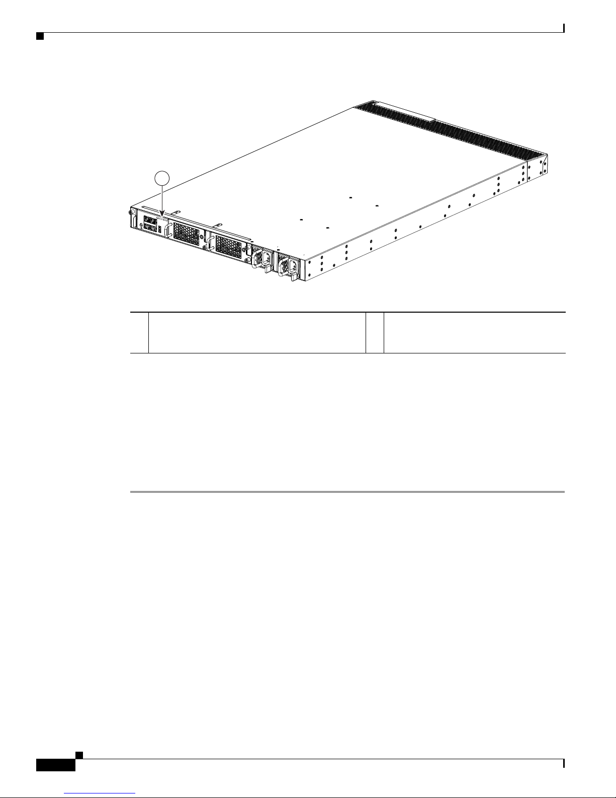
Figure 4-1 Product ID on a Layer 3 I/O Module
1
Chapter 4 Replacing Components
239213
1 Layer 3 modules have an N55-D160L3 or
N55-D160L3-V2 product ID. Layer 2 modules do
not list a PID.
This section includes the following topics:
• Removing an I/O Module, page 4-2
• Installing an I/O Module, page 4-4
Removing an I/O Module
To remove an I/O module from a Cisco Nexus 5548 chassis, follow these steps:
Step 1 Prepare an antistatic surface for placing removed components.
Step 2 On the right fan module, loosen its captive screw so that it is no longer connected to the chassis or I/O
module (see Callout 1 in Figure 4-2).
Cisco Nexus 5000 Series Hardware Installation Guide
4-2
Chapter 4 Replacing Components
2
1
239226
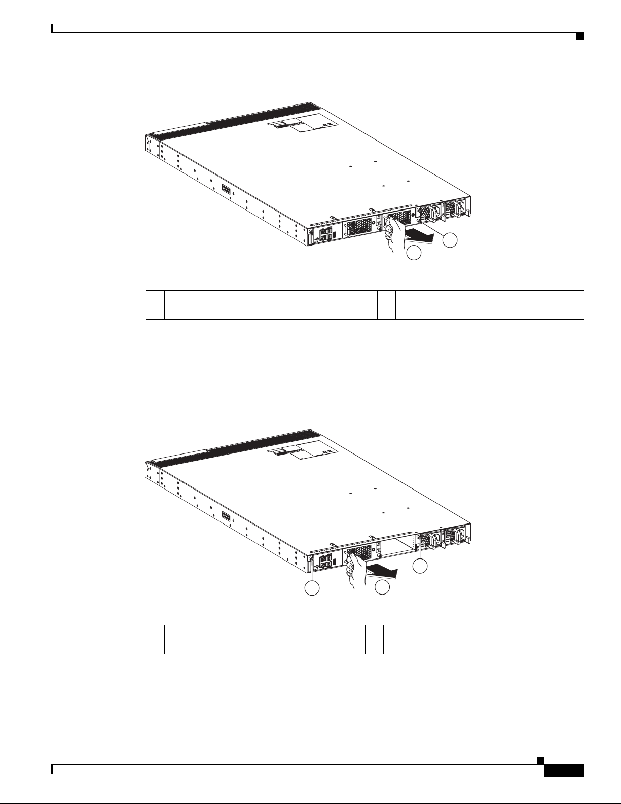
Figure 4-2 Removing a Fan Tray from the I/O Module in the Chassis
Replacing an I/O Module for a Cisco Nexus 5548 Switch
1 Loosen the captive screw on the right most fan
tray so that the screw is free of the I/O module.
Step 3 With a hand on the fan module handle, pull the fan module out of the chassis (see Callout 2 in Figure 4-2)
2 Pull the fan tray out of the I/O module and
set on an antistatic surface.
and place it on an antistatic surface.
Step 4 Loosen the two captive screws on the I/O module so that they are no longer in contact with the chassis
(see Callout 1 in Figure 4-3).
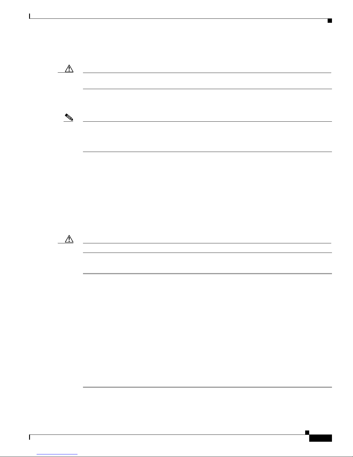
Figure 4-3 Detaching the I/O Module from the Chassis
239227
1
1
2
1 Loosen captive screws until they are no longer
attached to the chassis.
Step 5 Holding the handle for the left fan module, pull the I/O module (which houses the fan module) part way
out of the chassis (see Callout 2 in Figure 4-3).
Step 6 Place your other hand under the I/O module to support its weight, and fully remove the module from the
chassis (see Callout 1 in Figure 4-4).
2 Pull the I/O module part way out of the
chassis.
Cisco Nexus 5000 Series Hardware Installation Guide
4-3

Replacing an I/O Module for a Cisco Nexus 5548 Switch
1
239215
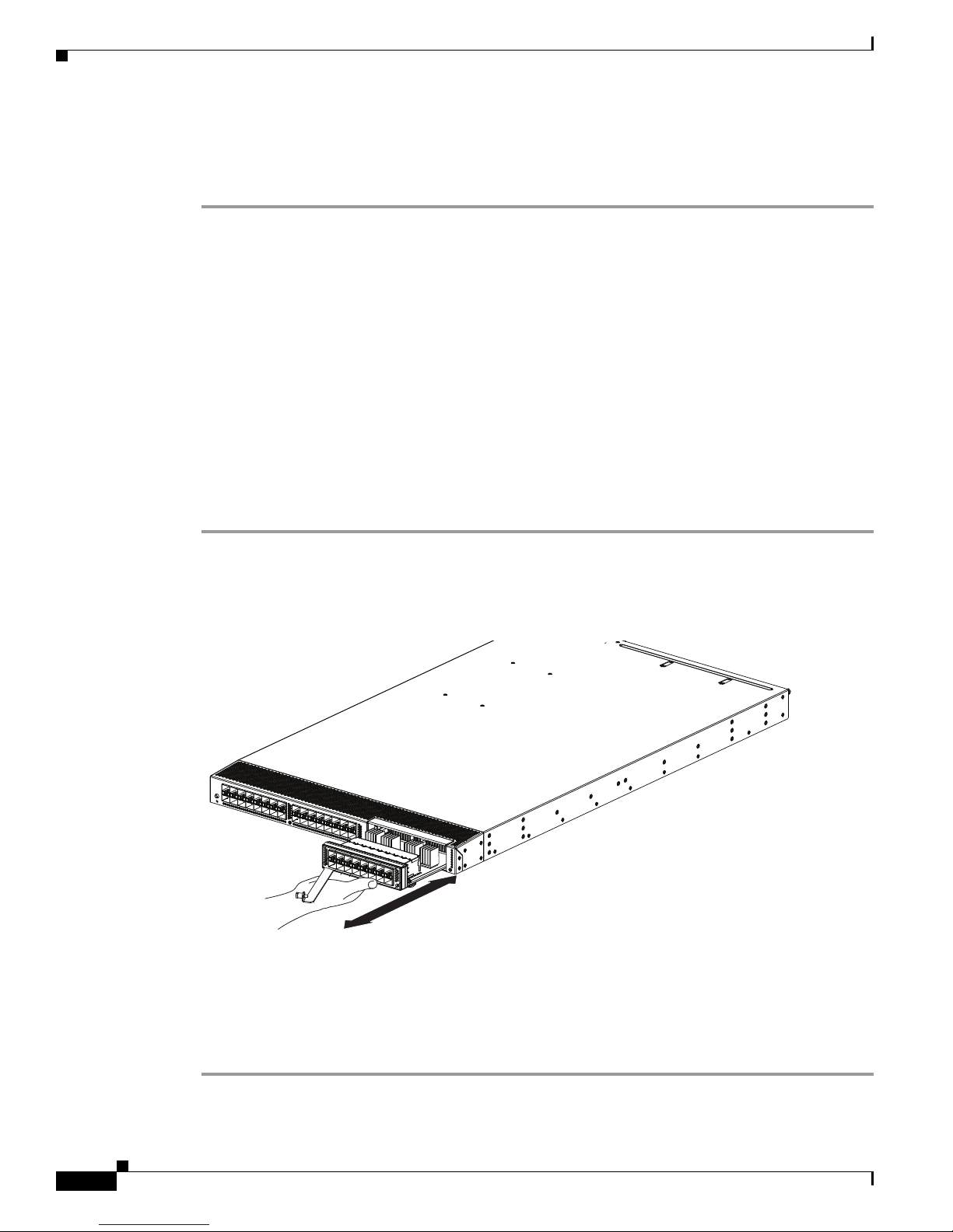
Figure 4-4 Removing the I/O Module from the Chassis
1 Pull the handle on the left fan module to completely
remove the I/O module from the chassis.
Chapter 4 Replacing Components
Step 7 Place the removed I/O module on the antistatic surface.
Step 8 On the remaining fan tray in the I/O module, loosen its captive screw so that it is no longer attached to
the I/O module.
Step 9 Pull the fan tray out of the I/O module.
You are ready to install a replacement I/O module as explained in the “Installing a Fan Module” section
on page 4-14.
Installing an I/O Module
To install an I/O module in a Cisco Nexus 5548 chassis, follow these steps:
Step 1 Align the replacement I/O module to the I/O module slot in the chassis and push the module all the way
into the slot so that its two captive screws are aligned to their holes in the chassis.
Step 2 Tighten both captive screws to the chassis.
Step 3 Install both fan modules into the replacement I/O module (see the “Installing a Fan Module” section on
page 4-14).
Cisco Nexus 5000 Series Hardware Installation Guide
4-4
Chapter 4 Replacing Components
Replacing Expansion Modules
Caution To prevent ESD damage, wear grounding wrist straps during these procedures and handle expansion
modules by the carrier edges only.
Install the switch in the rack before installing expansion modules. For information about installing the
chassis, see the “Installing the Switch” section on page 2-5.
Note Cisco NX-OS Release 5.0(2)N1(1) does not support the hot swapping of a Cisco Nexus 5548 expansion
module during switch operations. Instead, you must power down the switch before removing and
replacing an expansion module. If you are using NX-OS Release 5.0(2)N2(1) or later release, you can
hot swap the expansion modules.
This section includes the following topics:
• Removing an Expansion Module from a Cisco Nexus 5500 Platform Chassis, page 4-5
• Installing an Expansion Module in a Cisco Nexus 5500 Platform Chassis, page 4-6
Replacing Expansion Modules
• Removing an Expansion Module from a Cisco Nexus 5000 Platform Chassis, page 4-6
• Installing an Expansion Module in the Cisco Nexus 5000 Platform Chassis, page 4-7
Removing an Expansion Module from a Cisco Nexus 5500 Platform Chassis
Caution The expansion module must be powered off prior to removal.
To remove an expansion module from the Cisco Nexus 5500 Platform switch chassis, follow these steps:
Step 1 For the Layer 3 GEMs (N55-M160L3 and N55-M160L3-V2) in the Cisco Nexus 5596UP switch, you
must power down the switch first. These expansion modules are not hot swappable.
Step 2 If the switch is able to remain powered on, then power off the expansion module by using the poweroff
module command in global configuration mode.
Step 3 Disconnect any network interface cables attached to the module.
Step 4 Open the packing materials for the module and prepare an antistatic surface for uninstalled modules.
Step 5 Loosen the captive screw on the ejector lever so that the lever can move.
Step 6 Rotate the ejector lever fully from the front of the module until it stops at about 80 degrees from the front.
Step 7 With one hand on the ejector handle and front of the module, pull the module part way out of its slot in
the chassis.
Step 8 Place your other hand under the module to support its weight and fully remove the module.
Step 9 Place the module on an antistatic surface or pack it in its packing materials.
You are ready to install a replacement module in the chassis as described in the “Installing an Expansion
Module in a Cisco Nexus 5500 Platform Chassis” section on page 4-6.
Cisco Nexus 5000 Series Hardware Installation Guide
4-5
Chapter 4 Replacing Components
236714
Replacing Expansion Modules
Installing an Expansion Module in a Cisco Nexus 5500 Platform Chassis
To install an expansion module in a Cisco Nexus 5500 Platform switch chassis, follow these steps:
Step 1 For the Layer 3 GEMs (N55-M160L3 and N55-M160L3-V2) in the Cisco Nexus 5596UP switch, you
must power down the switch first. These expansion modules are not hot swappable.
Step 2 Remove the module from its packing materials and place it on an antistatic surface.
Step 3 If the captive screw on the expansion module is not loose, turn it counterclockwise to fully loosen.
Step 4 Rotate the ejector lever away from the front of the module until it stops at about 80 degrees from the
front.
Step 5 Holding the module with one hand on the front of the module and the other hand on its carrier edges or
bottom, align the module to the open slot.
Step 6 Push the module fully into the slot until the ejector engages and the lever moves.
Step 7 Rotate the ejector lever to the front of the module so that the module is fully inserted in the slot and the
captive screw on the ejector assembly is in position to screw into the expansion module.
Step 8 Tighten the captive screw to the expansion module.
Step 9 Verify the installation by making sure that the module status LED turns on and is green.
Figure 4-5 shows the positioning of an expansion module in the Cisco Nexus 5548 switch chassis.
Figure 4-5 Positioning the Module in the Cisco Nexus 5548 Chassis
Removing an Expansion Module from a Cisco Nexus 5000 Platform Chassis
To remove an expansion module from a Cisco Nexus 5000 Platform chassis, follow these steps:
Step 1 Power off the expansion module by using the poweroff module command in global configuration mode.
Cisco Nexus 5000 Series Hardware Installation Guide
4-6
 Loading...