

Page 1
CHA PT ER
4
Replacing Components
This chapter describes how to remove and install components for the Cisco Nexus 5500 Platform switch
or the Cisco Nexus 5000 Platform switch.
This section includes the following sections:
• Replacing an I/O Module for a Cisco Nexus 5548 Switch, page 4-1
• Replacing Expansion Modules, page 4-5
• Replacing or Installing Power Supplies, page 4-8
• Replacing a Fan Module, page 4-13
• Removing the Cisco Nexus 5500 Platform Chassis or the Cisco Nexus 5000 Platform Chassis,
page 4-17
Caution To prevent ESD damage, wear grounding wrist straps during these procedures and handle modules by
the carrier edges only.
Replacing an I/O Module for a Cisco Nexus 5548 Switch
To replace an I/O module with another I/O module (Layer 2 I/O module or layer 3 I/O module) you must
remove the right fan module and then pull the I/O module out using the handle of the left fan module,
which is installed in the middle of the I/O module. You then install the replacement I/O module and fill
its fan module slots with the fan modules from the original I/O module.
Note If the module includes the product ID on the front, it is a Layer 3 I/O module (product ID N55-D160L3
or N55-D160L3-V2). The N55-D160L3-V2 uses a newer version of the Layer 3 ASIC and enables higher
table sizes in a future software release from 8K host entries to 16K host entries or from 4K multicast
routes to 8K multicast routes (IPv4). The Layer 2 module (product ID N55-DL2) does not include the
product ID on the front.
Cisco Nexus 5000 Series Hardware Installation Guide
4-1
Page 2
Replacing an I/O Module for a Cisco Nexus 5548 Switch
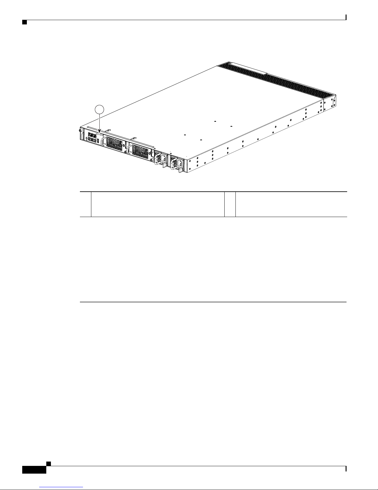
Figure 4-1 Product ID on a Layer 3 I/O Module
1
Chapter 4 Replacing Components
239213
1 Layer 3 modules have an N55-D160L3 or
N55-D160L3-V2 product ID. Layer 2 modules do
not list a PID.
This section includes the following topics:
• Removing an I/O Module, page 4-2
• Installing an I/O Module, page 4-4
Removing an I/O Module
To remove an I/O module from a Cisco Nexus 5548 chassis, follow these steps:
Step 1 Prepare an antistatic surface for placing removed components.
Step 2 On the right fan module, loosen its captive screw so that it is no longer connected to the chassis or I/O
module (see Callout 1 in Figure 4-2).
Cisco Nexus 5000 Series Hardware Installation Guide
4-2
Page 3
Chapter 4 Replacing Components
2
1
239226
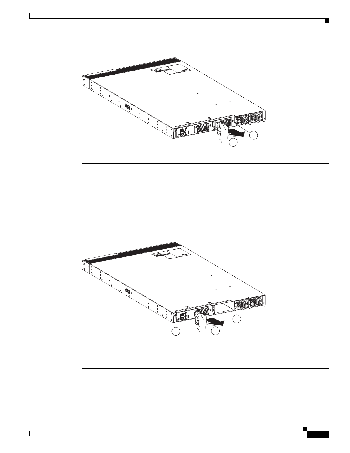
Figure 4-2 Removing a Fan Tray from the I/O Module in the Chassis
Replacing an I/O Module for a Cisco Nexus 5548 Switch
1 Loosen the captive screw on the right most fan
tray so that the screw is free of the I/O module.
Step 3 With a hand on the fan module handle, pull the fan module out of the chassis (see Callout 2 in Figure 4-2)
2 Pull the fan tray out of the I/O module and
set on an antistatic surface.
and place it on an antistatic surface.
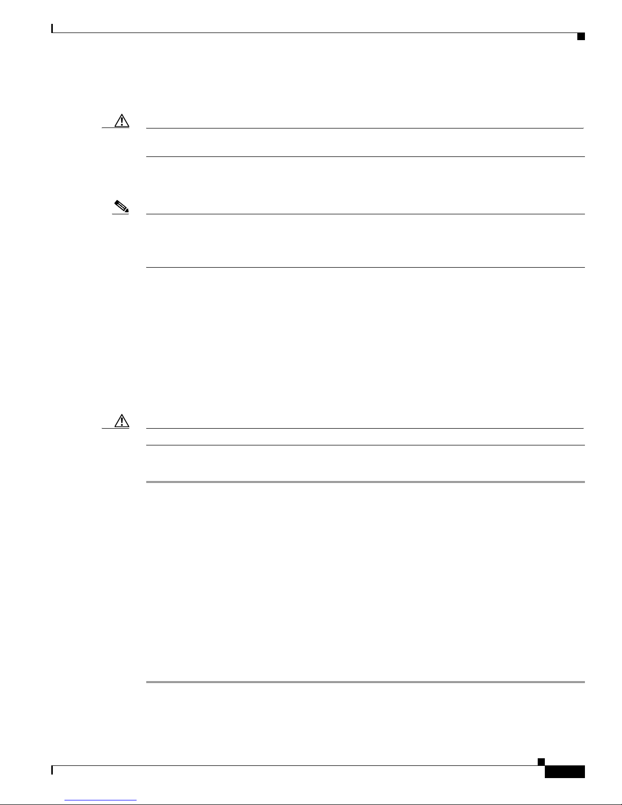
Step 4 Loosen the two captive screws on the I/O module so that they are no longer in contact with the chassis
(see Callout 1 in Figure 4-3).
Figure 4-3 Detaching the I/O Module from the Chassis
239227
1
1
2
1 Loosen captive screws until they are no longer
attached to the chassis.
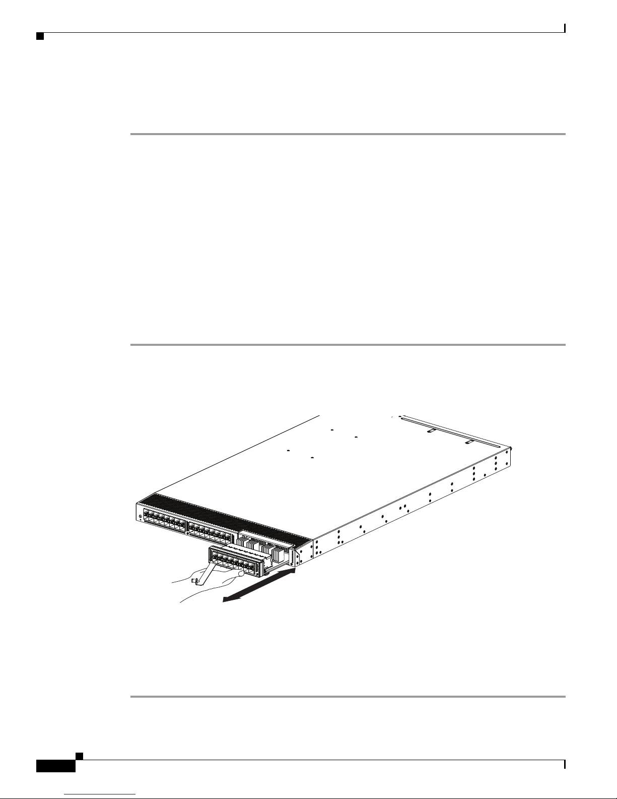
Step 5 Holding the handle for the left fan module, pull the I/O module (which houses the fan module) part way
out of the chassis (see Callout 2 in Figure 4-3).
Step 6 Place your other hand under the I/O module to support its weight, and fully remove the module from the
chassis (see Callout 1 in Figure 4-4).
2 Pull the I/O module part way out of the
chassis.
Cisco Nexus 5000 Series Hardware Installation Guide
4-3
Page 4

Replacing an I/O Module for a Cisco Nexus 5548 Switch
1
239215
Figure 4-4 Removing the I/O Module from the Chassis
1 Pull the handle on the left fan module to completely
remove the I/O module from the chassis.
Chapter 4 Replacing Components
Step 7 Place the removed I/O module on the antistatic surface.
Step 8 On the remaining fan tray in the I/O module, loosen its captive screw so that it is no longer attached to
the I/O module.
Step 9 Pull the fan tray out of the I/O module.
You are ready to install a replacement I/O module as explained in the “Installing a Fan Module” section
on page 4-14.
Installing an I/O Module
To install an I/O module in a Cisco Nexus 5548 chassis, follow these steps:
Step 1 Align the replacement I/O module to the I/O module slot in the chassis and push the module all the way
into the slot so that its two captive screws are aligned to their holes in the chassis.
Step 2 Tighten both captive screws to the chassis.
Step 3 Install both fan modules into the replacement I/O module (see the “Installing a Fan Module” section on
page 4-14).
Cisco Nexus 5000 Series Hardware Installation Guide
4-4
Page 5
Chapter 4 Replacing Components
Replacing Expansion Modules
Caution To prevent ESD damage, wear grounding wrist straps during these procedures and handle expansion
modules by the carrier edges only.
Install the switch in the rack before installing expansion modules. For information about installing the
chassis, see the “Installing the Switch” section on page 2-5.
Note Cisco NX-OS Release 5.0(2)N1(1) does not support the hot swapping of a Cisco Nexus 5548 expansion
module during switch operations. Instead, you must power down the switch before removing and
replacing an expansion module. If you are using NX-OS Release 5.0(2)N2(1) or later release, you can
hot swap the expansion modules.
This section includes the following topics:
• Removing an Expansion Module from a Cisco Nexus 5500 Platform Chassis, page 4-5
• Installing an Expansion Module in a Cisco Nexus 5500 Platform Chassis, page 4-6
Replacing Expansion Modules
• Removing an Expansion Module from a Cisco Nexus 5000 Platform Chassis, page 4-6
• Installing an Expansion Module in the Cisco Nexus 5000 Platform Chassis, page 4-7
Removing an Expansion Module from a Cisco Nexus 5500 Platform Chassis
Caution The expansion module must be powered off prior to removal.
To remove an expansion module from the Cisco Nexus 5500 Platform switch chassis, follow these steps:
Step 1 For the Layer 3 GEMs (N55-M160L3 and N55-M160L3-V2) in the Cisco Nexus 5596UP switch, you
must power down the switch first. These expansion modules are not hot swappable.
Step 2 If the switch is able to remain powered on, then power off the expansion module by using the poweroff
module command in global configuration mode.
Step 3 Disconnect any network interface cables attached to the module.
Step 4 Open the packing materials for the module and prepare an antistatic surface for uninstalled modules.
Step 5 Loosen the captive screw on the ejector lever so that the lever can move.
Step 6 Rotate the ejector lever fully from the front of the module until it stops at about 80 degrees from the front.
Step 7 With one hand on the ejector handle and front of the module, pull the module part way out of its slot in
the chassis.
Step 8 Place your other hand under the module to support its weight and fully remove the module.
Step 9 Place the module on an antistatic surface or pack it in its packing materials.
You are ready to install a replacement module in the chassis as described in the “Installing an Expansion
Module in a Cisco Nexus 5500 Platform Chassis” section on page 4-6.
Cisco Nexus 5000 Series Hardware Installation Guide
4-5
Page 6
Chapter 4 Replacing Components
236714
Replacing Expansion Modules
Installing an Expansion Module in a Cisco Nexus 5500 Platform Chassis
To install an expansion module in a Cisco Nexus 5500 Platform switch chassis, follow these steps:
Step 1 For the Layer 3 GEMs (N55-M160L3 and N55-M160L3-V2) in the Cisco Nexus 5596UP switch, you
must power down the switch first. These expansion modules are not hot swappable.
Step 2 Remove the module from its packing materials and place it on an antistatic surface.
Step 3 If the captive screw on the expansion module is not loose, turn it counterclockwise to fully loosen.
Step 4 Rotate the ejector lever away from the front of the module until it stops at about 80 degrees from the
front.
Step 5 Holding the module with one hand on the front of the module and the other hand on its carrier edges or
bottom, align the module to the open slot.
Step 6 Push the module fully into the slot until the ejector engages and the lever moves.
Step 7 Rotate the ejector lever to the front of the module so that the module is fully inserted in the slot and the
captive screw on the ejector assembly is in position to screw into the expansion module.
Step 8 Tighten the captive screw to the expansion module.
Step 9 Verify the installation by making sure that the module status LED turns on and is green.
Figure 4-5 shows the positioning of an expansion module in the Cisco Nexus 5548 switch chassis.
Figure 4-5 Positioning the Module in the Cisco Nexus 5548 Chassis
Removing an Expansion Module from a Cisco Nexus 5000 Platform Chassis
To remove an expansion module from a Cisco Nexus 5000 Platform chassis, follow these steps:
Step 1 Power off the expansion module by using the poweroff module command in global configuration mode.
Cisco Nexus 5000 Series Hardware Installation Guide
4-6
Page 7

Chapter 4 Replacing Components
Replacing Expansion Modules
Step 2 Loosen the captive screw on the front of the module.
Step 3 Slide the module part way out of its slot and place your other hand under it to support it.
Step 4 Pull the module fully out of the slot and set it on an antistatic surface or repack it in its packing materials.
You are ready to install a replacement module as described in the “Installing an Expansion Module in
the Cisco Nexus 5000 Platform Chassis” section on page 4-7.
Installing an Expansion Module in the Cisco Nexus 5000 Platform Chassis
To install an expansion module in the Cisco Nexus 5000 Platform chassis, follow these steps:
Step 1 Grasp the handle of the module and place your other hand under the module to support it.
Step 2 Gently slide the module into the opening until you cannot push it any further.
Step 3 Tighten the captive screw on the front of the module.
Figure 4-6 shows the positioning of an expansion module in the Cisco Nexus 5020 chassis.
Figure 4-6 Positioning the Module in the Cisco Nexus 5020 Chassis
Figure 4-7 shows the positioning of an expansion module in the Cisco Nexus 5010 chassis.
Cisco Nexus 5000 Series Hardware Installation Guide
4-7
Page 8

Replacing or Installing Power Supplies
Figure 4-7 Positioning the Module in the Cisco Nexus 5010 Chassis
Chapter 4 Replacing Components
273162
Replacing or Installing Power Supplies
The Cisco Nexus 5500 Platform switches and the Cisco Nexus 5000 Platform switches support two
front-end AC or DC power supplies, but may be used with one power supply. The switches each require
one power supply, but you can include a second power supply for power redundancy. If you use only one
power supply, you must fill the second power supply slot with a blank module to maintain the designed
airflow.
If you need to replace an existing power supply, follow the procedures that explain how to remove and
install power supplies. If you are installing a new power supply where one did not exist before, follow
the installation procedure.
You can use port-side exhaust airflow power supply modules for all Cisco Nexus 5000 and 5500 switches
and you can alternatively use port-side intake airflow power supply modules with the Cisco Nexus
5548UP switch.
Caution The Cisco Nexus 5000 and 5500 switches do not support modules using two different directions of
airflow. If you power up a switch with modules using more than one airflow direction, you must power
down the switch before replacing the modules that do not take in air from the cold aisle. When all of the
modules have the same direction of airflow and they are positioned to take in coolant air from the cold
aisle, you may power up the switch.
Note Modules with port-side intake airflow have a black stripe and modules with port-side intake airflow do
not have a colored stripe.
Cisco Nexus 5000 Series Hardware Installation Guide
4-8
Page 9

Chapter 4 Replacing Components
This section includes the following topics:
• Removing a Power Supply, page 4-9
• Installing a Power Supply, page 4-11
• Wiring a DC Power Connector, page 4-12
Note You can replace a faulty power supply while the system is operating if the other power supply is
functioning.
Removing a Power Supply
Caution If you are using a Cisco Nexus 5500 Platform switch or a Cisco Nexus 5000 Platform switch with one
power supply, removing the power supply causes the switch to shut down. If you are using two power
supplies and you remove one of them, the switch can continue to operate.
Replacing or Installing Power Supplies
To remove an AC or DC power supply, follow these steps:
Step 1 Ensure that the system (earth) ground connection has been made. For ground connection instructions,
see the “Grounding the Switch” section on page 2-17.
Step 2 Remove the AC power cord or DC wiring connector.
Step 3 Grasp the power supply handle with your left hand.
Step 4 Push against the release latch with your left thumb, and slide the power supply part way out of the
chassis. To remove a power supply from a Cisco Nexus 5500 Platform chassis, see Figure 4-8 and
Figure 4-9. To remove a power supply from the Cisco Nexus 5020 switch, see Figure 4-10. To remove a
power supply from the Cisco Nexus 5010 switch, see Figure 4-11.
Figure 4-8 Removing the Power Supply from a Cisco Nexus 5596 Switch
Cisco Nexus 5000 Series Hardware Installation Guide
4-9
Page 10

Replacing or Installing Power Supplies
239214
186597
Figure 4-9 Removing the Power Supply from a Cisco Nexus 5548 Switch
Chapter 4 Replacing Components
Figure 4-10 Removing the Power Supply from a Cisco Nexus 5020 Switch
Cisco Nexus 5000 Series Hardware Installation Guide
4-10
Page 11

Chapter 4 Replacing Components
273163
Figure 4-11 Removing the Power Supply from a Cisco Nexus 5010 Switch
Replacing or Installing Power Supplies
Step 5
Place your other hand under the power supply to support its weight, and then completely remove the
module from the slot.
Step 6 If the power supply bay is to remain empty, install a blank power supply filler panel.If you are replacing
the power supply, see Installing a Power Supply, page 4-11
Installing a Power Supply
To install a power supply in a Cisco Nexus 5500 Platform chassis or the Cisco Nexus 5000 Platform
chassis, follow these steps:
Step 1 Ensure that the system (earth) ground connection has been made. For ground connection instructions,
see the “Grounding the Switch” section on page 2-17.
Step 2 If the power supply bay has a filler panel, press the latches on the sides of the filler panel, and then slide
it out of the power supply bay.
Step 3 Hold the power supply by the handle and position it so that the release latch is on the right, and then slide
it into the power supply bay, ensuring that the power supply is fully seated in the bay.
Step 4 Plug the AC power cable or DC wiring connector into the inlet receptacle at the rear of the chassis. For
a DC installation, you should secure the plug to the power supply by tightening both captive screws on
the plug.
Note Depending on the outlet receptacle on your power distribution unit, you may need the optional
jumper power cord to connect the Cisco Nexus 5548 switch to your outlet receptacle. See the
“Jumper Power Cord” section on page C-9.
Step 5 Connect the other end of the power cable to an AC power source. DC sources should connect negative
(black wire) and then positive (red wire) connections.
Caution In a system with dual power supplies, connect each power supply to a separate power source.
In case of a power source failure, the second source will most likely still be available.
Cisco Nexus 5000 Series Hardware Installation Guide
4-11
Page 12

Replacing or Installing Power Supplies
Step 6 Verify the power supply operation by checking that the power supply LED is green.
Wiring a DC Power Connector
Chapter 4 Replacing Components
Warning
Warning
Warning
Warning
Warning
A readily accessible two-poled disconnect device must be incorporated in the fixed wiring.
1022
This product requires short-circuit (overcurrent) protection, to be provided as part of the building
installation. Install only in accordance with national and local wiring regulations.
When installing or replacing the unit, the ground connection must always be made first and
disconnected last.
Installation of the equipment must comply with local and national electrical codes.
Hazardous voltage or energy may be present on DC power terminals. Always replace cover when
terminals are not in service. Be sure uninsulated conductors are not accessible when cover is in
place.
Statement 1075
Statement 1046
Statement 1045
Statement
Statement 1074
Before installing a DC power supply to the switch, you will need to attach DC connection wires that you
provide (10 GA recommended) to the DC power connector included in the DC power supply’s accessory
kit. To wire the connector:
4-12
Step 1 Using a 1/8” flat head screwdriver or No. 1 Phillips head screwdriver, loosen the set screws on the
connector to freely accept the power wires. The connector will accept 8-24 AWG wires, use what your
local electrical code calls for.
Step 2 Strip 1/2” of insulation off the DC wires you will use.
Step 3 Insert the black (DC negative) wire into the right aperture on the connector and tighten down the
connection set screw. Finger tight or about 3 ft./lbs should be sufficient.
Step 4 Insert the red (DC positive) wire into the left aperture on the connector and tighten down the connection
set screw. Do not tighten over 0.7 Nm.
Cisco Nexus 5000 Series Hardware Installation Guide
Page 13

Chapter 4 Replacing Components
330338
2
Figure 4-12 Wiring the DC Power Connector
Replacing a Fan Module
Replacing a Fan Module
The fan module is designed to be removed and replaced while the system is operating without presenting
an electrical hazard or damage to the system, if the replacement is performed promptly.
If you are replacing a fan module, you must replace it with another that uses the same direction of airflow
as all of the other modules in the chassis, and that airflow direction must take in cool air from the cold
aisle and exhaust heated air to the hot aisle. You can use port-side exhaust fan modules with all Cisco
Nexus 5000 switches and you can alternatively use port-side intake fan modules with only the 5548UP
switches.
Caution The Cisco Nexus 5000 and 5500 switches do not support modules using two different directions of
airflow. If you power up a switch with modules using more than one airflow direction, you must power
down the switch before replacing the modules that do not take in air from the cold aisle. When all of the
modules have the same direction of airflow and they are positioned to take in coolant air from the cold
aisle, you may power up the switch.
Cisco Nexus 5000 Series Hardware Installation Guide
4-13
Page 14

Replacing a Fan Module
Note Modules with port-side intake airflow have a black stripe and modules with port-side intake airflow do
not have a colored stripe.
This section includes the following topics:
• Removing a Fan Module, page 4-14
• Installing a Fan Module, page 4-14
Removing a Fan Module
Chapter 4 Replacing Components
Warning
Caution Before you remove a fan module, ensure that the module that you are going to install in the open slot has
When removing the fan tray, keep your hands and fingers away from the spinning fan blades. Let the
fan blades completely stop before you remove the fan tray.
the same direction of airflow as the module that you are removing to avoid over heating the switch and
causing it to shutdown. If the module that you are removing has a black stripe for back-to-front airflow,
the new module must also have a black stripe. If the module that you are removing does not have a black
stripe, then the new module must also not have a black stripe.
To remove a fan module, follow these steps:
Step 1 Loosen the captive screws on the fan module by turning them counterclockwise, using a flat-blade or
number 2 Phillips screwdriver if required.
Step 2 Grasp the handle of fan module and pull it outward.
Step 3 Pull the fan module clear of the chassis.
Installing a Fan Module
Statement 258
Caution Before installing the new fan module, ensure that the module is marked for the same direction of airflow
as all of the other modules installed in the switch. If the installed modules have a black stripe for
back-to-front airflow, then the new module you are installing must have a black stripe. If the installed
modules do not have a black stripe (front-to-back airflow), then the module that you are installing must
also not have a black stripe. If all of the modules are not taking in cold air from the cold aisle, the switch
can overheat and shutdown.
To install a fan module, follow these steps:
Step 1 Hold the fan module with the LED at the bottom (Cisco Nexus 5596 or Cisco Nexus 5020) or right (Cisco
Nexus 5548 or Cisco Nexus 5010).
Cisco Nexus 5000 Series Hardware Installation Guide
4-14
Page 15

Chapter 4 Replacing Components
237998
236716
Step 2 Place the fan module into the front chassis fan slot so it rests on the chassis, and then push the fan module
into the chassis as far as it can go until the captive screw makes contact with the chassis, and tighten the
captive screw. To install a fan module in a Cisco Nexus 5596 chassis, see Figure 4-13. To install a fan
module in a Cisco Nexus 5548 chassis, see Figure 4-14. To install a fan module in a Cisco Nexus 5020
chassis, see Figure 4-15. To install a fan module in a Cisco Nexus 5010 chassis, see Figure 4-16.
Figure 4-13 Installing a Fan Module in a Cisco Nexus 5596 Chassis
Replacing a Fan Module
Figure 4-14 Installing a Fan Module in a Cisco Nexus 5548 Chassis
Cisco Nexus 5000 Series Hardware Installation Guide
4-15
Page 16

Replacing a Fan Module
186596
Figure 4-15 Installing a Fan Module in a Cisco Nexus 5020 Chassis
Chapter 4 Replacing Components
Figure 4-16 Installing a Fan Module in a Cisco Nexus 5010 Chassis
Step 3
If the switch is powered on, listen for the fans. You should immediately hear them operating. If you do
not hear them, ensure that the fan module is inserted completely in the chassis and the faceplate of the
module is flush with the outside surface of the chassis.
Step 4 Verify that the fan module LED is green. If the LED is not green, one or more fans are faulty. If this
situation occurs, contact your customer service representative for one of the following replacement parts:
273164
• Cisco Nexus 5596 fan modules (N5596UP-FAN=)
• Cisco Nexus 5548 fan modules (N5548P-FAN=)
• Cisco Nexus 5020 fan modules (N5K-C5020-FAN=)
• Cisco Nexus 5010 fan modules (N5K-C5010-FAN=)
Cisco Nexus 5000 Series Hardware Installation Guide
4-16
Page 17

Chapter 4 Replacing Components
Removing the Cisco Nexus 5500 Platform Chassis or the Cisco Nexus 5000 Platform Chassis
Note If you purchased this product through a Cisco reseller, contact the reseller directly for technical support.
If you purchased this product directly from Cisco, contact Cisco Technical Support at this URL:
http://www.cisco.com/c/en/us/support/web/tsd-cisco-worldwide-contacts.html.
Removing the Cisco Nexus 5500 Platform Chassis or the Cisco
Nexus 5000 Platform Chassis
Caution The slider rail and front rack-mount brackets do not have a stop mechanism when sliding in and out. If
the front of the chassis is unfastened from the rack and the chassis slides forward on the slider rails, it
might slip off the end of the rails and fall out of the rack.
To remove the Cisco Nexus 5500 Platform chassis or the Cisco Nexus 5000 Platform chassis from a rack,
follow these steps:
Step 1 Ensure that the weight of the switch is fully supported and that the switch is being held by another
person.
Step 2 Disconnect the power cord and the console cables.
Step 3 Disconnect all cables that are connected to SFP+ transceivers.
Step 4 Remove the screws fastening the front rack-mount brackets to the mounting rails.
Step 5 Gently slide the switch towards you, off of the slider rails and out of the rack.
Repacking Cisco Nexus 5500 Platform Switch Components or
Cisco Nexus 5000 Platform Switch Components for Return
Shipment
If you need to return the switch, remove the switch from the rack by following the steps in the
“Removing the Cisco Nexus 5500 Platform Chassis or the Cisco Nexus 5000 Platform Chassis” section
on page 4-17, and repack it for shipment. If possible, use the original packing materials and container to
repack the switch. Contact your Cisco customer service representative to arrange for return shipment to
Cisco.
Cisco Nexus 5000 Series Hardware Installation Guide
4-17
Page 18

Repacking Cisco Nexus 5500 Platform Switch Components or Cisco Nexus 5000 Platform Switch Components for
Chapter 4 Replacing Components
Cisco Nexus 5000 Series Hardware Installation Guide
4-18
 Loading...