

Page 1

Cisco Nexus 5000 NX-OS Quality of Service Configuration Guide, Release 5.1(3)N2(1)
First Published: March 13, 2012
Last Modified: February 12, 2013
Americas Headquarters
Cisco Systems, Inc.
170 West Tasman Drive
San Jose, CA 95134-1706
USA
http://www.cisco.com
Tel: 408 526-4000
800 553-NETS (6387)
Fax: 408 527-0883
Text Part Number: OL-26657-01
Page 2

THE SPECIFICATIONS AND INFORMATION REGARDING THE PRODUCTS IN THIS MANUAL ARE SUBJECT TO CHANGE WITHOUT NOTICE. ALL STATEMENTS,
INFORMATION, AND RECOMMENDATIONS IN THIS MANUAL ARE BELIEVED TO BE ACCURATE BUT ARE PRESENTED WITHOUT WARRANTY OF ANY KIND,
EXPRESS OR IMPLIED. USERS MUST TAKE FULL RESPONSIBILITY FOR THEIR APPLICATION OF ANY PRODUCTS.
THE SOFTWARE LICENSE AND LIMITED WARRANTY FOR THE ACCOMPANYING PRODUCT ARE SET FORTH IN THE INFORMATION PACKET THAT SHIPPED WITH
THE PRODUCT AND ARE INCORPORATED HEREIN BY THIS REFERENCE. IF YOU ARE UNABLE TO LOCATE THE SOFTWARE LICENSE OR LIMITED WARRANTY,
CONTACT YOUR CISCO REPRESENTATIVE FOR A COPY.
The Cisco implementation of TCP header compression is an adaptation of a program developed by the University of California, Berkeley (UCB) as part of UCB's public domain version
of the UNIX operating system. All rights reserved. Copyright©1981, Regents of the University of California.
NOTWITHSTANDING ANY OTHER WARRANTY HEREIN, ALL DOCUMENT FILES AND SOFTWARE OF THESE SUPPLIERS ARE PROVIDED “AS IS" WITH ALL FAULTS.
CISCO AND THE ABOVE-NAMED SUPPLIERS DISCLAIM ALL WARRANTIES, EXPRESSED OR IMPLIED, INCLUDING, WITHOUT LIMITATION, THOSE OF
MERCHANTABILITY, FITNESS FOR A PARTICULAR PURPOSE AND NONINFRINGEMENT OR ARISING FROM A COURSE OF DEALING, USAGE, OR TRADE PRACTICE.
IN NO EVENT SHALL CISCO OR ITS SUPPLIERS BE LIABLE FOR ANY INDIRECT, SPECIAL, CONSEQUENTIAL, OR INCIDENTAL DAMAGES, INCLUDING, WITHOUT
LIMITATION, LOST PROFITS OR LOSS OR DAMAGE TO DATA ARISING OUT OF THE USE OR INABILITY TO USE THIS MANUAL, EVEN IF CISCO OR ITS SUPPLIERS
HAVE BEEN ADVISED OF THE POSSIBILITY OF SUCH DAMAGES.
Any Internet Protocol (IP) addresses and phone numbers used in this document are not intended to be actual addresses and phone numbers. Any examples, command display output, network
topology diagrams, and other figures included in the document are shown for illustrative purposes only. Any use of actual IP addresses or phone numbers in illustrative content is unintentional
and coincidental.
Cisco and the Cisco logo are trademarks or registered trademarks of Cisco and/or its affiliates in the U.S. and other countries. To view a list of Cisco trademarks, go to this URL: http://
www.cisco.com/go/trademarks. Third-party trademarks mentioned are the property of their respective owners. The use of the word partner does not imply a partnership
relationship between Cisco and any other company. (1110R)
©
2012-2013 Cisco Systems, Inc. All rights reserved.
Page 3

CONTENTS
Preface
CHAPTER 1
CHAPTER 2
CHAPTER 3
Preface vii
Audience vii
Document Conventions vii
Documentation Feedback viii
Obtaining Documentation and Submitting a Service Request ix
New and Changed Information 1
New and Changed Information for this Release 1
Overview 3
Information About Quality of Service 3
Modular QoS CLI 3
QoS for Traffic Directed to the CPU 5
Configuring Classification 7
Information About Classification 7
Ingress Classification Policies 8
Licensing Requirements for Classification 8
Configuring Classification 8
Configuring Class Maps 8
Configuring CoS Classification 9
Configuring Precedence Classification 10
Configuring DSCP Classification 12
Configuring Protocol Classification 13
Configuring IP RTP Classification 14
Configuring ACL Classification 15
Verifying the Classification Configuration 16
Cisco Nexus 5000 NX-OS Quality of Service Configuration Guide, Release 5.1(3)N2(1)
OL-26657-01 iii
Page 4

Contents
CHAPTER 4
CHAPTER 5
Configuring Policy Maps 17
Information About Policy Types 17
Configuring Policy Maps 19
Creating Policy Maps 19
Configuring Type QoS Policies 21
Configuring Type Network QoS Policies 22
Configuring Type Queuing Policies 23
Verifying the Policy Map Configuration 24
Configuring Marking 27
Information About Marking 27
Configuring Marking 27
Configuring DSCP Marking 27
Configuring IP Precedence Marking 29
Configuring CoS Marking 30
Required CoS Marking Configuration in a Layer 3 Topology 31
CHAPTER 6
CHAPTER 7
Verifying the Marking Configuration 32
Configuring QoS on the System 35
Information About System Classes 35
System Classes 35
Default System Classes 35
MTU 36
Configuring System QoS 37
Attaching the System Service Policy 37
Restoring the Default System Service Policies 38
Configuring the Queue Limit for a Specified Fabric Extender 39
Enabling the Jumbo MTU 40
Verifying the Jumbo MTU 41
Verifying the System QoS Configuration 41
Configuring QoS on Interfaces 43
Information About Interface QoS 43
Trust Boundaries 43
Cisco Nexus 5000 NX-OS Quality of Service Configuration Guide, Release 5.1(3)N2(1)
iv OL-26657-01
Page 5

Contents
Policy for Fibre Channel Interfaces 44
QoS for Multicast Traffic 44
Configuring Interface QoS 45
Configuring Untagged CoS 45
Configuring an Interface Service Policy 45
Configuring a Service Policy for a Layer 3 Interface 46
Verifying the Interface QoS Configuration 47
CHAPTER 8
Configuring QoS on VLANs 49
Information About VLAN QoS 49
Precedence of QoS Policies 49
Example of Interface, System, and VLAN Policy Precedence 50
Example of Interface and System QoS Policy Precedence 50
Example of System and VLAN Policy Precedence 50
Example of VLAN QoS and VACL Policy Precedence 51
Limiting TCAM Entries for VLAN QoS 52
Guidelines and Limitations for VLAN QoS 52
Configuring VLAN QoS 53
Configuring or Changing the Interface QoS TCAM Limit 53
Removing the Interface QoS Limit from the TCAM 54
Configuring a Service Policy on a VLAN 54
Removing a Service Policy from a VLAN 55
Verifying the VLAN QoS Configuration 56
Feature History for VLAN QoS 56
CHAPTER 9
Configuring Queuing and Flow Control 57
Information About Queues 57
Ingress Queuing Policies 57
Egress Queuing Policies 57
Buffering and Queue Limits on the Cisco Nexus 5000 Platform 58
Buffering and Queue Limits on the Cisco Nexus Device 59
Information About Flow Control 60
Link-Level Flow Control 60
Priority Flow Control 60
Configuring Queuing 61
Cisco Nexus 5000 NX-OS Quality of Service Configuration Guide, Release 5.1(3)N2(1)
OL-26657-01 v
Page 6

Contents
Configuring the Queue Limit for a Specified Fabric Extender 61
Configuring No-Drop Buffer Thresholds 62
Configuring the Buffer Threshold for the Cisco Nexus 2148T Fabric Extender 63
Enabling Virtual Output Queuing Limits for Unicast Traffic on the Cisco Nexus Device 64
Configuring Flow Control 65
Link-Level Flow Control 65
Configuring Priority Flow Control 65
Configuring Link-Level Flow Control 66
Disabling Slow Port Pruning on Multicast Traffic on the Cisco Nexus 5500 Series
Device 66
Verifying the Queue and Flow Control Configurations 67
CHAPTER 10
QoS Configuration Examples 69
QoS Example 1 69
QoS Example 2 70
QoS Example 3 72
Cisco Nexus 5000 NX-OS Quality of Service Configuration Guide, Release 5.1(3)N2(1)
vi OL-26657-01
Page 7

Preface
The Preface contains the following sections:
Audience, page vii
•
Document Conventions, page vii
•
Documentation Feedback, page viii
•
Obtaining Documentation and Submitting a Service Request, page ix
•
Audience
This publication is for network administrators who configure and maintain Cisco Nexus devices and Cisco
Nexus 2000 Series Fabric Extenders.
Document Conventions
Command descriptions use the following conventions:
DescriptionConvention
bold
Italic
[x | y]
{x | y}
Cisco Nexus 5000 NX-OS Quality of Service Configuration Guide, Release 5.1(3)N2(1)
OL-26657-01 vii
Bold text indicates the commands and keywords that you enter literally
as shown.
Italic text indicates arguments for which the user supplies the values.
Square brackets enclose an optional element (keyword or argument).[x]
Square brackets enclosing keywords or arguments separated by a vertical
bar indicate an optional choice.
Braces enclosing keywords or arguments separated by a vertical bar
indicate a required choice.
Page 8

Documentation Feedback
Preface
DescriptionConvention
[x {y | z}]
Nested set of square brackets or braces indicate optional or required
choices within optional or required elements. Braces and a vertical bar
within square brackets indicate a required choice within an optional
element.
variable
Indicates a variable for which you supply values, in context where italics
cannot be used.
string
A nonquoted set of characters. Do not use quotation marks around the
string or the string will include the quotation marks.
Examples use the following conventions:
DescriptionConvention
Terminal sessions and information the switch displays are in screen font.screen font
Information you must enter is in boldface screen font.boldface screen font
italic screen font
Arguments for which you supply values are in italic screen font.
Nonprinting characters, such as passwords, are in angle brackets.< >
Default responses to system prompts are in square brackets.[ ]
!, #
This document uses the following conventions:
Note
Means reader take note. Notes contain helpful suggestions or references to material not covered in the
manual.
Caution
Means reader be careful. In this situation, you might do something that could result in equipment damage
or loss of data.
Documentation Feedback
To provide technical feedback on this document, or to report an error or omission, please send your comments
to: ciscodfa-docfeedback@cisco.com.
We appreciate your feedback.
An exclamation point (!) or a pound sign (#) at the beginning of a line
of code indicates a comment line.
Cisco Nexus 5000 NX-OS Quality of Service Configuration Guide, Release 5.1(3)N2(1)
viii OL-26657-01
Page 9

Preface
Obtaining Documentation and Submitting a Service Request
Obtaining Documentation and Submitting a Service Request
For information on obtaining documentation, using the Cisco Bug Search Tool (BST), submitting a service
request, and gathering additional information, see What's New in Cisco Product Documentation, at: http://
www.cisco.com/c/en/us/td/docs/general/whatsnew/whatsnew.html.
Subscribe to What's New in Cisco Product Documentation, which lists all new and revised Cisco technical
documentation as an RSS feed and delivers content directly to your desktop using a reader application. The
RSS feeds are a free service.
Cisco Nexus 5000 NX-OS Quality of Service Configuration Guide, Release 5.1(3)N2(1)
OL-26657-01 ix
Page 10

Obtaining Documentation and Submitting a Service Request
Preface
Cisco Nexus 5000 NX-OS Quality of Service Configuration Guide, Release 5.1(3)N2(1)
x OL-26657-01
Page 11

CHAPTER 1
New and Changed Information
This chapter contains the following sections:
New and Changed Information for this Release, page 1
•
New and Changed Information for this Release
The following table provides an overview of the significant changes to this guide for this current release. The
table does not provide an exhaustive list of all changes made to the configuration guide or of the new features
in this release.
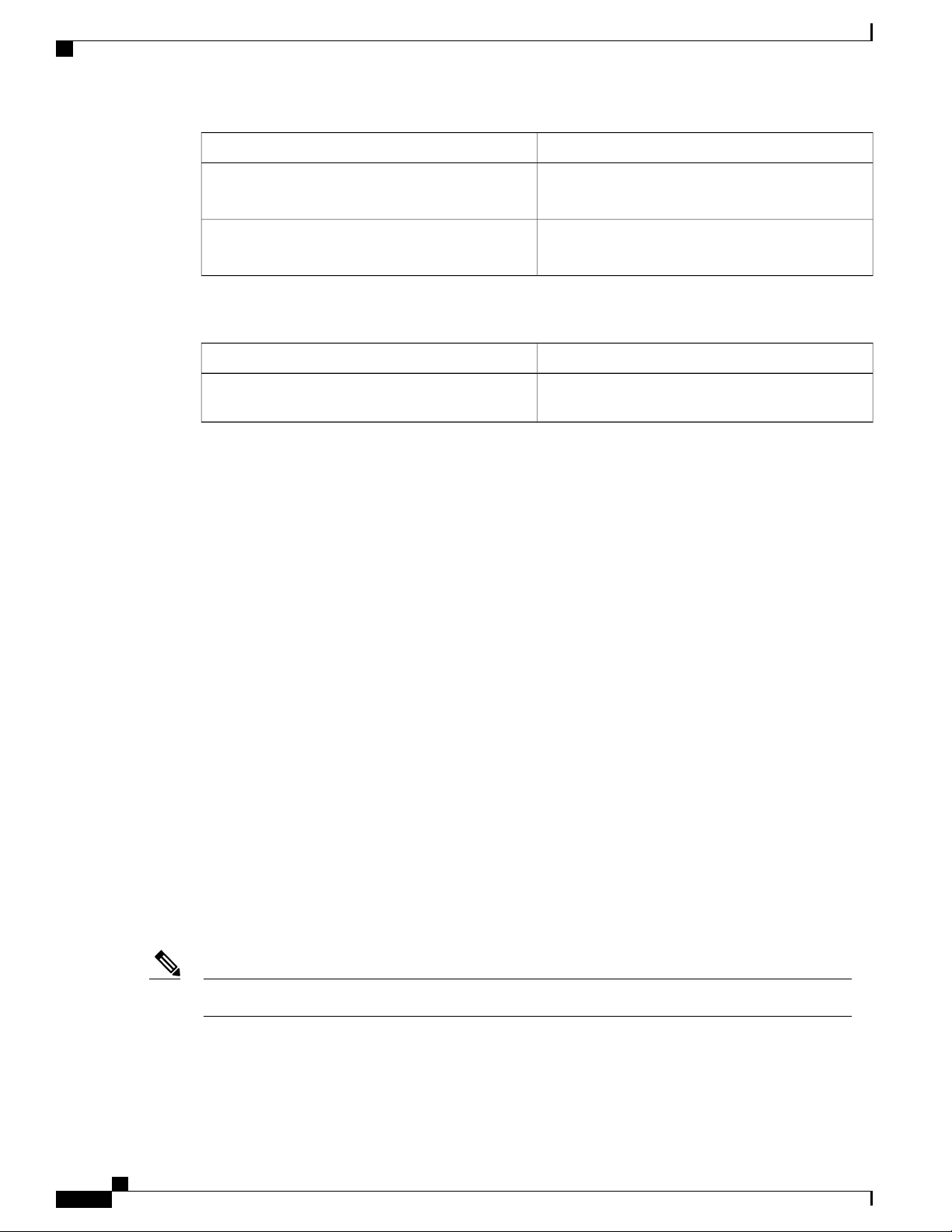
Where DocumentedDescriptionFeature
Support for QoS VLANs.VLAN QoS
Configuring QoS on VLANs, on
page 49
Cisco Nexus 5000 NX-OS Quality of Service Configuration Guide, Release 5.1(3)N2(1)
OL-26657-01 1
Page 12

New and Changed Information for this Release
New and Changed Information
Cisco Nexus 5000 NX-OS Quality of Service Configuration Guide, Release 5.1(3)N2(1)
2 OL-26657-01
Page 13

Overview
This chapter contains the following sections:
Information About Quality of Service, page 3
•
Modular QoS CLI, page 3
•
QoS for Traffic Directed to the CPU , page 5
•
Information About Quality of Service
The configurable Cisco NX-OS quality of service (QoS) features allow you to classify the network traffic,
prioritize the traffic flow, and provide congestion avoidance.
The default QoS configuration on the device provides lossless service for Fibre Channel and Fibre Channel
over Ethernet (FCoE) traffic and best-effort service for Ethernet traffic. QoS can be configured to provide
additional classes of service for Ethernet traffic. Cisco NX-OS QoS features are configured using Cisco
Modular QoS CLI (MQC).
Standard Ethernet is a best-effort medium which means that it lacks any form of flow control. In the event of
congestion or collisions, Ethernet will drop packets. The higher level protocols detect the missing data and
retransmit the dropped packets.
Fibre Channel requires a reliable transport system that guarantees the delivery of every packet. To properly
support FCoE, Ethernet has been enhanced with a priority flow control (PFC) mechanism to prevent congestion.
The FCoE QoS must be configured either if native FC or FCoE or FC and FCoE are in use. The FCoE QoS
must be added even if Ethernet is not configured on the switch.
The following commands will enable the default QoS configuration:
switch(config)# system qos
switch(config-sys-qos)# service-policy type queuing input fcoe-default-in-policy
switch(config-sys-qos)# service-policy type queuing output fcoe-default-out-policy
switch(config-sys-qos)# service-policy type qos input fcoe-default-in-policy
switch(config-sys-qos)# service-policy type network-qos fcoe-default-nq-policy
CHAPTER 2
Modular QoS CLI
The Cisco Modular QoS CLI (MQC) provides a standard set of commands for configuring QoS.
Cisco Nexus 5000 NX-OS Quality of Service Configuration Guide, Release 5.1(3)N2(1)
OL-26657-01 3
Page 14

Modular QoS CLI
Overview
You can use MQC to define additional traffic classes and to configure QoS policies for the whole system and
for individual interfaces. Configuring a QoS policy with MQC consists of the following steps:
1
Define traffic classes.
2
Associate policies and actions with each traffic class.
3
Attach policies to logical or physical interfaces as well as at the global system level.
MQC provides two command types to define traffic classes and policies:
class-map
Defines a class map that represents a class of traffic based on packet-matching criteria. Class maps are
referenced in policy maps.
The class map classifies incoming packets based on matching criteria, such as the IEEE 802.1p class
of service (CoS) value. Unicast and multicast packets are classified.
policy-map
Defines a policy map that represents a set of policies to be applied on a class-by-class basis to class
maps.
The policy map defines a set of actions to take on the associated traffic class, such as limiting the
bandwidth or dropping packets.
Note
You define the following class-map and policy-map object types when you create them:
network-qos
Defines MQC objects that you can use for system level related actions.
qos
Defines MQC objects that you can use for classification.
queuing
Defines MQC objects that you can use for queuing and scheduling.
The qos type is the default for the class-map and policy-map commands, but not for the service-policy
which requires that you specify an explicit type.
You can attach policies to interfaces or EtherChannels as well as at the global system level by using the
service-policy command.
You can view all or individual values for MQC objects by using the show class-map and show policy-map
commands.
An MQC target is an entity (such as an Ethernet interface) that represents a flow of packets. A service policy
associates a policy map with an MQC target and specifies whether to apply the policy on incoming or outgoing
packets. This mapping enables the configuration of QoS policies such as marking, bandwidth allocation,
buffer allocation, and so on.
Cisco Nexus 5000 NX-OS Quality of Service Configuration Guide, Release 5.1(3)N2(1)
4 OL-26657-01
Page 15

Overview
QoS for Traffic Directed to the CPU
The device automatically applies QoS policies to traffic that is directed to the CPU to ensure that the CPU is
not flooded with packets. Control traffic, such as bridge protocol data units (BPDU) frames, is given higher
priority to ensure delivery.
QoS for Traffic Directed to the CPU
Cisco Nexus 5000 NX-OS Quality of Service Configuration Guide, Release 5.1(3)N2(1)
OL-26657-01 5
Page 16

QoS for Traffic Directed to the CPU
Overview
Cisco Nexus 5000 NX-OS Quality of Service Configuration Guide, Release 5.1(3)N2(1)
6 OL-26657-01
Page 17

Configuring Classification
This chapter contains the following sections:
Information About Classification, page 7
•
Ingress Classification Policies, page 8
•
Licensing Requirements for Classification, page 8
•
Configuring Classification, page 8
•
Verifying the Classification Configuration, page 16
•
Information About Classification
Classification is the separation of packets into traffic classes. You configure the device to take a specific action
on the specified classified traffic, such as policing or marking down, or other actions.
You can create class maps to represent each traffic class by matching packet characteristics with classification
criteria.
CHAPTER 3
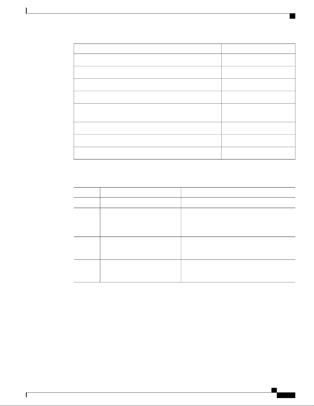
Table 1: Classification Criteria
DescriptionClassification Criteria
Criteria specified in a named class-map object.Class map
Precedence
Differentiated Services Code Point (DSCP)
Protocol
Cisco Nexus 5000 NX-OS Quality of Service Configuration Guide, Release 5.1(3)N2(1)
OL-26657-01 7
Precedence value within the Type of Service (ToS)
byte of the IP Header.
DSCP value within the DIffServ field of the IP
Header.
Selected set of protocols, including Address
Resolution Protocol (ARP) and Connectionless
Network Service (CLNS).
Page 18
Ingress Classification Policies
Configuring Classification
DescriptionClassification Criteria
IP RTP
ACL
Table 2: Supported RFCs
RFC 2474
Ingress Classification Policies
You use classification to partition traffic into classes. You classify the traffic based on the packet property
(CoS field) or the packet header fields that include IP precedence, Differentiated Services Code Point (DSCP),
and Layer 2 to Layer 4 parameters. The values used to classify traffic are called match criteria.
Traffic that fails to match any class is assigned to a default class of traffic called class-default.
Identify applications using Real-time Transport
Protocol (RTP) by UDP port number range.
Traffic is classified by the criteria defined in the
access control list (ACL).
TitleRFC
Definition of the Differentiated Services Field (DS
Field) in the IPv4 and IPv6 Headers
Licensing Requirements for Classification
This feature does not require a license. Any feature not included in a license package is bundled with the Cisco
NX-OS system images and is provided at no extra charge to you. For a complete explanation of the Cisco
NX-OS licensing scheme, see the Cisco NX-OS Licensing Guide.
Configuring Classification
Configuring Class Maps
You can create or modify a class map with the class-map command. The class map is a named object that
represents a class of traffic. In the class map, you specify a set of match criteria for classifying the packets.
You can then reference class maps in policy maps.
The class map type default is type qos and its match criteria default is match-all.Note
Cisco Nexus 5000 NX-OS Quality of Service Configuration Guide, Release 5.1(3)N2(1)
8 OL-26657-01
Page 19

Configuring Classification
Configuring CoS Classification
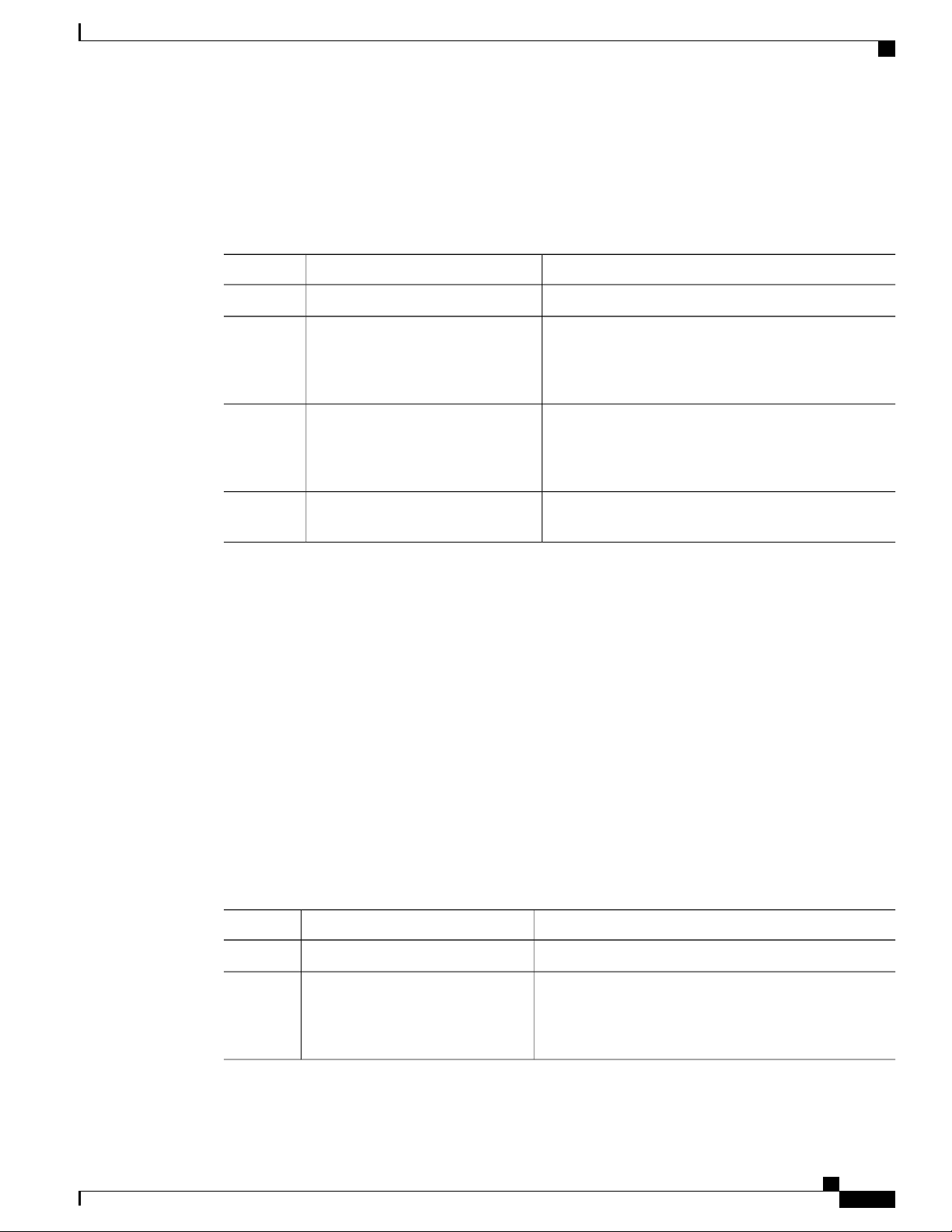
Procedure
PurposeCommand or Action
Step 1
Step 2
Step 3
switch(config)# class-map
[type {network-qos | qos |
queuing}] class-map name
switch(config)# class-map
[type qos] [match-all |
match-any] class-map name
Enters global configuration mode.switch# configure terminal
Creates or accesses a named object that represents the specified class
of traffic.
Class-map names can contain alphabetic, hyphen, or underscore
characters, are case sensitive, and can be up to 40 characters.
The three class-map configuration modes are as follows:
• network-qos—Network-wide (global) mode. CLI prompt:
switch(config-cmap-nq)#
• qos—Classification mode; this is the default mode. CLI
prompt: switch(config-cmap-qos)#
• queuing—Queuing mode. CLI prompt:
switch(config-cmap-que)#
(Optional)
Specifies that packets must match any or all criteria that is defined
for a class map.
• match-all—Classifies traffic if packets match all criteria that
is defined for a specified class map (for example, if both the
defined CoS and the ACL criteria match).
• match-any—Classifies traffic if packets match any criteria
that is defined for a specified class map (for example, if either
the CoS or the ACL criteria matches).
Class-map names can contain alphabetic, hyphen, or underscore
characters, are case sensitive, and can be up to 40 characters.
Step 4
switch(config)# no class-map
[type {network-qos | qos |
queuing}] class-name
(Optional)
Deletes the specified class map.
Note
You cannot delete the two system-defined class maps:
class-fcoe and class-default.
Class-map names can contain alphabetic, hyphen, or underscore
characters, are case sensitive, and can be up to 40 characters.
Configuring CoS Classification
You can classify traffic based on the class of service (CoS) in the IEEE 802.1Q header. This 3-bit field is
defined in IEEE 802.1p to support QoS traffic classes. CoS is encoded in the high order 3 bits of the VLAN
ID Tag field and is referred to as user_priority.
Cisco Nexus 5000 NX-OS Quality of Service Configuration Guide, Release 5.1(3)N2(1)
OL-26657-01 9
Page 20

Configuring Precedence Classification
The Cisco Nexus 2148 Fabric Extender does not support frames with the dot1p vlan 0 tag.Note
If a system class is configured with a no-drop function, the match cos command serves an additional purpose.
The switch sends the CoS value to the adapter so that the adapter will apply a PFC pause for this CoS value.
The FCoE system class has a default CoS value of 3. You can add a match cos configuration to the FCoE
system class to set a different CoS value. A PFC pause will be applied to traffic that matches the new value.
Procedure
Configuring Classification
PurposeCommand or Action
Step 1
Step 2
switch(config)# class-map type
qos class-name
Enters global configuration mode.switch# configure terminal
Creates a named object that represents a class of traffic.
Class-map names can contain alphabetic, hyphen, or
underscore characters, are case sensitive, and can be up to 40
characters.
Step 3
switch(config-cmap-qos)# match
cos cos-value
Specifies the CoS value to match for classifying packets into
this class. You can configure a CoS value in the range of 0
to 7.
Note
When a Cisco Nexus 2148T Fabric Extender is
connected and in use, data traffic should never be
marked with a CoS value of 7. CoS 7 is reserved for
control traffic transiting the Fabric Extender.
Step 4
switch(config-cmap-qos)# no
match cos cos-value
(Optional)
Removes the match from the traffic class.
This example shows how to classify traffic by matching packets based on a defined CoS value:
switch# configure terminal
switch(config)# class-map type qos match-any class_cos
switch(config-cmap-qos)# match cos 4, 5-6
Use the show class-map command to display the CoS value class-map configuration:
switch# show class-map class_cos
Configuring Precedence Classification
You can classify traffic based on the precedence value in the type of service (ToS) byte field of the IP header
(either IPv4 or IPv6). The following table shows the precedence values:
Table 3: Precedence Values
List of Precedence ValuesValue
IP precedence value<0-7>
Cisco Nexus 5000 NX-OS Quality of Service Configuration Guide, Release 5.1(3)N2(1)
10 OL-26657-01
Page 21
Configuring Classification
Configuring Precedence Classification
List of Precedence ValuesValue
Critical precedence (5)critical
Flash precedence (3)flash
Flash override precedence (4)flash-override
Immediate precedence (2)immediate
internet
Procedure
Step 1
Step 2
Step 3
switch(config)# class-map type qos
match-any class-name
switch(config-cmap-qos)#match
precedence precedence-values
Internetwork control precedence
(6)
Network control precedence (7)network
Priority precedence (1)priority
Routine precedence (0)routine
PurposeCommand or Action
Enters global configuration mode.switch# configure terminal
Creates a named object that represents a class of traffic.
Class-map names can contain alphabetic, hyphen, or
underscore characters, are case sensitive, and can be up
to 40 characters.
Configures the traffic class by matching packets based
on precedence values. For a list of precedence values,
see the Precedence Values table.
Step 4
switch((config-cmap-qos)# no match
precedence precedence-values
(Optional)
Removes the match from the traffic class. For a list of
precedence values, see the Precedence Values table.
This example shows how to classify traffic by matching packets based on the precedence value in the ToS
byte field of the IP header:
switch# configure terminal
switch(config)# class-map type qos match-any class_precedence
switch(config-cmap-qos)# match precedence 1-2, critical
Use the show class-map command to display the IP precedence value class-map configuration:
switch# show class-map class_precedence
Cisco Nexus 5000 NX-OS Quality of Service Configuration Guide, Release 5.1(3)N2(1)
OL-26657-01 11
Page 22

Configuring DSCP Classification
Configuring DSCP Classification
You can classify traffic based on the Differentiated Services Code Point (DSCP) value in the DiffServ field
of the IP header (either IPv4 or IPv6).
Table 4: Standard DSCP Values
Configuring Classification
List of DSCP ValuesValue
af11
af12
af13
af21
af22
af23
af31
af32
af33
af41
af42
af43
AF11 dscp (001010)—decimal value 10
AF12 dscp (001100)—decimal value 12
AF13 dscp (001110)—decimal value 14
AF21 dscp (010010)—decimal value 18
AF22 dscp (010100)—decimal value 20
AF23 dscp (010110)—decimal value 22
AF31 dscp (011010)—decimal value 26
AF32 dscp (011100)—decimal value 28
AF33 dscp (011110)—decimal value 30
AF41 dscp (100010)—decimal value 34
AF42 dscp (100100)—decimal value 36
AF43 dscp (100110)—decimal value 38
cs1
CS1 (precedence 1) dscp (001000)—decimal value
8
cs2
CS2 (precedence 2) dscp (010000)—decimal value
16
cs3
CS3 (precedence 3) dscp (011000)—decimal value
24
cs4
CS4 (precedence 4) dscp (100000)—decimal value
32
cs5
CS5 (precedence 5) dscp (101000)—decimal value
40
Cisco Nexus 5000 NX-OS Quality of Service Configuration Guide, Release 5.1(3)N2(1)
12 OL-26657-01
Page 23

Configuring Classification
Configuring Protocol Classification
List of DSCP ValuesValue
cs6
cs7
default
ef
Procedure
Step 1
Step 2
Step 3
switch(config)# class-map type qos
class-name
switch(config-cmap-qos)# match
dscp dscp-list
CS6 (precedence 6) dscp (110000)—decimal value
48
CS7 (precedence 7) dscp (111000)—decimal value
56
Default dscp (000000)—decimal value 0
EF dscp (101110)—decimal value 46
PurposeCommand or Action
Enters global configuration mode.switch# configure terminal
Creates a named object that represents a class of traffic.
Class-map names can contain alphabetic, hyphen, or
underscore characters, are case sensitive, and can be up to
40 characters.
Configures the traffic class by matching packets based on
the values in the dscp-list variable. For a list of DSCP
values, see the Standard DSCP Values table.
Step 4
switch(config-cmap-qos)# no match
dscp dscp-list
This example shows how to classify traffic by matching packets based on the DSCP value in the DiffServ
field of the IP header:
switch# configure terminal
switch(config)# class-map type qos match-any class_dscp
switch(config-cmap-qos)# match dscp af21, af32
Use the show class-map command to display the DSCP class-map configuration:
switch# show class-map class_dscp
Configuring Protocol Classification
You can classify traffic based on the IPv4 Protocol field or the IPv6 Next Header field in the IP header. The
following table shows the protocol arguments:
(Optional)
Removes the match from the traffic class. For a list of
DSCP values, see the Standard DSCP Values table.
Cisco Nexus 5000 NX-OS Quality of Service Configuration Guide, Release 5.1(3)N2(1)
OL-26657-01 13
Page 24

Configuring IP RTP Classification
Table 5: Protocol Arguments
Configuring Classification
DescriptionArgument
Address Resolution Protocol (ARP)arp
CLNS End Systemsclns_es
CLNS Intermediate Systemclns_is
Dynamic Host Configuration (DHCP)dhcp
Label Distribution Protocol (LDP)ldp
NetBIOS Extended User Interface (NetBEUI)netbios
Procedure
PurposeCommand or Action
Step 1
Step 2
switch(config)# class-map type qos
class-name
Enters configuration mode.switch# configure terminal
Creates a named object that represents a class of
traffic. Class-map names can contain alphabetic,
hyphen, or underscore characters, are case
sensitive, and can be up to 40 characters.
Step 3
switch(config-cmap-qos)# match protocol
{arp | clns_es | clns_is | dhcp | ldp |
Configures the traffic class by matching packets
based on the specified protocol.
netbios}
Step 4
switch(config-cmap-qos)# no match
protocol {arp | clns_es | clns_is | dhcp | ldp
(Optional)
Removes the match from the traffic class.
| netbios}
This example shows how to classify traffic by matching packets based on the protocol field:
switch# configure terminal
switch(config)# class-map type qos class_protocol
switch(config-cmap-qos)# match protocol arp
Use the show class-map command to display the protocol class-map configuration:
switch# show class-map class_protocol
Configuring IP RTP Classification
The IP Real-time Transport Protocol (RTP) is a transport protocol for real-time applications that transmits
data such as audio or video and is defined by RFC 3550. Although RTP does not use a common TCP or UDP
Cisco Nexus 5000 NX-OS Quality of Service Configuration Guide, Release 5.1(3)N2(1)
14 OL-26657-01
Page 25
Configuring Classification
Configuring ACL Classification
port, you typically configure RTP to use ports 16384 to 32767. UDP communications use an even port and
the next higher odd port is used for RTP Control Protocol (RTCP) communications.
You can classify based on UDP port ranges, which are likely to target applications using RTP.
Procedure
PurposeCommand or Action
Step 1
Step 2
switch(config)# class-map type qos
class-name
Enters global configuration mode.switch# configure terminal
Creates a named object that represents a class of traffic.
Class-map names can contain alphabetic, hyphen, or
underscore characters, are case sensitive, and can be up
to 40 characters.
Step 3
switch(config-cmap-qos)# match ip
rtp port-number
Configures the traffic class by matching packets based
on a range of lower and upper UDP port numbers, which
is likely to target applications using RTP. Values can
range from 2000 to 65535.
Step 4
switch(config-cmap-qos)# no match
ip rtp port-number
(Optional)
Removes the match from the traffic class.
The following example shows how to classify traffic by matching packets based on UDP port ranges that are
typically used by RTP applications:
switch# configure terminal
switch(config)# class-map type qos match-any class_rtp
switch(config-cmap-qos)# match ip rtp 2000-2100, 4000-4100
Use the show class-map command to display the RTP class-map configuration:
switch# show class-map class_rtp
Configuring ACL Classification
You can classify traffic by matching packets based on an existing access control list (ACL). Traffic is classified
by the criteria defined in the ACL. The permit and deny ACL keywords are ignored in the matching; even
if a match criteria in the access-list has a deny action, it is still used for matching for this class.
Procedure
PurposeCommand or Action
Step 1
Step 2
switch(config)# class-map type qos
class-name
Cisco Nexus 5000 NX-OS Quality of Service Configuration Guide, Release 5.1(3)N2(1)
OL-26657-01 15
Enters global configuration mode.switch# configure terminal
Creates a named object that represents a class of traffic.
Class-map names can contain alphabetic, hyphen, or
underscore characters, are case sensitive, and can be up to
40 characters.
Page 26

Verifying the Classification Configuration
Configuring Classification
PurposeCommand or Action
Step 3
switch(config-cmap-qos)# match
access-group name acl-name
Configures a traffic class by matching packets based on
the acl-name. The permit and deny ACL keywords are
ignored in the matching.
Note
You can only define a single ACL in a class map.
You cannot add any other match criteria to a class
with a match access-group defined.
Step 4
switch(config-cmap-qos)# no match
access-group name acl-name
(Optional)
Removes the match from the traffic class.
This example shows how to classify traffic by matching packets based on existing ACLs:
switch# configure terminal
switch(config)# class-map type qos class_acl
switch(config-cmap-qos)# match access-group name acl-01
Use the show class-map command to display the ACL class-map configuration:
switch# show class-map class_acl
Verifying the Classification Configuration
Use one of the following commands to verify the configuration:
show policy-map [name]
running-config ipqos
startup-config ipqos
PurposeCommand
Displays the class maps defined on the switch.show class-map
Displays the policy maps defined on the switch.
Optionally, you can display the named policy only.
Displays information about the running configuration
for QoS.
Displays information about the startup configuration
for QoS.
Cisco Nexus 5000 NX-OS Quality of Service Configuration Guide, Release 5.1(3)N2(1)
16 OL-26657-01
Page 27

Configuring Policy Maps
This chapter contains the following sections:
Information About Policy Types, page 17
•
Configuring Policy Maps, page 19
•
Verifying the Policy Map Configuration, page 24
•
Information About Policy Types
The device supports a number of policy types. You create class maps in the policy types.
There are three policy types
Network-qos
•
Queuing
•
CHAPTER 4
QoS
•
Before you enable FCoE on the Cisco Nexus device, you must enable class-fcoe in the three types of qos
policies (network QoS, queuing, and QoS) by entering the type qos policy maps command and applying at
least one FCoE QoS policy under system QoS.
The following QoS parameters can be specified for each type of class:
• Type network-qos—A network-qos policy is used to instantiate system classes and associate parameters
with those classes that are of system-wide scope.
◦ Classification—The traffic that matches this class are as follows:
◦ QoS Group—A class map of type network-qos identifies a system class and is matched by
its associated qos-group.
◦ Policy—The actions that are performed on the matching traffic are as follows:
A network-qos policy can only be attached to the system QoS target.Note
Cisco Nexus 5000 NX-OS Quality of Service Configuration Guide, Release 5.1(3)N2(1)
OL-26657-01 17
Page 28

Information About Policy Types
• Type queuing—A type queuing policy is used to define the scheduling characteristics of the queues
associated with system classes.
Configuring Policy Maps
◦ MTU—The MTU that needs to be enforced for the traffic that is mapped to a system class.
Each system class has a default MTU and the system class MTU is configurable.
◦ Multicast optimization—This configuration specifies if the performance of multicast traffic
mapped to this class will be optimized.
◦ Pause no-drop—No drop specifies lossless service for the system class. Drop specifies that
tail drop is used (arriving packets are dropped when the queue reaches its allocated size)
when a queue for this system class is full.
An additional parameter pfc-cos can be configured. This parameter identifies the class of
service (CoS) values to assert priority flow control (PFC) when traffic for a no-drop system
class is not mapped based purely on CoS experiences congestion.
You can change the buffer for the no-drop class.
◦
◦ Queue Limit—This configuration specifies the number of buffers that need to be reserved to
the queues of this system class. This option is not configurable for no-drop system classes.
Note
Some configuration parameters when applied to an EtherChannel are not reflected on
the configuration of the member ports.
◦ Classification—The traffic that matches this class are as follows:
◦ QoS Group—A class map of type queuing identifies a system class and is matched by its
associated QoS group.
◦ Policy—The actions that are performed on the matching traffic are as follows:
Note
These policies can be attached to the system qos target or to any interface. The output
queuing policy is used to configure output queues on the device associated with system
classes. The input queuing policy is used to configure scheduling for queues in the CNA.
The input queuing policy parameters are signaled to the CNA over the DCBX protocol.
◦ Bandwidth—Sets the guaranteed scheduling deficit weighted round robin (DWRR) percentage
for the system class.
◦ Priority—Sets a system class for strict-priority scheduling. Only one system class can be
configured for priority in a given queuing policy.
• Type qos—A type QoS policy is used to classify traffic that is based on various Layer 2, Layer 3, and
Layer 4 fields in the frame and to map it to system classes.
Cisco Nexus 5000 NX-OS Quality of Service Configuration Guide, Release 5.1(3)N2(1)
18 OL-26657-01
Page 29

Configuring Policy Maps
Configuring Policy Maps
Note
Some configuration parameters when applied to an EtherChannel are not reflected on
the configuration of the member ports.
◦ Classification—The traffic that matches this class are as follows:
◦ Access Control Lists—Classifies traffic based on the criteria in existing ACLs.
◦ Class of Service—Matches traffic based on the CoS field in the frame header.
◦ DSCP—Classifies traffic based on the Differentiated Services Code Point (DSCP) value in
the DiffServ field of the IP header.
◦ IP Real Time Protocol—Classifies traffic on the port numbers used by real-time applications.
◦ Precedence—Classifies traffic based on the precedence value in the type of service (ToS)
field of the IP header.
◦ Protocol—Classifies traffic based on the IPv4 Protocol field or the IPv6 Next Header field
of the IP header.
◦ Policy—The actions that are performed on the matching traffic are as follows:
Note
This policy can be attached to the system or to any interface. It applies to input traffic
only.
◦ QoS Group—Sets the QoS group that corresponds to the system class this traffic flow is
mapped to.
Configuring Policy Maps
Creating Policy Maps
The policy-map command is used to create a named object that represents a set of policies that are to be
applied to a set of traffic classes.
The device provides two default system classes: a no-drop class for lossless service (class-fcoe) and a drop
class for best-effort service (class-default). You can define up to four additional system classes for Ethernet
traffic.
The following predefined policy maps are used as default service policies:
network-qos: default-nq-policy
•
Input qos: default-in-policy
•
Input queuing: default-in-policy
•
Output queuing: default-out-policy
•
Cisco Nexus 5000 NX-OS Quality of Service Configuration Guide, Release 5.1(3)N2(1)
OL-26657-01 19
Page 30

Creating Policy Maps
Configuring Policy Maps
service-policy type qos input fcoe-default-in-policy
•
service-policy type queuing input fcoe-default-in-policy
•
service-policy type queuing output fcoe-default-out-policy
•
service-policy type network-qos fcoe-default-nq-policy
•
When class-fcoe is not included in the qos policies, vFC interfaces do not come up and increased drops occur.
You need to create a policy map to specify the policies for any user-defined class. In the policy map, you can
configure the QoS parameters for each class. You can use the same policy map to modify the configuration
of the default classes.
The device distributes all the policy-map configuration values to the attached network adapters.
Before You Begin
Before creating the policy map, define a class map for each new system class.
Procedure
Step 1
Step 2
Step 3
Step 4
switch(config)# policy-map [type
{network-qos | qos | queuing}]
policy-name
switch(config)# no policy-map
[type {network-qos | qos |
queuing}] policy-name
switch(config-pmap)# class [type
{network-qos | qos | queuing}]
class-name
PurposeCommand or Action
Enters global configuration mode.switch# configure terminal
Creates a named object representing a set of policies that are
to be applied to a set of traffic classes. Policy-map names can
contain alphabetic, hyphen, or underscore characters, are case
sensitive, and can be up to 40 characters.
The three policy-map configuration modes are as follows:
• network-qos—Network-wide (global) mode. CLI prompt:
switch(config-pmap-nq)#
• qos—Classification mode; this is the default mode. CLI
prompt: switch(config-pmap-qos)#
• queuing—Queuing mode. CLI prompt:
switch(config-pmap-que)#
(Optional)
Deletes the specified policy map.
Associates a class map with the policy map, and enters
configuration mode for the specified system class. The three
class-map configuration modes are as follows:
• network-qos—Network-wide (global) mode. CLI prompt:
switch(config-pmap-c-nq)#
• qos—Classification mode; this is the default mode. CLI
prompt: switch(config-pmap-c-qos)#
• queuing—Queuing mode. CLI prompt:
switch(config-pmap-c-que)#
Cisco Nexus 5000 NX-OS Quality of Service Configuration Guide, Release 5.1(3)N2(1)
20 OL-26657-01
Page 31

Configuring Policy Maps
PurposeCommand or Action
Note
Configuring Type QoS Policies
The associated class map must be the same type as
the policy-map type.
Step 5
switch(config-pmap)# no class
[type {network-qos | qos |
queuing}] class-name
Configuring Type QoS Policies
Type qos policies are used for classifying the traffic of a specific system class identified by a unique qos-group
value. A type qos policy can be attached to the system or to individual interfaces (including Fabric Extender
host interfaces) for ingress traffic only.
You can set a maximum of five QoS groups for ingress traffic.
Procedure
Step 1
Step 2
switch(config)# policy-map type
qos policy-name
(Optional)
Deletes the class map association.
PurposeCommand or Action
Enters global configuration mode.switch# configure terminal
Creates a named object that represents a set of policies that
are to be applied to a set of traffic classes. Policy-map names
can contain alphabetic, hyphen, or underscore characters,
are case sensitive, and can be up to 40 characters.
Step 3
Step 4
switch(config-pmap-qos)# [class |
class-default] type qos class-name
switch(config-pmap-c-qos)# set
qos-group qos-group-value
Associates a class map with the policy map, and enters
configuration mode for the specified system class.
Note
Configures one or more qos-group values to match on for
classification of traffic into this class map. The list below
identifies the ranges of the qos-group-value . There is no
default value.
This example shows how to define a type qos policy map:
switch# configure terminal
switch(config)# policy-map type qos policy-s1
switch(config-pmap-qos)# class type qos class-s1
switch(config-pmap-c-qos)# set qos-group 2
The associated class map must be the same type as
the policy map type.
Cisco Nexus 5000 NX-OS Quality of Service Configuration Guide, Release 5.1(3)N2(1)
OL-26657-01 21
Page 32

Configuring Type Network QoS Policies
Configuring Type Network QoS Policies
Type network qos policies can only be configured on the system qos attachment point. They are applied to
the entire switch for a particular class.
Procedure
Configuring Policy Maps
PurposeCommand or Action
Step 1
Step 2
Step 3
Step 4
Step 5
Step 6
Step 7
switch(config)# policy-map type
network-qos policy-name
switch(config-pmap-nq)# class
type network-qos class-name
mtu-value
switch(config-pmap-c-nq)# no
mtu
no-drop
switch(config-pmap-c-nq)#
multicast-optimize
Enters global configuration mode.switch# configure terminal
Creates a named object that represents a set of policies that
are to be applied to a set of traffic classes. Policy-map names
can contain alphabetic, hyphen, or underscore characters, are
case sensitive, and can be up to 40 characters.
Associates a class map with the policy map, and enters
configuration mode for the specified system class.
Note
The associated class map must be the same type as
the policy map type.
Specifies the MTU value in bytes.switch(config-pmap-c-nq)# mtu
Note
The mtu-value that you configure must be less than
the value set by the system jumbomtu command.
(Optional)
Resets the MTU value in this class.
Configures a no-drop class.switch(config-pmap-c-nq)# pause
Enables multicast optimization. Multicast traffic in this class
will be served by all available multicast queues.
Note
Only one class in a policy map can be configured for
multicast optimization.
Note
For the Cisco Nexus device, multicast optimization
is enabled by default on class-default. You must
remove it from class-default before enabling it on a
user-defined class.
Step 8
Step 9
switch(config-pmap-c-nq)# no
multicast-optimize
switch(config-pmap-c)# pause
no-drop [pfc-cos pfc-cos-value]
(Optional)
Disables multicast optimization.
Configures a no-drop class. If you do not specify this
command, the default policy is drop.
Note
The operation for the drop policy is a simple tail drop,
where arriving packets will be dropped if the queue
increases to its allocated size.
The pfc-cos-value range is from 0 to 7. This option is supported
only for for a ACL-based system class (which filters traffic
using criteria other than cos-based matches).
Cisco Nexus 5000 NX-OS Quality of Service Configuration Guide, Release 5.1(3)N2(1)
22 OL-26657-01
Page 33

Configuring Policy Maps
PurposeCommand or Action
Caution
Configuring Type Queuing Policies
The list of CoS values can potentially include the
CoS value that is used for FCoE traffic in
class-fcoe. You must determine if this is desired
behavior for your topology.
Step 10
Step 11
switch(config-pmap-c-nq)# no
pause no-drop
switch(config-pmap-c-nq)#
queue-limit number-bytes bytes
(Optional)
Removes the no-drop option from this class.
Specifies the tail drop threshold on this interface. The threshold
range is from 20480 to 204800 bytes.
Note
The queue limit can only be configured on drop
classes. If you try to configure a queue limit on a
no-drop class, or try to configure no-drop on a class
where a queue limit is already defined, the CLI will
return an error.
Use the pause no-drop buffer size option to change the buffer
size and pause threshold for the no-drop class.
Step 12
Step 13
Step 14
switch(config-pmap-c-nq)# no
queue-limit number-bytes bytes
switch(config-pmap-c-nq)# set
cos cos-value
switch(config-pmap-c-nq)# no
set cos cos-value
(Optional)
Disables the queue limit specification in this class.
Specifies a 802.1Q CoS value which is used to mark packets
on this interface. The value range is from 0 to 7.
(Optional)
Disables the marking operation in this class.
This example shows how to define a type network-qos policy map:
switch# configure terminal
switch(config)# policy-map type network-qos policy-que1
switch(config-pmap-nq)# class type network-qos class-que1
switch(config-pmap-c-nq)# mtu 5000
switch(config-pmap-c-nq)# set cos 4
Configuring Type Queuing Policies
Type queuing policies are used for scheduling and buffering the traffic of a specific system class. A type
queuing policy is identified by its QoS group and can be attached to the system or to individual interfaces
(except for Fabric Extender host interfaces) for input or output traffic.
Procedure
PurposeCommand or Action
Step 1
Step 2
switch(config)# policy-map type
queuing policy-name
Cisco Nexus 5000 NX-OS Quality of Service Configuration Guide, Release 5.1(3)N2(1)
OL-26657-01 23
Enters global configuration mode.switch# configure terminal
Creates a named object that represents a set of policies that
are to be applied to a set of traffic classes. Policy-map
Page 34

Verifying the Policy Map Configuration
Configuring Policy Maps
PurposeCommand or Action
names can contain alphabetic, hyphen, or underscore
characters, are case sensitive, and can be up to 40
characters.
Step 3
Step 4
Step 5
Step 6
Step 7
switch(config-pmap-que)# class
type queuing class-name
switch(config-pmap-c-que)#
priority
switch(config-pmap-c-que)# no
priority
switch(config-pmap-c-que)#
bandwidth percent percentage
switch(config-pmap-c-que)# no
bandwidth percent percentage
Associates a class map with the policy map, and enters
configuration mode for the specified system class.
Specifies that traffic in this class is mapped to a strict
priority queue.
Note
(Optional)
Removes the strict priority queuing from the traffic in this
class.
Specifies the guaranteed percentage of interface bandwidth
allocated to this class. By default, no bandwidth is specified
for a class.
Note
(Optional)
Removes the bandwidth specification from this class.
Only one class in each policy map can have strict
priority set on it.
Before you can successfully allocate bandwidth
to the class, you must first reduce the default
bandwidth configuration on class-default and
class-fcoe.
Verifying the Policy Map Configuration
PurposeCommand
show policy-map [name]
show policy-map interface [interface number]
show policy-map system
show policy-map type {network-qos | qos |
queuing} [name]
running-config ipqos
Cisco Nexus 5000 NX-OS Quality of Service Configuration Guide, Release 5.1(3)N2(1)
24 OL-26657-01
Displays the policy maps defined on the switch.
Optionally, you can display the named policy only.
Displays the policy map settings for an interface or
all interfaces.
Displays the policy map settings attached to the
system qos.
Displays the policy map settings for a specific policy
type. Optionally, you can display the named policy
only.
Displays information about the running configuration
for QoS.
Page 35

Configuring Policy Maps
Verifying the Policy Map Configuration
PurposeCommand
startup-config ipqos
Displays information about the startup configuration
for QoS.
Cisco Nexus 5000 NX-OS Quality of Service Configuration Guide, Release 5.1(3)N2(1)
OL-26657-01 25
Page 36

Verifying the Policy Map Configuration
Configuring Policy Maps
Cisco Nexus 5000 NX-OS Quality of Service Configuration Guide, Release 5.1(3)N2(1)
26 OL-26657-01
Page 37

Configuring Marking
This chapter contains the following sections:
Information About Marking, page 27
•
Configuring Marking, page 27
•
Verifying the Marking Configuration, page 32
•
Information About Marking
Marking is a method that you use to modify the QoS fields of the incoming and outgoing packets.
You can use marking commands in traffic classes that are referenced in a policy map. The marking features
that you can configure are listed below:
DSCP
•
CHAPTER 5
IP precedence
•
CoS
•
Configuring Marking
Configuring DSCP Marking
For Cisco Nexus devices, you can set the DSCP value in the six most significant bits of the DiffServ field of
the IP header to a specified value. You can enter numeric values from 0 to 63, in addition to the standard
DSCP values shown in the table below:
Note
You can set DSCP or IP Precedence but you can not set both values because they modify the same field
in the IP packet.
Cisco Nexus 5000 NX-OS Quality of Service Configuration Guide, Release 5.1(3)N2(1)
OL-26657-01 27
Page 38

Configuring DSCP Marking
Table 6: Standard DSCP Values
Configuring Marking
List of DSCP ValuesValue
af11
af12
af13
af21
af22
af23
af31
af32
af33
af41
af42
af43
AF11 dscp (001010)—decimal value 10
AF12 dscp (001100)—decimal value 12
AF13 dscp (001110)—decimal value 14
AF21 dscp (010010)—decimal value 18
AF22 dscp (010100)—decimal value 20
AF23 dscp (010110)—decimal value 22
AF31 dscp (011010)—decimal value 26
AF40 dscp (011100)—decimal value 28
AF33 dscp (011110)—decimal value 30
AF41 dscp (100010)—decimal value 34
AF42 dscp (100100)—decimal value 36
AF43 dscp (100110)—decimal value 38
cs1
cs2
cs3
cs4
cs5
cs6
cs7
default
CS1 (precedence 1) dscp (001000)—decimal value
8
CS2 (precedence 2) dscp (010000)—decimal value
16
CS3 (precedence 3) dscp (011000)—decimal value
24
CS4 (precedence 4) dscp (100000)—decimal value
32
CS5 (precedence 5) dscp (101000)—decimal value
40
CS6 (precedence 6) dscp (110000)—decimal value
48
CS7 (precedence 7) dscp (111000)—decimal value
56
Default dscp (000000)—decimal value 0
Cisco Nexus 5000 NX-OS Quality of Service Configuration Guide, Release 5.1(3)N2(1)
28 OL-26657-01
Page 39

Configuring Marking
Configuring IP Precedence Marking
List of DSCP ValuesValue
ef
Procedure
Step 1
Step 2
Step 3
Step 4
Step 5
policy-map type qos
qos-policy-map-name
class [type qos]
{class-map-name |
class-default}
set dscp dscp-value
set qos-group y
EF dscp (101110)—decimal value 46
PurposeCommand or Action
Enters configuration mode.config t
Creates or accesses the policy map named policy-map-name,
and then enters policy-map mode. The policy-map name can
contain alphabetic, hyphen, or underscore characters, is case
sensitive, and can be up to 40 characters.
Creates a reference to class-map-name, and enters policy-map
class configuration mode. Use the class-default keyword to
select all traffic that is not currently matched by classes in the
policy map.
Sets the DSCP value to dscp-value. See the Standards DSCP
Values table.
Specifies the qos-group. The group value can be from 1 to 5.
Note
Traffic in the class-default system class (qos-group 0),
cannot be marked with DSCP.
This example shows how to set the DSCP value to 10 and specify the qos-group to 2.
policy-map type qos test-bulkdata
class type qos bulkdata
set dscp 10
set qos-group 2
Configuring IP Precedence Marking
You can set the value of the IP precedence field in bits 0 to 2 of the IPv4 type of service (ToS) field or the
equivalent Traffic Class field for IPv6 of the IP header. The following table shows the precedence values:
Note
You can set IP Precedence or DSCP but you can not set both values because they modify the same field
in the IP packet.
Table 7: Precedence Values
List of Precedence ValuesValue
IP precedence value<0-7>
Cisco Nexus 5000 NX-OS Quality of Service Configuration Guide, Release 5.1(3)N2(1)
OL-26657-01 29
Page 40

Configuring CoS Marking
Configuring Marking
List of Precedence ValuesValue
Critical precedence (5)critical
Flash precedence (3)flash
Flash override precedence (4)flash-override
Immediate precedence (2)immediate
Internetwork control precedence (6)internet
Network control precedence (7)network
Priority precedence (1)priority
Routine precedence (0)routine
Procedure
PurposeCommand or Action
Step 1
Step 2
policy-map [type qos]
qos-policy-map-name
Enters configuration mode.config t
Creates or accesses the policy map named policy-map-name,
and then enters policy-map mode. The policy-map name can
contain alphabetic, hyphen, or underscore characters, is case
sensitive, and can be up to 40 characters.
Step 3
class [type qos]
{class-map-name |
class-default}
Creates a reference to class-map-name, and enters policy-map
class configuration mode. Use the class-default keyword to
select all traffic that is not currently matched by classes in the
policy map.
Step 4
set precedence
precedence-value
switch(config)# policy-map type qos my_policy
switch(config-pmap-qos)# class type qos my_class
switch(config-pmap-c-qos)# set precedence 5
switch(config-pmap-c-qos)#
Sets the IP precedence value to precedence-value. You can
enter one of the values shown in the Precedence Values table.
Configuring CoS Marking
The value of the CoS field is recorded in the high-order three bits of the VLAN ID Tag field in the IEEE
802.1Q header.
Cisco Nexus 5000 NX-OS Quality of Service Configuration Guide, Release 5.1(3)N2(1)
30 OL-26657-01
Page 41

Configuring Marking
Required CoS Marking Configuration in a Layer 3 Topology
Procedure
PurposeCommand or Action
Step 1
Step 2
switch(config) # policy-map [type
network-qos] policy-map name
Enters global configuration mode.switch# configure terminal
Creates or accesses the policy map named policy-map-name
and enters policy-map mode.
The policy-map name can contain alphabetic, hyphen, or
underscore characters, is case sensitive, and can be up to
40 characters.
Step 3
switch(config-pmap-nq) # class [type
network-qos] {class-map name
|class-default}
Creates a reference to the class-map-name and enters
policy-map class configuration mode.
Use the class-default keyword to select all traffic that is
not currently matched by classes in the policy map.
Step 4
cos-value
Specifies the CoS value to cos-value.switch(config-pmap-c-nq) # set cos
The cos-value can range from 0 to 7.
Note
This command is supported only for egress
policies.
Required CoS Marking Configuration in a Layer 3 Topology
In Layer 3 topologies, you must configure each QoS group in the network-qos policy with a unique cos value.
Procedure
Step 1
Step 2
Step 3
Step 4
switch(config) # policy-map
[type network-qos] policy-map
name
switch(config-pmap-nq) # class
[type network-qos] {class-map
name |class-default}
PurposeCommand or Action
Displays the already configured policy maps and CoS values.switch# show policy-map system
In Layer 3 topologies, each qosgroup must have a unique CoS
value. Use the show policy-map system command to view
CoS values that have been used and that are unavailable for
QoS groups.
Enters global configuration mode.switch# configure terminal
Creates or accesses the policy map named policy-map-name
and enters policy-map mode.
The policy-map name can contain alphabetic, hyphen, or
underscore characters, is case sensitive, and can be up to 40
characters.
Creates a reference to the class-map-name and enters
policy-map class configuration mode.
Cisco Nexus 5000 NX-OS Quality of Service Configuration Guide, Release 5.1(3)N2(1)
OL-26657-01 31
Page 42

Verifying the Marking Configuration
Configuring Marking
PurposeCommand or Action
Use the class-default keyword to select all traffic that is not
currently matched by classes in the policy map.
Step 5
cos cos-value
Specifies the CoS value.switch(config-pmap-nq-c) # set
The value can range from 0 to 7.
Note
You can use this command only in egress policies.
In Layer 3 topologies, each qos-group must have a
unique cos configuration.
This example shows how to set the CoS value to 4 in a Layer 3 topology:
switch# show policy-map system
Type network-qos policy-maps
===============================
policy-map type network-qos pn-01
class type network-qos cn-01 match qos-group 1
mtu 8500
pause no-drop
set cos 2
class type network-qos cn-02 match qos-group 2
set cos 4
mtu 9216
class type network-qos cn-03 match qos-group 3
mtu 8000
set cos 6
class type network-qos cn-04 match qos-group 4
mtu 8750
set cos 7
class type network-qos cn-ip-multicast match qos-group 5
set cos 5
mtu 7500
class type network-qos class-default match qos-group 0
mtu 1500
multicast-optimize
set cos 1
...
switch# configure terminal
switch(config)# policy-map type network-qos pn-01
switch(config-pmap-nq)# class type network-qos cn-05
switch(config-pmap-c-nq)# set cos 3
Verifying the Marking Configuration
Use one of the following commands to verify the configuration:
PurposeCommand
Displays the class maps defined on the switch.show class-map
show policy-map [name]
running-config ipqos
Cisco Nexus 5000 NX-OS Quality of Service Configuration Guide, Release 5.1(3)N2(1)
32 OL-26657-01
Displays the policy maps defined on the switch.
Optionally, you can display the named policy only.
Displays information about the running configuration
for QoS.
Page 43

Configuring Marking
Verifying the Marking Configuration
PurposeCommand
startup-config ipqos
Displays informationa bout the startup configuration
for QoS.
Cisco Nexus 5000 NX-OS Quality of Service Configuration Guide, Release 5.1(3)N2(1)
OL-26657-01 33
Page 44

Verifying the Marking Configuration
Configuring Marking
Cisco Nexus 5000 NX-OS Quality of Service Configuration Guide, Release 5.1(3)N2(1)
34 OL-26657-01
Page 45

Configuring QoS on the System
This chapter contains the following sections:
Information About System Classes, page 35
•
Configuring System QoS, page 37
•
Verifying the System QoS Configuration, page 41
•
Information About System Classes
System Classes
The system qos is a type of MQC target. You use a service policy to associate a policy map with the system
qos target. A system qos policy applies to all interfaces on the switch unless a specific interface has an
overriding service-policy configuration. The system qos policies are used to define system classes, the classes
of traffic across the entire switch, and their attributes. To ensure QoS consistency (and for ease of configuration),
the device distributes the system class parameter values to all its attached network adapters using the Data
Center Bridging Exchange (DCBX) protocol.
If service policies are configured at the interface level, the interface-level policy always takes precedence
over system class configuration or defaults.
On the Cisco Nexus device, a system class is uniquely identified by a qos-group value. A total of six system
classes are supported. Two of the six system classes are defaults and are always present on the device. Up to
four additional system classes can be created by the administrator.
CHAPTER 6
Default System Classes
The device provides the following system classes:
Drop system class
•
By default, the software classifies all unicast and multicast Ethernet traffic into the default drop system
class. This class is identified by qos-group 0.
Cisco Nexus 5000 NX-OS Quality of Service Configuration Guide, Release 5.1(3)N2(1)
OL-26657-01 35
Page 46

MTU
Configuring QoS on the System
This class is created automatically when the system starts up (the class is named class-default in the
CLI). You cannot delete this class and you cannot change the match criteria associated with the default
class.
Note
If congestion occurs when data traffic (class-default) and FCoE traffic (class-fcoe) is
flowing at the same time, then the queuing percentage configuration starts up.
The FCoE traffic is a no-drop class and does not get policed to the bandwidth assigned
as per the queuing class. FCoE traffic cannot be dropped as it expects a lossless medium.
When congestion occurs PFC frames are generated at FCoE ingress interfaces and
dropping only occurs on the data traffic, even if data traffic is below the assigned
bandwidth.
For optimizing the throughput you can spread the data traffic load for a longer duration.
FCoE system class (For the Cisco Nexus 5500 Series device)
•
For the Cisco Nexus 5500 Series device, the class-fcoe is not automatically created. Before you enable
FCoE on the Cisco Nexus 5500 Series device running Cisco NX-OS Release 5.0(2)N1(1), you must
enable class-fcoe in the three types of qos policies:
type qos policy maps
◦
type network-qos policy map (attached to system qos)
◦
type queuing policy map (class-fcoe must be configured with a non-zero bandwidth percentage
◦
for input queuing policy maps.
When class-fcoe is not included in the qos policies, vFC interfaces do not come up and increased
drops occur.
MTU
Note
The Cisco Nexus 5500 Series device supports five user-defined classes and one default
drop system class.
The Cisco Nexus device is a Layer 2 switch, and it does not support packet fragmentation. A maximum
transmission unit (MTU) configuration mismatch between ingress and egress interfaces may result in packets
being truncated.
When configuring MTU, follow these guidelines:
MTU is specified per system class. The system class allows a different MTU for each class of traffic
•
but they must be consistent on all ports across the entire switch. You cannot configure MTU on the
interfaces.
Fibre Channel and FCoE payload MTU is 2158 bytes across the switch. As a result, the rxbufsize for
•
Fibre Channel interfaces is fixed at 2158 bytes. If the Cisco Nexus device receives an rxbufsize from a
peer that is different than 2158 bytes, it will fail the exchange of link parameters (ELP) negotiation and
not bring the link up.
Cisco Nexus 5000 NX-OS Quality of Service Configuration Guide, Release 5.1(3)N2(1)
36 OL-26657-01
Page 47

Configuring QoS on the System
Enter the system jumbomtu command to define the upper bound of any MTU in the system. The system
•
jumbo MTU has a default value of 9216 bytes. The minimum MTU is 2158 bytes and the maximum
MTU is 9216 bytes.
The system class MTU sets the MTU for all packets in the class. The system class MTU cannot be
•
configured larger than the global jumbo MTU.
The FCoE system class (for Fibre Channel and FCoE traffic) has a default MTU of 2158 bytes. This
•
value cannot be modified.
The switch sends the MTU configuration to network adapters that support DCBX.
•
MTU is not supported in Converged Enhanced Ethernet (CEE) mode for DCBX.Note
Configuring System QoS
Configuring System QoS
Attaching the System Service Policy
The service-policy command specifies the system class policy map as the service policy for the system.
Procedure
Step 1
Step 2
Step 3
switch(config-sys-qos)#
service-policy type
{network-qos | qos | queuing}
[input | output] policy-name
PurposeCommand or Action
Enters global configuration mode.switch# configure terminal
Enters system class configuration mode.switch(config)# system qos
Specifies the policy map to use as the service policy for the system.
There are three policy-map configuration modes:
• network-qos—Network-wide (system qos) mode.
• qos—Classification mode (system qos input or interface input
only).
• queuing—Queuing mode (input and output at system qos and
interface).
Note
There is no default policy-map configuration mode; you
must specify the type. The input keyword specifies that
this policy map should be applied to traffic received on an
interface. The output keyword specifies that this
policy-map should be applied to traffic transmitted from
an interface. You can only apply input to a qos policy;
you can apply both input and output to a queuing policy.
Cisco Nexus 5000 NX-OS Quality of Service Configuration Guide, Release 5.1(3)N2(1)
OL-26657-01 37
Page 48

Restoring the Default System Service Policies
Configuring QoS on the System
PurposeCommand or Action
Step 4
switch(config-sys-qos)#
service-policy type
{network-qos | qos | queuing}
[input | output] fcoe default
policy-name
(Optional)
Specifies the default FCoE policy map to use as the service policy
for the system. There are four pre-defined policy-maps for FCoE:
service-policy type qos input fcoe-default-in-policy
•
service-policy type queuing input fcoe-default-in-policy
•
service-policy type queuing output fcoe-default-out-policy
•
service-policy type network-qos fcoe-default-nq-policy
•
Note
Before enabling FCoE on a Cisco Nexus device, you must
attach the pre-defined FCoE policy maps to the type qos,
type network-qos, and type queuing policy maps.
This example shows how to set a no-drop Ethernet policy map as the system class:
switch(config)# class-map type network-qos ethCoS4
switch(config-cmap-nq)# match qos-group
switch(config-cmap-nq)# exit
switch(config)# policy-map type network-qos ethNoDrop
switch(config-pmap-nq)# class type network-qos ethCoS4
switch(config-pmap-c-nq)# pause no-drop
switch(config-pmap-c-nq)# exit
switch(config-pmap-nq)# exit
switch(config)# system qos
switch(config-sys-qos)# service-policy type network-qos ethNoDrop
Restoring the Default System Service Policies
If you have created and attached new policies to the system QoS configuration, enter the no form of the
command to reapply the default policies.
Procedure
Step 1
Step 2
Step 3
Step 4
Step 5
switch(config-sys-qos)# no service-policy type
qos input policy-map name
network-qos policy-map name
queuing output policy-map name
PurposeCommand or Action
Enters global configuration mode.switch# configure terminal
Enters system class configuration mode.switch(config)# system qos
Resets the classification mode policy map.
This policy-map configuration is for system
QoS input or interface input only:
Resets the network-wide policy map.switch(config-sys-qos)# no service-policy type
Resets the output queuing mode policy map.switch(config-sys-qos)# no service-policy type
Cisco Nexus 5000 NX-OS Quality of Service Configuration Guide, Release 5.1(3)N2(1)
38 OL-26657-01
Page 49

Configuring QoS on the System
Configuring the Queue Limit for a Specified Fabric Extender
PurposeCommand or Action
Step 6
Resets the input queuing mode policy map.switch(config-sys-qos)# no service-policy type
queuing input policy-map name
The following example shows how to reset the system QoS configuration:
switch# configure terminal
switch(config)# system qos
switch(config-sys-qos)# no service-policy type qos input my-in-policy
switch(config-sys-qos)# no service-policy type network-qos my-nq-policy
switch(config-sys-qos)# no service-policy type queuing output my-out-policy
switch(config-sys-qos)# no service-policy type queuing input my-in-policy
Configuring the Queue Limit for a Specified Fabric Extender
At the Fabric Extender configuration level, you can control the queue limit for a specified Fabric Extender
for egress direction (from the network to the host). You can use a lower queue limit value on the Fabric
Extender to prevent one blocked receiver from affecting traffic that is sent to other noncongested receivers
("head-of-line blocking"). A higher queue limit provides better burst absorption and less head-of-line blocking
protection. You can use the no form of this command to allow the Fabric Extender to use all available hardware
space.
Note
At the system level, you can set the queue limit for Fabric Extenders by using the fex queue-limit
command. However, configuring the queue limit for a specific Fabric Extender will override the queue
limit configuration set at the system level for that Fabric Extender.
You can specify the queue limit for the following Fabric Extenders:
Cisco Nexus 2148T Fabric Extender (48x1G 4x10G SFP+ Module)
•
Cisco Nexus 2224TP Fabric Extender (24x1G 2x10G SFP+ Module)
•
Cisco Nexus 2232P Fabric Extender (32x10G SFP+ 8x10G SFP+ Module)
•
Cisco Nexus 2248T Fabric Extender (48x1G 4x10G SFP+ Module)
•
Cisco Nexus N2248TP-E Fabric Extender (48x1G 4x10G Module)
•
Cisco Nexus N2348UPQ Fabric Extender (48x10G SFP+ 6x40G QSFP Module)
•
Procedure
PurposeCommand or Action
Step 1
Step 2
switch(config)# fex fex-id
Enters global configuration mode.switch# configure terminal
Specifies the Fabric Extender and enters the Fabric
Extender mode.
Cisco Nexus 5000 NX-OS Quality of Service Configuration Guide, Release 5.1(3)N2(1)
OL-26657-01 39
Page 50

Enabling the Jumbo MTU
Configuring QoS on the System
PurposeCommand or Action
Step 3
switch(config-fex)# hardware
fex_card_type queue-limit
queue-limit
This example shows how to restore the default queue limit on a Cisco Nexus 2248T Fabric Extender:
switch# configure terminal
switch(config-if)# fex 101
switch(config-fex)# hardware N2248T queue-limit 327680
This example shows how to remove the queue limit that is set by default on a Cisco Nexus 2248T Fabric
Extender:
switch# configure terminal
switch(config)# fex 101
switch(config-fex)# no hardware N2248T queue-limit 327680
Enabling the Jumbo MTU
You can enable the jumbo Maximum Transmission Unit (MTU) for the whole switch by setting the MTU to
its maximum size (9216 bytes) in the policy map for the default Ethernet system class (class-default).
When you configure jumbo MTU on a port-channel subinterface you must first enable MTU 9216 on the base
interface and then configure it again on the subinterface. If you enable the jumbo MTU on the subinterface
before you enable it on the base interface then the following error will be displayed on the console:
switch(config)# int po 502.4
switch(config-subif)# mtu 9216
ERROR: Incompatible MTU values
For Layer 3 routing on Cisco Nexus devices, you need to configure the MTU on the Layer 3 interfaces (SVIs
and physical interfaces with IP addresses) in addition to the global QoS configuration below.
To use FCoE on switch, add class-fcoe in the custom network-qos policy. If already using FCoE, make sure
to add the below lines in the config so that the FCoE does not go down on the switch after enabling the jumbo
qos policy.
switch# conf t
switch(config)# policy-map type network-qos jumbo
switch(config-pmap-nq)# class type network-qos class-fcoe
switch(config-pmap-nq-c)# end
This example shows how to change qos to enable the jumbo MTU:
switch# conf t
switch(config)# policy-map type network-qos jumbo
switch(config-pmap-nq)# class type network-qos class-default
switch(config-pmap-c-nq)# mtu 9216
Configures the queue limit for the specified Fabric
Extender. The queue limit is specified in bytes. The range
is from 81920 to 652800 for a Cisco Nexus 2148T Fabric
Extender and from 2560 to 652800 for all other supported
Fabric Extenders.
Note
The system jumbomtu command defines the maximum MTU size for the switch. However, jumbo MTU
is supported only for system classes that have MTU configured.
Cisco Nexus 5000 NX-OS Quality of Service Configuration Guide, Release 5.1(3)N2(1)
40 OL-26657-01
Page 51

Configuring QoS on the System
Verifying the Jumbo MTU
On the Cisco Nexus device, traffic is classified into one of eight QoS groups. The MTU is configured at the
QoS group level. By default, all Ethernet traffic is in QoS group 0. To verify the jumbo MTU for Ethernet
traffic, use the show queueing interface ethernet slot/chassis_number command and find "HW MTU" in
the command output to check the MTU for QoS group 0. The value should be 9216.
The show interface command always displays 1500 as the MTU. Because the Cisco Nexus device supports
different MTUs for different QoS groups, it is not possible to represent the MTU as one value on a per interface
level.
Verifying the Jumbo MTU
Note
For Layer 3 routing on the Cisco Nexus device, you must verify the MTU on the Layer 3 interfaces (SVIs
and physical interfaces with IP addresses) in addition to the global QoS MTU. You can verify the Layer
3 MTU by using the show interface vlan vlan_number or show interface slot/chassis_number.
This example shows how to display jumbo MTU information for Ethernet 1/19:
switch# show queuing interface ethernet1/19
Ethernet1/19 queuing information:
TX Queuing
qos-group sched-type oper-bandwidth
0 WRR 50
1 WRR 50
RX Queuing
qos-group 0
q-size: 243200, HW MTU: 9280 (9216 configured)
drop-type: drop, xon: 0, xoff: 1520
Statistics:
Pkts received over the port : 2119963420
Ucast pkts sent to the cross-bar : 2115648336
Mcast pkts sent to the cross-bar : 4315084
Ucast pkts received from the cross-bar : 2592447431
Pkts sent to the port : 2672878113
Pkts discarded on ingress : 0
Per-priority-pause status : Rx (Inactive), Tx (Inactive)
qos-group 1
q-size: 76800, HW MTU: 2240 (2158 configured)
drop-type: no-drop, xon: 128, xoff: 240
Statistics:
Pkts received over the port : 0
Ucast pkts sent to the cross-bar : 0
Mcast pkts sent to the cross-bar : 0
Ucast pkts received from the cross-bar : 0
Pkts sent to the port : 0
Pkts discarded on ingress : 0
Per-priority-pause status : Rx (Inactive), Tx (Inactive)
Total Multicast crossbar statistics:
Mcast pkts received from the cross-bar : 80430744
Verifying the System QoS Configuration
Use one of the following commands to verify the configuration:
Cisco Nexus 5000 NX-OS Quality of Service Configuration Guide, Release 5.1(3)N2(1)
OL-26657-01 41
Page 52

Verifying the System QoS Configuration
Configuring QoS on the System
PurposeCommand
show policy-map system
show policy-map [name]
running-config ipqos
startup-config ipqos
Displays the policy map settings attached to the
system QoS.
Displays the policy maps defined on the switch.
Optionally, you can display the named policy only.
Displays the class maps defined on the switch.show class-map
Displays information about the running configuration
for QoS.
Displays information a bout the startup configuration
for QoS.
Cisco Nexus 5000 NX-OS Quality of Service Configuration Guide, Release 5.1(3)N2(1)
42 OL-26657-01
Page 53

Configuring QoS on Interfaces
This chapter contains the following sections:
Information About Interface QoS, page 43
•
Configuring Interface QoS, page 45
•
Verifying the Interface QoS Configuration, page 47
•
Information About Interface QoS
Trust Boundaries
The trust boundary is enforced by the incoming interface as follows:
All Fibre Channel and virtual Fibre Channel interfaces are automatically classified into the FCoE system
•
class.
CHAPTER 7
By default, all Ethernet interfaces are trusted interfaces.The 802.1p CoS and DSCP are preserved unless
•
the marking is configured. There is no default CoS to queue and DSCP to queue mapping. You can
define and apply a policy to create these mappings. By default, without a user defined policy, all traffic
is assigned to the default queue.
Any packet that is not tagged with an 802.1p CoS value is classified into the default drop system class.
•
If the untagged packet is sent over a trunk, it is tagged with the default untagged CoS value, which is
zero.
You can override the default untagged CoS value for an Ethernet interface or port channel.
•
You can override the default untagged CoS value for an Ethernet interface or a port channel interface
•
using the untagged cos cos-value command.
After the system applies the untagged CoS value, QoS functions the same as for a packet that entered the
system tagged with the CoS value.
Cisco Nexus 5000 NX-OS Quality of Service Configuration Guide, Release 5.1(3)N2(1)
OL-26657-01 43
Page 54

Policy for Fibre Channel Interfaces
Policy for Fibre Channel Interfaces
The egress queues are not configurable for native Fibre Channel interfaces. Two queues are available as
follows:
A strict priority queue to serve high-priority control traffic.
•
A queue to serve all data traffic and low-priority control traffic.
•
QoS for Multicast Traffic
By default, all multicast Ethernet traffic is classified into the default drop system class. This traffic is serviced
by one multicast queue.
Optimized multicasting allows use of the unused multicast queues to achieve better throughput for multicast
frames. If optimized multicast is enabled for the default drop system class, the system will use all 128 queues
to service the multicast traffic. When optimized multicast is enabled for the default drop system class, all 128
queues are given equal priority.
If you define a new system class, a dedicated multicast queue is assigned to that class. This queue is removed
from the set of queues available for the optimized multicast class.
The system provides two predefined class maps for matching broadcast or multicast traffic. These class maps
are convenient for creating separate policy maps for unicast and multicast traffic.
The predefined class maps are as follows:
Configuring QoS on Interfaces
Note
class-all-flood
The class-all-flood class map matches all broadcast, multicast, and unknown unicast traffic (across all
CoS values). If you configure a policy map with the class-all-flood class map, the system automatically
uses all available multicast queues for this traffic.
class-ip-multicast
The class-ip-multicast class map matches all IP multicast traffic. Policy options configured in this class
map apply to traffic across all Ethernet CoS values. For example, if you enable optimized multicast for
this class, the IP multicast traffic for all CoS values is optimized.
If you configure either of these predefined class maps as a no-drop class, the priority flow control capability
is applied across all Ethernet CoS values. In this configuration, pause will be applied to unicast and
multicast traffic.
Cisco Nexus 5000 NX-OS Quality of Service Configuration Guide, Release 5.1(3)N2(1)
44 OL-26657-01
Page 55

Configuring QoS on Interfaces
Configuring Interface QoS
Configuring Untagged CoS
Any incoming packet not tagged with an 802.1p CoS value is assigned the default untagged CoS value of
zero (which maps to the default Ethernet drop system class). You can override the default untagged CoS value
for an Ethernet or EtherChannel interface.
You can configure flow control on a Layer 2 or Layer 3 interface. Use the no switchport command to configure
a Layer 3 interface
On a Cisco Nexus device, you can configure a type qos policy map and untagged CoS on the same interface.
Procedure
Configuring Interface QoS
PurposeCommand or Action
Step 1
Step 2
Step 3
The following example shows how to set the CoS value to 4 for untagged frames received on an interface:
switch# configure terminal
switch(config)# interface ethernet 1/2
switch(config-if)# untagged cos 4
switch(config)# interface {ethernet
[chassis/]slot/port | port-channel
channel-number}
switch(config-if)# untagged cos cos-value
Configuring an Interface Service Policy
An input qos policy is a service policy applied to incoming traffic on an Ethernet interface for classification.
For type queuing, the output policy is applied to all outgoing traffic that matches the specified class. When
you configure an input queuing policy on an interface or EtherChannel, the switch sends the configuration
data to the adapter using the DCBX protocol.
Note
Type qos policies can be activated only on Cisco Nexus device interfaces and Cisco Nexus Fabric Extender
interfaces. Type qos policies on Fabric Extender fabric interfaces or Fabric Extender fabric EtherChannel
interfaces are ineffective, though the Cisco NX-OS CLI does not reject the configuration.
We recommend that you do not configure type qos policy-maps on Fabric Extender fabric interfaces or
Fabric Extender fabric EtherChannel interfaces to avoid wasting hardware resources.
Enters global configuration mode.switch# configure terminal
Enters the configuration mode for the specified
interface or port channel.
Configures the untagged CoS value. Values
can be from 1 to 7.
Cisco Nexus 5000 NX-OS Quality of Service Configuration Guide, Release 5.1(3)N2(1)
OL-26657-01 45
Page 56

Configuring a Service Policy for a Layer 3 Interface
Procedure
Configuring QoS on Interfaces
PurposeCommand or Action
Step 1
Step 2
Step 3
Step 4
{ethernet [chassis/]slot/port |
port-channel channel-number}
switch(config-if)# service-policy
[type {qos | queuing}] [input |
output]policy-name
input policy-name
Enters global configuration mode.switch# configure terminal
Enters the configuration mode for the specified interface.switch(config)# interface
Note
The service policy on a port channel applies to all
member interfaces.
Specifies the policy map to use as the service policy for the
system. There are two policy-map configuration modes:
• qos—Classification mode; this is the default mode.
• queuing—Queuing mode.
Note
The input keyword specifies that this policy map
should be applied to traffic received on an interface.
The output keyword specifies that this policy map
should be applied to traffic transmitted from an
interface. You can only apply input to a qos policy;
you can only apply both input and output to a
queuing policy.
Applies the policy map to the interface.switch(config-if)# service-policy
Note
There is a restriction that system type qos policy
cannot be the same as any the type qos policy applied
to an interface or EtherChannel.
This example shows how to apply a policy to an Ethernet interface:
switch# configure terminal
switch(config)# interface ethernet 1/1
switch(config-if)# service-policy type qos input policy1
Configuring a Service Policy for a Layer 3 Interface
You can configure a service policy for a Layer 3 interface.
Procedure
PurposeCommand or Action
Step 1
Step 2
ethernet slot/port
Step 3
Enters global configuration mode.switch# configure terminal
Enters the configuration mode for the specified interface.switch(config)# interface
Selects the Layer 3 interface.switch(config-if)# no switchport
Cisco Nexus 5000 NX-OS Quality of Service Configuration Guide, Release 5.1(3)N2(1)
46 OL-26657-01
Page 57

Configuring QoS on Interfaces
Verifying the Interface QoS Configuration
PurposeCommand or Action
Step 4
switch(config-if)# service-policy
[type {qos | queuing} [input |
output]policy-name
Specifies the policy map to use as the service policy for the
Layer 3 interface. There are two policy-map configuration
modes:
• qos—Classification mode (this is the default mode).
• queuing—Queuing mode.
Note
The input keyword specifies that this policy map
should be applied to traffic received on an interface.
The output keyword specifies that this policy map
should be applied to traffic transmitted from an
interface. You can only apply input to a qos policy;
you can apply both input and output to a queuing
policy.
The following example shows how to attach a queuing policy map to a Layer 3 interface:
switch# configure terminal
switch(config)# interface ethernet 1/5
switch(config-if)# no switchport
switch(config-if)# service-policy type queuing output my_output_q_policy
switch(config-if)#
The following example shows how to attach an input qos policy map to a Layer 3 interface:
switch# configure terminal
switch(config)# interface ethernet 1/5
switch(config-if)# no switchport
switch(config-if)# service-policy type qos input my_input_qos_policy
switch(config-if)#
Verifying the Interface QoS Configuration
Use one of the following commands to verify the configuration:
PurposeCommand
Displays the class maps defined on the switch.show class-map
show policy-map [name]
show policy-map interface [interface number]
show queuing interface [interface slot/\port]
show interface flowcontrol [module numbef ]
Cisco Nexus 5000 NX-OS Quality of Service Configuration Guide, Release 5.1(3)N2(1)
OL-26657-01 47
Displays the policy maps defined on the switch.
Optionally, you can display the named policy only.
Displays the policy map settings for an interface or
all interfaces.
Displays the queue configuration and statistics.
Displays the detailed listing of the flow control
settings on all interfaces.
Page 58

Verifying the Interface QoS Configuration
Configuring QoS on Interfaces
PurposeCommand
show interface [interface slot/port]
priority-flow-control [module number]
show interface untagged-cos [module number]
running-config ipqos
startup-config ipqos
Displays the priority flow control details for a
specified interface.
Displays the untagged CoS values for all interfaces.
Displays information about the running configuration
for QoS.
Displays information about the startup configuration
for QoS.
Cisco Nexus 5000 NX-OS Quality of Service Configuration Guide, Release 5.1(3)N2(1)
48 OL-26657-01
Page 59

Configuring QoS on VLANs
This chapter contains the following sections:
Information About VLAN QoS, page 49
•
Precedence of QoS Policies, page 49
•
Limiting TCAM Entries for VLAN QoS, page 52
•
Guidelines and Limitations for VLAN QoS, page 52
•
Configuring VLAN QoS, page 53
•
Verifying the VLAN QoS Configuration, page 56
•
Feature History for VLAN QoS, page 56
•
Information About VLAN QoS
CHAPTER 8
On Cisco Nexus devices, you can configure quality of service (QoS) policies for classification and marking
on VLANs. The policies that you apply to a VLAN are applied to the traffic on the VLAN's Layer 2 and
switch virtual interface (SVI) ports.
Precedence of QoS Policies
The marking requirements in a QoS policy determine its precedence. Interface QoS policies take the highest
precedence, the VLAN QoS policies are next, and the System QoS policies have the lowest precedence.
However, if a VLAN is assigned both a VLAN QoS policy and a VLAN ACL (VACL), the VACL takes the
highest precedence.
Cisco Nexus 5000 NX-OS Quality of Service Configuration Guide, Release 5.1(3)N2(1)
OL-26657-01 49
Page 60

Example of Interface, System, and VLAN Policy Precedence
Example of Interface, System, and VLAN Policy Precedence
This example shows a configuration where the traffic on interface 1/1 with CoS 5 goes to qos-group 3. Traffic
on the other interfaces with VLAN 10 and CoS 5 go to qos-group 4. Traffic on interfaces other than VLAN
10 and CoS 5 go to qos-group 5.
class-map type qos match-all cm1
match cos 5
policy-map type qos pm-ifc
class cm1
set qos-group 3
class class-default
policy-map type qos pm-vlan
class cm1
set qos-group 4
class class-default
policy-map type qos pm-sys
class cm1
set qos-group 5
class class-default
system qos
service-policy type qos input pm-sys
vlan configuration 10
service-policy type qos input pm-vlan
interface Ethernet1/1
service-policy type qos input pm-ifc
Configuring QoS on VLANs
Example of Interface and System QoS Policy Precedence
This example shows a configuration where the traffic on interface 1/1 with CoS 5 goes to qos-group 3. Traffic
on the other interfaces with CoS 5 go to qos-group 5.
class-map type qos match-all cm1
match cos 5
policy-map type qos pm-ifc
class cm1
set qos-group 3
class class-default
policy-map type qos pm-sys
class cm1
set qos-group 5
class class-default
system qos
service-policy type qos input pm-sys
interface Ethernet1/1
service-policy type qos input pm-ifc
Example of System and VLAN Policy Precedence
This example shows a configuration where the traffic on VLAN 10 with CoS 5 goes to qos-group 4. Traffic
on the other VLANs with CoS 5 go to qos-group 5.
class-map type qos match-all cm1
match cos 5
policy-map type qos pm-vlan
class cm1
set qos-group 4
Cisco Nexus 5000 NX-OS Quality of Service Configuration Guide, Release 5.1(3)N2(1)
50 OL-26657-01
Page 61

Configuring QoS on VLANs
Example of VLAN QoS and VACL Policy Precedence
class class-default
policy-map type qos pm-sys
class cm1
set qos-group 5
class class-default
system qos
service-policy type qos input pm-sys
vlan configuration 10
service-policy type qos input pm-vlan
Example of VLAN QoS and VACL Policy Precedence
In this example, the packets with source IP address 10.10.10.1 are dropped. However, the other packets with
VLAN 10 and CoS 5 go to qos-group 4.
ip access-list al1
10 permit ip 10.10.10.1/24 any
vlan access-map v-am1
match ip address al1
action drop
vlan filter v-am1 vlan-list 10
class-map type qos match-all cm1
match cos 5
policy-map type qos pm-vlan
class cm1
set qos-group 4
class class-default
vlan configuration 10
service-policy type qos input pm-vlan
Cisco Nexus 5000 NX-OS Quality of Service Configuration Guide, Release 5.1(3)N2(1)
OL-26657-01 51
Page 62

Limiting TCAM Entries for VLAN QoS
Limiting TCAM Entries for VLAN QoS
The QoS TCAM region is shared by the interface QoS, system QoS, and VLAN QoS policies. You need to
limit the number of TCAM entries for the interface QoS policies in order to define VLAN QoS policies. Use
the hardware profile tcam feature interface-qos limit tcam-size to configure this limit.
Figure 1: QoS TCAM Region
Configuring QoS on VLANs
Guidelines and Limitations for VLAN QoS
A VLAN must have at least one active member port for a service policy to be configured on. If a VLAN
•
does not have at least one active member, and you configure a service policy on it, the configuration is
accepted; however, the TCAM is not programmed.
If a VLAN is removed with the no vlan number command, the service policy that is configured on that
•
VLAN is still present, but it is not active.
The TCAM must have enough free entries to configure the service policy on the VLAN.
•
A rollback might fail if the interface QoS limit is different in the running configuration than in the
•
rollback configuration.
If a VLAN with a QoS policy is configured on an interface with no QoS policy, the show policy-map
•
interface number command does not display the QoS policy configured on the VLAN.
Cisco Nexus 5000 NX-OS Quality of Service Configuration Guide, Release 5.1(3)N2(1)
52 OL-26657-01
Page 63

Configuring QoS on VLANs
Remove all interface QoS policies before changing the interface QoS limit.
•
Acllogs can only support logging levels of 3 or later.
•
We support only logging denials on the ACL, permits will not be logged.
•
Only one log message will be displayed until the flow stops and the rest is displayed later.
•
Configuring VLAN QoS
Configuring or Changing the Interface QoS TCAM Limit
To configure the interface_qos_limit to a specific number, the QoS region of the TCAMs in all of the ASICs
cannot have any interfaces policies configured beyond the offset of that number. For example, to configure
the interface_qos_limit to 1000, the QoS regions of the TCAMs in all of the ASICs cannot have any interface
policies configured beyond offset 1000.
Configuring VLAN QoS
Procedure
PurposeCommand or Action
Step 1
Step 2
Step 3
switch(config)# hardware profile tcam
feature interface-qos limit tcam-size
Enters global configuration mode.switch# configure terminal
Configures the interface QoS TCAM limit. The
tcam-size range is from 7 to 446 entries.
Displays the limits of the QoS TCAMs.switch(config)# show hardware profile
tcam feature qos
Step 4
switch(config)# copy running-config
startup-config
(Optional)
Saves the change persistently through reboots and
restarts by copying the running configuration to
the startup configuration.
This example shows how to set the interface QoS TCAM limit to 20 entries:
switch(config)# configure terminal
switch(config)# hardware profile tcam feature interface-qos limit 20
switch(config)# show hardware profile tcam feature qos
Feature Limit (number of tcam entries)
-----------------------------------------------------interface-qos 20
vlan-qos + global-qos 428
switch(config)# copy running-config startup-config
Cisco Nexus 5000 NX-OS Quality of Service Configuration Guide, Release 5.1(3)N2(1)
OL-26657-01 53
Page 64

Removing the Interface QoS Limit from the TCAM
Removing the Interface QoS Limit from the TCAM
Before You Begin
Remove all VLAN QoS policies.
•
Procedure
Configuring QoS on VLANs
PurposeCommand or Action
Step 1
Step 2
Enters global configuration mode.switch# configure terminal
Displays the limits of the QoS TCAMs.switch(config)# show hardware profile
tcam feature qos
Step 3
Step 4
switch(config)# no hardware profile tcam
feature interface-qos limit tcam-size
switch(config)# copy running-config
startup-config
Configures the interface QoS TCAM limit. The
tcam-size range is from 7 to 446 entries.
(Optional)
Saves the change persistently through reboots and
restarts by copying the running configuration to
the startup configuration.
This example shows how to remove the interface QoS TCAM limit:
switch(config)# configure terminal
switch(config)# show hardware profile tcam feature qos
Feature Limit (number of tcam entries)
-----------------------------------------------------interface-qos 20
vlan-qos + global-qos 428
switch(config)# no hardware profile tcam feature interface-qos limit 20
switch(config)# copy running-config startup-config
Configuring a Service Policy on a VLAN
Before You Begin
You must configure the interface QoS limit.
•
You must configure a policy map.
•
The TCAM must have enough free entries to configure the service policy on the VLAN.
•
Cisco Nexus 5000 NX-OS Quality of Service Configuration Guide, Release 5.1(3)N2(1)
54 OL-26657-01
Page 65

Configuring QoS on VLANs
Removing a Service Policy from a VLAN
Procedure
PurposeCommand or Action
Step 1
Step 2
Step 3
switch(config)# vlan configuration
vlan-number
switch(config-vlan)# service-policy
type qos input policy-name
Enters global configuration mode.switch# configure terminal
Creates a VLAN and enters VLAN configuration mode.
The vlan-number range is from 1 to 4094.
Assigns a policy map to the VLAN. The policy-name
is the name assigned to the policy map. The name can
be a maximum of 40 alphanumeric characters.
Step 4
switch(config-vlan)# copy
running-config startup-config
(Optional)
Saves the change persistently through reboots and
restarts by copying the running configuration to the
startup configuration.
This example shows how to create a service policy and assign it to VLAN 10:
switch# configure terminal
switch(config)# class-map type qos cm1
switch(config-cmap-qos)# match cos 5
switch(config-cmap-qos)# policy-map type qos pm-vlan
switch(config-pmap-qos)# class cm1
switch(config-pmap-c-qos)# set qos-group 4
switch(config-pmap-c-qos)# exit
switch(config-pmap-qos)# exit
switch(config)# vlan configuration 10
switch(config-vlan-config)# service-policy type qos input pm-vlan
switch(config-vlan-config)#
Removing a Service Policy from a VLAN
Procedure
PurposeCommand or Action
Step 1
Step 2
switch(config)# vlan configuration
vlan-number
Step 3
switch(config-vlan-config)#no
service-policy type qos input
policy-name
Step 4
switch(config-vlan-config)# copy
running-config startup-config
Cisco Nexus 5000 NX-OS Quality of Service Configuration Guide, Release 5.1(3)N2(1)
OL-26657-01 55
Enters global configuration mode.switch# configure terminal
Enters VLAN configuration mode for the specified
VLAN. The vlan-number range is from 1 to 4094.
Removes the policy from the VLAN. The policy-name
is the name assigned to the policy map. The name can
be a maximum of 40 alphanumeric characters.
(Optional)
Saves the changes persistently through reboots and
restarts by copying the running configuration to the
startup configuration.
Page 66

Verifying the VLAN QoS Configuration
This example shows how to remove the pm-vlan policy map from VLAN 10:
swtich# configure terminal
switch(config)# vlan configuration 10
switch(config-vlan-config)# no service-policy type qos input pm-vlan
switch(config-vlan-config)# copy running-config startup-config
Verifying the VLAN QoS Configuration
Use one of the following commands to verify the configuration:
Configuring QoS on VLANs
PurposeCommand
show policy-map vlan vlan-number
show policy-map [name]
running-config ipqos
startup-config ipqos
Feature History for VLAN QoS
Table 8: Feature History for VLAN QoS
Displays the QoS policies configured on the specified
VLAN.
Displays the policy maps defined on the switch.
Optionally, you can display the named policy only.
Displays information about the running configuration
for QoS.
Displays information about the startup configuration
for QoS.
Feature InformationReleaseFeature Name
This feature was introduced.5.1(3)N2(1)VLAN QoS
Cisco Nexus 5000 NX-OS Quality of Service Configuration Guide, Release 5.1(3)N2(1)
56 OL-26657-01
Page 67

Configuring Queuing and Flow Control
This chapter contains the following sections:
Information About Queues, page 57
•
Information About Flow Control, page 60
•
Configuring Queuing, page 61
•
Configuring Flow Control, page 65
•
Verifying the Queue and Flow Control Configurations, page 67
•
Information About Queues
Ingress Queuing Policies
CHAPTER 9
You can associate an ingress policy map with an Ethernet interface to guarantee bandwidth for the specified
traffic class or to specify a priority queue.
The ingress policy is applied in the adapter to all outgoing traffic that matches the specified CoS value.
When you configure an ingress policy for an interface, the switch sends the configuration data to the adapter.
If the adapter does not support the DCBX protocol or the ingress policy type-length-value (TLV), the ingress
policy configuration is ignored.
Egress Queuing Policies
You can associate an egress policy map with an Ethernet interface to guarantee the bandwidth for the specified
traffic class or to configure the egress queues.
The bandwidth allocation limit applies to all traffic on the interface including any FCoE traffic.
Each Ethernet interface supports up to eight queues, one for each system class. The queues have the following
default configuration:
In addition to these queues, control traffic that is destined for the CPU uses strict priority queues. These
•
queues are not accessible for user configuration.
Cisco Nexus 5000 NX-OS Quality of Service Configuration Guide, Release 5.1(3)N2(1)
OL-26657-01 57
Page 68

Configuring Queuing and Flow Control
Buffering and Queue Limits on the Cisco Nexus 5000 Platform
FCoE traffic (traffic that maps to the FCoE system class) is assigned a queue. This queue uses weighted
•
round-robin (WRR) scheduling with 50 percent of the bandwidth.
Standard Ethernet traffic in the default drop system class is assigned a queue. This queue uses WRR
•
scheduling with 100 percent of the bandwidth.
If you add a system class, a queue is assigned to the class. You must reconfigure the bandwidth allocation on
all affected interfaces. Bandwidth is not dedicated automatically to user-defined system classes.
You can configure one strict priority queue. This queue is serviced before all other queues except the control
traffic queue (which carries control rather than data traffic).
Buffering and Queue Limits on the Cisco Nexus 5000 Platform
The following buffering limits exist for the Cisco Nexus 5000 Platform:
Maximum ingress port buffering: 320KB per port.
•
Maximum egress port buffering: 160KB per port.
•
The following default buffer allocations per port exist for the Cisco Nexus 5000 Platform:
Table 9: Cisco Nexus 5000 Platform Default Buffer Allocations Per Port
Ingress Buffer (KB)Traffic Class
76.8Class-fcoe
76.8User-defined no-drop class of service with an MTU
less than 2240
81.9User-defined no-drop class of service with an MTU
greater than 2240
20.48Tail drop class of service
Class-default
All of the remaining buffer (243.2KB with the default
QoS configuration)
The default buffer allocation varies depending on the type of class. For example, if you create a regular tail
drop traffic class the default allocation is 20.48KB, unless you specify a larger size using the queue-limit
command.
To increase the buffer space available to a user-created qos-group, from a network-qos policy-map, use the
queue-limit command.
All of the available buffer is allocated to the class-default. When you define a new qos-group, the required
buffer for the new qos-group is taken from the class-default buffer.
Note
Each new class requires an additional 18.880KB, so the exact amount of buffer that is left in the class
default is 243.2KB minus the buffer used by other qos-groups minus 18.880KB times the number of
qos-groups.
Cisco Nexus 5000 NX-OS Quality of Service Configuration Guide, Release 5.1(3)N2(1)
58 OL-26657-01
Page 69

Configuring Queuing and Flow Control
Buffering and Queue Limits on the Cisco Nexus Device
The default QoS configuration for the Nexus 5000 platform creates the class-fcoe and class-default.
The show queuing interface command displays the configured qos-group and the ingress buffer allocated for
each qos-group.
Buffering and Queue Limits on the Cisco Nexus Device
On the Nexus 5500 platform, the packet buffer per port is 640KB. The Nexus 5548P, Nexus 5548UP, and the
Nexus 5596UP switch share the same buffer architecture. The Nexus 5500 platform implements Virtual Output
Queueing (VOQ) and ingress buffer architecture with the majority of the buffer allocated at ingress. The
architecture allows the switch to store packets at multiple ingress ports when there are multiple ports sending
traffic to one egress port which causes congestion.
The following default buffer allocations per port exist for the Cisco Nexus 5500 Platform:
Table 10: Cisco Nexus 5500 Platform Default Buffer Allocations Per Port
Ingress Buffer (KB)Traffic Class
79.360Class-fcoe
79.360User-defined no-drop with an MTU less than 2240
90.204User-defined no-drop class with an MTU greater than
2240
22.720Tail drop traffic class
Class-default
All of the remaining buffer (470 with default QoS
configuration)
The default buffer allocation varies depending on the type of class. For example, if you create a regular tail
drop traffic class the default allocation is 22.7KB, unless you specify a larger size using the queue-limit
command.
To increase the ingress buffer space available to a user-created qos-group, from a network-qos policy-map,
use the queue-limit command.
In addition to ingress buffer allocated for each user-created qos-group there is an additional 29.76KB buffer
required at egress for each qos-group.
With the default QoS configuration, all of the available buffer (470KB) is allocated to the class-default. When
you create a new qos-group, the buffer required for the new qos-group will be taken away from class-default.
The amount of buffer that is left for class-default equals 470 minus the ingress buffer used by other qos-groups
minus 29.76KB and times the number of qos-groups.
Note
Each new class requires an additional 29.76KB, so the exact amount of buffer that is left in the class default
equals 478 minus the buffer used by other qos-groups minus 18.880KB times the number of qos-groups.
The default QoS policy for the Cisco Nexus device does not create class-fcoe and does not reserve buffer and
qos-group for FCoE traffic.
The show queuing interface command can display the amount of ingress buffer allocated for each qos-group
Cisco Nexus 5000 NX-OS Quality of Service Configuration Guide, Release 5.1(3)N2(1)
OL-26657-01 59
Page 70

Information About Flow Control
Information About Flow Control
Link-Level Flow Control
IEEE 802.3x link-level flow control allows a congested receiver to communicate a transmitter at the other
end of the link to pause its data transmission for a short period of time. The link-level flow control feature
applies to all the traffic on the link.
The transmit and receive directions are separately configurable. By default, link-level flow control is disabled
for both directions.
On the Cisco Nexus device, Ethernet interfaces do not automatically detect the link-level flow control capability.
You must configure the capability explicitly on the Ethernet interfaces.
On each Ethernet interface, the switch can enable either priority flow control or link-level flow control (but
not both).
Configuring Queuing and Flow Control
Priority Flow Control
Priority flow control (PFC) allows you to apply pause functionality to specific classes of traffic on a link
instead of all the traffic on the link. PFC applies pause functionality based on the IEEE 802.1p CoS value.
When the switch enables PFC, it communicates to the adapter which CoS values to apply the pause.
Ethernet interfaces use PFC to provide lossless service to no-drop system classes. PFC implements pause
frames on a per-class basis and uses the IEEE 802.1p CoS value to identify the classes that require lossless
service.
In the switch, each system class has an associated IEEE 802.1p CoS value that is assigned by default or
configured on the system class. If you enable PFC, the switch sends the no-drop CoS values to the adapter,
which then applies PFC to these CoS values.
The default CoS value for the FCoE system class is 3. This value is configurable.
By default, the switch negotiates to enable the PFC capability. If the negotiation succeeds, PFC is enabled
and link-level flow control remains disabled regardless of its configuration settings. If the PFC negotiation
fails, you can either force PFC to be enabled on the interface or you can enable IEEE 802.x link-level flow
control.
If you do not enable PFC on an interface, you can enable IEEE 802.3X link-level pause.
Ensure that pause no-drop is configured on a class map for link-level pause.Note
By default, link-level pause is disabled.
Cisco Nexus 5000 NX-OS Quality of Service Configuration Guide, Release 5.1(3)N2(1)
60 OL-26657-01
Page 71

Configuring Queuing and Flow Control
Configuring Queuing
Configuring the Queue Limit for a Specified Fabric Extender
At the Fabric Extender configuration level, you can control the queue limit for a specified Fabric Extender
for egress direction (from the network to the host). You can use a lower queue limit value on the Fabric
Extender to prevent one blocked receiver from affecting traffic that is sent to other noncongested receivers
("head-of-line blocking"). A higher queue limit provides better burst absorption and less head-of-line blocking
protection. You can use the no form of this command to allow the Fabric Extender to use all available hardware
space.
Configuring Queuing
Note
At the system level, you can set the queue limit for Fabric Extenders by using the fex queue-limit
command. However, configuring the queue limit for a specific Fabric Extender will override the queue
limit configuration set at the system level for that Fabric Extender.
You can specify the queue limit for the following Fabric Extenders:
Cisco Nexus 2148T Fabric Extender (48x1G 4x10G SFP+ Module)
•
Cisco Nexus 2224TP Fabric Extender (24x1G 2x10G SFP+ Module)
•
Cisco Nexus 2232P Fabric Extender (32x10G SFP+ 8x10G SFP+ Module)
•
Cisco Nexus 2248T Fabric Extender (48x1G 4x10G SFP+ Module)
•
Cisco Nexus N2248TP-E Fabric Extender (48x1G 4x10G Module)
•
Cisco Nexus N2348UPQ Fabric Extender (48x10G SFP+ 6x40G QSFP Module)
•
Procedure
PurposeCommand or Action
Step 1
Step 2
switch(config)# fex fex-id
Enters global configuration mode.switch# configure terminal
Specifies the Fabric Extender and enters the Fabric
Extender mode.
Step 3
This example shows how to restore the default queue limit on a Cisco Nexus 2248T Fabric Extender:
switch# configure terminal
switch(config-if)# fex 101
switch(config-fex)# hardware N2248T queue-limit 327680
OL-26657-01 61
switch(config-fex)# hardware
fex_card_type queue-limit
queue-limit
Cisco Nexus 5000 NX-OS Quality of Service Configuration Guide, Release 5.1(3)N2(1)
Configures the queue limit for the specified Fabric
Extender. The queue limit is specified in bytes. The range
is from 81920 to 652800 for a Cisco Nexus 2148T Fabric
Extender and from 2560 to 652800 for all other supported
Fabric Extenders.
Page 72

Configuring No-Drop Buffer Thresholds
This example shows how to remove the queue limit that is set by default on a Cisco Nexus 2248T Fabric
Extender:
switch# configure terminal
switch(config)# fex 101
switch(config-fex)# no hardware N2248T queue-limit 327680
Configuring No-Drop Buffer Thresholds
You can configure the no-drop buffer threshold settings for 3000m lossless Ethernet.
Configuring Queuing and Flow Control
Note
To achieve lossless Ethernet for both directions, the devices connected to the Cisco Nexus device must
have the similar capability. The default buffer and threshold value for the no-drop can ensure lossless
Ethernet for up to 300 meters.
Procedure
PurposeCommand or Action
Step 1
Step 2
Step 3
Step 4
switch(config)# policy-map type
network-qos policy-map name
switch(config-pmap-nq)# class
type network-qos class-map name
switch(config-pmap-nq-c)# pause
no-drop buffer-size buffer-size
pause-threshold xoff-size
resume-threshold xon-size
Enters global configuration mode.switch# configure terminal
Enters policy-map network-qos class mode and identifies the
policy map assigned to the type network-qos policy map.
References an existing network QoS class map in a policy map
and enters class mode.
Specifies the buffer threshold settings for pause and resume
for 3000m lossless Ethernet:
• buffer-size—Buffer size for ingress traffic, in bytes. Valid
values are from 10240 to 490880.
Note
On a Cisco Nexus 5020 switch, you can
configure a maximum buffer size of 143680
bytes.
On a Cisco Nexus 5500 Series device, you can
configure a maximum buffer size of 152000
bytes.
• pause-threshold—Specifies the buffer limit at which the
port pauses the peer.
• xoff-size—Buffer limit for pausing, in bytes. Valid values
are 0 to 490880.
Note
On a Cisco Nexus 5020 switch, you can
configure a maximum pause-threshold value of
58860 bytes.
On a Cisco Nexus 5500 Series device, you can
configure a maximum pause-threshold value of
103360 bytes.
Cisco Nexus 5000 NX-OS Quality of Service Configuration Guide, Release 5.1(3)N2(1)
62 OL-26657-01
Page 73

Configuring Queuing and Flow Control
Configuring the Buffer Threshold for the Cisco Nexus 2148T Fabric Extender
PurposeCommand or Action
• resume-threshold—Specifies the buffer limit at which
the port resumes the peer.
• xon-size—Buffer limit at which to resume, in bytes. Valid
values are 0 to 490880.
Note
On a Cisco Nexus 5020 switch, you can
configure a maximum resume-threshold value
of 38400 bytes.
On a Cisco Nexus 5500 Series device, you can
configure a maximum resume-threshold value
of 83520 bytes.
Step 5
switch(config-pmap-nq-c)# no
pause no-drop buffer-size
buffer-size pause-threshold
(Optional)
Removes the buffer threshold settings for pause and resume
for 3000m lossless Ethernet.
xoff-size resume-threshold
xon-size
Step 6
Step 7
Exits class mode.switch(config-pmap-nq-c)# exit
Exits policy-map network-qos mode.switch(config-pmap-nq)# exit
This example shows how to configure the no-drop buffer threshold for the Cisco Nexus device for 3000
meters.
switch(config-pmap-nq)# policy-map type network-qos nqos_policy
switch(config-pmap-nq)# class type network-qos nqos_class
switch(config-pmap-nq-c)# pause no-drop buffer-size 152000 pause-threshold 103360
resume-threshold 83520
switch(config-pmap-nq-c)# exit
switch(config-pmap-nq)# exit
switch(config)# exit
switch#
Configuring the Buffer Threshold for the Cisco Nexus 2148T Fabric Extender
In the Fabric Extender configuration mode, you can configure the buffer threshold for the Cisco Nexus 2148T
Fabric Extender. The buffer threshold sets the consumption level of input buffers before an indication is sent
to the egress queue to start observing the tail drop threshold. If the buffer usage is lower than the configured
buffer threshold, the tail drop threshold is ignored.
Procedure
PurposeCommand or Action
Step 1
Cisco Nexus 5000 NX-OS Quality of Service Configuration Guide, Release 5.1(3)N2(1)
OL-26657-01 63
Enters global configuration mode.switch# configure terminal
Page 74

Enabling Virtual Output Queuing Limits for Unicast Traffic on the Cisco Nexus Device
Configuring Queuing and Flow Control
PurposeCommand or Action
Step 2
switch(config)# fex fex-id
Specifies the Fabric Extender and enters the Fabric
Extender mode.
Step 3
switch(config-fex)# hardware
N2148T buffer-threshold buffer limit
Configures the buffer threshold for the Cisco Nexus
2148T Fabric Extender. The buffer threshold is specified
in bytes. The range is from 81920 to 316160 for the
Cisco Nexus 2148T Fabric Extender.
This example shows how to restore the default buffer threshold on the Cisco Nexus 2148T Fabric Extender:
switch# configure terminal
switch(config)# fex 101
switch(config-fex)# hardware N2148T buffer-threshold 163840
This example shows how to remove the default buffer threshold on the Cisco Nexus 2148T Fabric Extender:
switch# configure terminal
switch(config)# fex 101
switch(config-fex)# no hardware N2148T buffer-threshold
Enabling Virtual Output Queuing Limits for Unicast Traffic on the Cisco Nexus
Device
You can enable the Virtual Output Queuing (VOQ) limit for unicast traffic. To alleviate congestion and
blocking, use VOQ to prevent one blocked receiver from affecting traffic that is sent to other noncongested
blocking receivers.
Procedure
PurposeCommand or Action
Step 1
Step 2
switch(config)# hardware unicast voq-limit
Enters configuration mode.switch# configure terminal
Enables the VOQ limit for unicast traffic. The
default is disabled.
Step 3
Disables the VOQ limit for unicast traffic.switch(config)# no hardware unicast
voq-limit
This example shows how to enable the VOQ limits for unicast packets on a switch:
switch(config)# hardware unicast voq-limit
switch(config)#
Cisco Nexus 5000 NX-OS Quality of Service Configuration Guide, Release 5.1(3)N2(1)
64 OL-26657-01
Page 75

Configuring Queuing and Flow Control
Configuring Flow Control
Link-Level Flow Control
IEEE 802.3x link-level flow control allows a congested receiver to communicate a transmitter at the other
end of the link to pause its data transmission for a short period of time. The link-level flow control feature
applies to all the traffic on the link.
The transmit and receive directions are separately configurable. By default, link-level flow control is disabled
for both directions.
On the Cisco Nexus device, Ethernet interfaces do not automatically detect the link-level flow control capability.
You must configure the capability explicitly on the Ethernet interfaces.
On each Ethernet interface, the switch can enable either priority flow control or link-level flow control (but
not both).
Configuring Flow Control
Configuring Priority Flow Control
By default, Ethernet interfaces negotiate PFC with the network adapter using the DCBX protocol. When PFC
is enabled, PFC is applied to traffic that matches the CoS value configured for the no-drop class.
You can override the negotiation result by forcing the interface to enable PFC.
Procedure
Step 1
Step 2
Step 3
Step 4
This example shows how to force-enable PFC on an interface:
switch# configure terminal
switch(config)# interface ethernet 1/2
switch(config-if)# priority-flow-control mode on
switch(config)# interface type slot/port
mode {auto | on}
switch(config-if)# no
priority-flow-control mode on
PurposeCommand or Action
Enters global configuration mode.switch# configure terminal
Specifies the interface to be changed.
Sets PFC mode for the selected interface.switch(config-if)# priority-flow-control
Specifies auto to negotiate PFC capability. This is
the default.
Specifies on to force-enable PFC.
(Optional)
Disables the PFC setting for the selected interface.
Cisco Nexus 5000 NX-OS Quality of Service Configuration Guide, Release 5.1(3)N2(1)
OL-26657-01 65
Page 76

Configuring Link-Level Flow Control
Configuring Link-Level Flow Control
By default, LLC on Ethernet interfaces is disabled. You can enable LLC for the transmit and receive directions.
Procedure
Configuring Queuing and Flow Control
PurposeCommand or Action
Step 1
Step 2
Step 3
Step 4
This example shows how to enable LLC on an interface:
switch# configure terminal
switch(config)# interface ethernet 1/2
switch(config-if)# flowcontrol receive on transmit on
switch(config)# interface type slot/port
switch(config-if)# flowcontrol [receive {on |
off}] [transmit {on | off}]
switch(config-if)# no flowcontrol [receive {on
| off}] [transmit {on | off}]
Enters global configuration mode.switch# configure terminal
Specifies the interface to be changed.
Enables LLC for the selected interface. Set
receive and/or transmit on or off.
(Optional)
Disables LLC for the selected interface.
Disabling Slow Port Pruning on Multicast Traffic on the Cisco Nexus 5500 Series Device
You can disable slow port pruning on multicast packets.
An interface on the Cisco Nexus 5500 Series device can become congested when it receives excessive multicast
traffic or when the mixed unicast and multicast traffic rate exceeds the port bandwidth. When multiple interfaces
receive the same multicast flow and one or more ports experience congestion, the slow port prunning feature
allows the switch to drop only the multicast packets for the congested port. This feature is turned on by default.
To turn the slow port pruning feature off, enter the hardware multicast disable-slow-port-pruning command.
Procedure
PurposeCommand or Action
Step 1
Step 2
Step 3
Cisco Nexus 5000 NX-OS Quality of Service Configuration Guide, Release 5.1(3)N2(1)
66 OL-26657-01
switch(config)# hardware multicast
disable-slow-port-pruning
disable-slow-port-pruning
Enters configuration mode.switch# configure terminal
Disables slow port pruning on multicast
packets. The default is enabled.
Enables the slow port pruning feature.switch(config)# no hardware multicast
Page 77

Configuring Queuing and Flow Control
Verifying the Queue and Flow Control Configurations
This example shows how to disable slow port pruning on a Cisco Nexus 5548 switch:
switch(config)# hardware multicast disable-slow-port-pruning
switch(config)#
Verifying the Queue and Flow Control Configurations
Use one of the following commands to verify the configuration:
PurposeCommand
show queuing interface [interface slot/\port]
show interface flowcontrol [module numbef ]
show interface [interface slot/port]
priority-flow-control [module number]
show wrr-queue cos-map [var]
running-config ipqos
startup-config ipqos
Displays the queue configuration and statistics.
Displays the detailed listing of the flow control
settings on all interfaces.
Displays the priority flow control details for a
specified interface.
Displays information about the running configuration
for QoS.
Displays informationa bout the startup configuration
for QoS.
Cisco Nexus 5000 NX-OS Quality of Service Configuration Guide, Release 5.1(3)N2(1)
OL-26657-01 67
Page 78

Verifying the Queue and Flow Control Configurations
Configuring Queuing and Flow Control
Cisco Nexus 5000 NX-OS Quality of Service Configuration Guide, Release 5.1(3)N2(1)
68 OL-26657-01
Page 79

QoS Configuration Examples
This chapter contains the following sections:
QoS Example 1 , page 69
•
QoS Example 2 , page 70
•
QoS Example 3 , page 72
•
QoS Example 1
This example shows how to configure traffic in the entire system matching an access control list to have the
frame CoS fields rewritten to the value 5.
CHAPTER 10
Cisco Nexus 5000 NX-OS Quality of Service Configuration Guide, Release 5.1(3)N2(1)
OL-26657-01 69
Page 80

QoS Example 2
QoS Configuration Examples
Procedure
PurposeCommand or Action
Step 1
Step 2
Step 3
Step 4
Set up the ingress classification policy
(the access control list was defined
previously).
Attach the classification policy to the
system.
Set up the system class allocation and
rewrite policy. Allocate the system
class for qos-group 4 and define the
rewrite action.
Attach the allocation and rewrite policy
to the system.
(config)# class-map type qos cmap-qos-acl
(config-cmap-qos)# match access-group ACL-CoS
(config-cmap-qos)# exit
(config)# policy-map type qos pmap-qos-acl
(config-pmap-qos)# class cmap-qos-acl
(config-pmap-c-qos)# set qos-group 4
(config-pmap-c-qos)# exit
(config-pmap-qos)# exit
(config)# system qos
(config-sys-qos)# service-policy type qos input
pmap-qos-acl
(config-sys-qos)# exit
(config)# class-map type network-qos cmap-nq-acl
(config-cmap-nq)# match qos-group 4
(config-cmap-nq)# exit
(config)# policy-map type network-qos pmap-nq-acl
(config-pmap-nq)# class type network-qos
cmap-nq-acl
(config-pmap-c-nq)# set cos 5
(config-pmap-c-nq)# exit
(config-pmap-nq)# exit
(config)# system qos
(config-sys-qos)# service-policy type network-qos
pmap-nq-acl
(config-sys-qos)# exit
QoS Example 2
This example shows how to use an access control list to apply 50% bandwidth to traffic on Ethernet interface
1/3 that matches traffic on Ethernet interface 1/1.
Cisco Nexus 5000 NX-OS Quality of Service Configuration Guide, Release 5.1(3)N2(1)
70 OL-26657-01
Page 81

QoS Configuration Examples
Procedure
QoS Example 2
PurposeCommand or Action
Step 1
Step 2
Step 3
Step 4
Set up the ingress classification
policy.
Attach the classification policy
to the interface Ethernet 1/1.
Set up the system-wide
definition of the qos-group first.
Set up the egress bandwidth
policy.
(config)# class-map type qos cmap-qos-bandwidth
(config-cmap-qos)# match access-group ACL-bandwidth
(config-cmap-qos)# exit
(config)# policy-map type qos pmap-qos-eth1-1
(config-pmap-qos)# class cmap-qos-bandwidth
(config-pmap-c-qos)# set qos-group 2
(config-pmap-c-qos)# exit
(config-pmap-qos)# exit
(config)# interface ethernet 1/1
(config-if)# service-policy type qos input
pmap-qos-eth1-1
(config-if)# exit
(config)# class-map type queuing cmap-que-bandwidth
(config-cmap-que)# match qos-group 2
(config-cmap-que)# exit
Note
Before you can successfully allocate bandwidth to the
user-defined class cmap-que-bandwidth, you must first
reduce the default bandwidth configuration on
class-default and class-fcoe.
(config)# policy-map type queuing pmap-que-eth1-2
(config-pmap-que)# class type queuing class-default
(config-pmap-c-que)# bandwidth percent 10
(config-pmap-c-que)# exit
(config-pmap-que)# class type queuing class-fcoe
(config-pmap-c-que)# bandwidth percent 40
(config-pmap-c-que)# exit
(config-pmap-que)# class type queuing
cmap-que-bandwidth
(config-pmap-c-que)# bandwidth percent 50
(config-pmap-c-que)# exit
(config-pmap-que)# exit
Cisco Nexus 5000 NX-OS Quality of Service Configuration Guide, Release 5.1(3)N2(1)
OL-26657-01 71
Page 82

QoS Example 3
QoS Configuration Examples
PurposeCommand or Action
Step 5
Step 6
Step 7
Step 8
Attach the bandwidth policy to
the egress interface.
Allocate the system class for
qos-group 2.
Set up the network-qos policy.
Attach the network-qos policy
to the system.
(config)# interface ethernet 1/3
(config-if)# service-policy type queuing output
pmap-que-eth1-2
(config-if)# exit
(config)# class-map type network-qos cmap-nq-bandwidth
(config-cmap-nq)# match qos-group 2
(config-cmap-nq)# exit
(config)# policy-map type network-qos pmap-nq-bandwidth
(config-pmap-nq)# class type network-qos
cmap-nq-bandwidth
(config-pmap-c-nq)# exit
(config-pmap-nq)# exit
(config)# system qos
(config-sys-qos)# service-policy type network-qos
pmap-nq-bandwidth
(config-sys-qos)# exit
QoS Example 3
This example shows how to attach a 802.1p tag with a CoS value of 3 to incoming untagged packets, and
force priority-flow-control negotiation on Ethernet interface 1/15.
Procedure
Step 1
Set up the ingress classification policy (the
access control list was defined previously).
PurposeCommand or Action
(config)# interface Ethernet 1/15
(config-if)# untagged cos 3
(config-if)# priority-flow-control mode
on
(config-if)# exit
Cisco Nexus 5000 NX-OS Quality of Service Configuration Guide, Release 5.1(3)N2(1)
72 OL-26657-01
Page 83

INDEX
A
attaching 37
system service policy 37
C
changed information 1
description 1
Cisco Nexus devices 64
virtual output queuing limits 64
class maps 8
configuring 8
classification 7, 8
information about 7
licensing requirements 8
classification configuration 16
verifying 16
classification policies 8
ingress 8
configuring 22, 27, 29, 45, 62, 65, 66
DSCP marking 27
interface service policies 45
IP precedence marking 29
link-level flow control 66
no-drop buffer thresholds 62
priority flow control 65
type network QoS policies 22
Configuring type queuing policies 23
configuring untagged CoS 45
CoS marking 30, 31
configuring 30
layer 3 31
CPU traffic 5
QoS 5
D
default system service policies 38
restoring 38
DSCP classification 12
configuring 12
E
enabling 40
jumbo MTU 40
F
feature history 56
VLAN QoS 56
Fibre Channel interfaces 44
policy 44
flow control 67
verifying 67
G
guidelines and limitations 52
VLAN QoS 52
I
information about 7, 17, 35, 49
classification 7
policy types 17
system classes 35
VLAN QoS 49
ingress 8
classification policies 8
interface QoS configuration 47
verifying 47
interface QoS policies 50
precedence of 50
interface QoS TCAM limit 53, 54
changing 53
Cisco Nexus 5000 NX-OS Quality of Service Configuration Guide, Release 5.1(3)N2(1)
OL-26657-01 IN-1
Page 84

Index
interface QoS TCAM limit (continued)
configuring 53
removing 54
IP precedence marking 29
configuring 29
J
jumbo MTU 41
verifying 41
L
layer 3 31
CoS marking 31
licensing requirements 8
classification 8
M
marking 27
information about 27
marking configuration 32
verifying 32
modular QoS CLI 3
MQC 3
MTU 36
multicast traffic 44
QoS 44
policy maps 19
creating 19
policy types 17
information about 17
precedence 50, 51
interface QoS policies 50
system QoS policies 50
VACL and VLAN QoS policies 51
VLAN QoS and VACL policies 51
VLAN QoS policies 50
precedence classification 10
configuring 10
Q
Qos 5, 44
CPU traffic 5
multicast traffic 44
QoS 10, 12
DSCP classification 12
configuring 12
precedence classification 10
configuring 10
quality of service 3
overview 3
Quality of Service, See QoS
queuq configuration 67
verifying 67
R
restoring 38
default system service policies 38
N
new information 1
description 1
O
overview 3
quality of service 3
P
policy 44
Fibre Channel interfaces 44
policy map configuration 24
verifying 24
Cisco Nexus 5000 NX-OS Quality of Service Configuration Guide, Release 5.1(3)N2(1)
IN-2 OL-26657-01
S
service policies 55
removing from a VLAN 55
system classes 35
information about 35
system QoS configuration 41
verifying 41
system QoS policies 50
precedence of 50
system service policy 37
attaching 37
Page 85

Index
T
TCAM carving 52
VLAN QoS 52
type QoS polices, configuring 21
U
unicast traffic 64
virtual output queuing limits 64
V
VACLs 51
precedence of 51
verifying 16, 24, 32, 41, 47, 56, 67
classification configuration 16
flow control 67
verifying (continued)
interface QoS configuration 47
marking configuration 32
policy map configuration 24
queue configuration 67
system QoS configuration 41
VLAN QoS configuration 56
virtual output queuing limits 64
unicast traffic 64
VLAN QoS 52, 56
feature history 56
guidelines and limitations 52
TCAM carving 52
VLAN QoS configuration 56
verifying 56
VLAN QoS policies 50, 51
precedence of 50, 51
VLANs 49, 55
QoS 49
removing a service policy from 55
Cisco Nexus 5000 NX-OS Quality of Service Configuration Guide, Release 5.1(3)N2(1)
OL-26657-01 IN-3
Page 86

Index
Cisco Nexus 5000 NX-OS Quality of Service Configuration Guide, Release 5.1(3)N2(1)
IN-4 OL-26657-01
 Loading...