

Page 1
Send feedback to nexus4K-docfeedback@cisco.com
Cisco Nexus 4001I and 4005I Switch Module for
IBM BladeCenter Getting Started Guide
This document includes the following sections:
• Overview, page 1
• Safety Warnings, page 2
• Verifying your Shipping Contents, page 2
• Connecting Devices, page 3
• Configuring the Switch, page 4
Overview
• Managing the Switch, page 9
• Related Documentation, page 10
• Obtaining Documentation and Submitting a Service Request, page 10
This guide provides instructions on how to install, configure, and manage your Cisco Nexus 4001I and
4005I Switch Module for IBM BladeCenter—referred to as the switch module—in the IBM BladeCenter
enclosure, and how to set up and configure your switch module.
For additional installation and configuration information about the switch module, see the switch module
documentation on Cisco.com.
For blade enclosure compatibility, system requirements, important notes, limitations, open and resolved
caveats, and last-minute documentation updates about the switch module, see the release notes, also on
Cisco.com. When you use the online publications, refer to the documents that match the Cisco NX-OS
software version that is running on the switch module.
Americas Headquarters:
Cisco Systems, Inc., 170 West Tasman Drive, San Jose, CA 95134-1706 USA
Page 2

Safety Warnings
Send feedback to nexus4K-docfeedback@cisco.com
Safety Warnings
This section contains important safety information you should know before working with the switch
module. Use the guidelines in this section to ensure your own personal safety and to help protect your
device from potential damage. For a complete list of all warnings and compliance information, see the
Regulatory Compliance and Safety Information for the Cisco Nexus 4001I and 4005I Switch Module for
IBM BladeCenter, which ships with the switch module.
Warning
Warning
Warning
Warning
Before working on equipment that is connected to power lines, remove jewelry (including rings,
necklaces, and watches). Metal objects will heat up when connected to power and ground and can
cause serious burns or weld the metal object to the terminals.
Do not work on the system or connect or disconnect cables during periods of lightning activity.
Statement 1001
Class 1 laser product.
There is the danger of explosion if the battery is replaced incorrectly. Replace the battery only with
the same or equivalent type recommended by the manufacturer. Dispose of used batteries according
to the manufacturer’s instructions.
Statement 1008
Statement 1015
Statement 43
Warning
Hazardous voltage or energy is present on the backplane when the system is operating. Use caution
when servicing.
For a complete list of warnings for the switch module, see the Regulatory Compliance and Safety
Information for the Cisco Nexus Switch Module 4001I and 4005I for IBM BladeCenter.
Statement 1034
Verifying your Shipping Contents
In addition to the switch module, the Options Kit contains the following items:
Cisco Nexus 4001I and 4005I Switch Module for IBM BladeCenter Getting Started Guide
2
OL-19952-02
Page 3
Send feedback to nexus4K-docfeedback@cisco.com
195285
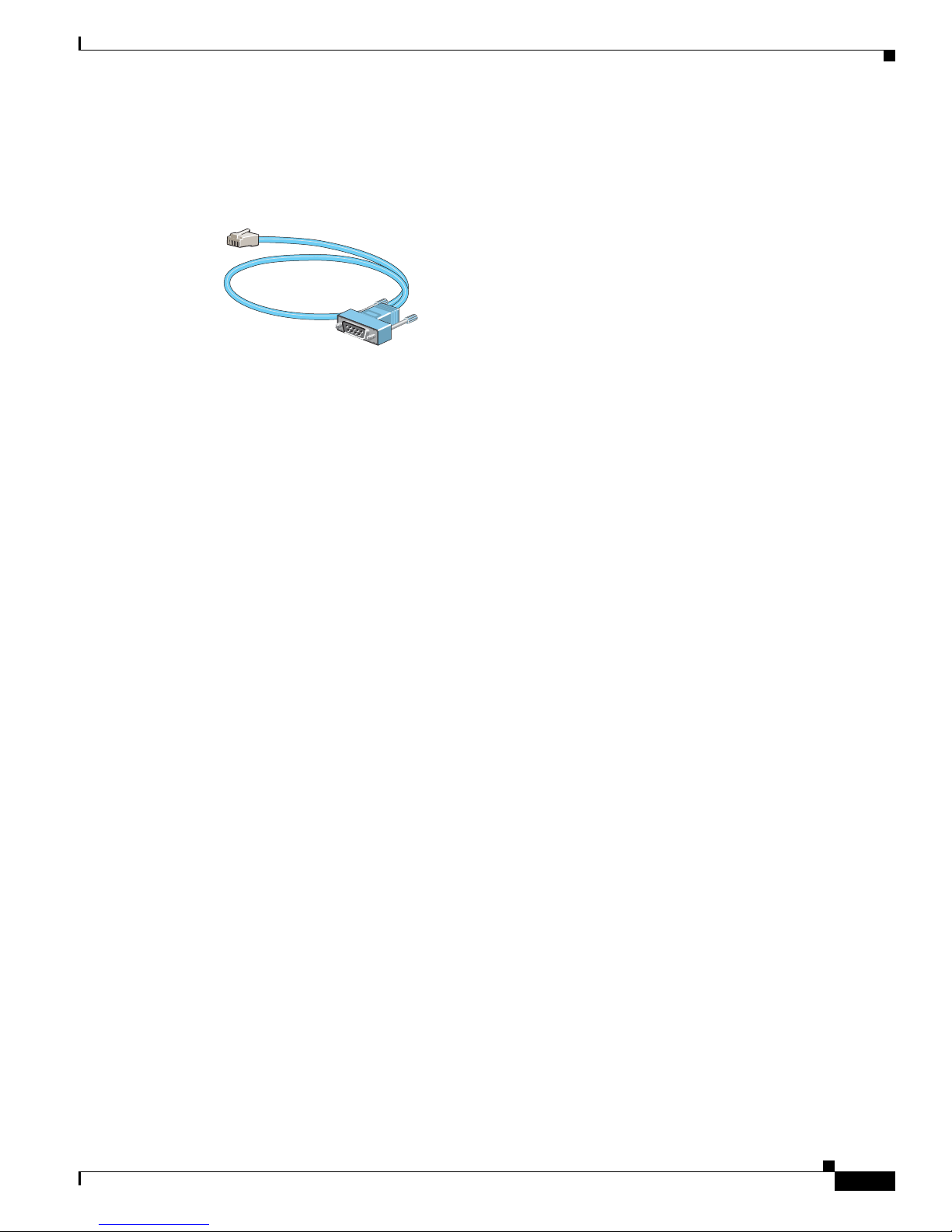
• Cisco Console Cable RJ-45-to-DB9 (Part Number 72-1259-01), as shown in Figure 1
• Product Documentation CD
Figure 1 Cisco Console Cable RJ-45-to-DB9
If you purchased the Option Kit for the switch module and one of these items was not included, contact
your sales representative.
Connecting Devices
This section describes how to connect devices to the switch module and includes the following topics:
Connecting Devices
• Installing and Connecting to Devices in the 10-Gigabit Ethernet Slots, page 3
• Connecting to 10/100/1000 Ports, page 3
• Verifying Port Connectivity, page 4
Installing and Connecting to Devices in the 10-Gigabit Ethernet Slots
The 10-Gb Ethernet module slots on the switch module are used for connections to other switches and
routers.
Use only Cisco-approved SFP+ or SFP modules with the switch module. Each Cisco module has an
internal serial EEPROM that is encoded with security information. This encoding provides a way for
Cisco to identify and validate that the module meets the requirements for the switch module. If the
validation fails, the software will not bring up the port.
Connecting to 10/100/1000 Ports
The External Management Port on the switch module is a 10/100/1000 Ethernet port that uses standard
RJ-45 connectors with Ethernet pinouts. The maximum cable length is 328 feet (100 meters). The
100BASE-TX and 1000BASE-T traffic requires a Category 5, Category 5e, or Category 6 UTP cable.
The 10BASE-T traffic can use a Category 3 or Category 4 cable.
The autonegotiation feature is enabled by default on the External Management Port. At this setting, the
port configures itself to operate at the speed of attached devices. If the attached device does not support
autonegotiation, you can explicitly set the External Management Port speed and the duplex parameters.
To maximize performance, either allow the port to autonegotiate both speed and duplex, or set the port
speed and duplex parameters on both ends of the connection.
OL-19952-02
Cisco Nexus 4001I and 4005I Switch Module for IBM BladeCenter Getting Started Guide
3
Page 4

Configuring the Switch
Send feedback to nexus4K-docfeedback@cisco.com
For simplified cabling, the automatic medium-dependent interface crossover (auto-MDIX) feature is
enabled by default on the External Management Port. With auto-MDIX enabled, the port detects the
required cable type for copper Ethernet connections and configures the interface accordingly. Therefore,
you can use either a crossover or a straight-through cable for connections to the External Management
Port, regardless of the type of device on the other end of the connection.
For more information about enabling or disabling autonegotiation and auto-MDIX, see the Cisco Nexus
4001I and 4005I Switch Module for IBM BladeCenter NX-OS Command Reference and the Cisco Nexus
4001I and 4005I Switch Module for IBM BladeCenter NX-OS Configuration Guide on Cisco.com.
Verifying Port Connectivity
After you connect a device to a switch module port, the port LED is off while the switch module
establishes a link. This process takes about 30 seconds. The LED turns green when the switch module
and the attached device have an established link. If the LED is off, the device might not be turned on,
there might be a cable problem, or there might be a problem with the adapter installed in the device.
Configuring the Switch
This section describes how to configure the switch and includes the following topics:
• Assigning the IP Address on the switch module, page 4
• Initial Setup, page 6
Assigning the IP Address on the switch module
When you first set up the switch module, use the blade enclosure Advanced Management Module
(AMM) to enter the initial IP information. You can then access the switch module through the IP address
for further configuration.
Caution Do not connect devices to the external ports on the switch module until you have completed the setup
procedures and your configuration matches that of the upstream network.
To assign an IP address to the switch module, perform the following steps:
Step 1 Obtain the static IP address and the default gateway address from your system administrator.
Step 2 Establish a connection to the AMM, as described in the IBM BladeCenter Advanced Management
Module User’s Guide. In the login window, enter your User ID and password, and click Log In.
Note AMM refers to the switch module as the I/O module.
Step 3 In the Welcome window, click Continue.
The System Status summary pane appears.
Step 4 In the I/O Module Advanced Setup area, expand I/O Module Tasks and click Admin/Power/Restart (see
Figure 2).
Cisco Nexus 4001I and 4005I Switch Module for IBM BladeCenter Getting Started Guide
4
OL-19952-02
Page 5

Configuring the Switch
Send feedback to nexus4K-docfeedback@cisco.com
Figure 2 AMM I/O Module Admin/Power/Restart Window
Step 5 From the External ports drop-down list, choose Enabled to enable external ports on the switch module.
Step 6 Click Save to save your settings.
Step 7 In the left pane, expand I/O Module Tasks, and click Configuration.
Step 8 In the I/O Module Power/Restart area, check the check box for the bay that corresponds to the location
of the I/O module (switch module) that you are configuring.
Note The switch module can only be installed in Bays 7 through 10.
The applicable bay number appears in the pane, followed by other related I/O-module information,
including the IP address. The I/O-module information is divided into two areas: Current IP
Configuration and New Static IP Configuration (see
Figure 3).
OL-19952-02
Cisco Nexus 4001I and 4005I Switch Module for IBM BladeCenter Getting Started Guide
5
Page 6

Configuring the Switch
Send feedback to nexus4K-docfeedback@cisco.com
Step 9 In the New Static IP Configuration area, enter the new IP address, the Subnet mask, and the Gateway
Figure 3 AMM I/O Module Configuration Window
address. Click Save.
Step 10 Click the Advanced Configuration link. Take the following actions for switch module features:
Step 11 (Optional) To begin a Telnet session to the switch module, click the Start Telnet Session link. Click
Step 12 Click Save to save your settings. Exit the AMM web interface.
Initial Setup
Step 1 Open the AMM and configure the IP address, subnet mask, and gateway address for the management
Note The Save button is located in the lower, right portion of the window.
a. Enable external management for all ports.
b. Preserve the new IP configuration on all resets.
Note These features are disabled, by default.
Start Telnet.
To enter the basic configuration parameters, perform the following steps:
interface (mgmt1), as described in
“Assigning the IP Address on the switch module” section on page 4.
Step 2 Telnet to the mgmt1 IP address and log in using the following (default) user ID and password:
• Login ID is USERID.
• Password is PASSW0RD (the 0 in PASSW0RD is a zero).
You can now configure the switch module.
Cisco Nexus 4001I and 4005I Switch Module for IBM BladeCenter Getting Started Guide
6
OL-19952-02
Page 7

Configuring the Switch
Send feedback to nexus4K-docfeedback@cisco.com
Note Register the switch module device immediately with your supplier. Failure to register may affect
response times for the initial service call. The device must be registered to receive entitled
support services.
Step 3 Enter the basic configuration information.
The following example shows how to start the basic configuration setup:
n4k-8# setup
---- Basic System Configuration Dialog ----
This setup utility will guide you through the basic configuration of
the system. Setup configures only enough connectivity for management
of the system.
*Note: setup is mainly used for configuring the system initially,
when no configuration is present. So setup always assumes system
defaults and not the current system configuration values.
Press Enter at anytime to skip a dialog. Use ctrl-c at anytime
to skip the remaining dialogs.
Step 4 Enter the setup mode by entering yes (or y), as in the following example:
Would you like to enter the basic configuration dialog (yes/no): yes
Step 5 (Optional) Create additional accounts by entering yes (or y), as in the following example (no is the
default):
Create another login account (yes/no) [n]: y
Enter the User login Id: <ID>
Enter the password for "qatest": <
Confirm the password for "qatest": <
Enter the user role [network-operator]: <
password
password
>
role
>
>
Step 6 (Optional) Configure an SNMP community string by entering yes (or y), as in the following example (no
is the default):
Configure read-only SNMP community string (yes/no) [n]: y
SNMP community string: <
Step 7 Enter a name for the switch, as in the following example:
Enter the switch name: ibm-switch-1
Step 8 Configure out-of-band management by entering yes (or y), as in the following example:
Continue with Out-of-band (mgmt0) management configuration? (yes/no) [y]: y
Mgmt0 IPv4 address: 10.10.10.1
Mgmt0 IPv4 netmask: 255.255.255.0
Step 9 Configure the IPv4 default gateway (recommended) by entering yes (or y). Enter the gateway IP address.
Configure the default gateway? (yes/no) [y]:y
string
>
OL-19952-02
Cisco Nexus 4001I and 4005I Switch Module for IBM BladeCenter Getting Started Guide
7
Page 8

Configuring the Switch
Send feedback to nexus4K-docfeedback@cisco.com
Step 10 Enable the Telnet service by entering yes (or y), as in the following example:
Step 11 Enable the SSH service by entering yes (or y), as in the following example (the default is no):
Step 12 Configure the NTP server by entering yes (or y), as in the following example (the default is no):
Step 13 Configure the FCOE service by entering yes (or y), as in the following example (the default is no):
IPv4 address of the default gateway: <
Enable the telnet service? (yes/no) [y]: y
Enable the ssh service? (yes/no) [n]:n
Configure the ntp server? (yes/no) [n]:n
Enable FCOE service? (yes/no) [n]:n
IP address
>
After the prompt for the FCOE service, the configuration appears, as in the following example:
The following configuration will be applied:
username qatest password <user-password> role network-operator
snmp-server community topspin ro
switchname ibm-switch-1
interface mgmt0
ip address 10.10.10.1 255.255.255.0
no shutdown
ip route 0.0.0.0/0 10.10.10.100
telnet server enable
no ssh server enable
Would you like to edit the configuration? (yes/no) [n]:
Use this configuration and save it? (yes/no) [y]: y
Step 14 If you want to make changes to the displayed configuration, enter yes (or y); otherwise accept the default
(no) by pressing Enter.
If you enter yes, the setup utility returns to the beginning of the setup, and repeats each step.
Step 15 Save this configuration by entering yes (or y), as in the following example (the default is no):
Use this configuration and save it? (yes/no) [y]: y
ibm-switch-1 #
If you do not save the configuration at this point, none of your changes are part of the configuration the
next time the device reboots. Saving the configuration also automatically configures the boot variables
for the kickstart and system images.
Note The switch module has two out-of-band management interfaces. The AMM configuration is mgmt1. The
mgmt0 interface must be placed on a different subnet than mgmt1.
Cisco Nexus 4001I and 4005I Switch Module for IBM BladeCenter Getting Started Guide
8
OL-19952-02
Page 9

Send feedback to nexus4K-docfeedback@cisco.com
Managing the Switch
After you complete the initial switch module configuration, use the AMM, the CLI, or other management
options (if available) for further configuration. This section describes the following topics:
• Blade Enclosure Advanced Management Module, page 9
• Command-Line Interface, page 9
• Other Management Options, page 9
Blade Enclosure Advanced Management Module
For standalone switch module units, you can use the AMM to configure and manage the switch module.
See the IBM BladeCenter Advanced Management Module User’s Guide for more information.
Command-Line Interface
You can enter Cisco Nexus-OS commands and parameters using the command-line interface (CLI). You
can access the CLI by connecting your management station directly to the switch module console port
or by using Telnet from a remote management station.
Managing the Switch
For more information about using the CLI, see the Cisco Nexus 4001I and 4005I Switch Module for IBM
BladeCenter NX-OS Command Reference.
To connect to the switch module console port, perform the following steps:
Step 1 Connect a console cable to the front panel serial port and connect an Ethernet cable to the front panel
Ethernet management port.
Step 2 Start a terminal-emulation program on the PC.
Step 3 Configure the PC terminal emulation software for 9600 baud, 8 data bits, no parity, 1 stop bit and no
flow control.
Step 4 Telnet to the switch module by using the console or Ethernet management interface.
Provide the login and password that was configured in Step 3 of the “Initial Setup” section on page 6.
Step 5 Use the CLI to enter commands to configure and manage the switch module.
Other Management Options
You can access the Cisco Management Information Base (MIB) variables through SNMP. The SNMP
system consists of three parts: the SNMP manager, the SNMP agent, and the MIB. You can compile
Cisco MIBs with your network management software. If SNMP is configured on a switch, the SNMP
agent responds to MIB-related queries sent by the network management software.
OL-19952-02
Cisco Nexus 4001I and 4005I Switch Module for IBM BladeCenter Getting Started Guide
9
Page 10

Related Documentation
Send feedback to nexus4K-docfeedback@cisco.com
Related Documentation
For more information about the switch module, see the following documents on http://www.cisco.com:
• Cisco Nexus 4001I and 4005I Switch Module for IBM BladeCenter Hardware Installation Guide
• Regulatory Compliance and Safety Information for the Cisco Nexus 4001I and 4005I Switch Module
for IBM BladeCenter
• Cisco Nexus 4001I and 4005I Switch Module for IBM BladeCenter NX-OS Command Reference
• Cisco Nexus 4001I and 4005I Switch Module for IBM BladeCenter NX-OS Configuration Guide
• Cisco Nexus 4001I and 4005I Switch Module for IBM BladeCenter NX-OS Release Notes
• Cisco NX-OS System Messages Reference
Obtaining Documentation and Submitting a Service Request
For information on obtaining documentation, submitting a service request, and gathering additional
information, see the monthly What’s
revised Cisco
technical documentation, at:
http://www.cisco.com/en/US/docs/general/whatsnew/whatsnew.html
New in Cisco Product Documentation, which also lists all new and
Subscribe to the What’s New in Cisco Product Documentation as a Really Simple Syndication (RSS) feed
and set content to be delivered directly to your desktop using a reader application. The RSS feeds are a free
service and Cisco currently supports RSS
This document is to be used in conjunction with the documents listed in the “Related Documentation” section.
CCDE, CCENT, CCSI, Cisco Eos, Cisco HealthPresence, Cisco IronPort, the Cisco logo, Cisco Lumin, Cisco Nexus, Cisco Nurse Connect,
Cisco
Pulse, Cisco StackPower, Cisco StadiumVision, Cisco TelePresence, Cisco Unified Computing System, Cisco WebEx, DCE, Flip Channels,
Flip for Good, Flip Mino, Flipshare (Design), Flip Ultra, Flip Video, Flip Video (Design), Instant Broadband, and Welcome to the Human Network
are trademarks; Changing the Way We Work, Live, Play, and Learn, Cisco
and Flip Gift Card are service marks; and Access Registrar, Aironet, AllTouch, AsyncOS, Bringing the Meeting To You, Catalyst, CCDA, CCDP,
CCIE, CCIP, CCNA, CCNP, CCSP, CCVP, Cisco, the Cisco
Cisco
Systems Capital, the Cisco Systems logo, Cisco Unity, Collaboration Without Limitation, Continuum, EtherFast, EtherSwitch, Event Center,
Explorer, Fast Step, Follow Me Browsing, FormShare, GainMaker, GigaDrive, HomeLink, iLYNX, Internet Quotient, IOS, iPhone, iQuick Study,
IronPort, the IronPort logo, Laser Link, LightStream, Linksys, MediaTone, MeetingPlace, MeetingPlace Chime Sound, MGX, Networkers,
Networking Academy, Network Registrar, PCNow, PIX, PowerKEY, PowerPanels, PowerTV, PowerTV (Design), PowerVu, Prisma, ProConnect,
ROSA, ScriptShare, SenderBase, SMARTnet, Spectrum Expert, StackWise, The Fastest Way to Increase Your Internet Quotient, TransPath, WebEx,
and the WebEx logo are registered trademarks of Cisco Systems, Inc. and/or its affiliates in the United States and certain other countries.
All other trademarks mentioned in this document or website are the property of their respective owners. The use of the word partner does not imply
a partnership relationship between Cisco and any other company. (0908R)
Any Internet Protocol (IP) addresses used in this document are not intended to be actual addresses. Any examples, command display output, and
figures included in the document are shown for illustrative purposes only. Any use of actual IP addresses in illustrative content is unintentional and
coincidental.
© 2009 Cisco Systems, Inc. All rights reserved.
Ve rs i on 2.0.
Capital, Cisco Capital (Design), Cisco:Financed (Stylized), Cisco Store,
Certified Internetwork Expert logo, Cisco IOS, Cisco Press, Cisco Systems,
Cisco Nexus 4001I and 4005I Switch Module for IBM BladeCenter Getting Started Guide
10
OL-19952-02
 Loading...