

Page 1
Note There are six chassis I/O module bays on the rear panel of the server chassis. The InfiniBand switches
Contents
Cisco M SFS7000E Installation Note:
InfiniBand Blade Switch for the Dell Modular
Server Chassis
This document provides instructions on how to install the Cisco M SFS7000E InfiniBand Switch in the
Dell Modular Server Chassis. The Dell Modular Server Chassis is a system that supports up to sixteen
server modules and up to four InfiniBand switches. You may inst all the InfiniBand switch in one of four
chassis I/O module bays on the rear panel of the server chassis.
are supported in the middle four bays that are connected to Fabrics B and C.
For details about the number , types, and location of the module bays and for additional i nformation about
the entire modular server system, see the documentation for the Dell PowerEdge Servers at
www.support.dell.com.
This publication includes the following sections:
• Safety Overview, page 2
• Parts List, page 3
• Switch Description, page 4
• I/O Module Bays and HCA Expansion Cards, page 5
• Pre-installation Guidelines, pag e 6
• Installing the Cisco M SFS7000E InfiniBand Switch, page 6
• Removing the Cisco M SFS7000E InfiniBand Switch, page 11
• Connecting InfiniBand Cables, page 11
• External LED Specifications, page 14
Americas Headquarters:
Cisco Systems, Inc., 170 West Tasman Drive, San Jose, CA 95134-1706 USA
© 2007 Cisco Systems, Inc. All rights reserved.
Page 2
Safety Overview
• External Network Management Requirements, page 15
• Warning Translation, page 16
• Related Documentation, page 21
• Obtaining Documentation, Obtaining Support, and Security Guidelines, page 22
Safety Overview
Safety warnings appear throughout this publication in procedures that, if performed incorrectly, may
harm you. A warning symbol precedes each warning statement.
Warning
Warning
Warning
Warning
Warning
IMPORTANT SAFETY INSTRUCTIONS
This warning symbol means danger . You are in a situation that could cause bodily injury. Before you
work on any equipment, be aware of the hazards involved with electrical circuitry and be familiar
with standard practices for preventing accidents. Use the statement number provided at the end of
each warning to locate its translation in the translated safety warnings that accompanied this
device.
SAVE THESE INSTRUCTIONS
During this procedure, wear grounding wrist straps to avoid ESD damage to the card. Do not directly
touch the backplane with your hand or any metal tool, or you could shock yourself.
Voltage is present on the ba ckplane when the system is operating. To reduce risk of an electric shock,
keep hands and fingers out of the power supply bays and backplane areas.
Read the installation instructions before connecting the system to the power source.
This unit is intended for installation in restricted access areas. A restricted access area can be
accessed only through the use of a special tool, lock and key, or other means of security.
Statement 1017
Statement 1071
Statement 94
Statement 166
Statement 1004
Warning
Warning
Cisco M SFS7000E Installation Note: InfiniBand Blade Switch for the Dell Modular Server Chassis
2
This equipment must be grounded. Never defeat the ground conductor or operate the equipment in the
absence of a suitably installed ground conductor. Contact the appropriate electrical inspection
authority or an electrician if you are uncertain that suitable grounding is available.
Only trained and qualified personnel should be allowed to install, replace, or service thisequipment.
Statement 1030
Statement 1024
78-18371-01
Page 3
Parts List
Warning
Warning
Warning
Parts List
Ultimate disposal of this product should be handled according to all national laws and regulations.
Statement 1040
Class 1M laser radiation when open. Do not view directly with optical instruments.
Use of controls, adjustments, or performing procedures other than those specified may result in
hazardous radiation exposure.
Statement 1057
Statement 1053
This section describes the parts list. The Cisco M SFS7000E InfiniBand Switch package includes the
following parts:
• One Cisco M SFS7000E InfiniBand Switch
• One document titled Regulatory Compliance and Safety Information for the Cisco M SFS7000E
InfiniBand Blade Switch for the Dell Modular Server Chassis
• One document titled Cisco M SFS7000E Installation Note:
InfiniBand Blade Switch for the Dell Modular Server Chassis
• One warranty card
78-18371-01
Cisco M SFS7000E Installation Note: InfiniBand Blade Switch for the Dell Modular Server Chassis
3
Page 4
Switch Description
Switch Description
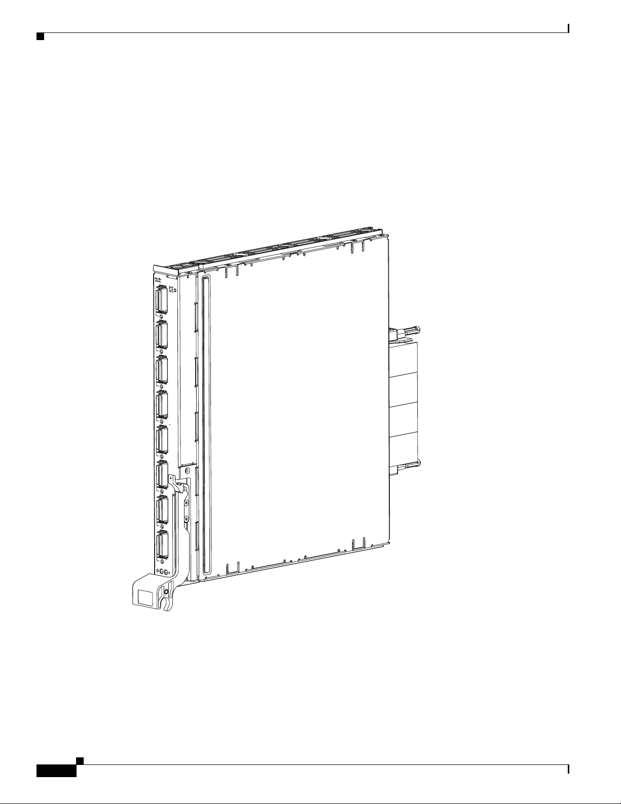
This section describes the Cisco M SFS7000E InfiniBand Switch.
The Cisco M SFS7000E InfiniBand Switch (see Figure 1) connects to the mid-plane of the Dell Modular
Server Chassis and provides user-accessible rear-plane ports. The blade switches are installed in the
system I/O module bays in the rear of the chassis. Each switch has sixteen 4x ports facing the mid-plane
and eight 4x ports facing the exteri or of the chassis. These ports drive Cisco- or Dell-approved DDR IB
cables.
Figure 1 Cisco M SFS7000E InfiniBand Switch
M SFS7000E
TX/RX
TX/
RX
TX/
RX
TX/
RX
TX/
RX
TX/
RX
TX/
RX
250396
TX/
RX
Cisco M SFS7000E Installation Note: InfiniBand Blade Switch for the Dell Modular Server Chassis
4
78-18371-01
Page 5
I/O Module Bays and HCA Expansion Cards
D
185785
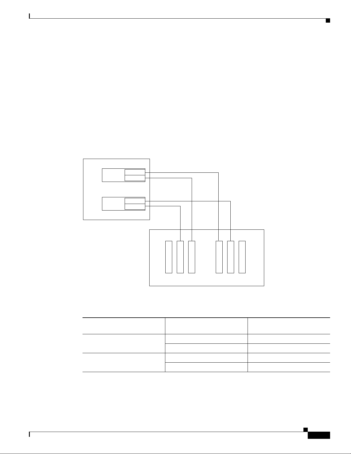
Within the Dell Modular Serv er Chassis un it, blade swi tches mana ge traffic to and from up to two HCA
IB mezzanine cards on the hosts. Each HCA IB mezzanine card adds two IB ports to a host. Each HCA
port connects through the unit mid-plane to a particular blade swi tch slot. The IB ports of the H CA card
that is seated in the HCA B location, connect to I/O module bays B1 and B2. The IB ports of the HCA
card that is seated in the HCA C location, connect to I/O module bays C1 and C2. See Figure 2 and
Table 1 for the location of the HCA cards and the corresponding I/O module bays.
For more details about the location of the HCA IB mezzanine card slots in the Dell Serv er Blade, see the
Dell PowerEdge M600 and M605 Hardware Owners Manual.
.
Figure 2 HCA Mezzanine Card Ports and Corresponding Switch I/O Module Bays
ell Server Blade
I/O Module Bays and HCA Expansion Cards
HCA C
HCA B
Table 1 HCA Mezzanine Card Ports and Corresponding Switch I/O Module Bays
Port 2
Port 1
Port 2
Port 1
B1 C1 C2 B2
Chassis Rear - I/O Module Bays
InfiniBand Switch I/O Module
HCA Mezzanine Card HCA InfiniBand Port
Bay
B1B1
2B2
C1C1
2C2
78-18371-01
Cisco M SFS7000E Installation Note: InfiniBand Blade Switch for the Dell Modular Server Chassis
5
Page 6

Pre-installation Guidelines
Pre-installation Guidelines
This section describes some pre-installation guidelines. Before you begin installation, complete the
following procedures:
• Ground yourself using an approved ground wrist strap.
• Make sure that you have the correct cables.
• Unpack the Cisco M SFS7000E InfiniBand Switch. Remove the packaging from around the switch.
Do not cut the packaging, as you could damage the switch. Save the box and packaging.
Note If you order the switches with the Dell Modular Server Chassis, the switches are already installed, and
no unpacking is required. The unpacking procedure applies only if you order a
Cisco M SFS7000E InfiniBand Switch, separately or without a chassis.
Installing the Cisco M SFS7000E InfiniBand Switch
This section describes how to install the Cisco M SFS7000E InfiniBand Switch.
The Cisco M SFS7000E InfiniBand Switch can be hot-swapped while the Dell 10G system (PowerEdge)
is online. When you install a switch, you do not need to power down the server chassis.
The Cisco M SFS7000E InfiniBand Switch fits into four different bays on the Dell Modular Server
Chassis. These bays connect to either fabric B or C. Each one of th ese fabrics connects to a mezzanine
card on each of the 16 server modules. The HCA is designed to reside in these mezzanine connectors.
T wo swit ches may be used for each fab ric in a non-blocking conf iguration. Multiple fa brics may be used
simultaneously for increased bandwidth.
Note Each bay into which a Cisco M SFS7000E InfiniBand Switch fits must contain either a switch or a blank
input/output module (IOM). When you remove a switch, you must either replace it with an identical
switch or a blank IOM within one minute of removal.
To install the Cisco M SFS7000E InfiniBand Switch in the Dell Modular Server Chassis, perform the
following steps:
Step 1 Select a chassis I/O mod ule bay in which to in stall the swi tch. (See Figure 3 for th e locati on of the I/O
module bays.)
If the HCA IB mezzanine card B is installed, you may install the Cisco M SFS7000E InfiniBand Switch
in I/O slots B1 and/or B2. If the HCA IB mezzanine card C is installed, you may install the
Cisco M SFS7000E InfiniBand Switch in I/O slots C1 and/or C2.
Cisco M SFS7000E Installation Note: InfiniBand Blade Switch for the Dell Modular Server Chassis
6
78-18371-01
Page 7
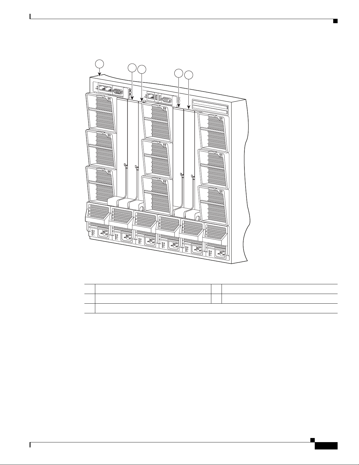
Figure 3 Chassis I/O Module Bays
Installing the CiscoMSFS7000E InfiniBand Switch
1
!
!
!
!
!
2
3
!
!
!
4
5
!
!
!
!
!
!
!
!
!
!
!
!
250401
78-18371-01
1 Dell Modular Server Chassis 2 I/O module B1
3 I/O module C1 4 I/O module C2
5 I/O module B2
Step 2 Remove the IOM blank from the selected bay, if it is present, and store it for future use.
Cisco M SFS7000E Installation Note: InfiniBand Blade Switch for the Dell Modular Server Chassis
7
Page 8

Installing the Cisco MSFS7000E InfiniBand Switch
Connector
Step 3 Remove the connector cover from the switch, and save it for future use. (See Figure 4.)
Figure 4 Removing the Connector Cover
cover
250398
Cisco M SFS7000E Installation Note: InfiniBand Blade Switch for the Dell Modular Server Chassis
8
78-18371-01
Page 9

Installing the CiscoMSFS7000E InfiniBand Switch
Step 4 Press the release latch upward so the switch handle springs open and is perpendicular to the module. (See
Figure 5.)
Figure 5 Switch Handle in Open Position
M SFS7000E
TX/RX
TX/RX
TX/RX
TX/RX
TX/RX
1
TX/RX
2
TX/RX
TX/RX
250397
1 Release latch 2 Switch handle
78-18371-01
Cisco M SFS7000E Installation Note: InfiniBand Blade Switch for the Dell Modular Server Chassis
9
Page 10

Installing the Cisco MSFS7000E InfiniBand Switch
250400
Step 5 Slide the switch completely into the selected bay until it stops, and then rotate the switch handle upward
until it is secured by the release latch.
Figure 6 shows the switch being inserted into the server chassis and the direction in which to rotate the
switch handle to secure it.
Figure 6 Inserting the Switch into the Server Chassis
!
!
M SFS7000E
D
TX/RX
TX/RX
!
TX/RX
TX/RX
TX/RX
!
TX/RX
TX/RX
TX/RX
!
!
!
!
!
!
!
!
!
!
!
!
!
10
Cisco M SFS7000E Installation Note: InfiniBand Blade Switch for the Dell Modular Server Chassis
78-18371-01
Page 11

Removing the Cisco M SFS7000EInfiniBand Switch
Removing the Cisco M SFS7000E InfiniBand Switch
To remove the Cisco M SFS7000E InfiniBand Switch, perform the following steps:
Step 1 Disconnect any cables attached to the Cisco M SFS7000E InfiniBand Switch.
Step 2 Press the release latch upward so the switch handle springs open partially.
Step 3 Rotate the switch handle all the way down to eject the switch.
Step 4 Slide the switch out of the chassis bay.
Step 5 Install the I/O connector cover on the switch.
Note When you remove a switch, you must either replace it with an identical switch or a blank IOM within
one minute of removal.
Connecting InfiniBand Cables
This section describes briefly how to connect your IB cables.
Use IB cables to connect your Cisco M SFS7000E InfiniBand Switch. To plug in an IB cable, push the
connector into the interface. For the pull connector, push the latch until it is engaged after it is in the
interface. An alternative method to plug in a pull connector IB cable is to push the latch first, and then
insert the connector until you hear a click. (See Figure 7 and Figure 8.)
Figure 7 InfiniBand Cable with Pinch Connector
50421
78-18371-01
Cisco M SFS7000E Installation Note: InfiniBand Blade Switch for the Dell Modular Server Chassis
11
Page 12
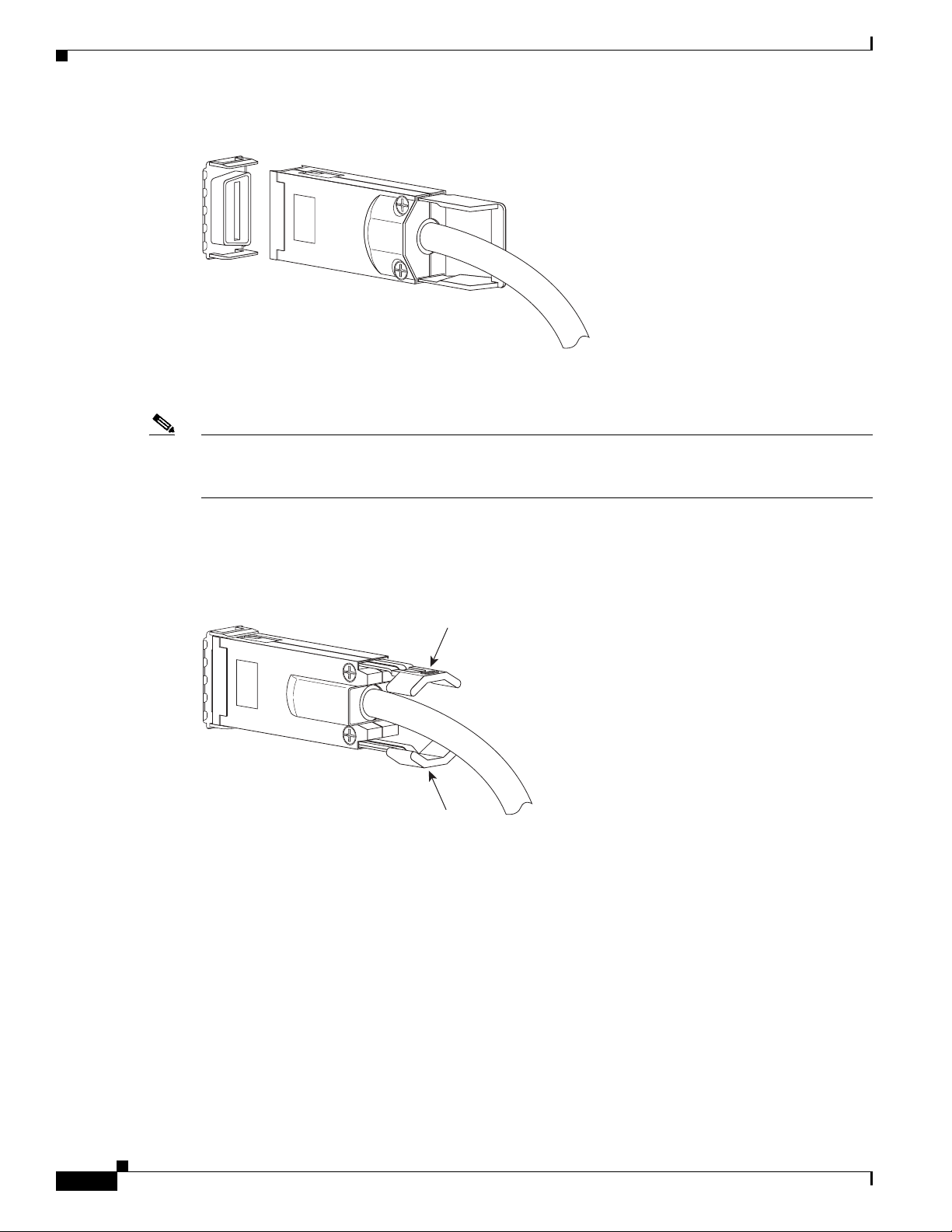
Connecting InfiniBand Cables
Press here
Figure 8 InfiniBand Cable with Pull Connector
Note If the free space around a given IB port is tight, verify that your IB cable connector engages completely.
Wiggle the connector back and forth to be sure that both sides of the connector have locked firmly into
place.
50422
To remove a cable with a pinch connector, pinch both sides of the back of the connector, as shown in
Figure 9, and pull the connector away from the port.
Figure 9 Removing Cable with a Pinch Connector
Press here
50423
12
Cisco M SFS7000E Installation Note: InfiniBand Blade Switch for the Dell Modular Server Chassis
78-18371-01
Page 13

Connecting InfiniBand Cables
Hold here
e
To remove a cable with a pull connector, grasp the connector w ith one hand and push it toward the port,
and then pull the latch away from the port with your other hand while gently wiggling the connector
away from the port, as shown in Figure 10.
Figure 10 Removing Cable with a Pull Connector
Pull her
Hold here
50424
Note The Cisco M SFS7000E InfiniBand Switch also supports optical connections through external
pluggable optical modules.
78-18371-01
Cisco M SFS7000E Installation Note: InfiniBand Blade Switch for the Dell Modular Server Chassis
13
Page 14

External LED Specifications
External LED Specifications
This section describes the external LED specifications for the Cisco M SFS7000E InfiniBand Switch.
Figure 11 LED Indicators on Switch
M SFS7000E
D
1
TX/RX
2
TX/RX
3
TX/RX
4
TX/RX
5
TX/RX
6
TX/RX
7
TX/RX
8
TX/RX
1
2
250399
1 Example of an InfiniBand port status LED 2 Switch status LEDs
14
Cisco M SFS7000E Installation Note: InfiniBand Blade Switch for the Dell Modular Server Chassis
78-18371-01
Page 15

InfiniBand Port Status LEDs
A port status LED indicator (green) exists next to each IB port on the
Cisco M SFS7000E InfiniBand Switch, as shown in Figure 11. Table 2 describes IB port status LED
indicators. The eight ports on the IB switch module are numbered next to each LED indicator.
Table 2 InfiniBand Port Status LED Indicators
LED State Indicators
On (solid) Logical link exists
Blinking Traffic active
Off Link error or Subnet Manager is not running
Switch Status LEDs
Each IB switch module includes two LEDs (one green and one bi-color, blue and amber), as shown in
Figure 11. The power LED and the system status LED provide the overall system status for the
Cisco M SFS7000E InfiniBand Switch and are controlled by the Dell Remote Access
Controller/Modular Chassis (DRAC/MC) management board. The DRAC/MC checks whether or not the
switch blade is valid and has correct identifiers. Table 3 describes the green-colored power LED
indicator. Table 4 describes the bi-colored system status LED indicator.
External Network Management Requirements
Table 3 Switch Status Power LED Indicator
LED States Indicators
On Power is on
Off Powe r i s off
Table 4 System Status LED Indicator
LED States Indicators
Blue off Switch is not ready
Blue blinking Identify
Blue solid on Switch is on and operating normally
Amber blinking Indicates fault
Amber solid on Indicates fault
External Network Management Requirements
You can manage the Cisco M SFS7000E InfiniBand Switch in an InfiniBand network by using the Cisco
High-Performance Subnet Manager or the Cisco Embedded Subnet Manager.
78-18371-01
Cisco M SFS7000E Installation Note: InfiniBand Blade Switch for the Dell Modular Server Chassis
15
Page 16

Warning Translation
Warning Translation
This section repeats, in multiple languages, the basic warning appropriate for the
Cisco M SFS7000E InfiniBand Switch. See the Regulatory Compliance and Safety Information for the
Cisco M SFS7000E InfiniBand Blade Switch for the Dell Modular Server Chassis document for
translations of all warning messages associated with this switch.
Statement 1071—Warning Definition
Warning
Waarschuwing
Varoitus
IMPORTANT SAFETY INSTRUCTIONS
This warning symbol means danger. You are in a situation tha t could cause bod ily injury. Before you
work on any equipment, be aware of the hazards involved with electrical circuitry and be familiar
with standard practices for preventing accidents. Use the statement number provided at the end of
each warning to locate its translation in the translated safety warnings that accompanied this
device.
SAVE THESE INSTRUCTIONS
BELANGRIJKE VEILIGHEIDSINSTRUCTIES
Dit waarschuwingssymbool betekent gevaar. U verkeert in een situatie die lichamelijk letsel kan
veroorzaken. Voordat u aan enige apparatuur gaat werken, dient u zich bewust te zijn van de bij
elektrische schakelingen betrokken risico's en dient u op de hoogte te zijn van de standaard
praktijken om ongelukken te voorkomen. Gebruik het nummer van de verklaring onderaan de
waarschuwing als u een vertaling van de waarschuwing die bij het apparaat wordt geleverd, wilt
raadplegen.
BEWAAR DEZE INSTRUCTIES
TÄRKEITÄ TURVALLISUUSOHJEITA
Tämä varoitusmerkki merkitsee vaaraa. Tilanne voi aiheuttaa ruumiillisia vammoja. Ennen kuin
käsittelet laitteistoa, huomioi sähköpiirien käsittelemiseen liittyvät riskit ja tutustu
onnettomuuksien yleisiin ehkäisytapoihin. Turvallisuusvaroitusten käännökset löytyvät laitteen
mukana toimitettujen käännettyjen turvallisuusvaroitusten joukosta varoitusten lopussa näkyvien
lausuntonumeroiden avulla.
16
SÄILYTÄ NÄMÄ OHJEET
Attention
Cisco M SFS7000E Installation Note: InfiniBand Blade Switch for the Dell Modular Server Chassis
IMPORTANTES INFORMATIONS DE SÉCURITÉ
Ce symbole d'avertissement indique un danger. Vous vous trouvez dans une situation pouvant
entraîner des blessures ou des dommages corporels. Avant de travailler sur un équipement, soyez
conscient des dangers liés aux circuits électriques et familiarisez-vous avec les procédures
couramment utilisées pour éviter les accidents. Pour prendre connaissance des traductions des
avertissements figurant dans les consignes de sécurité traduites qui accompagnent cet appareil,
référez-vous au numéro de l'instruction situé à la fin de chaque avertissement.
CONSERVEZ CES INFORMATIONS
78-18371-01
Page 17

Warning Translation
Warnung
Avvertenza
Advarsel
WICHTIGE SICHERHEITSHINWEISE
Dieses Warnsymbol bedeutet Gefahr . Sie be finden sich in einer Situation, die zu V erletzungen führen
kann. Machen Sie sich vor der Arbeit mit Geräten mit den Gefahren elektrischer Schaltungen und
den üblichen Verfahren zur Vorbeugung vor Unfällen vertraut. Suchen Sie mit der am Ende jeder
Warnung angegebenen Anweisungsnummer nach der jeweiligen Übersetzung in den übersetzten
Sicherheitshinweisen, die zusammen mit diesem Gerät ausgeliefert wurden.
BEWAHREN SIE DIESE HINWEISE GUT AUF.
IMPORTANTI ISTRUZIONI SULLA SICUREZZA
Questo simbolo di avvertenza indica un pericolo. La situazione potrebbe causare infortuni alle
persone. Prima di intervenire su qualsiasi apparecchiatura, occorre essere al corrente dei pericoli
relativi ai circuiti elettrici e conoscere le procedure standard per la prevenzione di incidenti.
Utilizzare il numero di istruzione presente alla fine di ciascuna avvertenza per individuare le
traduzioni delle avvertenze riportate in questo documento.
CONSERVARE QUESTE ISTRUZIONI
VIKTIGE SIKKERHETSINSTRUKSJONER
Dette advarselssymbolet betyr fare. Du er i en situasjon som kan føre til skade på person. Før du
begynner å arbeide med noe av utstyret, må du være oppmerksom på farene forbundet med
elektriske kretser , og kjenn e til standardprosedyrer for å forhindre u lykker. Bruk nummeret i slutten
av hver advarsel for å finne oversettelsen i de oversatte sikkerhetsadvarslene som fulgte med denne
enheten.
Aviso
¡Advertencia!
TA VARE PÅ DISSE INSTRUKSJONENE
INSTRUÇÕES IMPORTANTES DE SEGURANÇA
Este símbolo de aviso significa perigo. Você está em uma situação que poderá ser causadora de
lesões corporais. Antes de iniciar a utilização de qualquer equipamento, tenha conhecimento dos
perigos envolvidos no manuseio de circuitos elétricos e familiarize-se com as práticas habituais de
prevenção de acidentes. Utilize o número da instrução fornecido ao final de cada aviso para
localizar sua tradução nos avisos de segurança traduzidos que acompanham este dispositivo.
GUARDE ESTAS INSTRUÇÕES
INSTRUCCIONES IMPORTANTES DE SEGURIDAD
Este símbolo de aviso indica peligro. Existe riesgo para su integridad física. Antes de manipular
cualquier equipo, considere los riesgos de la corriente eléctrica y familiarícese con los
procedimientos estándar de prevención de accidentes. Al final de cada advertencia encontrará el
número que le ayudará a encontrar el texto traducido en el apartado de traducciones que acompaña
a este dispositivo.
GUARDE ESTAS INSTRUCCIONES
78-18371-01
Cisco M SFS7000E Installation Note: InfiniBand Blade Switch for the Dell Modular Server Chassis
17
Page 18

Warning Translation
Varning!
VIKTIGA SÄKERHETSANVISNINGAR
Denna varningssignal signalerar fara. Du befinner dig i en situation som kan leda till personskada.
Innan du utför arbete på någon utrustning måste du vara medveten om farorna med elkretsar och
känna till vanliga förfaranden för att förebygga olyckor. Använd det nummer som finns i slutet av
varje varning för att hitta dess översättning i de översatta säkerhetsvarningar som medföljer denna
anordning.
SPARA DESSA ANVISNINGAR
18
Cisco M SFS7000E Installation Note: InfiniBand Blade Switch for the Dell Modular Server Chassis
78-18371-01
Page 19

Warning Translation
Aviso
Advarsel
INSTRUÇÕES IMPORTANTES DE SEGURANÇA
Este símbolo de aviso significa perigo. Você se encontra em uma situação em que há risco de lesões
corporais. Antes de trabalhar com qualquer equipamento, esteja ciente dos riscos que envolvem os
circuitos elétricos e familiarize-se com as práticas padrão de prevenção de acidentes. Use o
número da declaração fornecido ao final de cada aviso para localizar sua tradução nos avisos de
segurança traduzidos que acompanham o dispositivo.
GUARDE ESTAS INSTRUÇÕES
VIGTIGE SIKKERHEDSANVISNINGER
Dette advarselssymbol betyder fare. Du befinder dig i en situation med risiko for
legemesbeskadigelse. Før du begynder arbejde på udstyr, skal du være opmærksom på de
involverede risici, der er ved elektriske kredsløb, og du skal sætte dig ind i standardprocedurer til
undgåelse af ulykker. Brug erklæringsnummeret efter hver advarsel for at finde oversættelsen i de
oversatte advarsler, der fulgte med denne enhed.
GEM DISSE ANVISNINGER
78-18371-01
Cisco M SFS7000E Installation Note: InfiniBand Blade Switch for the Dell Modular Server Chassis
19
Page 20

Warning Translation
20
Cisco M SFS7000E Installation Note: InfiniBand Blade Switch for the Dell Modular Server Chassis
78-18371-01
Page 21

Related Documentation
Related Documentation
For additional information related to the Cisco M SFS7000E InfiniBand Switch, see the following
documents:
• Regulatory Compliance an d Safety Informat ion for the Cisco M SFS700 0E Infi niBand Blade Switch
for the Dell Modular Server Chassis
• Dell Remote Access Controller/Modular Chassis User's Guide
• Dell PowerEdge M600 and M605 Hardware Owners Manual
Cisco M SFS7000E Installation Note: InfiniBand Blade Switch for the Dell Modular Server Chassis
78-18371-01
21
Page 22

Obtaining Documentation, Obtaining Support, and Security Guidelines
Obtaining Documentation, Obtaining Support, and Security
Guidelines
For information on obtaining documentation, obtaining support, providing documentation feedback,
security guidelines, and also recommended aliases and general Cisco documents, see the monthly
What’s New in Cisco Product Documentation, which also lists all new and revised Cisco technical
documentation, at:
http://www.cisco.com/en/US/docs/general/wha tsnew/whatsnew.html
This document is to be used in conjunction with the documents listed in the “Related Documentation” section.
CCVP, the Cisco logo, and Welcome to the Human Network are trademarks of Cisco Systems, Inc.; Changing the Way We Work, Live, Play, and Learn is
a service mark of Cisco Systems, Inc.; and Access Registrar, Aironet, Catalyst, CCDA, CCDP, CCIE, CCIP, CCNA, CCNP, CCSP, Cisco, the Cisco
Certified Internetwork Expert logo, Cisco IOS, Cisco Press, Cisco Systems, Cisco Systems Capital, the Cisco Systems logo, Cisco Unity,
Enterprise/Solver, EtherChannel, EtherFast, EtherSwitch, Fast Step, Follow Me Browsing, FormShare, GigaDrive, HomeLink, Internet Quotient, IOS,
iPhone, IP/TV, iQ Expertise, the iQ logo, iQ Net Readiness Scorecard, iQuick Study, LightStream, Linksys, MeetingPlace, MGX, Networkers,
Networking Academy, Network Registrar, PIX, ProConnect, ScriptShare, SMARTnet, StackWise, The Fastest Way to Increase Your Internet Quotient,
and TransPath are registered trademarks of Cisco Systems, Inc. and/or its affiliates in the United States and certain other countries.
All other trademarks mentioned in this document or Website are the property of their respective owners. The use of the word partner does not imply a
partnership relationship between Cisco and any other company. (0711R)
Any Internet Protocol (IP) addresses used in this document are not intended to be actual addresses. Any examples, command display output, and
figures included in the document are shown for illustrative purposes only. Any use of actual IP addresses in illustrative content is unintentional and
coincidental.
© 2007 Cisco Systems, Inc. All rights reserved.
Printed in the USA on recycled paper containing 10% postconsumer waste.
22
Cisco M SFS7000E Installation Note: InfiniBand Blade Switch for the Dell Modular Server Chassis
78-18371-01
 Loading...