

Page 1
Send documentation comments to mdsfeedback-doc@cisco.com.
Technical Specifications
This appendix includes the following technical specifications for the Cisco MDS 9020 Fabric Switch:
• Switch Specifications, page C-1
• Power Specifications, page C-2
• Supported Power Cords and Plugs, page C-3
Switch Specifications
Table C-1 lists the environmental specifications for the Cisco MDS 9020 Fabric Switch. Table C-2 lists
the switch specifications for the C isco MDS 9 020 Fabric Sw itch.
Table C-1 Environmental Specifications for the Cisco MDS 9020 Fabric Switch
APPENDIX
C
Description Specification
Temperature, ambient operating 41 to 104°F (5 to 40°C)
Temperature, ambient nonoperating and storage - 40 to 158°F (- 40 to 70°C)
Humidity (RH), ambient (noncondensing)
operating
Humidity (RH), ambient (noncondensing)
nonoperating and storage
Altitude, operating 0 to 10,000 ft (0 to 2000 m)
Table C-2 Cisco MDS 9020 Fabric Switch Specifications
Description Specification
Dimensions Width = 17 in. (43.2 cm)
Rack unit (RU) Chassis requires 1 RU (1.75 in. or 4.45 cm)
We ight 9 lb
Airflow Front-to-back
5 to 90%
5 to 93%
Height = 1.70 in. (4.32 cm)
Depth = 12.0 in. (30.5 cm)
OL-6987-01
Cisco MDS 9020 Fabric Switch Hardware Installation Guide
C-1
Page 2
Appendix C Technical Specifications
Power Specifications
Send documentation comments to mdsfeedback-doc@cisco.com.
Power Specifications
This section includes the following information:
• General Power Supply Specifications, pa ge C-2
• Power Supply Requirements and Heat Dissipation Specifications, page C-2
• Connection Guidelines for AC-Powered Systems, page C-3
General Power Supply Specifications
Table C-3 lists the specifications for the Cisco MDS 9020 Fabric Switch AC input power supply.
Table C-3 Cisco MDS 9020 Fabric AC Input Power Supply Specifications
AC-Input Power Supply Specification
AC-input voltage 100 to 240 VAC; 50 to 60 Hz
AC-input current rating (maximum) 1 A at 120 VAC
0.5 A at 240 VAC
AC-input frequency 50 to 60 Hz
Power supply output capacity 100 Wa tts
Power supply output voltage 3, 5, and 12 VDC
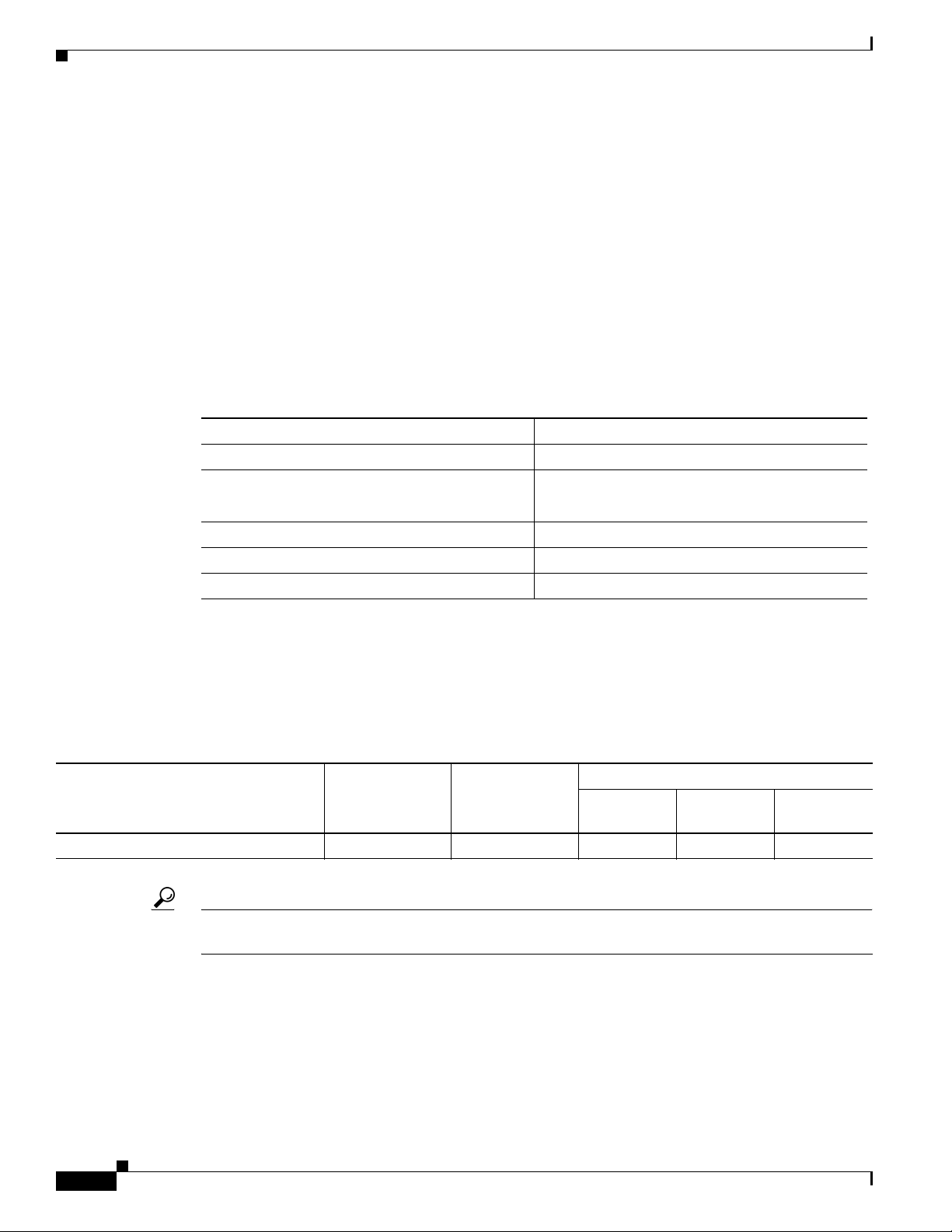
Power Supply Requirements and Heat Dissipation Specifications
Table C-4 provides a sample calculation of power and heat dissipation for the Cisco MDS 9020 Fabric
Switch.
Table C-4 Power and Heat Dissipation
Input Current
AC-Input Power
Model Number
Cisco MDS 9020 Fabric 100 341 1.2 0.90 0.45
Tip T o pre v ent a loss of input power, ensure the total maximum load on each circuit supplying the switch
is within the current ratings of the wiring and breakers.
(watts)
Heat Dissipation
(BTU/Hr.)
85 VAC
(amps)
110 VAC
(amps)
220 VAC
(amps)
C-2
Cisco MDS 9020 Fabric Switch Hardware Installation Guide
OL-6987-01
Page 3

Appendix C Technical Specifications
Supported Power Cords and Plugs
Send documentation comments to mdsfeedback-doc@cisco.com.
Connection Guidelines for AC-Powered Systems
Follow these basic guidelines for connecting the Cisco MDS 9020 Fabric Switch AC power supply to
the site power source.
• For international, circuits should be sized according to local and national codes.
• The AC power receptacles used to plug in the chassis must be the grounding type. The grounding
conductors that connect to the receptacles should connect to protective earth ground at the service
equipment.
Supported Power Cords and Plugs
A separate power cord is provided for each power supply. Standard power cords or jumper power cords
are available for connection to a power distribution unit having IEC 60320 C13 outlet receptacles. The
jumper power cords, for use in cabinets, are available as an option instead of the standard power cords.
OL-6987-01
Cisco MDS 9020 Fabric Switch Hardware Installation Guide
C-3
Page 4

Appendix C Technical Specifications
Supported Power Cords and Plugs
Send documentation comments to mdsfeedback-doc@cisco.com.
Power Cords
The standard power cords hav e an IEC C15 connector on the end that plugs in to the switch. The optional
jumper power cords have an IEC C15 connector on the end that plugs into the switch, and an IEC C14
connector on the end that plugs into an IEC C13 outlet receptacle.
Note Only the standard power cords or jumper power cords provided with the switch are supported.
Figure C-1 shows the supported plugs for the Cisco MDS 9020 Fabric Switch.
Figure C-1 Power Supply Plugs
1 2
3 4
5 6
7
8
1 Argentina
IRAM 2073 plug (10A)
2 North America
NEMA 5-15P plug (15A)
3 Australia, New Zealand
SAA/3 plug, AS/NZS 3112-1993 (10A)
4 Europe
VIIG Plug, CEE (7) VII (16A)
99271
5 Italy
1/3G plug, CEI 23-16 (10A)
6 United Kingdom
BS89/13, BS 1363/A
(13A; replaceable fuse)
7 South Africa
EL 208, SABS 164-1 (10A)
8 Switzerland
12G SEV 1011 (10A)
C-4
Cisco MDS 9020 Fabric Switch Hardware Installation Guide
OL-6987-01
Page 5

Appendix C Technical Specifications
113165
Supported Power Cords and Plugs
Send documentation comments to mdsfeedback-doc@cisco.com.
Jumper Power Cord
Figure C-2 shows the C14 and C15 connectors on the optional jumper power cord for the Cisco MDS
9020 Fabric Switch. The C15 connector connects into the C14 inlet on the Cisco MDS 9020 Fabric
Switch, while the C14 connector connects into the C13 receptacle of a power distribution unit for a
cabinet.
Figure C-2 Connectors on Jumper Power Cord for Cisco MDS 9020 Series
C15
C14
1 C14 and C15 Connectors on Jumper Power
Cord for Cisco 9100 Series
Power Cord Product ID: CAB-C15-CBN
250 VAC 13A, C14-C15 Connectors
OL-6987-01
Cisco MDS 9020 Fabric Switch Hardware Installation Guide
C-5
Page 6

Appendix C Technical Specifications
Supported Power Cords and Plugs
Send documentation comments to mdsfeedback-doc@cisco.com.
C-6
Cisco MDS 9020 Fabric Switch Hardware Installation Guide
OL-6987-01
 Loading...