

Page 1
Cisco MCS 7890-C1 Business Edition 3000
Appliance User Guide
Published: November 4, 2011
This document contains brief, concise instructions that tell you how to install the MCS 7890-C1 quickly.
This document includes the following topics:
• Before You Begin, page 1
• Unpacking the MCS 7890-C1, page 2
• Mounting the MCS 7890-C1, page 4
• Connecting the MCS 7890-C1, page 6
• Starting the MCS 7890-C1, page 9
Before You Begin
The Cisco MCS 7890-C1 is an easy-to-manage, purpose-built appliance that integrates the benefits of
media processing (for voice calling and mobility) and digital circuit gateway functionality on a single
system. Consolidating these functions creates a cost-effective solution that is simple to set up, manage,
and use, thereby lowering total cost of ownership and providing a smooth migration from older, outdated
telephony systems to IP communications.
Designed for midmarket organizations with smaller IT staffs, the solution provides investment protection
with the capacity to grow to up to 300 employees (400 endpoints) and ten total sites (nine remote sites).
The Cisco MCS 7890-C1 comes preinstalled with the Cisco Business Edition 3000 software, integrated
dual T1/E1 public-switched-telephone-network (PSTN) interfaces, and an easy-to-use administration
and provisioning interface.
Cisco supplies the MCS 7890-C1 in a single package that contains the items that are listed in the
Unpacking the MCS 7890-C1 section. Make sure all of the parts are in the package. Never use defective
parts. Never replace a part that is listed in the Unpacking the MCS 7890-C1 section with a different type
of part. If any item that is listed in the Unpacking the MCS 7890-C1 section is damaged or missing,
contact your Cisco representative at your earliest convenience.
Americas Headquarters:
Cisco Systems, Inc., 170 West Tasman Drive, San Jose, CA 95134-1706 USA
© 2011 Cisco Systems, Inc. All rights reserved.
Page 2
Unpacking the MCS 7890-C1
In addition to the items that are listed in the Unpacking the MCS 7890-C1 section, you need to have the
following things to install the MCS 7890-C1:
• Phillips screwdriver
• 19-inch rack (for rack-mounting)
• Wall (for wall-mounting)
• Scratch awl or other sharp pointed object (for wall-mounting)
• Electric drill with a 0.3-inch-diameter (7.5-mm-diameter) drill bit (for wall-mounting)
Warning
Installation of the equipment must comply with local and national electrical codes.
Unpacking the MCS 7890-C1
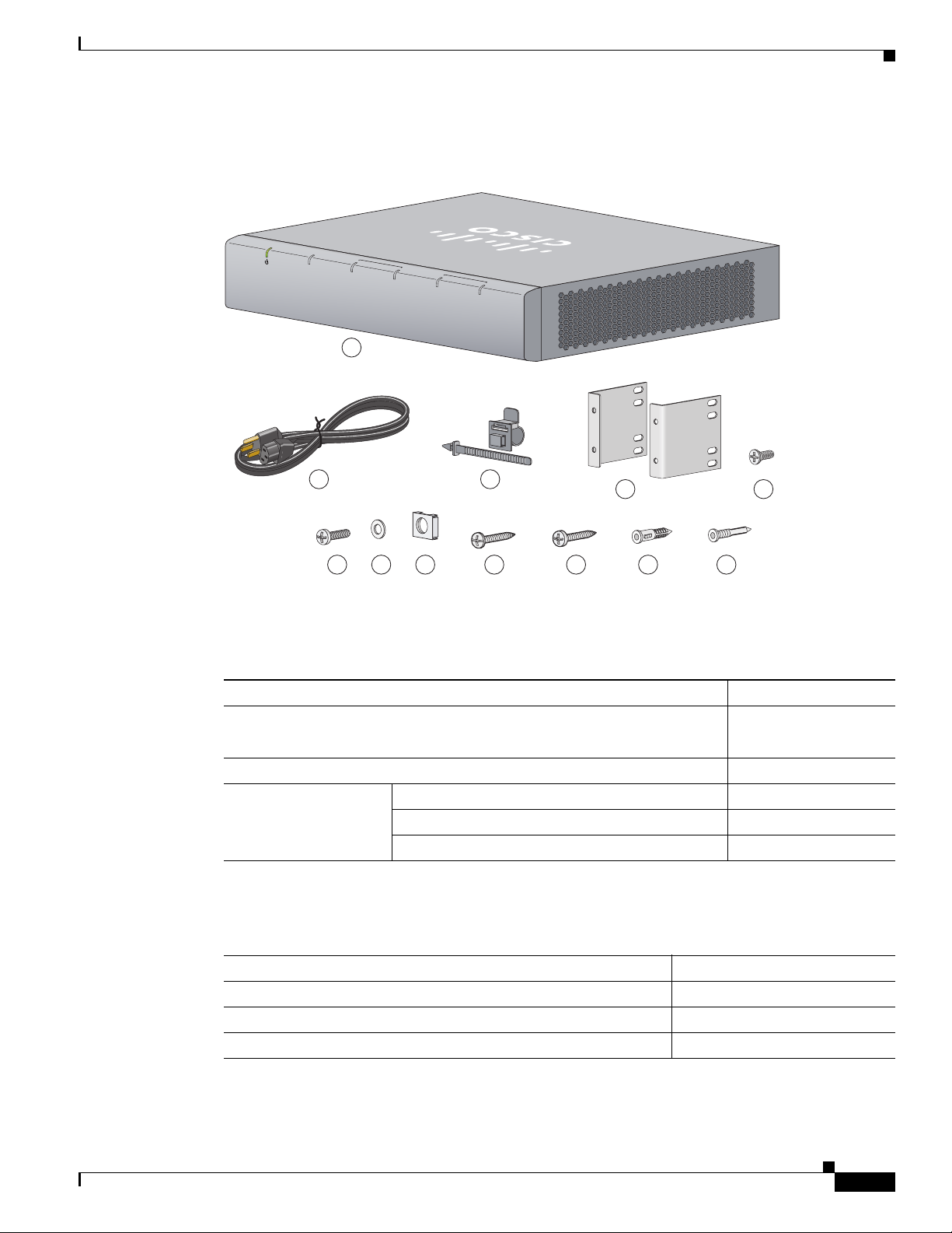
The MCS 7890-C1 package includes the following components:
• MCS 7890-C1
• Accessory kit
• Rack-mounting kit
• Wall-mounting kit
Table 1 lists the items in the MCS 7890-C1 accessory kit.
Table 1 Accessory Kit Contents
Description Quantity
RJ-45 to RJ-45 Ethernet cable 1
Power cable retainer 1
Removable USB flash drive (4 GB) 1
Removable USB flash drive key (8 GB) 1
Cable management tie wrap 1
Rack-mounting kit (see Table 2 on page 3)1
Wall-mounting kit (see Table 3 on page 3)1
Wire mounts 2
Screws for wire mount 2
Cable mounts 2
CD/DVD containing documentation, RCSI
information, and warranty
Cisco Business Edition 3000 software DVD 1
1
Note The power cable is not included in the accessory kit. Customers place their order for a
country-specific power cable when they place their order for the MCS 7890-C1.
Cisco MCS 7890-C1 Business Edition 3000 Appliance User Guide
2
OL-25101-02
Page 3
255497
POWER
SYSTEM
CONNECTION
ALARM
T1/E1 1
CONNECTION
ALARM
T1/E1 0
1
4
2
5
9 11 12107 86
3
Figure 1 MCS 7890-C1 Equipment
Unpacking the MCS 7890-C1
Table 2 lists the items in the MCS 7890-C1 rack-mounting kit.
Table 2 Rack-Mounting Kit Contents
Description Quantity
Rack mount brackets (see item no. 4 in Figure 1)2
Screw: M4, L8, Phillips head (see item no. 5 in Figure 1)4
Screw kit Cage nut (see item no. 8 in Figure 1)4
Screw (see item no. 6 in Figure 1)4
Plastic washer (see item no. 7 in Figure 1)4
Table 3 on page 3 lists the items in the MCS 7890-C1 wall-mounting kit.
Table 3 Wall-Mounting Kit Contents
Description Quantity
General tapping screw (see item no. 10 in Figure 1 on page 3)4
General plastic anchor (see item no. 11 in Figure 1 on page 3)4
Drywall tapping screw (see item no. 9 in Figure 1 on page 3)4
OL-25101-02
Cisco MCS 7890-C1 Business Edition 3000 Appliance User Guide
3
Page 4

Mounting the MCS 7890-C1
Table 3 Wall-Mounting Kit Contents (continued)
Description Quantity
Drywall plastic anchor (see item no. 12 in Figure 1 on page 3)4
Wall-mounting template 1
1
CABLE SIDE ENTRY
THIS SIDE AWAY FROM MOUNTING SURFACE
Mounting the MCS 7890-C1
This section includes the following MCS 7890-C1 topics:
• Rack-Mounting
• Wall-Mounting, page 6
Rack-Mounting
Perform the following procedure to mount the MCS 7890-C1 in a 19-inch rack. You use items from the
rack-mounting kit described in Table 2 on page 3.
Procedure
2
255498
Step 1 Use screws to attach the rack-mount brackets to the left and right sides of the MCS 7890-C1 as Figure 2
on page 4 shows.
Figure 2 Attaching Rack-Mount Brackets to the MCS 7890-C1
T1/E1 1
T1/E1 2
255499
Cisco MCS 7890-C1 Business Edition 3000 Appliance User Guide
4
OL-25101-02
Page 5

Mounting the MCS 7890-C1
255500
POWER
SYSTEM
CONNECTION
ALARM
T1/E1 1
CONNECTION
ALARM
T1/E1 0
2
1
255501
CONNECTION
ALARM
T1/E1 0
Step 2 On the brackets you attached in Step 1, choose which pairs of holes you want to use. As Figure 3 shows,
you can choose either top holes (Type 1) or bottom holes (Type 2). Use Type 1 holes if you want to align
the MCS 7890-C1 under the bottom of other equipment in the rack. Use Type 2 holes if you want to align
the MCS 7890-C1 over the top of other equipment in the rack.
Figure 3 Hole Types
Step 3
Attach the MCS 7890-C1 to the 19-inch rack by using the contents of the screw kit (cage nut, screw, and
plastic washer) through the four holes you choose to use as shown in Figure 4 on page 5.
Figure 4 Using the Screw Kit Contents
OL-25101-02
Cisco MCS 7890-C1 Business Edition 3000 Appliance User Guide
5
Page 6

Connecting the MCS 7890-C1
Wall-Mounting
Perform the following procedure to mount the MCS 7890-C1. You use items from the wall-mounting kit
described in Table 3 on page 3.
Procedure
Step 1 Take the wall-mounting template and temporarily attach it to the wall on which you want to mount the
MCS 7890-C1. Attach the template to the wall so that the image of the MCS 7890-C1 appears in the
exact place where you want to mount the MCS 7890-C1.
Step 2 Locate the four dark circles on the wall-mounting template. Locate the lines that intersect inside these
dark circles. At each point where the lines intersect inside these dark circles, use a scratch awl or other
sharp pointed object to punch a hole through the wall-mounting template to mark the spot on the wall
where you want to drill a hole for a mounting screw.
Step 3 Remove the wall-mounting template from the wall. At each of the four spots you marked in Step 2, drill
a hole with a 0.3-inch-diameter (7.5-mm-diameter) drill bit. Drill each hole at least 1.37 in. (35 mm)
deep.
Step 4 Into each hole that you drilled in Step 3, insert a plastic anchor so that the opening of the anchor is flush
with the wall surface.
Step 5 Into each plastic anchor that you inserted in Step 4, insert a tapping screw. Screw in the tapping screw
so that there is 0.09 inches (1.5 mm) of space between the wall and the back of the screw head.
Step 6 Hang the MCS 7890-C1 on the wall. To do this, perform the following procedure:
a. Hold the MCS 7890-C1 in both of your hands with the Cisco logo facing you and the MCS 7890-C1
LEDs along the bottom edge.
b. Approach the wall that you inserted the tapping screws into.
c. Align the tapping screws with the round holes in the back of the MCS 7890-C1. Press the
MCS 7890-C1 toward the wall so that the heads of the tapping screws enter the round holes.
d. Move the MCS 7890-C1 slowly down the wall. Allow the MCS 7890-C1 to come to rest securely on
the tapping screws.
Connecting the MCS 7890-C1
Figure 5 on page 7 shows the various ports on the back panel of the MCS 7890-C1. See Table 4 on page 7
for descriptions of each of the numbers.
Cisco MCS 7890-C1 Business Edition 3000 Appliance User Guide
6
OL-25101-02
Page 7

Figure 5 MCS 7890-C1 Back Panel
Connecting the MCS 7890-C1
T1/E1 1
1
T1/E1 2
2
5
3
4
7
6
8
9
Table 4 MCS 7890-C1 Back Panel
# Description
1 T1/E1 interface
2 T1/E1 interface
3 Audio line-in interface
4 USB (use for keyboard, mouse and USB dongle)
5 RJ45 interface
6 USB (use for keyboard, mouse and USB dongle)
7 DB-9 console/auxiliary interface or console port
8 VGA interface
9 Fan with grill
10 Back panel power switch (there is also a front
panel power button)
11 AC power connector
10
255502
11
OL-25101-02
Use the power cable retainer (1) to prevent the accidental removal of the power cable (2), as shown in
Figure 6 on page 8.
Cisco MCS 7890-C1 Business Edition 3000 Appliance User Guide
7
Page 8

Connecting the MCS 7890-C1
Figure 6 Power Cable Retainer
1
2
255503
Screw the wire mounts onto the back wall of the MCS 7890-C1, then lace the cables into the wire
mounts, as shown in Figure 7.
Figure 7 Wire Mounts
T1/E1 1
T1/E1 2
T1/E1 1
T1/E1 2
255504
Finally, wrap the cables together using the cable management tie wrap (1), as shown in Figure 8.
Figure 8 Cable Management Tie Wrap
1
T1/E1 1
Cisco MCS 7890-C1 Business Edition 3000 Appliance User Guide
8
T1/E1 2
255497
255505
OL-25101-02
Page 9

Starting the MCS 7890-C1
Warning
Warning
Warning
Warning
Warning
For connections outside the building where the equipment is installed, the following ports must be
connected through an approved network termination unit with integral circuit protection: E1/T1
This product requires short-circuit (overcurrent) protection, to be provided as part of the building
installation. Install only in accordance with national and local wiring regulations.
The plug-socket combination must be accessible at all times, because it serves as the main
disconnecting device.
This equipment must be grounded. Never detach the ground conductor or operate the equipment in the
absence of a suitably installed ground conductor. Contact the appropriate electrical inspection
authority or an electrician if you are uncertain that suitable grounding is available.
When installing the product, use the provided or designated connection cables/power cables/AC
adaptors/batteries. Using any other cables/adaptors could cause a malfunction or a fire. Electrical
Appliance and Material Safety Law prohibits the use of UL-certified cables (that have “UL” or “CSA”
shown on the cord), not regulated with the subject law by showing "PSE" on the cord, for any other
electrical devices than products designated by Cisco.
Warning
This is a class A product. In a domestic environment, this product may cause radio interference - in
which case the user may be required to take adequate measures.
Starting the MCS 7890-C1
Perform the following procedure to start the MCS 7890-C1.
Procedure
Step 1 Move the MCS 7890-C1 back panel power switch to the on position (“|”).
Step 2 The front power button illuminates, as shown in Figure 9 on page 10. If the light fails to illuminate, press
the front power button.
OL-25101-02
Cisco MCS 7890-C1 Business Edition 3000 Appliance User Guide
9
Page 10

Starting the MCS 7890-C1
Figure 9 MCS 7890-C1 Front Power Button
Step 3
Perform the procedure described in the “How do I sign in to the interfaces?” section of the
Administration Guide for Cisco Business Edition 3000.
Note To shut down the MCS 7890 gracefully, press the front power button once and release immediately. If
the system does not shut down using this method, press the front power button and hold for 5 seconds
until the system is forced to power off.
Cisco and the Cisco Logo are trademarks of Cisco Systems, Inc. and/or its affiliates in the U.S. and other countries. A listing of Cisco's trademarks
can be found at www.cisco.com/go/trademarks. Third party trademarks mentioned are the property of their respective owners. The use of the word
partner does not imply a partnership relationship between Cisco and any other company. (1005R)
Any Internet Protocol (IP) addresses and phone numbers used in this document are not intended to be actual addresses and phone numbers. Any
examples, command display output, network topology diagrams, and other figures included in the document are shown for illustrative purposes only.
Any use of actual IP addresses or phone numbers in illustrative content is unintentional and coincidental.
© 2011 Cisco Systems, Inc. All rights reserved.
10
Cisco MCS 7890-C1 Business Edition 3000 Appliance User Guide
OL-25101-02
 Loading...