

Page 1

Cisco TelePresence Multipoint Switch
Release 1.1 Administration Guide
August 4, 2008
Americas Headquarters
Cisco Systems, Inc.
170 West Tasman Drive
San Jose, CA 95134-1706
USA
http://www.cisco.com
Tel: 408 526-4000
800 553-NETS (6387)
Fax: 408 527-0883
Customer Order Number:
Text Part Number: OL-12586-02
Page 2

THE SPECIFICATIONS AND INFORMATION REGARDING THE PRODUCTS IN THIS MANUAL ARE SUBJECT TO CHANGE WITHOUT NOTICE. ALL
STATEMENTS, INFORMATION, AND RECOMMENDATIONS IN THIS MANUAL ARE BELIEVED TO BE ACCURATE BUT ARE PRESENTED WITHOUT
WARRANTY OF ANY KIND, EXPRESS OR IMPLIED. USERS MUST TAKE FULL RESPONSIBILITY FOR THEIR APPLICATION OF ANY PRODUCTS.
THE SOFTWARE LICENSE AND LIMITED WARRANTY FOR THE ACCOMPANYING PRODUCT ARE SET FORTH IN THE INFORMATION PACKET THAT
SHIPPED WITH THE PRODUCT AND ARE INCORPORATED HEREIN BY THIS REFERENCE. IF YOU ARE UNABLE TO LOCATE THE SOFTWARE LICENSE
OR LIMITED WARRANTY, CONTACT YOUR CISCO REPRESENTATIVE FOR A COPY.
The Cisco implementation of TCP header compression is an adaptation of a program developed by the University of California, Berkeley (UCB) as part of UCB’s public
domain version of the UNIX operating system. All rights reserved. Copyright © 1981, Regents of the University of California.
NOTWITHSTANDING ANY OTHER WARRANTY HEREIN, ALL DOCUMENT FILES AND SOFTWARE OF THESE SUPPLIERS ARE PROVIDED “AS IS” WITH
ALL FAULTS. CISCO AND THE ABOVE-NAMED SUPPLIERS DISCLAIM ALL WARRANTIES, EXPRESSED OR IMPLIED, INCLUDING, WITHOUT
LIMITATION, THOSE OF MERCHANTABILITY, FITNESS FOR A PARTICULAR PURPOSE AND NONINFRINGEMENT OR ARISING FROM A COURSE OF
DEALING, USAGE, OR TRADE PRACTICE.
IN NO EVENT SHALL CISCO OR ITS SUPPLIERS BE LIABLE FOR ANY INDIRECT, SPECIAL, CONSEQUENTIAL, OR INCIDENTAL DAMAGES, INCLUDING,
WITHOUT LIMITATION, LOST PROFITS OR LOSS OR DAMAGE TO DATA ARISING OUT OF THE USE OR INABILITY TO USE THIS MANUAL, EVEN IF CISCO
OR ITS SUPPLIERS HAVE BEEN ADVISED OF THE POSSIBILITY OF SUCH DAMAGES.
CCDE, CCENT, Cisco Eos, Cisco StadiumVision, the Cisco logo, DCE, and Welcome to the Human Network are trademarks; Changing the Way We Work, Live, Play, and
Learn is a service mark; and Access Registrar, Aironet, AsyncOS, Bringing the Meeting To You, Catalyst, CCDA, CCDP, CCIE, CCIP, CCNA, CCNP, CCSP, CCVP, Cisco,
the Cisco Certified Internetwork Expert logo, Cisco IOS, Cisco Press, Cisco Systems, Cisco Systems Capital, the Cisco Systems logo, Cisco Unity, Collaboration Without
Limitation, Enterprise/Solver, EtherChannel, EtherFast, EtherSwitch, Event Center, Fast Step, Follow Me Browsing, FormShare, GigaDrive, HomeLink, Internet Quotient,
IOS, iPhone, iQ Expertise, the iQ logo, iQ Net Readiness Scorecard, iQuick Study, IronPort, the IronPort logo, LightStream, Linksys, MediaTone, MeetingPlace, MGX,
Networkers, Networking Academy, Network Registrar, PCNow, PIX, PowerPanels, ProConnect, ScriptShare, SenderBase, SMARTnet, Spectrum Expert, StackWise, The
Fastest Way to Increase Your Internet Quotient, TransPath, WebEx, and the WebEx logo are registered trademarks of Cisco Systems, Inc. and/or its affiliates in the United
States and certain other countries.
All other trademarks mentioned in this document or Website are the property of their respective owners. The use of the word partner does not imply a partnership relationship
between Cisco and any other company. (0803R)
Any Internet Protocol (IP) addresses used in this document are not intended to be actual addresses. Any examples, command display output, and figures included in the
document are shown for illustrative purposes only. Any use of actual IP addresses in illustrative content is unintentional and coincidental.
Cisco TelePresence Multipoint Switch Release 1.1 Administration Guide
© 2008 Cisco Systems, Inc. All rights reserved.
Page 3

CONTENTS
General Description 1-5
New in CTMS Release 1.1 1-6
Increase in the Number of Supported Segments 1-6
Cisco TelePresence Interoperability With Legacy Video Conferencing Devices 1-6
System Requirements 1-6
CTMS Administration Guide Organization 1-6
Obtaining Documentation, Obtaining Support, and Security Guidelines 1-7
Using CTMS Administration Software 1-9
Contents 1-9
Overview 1-9
Administrative Roles 1-10
User Interface 1-10
Header 1-11
System Status 1-11
Navigation Pane 1-12
Content Area 1-12
System Information 1-12
Configuring Cisco Unified Communications Manager for CTMS 2-13
Contents 2-13
Overview 2-13
Prerequisites 2-14
Logging into the Unified CM Administration Application 2-14
Creating a SIP Trunk Security Profile 2-14
Creating a SIP Trunk 2-15
Configuring a Route Pattern 2-16
Installing CTMS Administration Software 3-17
Contents 3-17
Prerequisites 3-17
Installing the CTMS Administration Software 3-18
Configuring CTMS Administration Software 4-21
Contents 4-21
OL-12586-02
Cisco TelePresence Multipoint Switch Release 1.1 Administration Guide
1
Page 4

Contents
Overview 4-21
System Settings 4-22
Editing IP Settings 4-22
Editing Access Settings 4-23
Configuring and Editing QoS Settings 4-24
Configuring and Editing Resource Management 4-28
Configuring and Editing SNMP Settings 4-29
Restarting CTMS 4-31
Importing and Exporting Files 4-32
Cisco Unified Communications Manager Settings 4-32
Configuring and Editing Unified CM Settings 4-33
Configuring and Editing SIP Profile Settings 4-33
Configuring and Editing Cisco TelePresence Manager Settings 4-35
Configuring and Editing Access Management 4-36
Upgrading Software Version 4-40
Interface Failover 4-41
Managing Meetings 5-43
Contents 5-43
Overview 5-43
Defining and Editing Default Settings 5-43
Creating and Editing Static Meetings 5-45
Ad Hoc Meetings 5-49
Creating and Editing Ad Hoc Meetings 5-49
Creating and Editing Meeting Templates 5-51
Viewing Scheduled Meetings 5-54
Viewing and Editing Active Meetings 5-55
Troubleshooting the CTMS System 6-59
Contents 6-59
Overview 6-59
Viewing CTMS Alarms and System Error Messages 6-60
Configuring the Severity Level of System Error Messages 6-62
Filtering the Log File Table Listings 6-63
Downloading Log Files 6-64
Troubleshooting Specific Issues 6-64
Cisco TelePresence Multipoint Switch Release 1.1 Administration Guide
2
OL-12586-02
Page 5

Monitoring CTMS System Processes 7-67
Contents 7-67
Overview 7-67
Monitoring System Status 7-68
Monitoring and Restarting System Processes 7-69
Viewing Call Statistics 7-70
Room Testing 7-72
Interoperability with Legacy Video Conferencing Devices 8-75
Contents 8-75
Overview 8-75
How Cisco TelePresence Interoperability Works 8-75
Benefits 8-77
Caveats 8-77
Contents
Prerequisites 8-78
Configuring Cisco TelePresence Interoperability 8-79
Configuring Unified CM for Cisco TelePresence Interoperability 8-79
Creating a SIP Trunk Security Profile 8-79
Creating a SIP Trunk 8-80
Configuring a Route Pattern 8-80
Configuring CUVC for Cisco TelePresence Interoperability 8-81
Configuring CTMS for Cisco TelePresence Interoperability 8-85
Creating Static Meetings in CTMS for Interoperability 8-85
Troubleshooting Cisco TelePresence Interoperability 8-88
Command Line Interface (CLI) Commands A-1
Tables of Contents A-1
Introduction A-1
Starting a CLI Session A-1
CLI Command Basics A-2
Ending a CLI Session A-2
CTMS CLI Commands A-2
OL-12586-02
Cisco TelePresence Multipoint Switch Release 1.1 Administration Guide
3
Page 6

Contents
Cisco TelePresence Multipoint Switch Release 1.1 Administration Guide
4
OL-12586-02
Page 7

Preface
Initial Release: May 5, 2008, OL-12586-02
Last Revised: August 4, 2008
General Description
The Cisco TelePresence Multipoint Switch (CTMS) is designed to support multipoint (multi-location)
Cisco TelePresence meetings for up to 48 table segments (48 single-screen systems, 16 three-screen
systems, or a mix of both) in a single meeting. Ta ble 1 summarizes some of the features of the CTMS:
Table 1 CTMS Features
Feature Benefit
Scalability CTMS is designed to support small workgroup applications to large
Simple scheduling and
“one-button-to-push” dialing
Scheduled and non-scheduled
meeting support
Audio add-on Audio only participants can be added to any multipoint meeting
Video switching Voice-activated site and segment video switching supported.
Video announce Upon joining the meeting, Cisco TelePresence rooms will be shown
Comprehensive diagnostics Diagnostics features include system status information, alarms,
Call detail records Call records provide meeting beginning and ending information as
Cisco TelePresence multipoint meetings. Up to 48 table segments
are supported.
CTMS and integration to Cisco TelePresence System Manager
(CTS-Manager) allows scheduling through the enterprise calendar
(for example, Microsoft Outlook) and easy one-button-to-push call
launch for both point-to-point and multipoint meetings.
During an active meeting, the conference manager can add another
party using the CTMS Administration software.
using the audio add-on feature supported by CTS endpoints.
to all other rooms for two seconds. This prevents a muted room from
joining without being noticed.
downloadable error logs and Simple Network Management Protocol
(SNMP) support.
well as meeting participant details.
OL-12586-02
Cisco TelePresence Multipoint Switch Release 1.1 Administration Guide
5
Page 8

Preface
New in CTMS Release 1.1
New in CTMS Release 1.1
Increase in the Number of Supported Segments
CTMS Release 1.1 now supports up to 48 table segments (48 single-screen systems, 16 three-screen
systems, or a mix of both) in a single Cisco TelePresence conference.
Cisco TelePresence Interoperability With Legacy Video Conferencing Devices
Cisco TelePresence is based on open standards, including SIP, H.264. AAC-LD and G.711. With Cisco
TelePresence System (CTS) Release 1.3 and CTMS Release 1.1, Cisco TelePresence now supports
interoperability between Cisco TelePresence systems and traditional video conferencing/video
telephony endpoints using the Cisco Unified Video Conferencing 3500 series MCU (CUVC).
System Requirements
• Cisco MCS-7845-H2 or MCS-7845-I2 Media Convergence Server
• Cisco TelePresence Manager, Release 1.3
• Cisco Unified Communications Manager (Unified CM), Release 6.0 or later
• Cisco TelePresence System software, Release 1.3
• CTS-1000 and/or CTS-3000 systems
CTMS Administration Guide
The CTMS Administration Guide is organized into the following chapters:
• Chapter 1: “Using CTMS Administration Software”
This section provides information about the CTMS Administration software interface
• Chapter 2: “Configuring Cisco Unified Communications Manager for CTMS”
This section provides instructions on how to configure Cisco Unified Communications Manager
(Unified CM) so that is supports CTMS functionality.
• Chapter 3: “Installing CTMS Administration Software”
This section describes how to install the CTMS administration software on the Cisco MCS-7800
Series Media Convergence Server.
• Chapter 4: “Configuring CTMS Administration Software”
This section provides information about configuring the initial CTMS system settings.
Organization
• Chapter 5: “Managing Meetings”
This section describe how to set up and administer static and ad hoc meetings using CTMS
Administration software.
• Chapter 6: “Monitoring CTMS System Processes”
This section describes how to monitor the CTMS system processes using the tools available in
CTMS.
Cisco TelePresence Multipoint Switch Release 1.1 Administration Guide
6
OL-12586-02
Page 9

Preface
Obtaining Documentation, Obtaining Support, and Security Guidelines
• Chapter 7: “Troubleshooting the CTMS System”
This section describes how to view and categorize system error messages and alerts, and how to filter
and download log files.
• Chapter 8: “Interoperability with Legacy Video Conferencing Devices”
This section describes how to configure settings in Unified CM ,CTMS and Cisco Unified Video
Conferencing MCUs (CUVC) to support Cisco TelePresence Interoperability.
• Appendix A: “Command Line Interface (CLI) Commands:
This section includes CLI commands that can be used to configure CTMS.
Obtaining Documentation, Obtaining Support, and Security
Guidelines
For information on obtaining documentation, obtaining support, providing documentation feedback,
security guidelines, and also recommended aliases and general Cisco documents, see the monthly
What’s New in Cisco Product Documentation, which also lists all new and revised Cisco technical
documentation, at:
http://www.cisco.com/en/US/docs/general/whatsnew/whatsnew.html
OL-12586-02
Cisco TelePresence Multipoint Switch Release 1.1 Administration Guide
7
Page 10

Obtaining Documentation, Obtaining Support, and Security Guidelines
Preface
Cisco TelePresence Multipoint Switch Release 1.1 Administration Guide
8
OL-12586-02
Page 11

Contents
Overview
CHA PTER
1
Using CTMS Administration Software
Initial Release: May 5, 2008, OL-12586-02
Last Revised: August 4, 2008
• Overview, page 1-9
• User Interface, page 1-10
• System Information, page 1-12
Administrators use the CTMS Administration software to configure, to maintain, to monitor and to
troubleshoot multipoint switching. Administrative tasks include the following:
OL-12586-02
• Configuring system settings. These tasks include configuring general system settings, Cisco
TelePresence Manager (CTS-Manager) settings, and access management settings (such as
administrative roles), System settings tasks are described in “Chapter 4: Configuring CTMS
Administration Software.”
• Managing meetings. These tasks include defining meeting templates, defining static and ad hoc
meetings and managing active meetings, as well as being able to observe information about
scheduled meetings. Meeting management tasks are described in “Chapter 5: Managing Meetings.”
• Monitoring the system. These tasks include restarting the system and monitoring a variety of system
processes. System monitoring tasks are described in “Chapter 6: Monitoring CTMS System
Processes.”
• Troubleshooting the system. These tasks include monitoring system errors and log files to determine
the causes of system errors. Troubleshooting is described in “Chapter 7: Troubleshooting the CTMS
System.”
Prior to configuring CTMS Administration software, you must configure Cisco Unified
Communications Manager (Unified CM) to support multipoint switching. Unified CM for CTMS
configuration tasks are described in “Chapter 2: Configuring Cisco Unified Communications Manager
for CTMS.”
Installing CTMS Administration software is described in “Chapter 3: Installing CTMS Administration
Software.”
Cisco TelePresence Multipoint Switch Release 1.1 Administration Guide
1-9
Page 12

User Interface
Administrative Roles
CTMS administration software recognizes three different administrative roles; access to task folders is
dependent on defined administrative roles.
• Administrators: Administrators have the authority to perform all tasks associated with CTMS,
including configuring system settings, managing multipoint meetings, maintaining, monitoring and
troubleshooting CTMS. Administrators have access to all folders in CTMS Administration software.
• Meeting Scheduler: Meeting Schedulers have the authority to perform multipoint meeting
management tasks, such as defining meeting templates, and setting up (and breaking down, as
necessary) ad hoc, static and scheduled meetings. Meeting Schedulers have access to the Meeting
Management folder in CTMS Administration software.
• Diagnostic Technicians: Diagnostic Technicians have the authority to perform CTMS monitoring
and troubleshooting tasks. Diagnostic Technicians have access to the Troubleshooting and
Monitoring folders in CTMS Administration software.
Administrative role configuration is described in “Chapter 4: Configuring CTMS Administration
Software.”
Chapter 1 Using CTMS Administration Software
User Interface
CTMS Administration software user interface is similar to the interface used in Cisco TelePresence
System Administration software and Cisco TelePresence Manager software. The user interface is
organized as follows:
• Header, page 1-11
• System Status, page 1-11
• Navigation Pane, page 1-12
• Content Area, page 1-12
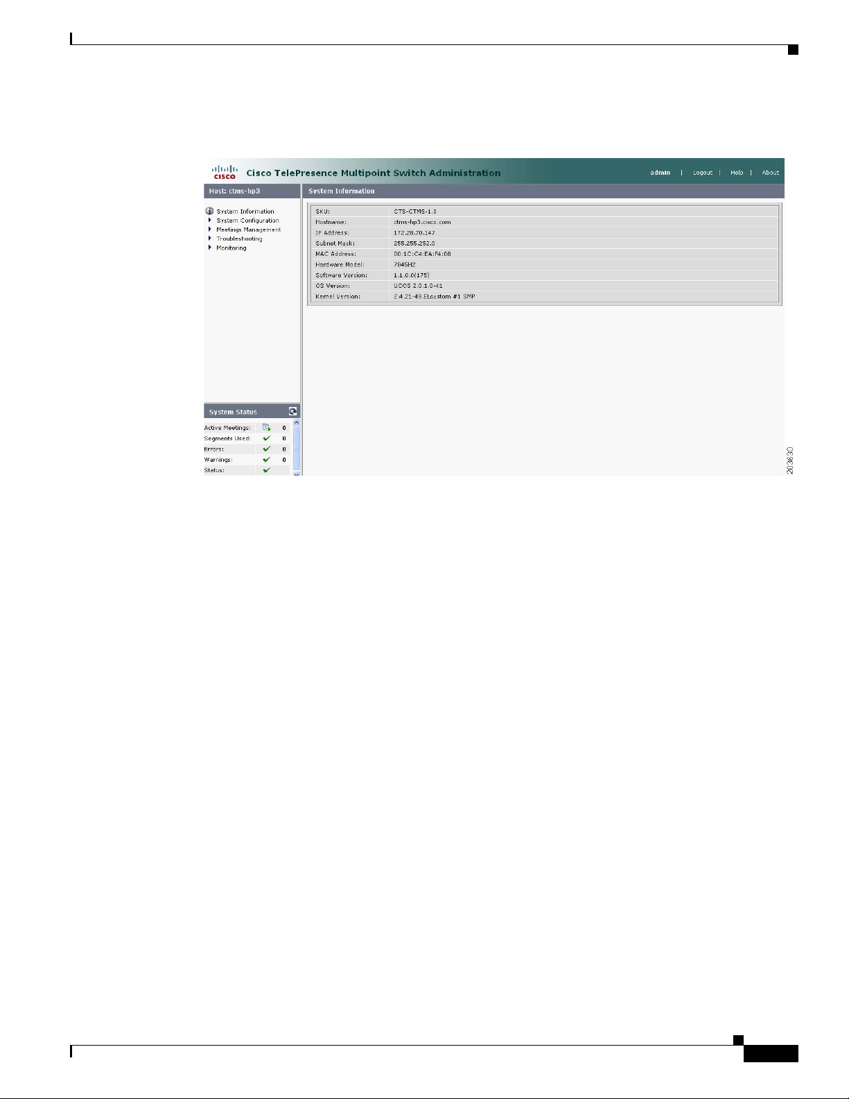
Figure 1-1 shows an example of the CTMS Administration software user interface.
1-10
Cisco TelePresence Multipoint Switch Release 1.1 Administration Guide
OL-12586-02
Page 13
Chapter 1 Using CTMS Administration Software
Figure 1-1 CTMS Administration Software User Interface
User Interface
Header
System Status
The header at the top of all CTMS Administration windows lists the name of the software application
and provides links for the following functions:
• Admin—Roll your cursor over “Admin” to display the name of the user current logged in to CTM
Administration.
• Logout—Click to log out of the system.
• Help—Click to display online help for using the CTMS Administration.
• About—Click to display software version and licensing information.
System status is always in view in the lower left corner of the CTMS Administration window. The system
status is updated every 60 seconds. Click the Refresh button in the upper right corner of the box to obtain
an immediate update.
The system status box shows the following information:
• Active meetings: Shows the number of meetings currently in progress.
• Errors: Shows the total number of system errors that are defined as either CRIT or ERROR. If the
total number of system errors is 0, a green check is displayed. If the total number of system errors
is more than 0, a red cross is displayed. System errors are described in “Chapter 7: Troubleshooting
the CTMS System.”
OL-12586-02
Cisco TelePresence Multipoint Switch Release 1.1 Administration Guide
1-11
Page 14

System Information
• Warnings: Shows the total number of system errors defined as WARN. If the total number of system
• Status: Shows the current state of all system processes. If all system processes are in the RUNNING
Navigation Pane
In the navigation pane at the left side of the CTMS Administration window, the System Configuration,
Meeting Management, Troubleshooting, and Monitoring folders display lists of tasks associated with
CTMS. Lists of tasks are also displayed in the content area of the window when you click any folder in
the navigation pane. Click the task name or the arrows in the left panel, or click the highlighted name in
the content area to navigate to tasks.
Content Area
Chapter 1 Using CTMS Administration Software
errors is 0, a green check is displayed. If the total number of system errors is more than 0, a red cross
is displayed. System warnings are described in “Chapter 7: Troubleshooting the CTMS System.”
state, a green check is displayed. If one or more processes are in the STOPPED state, a red check is
displayed. System processes are described in “Chapter 6: Monitoring CTMS System Processes.”
The right frame is the content area. When you select a folder or a task from the navigation pane, the
content associated with that item displays in the content area. The gray bar above the content area shows
the navigational path so you can quickly identify where you are at any time.
System Information
Choose System Information from the Navigation Pane to view information about the
Cisco TelePresence Multipoint Switch. The information displayed under System Information is
configured during CTMS software installation.
• SKU
• Hostname: Hostname of the CTMS.
• IP Address: IP address of the Cisco TelePresence Multipoint Switch.
• Hardware Model: Cisco MCS 7800 Series Media Convergence Server on which the Cisco
TelePresence Multipoint Switch is running.
• Software Version: Version of CTMS Administration software currently installed.
1-12
Cisco TelePresence Multipoint Switch Release 1.1 Administration Guide
OL-12586-02
Page 15

Contents
CHA PTER
2
Configuring Cisco Unified Communications
Manager for CTMS
Initial Release: May 5, 2008, OL-12586-02
Last Revised: August 4, 2008
• Overview, page 2-13
• Prerequisites, page 2-14
• Logging into the Unified CM Administration Application, page 2-14
• Creating a SIP Trunk Security Profile, page 2-14
• Creating a SIP Trunk, page 2-15
• Configuring a Route Pattern, page 2-16
Overview
• Configuring a Route Pattern, page 2-16
Before installing the CTMS Administration software on your Cisco MCS-7845 Media Convergence
Server, you need to perform the following configuration tasks in Cisco Unified Communications
Manager (Unified CM):
• Create a SIP security profile. This security profile will be used on the SIP trunk between CTMS and
Unified CM.
• Create a Session Initiation Protocol (SIP) trunk. The SIP trunk is used for communication between
Unified CM and CTMS.
• Create route patterns. A route pattern comprises a string of digits (an address) and a set of associated
digit manipulations that route calls to a route list or a gateway. Route patterns are used for routing
conferences numbers to the CTMS.
OL-12586-02
Cisco TelePresence Multipoint Switch Release 1.1 Administration Guide
2-13
Page 16

Chapter 2 Configuring Cisco Unified Communications Manager for CTMS
Prerequisites
Prerequisites
Before starting the tasks in this chapter, make sure that the following conditions are met or that you
understand the following information:
• Unified CM is running and using version 6.0 or later software.
• Cisco TelePresence System is running version 1.2.3 or later software. For interoperability with
legacy video conferencing devices, Cisco TelePresence System must be running version 1.3 or later
software.
For additional information about configuring Unified CM for Cisco TelePresence System, refer to the
Cisco Unified Communications Manager Installation Guide for the Cisco TelePresence System.
Logging into the Unified CM Administration Application
To log into the Unified CM Administration application:
Step 1 Open a web browser.
Step 2 Access a web browser that is supported by the Unified CM Administration application from any user PC
in your network. In the address bar of the web browser, enter the following URL:
https://
CUCM-server-name
where CUCM-server-name is the name or IP address of the server.
Note You may need to specify the address of the server where Unified CM is installed. If your network
uses DNS services, you can specify the hostname of the server. If your network does not use
DNS services, you must specify the IP address of the server.
Step 3 Log in with your assigned administrative privileges.
Step 4 Select Cisco Unified Communications Manager Administration in the Navigation field at the upper
right corner of the page and click Go to return to the Cisco Unified Communications Manager
Administration home page.
Creating a SIP Trunk Security Profile
To create a SIP trunk security profile:
Step 1 Click System. Under Security Profile, click SIP Trunk Security Profile.
Step 2 Click the Add New button at the bottom of the page or click the + sign at the top of the page.
2-14
Cisco TelePresence Multipoint Switch Release 1.1 Administration Guide
OL-12586-02
Page 17

Chapter 2 Configuring Cisco Unified Communications Manager for CTMS
Step 3 Enter the settings as indicated in Tab l e 2- 1 to configure the SIP trunk security profile. Leave default
settings for fields not included in Table 2-1.
.
Table 2-1 SIP Trunk Security Profile Settings
Field Required Setting
Name Yes Enter a text string identifying this SIP trunk
Description — Enter a text string describing this SIP trunk
Device Security Mode Yes Select Non Secure.
Incoming Transport Type Yes Select TCP+UDP.
Outgoing Transport Type Yes Select TCP.
Incoming Port Yes Enter 5060.
Step 4 Click the Save button at the bottom of the page.
Creating a SIP Trunk
security profile.
security profile.
Creating a SIP Trunk
To create a SIP trunk:
Step 1 Click Device. Click Trunk.
Step 2 Click the Add New button at the bottom or click the + sign at the top of the Trunk Configuration page.
Step 3 Select SIP Trunk from the Trunk Type pull-down menu, then click Next.
Step 4 Enter the settings as indicated in Tab l e 2- 2 to configure the SIP trunk. Leave default settings for fields
not included in Table 2- 2.
.
Table 2-2 SIP Trunk Settings
Field Required Setting
Device Information
Device Name Yes Enter a text string identifying this SIP trunk.
Description — Enter a text string describing this SIP trunk.
Device Pool Yes Select Default.
SIP Information
Destination Address Yes Enter the IP address of the CTMS.
SIP Trunk Security Profile Yes Select the SIP trunk security profile that you
SIP Profile Yes Select Standard SIP Profile.
created for CTMS.
OL-12586-02
Cisco TelePresence Multipoint Switch Release 1.1 Administration Guide
2-15
Page 18

Configuring a Route Pattern
Step 5 Click the Save button at the bottom of the page.
Configuring a Route Pattern
A route pattern allows a Unified CM-managed device to access another device by dialing its number.
Such devices may include gateways, Cisco TelePresence Multipoint Switch (CTMS) systems, or Cisco
Unified Video Conferencing (CUVC) MCUs. Each device requires its own unique route pattern.
To configure a route pattern:
Step 1 Click Call Routing. Under Route/Hunt, click Route Pattern.
Step 2 Click the Add New button at the bottom or click the + sign at the top of the Route Pattern Configuration
page.
Step 3 Enter the settings as indicated in Tab l e 2- 3 to configure the SIP trunk. Leave default settings for fields
not included in Table 2- 3.
.
Table 2-3 Route Pattern Configuration Settings
Chapter 2 Configuring Cisco Unified Communications Manager for CTMS
Field Required Setting
Pattern Definition
Route Pattern Yes Enter the route pattern, including numbers and
Description — Enter a text string describing this route pattern.
Gateway/Route List Yes Select the SIP trunk that you created for CTMS.
Call Classification Yes Select OnNet.
Step 4 Click the Save button at the bottom of the page.
wildcards (do not use spaces); for example, for
NANP, enter 9.@ for typical local access, or
8XXX for a typical private network numbering
plan. The uppercase characters A, B, C, and D are
valid characters.
Note See the “Wildcards and Special
Characters in Route Patterns and Hunt
Pilots” section in the Cisco CallManager
System Guide for more information about
wildcards.
2-16
Cisco TelePresence Multipoint Switch Release 1.1 Administration Guide
OL-12586-02
Page 19

Installing CTMS Administration Software
Initial Release: May 5, 2008, OL-12586-02
Last Revised: August 4, 2008
Contents
• Prerequisites, page 3-17
• Installing the CTMS Administration Software, page 3-18
Prerequisites
Before you install the Cisco TelePresence Multipoint Switch (CTMS) Administration software system
files, you need the following equipment and information:
CHA PTER
3
• Cisco TelePresence System (CTS)-1000 Release and/or CTS-3000 assembled and configured to
support TelePresence conferencing. For more information, refer to the following guides:
–
Cisco TelePresence System Release 1.3 Administrator's Guide
–
Cisco TelePresence 3000 Assembly, Use & Care, and Field Replacement Unit Guide
–
Cisco TelePresence 1000 Assembly, Use & Care, and Field Replacement Unit Guide
• Cisco MCS-7845-H2 or MCS-7845-I2 Media Convergence Server, installed and connected to a
Domain Name System (DNS) server and your network.
• Console able to access the Cisco MCS-7845-H2 Series Media Convergence Server.
• DVD that contains the CTMS Administration software application.
• Cisco Unified Communications Manager (Unified CM) 6.0 or higher configured to support CTS
Release 1.3 and integrated to work with CTMS, meaning that a SIP security profile, SIP trunk, and
route pattern specific to CTMS have been created. For more information about Unified CM for CTS
configuration, refer to Cisco Unified Communications Manager Installation Guide for the Cisco
TelePresence System.
OL-12586-02
Cisco TelePresence Multipoint Switch Release 1.1 Administration Guide
3-17
Page 20

Chapter 3 Installing CTMS Administration Software
Installing the CTMS Administration Software
Installing the CTMS Administration Software
To install the CTMS Administration software application:
Step 1 Insert the CTMS Administration software application DVD into the appropriate drive in the Cisco
MCS-7800 Series Media Convergence Server and boot up the host.
Step 2 Media Check: The system asks if you wish to perform a media check on the inserted DVD. Select Ye s
or No and press the Enter key. If you select No, the system bypasses the media check. If you select Yes ,
the system performs a checksum to make sure that the media on the DVD is intact. When the checksum
has successfully completed, select Okay and press the Enter key.
Note If the checksum fails, it could be because of a problem with either the DVD or the DVD drive.
The DVD or the DVD drive could need cleaning; the DVD data could be corrupted; or the
software image you are trying to load could be the wrong image.
Step 3 Hard Drive Check: The system then checks the status of the hard drives in the server. When cued to
update BIOS, press the Enter key to continue.
Step 4 Platform Installation Wizard: Select Proceed and press the Enter key to continue.
Step 5 Automatic Negotiation of Ethernet NIC Speed and Duplex: Select Yes and press the Enter key to
continue.
Step 6 DHCP: Cisco Systems recommends that you use a static IP address instead of DHCP. Select No to define
a specific static IP address and press the Enter key. Enter the following information:
• Hostname: Hostname of the CTMS server
• IP Address: IP address of the CTMS server
• IP Mask: Subnet mask for the CTMS server IP address
• Gateway Address: IP address for the gateway to the CTMS server
Select Okay and press the Enter key to continue.
Step 7 DNS Client: Select Yes and press the Enter key. Enter the following information:
• Primary DNS: IP address of the primary DNS server
• Secondary DNS: IP address of the secondary DNS server
• Domain: Domain name for your company
Select Okay and press the Enter key to continue.
Step 8 Platform Administrator Username and Password: Enter the following information:
• Administration ID
• Password
• Confirm Password
3-18
Select Okay and press the Enter key to continue.
Step 9 Certificate Information: Enter the following information:
• Organization
• Unit
• Location
Cisco TelePresence Multipoint Switch Release 1.1 Administration Guide
OL-12586-02
Page 21

Chapter 3 Installing CTMS Administration Software
• State
• Country
Select Okay and press the Enter key to continue.
Step 10 Network Time Protocol (NTP) Client Information: Enter the following information:
• NTP Server 1: IP address of the primary NTP server
• NTP Server 2: IP address of the secondary NTP server
• NTP Server 3 through 5: IP addresses of additional NTP servers
Select Okay and press the Enter key to continue.
Note The NTP servers identified must be the same for CTMS, CTS and CTM. It is recommended that
you provide at least three NTP servers.
Step 11 Platform Configuration Confirmation: Select Okay to continue with installation. select Back to go to
previous screens in the installation procedure, or Cancel to abort the installation. When you have made
your selection, press the Enter key. If you select Okay, platform and application installation takes
approximately 30 to 45 minutes. During installation, allow the default selection for the custom kernal to
proceed.
Step 12 After the CTMS Administration software application files have been installed, the system automatically
reboots. The system then performs a check of the network connectivity and setup. If the system
determines that any of the information you entered during the preceding steps is incorrect, a message is
displayed on the console, giving the you the following options:
Installing the CTMS Administration Software
• Retry: Select this option (and press the Enter key) to retry the installation procedure.
• Review: Select this option (and press the Enter key) if you need to change any of the data you entered
during the preceding installation steps. If you select this option, navigate to the appropriate
installation data entry screen, re-enter the data, and then proceed to the Platform Configuration
screen to re-initiate installation.
• Halt: Select this option (and press the Enter key) if you need to abort installation.
• Ignore: Select this option (and press the Enter key) to ignore the system warning.
Step 13 After the network connectivity and setup check, the system reboots again. Following this reboot, the
CTMS Administration software log-on screen is displayed. Enter your username and password to
continue with CTMS Administration software configuration.
OL-12586-02
Cisco TelePresence Multipoint Switch Release 1.1 Administration Guide
3-19
Page 22

Installing the CTMS Administration Software
Chapter 3 Installing CTMS Administration Software
3-20
Cisco TelePresence Multipoint Switch Release 1.1 Administration Guide
OL-12586-02
Page 23

Contents
CHA PTER
4
Configuring CTMS Administration Software
Revised: June 6, 2008, OL-12586-02
Last Revised: August 4, 2008
• Overview, page 4-21
• System Settings, page 4-22
–
Editing IP Settings, page 4-22
–
Editing Access Settings, page 4-23
–
Configuring and Editing QoS Settings, page 4-24
–
Configuring and Editing Resource Management, page 4-28
• Cisco Unified Communications Manager Settings, page 4-32
Overview
–
Configuring and Editing Unified CM Settings, page 4-33
–
Configuring and Editing SIP Profile Settings, page 4-33
• Configuring and Editing Cisco TelePresence Manager Settings, page 4-35
• Configuring and Editing Access Management, page 4-36
• Upgrading Software Version, page 4-40
• Interface Failover, page 4-41
The following sections describe the System Configuration parameters for the Cisco TelePresence
Multipoint Switch (CTMS). System Configuration is divided into the following areas:
• System Settings, page 4-22
• Cisco Unified Communications Manager Settings, page 4-32
• Configuring and Editing Cisco TelePresence Manager Settings, page 4-35
• Configuring and Editing Access Management, page 4-36
OL-12586-02
Cisco TelePresence Multipoint Switch Release 1.1 Administration Guide
4-21
Page 24
System Settings
System Settings
System Settings are initially configured during Cisco TelePresence Multipoint Switch (CTMS)
Administration software set up. Use the System Settings to make changes to these initial settings. System
Settings consists of four configuration areas:
• Editing IP Settings, page 4-22
• Editing Access Settings, page 4-23
• Configuring and Editing QoS Settings, page 4-24
• Configuring and Editing Resource Management, page 4-28
Editing IP Settings
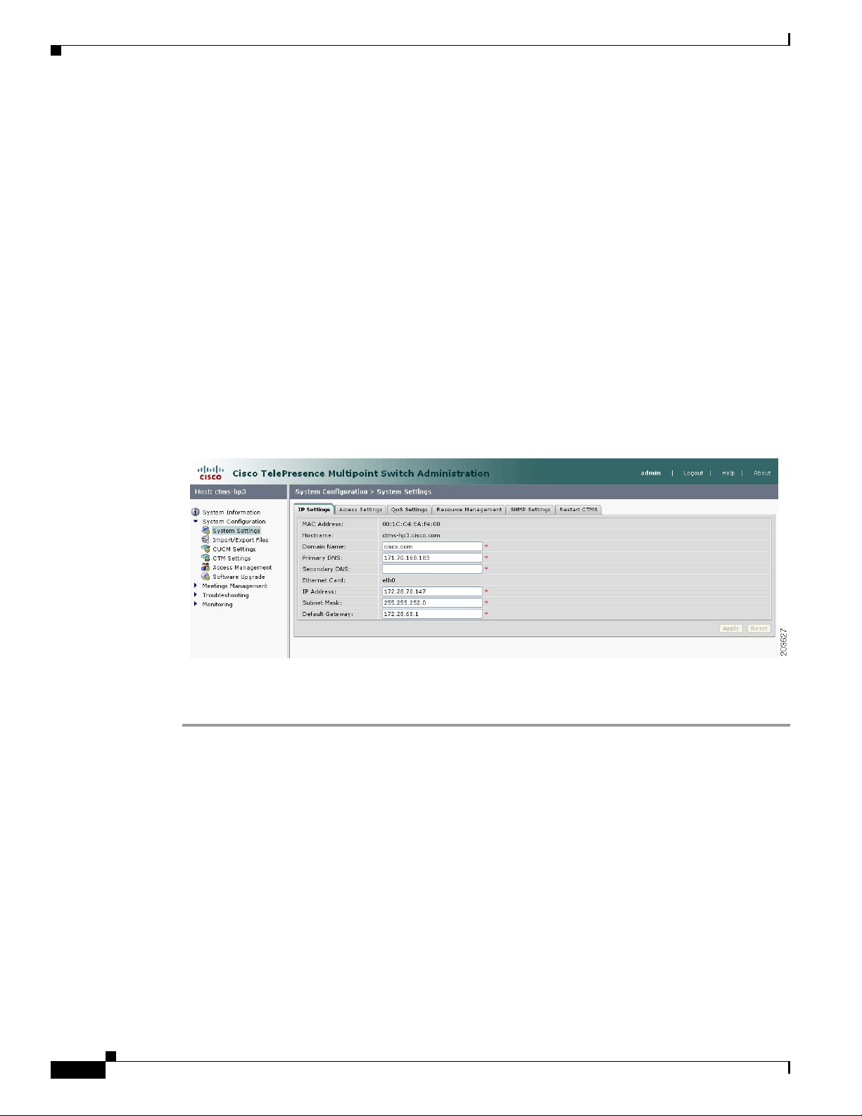
Figure 4-1 shows the IP Settings screen.
Figure 4-1 IP Settings
Chapter 4 Configuring CTMS Administration Software
4-22
To edit IP settings:
Step 1 Click System Settings under the System Configuration folder in the Navigation Pane.
Step 2 Click the IP Settings tab. IP Settings screen displays a table providing the IP Settings fields. Most of the
settings displayed on the IP Settings screen are configured during initial installation of the CTMS
Administration software. Only three fields can be configured on this screen:
• IP Address
• Subnet Mask
• Default Gateway
Edit settings (as needed) as described in Ta b l e 4- 1
Cisco TelePresence Multipoint Switch Release 1.1 Administration Guide
OL-12586-02
Page 25

Chapter 4 Configuring CTMS Administration Software
Table 4-1 IP Settings
Field or Button Setting
MAC Address (View only) MAC address of the MCU device on which the Cisco
Hostname (View only) Hostname configured for the MCU device on which the
Domain Name (View only) Domain name in which the MCU device on which the
Primary DNS (View only) IP address of the primary DNS for the MCU device on
Secondary DNS (View only) IP address of the secondary DNS for the MCU device on
Ethernet Card (View only) Ethernet card being used on the MCU server to connect
IP Address IP address of the Cisco TelePresence Multipoint Switch.
System Settings
TelePresence Multipoint Switch is located.
Cisco TelePresence Multipoint Switch is located.
Cisco TelePresence Multipoint Switch is located.
which the Cisco TelePresence Multipoint Switch is located.
which the Cisco TelePresence Multipoint Switch is located.
to the network.
Subnet Mask Subnet mask of the Cisco TelePresence Multipoint Switch.
Default Gateway Default gateway IP address for the Cisco TelePresence Multipoint
• To register new or modified settings, click Apply.
• To restore the original settings, click Reset.
Editing Access Settings
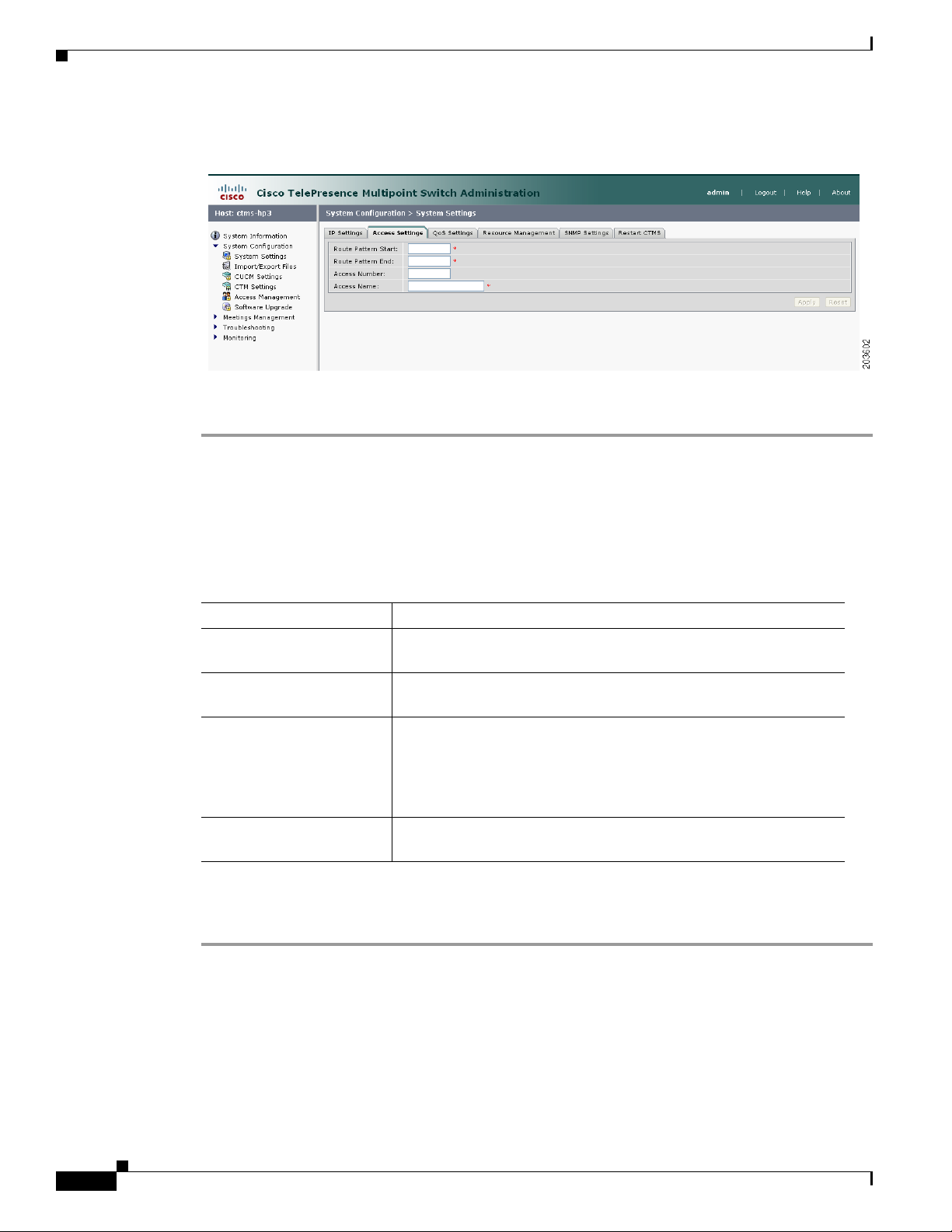
Figure 4-2 shows the Access Settings screen.
Note After changing the IP address, close your browser window,
then log into CTMS again using your new IP address.
Switch.
OL-12586-02
Cisco TelePresence Multipoint Switch Release 1.1 Administration Guide
4-23
Page 26
System Settings
Step 1 Click System Settings under the System Configuration folder in the Navigation Pane.
Step 2 Click the Access Settings tab. Access Settings displays a table providing the Access Settings
Chapter 4 Configuring CTMS Administration Software
Figure 4-2 Access Settings
To edit Access settings:
configuration fields. All of the settings on the Access Screen are derived from settings you configured
in Cisco Unified Communications Manager (Unified CM).
Edit settings (as needed) as described in Ta b l e 4- 2
Table 4-2 Access Settings
Field or Button Setting
Route Pattern Start Defines the first number in your defined route pattern as configured
in Unified CM.
Route Pattern End Defines the last number in your defined route pattern as configured
in Unified CM.
Access Number Displays the first number in the route pattern as defined in
Unified CM. CTMS Administration software (CTMSA)
automatically selects that number as the access number. That number
is used for scheduled meetings and cannot be used for static
meetings.
Access Name Descriptive name for the access number. Maximum number of
characters is 20.
• To register new or modified settings, click Apply.
• To restore the original settings, click Reset.
Configuring and Editing QoS Settings
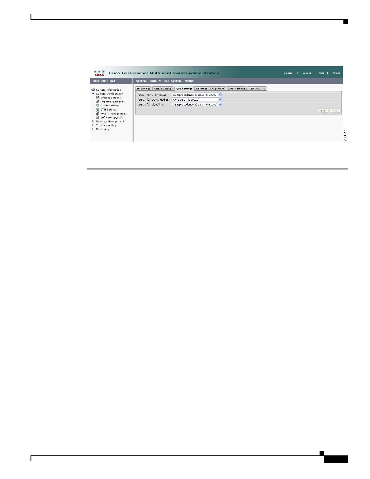
Figure 4-3 shows the QoS Settings screen.
Cisco TelePresence Multipoint Switch Release 1.1 Administration Guide
4-24
OL-12586-02
Page 27
Chapter 4 Configuring CTMS Administration Software
Figure 4-3 QoS Settings
To configure or edit QoS settings:
Step 1 Click System Settings under the System Configuration folder in the Navigation Pane to open the
System Settings window.
System Settings
Step 2 Click the QoS Settings tab. QoS Settings displays a table providing the QoS Settings configuration
fields.
Enter or edit settings (as needed) as described in Tab le 4- 3
OL-12586-02
Cisco TelePresence Multipoint Switch Release 1.1 Administration Guide
4-25
Page 28

System Settings
Chapter 4 Configuring CTMS Administration Software
Table 4-3 QoS Settings
Field or Button Setting
DSCP for Media Traffic marking values for voice and video traffic used for network
queuing. Available settings are:
• AF11 DSCP (001010)
• AF12 DSCP (001100)
• AF13 DSCP (001110)
• AF21 DSCP (010010)
• AF22 DSCP (010100)
• AF23 DSCP (010110)
• AF31 DSCP (011010)
• AF32 DSCP (011100)
• AF33 DSCP (011110)
• AF41 DSCP (100010)
• AF42 DSCP (100100)
• AF43 DSCP (100110)
• CS1 (precedence 1) DSCP (001000)
• CS2 (precedence 2) DSCP (010000)
• CS3 (precedence 3) DSCP (011000)
• CS4 (precedence 4) DSCP (100000)
• CS5 (precedence 5) DSCP (101000)
• CS6 (precedence 6) DSCP (110000)
• CS7 (precedence 7) DSCP (111000)
• Default DSCP (000000)
• EF DSCP (101110)
The default value for this field is CS4 (precedence 4) (100000). It is
recommended that you use the default value for this field.
4-26
Cisco TelePresence Multipoint Switch Release 1.1 Administration Guide
OL-12586-02
Page 29

Chapter 4 Configuring CTMS Administration Software
Table 4-3 QoS Settings
Field or Button Setting
DSCP for Signaling Traffic queuing techniques that define per-hop behavior based on the
System Settings
Differentiated Services Code Point (DSCP) value in the IP header of
a packet. control stream
Available settings are:
• AF11 DSCP (001010)
• AF12 DSCP (001100)
• AF13 DSCP (001110)
• AF21 DSCP (010010)
• AF22 DSCP (010100)
• AF23 DSCP (010110)
• AF31 DSCP (011010)
• AF32 DSCP (011100)
• AF33 DSCP (011110)
• AF41 DSCP (100010)
• AF42 DSCP (100100)
• AF43 DSCP (100110)
• CS1 (precedence 1) DSCP (001000)
• CS2 (precedence 2) DSCP (010000)
• CS3 (precedence 3) DSCP (011000)
• CS4 (precedence 4) DSCP (100000)
• CS5 (precedence 5) DSCP (101000)
• CS6 (precedence 6) DSCP (110000)
• CS7 (precedence 7) DSCP (111000)
• Default DSCP (000000)
• EF DSCP (101110)
The default value for this field is CS3 (precedence 3) (011000). It is
recommended that you use the default value for this field.
• To register new or modified settings, click Apply.
• To restore the original settings, click Reset.
OL-12586-02
Note We recommend that you use the same Quality settings for CTSM that you have configured in Cisco
Unified Communications Manager for Cisco TelePresence Systems endpoints.
Cisco TelePresence Multipoint Switch Release 1.1 Administration Guide
4-27
Page 30
System Settings
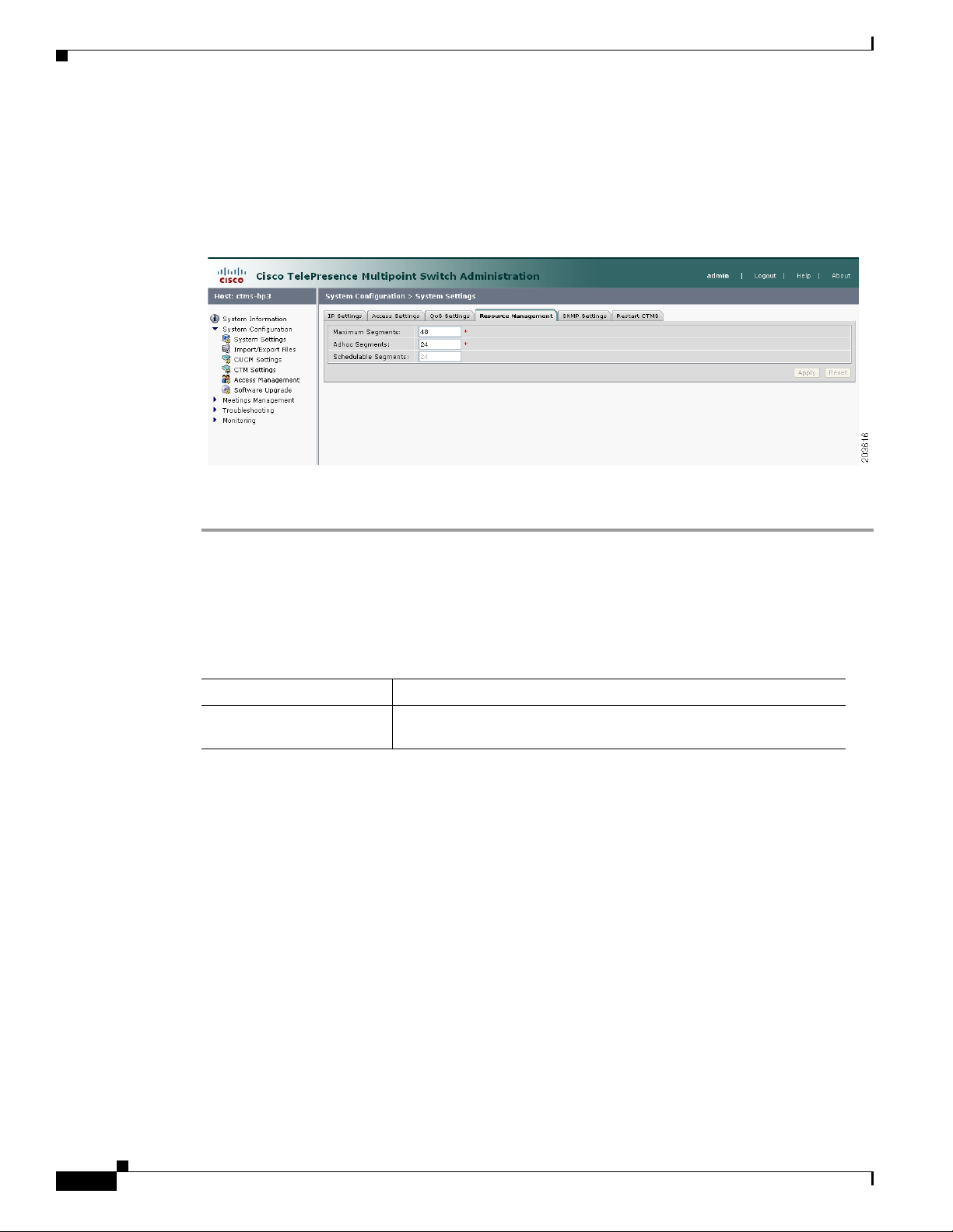
Configuring and Editing Resource Management
Figure 4-4 shows the Resource Management Settings screen.
Figure 4-4 Resource Management Settings
Chapter 4 Configuring CTMS Administration Software
To configure or edit Resource Management settings:
Step 1 Click System Settings under the System Configuration folder in the Navigation Pane.
Step 2 Click the Resource Management tab. Resource Management displays a table providing the Resource
Management Settings configuration fields.
Enter or edit settings (as needed) as described in Tab le 4- 4
Table 4-4 Resource Management Settings
Field or Button Setting
Maximum Segments Defines the total number of table segments (individual video
displays) this CTMS handles. Maximum number is 48.
4-28
Cisco TelePresence Multipoint Switch Release 1.1 Administration Guide
OL-12586-02
Page 31

Chapter 4 Configuring CTMS Administration Software
Table 4-4 Resource Management Settings (continued)
Field or Button Setting
Adhoc Segments Defines the maximum number of table segments available for
System Settings
impromptu meetings. By defining the number of table segments
available for adhoc meetings, you ensure that there will be sufficient
table segments available for scheduled meetings. Maximum number
is 48.
Note Combined total for Schedulable Table Segments and Ad hoc
Table Segments cannot exceed 48.
Note In Interop calls (meaning that the teleconference includes
both CTS and legacy teleconferencing (Cisco Unified Video
Conferencing (CUVC)), CUVC occupies one segment per
call. Segment use is dependint on the number of Interop
calls; for example, if there are three on-going Interop calls,
then three CTMS segments will be used to establish calls to
CUVC.
Schedulable Segments (View only) This field displays the number of table segments
available at any one time for scheduled meetings; CTMS
automatically derives this value by subtracting the defined number of
Ad Hoc Table Segments from the defined number of Maximum Table
Segments.
Note If you do not have Cisco TelePresence Manager installed, all table segments must be ad hoc.
• To register new or modified settings, click Apply.
• To restore the original settings, click Reset.
Configuring and Editing SNMP Settings
The Simple Network Management Protocol (SNMP) is an application layer protocol that facilitates the
exchange of management information between network devices; it enables network administrators to
manage network performance, find and solve network problems, and plan for network growth by
analyzing information gathered using MIBs.
With SNMP for CTMS, you first enable (or disable) SNMP; when you enable SNMP, you turn on the
SNMP daemon so CTMS is registered with SNMP (so that SNMP can begin monitoring CTMS and
gathering data). You can also designate a particular server where SNMP trap messages are gathered and
stored. Both of these configuration steps require separate username and password authentication.
By default, SNMP service is disabled. Once SNMP is enabled, the following default SNMP settings are
also enabled:
OL-12586-02
• One SNMP username set to “admin”. This name cannot be changed.
Cisco TelePresence Multipoint Switch Release 1.1 Administration Guide
4-29
Page 32

System Settings
Chapter 4 Configuring CTMS Administration Software
• SNMP service password set to “snmppassword”. The password should be changed.
• No trap receiver configured. Use the Trap Receiver Configuration fields in this window to configure
a trap receiver. The fields collect trap receiver username, password, authentication algorithm,
hostname or IP address, and port.
Figure 4-5 shows the SNMP Settings screen.
Figure 4-5 SNMP Settings
To edit SNMP settings:
Step 1 Click System Settings under the System Configuration folder in the Navigation Pane.
Step 2 Click the SNMP Settings tab. SNMP Settings displays a table providing the SNMP Settings
configuration fields.
Edit settings (as needed) as described in Ta b l e 4- 5
Table 4-5 SNMP Settings
Field or Button Setting
Engine ID (View only) The engine ID for the SNMP agent on this Cisco
TelePresence Multipoint Switch. This number is usually based on the
CTMS MAC address.
If you configure the trap receiver, this engine ID is used to create a
trap user on the trap receiver system and to compute the security
digest for authenticating and encrypting packets sent to a user on the
remote host.
SNMP Enable or disable SNMP for CTMS. Click the appropriate radio
button to select.
When SNMP is enabled, supply a password for the SNMP server in
the Configuration area.
Configuration
User Name SNMP server username.
4-30
Cisco TelePresence Multipoint Switch Release 1.1 Administration Guide
OL-12586-02
Page 33

Chapter 4 Configuring CTMS Administration Software
Table 4-5 SNMP Settings
Field or Button Setting
Current Password SNMP server password. The password must be 8 characters long.
Trap Receiver
Configuration
User Name Trap receiver username.
Current Password Trap receiver password. The password must be 8 characters long.
Authentication
Algorithm
• To register new or modified settings, click Apply.
• To restore the original settings, click Reset.
System Settings
Enter it twice for verification.
To select whether to use an SNMP trap receiver, click the Ye s or No
radio button, as appropriate.
When a trap receiver is used, supply login information for the trap
receiver in the following fields.
Enter it twice for verification.
Choose Message Digest 5 (MD5) or Secure Hash Algorithm (SHA)
for authentication.
Restarting CTMS
Figure 4-6 shows the Restart CTMS screen.
Figure 4-6 Restart CTMS Settings
To restart CTMS or to shutdown CTSM:
Step 1 Click System Settings under the System Configuration folder in the Navigation Pane.
OL-12586-02
Step 2 Click the Restart CTMS tab.
Step 3 Click Restart to restart—meaning shutdown and then reboot—CTMS.
Cisco TelePresence Multipoint Switch Release 1.1 Administration Guide
4-31
Page 34

Importing and Exporting Files
Step 4 Click Shutdown to completely shutdown CTMS.
Importing and Exporting Files
Import/Export Files enables you to reuse previously defined user and configuration files (such as
meeting templates) when upgrading to a new version of CTMS Administration Software. To reuse
previously defined user and configuration files, you must first export the files to a secure location,
upgrade to the new version of CTMS Administration software, and then import the files.
Figure 4-7 shows the Restart CTMS screen.
Figure 4-7 Import/Export Files Settings
Chapter 4 Configuring CTMS Administration Software
To import or export files:
Step 1 Click Import/Export Files under the System Configuration folder in the Navigation Pane.
Step 2 Click Export Files to import defined user and configuration files. Click Browse to select the exported
user and configuration files, then click Install Config Files to unzip and install the files.
Step 3 Click Import Files to import defined user and configuration files. Click Browse to select the exported
user and configuration files, then click Install Config Files to unzip and install the files.
Cisco Unified Communications Manager Settings
Cisco Unified Communications Manager Settings (Unified CM) consists of two configuration areas:
• Configuring and Editing Unified CM Settings, page 4-33
• Configuring and Editing SIP Profile Settings, page 4-33
4-32
Cisco TelePresence Multipoint Switch Release 1.1 Administration Guide
OL-12586-02
Page 35

Chapter 4 Configuring CTMS Administration Software
Configuring and Editing Unified CM Settings
Figure 4-8 shows the Unified CM Settings screen.
Figure 4-8 Unified CM Settings
Cisco Unified Communications Manager Settings
To configure or edit Unified CM settings:
Step 1 Click Unified CM Settings under the System Configuration folder in the Navigation Pane.
Step 2 Click the Unified CM Settings tab. Unified CM Settings displays a table providing the Unified CM
Settings configuration fields. Enter settings (as needed) as described in Table 4-6
Table 4-6 Unified CM Settings
Field or Button Setting
Unified CM 1 through 5 Hostnames or IP address(es) of the Cisco Unified Communications
Manager (Unified CM) server.
Note It is important to add all Unified CM servers in the cluster.
SIP Port Port number for Cisco Unified SIP IP Phones that are using UDP to listen
for SIP messages from Unified CM. The default setting equals 5060.
• To register new or modified settings, click Apply.
• To restore the original settings, click Reset.
Configuring and Editing SIP Profile Settings
Figure 4-9 shows the SIP Profile Settings screen.
Cisco TelePresence Multipoint Switch Release 1.1 Administration Guide
OL-12586-02
4-33
Page 36

Cisco Unified Communications Manager Settings
Figure 4-9 SIP Profile Settings
To configure or edit SIP Profile settings:
Step 1 Click Unified CM Settings under the System Configuration folder in the Navigation Pane to open the
Unified CM Settings window.
Step 2 Click the SIP Profile Settings tab. SIP Profile Settings displays a table providing the SIP Profile Settings
configuration fields.
Chapter 4 Configuring CTMS Administration Software
Enter or edit settings (as needed) as described in Tab le 4- 7
Table 4-7 SIP Profile Settings
Field or Button Setting
Retry Count for SIP Invite Specifies the number of times that Cisco Unified Communications
Manager (Unified CM) will re-send the INVITE message. This is a
required field. Minimum is 1. Maximum is 10 Default is 6.
Retry Count for SIP
non-Invite Request
Specifies the number of times that Unified CM will re-send the
non-INVITE message. This is a required field. Minimum is 1.
Maximum is 10 Default is 6.
SIP Expires Timer Specifies the maximum time that an INVITE message remains valid.
If Unified CM has not received an answer before this timer expires,
Unified CM tears down the call. This is a required field. Minimum is
60000 (msec). Maximum is 300000 (msec). Default is 180000
(msec).
SIP Timer T1 Specifies the lowest value, in milliseconds, of the retransmission
timer for SIP messages. Valid values include any positive number.
Default specifies 500.
SIP Timer T2 Specifies the highest value, in milliseconds, of the retransmission
timer for SIP messages. Valid values include any positive number.
Default specifies 4000.
Start Media Port Designates the start real-time protocol (RTP) port for media. Media
port ranges from 16384 to 32766. Default specifies 16384.
4-34
Cisco TelePresence Multipoint Switch Release 1.1 Administration Guide
OL-12586-02
Page 37
Chapter 4 Configuring CTMS Administration Software
Table 4-7 SIP Profile Settings
Field or Button Setting
Stop Media Port Designates the stop real-time protocol (RTP) port for media. Media
Transport Layer Protocol Select TCP or UDP for this field. Both transport types are supported.
• To register new or modified settings, click Apply.
• To restore the original settings, click Reset.
Configuring and Editing Cisco TelePresence Manager Settings
port ranges from 16384 to 32766. Default specifies 32766.
TCP is the recommended transport type.
Note Whenever the transport type is modified in CTMS, the
corresponding transport type for the Unified CM trunk
setting must be changed to match the CTMS transport type.
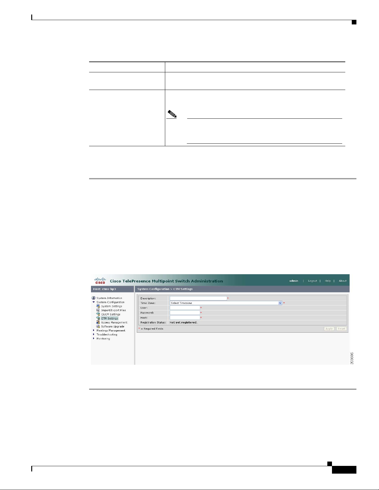
Configuring and Editing Cisco TelePresence Manager Settings
These setting are used to register CTMS with Cisco TelePresence Manager (CTS-Man) for scheduled
meetings.
Figure 4-10 shows the Cisco TelePresence Manager Settings screen.
Figure 4-10 Cisco TelePresence Manager Settings
To configure or edit CTS-Manager settings:
OL-12586-02
Step 1 Click CTM Settings under the System Configuration folder in the Navigation Pane to open the CTM
Settings window.
Step 2 CTM Settings displays a table providing the Cisco TelePresence Manager Settings configuration fields.
Enter or edit settings (as needed) as described in Tab le 4- 8
Cisco TelePresence Multipoint Switch Release 1.1 Administration Guide
4-35
Page 38

Configuring and Editing Access Management
Table 4-8 Cisco TelePresence Manager Settings
Field or Button Setting
Description Text describing or identifying this particular CTMS. The maximum
Time Zone Indicates the time zone in which the CTMS is located. Click “Time Zone”
User Username with which CTMS web services communicates with CTS
Chapter 4 Configuring CTMS Administration Software
number of characters for this field is 62 characters.
to display the list of available time zone options. Click option to highlight
and select.
Manager.
Note Usernames must be at least 5 characters, but not more than 64
characters in length, and can contain upper and lower case
alphanumeric characters and the underscore and dash characters.
The following usernames are not allowed: apache, daemon,
nobody, operator, and shutdown.
Note User name and password configured on the CTMS and CTS-Man
need to be the same.
Password Password with which CTMS web services communicates with CTS
Manager.
Note Passwords must be at least 5 characters, but not more than 64
characters in length, and can contain upper and lower case
alphanumeric characters and the underscore and dash characters.
The following usernames are not allowed: apache, daemon,
nobody, operator, and shutdown.
Note User name and password configured on the CTMS and CTS-Man
need to be the same.
Host Host is the IP address or host name of the CTS-Man.
Registration Status (View only) Registration state of the CTMS and CTS-Man.
• To register new or modified settings, click Apply.
• To restore the original settings, click Reset.
Configuring and Editing Access Management
CTMS administration software recognizes three different administrative roles; access to task folders is
dependent on defined administrative roles. So, administrative roles are considered a form of access
management and are defined using Access Management settings.
Figure 4-11 shows the Access Management screen.
Cisco TelePresence Multipoint Switch Release 1.1 Administration Guide
4-36
OL-12586-02
Page 39

Chapter 4 Configuring CTMS Administration Software
Figure 4-11 Access Management
To configure or edit Access Management settings:
Configuring and Editing Access Management
Step 1 Click Access Management under the System Configuration folder in the Navigation Pane to open the
Access Management window.
Step 2 Access Management initially displays a table providing the following information about already-defined
users as described in Tabl e 4-9.
Table 4-9 Access Management Table Field Descriptions
Field Description
Username Username of a specific CTMS user.
Administrator Administrators have the authority to perform all tasks associated
with CTMS, including configuring system settings, managing
multipoint meetings, maintaining, monitoring and troubleshooting
CTMS. Administrators have access to all folders in CTMS
Administration software. A green check in this field indicates that
the selected user has been designated as an administrator.
Meeting Scheduler Meeting Schedulers have the authority to perform multipoint
meeting management tasks, such as defining meeting templates, and
setting up (and breaking down, as necessary) ad hoc, static and
scheduled meetings. Meeting Schedulers have access to the Meeting
Management folder in CTMS Administration software. A green
check in this field indicates that the selected user has been
designated as a meeting scheduler.
Diagnostic Technician Diagnostic Technicians have the authority to perform CTMS
monitoring and troubleshooting tasks. Diagnostic Technicians have
access to the Troubleshooting and Monitoring folders in CTMS
Administration software. A green check in this field indicates that
the selected user has been designated as a diagnostic technician.
OL-12586-02
• To delete one of the defined administrators, click the radio button to the left of the table entry, and
then click Delete.
Cisco TelePresence Multipoint Switch Release 1.1 Administration Guide
4-37
Page 40

Configuring and Editing Access Management
• To edit one of the defined administrators, click the radio button to the left of the table entry, and then
click Edit.
• To define a new administrator, click New,
Step 3 When you click New from the Access Management screen, CTMS Administration software takes you to
the New User Settings table as shown in Figure 4-12.
Figure 4-12 New User Settings
Chapter 4 Configuring CTMS Administration Software
Step 4 Enter settings as described in Tab le 4-10
Table 4-10 New User Settings
Field or Button Setting
Username Username identifying a defined role as selected from the Role field.
Note Usernames must be at least 5 characters, but not more than
64 characters in length, and can contain upper and lower case
alphanumeric characters and the underscore and dash
characters. The following usernames are not allowed:
apache, daemon, nobody, operator, and shutdown.
Password Password for the username indicated in the Username field.
Note Passwords must be at least 5 characters, but not more than 64
characters in length, and can contain upper and lower case
alphanumeric characters and the underscore and dash
characters. The following usernames are not allowed:
apache, daemon, nobody, operator, and shutdown.
4-38
Cisco TelePresence Multipoint Switch Release 1.1 Administration Guide
OL-12586-02
Page 41

Chapter 4 Configuring CTMS Administration Software
Table 4-10 New User Settings
Field or Button Setting
Verify Password Re-enter the password defined for this user.
Role Defines a specific user role. In CTMS Administration software, there
Configuring and Editing Access Management
are three possible roles, each with specific levels of administrative
access:
• Administrator: Administrators have access to all screens and
configuration tasks in CTMS Administration software.
• Conference Scheduler: Conference-Schedulers have access only
to the Meeting Management screens and associated
configuration tasks in CTMS Administration software.
• Diagnostic Technician: Diagnostic Technicians have access only
to Monitoring and Troubleshooting screens and one task (system
restart) in CTMS Administration software.
Note A single user can have more than one role.
Click the appropriate radio button to select.
• To register new or modified settings, click Apply.
• To close this window without applying settings, click Close.
Step 5 To edit an existing user profile, click the radio button to the left of the table entry to select the user, and
then click Edit. When you click Edit from the Access Management screen, CTMS Administration
software takes you to the Edit User Settings table. Enter settings (as needed) as described in Table 4-11
Table 4-11 Edit User Settings
Field or Button Setting
User (View only.) Defined role.
Password Password for the username indicated in the Username field.
Note Passwords must be at least 5 characters, but not more than 64
characters in length, and can contain upper and lower case
alphanumeric characters and the underscore and dash
characters. The following usernames are not allowed:
apache, daemon, nobody, operator, and shutdown.
Verify New Password Re-enter the password defined for this user.
• To register new settings, click Save.
OL-12586-02
• To close this window without applying settings, click Close.
Cisco TelePresence Multipoint Switch Release 1.1 Administration Guide
4-39
Page 42

Upgrading Software Version
Upgrading Software Version
There are also two functions to assist you in maintaining the system software, as follows:
• Switch Version: The hard drive on the server on which CTMS is installed is partitioned into two
areas. Each area can contain a system image. Switch Version allows you to switch the location of
two stored versions of the system software.
• Upgrade Software: CTMS provides a patch file for upgrading system software. The Cisco-supplied
patch file can be stored on a CD-ROM or a Secure FTP (SFTP) host network. A wizard displays
dialog boxes to prompt you through the process.
Figure 4-13 shows the Software Upgrade screen.
Figure 4-13 System Upgrade Screen
Chapter 4 Configuring CTMS Administration Software
To switch software versions:
• Click the Switch Version button.
The system will swap the software versions and reboot. Screens will describe activity.
The active partition in the server hard drive contains the active system image. The software versions that
are loaded will be displayed in the Active Version and Inactive Version fields.
To upgrade software:
Step 1 To start the software upgrade process, click the Upgrade Software button.
The Source Selection dialog box appears.
If you need to stop the software installation, click the Cancel button when the button is active.
Step 2 Click the CD-ROM or Network radio button to choose the location of the patch file.
If you chose CD-ROM, click Next to go to the File Selection window.
If you chose Network, provide the hostname, login username, password, and the path to the patch file.
By default, port 22 is used to access the server; supply the correct port number, if required. Click Next
to go to the File Selection window.
Step 3 At the File Selection window, choose the file to load by clicking its radio button. Then click Next.
4-40
Cisco TelePresence Multipoint Switch Release 1.1 Administration Guide
OL-12586-02
Page 43

Chapter 4 Configuring CTMS Administration Software
Step 4 The Patch File Preparation window appears. Watch this window to monitor the progress of the file
download. Buttons will be inactive until the patch file is loaded.
Once the file is loaded, the window displays a Confirmation message.
The software wizard displays the software versions that are installed and provides active Yes and No
radio buttons so you can choose to switch the newly loaded software to the active partition.
Step 5 Click Yes or No to make your choice. Then click Next to finish the software upgrade task.
The install wizard displays a dialog window that logs the progress of the update.
Step 6 When the log indicates that the files have been switched, click Finish to complete this task.
Interface Failover
Interface failover provides a backup mechanism for Ethernet adapters. When enabled, the secondary
adapter handles all network traffic if the primary adapter or its connection fails.
Interface Failover
To enable interface failover:
Step 1 Make sure that the primary Ethernet adapter (Ethernet interface 0) is connected to the network and that
its static IP address and gateway parameters were correctly configured during system installation.
Step 2 Connect the secondary Ethernet cable (Ethernet interface 1) to a network switch. The connection port
can be on the same switch as Ethernet interface 0 or on a different switch but both Ethernet interface 0
and Ethernet interface 1 must be on the same gateway.
Step 3 From the Interface Failover window, click the Enable button, then click Apply.
Note If the Enable button is grayed out, check your network connection.
To disable interface failover:
Step 1 With no active meetings in progress, click the Disable button.
Step 2 Click Apply. Your network adapters will be configured and restarted and the interface failover disabled.
OL-12586-02
Cisco TelePresence Multipoint Switch Release 1.1 Administration Guide
4-41
Page 44

Interface Failover
Chapter 4 Configuring CTMS Administration Software
4-42
Cisco TelePresence Multipoint Switch Release 1.1 Administration Guide
OL-12586-02
Page 45

Contents
Managing Meetings
Initial Release: May 5, 2008, OL-12586-02
Last Revised: August 4, 2008
• Overview, page 5-43
• Defining and Editing Default Settings, page 5-43
• Creating and Editing Static Meetings, page 5-45
• Ad Hoc Meetings, page 5-49
–
Creating and Editing Ad Hoc Meetings, page 5-49
–
Creating and Editing Meeting Templates, page 5-51
• Viewing Scheduled Meetings, page 5-54
CHA PTER
5
• Viewing and Editing Active Meetings, page 5-55
Overview
This chapter describes how to set up and administer static (reservationless) and ad hoc meetings using
the CTMS Administration software.
Defining and Editing Default Settings
Default settings are those that the CTMS Administration software automatically assigns to meeting
profiles unless you configure specific settings for ad hoc and static meetings.
Figure 5-1 shows the Default Settings screen.
OL-12586-02
Cisco TelePresence Multipoint Switch Release 1.1 Administration Guide
5-43
Page 46

Defining and Editing Default Settings
Figure 5-1 Default Settings
To define default settings:
Step 1 Click Default Settings under the Meetings Management folder in the Navigation Pane.
Step 2 Default Settings displays a table providing the following configuration fields:
Chapter 5 Managing Meetings
Table 5-1 Default Settings
Field or Button Setting
Switching Policy Defines how CTMS calls are displayed during a meeting. CTMS displays
active speakers on screen. There are two active speaker display options:
• Segment: With segment switching, each individual table segment
(defined as a display and a camera) is displayed on the screen as that
segment becomes the active speaker.
• Site: When you select “site,” all table segments for a particular room
are displayed on screen when any segment in that room is the active
speaker.
Click the appropriate radio button to select.
Maximum Rooms Defines the maximum number of Cisco TelePresence rooms allowed to
dial into in a static multi-point meeting. The range is from 1 to 48.
Video announce If this option is selected, when a new attendee joins the meeting, the new
attendee is displayed for 2 seconds. Options are Yes and No. Click the
appropriate radio button to select.
5-44
Cisco TelePresence Multipoint Switch Release 1.1 Administration Guide
OL-12586-02
Page 47

Chapter 5 Managing Meetings
Table 5-1 Default Settings
Field or Button Setting
Quality This field sets the system bandwidth and screen resolution. A higher
Allow Downspeed When selected, if an endpoint joins the meeting with a lower Quality value
Creating and Editing Static Meetings
bandwidth increases video quality, but may also cause packets to be
dropped and video to be interrupted. Choices:
• Highest Detail, Best Motion: 4Mbps 1080p
• Highest Detail, Better Motion: 3.5Mbps, 1080p
• Highest Detail, Good Motion: 3Mbps, 1080p
• High Detail, Best Motion: 3Mbps, 720p
• High Detail, Better Motion: 2Mbps, 720p
• High Detail, Good Motion: 1Mbps, 720p
Default is Highest Detail, Best Motion: 4Mbps 1080p.
than other endpoints, the endpoint is allowed to join the meeting and all
other endpoints downgrade their Quality to match the lower value. If this
option is not selected, endpoints with a lower Quality value are not
allowed to join the meeting.
Options are Yes and No. Click the appropriate radio button to select.
Idle Meeting Termination
Enabled:
When selected, the meeting is terminated if the system does not detect an
active speaker for the value set in the Idle Meeting Termination Time field.
Options are Yes and No. Click the appropriate radio button to select.
Idle Meeting Termination
Time (minutes)
If the Idle Meeting Termination Enabled field is set to “Yes,” this field
defines the number of minutes before a meeting is terminated (if the
system does not detect an active speaker).
Possible values range from 1 to 59 minutes. The default is 10 minutes.
• To register new or modified settings, click Apply.
• To restore the original settings, click Reset.
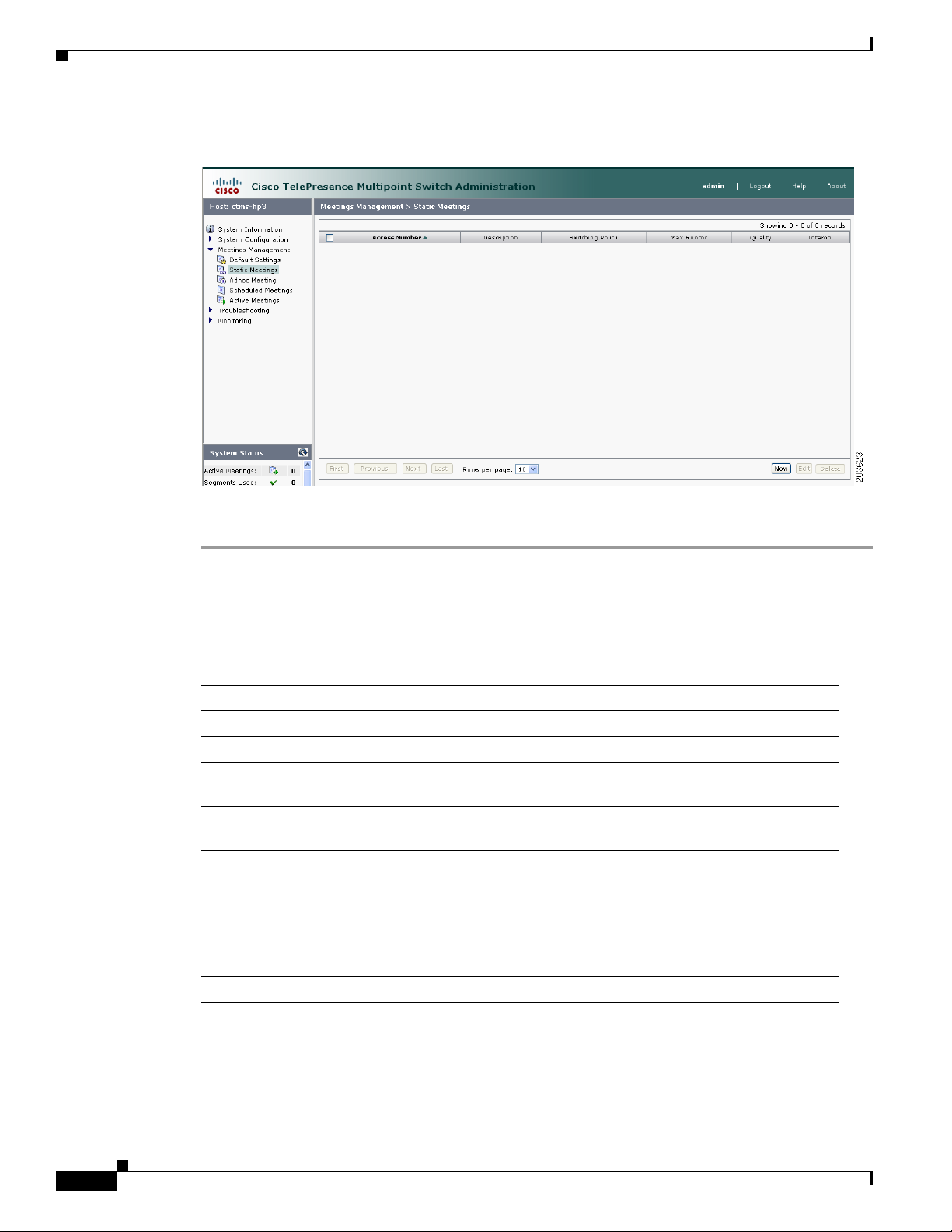
Creating and Editing Static Meetings
Static meetings are meetings that are permanently available after they have been configured. Each static
meeting has its own associated meeting number; meetings attendees dial into that specific number when
attending a static meeting. You can also add participants to a static meeting through the Active Meetings
page.
OL-12586-02
Note Static meetings use ad hoc meeting resources.
Figure 5-2 shows the Static Meetings screen.
Cisco TelePresence Multipoint Switch Release 1.1 Administration Guide
5-45
Page 48
Creating and Editing Static Meetings
Figure 5-2 Static Meetings
Chapter 5 Managing Meetings
To create or edit a static meeting:
Step 1 Click Static Meetings under the Meetings Management folder in the Navigation Pane.
Step 2 The Static Meetings setting screen initially displays a table providing the following information about
already defined static meetings:
Table 5-2 Static Meetings Table Field Descriptions
Field Description
Access Number Displays the access number that rooms call to attend this meeting.
Description Displays the defined description for this static meeting.
Switching Policy Displays the defined switching policy (site or segment) for this
static meeting.
Max Rooms Displays the maximum number of sites that can participate in this
static meeting.
Quality Sets the maximum bit rate and video resolution to be used for the
meeting.
Interop A green check indicates that this particular Cisco TelePresence
multipoint meeting supports Cisco Unified Video Conferencing
(CUVC) systems (interoperability mode). A red “X” indicates that
this meeting is not configured to cascade with CUVC systems.
CUVC Number (Optional) Number dialed to CUVC for interoperability meetings.
5-46
• To delete one of the defined static meetings, click the radio button to the left of the table entry, and
then click Delete.
• To edit one of the defined static meetings, click the radio button to the left of the table entry, and
then click Edit.
Cisco TelePresence Multipoint Switch Release 1.1 Administration Guide
OL-12586-02
Page 49

Chapter 5 Managing Meetings
• To define a new static meeting, click New.
Step 3 When you click Edit or New, CTMS Administration software takes you to the Static Meeting Settings
table. Figure 5-3 shows the New Static Meetings Settings screen.
Figure 5-3 New Static Meetings Settings
Creating and Editing Static Meetings
Step 4 Enter settings as described in Tab le 5-3:
Table 5-3 Static Meeting Settings
Field or Button Setting
Access Number Defines the telephone number that participants call to attend this
static meeting.
Meeting Description Text describing or identifying this static meeting. The maximum
number of characters for this field is 62 characters.
OL-12586-02
Cisco TelePresence Multipoint Switch Release 1.1 Administration Guide
5-47
Page 50

Creating and Editing Static Meetings
Table 5-3 Static Meeting Settings
Field or Button Setting
Switching Policy Defines how CTMS calls are displayed during a meeting. CTMS
Chapter 5 Managing Meetings
displays active speakers on screen. There are two active speaker
display options:
• Segment: (Speaker) With segment switching, each individual
table segment (defined as a display and a camera) is displayed
on the screen as that segment becomes the active speaker.
• Site: (Room) When you select “site,” all table segments for a
particular room are displayed on screen when any segment in
that room is the active speaker.
Click the appropriate radio button to select.
Note If you are running CTS 1.3 or later, you can control how
Cisco TelePresence calls are displayed from the Cisco
TelePresence phone interface. Press the Speaker softkey to
display the active segment; press the Room softkey to
display all segements from a particular site.
Maximum Rooms Defines the maximum number of Cisco TelePresence rooms allowed
to dial into in a static multi-point meeting. The range for this setting
is from 1 to 48.
Video Announce If this option is selected, when a new room joins the meeting, the new
room is displayed on-screen for 2 seconds. Options are Ye s and No.
Click the appropriate radio button to select.
Hosted Meeting Hosted meetings mean that one particular room is identified as the
host for a meeting; other meeting rooms will not be added to the
meeting until the host room dials in. If you have selected “Video
announce,” then each meeting room will be displayed in 2-second
intervals in the order that they joined the meeting.
Options are Yes and No. Click the appropriate radio button to select.
Host Room Number Defines the host Cisco TelePresence System room number.
Quality This field sets the system bandwidth and screen resolution. A higher
bandwidth increases video quality, but may also cause packets to be
dropped and video to be interrupted. Choices:
• Highest Detail, Best Motion: 4Mbps 1080p
• Highest Detail, Better Motion: 3.5Mbps, 1080p
• Highest Detail, Good Motion: 3Mbps, 1080p
• Highest Detail, Best Motion: 3Mbps, 720p
• Highest Detail, Better Motion: 2Mbps, 720p
5-48
• Highest Detail, Good Motion: 1Mbps, 720p
Default is Highest Detail, Best Motion: 4Mbps 1080p.
Cisco TelePresence Multipoint Switch Release 1.1 Administration Guide
OL-12586-02
Page 51

Chapter 5 Managing Meetings
Table 5-3 Static Meeting Settings
Field or Button Setting
Interop Determines whether this particular Cisco TelePresence multipoint
CUVC Number Defines the number that CTMS dials to establish contact with
Ad Hoc Meetings
meeting should automatically dial out to legacy Cisco Unified Video
Conferencing (CUVC) systems (interop).
Options are Ye s and No. Click the appropriate radio button to select.
CUVC. Each CUVC number must be unique for each CTMS
conference. The CUVC number consists of the service prefix and
then the remaining dialed digits. The service prefix can be the same
for different meetings. The remaining digits in the dialed number
designate the CUVC meeting instance.
Each CTMS conference requires its own CUVC meeting instance.
Note This number must start with the CUVC service prefix
defined during CUVC configuration.
• To register new or modified settings, click Apply.
• To restore the original settings, click Reset.
Ad Hoc Meetings
Ad Hoc meetings are impromptu meetings. Unlike static meetings (which, after they are defined, stay
active indefinitely), Ad Hoc meetings begin when they are configured, and end when the last meeting
room disconnects from the meeting, or when the administrator or conference-scheduler ends the
meeting. With Ad Hoc meetings, the CTMS dials meeting rooms invited to attend the meeting; after the
start of a meeting, the administrator can add rooms through the Active Meetings page.
If you have meetings that regularly include a particular set of meeting rooms, you can create meeting
templates; meeting templates are predefined groups of CTMS meeting room (end points).
Note Ad Hoc meeting do not support interoperability meetings in CTMS Release 1.1.
Ad Hoc Meeting configuration is divided into two separate tasks:
• Creating and Editing Ad Hoc Meetings, page 5-49
• Creating and Editing Meeting Templates, page 5-51
Creating and Editing Ad Hoc Meetings
Figure 5-4 shows the Ad Hoc Meetings screen.
Cisco TelePresence Multipoint Switch Release 1.1 Administration Guide
OL-12586-02
5-49
Page 52

Ad Hoc Meetings
Step 1 Click Ad Hoc Meetings under the Meetings Management folder in the Navigation Pane to open the Ad
Step 2 CTMS Administration software displays the New Ad Hoc Meeting Settings table. Enter settings as
Chapter 5 Managing Meetings
Figure 5-4 Ad Hoc Meetings
To create or edit an ad hoc meeting:
Hoc Meeting window.
described in Ta ble 5- 4:
Table 5-4 New Ad Hoc Meetings Settings
Field Description
Meeting Template This field allows you to select a predefined meeting template.
(Meeting templates are predefined groups of CTMS end points.)
Click the down arrow to display the available meeting templates;
double click a particular template to select.
Rooms Defines the meeting room number of the CTMS end points invited
to attend this ad hoc meeting. When entering multiple meeting room
numbers, separate each room number with a carriage return by
pressing Enter.
Meeting Description Text describing or identifying this particular meeting. The
maximum number of characters for this field is 62 characters.
5-50
Cisco TelePresence Multipoint Switch Release 1.1 Administration Guide
OL-12586-02
Page 53

Chapter 5 Managing Meetings
Table 5-4 New Ad Hoc Meetings Settings
Field Description
Switching Policy Defines how CTMS calls are displayed during a meeting. CTMS
Ad Hoc Meetings
displays active speakers on screen. There are two active speaker
display options:
• Segment: (Speaker) With segment switching, each individual
table segment (defined as a display and a camera) is displayed
on the screen as that segment becomes the active speaker.
• Site: (Room) When you select “site,” all table segments for a
particular room are displayed on screen when any segment in
that room is the active speaker.
Click the appropriate radio button to select.
Note If you are running CTS 1.3 or later, you can control how
Cisco TelePresence calls are displayed from the Cisco
TelePresence phone interface. Press the Speaker softkey to
display the active segment; press the Room softkey to
display all segements from a particular site.
Video Announce When selected, if a new attendee joins the meeting, the attendee is
displayed on-screen for 2 seconds. Options are Yes and No. Click
the appropriate radio button to select.
Quality (per Display) This field sets the system bandwidth and screen resolution. A higher
bandwidth increases video quality, but may also cause packets to be
dropped and video to be interrupted. Choices:
• Highest Detail, Best Motion: 4Mbps 1080p
• Highest Detail, Better Motion: 3.5Mbps, 1080p
• Highest Detail, Good Motion: 3Mbps, 1080p
• High Detail, Best Motion: 3Mbps, 720p
• High Detail, Better Motion: 2Mbps, 720p
• High Detail, Good Motion: 1Mbps, 720p
Default is Highest Detail, Best Motion: 4Mbps 1080p.
• To register new or modified settings, click Apply.
• To restore the original settings, click Reset.
Creating and Editing Meeting Templates
OL-12586-02
The Meeting Template setting screen initially displays a table providing the following information about
already defined meeting templates. Figure 5-5 shows the Meeting Templates screen.
Cisco TelePresence Multipoint Switch Release 1.1 Administration Guide
5-51
Page 54

Ad Hoc Meetings
Chapter 5 Managing Meetings
Figure 5-5 Meeting Templates
To create or edit a meeting template:
Step 1 Click Ad Hoc Meetings under the Meetings Management folder in the Navigation Pane to open the Ad
Hoc Meetings window.
Step 2 Click the Meeting Template tab to display the Meeting Template page.
Step 3 The Meeting Template setting screen initially displays a table providing the following information about
already defined meeting templates, as described in Ta bl e 5- 5.
Table 5-5 Meeting Template Table Field Descriptions
Field Description
ID Name identifying this particular meeting template.
Description Text describing this particular meeting template.
• To display a defined number of table rows, click the down arrow next to Rows per page. Click to
highlight and select predetermined amounts.
• To delete one of the defined meeting templates, click the radio button to the left of the table entry,
and then click Delete.
• To edit one of the defined meeting templates, click the radio button to the left of the table entry, and
then click Edit.
• To define a new meeting template, click New.
5-52
Step 4 When you click Edit or New, CTMS Administration software displays the Meeting Templates Settings
table. Enter settings as described in Tab l e 5- 6 :
Cisco TelePresence Multipoint Switch Release 1.1 Administration Guide
OL-12586-02
Page 55

Chapter 5 Managing Meetings
Table 5-6 Meeting Templates Settings
Field Description
Description Name identifying this particular meeting template. This name
Rooms Defines the meeting room number of the CTMS end points invited
Meeting Description Text describing this particular meeting template. The maximum
Switching Policy Defines how CTMS calls are displayed during a meeting. CTMS
Ad Hoc Meetings
appears in the drop-down list of defined meeting templates. The
maximum number of characters for this field is 62 characters
to attend this ad hoc meeting. When entering multiple meeting room
numbers, separate each room number with a carriage return by
pressing “enter.”
number of characters for this field is 62 characters
displays active speakers on screen. There are two active speaker
display options:
• Segment: (Speaker) With segment switching, each individual
table segment (defined as a display and a camera) is displayed
on the screen as that segment becomes the active speaker.
• Site: (Room) When you select “site,” all table segments for a
particular room are displayed on screen when any segment in
that room is the active speaker.
Click the appropriate radio button to select.
Note If you are running CTS 1.3 or later, you can control how
Cisco TelePresence calls are displayed from the Cisco
TelePresence phone interface. Press the Speaker softkey to
display the active segment; press the Room softkey to
display all segements from a particular site.
Quality This field sets the system bandwidth and screen resolution. A higher
bandwidth increases video quality, but may also cause packets to be
dropped and video to be interrupted. Choices:
• Highest Detail, Best Motion: 4Mbps 1080p
• Highest Detail, Better Motion: 3.5Mbps, 1080p
• Highest Detail, Good Motion: 3Mbps, 1080p
• High Detail, Best Motion: 3Mbps, 720p
• High Detail, Better Motion: 2Mbps, 720p
• High Detail, Good Motion: 1Mbps, 720p
Default is Highest Detail, Best Motion: 4Mbps 1080p.
• To register new or modified settings, click Apply.
OL-12586-02
• To restore the original settings, click Reset.
Cisco TelePresence Multipoint Switch Release 1.1 Administration Guide
5-53
Page 56

Viewing Scheduled Meetings
Viewing Scheduled Meetings
Scheduled Meetings lists all of the meetings scheduled using CTS-Man.
Figure 5-6 shows the Scheduled Meetings screen.
Figure 5-6 Scheduled Meetings
Chapter 5 Managing Meetings
To view information about scheduled meetings:
Step 1 Click Scheduled Meetings under the Meetings Management folder in the Navigation Pane to open the
Scheduled Meetings window.
Step 2 The Scheduled Meetings setting screen initially displays a table providing the following information
about already scheduled meetings, as described in Table 5-7
Table 5-7 Scheduled Meetings Table Field Descriptions
Field Description
ID Meeting IDs for the scheduled meetings. Click the arrow to change
the order (descending, ascending based on Meeting IDs) in which
the scheduled meetings are displayed.
Description Displays the defined meeting description.
Start Time GMT-8 Displays the start time (Greenwich Mean Time, Pacific Standard
Time) for this scheduled meeting. Click the arrow to change the
order (descending, ascending based on meeting start time) in which
the scheduled meetings are displayed.
End Time GMT-8 Displays the end time (Greenwich Mean Time, Pacific Standard
Time) for this scheduled meeting. Click the arrow to change the
order (descending, ascending based on meeting end time) in which
the scheduled meetings are displayed.
5-54
Cisco TelePresence Multipoint Switch Release 1.1 Administration Guide
OL-12586-02
Page 57

Chapter 5 Managing Meetings
• Click the radio button to the left of a table entry to select a specific scheduled meeting.
• Click Details to display additional information about the selected scheduled meeting.
• Click Refresh to refresh the Schedule Meetings table displayed.
• To display a defined number of table rows, click the down arrow next to Rows Per Pag e. Click to
highlight and select predetermined amounts.
• If there are multiple pages listing log files, click the First, Previous, Next, or Last button to navigate
to the desired page.
Viewing and Editing Active Meetings
Active Meetings is where you either view information about an active meeting, or edit meetings that are
currently in progress. Figure 5-7 shows the Active Meetings screen.
Figure 5-7 Active Meetings Screen
Viewing and Editing Active Meetings
OL-12586-02
To view or edit an active meeting:
Step 1 Click Active Meetings under the Meetings Management folder in the Navigation Pane to open the
Active Meetings window.
Step 2 The Active Meetings setting screen displays a table listing all currently active meetings. Meetings are
listed in the table by Meeting ID number.
• To display a defined number of table rows, click the down arrow next to Rows Per Pag e. Click to
highlight and select predetermined amounts.
• If there are multiple pages, click the First, Previous, Next, or Last button to navigate to the desired
page.
Cisco TelePresence Multipoint Switch Release 1.1 Administration Guide
5-55
Page 58

Viewing and Editing Active Meetings
• Click Refresh to refresh the Active Meetings table displayed.
Step 3 To use the filter at the top of the table to find a particular meeting, enter either the Meeting ID number
or the Meeting Room number in the appropriate field and then click Filter.
Step 4 Click the radio button to the left of a table entry to select a particular meeting. Click Edit to display the
Active Meetings setting table. Active Meeting management tasks (and information about active
meetings) are described in Table 5-8
Table 5-8 Active Meetings Settings
Field Description
Meeting ID Displays the Meeting ID Number of the meeting selected. To delete
Meeting Description Displays the defined description for this meeting.
Meeting Type Displays the defined meeting type. Meeting types are static and
Room1, Room2... Lists the CTS end points (meeting rooms) attending this meeting. To
Chapter 5 Managing Meetings
this meeting (in other words, end this meeting), click the
Delete Meeting radio button. Click Apply to end the meeting.
ad hoc.
delete a particular CTS end point, click the Delete Room radio
button for that particular room. Click Apply to remove that room
from the meeting.
Note For interoperability meetings, the CUVC connection is
shown as one room in the Maximum Rooms setting.
Add Room(s) Defines additional meeting room numbers (CTMS end points) to
attend this meeting. When entering multiple meeting room
numbers, separate each room number with a carriage return by
pressing “Enter.”
Note An interoperability connection cannot be dynamically
added to a conference. It must be configured in the Static
Meeting definition.
5-56
Cisco TelePresence Multipoint Switch Release 1.1 Administration Guide
OL-12586-02
Page 59

Chapter 5 Managing Meetings
Table 5-8 Active Meetings Settings
Field Description
Switching Policy Defines how CTMS calls are displayed during a meeting. CTMS
Viewing and Editing Active Meetings
displays active speakers on screen. There are two active speaker
display options:
• Segment: (Speaker) With segment switching, each individual
table segment (defined as a display and a camera) is displayed
on the screen as that segment becomes the active speaker.
• Site: (Room) When you select “site,” all table segments for a
particular room are displayed on screen when any segment in
that room is the active speaker.
Click the appropriate radio button to select.
Note If you are running CTS 1.3 or later, you can control how
Cisco TelePresence calls are displayed from the Cisco
TelePresence phone interface. Press the Speaker softkey to
display the active segment; press the Room softkey to
display all segements from a particular site.
Video Announce When selected, if a new attendee joins the meeting, the attendee is
displayed on-screen for 2 seconds. Options are Yes and No. Click
the appropriate radio button to select.
Quality This field sets the system bandwidth and screen resolution. A higher
bandwidth increases video quality, but may also cause packets to be
dropped and video to be interrupted. Choices:
• Highest Detail, Best Motion: 4Mbps 1080p
• Highest Detail, Better Motion: 3.5Mbps, 1080p
• Highest Detail, Good Motion: 3Mbps, 1080p
• High Detail, Best Motion: 3Mbps, 720p
• High Detail, Better Motion: 2Mbps, 720p
• High Detail, Good Motion: 1Mbps, 720p
Default is Highest Detail, Best Motion: 4Mbps 1080p.
VIP Mode When selected, one endpoint is defined as the “VIP.” A VIP is
broadcast to all other meeting attendees for the entire meeting. The
VIP’s endpoint continues to switch between endpoints with active
speakers. Only one VIP can be defined per meeting.
Options are “Yes” and “No.” Click the appropriate radio button to
select.
Lock Locking the meeting means that no settings can be changed for this
meeting. Options are Yes and No. Click the appropriate radio button
to select.
OL-12586-02
Cisco TelePresence Multipoint Switch Release 1.1 Administration Guide
5-57
Page 60

Viewing and Editing Active Meetings
Table 5-8 Active Meetings Settings
Field Description
VIP Source Defines how the VIP is displayed to all endpoints. Options are:
<Meeting Attendees> Defines roles for participates if VIP mode is selected. Options are:
Chapter 5 Managing Meetings
Room: If selected, all segments for the CTS endpoint identified as
“VIP” are displayed.
Center Segment: If selected (and the CTS endpoint identified as
“VIP” is a CTS-3000), then only the center segment is displayed.
Click the appropriate radio button to select.
VIP: This attendee is broadcast to all other meeting attendees for
the entire meeting. The VIP’s endpoint continues to switch between
endpoints with active speakers. Only one VIP can be defined per
meeting.
Viewer: The VIP is broadcast to this attendee.
NA: The attendee is neither a viewer or a VIP. The NA’s endpoint
continues to switch between end points with active speakers.
Click the appropriate radio button to select.
• To register new or modified settings, click Save.
• To exit and return to the Active Meetings list, click Close.
5-58
Cisco TelePresence Multipoint Switch Release 1.1 Administration Guide
OL-12586-02
Page 61

Contents
CHA PTER
Troubleshooting the CTMS System
Initial Release: May 5, 2008, OL-12586-02
Last Revised: August 4, 2008
• Overview, page 6-59
• Viewing CTMS Alarms and System Error Messages, page 6-60
• Configuring the Severity Level of System Error Messages, page 6-62
• Filtering the Log File Table Listings, page 6-63
• Downloading Log Files, page 6-64
• Troubleshooting Specific Issues, page 6-64
6
Overview
The Troubleshooting folder contains tools that enable you to do the following:
• View the latest CTMS alarms and system error messages
• Configure the severity level of system level error messages and alarms for specific process areas
• Filter the Log File table listings.
Figure 6-1 shows the main Troubleshooting window,
OL-12586-02
Cisco TelePresence Multipoint Switch Release 1.1 Administration Guide
6-59
Page 62

Chapter 6 Troubleshooting the CTMS System
Viewing CTMS Alarms and System Error Messages
Figure 6-1 Troubleshooting Window
Viewing CTMS Alarms and System Error Messages
You can view CTMS alarms, systems error and system warning messages in one of two ways:
• Click System Errors under the Troubleshooting folder in the Navigation Pane. You will see a list
of all warning and error messages.
• From the System Status bar, click the icon for Warnings or Errors.
–
If you click the icon for Warnings , you will see endpoint alert information. Warnings are issued
every 20 seconds when an endpoint crosses its packet loss threshold. If congestion continues for
more than 40 seconds, the endpoint will be dropped.
–
If you click the icon for Errors, you will see endpoint drop information. Whenever an endpoint
drops from high packet loss, an error is issued with the error code “CONGESTION.”
Whether you select System Errors under Troubleshooting, or click Error or Warning icons, messages are
displayed in the following tabular format as shown in Figure 6-2.
6-60
Cisco TelePresence Multipoint Switch Release 1.1 Administration Guide
OL-12586-02
Page 63
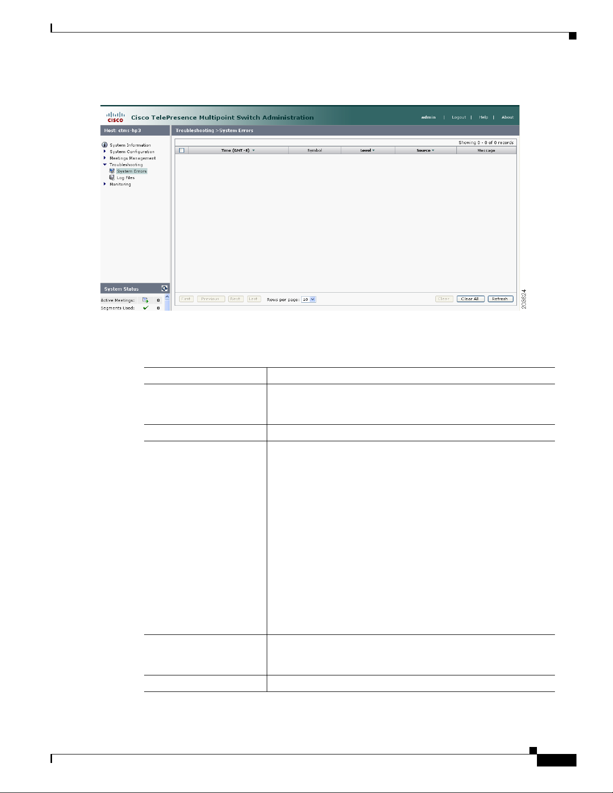
Chapter 6 Troubleshooting the CTMS System
Figure 6-2 System Errors Screen
Viewing CTMS Alarms and System Error Messages
Table 6-1 System Error Table Field Descriptions
Field Description
Time (GMT-8) Displays the time at which this error occurred. Click the arrow to
change the order (descending, ascending based on time) in which
the errors are displayed.
Symbol Text string (name) of the error message or alarm.
Level Indicates the severity level of the error message or alarm. There are
eight severity levels as follows:
• OFF
• CRIT
• ERROR
• WA R N
• INFO
• DEBUG
• DEBUG2
• DEBUG3
Click the arrow to change the order (descending, ascending based
on level) in which the errors are displayed.
Source Indicates the CTMS system process associated with this alarm or
error message. Click the arrow to change the order (descending,
ascending based on source) in which the errors are displayed.
Message Message describing the error or alarm.
OL-12586-02
Cisco TelePresence Multipoint Switch Release 1.1 Administration Guide
6-61
Page 64

Chapter 6 Troubleshooting the CTMS System
Configuring the Severity Level of System Error Messages
• To display a defined number of table rows, click the down arrow next to Rows Per Page. Click to
highlight and select predetermined amounts.
• If there are multiple pages listing log files, click the First, <Previous, Next>, or Last button to
navigate to the desired page.
• To delete one of the error messages, click the radio button to the left of the table entry, and then click
Clear.
• To delete all error messages displayed, click Clear All.
Configuring the Severity Level of System Error Messages
To configure the severity level of system level error messages and alarms for specific process areas:
Step 1 Click Log Files under the Troubleshooting folder in the Navigation Pane to open the Log Files window.
Figure 6-3 shows the Log File Screen.
Figure 6-3 Log Files Screen
Step 2 At the top of the Log Files screen, there is a table listing the following CTMS system processes:
• CCS
6-62
• Conference Manager
• Execution Manager
• Media Processor
• Switching
To the left of each process is a drop-down list, listing the following severity levels:
• OFF
Cisco TelePresence Multipoint Switch Release 1.1 Administration Guide
OL-12586-02
Page 65

Chapter 6 Troubleshooting the CTMS System
• CRIT
• ERROR
• WA R N
• INFO
• DEBUG
• DEBUG2
• DEBUG3
Click the down arrow to display the drop-down list of defined levels of severity, and then click to
highlight and select a specific severity level for all error messages and alarms associated a particular
CTMS system process.
Note Log levels create varying amounts of data; for example, DEBUG creates more log entries than CRIT.
Because verbose logs can impact system performance, use verbose logs only to track a problem.
Filtering the Log File Table Listings
Filtering the Log File Table Listings
To filter the log files displayed in the Log File Table:
Step 1 Click Log Files under the Troubleshooting folder in the Navigation Pane to open the Log Files window.
Step 2 At the middle of the Log Files screen, click the down arrow to the right of Processes to display a list of
CTMS process areas, then click to highlight and select a specific process area on which to filter log files.
Choices are:
• All
• CCS
• Conference Manager
• Execution Manager
• Media Processor
• Switching
• SIP
• Web- UI
• CDR Logs
• Core
• Alarm Logs
OL-12586-02
Step 3 Click the Filter button to display the logs files associated with the selected process area in the Log Files
table.
Cisco TelePresence Multipoint Switch Release 1.1 Administration Guide
6-63
Page 66

Downloading Log Files
Downloading Log Files
To download log files from the Log File table:
Step 1 Click Log Files under the Troubleshooting folder in the Navigation Pane to open the Log Files window.
Step 2 At the bottom of the Log Files screen is the Log File table, which lists the available log files. The table
is organized as follows:
Table 6-2 Log Table Field Descriptions
Field Description
Filename Filename of the log file. Click the arrow to change
Process CTMS system process area. Click the arrow to
Last Modified (GMT-8) Time (Greenwich Mean Time, Pacific Standard
Size Size (in kilobytes) of the compressed log file.
Chapter 6 Troubleshooting the CTMS System
the order (descending, ascending based on
alphabetical order of the filenames) in which the
log files are displayed.
change the order (descending, ascending based on
alphabetical order of the processes) in which the
log files are displayed.
Time) at which the log file was collected. Click
the arrow to change the order (descending,
ascending based on time) in which the log files are
displayed.
Step 3 To display a defined number of table rows, click the down arrow next to Rows per Page. Click to
highlight and select predetermined amounts. If there are multiple pages listing log files, click the First,
Previous, Next, or Last button to navigate to the desired page.
Step 4 Click the filename of a log file to download that file. Click the Download All button to download all log
files listed.
Troubleshooting Specific Issues
Table 6-3 describes some specific problems and possible solutions.
6-64
Cisco TelePresence Multipoint Switch Release 1.1 Administration Guide
OL-12586-02
Page 67

Chapter 6 Troubleshooting the CTMS System
Table 6-3 Specific Problems and Possible Solutions
Problem Possible Solutions
Unable to connect to static meetings or
to initiate ad hoc meetings
Unable to connect to static meetings
but able to connect to ad hoc meetings
Unable to connect to ad hoc meetings
but able to connect to static meetings
Scheduled meetings don’t connect
Cisco TelePresence Interoperability:
Unified CM sends an error message of
“Service not available” to CTMS when
CTMS tries to establish call to CUVC.
Troubleshooting Specific Issues
1. Verify network connectivity.
2. Verify IP address of the CTMS configured on
Unified CM SIP trunk.
1. Verify the that static number being dialed is a valid
number.
2. Verify that SIP Trunk security profile “Outbound
transport type” is set to “UDP.”
3. Verify that all Unified CM servers are entered in
Unified CM settings.
1. Verify that the CTS endpoints numbers are entered
correctly.
2. Verify that rooms are available.
1. Check the registration status of the CTMS on the CTM
page.
2. Verify that the scheduled meeting is listed on the CTMS
(under Scheduled Meetings).
1. Check to see if there are sufficient ports. Unified CM
delivers a “Service not available” message when CTMS
places a call to CUVC and there are an insufficient
number of ports available.
2. Verify the number dialed for the CUVC connection is
defined to Unified CM as a SIP trunk, and is correctly
configured.
OL-12586-02
Cisco TelePresence Multipoint Switch Release 1.1 Administration Guide
6-65
Page 68

Troubleshooting Specific Issues
Chapter 6 Troubleshooting the CTMS System
6-66
Cisco TelePresence Multipoint Switch Release 1.1 Administration Guide
OL-12586-02
Page 69

Contents
CHA PTER
Monitoring CTMS System Processes
Initial Release: May 5, 2008, OL-12586-02
Last Revised: August 4, 2008
• Overview, page 7-67
• Monitoring System Status, page 7-68
• Monitoring and Restarting System Processes, page 7-69
• Viewing Call Statistics, page 7-70
• Room Testing, page 7-72
7
Overview
The Monitor folder contains tools that enable you to monitor the overall CTMS system state and the
running state of individual processes. Figure 7-1 shows the initial Monitoring window.
Figure 7-1 Monitoring Window
OL-12586-02
Cisco TelePresence Multipoint Switch Release 1.1 Administration Guide
7-67
Page 70

Monitoring System Status
Monitoring System Status
To view the status of CTMS system processes:
Step 1 Click System Status under the Monitoring folder in the Navigation Pane to open the System Status
window. Figure 7-2 shows the System Status screen.
Figure 7-2 System Status
Chapter 7 Monitoring CTMS System Processes
7-68
Step 2 System Status shows snapshots of the following CTMS system processes:
• Active CPU Load Percentage
• Active CPU Load Average Value
• Traffic Analysis for <interface>
• Packet Discards for <interface>
• Free Memory
• Free Swap + Real Memory
• Root Disk / Usage %
• Open TCP Connections
Click each snapshot to reveal daily, weekly, monthly and yearly averages.
Cisco TelePresence Multipoint Switch Release 1.1 Administration Guide
OL-12586-02
Page 71

Chapter 7 Monitoring CTMS System Processes
Monitoring and Restarting System Processes
Monitoring and Restarting System Processes
Process Status lists all processes currently running; the information on this page automatically refreshes
every 10 seconds.
To monitor or restart system processes:
Step 1 Click Process Status under the Monitoring folder in the Navigation Pane to open the Process Status
window. Figure 7-3 shows the Process Status screen.
Figure 7-3 Process Status Screen
Step 2 The Process Status screen initially displays a table providing the following information:
Table 7-1 Process Status Table Field Descriptions
Field Description
Process Process name
Status Status of this particular process.
Step 3 To display a defined number of table rows, click the down arrow next to “Rows per page.” Click to
highlight and select predetermined amounts. If there are multiple pages listing log files, click the First,
Previous, Next, or Last button to navigate to the desired page.
Step 4 Click “Restart” to restart all of the processes.
Warning
When you restart CTMS system processes, all active meetings are dropped. Check for active meetings
before using this command.
OL-12586-02
Cisco TelePresence Multipoint Switch Release 1.1 Administration Guide
7-69
Page 72

Viewing Call Statistics
Viewing Call Statistics
Use Call Statistics to view detailed RTP information about all call segments for active CTMS meetings.
To view call statistics:
Step 1 Click Call Status under the Monitoring folder in the Navigation Pane to open the Call Statistics
window. Figure 7-4 shows the Call Statistics screen.
Figure 7-4 Call Statistics Screen
Chapter 7 Monitoring CTMS System Processes
7-70
Step 2 The initial Call Statistics screen displays a table providing the following information, listing all currently
active meetings by ID numbers:
Table 7-2 Call Statistics Table Field Descriptions
Field Description
Meeting ID ID number uniquely identifying an active meeting.
Description Text describing the active meeting.
Type Displays the defined meeting type. Meeting types are static and
ad hoc.
Rooms Lists the CTS end points (meeting rooms) attending this meeting.
Duration Length of time this meeting has been active, listed in hours, minutes
and seconds.
Segments Total number of segments for all rooms attending this meeting.
Step 3 To use the filter at the top of the table to find a particular meeting, enter either the Meeting ID number
or the Room number in the appropriate field and then press “Filter.”
Cisco TelePresence Multipoint Switch Release 1.1 Administration Guide
OL-12586-02
Page 73

Chapter 7 Monitoring CTMS System Processes
Step 4 To display a defined number of table rows, click the down arrow next to “Rows per page.” Click to
highlight and select predetermined amounts. If there are multiple pages, click the First, Previous, Next,
or Last button to navigate to the desired page.
Step 5 Click Refresh to refresh the active meetings displayed.
Step 6 Click the radio button to the left of a table entry to select a particular meeting. Click View Details to
display an abbreviated view of RTP statistics for the selected meeting. To see all RTP call statistics
details for a particular meeting, click Details from the abbreviated view.
Step 7 Click View All Endpoint Details to display a subset of audio and video RTP statistics for all active
meetings. To see all RTP call statistics details for all meeting, click Details from the abbreviated view.
Complete RTP statistic details include the following information for each CTMS call segment:
Audio Statistics
• SSRC (Receive)
• SSRC (Transmit)
• Max Jitter (Period)
• Max Jitter (Call)
Viewing Call Statistics
• Mean Jitter (Period)
• Mean Jitter (Call)
• Jitter Standard Deviation (Period)
• Jitter Standard Deviation (Call)
• Jitter Spike (Period)
• Jitter Spike (Call)
• Jitter Spike Rate % (Period)
• Jitter Spike Rate % (Call)
• Total Packets (Receive)
• Total Packets (Transmit)
• Lost Packet Rate % (Receive)
• Lost Packet Rate (Transmit)
• Duplicate Packets
• Out of Order Packets
• Total Switching (Call)
• Max Switching (Period)
Video Statistics
• SSRC (Receive)
OL-12586-02
• SSRC (Transmit)
• Max Jitter (Period)
• Max Jitter (Call)
• Mean Jitter (Period)
• Mean Jitter (Call)
Cisco TelePresence Multipoint Switch Release 1.1 Administration Guide
7-71
Page 74

Room Testing
Chapter 7 Monitoring CTMS System Processes
• Jitter Standard Deviation (Period)
• Jitter Standard Deviation (Call)
• Jitter Spike (Period)
• Jitter Spike (Call)
• Jitter Spike Rate % (Period)
• Jitter Spike Rate % (Call)
• Total Packets (Receive)
• Total Packets (Transmit)
• Lost Packet Rate % (Receive)
• Lost Packet Rate (Transmit)
• Duplicate Packets
• Out of Order Packets
• Total Switching (Call)
• Max Switching (Period)
• Feedback Packets Dropped
• Total NAKs
• Max Frame Window (Period)
• Max Frame Window (Call)
• Frame Window Spikes (Period)
• Frame Window Spikes (Call)
• Frame Window Spike Rate % (Period)
• Frame Window Spike Rate % (Call)
• IDR Packets (Received)
• IDR Packets (Transmit)
Room Testing
Use Room Testing to perform loopback or force switch testing.
To perform loopback or force switch testing:
Step 1 Click Room Testing under the Monitoring folder in the Navigation Pane to open the Room Testing
window. Figure 7-5 shows the Room Testing screen.
7-72
Cisco TelePresence Multipoint Switch Release 1.1 Administration Guide
OL-12586-02
Page 75

Chapter 7 Monitoring CTMS System Processes
Figure 7-5 Room Testing Screen
Room Testing
Step 2 The initial Room Testing screen displays a table providing the following information, listing all currently
active meetings by ID numbers:
Table 7-3 Room Testing Table Field Descriptions
Field Description
Meeting ID ID number uniquely identifying an active meeting.
Description Text describing the active meeting.
Type Displays the defined meeting type. Meeting types are static and
ad hoc.
Rooms Lists the CTS end points (meeting rooms) attending this meeting.
Duration Length of time this meeting has been active, listed in hours, minutes
and seconds.
Segments Total number of segments for all rooms attending this meeting.
Step 3 To use the filter at the top of the table to find a particular meeting, enter either the Meeting ID number
or the Room number in the appropriate field and then press “Filter.”
Step 4 To display a defined number of table rows, click the down arrow next to “Rows per page.” Click to
highlight and select predetermined amounts. If there are multiple pages, click the First, Previous, Next,
or Last button to navigate to the desired page.
Step 5 Click “Refresh” to refresh the active meetings displayed.
Step 6 Click the radio button to the left of a table entry to select a particular meeting. Click “Details” to display
the Room Testing screen for the rooms in that meeting.
OL-12586-02
a. Click “Loopback” to display the transmitted camera image (image is looped-back so that attendees
see themselves) in each of the rooms for the selected meeting.
Cisco TelePresence Multipoint Switch Release 1.1 Administration Guide
7-73
Page 76

Room Testing
Chapter 7 Monitoring CTMS System Processes
b. Click “Force Switch” to force site switching between all of the rooms in the selected meeting.
c. Click “Close” to return to the Room Testing active meeting listing screen.
7-74
Cisco TelePresence Multipoint Switch Release 1.1 Administration Guide
OL-12586-02
Page 77

Contents
CHA PTER
8
Interoperability with Legacy Video Conferencing
Devices
Initial Release: May 5, 2008, OL-12586-02
Last Revised: August 4, 2008
• Overview, page 8-75
–
How Cisco TelePresence Interoperability Works, page 8-75
–
Benefits, page 8-77
–
Caveats, page 8-77
• Prerequisites, page 8-78
• Configuring Cisco TelePresence Interoperability, page 8-79
–
Configuring Unified CM for Cisco TelePresence Interoperability, page 8-79
–
Configuring CUVC for Cisco TelePresence Interoperability, page 8-81
–
Configuring CTMS for Cisco TelePresence Interoperability, page 8-85
Overview
Cisco TelePresence is based on open standards, including SIP, H.264 and G.711. With Cisco
TelePresence System (CTS) Release 1.3 and CTMS Release 1.1, Cisco TelePresence now supports
interoperability between Cisco TelePresence systems and standard definition video conferencing/video
telephony using the Cisco Unified Video Conferencing 3500 series MCU (CUVC).
How Cisco TelePresence Interoperability Works
As shown in Figure 8-1, CTS endpoints send a copy of their audio in G.711 format to the CTMS server.
CTMS then determines which CTS segment is emitting the most dominant audio and requests that
segment to send a copy of that segment’s video in Common Intermediate Format (CIF) resolution. CTMS
OL-12586-02
Cisco TelePresence Multipoint Switch Release 1.1 Administration Guide
8-75
Page 78
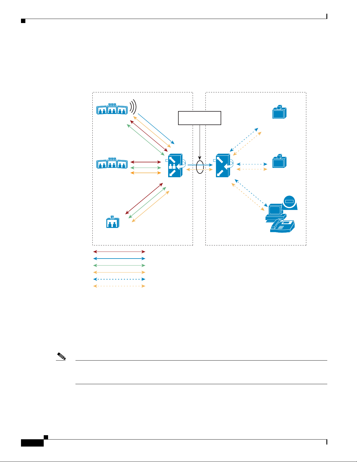
Overview
Chapter 8 Interoperability with Legacy Video Conferencing Devices
mixes the G.711 channels for all CTS endpoints into a single G.711 audio and switches CIF and G.711
to CUVC. As the dominant audio segment changes throughout the meeting, CTMS switches the CIF
video stream accordingly. Audio-only participants on the CUVC side can join directly into the CUVC.
Figure 8-1 Cisco TelePresence Interoperability: From CTS/CTMS to CUVC
London
Active Segment
To ky o
CTMS
Cascade
CUVC
H.323 or H.320
Videoconferencing
SIP
Videoconferencing
New York
IP
Video Telephony
203652
H.264 1080p
H.264 CIF
AAC-LD
G.711
Any video format CUVC supports
Any audio format CUVC supports
As shown in Figure 8-2, audio and video coming from CUVC to CTMS is switched to all CTS endpoints
when the audio coming from CUVC is deemed to be the most dominant segment. The CIF image from
CUVC is presented on the left screen of each CTS-3000 surrounded by black borders. With the
CTS-1000, the CIF image is displayed when CTMS senses that the CUVC participant is the active
speaker. The incoming 352x288 CIF image is stretched to 4CIF when displayed on either the CTS-1000
or CTS3000 high-definition plasma screen.
Note If you wish to see more than one CUVC participant displayed at one time, you can customize the CUVC
MCU layout configuration to display up to 16 CUVC participants. We recommend the 1x1 layout for
consistency with the Telepresence experience.
8-76
Cisco TelePresence Multipoint Switch Release 1.1 Administration Guide
OL-12586-02
Page 79
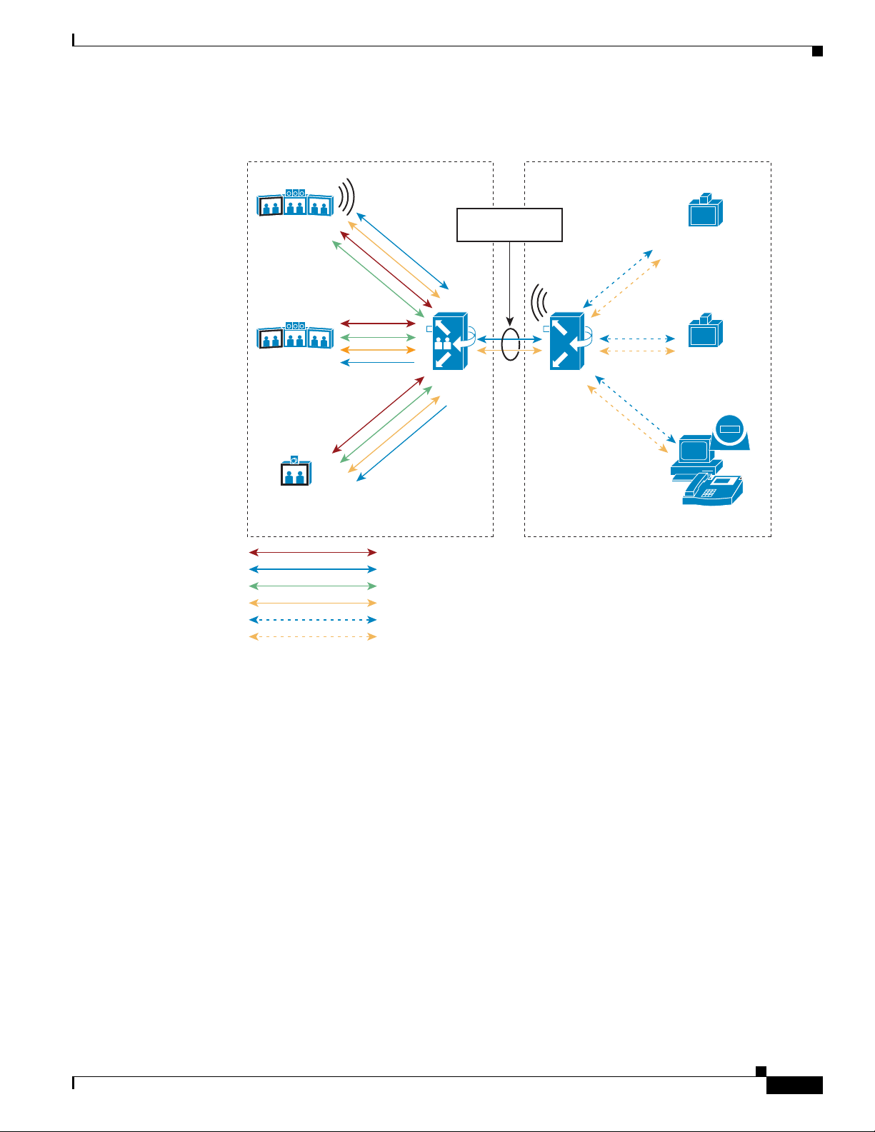
Chapter 8 Interoperability with Legacy Video Conferencing Devices
Figure 8-2 Cisco TelePresence Interoperability: From CUVC to CTS/CTMS
London
To ky o
New York
Active Segment
CTMS
Cascade
CUVC
Overview
H.323 or H.320
Videoconferencing
SIP
Videoconferencing
Benefits
Caveats
IP
Video Telephony
203653
H.264 1080p
H.264 CIF
AAC-LD
G.711
Any video format CUVC supports
Any audio format CUVC supports
Cisco TelePresence Interoperability maintains the immersive experience for Cisco TelePresence meeting
participants. It also provides standards-based interoperability with minimal additional hardware (CUVC
3500 Series MCU) requirements. CTS and CTMS software upgrades are available at no charge.
• Cisco TelePresence Interoperability increases the required amount of bandwidth to and from each
CTS by an additional 704 kbps to transmit and receive the CIF and 64 kbps to transmit and receive
G.711 streams.
• The interoperability segment is limited to CIF resolution video at 768 kbps and G.711 audio in
CTMS Release 1.1.
OL-12586-02
• CUVC is the only supported MCU in this release. CUVC requires software version 5.5.0.0.54 or
later.
Cisco TelePresence Multipoint Switch Release 1.1 Administration Guide
8-77
Page 80

Prerequisites
• CUVC participants will not experience the spatial audio generated by CTS. CUVC participants hear
• CUVC as an SCCP conference resource managed by Unified CM is not a supported option.The
• CTS participants hear CUVC participants mixed together in G.711; audio will be heard from the
• CTS and CUVC participants are not able to share slides or documents using H.239. Use another
• Far End Camera Control (FECC) is not available to CTS participants during an interoperability call.
• Each interop conference uses one CTMS port and one CUVC port for each conference because each
• Encryption is not supported for CTMS, Release 1.1, including interoperability calls.
Prerequisites
Chapter 8 Interoperability with Legacy Video Conferencing Devices
all Cisco TelePresence participants mixed together in G.711.
CUVC must be defined as a SIP trunk (and optionally an H.323 gateway) to Unified CM.
same segment as that which is showing the CIF video.
application for document sharing between CTS and CUVC, such as MeetingPlace or WebEx.
meeting utilizes a port for the cascade link. For example, CTMS normally can support 48 segments,
and CUVC-3515-24 can support up to 24 participants. During interop meetings, CTMS supports a
maximum of 47 segments and CUVC supports a maximum of 23 participants.
Interoperability between traditional video conferencing devices and CTS requires three components:
• CTMS
• Cisco Unified Communications Manager (Unified CM)
• CUVC MCU
The software and hardware requirements for Cisco TelePresence Interoperability are as follows:
CUVC Software and Hardware Requirements
• CUVC MCU Release 5.5.0.0.54:MP or later
• CUVC EMP Release 5.5.2.0.2:EMP or later
For additional information about configuring CUVC, refer to the Configuration Guide for the Cisco
Unified Videoconferencing 3545 MCU Release 5.5.
Unified CM Software Requirements
• Unified CM Software Release 6.0 or later
For additional information about configuring Unified CM for Cisco TelePresence System, refer to the
Cisco Unified Communications Manager Installation Guide for the Cisco TelePresence System.
For information about configuring Unified CM, refer to Cisco Unified Communications Manager
Ve rs i on 6 . 0 and Cisco Unified Communications Manager Version 6.1.
CTS Endpoint Software Requirements
• CTS Software Release 1.3 or later
8-78
For more information about CTS Administration Software, refer to the Cisco TelePresence System
Release 1.3 Administrator’s Guide.
Cisco TelePresence Multipoint Switch Release 1.1 Administration Guide
OL-12586-02
Page 81

Chapter 8 Interoperability with Legacy Video Conferencing Devices
Configuring Cisco TelePresence Interoperability
Configuring Cisco TelePresence Interoperability
To configure Cisco TelePresence Interoperability, you must complete the following configuration tasks:
• Configure Unified CM to support Cisco TelePresence Interoperability
• Configure CUVC to support Cisco TelePresence Interoperability
• Add at least one static meeting to CTMS with interoperability enabled
Configuring Unified CM for Cisco TelePresence Interoperability
To configure Unified CM for Cisco TelePresence Interoperability, you must create a SIP trunk security
profile and a SIP trunk using the same configuration parameters as you would in defining a SIP trunk for
CTMS. Then you must add a new route pattern in Unified CM that points to the CUVC. CTMS dials the
CUVC using the number defined in the “CUVC number” field of the CTMS meeting definition when the
first CTS participant joins the meeting.
Creating a SIP Trunk Security Profile
To create a SIP trunk security profile:
Step 1 Click System. Under Security Profile, click SIP Trunk Security Profile.
Step 2 Click the Add New button at the bottom of the page or click the + sign at the top of the page.
Step 3 Enter the settings as indicated in Tab l e 8- 1 to configure the SIP trunk security profile. Leave default
settings for fields not included in Table 8-1.
.
Table 8-1 SIP Trunk Security Profile Settings
Field Required Setting
Name Yes Enter a text string identifying this SIP trunk
security profile.
Description — Enter a text string describing this SIP trunk
security profile.
Device Security Mode Yes Select Non Secure.
Incoming Transport Type Yes Select TCP+UDP.
Outgoing Transport Type Yes Select TCP.
Incoming Port Yes Enter 5060.
Step 4 Click the Save button at the bottom of the page.
OL-12586-02
Note Use the same SIP Trunk Security Profile settings for the CTMS SIP trunk and the CUVC SIP trunk.
Cisco TelePresence Multipoint Switch Release 1.1 Administration Guide
8-79
Page 82

Configuring Cisco TelePresence Interoperability
Creating a SIP Trunk
To create a SIP trunk for CTMS calls to the CUVC:
Step 1 Click Device. Click Trunk.
Step 2 Click the Add New button at the bottom or click the + sign at the top of the Trunk Configuration page.
Step 3 Select SIP Trunk from the Trunk Type pull-down menu, then click Next.
Step 4 Enter the settings as indicated in Tab l e 8- 2 to configure the SIP trunk. Leave default settings for fields
not included in Table 8- 2.
.
Table 8-2 SIP Trunk Settings
Field Required Setting
Device Information
Device Name Yes Enter a text string identifying this SIP trunk.
Description — Enter a text string describing this SIP trunk.
Device Pool Yes Select Default.
SIP Information
Destination Address Yes Enter the IP address of the CUVC.
SIP Trunk Security Profile Yes Select the SIP trunk security profile that you
SIP Profile Yes Select Standard SIP Profile.
Chapter 8 Interoperability with Legacy Video Conferencing Devices
created for CTMS.
Step 5 Click the Save button at the bottom of the page.
Configuring a Route Pattern
A route pattern allows a Unified CM-managed device to access another device by dialing its number.
Such devices may include gateways, Cisco TelePresence Multipoint Switch (CTMS) systems, or Cisco
Unified Video Conferencing (CUVC) units. Each device requires its own unique route pattern.
To configure a route pattern:
Step 1 Click Call Routing. Under Route/Hunt, click Route Pattern.
Step 2 Click the Add New button at the bottom or click the + sign at the top of the Route Pattern Configuration
page.
8-80
Cisco TelePresence Multipoint Switch Release 1.1 Administration Guide
OL-12586-02
Page 83

Chapter 8 Interoperability with Legacy Video Conferencing Devices
Step 3 Enter the settings as indicated in Tab l e 8- 3 to configure the SIP trunk. Leave default settings for fields
not included in Table 8- 3.
.
Table 8-3 Route Pattern Configuration Settings
Field Required Setting
Pattern Definition
Route Pattern Yes Enter the route pattern, including numbers and
Configuring Cisco TelePresence Interoperability
wildcards (do not use spaces); for example, for
NANP, enter 9.@ for typical local access, or
8XXX for a typical private network numbering
plan. The uppercase characters A, B, C, and D are
valid characters.
Note The portion of the route pattern’s digit
string sent to the CUVC must begin with
a valid service prefix as defined on the
CUVC.
Note See the “Wildcards and Special
Characters in Route Patterns and Hunt
Pilots” section in the Cisco CallManager
System Guide for more information about
wildcards.
Description — Enter a text string describing this route pattern.
Gateway/Route List Yes Select the SIP trunk that you created for CUVC.
Call Classification Yes Select OnNet.
Step 4 Click the Save button at the bottom of the page.
Configuring CUVC for Cisco TelePresence Interoperability
After basic CUVC configuration has been completed and the unit has been connected to the host
network, you need to perform the following tasks to configure the CUVC for Cisco TelePresence
Interoperability:
• Verify that the MCU and EMP are running the correct software version.
–
Log into the CUVC Administration console and click the Media Processing tab.
OL-12586-02
–
Verify that the MCU is running Version 5.5.0.0.54:MP.
–
Verify that all EMPs are running Version 5.5.2.0.2:EMP.
• EMP resources must be available and the MCU service must be defined to use HD/SD Continuous
Presence with a Max Call Rate of 768 kbps or greater. “HD Switch Mode” is not supported. If you
choose a service configuration such as “HD Switched Video,” the cascade connection between
CTMS and CUVC will fail to connect.
Cisco TelePresence Multipoint Switch Release 1.1 Administration Guide
8-81
Page 84

Configuring Cisco TelePresence Interoperability
• Enable SIP signaling on the CUVC. A SIP proxy is not required for interoperability.
–
From the Protocols tab, click SIP. Click the Enable SIP Protocol box as shown in Figure 8-3.
Figure 8-3 SIP Configuration Screen
Chapter 8 Interoperability with Legacy Video Conferencing Devices
8-82
Note SIP must be enabled on the CUVC. CTMS must connect to CUVC using SIP. When CTMS dials the
CUVC number, it sends a SIP INVITE to Unified CM for that number. Unified CM must be configured
to route that number to CUVC using a SIP trunk. CUVC can connect to legacy video conferencing
participants using either SIP or H.323.
• (Optional) Disable the SCCP protocol to save ports.
–
From the Protocols tab, click SCCP as shown in Fix XX. Click the Disable SCCP Protocol box.
• Enable H.323 signaling on the CUVC.
–
From the Protocols tab, click H.323 and the click the Enable H.323 Protocol box as shown in
Figure 8-4.
Cisco TelePresence Multipoint Switch Release 1.1 Administration Guide
OL-12586-02
Page 85

Chapter 8 Interoperability with Legacy Video Conferencing Devices
Figure 8-4 H.323 Configuration Screen
Configuring Cisco TelePresence Interoperability
–
If you are using an H.323 Gatekeeper, define the Gatekeeper IP address and the Gatekeeper Port
as 1719.
–
If you are using an MCU as an H.323 trunk in Unified Communications, go to Advanced H.323
Settings on the CUVC Protocols configuration page and record the RAS port number and
Signaling Port parameter value. Use the Signaling Port value for the Unified Communications
H.323 Trunk Port definition.
• Configure CUVC meeting characteristics for Cisco TelePresence Interoperability. CUVC meeting
characteristics are configured individually using the service prefix. Service prefixes define the
CUVC meeting characteristics, and are defined on the CUVC Administration page under Services.
From the Automatic Service Definitions page under Services as shown in Figure 8-5, configure the
following attributes:
–
Max Call Rate: 768 Kbps
–
Max layout: 1x1
–
Supported image size up to: CIF
OL-12586-02
Cisco TelePresence Multipoint Switch Release 1.1 Administration Guide
8-83
Page 86

Configuring Cisco TelePresence Interoperability
Figure 8-5 Automatic Service Definition Screen
Chapter 8 Interoperability with Legacy Video Conferencing Devices
Click the Advanced Management and Security button under Automatic Services to open the
Management and Security Screen. Click the Port Reservation and Limits tab. Configure the
following attributes:
–
Define the minimum number of guaranteed ports for interoperability conferences.
–
Check the Allow conference to grow over guaranteed value box.
–
Click OK.
From the Advanced Audio Settings page under Automatic Services, configure the following
attributes:
–
Verify that G.711 is in the supported codecs list; select G.711.
From the Advanced Video Settings page under Automatic Services, configure the following
attributes:
–
Check Enable “No Self See” box.
–
Verify that H.264 is in the supported codecs list; select H.264.
–
Click Settings to enter welcome text as required.
Click Upload for these changes to take effect.
Note The route pattern created for CUVC in Unified CM should match the CUVC number and service prefix
configured in CUVC.
8-84
Cisco TelePresence Multipoint Switch Release 1.1 Administration Guide
OL-12586-02
Page 87

Chapter 8 Interoperability with Legacy Video Conferencing Devices
• Suppress reflected video for the initial caller. When a caller joins the CUVC as the first participant
of a Cisco Telepresence conference, the default behavior is for that caller to see his or her own
image. To have that initial caller see a black screen instead, you must suppress reflected video. To
suppress the reflected video:
–
From the MCU configuration page, select the Settings tab, then click Advanced. The page
refreshes and displays a Command button.
–
Click Commands. The Advanced Commands window appears.
–
In the Commands field, enter: mc:notselfseeforfirstpart
–
In the Parameter field, enter the service prefix number followed by either 0 (to deactivate) or 1
(activate) suppressed reflection.
–
Click Send to issue request to the CUVC. If the command is successful, the response field
indicates “OK.”
• Network Configuration: The CUVC MCU and EMP cards each have their own Ethernet cables and
IP addresses. Make sure that the switch to where the two cables attach is defined to allow QoS to be
passed through to the network as a trusted device. This requirement applies to all video devices
including CTS and CTMS. Configuration example is as follows:
interface TenGigabitEthernet 4/2
description ===connection to telepresence gateway 2===
ip address 10.xx.xx.xx 255.255.255.252
ip pim sparse-dense-mode
mls qos trust dscp end
Configuring Cisco TelePresence Interoperability
For general information about the CUVC configuration tasks, refer to the Configuration Guide for the
Cisco Unified Videoconferencing 3545 MCU Release 5.5.
Configuring CTMS for Cisco TelePresence Interoperability
The next step is to configure a static meeting in CTMS in “interop mode.” When the first CTS caller joins
the teleconference, CTMS dials out to the CUVC using the Interoperability number configured in the
CTMS meeting definition. CTMS dials out to the CUVC using the SIP trunk defined in Unified CM.
CTMS cannot use H.323 signaling for this connection. When configuring the SIP trunk, specify a device
pool with a region configured for a video bandwidth of 768 kpbs or higher.
Creating Static Meetings in CTMS for Interoperability
To create a static meeting:
Step 1 Click Static Meetings under the Meetings Management folder in the Navigation Pane.
Step 2 The Static Meetings setting screen initially displays a table providing the following information about
already defined static meetings.
Table 8-4 Static Meetings Table Field Descriptions
OL-12586-02
Field Description
Access Number Displays the access number that rooms call to attend this meeting.
Description Displays the defined description for this static meeting.
Cisco TelePresence Multipoint Switch Release 1.1 Administration Guide
8-85
Page 88

Configuring Cisco TelePresence Interoperability
Table 8-4 Static Meetings Table Field Descriptions
Field Description
Switching Policy Displays the defined switching policy (site or segment) for this
Max Rooms Displays the maximum number of sites that can participate in this
Quality Sets the maximum bit rate and video resolution to be used for the
Interop A green check indicates that this particular Cisco TelePresence
CUVC Number (Optional) Number dialed to CUVC for interoperability meetings.
• To delete one of the defined static meetings, click the radio button to the left of the table entry, and
then click Delete.
Chapter 8 Interoperability with Legacy Video Conferencing Devices
static meeting.
static meeting.
meeting.
multipoint meeting supports Cisco Unified Video Conferencing
(CUVC) systems (interoperability mode). A red “X” indicates that
this meeting is not configured to cascade with CUVC systems.
• To edit one of the defined static meetings, click the radio button to the left of the table entry, and
then click Edit.
• To define a new static meeting, click New.
Step 3 When you click Edit or New, CTMS Administration software takes you to the Static Meeting Settings
table. Enter settings as described in Tab l e 8- 5 :
Table 8-5 Static Meeting Settings
Field or Button Setting
Access Number Defines the telephone number that participants call to attend this
static meeting.
Meeting Description Text describing or identifying this static meeting. The maximum
number of characters for this field is 62 characters.
Switching Policy Defines how CTMS calls are displayed during a meeting. CTMS
displays active speakers on screen. There are two active speaker
display options:
• Segment: (Speaker) With segment switching, each individual
table segment (defined as a display and a camera) is displayed
on the screen as that segment becomes the active speaker.
• Site: (Room) When you select “site,” all table segments for a
particular room are displayed on screen when any segment in
that room is the active speaker.
8-86
Click the appropriate radio button to select.
Note If you are running CTS 1.3 or later, you can control how
Cisco TelePresence calls are displayed from the Cisco
TelePresence phone interface. Press the Speaker softkey to
display the active segment; press the Room softkey to
display all segements from a particular site.
Cisco TelePresence Multipoint Switch Release 1.1 Administration Guide
OL-12586-02
Page 89

Chapter 8 Interoperability with Legacy Video Conferencing Devices
Table 8-5 Static Meeting Settings
Field or Button Setting
Maximum Rooms Defines the maximum number of Cisco TelePresence rooms allowed
to dial into in a static multi-point meeting. The range for this setting
is from 2 to 48.
Video Announce If this option is selected, when a new room joins the meeting, the new
room is displayed on-screen for 2 seconds. Options are Ye s and No.
Click the appropriate radio button to select.
Hosted Meeting Hosted meetings mean that one particular room is identified as the
host for a meeting; other meeting rooms will not be added to the
meeting until the host room dials in. If you have selected “Video
announce,” then each meeting room will be displayed in 2-second
intervals in the order that they joined the meeting.
Options are Yes and No. Click the appropriate radio button to select.
Host Room Number Defines the host Cisco TelePresence System room number.
Quality This field sets the system bandwidth and screen resolution. A higher
bandwidth increases video quality, but may also cause packets to be
dropped and video to be interrupted. Choices:
Configuring Cisco TelePresence Interoperability
• Highest Detail, Best Motion: 4Mbps 1080p
• Highest Detail, Better Motion: 3.5Mbps, 1080p
• Highest Detail, Good Motion: 3Mbps, 1080p
• Highest Detail, Best Motion: 3Mbps, 720p
• Highest Detail, Better Motion: 2Mbps, 720p
• Highest Detail, Good Motion: 1Mbps, 720p
Default is Highest Detail, Best Motion: 4Mbps 1080p.
Interop Determines whether this particular Cisco TelePresence multipoint
meeting accepts legacy Cisco Unified Video Conferencing (CUVC)
systems (interop).
Options are Ye s and No. Click the appropriate radio button to select.
CUVC Number Defines the number that CTMS dials to establish contact with
CUVC. Each CUVC number must be unique for each CTMS
conference. The CUVC number consists of the service prefix and
then the remaining dialed digits. The service prefix can be the same
for different meetings. The remaining digits in the dialed number
designate the CUVC meeting instance.
Each CTMS conference requires it owns CUVC meeting instance.
Note This number must start with the CUVC service prefix
defined during CUVC configuration.
OL-12586-02
Cisco TelePresence Multipoint Switch Release 1.1 Administration Guide
8-87
Page 90

Chapter 8 Interoperability with Legacy Video Conferencing Devices
Troubleshooting Cisco TelePresence Interoperability
• To register new or modified settings, click Apply.
• To restore the original settings, click Reset.
Troubleshooting Cisco TelePresence Interoperability
Table 8-6 describes some specific problems and possible solutions.
Table 8-6 Specific Problems and Possible Solutions
Problem Possible Solutions
Unified CM sends an error message of
“Service not available” to CTMS when
CTMS tries to establish call to CUVC.
• Check to see if there are sufficient ports. Unified CM
delivers a “Service not available” message when CTMS
places a call to CUVC and there are an insufficient
number of ports available.
• Disable SCCP on the CUVC.
8-88
Cisco TelePresence Multipoint Switch Release 1.1 Administration Guide
OL-12586-02
Page 91

Command Line Interface (CLI) Commands
Initial Release: August 4, 2008, OL-12586-02
Tables of Contents
• “Introduction” section on page A-1
• “Starting a CLI Session” section on page A-1
• “CLI Command Basics” section on page A-2
• “Ending a CLI Session” section on page A-2
• “CTMS CLI Commands” section on page A-2
Introduction
APPENDIX
A
This chapter explains how to use Cisco TelePresence Multipoint Switch (CTMS) Command Line
Interface (CLI) commands.
Starting a CLI Session
You can access the CTMS CLI through the physical console or remotely. If accessing the CTMS CLI
remote, use Secure Shell (SSH) from a personal computer or workstation to connect securely to CTMS.
Before you begin, be sure that you have the following information:
• CTMS IP address
• Admin ID and password
You will need this information to log into CTMS.
Note The admin ID and password can be changed from the default in the Cisco Unified Communications
Manager (Unified CM) for CTMS device page.
To start a CLI session:
OL-12586-02
Cisco TelePresence System Release 1.4 Administrator’s Guide
A-1
Page 92

Ending a CLI Session
Step 1 From a remote system, use SSH to connect securely to CTMS. In the SSH client, enter the following
information: ssh adminname@IP Address
• adminname is the Admin ID
• IP Address is the IP address of CTMS
Step 2 When the system prompts you, enter the password.
Step 3 The CLI prompt (admin) displays. You can now enter any CLI command.
Note The prompt will always be “admin.”
CLI Command Basics
• Enter the beginning of a command and press Tab to have the system complete the command for you.
Appendix A Command Line Interface (CLI) Commands
• Enter a full command and press Ta b to display all commands or subcommands that are available. If
you press Ta b and the current command line repeats, no additional expansions are available.
• To get detailed help, enter help command name at the CLI prompt.
• To get command syntax for a particular command, enter command name? at the CLI prompt
Ending a CLI Session
To end a CLI session:
Step 1 At the CLI prompt, enter quit.
CTMS CLI Commands
The following CLI commands are used with Cisco TelePresence Multipoint Switch:
• confmgmt, page A-5
• media GetDSCP, page A-6
• set bad_ep_detect, page A-7
A-2
• set commandcount, page A-8
• set conferencetermination, page A-9
• set cuvcdialrepeatinterval, page A-10
• set cuvcdialrepeattime, page A-11
• set damping, page A-12
• set feedbackwaitbasetime, page A-13
Cisco TelePresence System Release 1.4 Administrator’s Guide
OL-12586-02
Page 93

Appendix A Command Line Interface (CLI) Commands
• set holdresume, page A-14
• set lateendmins, page A-15
• set logging, page A-16
• set network dns, page A-17
• set network ip eth0, page A-18
• set password admin, page A-19
• set timezone, page A-20
• show account, page A-21
• show active conference, page A-22
• show badep, page A-23
• show conferencetermination, page A-24
• show cuvcdialrepeatinterval, page A-25
• show cuvcdialrepeattime, page A-26
• show damping, page A-27
CTMS CLI Commands
• show details, page A-28
• show dscp packet, page A-29
• show feedbackwaittime, page A-30
• show feedbackwaitbasetime, page A-31
• show firewall list, page A-32
• show hardware, page A-35
• show holdresume, page A-36
• show lateendmins, page A-37
• show logins, page A-38
• show myself, page A-39
• show network all, page A-40
• show network eth0, page A-42
• show network failover, page A-43
• show network ip_conntrack, page A-44
• show network max_ip_conntrack, page A-45
• show network route, page A-46
• show network status, page A-47
• show packages, page A-48
OL-12586-02
• show rtpsleep, page A-49
• show statistics, page A-50
• show status, page A-53
• show threshold, page A-55
• show timezone, page A-56
• show version, page A-58
Cisco TelePresence System Release 1.4 Administrator’s Guide
A-3
Page 94

CTMS CLI Commands
Appendix A Command Line Interface (CLI) Commands
• show workingdir, page A-59
• utils remote_account, page A-60
• utils remote_account create, page A-61
• utils remote_account status, page A-62
• utils system restart, page A-63
• utils system shutdown, page A-64
• utils system switch-version, page A-65
A-4
Cisco TelePresence System Release 1.4 Administrator’s Guide
OL-12586-02
Page 95

Appendix A Command Line Interface (CLI) Commands
confmgmt
confmgmt {listconf | listconfdetail}
confmgmt
Syntax Description
Command Modes Admin
Command History
Usage Guidelines Use this command to obtain an active CTMS conference identification number or to display conference
Examples
Related Commands
listconf Displays the active conference identification number.
listconfdetail Lists conference details by conference identification number or participant
identification number.
Release Modifications
1.1 This command was first documented.
details for a given conference ID or participant ID.
admin:confmgmt listconf
Command Description
None
OL-12586-02
Cisco TelePresence System Release 1.4 Administrator’s Guide
A-5
Page 96

media GetDSCP
media GetDSCP
media GetDSCP
Syntax Description None
Command Modes Admin
Appendix A Command Line Interface (CLI) Commands
Command History
Release Modifications
1.1 This command was first documented.
Usage Guidelines Use this command to obtain DSCP values being inserted into media packets.
Examples
Related Commands
admin:media GetDSCP
Current DSCP value:128
Command Description
None
A-6
Cisco TelePresence System Release 1.4 Administrator’s Guide
OL-12586-02
Page 97

Appendix A Command Line Interface (CLI) Commands
set bad_ep_detect
set bad_ep_detect {enable | disable}
set bad_ep_detect
Syntax Description
enable Enables bad endpoint detection feature; if detected, CTMS will drop a bad
endpoint from conferences
disable Disables bad endpoint detection feature.
Command Modes Admin
Command History
Release Modifications
1.1 This command was first documented.
Usage Guidelines Use this command to either enable or disable the bad endpoint detection feature. If this command is set
to enable, bad source endpoints will be dropped from conferences; if set to disable, the bad endpoint
will be kept in the meeting.
Examples
admin:set bad_ep_detect disable
Telepresence Multipoint Switch; drop bad endpoint: disable
Related Commands
OL-12586-02
Command Description
show badep Displays whether bad endpoint detection has been enabled or disabled
Cisco TelePresence System Release 1.4 Administrator’s Guide
A-7
Page 98

set commandcount
set commandcount
set commandcount {enable | disable}
Appendix A Command Line Interface (CLI) Commands
Syntax Description
enable Enables command count feature. Using enable changes the CLI command
prompt so that it displays a numeric value showing how many CLI
commands have been executed
disable Disables command count feature. Using disable changes the CLI command
prompt so that it stops displaying a numeric value showing how many CLI
commands have been executed.
Command Modes Admin
Command History
Release Modifications
1.1 This command was first documented.
Usage Guidelines Use this command to either enable or disable the command count feature. This command changes the
CLI command prompt so that it displays a numeric value showing how many CLI commands have been
executed. This setting is valid for current session only.
Examples
admin:set commandcount enable
admin 0005:
Related Commands
Cisco TelePresence System Release 1.4 Administrator’s Guide
A-8
Command Description
set logging Enables or disables logging feature
OL-12586-02
Page 99

Appendix A Command Line Interface (CLI) Commands
set conferencetermination
set conferencetermination {true | false}
set conferencetermination
Syntax Description
true Enables conference termination for scheduled conferences.
false Disables conference termination for scheduled conferences.
Command Modes Admin
Command History
Release Modifications
1.1 This command was first documented.
Usage Guidelines Use this command to either enable or disable conference termination for scheduled conferences.
Note This command takes effect when CTMS is registered with Cisco TelePresence Manager but not
supported by Cisco TelePresence Manager.
Examples
admin:set conferencetermination true
Related Commands
Command Description
show
conferencetermination
Displays list of conferences with enabled or disabled conference
termination
OL-12586-02
Cisco TelePresence System Release 1.4 Administrator’s Guide
A-9
Page 100

set cuvcdialrepeatinterval
set cuvcdialrepeatinterval
set cuvcdialrepeatinterval number
Appendix A Command Line Interface (CLI) Commands
Syntax Description
Command Modes Admin
Command History
Usage Guidelines Use this command to configure the time (in seconds) for CTMS to redial a CUVC participant.
Examples
Related Commands
number Length of time, in seconds, that the CTMS system waits between redialing
the CUVC. The default is 30.
Release Modifications
1.1 This command was first documented.
admin: set cuvcdialrepeatinterval 30
Command Description
set cuvcdialrepeattime Configures the number of times CTMS redials a CUVC participant
A-10
Cisco TelePresence System Release 1.4 Administrator’s Guide
OL-12586-02
 Loading...