

Page 1

Doc. No.
78-1064-02
Cisco 7000 and Cisco 7507
Chassis Replacement Instructions
Product Numbers: CHAS-7K, MAS-7K, CHAS-7507, MAS-7507
Customer Order Number: DOC-781064=
This document contains instructions for replacing a Cisco 7000 and Cisco 7507 chassis as a spare
part.
Note With a few exceptions, the chassis replacement procedures are identical for both chassis;
therefore, throughout this document, both chassis are referred to as the chassis; the exceptions are
clearly noted.
You will remove the processor modules and power supplies from your existing chassis and install
them in the replacement chassis. The term processor modules refers to the RP, SP (or SSP), and
interface processors in the Cisco 7000, and the RSP2 and interface processors in the Cisco 7507.
These instructionsare applicableonly tosystems thatare alreadyoperational andfor whichfirst-time
installation and startupverification has been performed.If you have notalready installed the system
and verified that it operates properly, or if you are moving the chassis to anew location, refer to the
Cisco 7000 Hardware Installation and Maintenance or Cisco 7507 Hardware Installation and
Maintenance publications for installation information.
The sections in this document include the following:
• Product Overview, page 2
• Prerequisites, page 6
• Unpacking the Chassis, page 11
• Replacing a Rack-Mounted Chassis, page 11
• Moving System Components, page 18
• Verifying the Installation, page 24
Copyright © 1995
Cisco Systems, Inc.
All rights reserved.
• Cisco Information Online, page 48
1
Page 2
Product Overview
Product Overview
The Cisco7000 andCisco 7507 replacementchassis comprisethe sheet metalhousing, frontchassis
panels, and all internal components (MAS-7K and MAS-7507, respectively). An optional
replacement chassis is shipped with a spare power supply (CHAS-7K and CHAS-7507,
respectively).
The rear of the chassis contains the seven processor slots and the two power supply bays. The
processor slots in the replacement chassis contain blank board carriers, which you will remove
individually as you install the interface processors from the old system. You will complete the
system by installing the processormodules and power supplies that you remove from your existing
system.
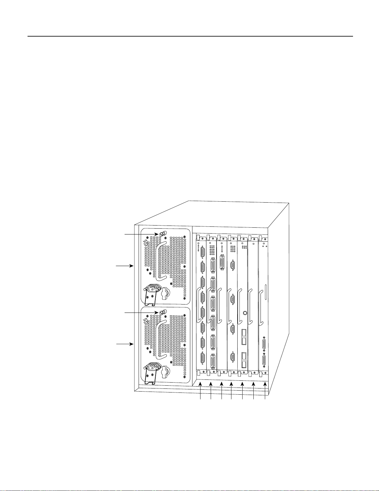
All of the components you will move to the new chassis are accessible from the rear ofthe chassis.
The descriptions that follow assume that you are viewing the chassis from the rear, or
interface-processor end, which is the orientation of the Cisco 7000 shown in Figure 1 or the
Cisco 7507 shown in Figure 2.
Figure 1 Cisco 7000 Chassis Rear View
Captive
installation screw
Upper
power supply
Captive
installation screw
Lower
power supply
DC FAIL
AC POWER
DC FAIL
AC POWER
I
O
H2358
I
O
Slot 0
2
1
3 4 SP
or
RP
slot
SSP
slot
2 Cisco 7000 and Cisco 7507 Chassis Replacement Instructions
Page 3
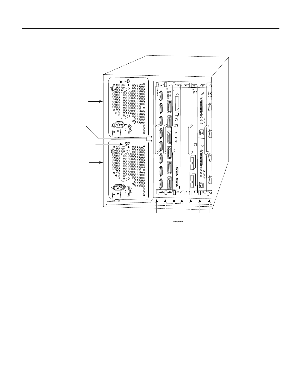
Figure 2 Cisco 7507 Chassis Rear View
aptive
stallation screw
pper
ower supply
DC FAIL
AC POWER
NORMAL
Product Overview
ENABLE
hassis
rounding
ceptacles
aptive
stallation screw
ower
ower supply
DC FAIL
AC POWER
I
O
I
O
Slot 0
EJECT
SLOT 1
SLOT 0
MASTER
SLAVE
SLAVE/MASTER
CPU HALT
RESET
AUX.
ROUTE SWITCH PROCESSOR 2
CONSOLE
2
1
34 5 6
ENABLE
H3888
RSP slots
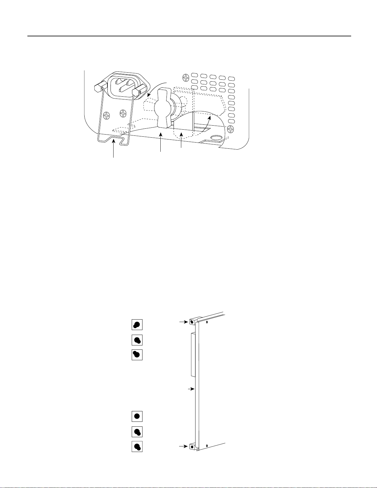
The lower power supply bay is the default bay for systems with a single supply. The upper bay
houses thesecond power supplyin systemswith redundantpower.Power suppliesslide intothe bays
and must be fully inserted before the power switch can be turned on. On each power supply, the
on/off switch prevents the power supply from being removed from the chassis when the power
supply switch (labeled O forthe off position, and | forthe on position) is in the on (|)position. (See
Figure 3.) When the switch is on, a metal tab extends into a slot in the chassis. When the switch is
turned off (O), the tab is raised and clears the slot. A captive installation screw at the top of each
supply secures the supply in the bay and provides grounding for the system.
Cisco 7000 and Cisco 7507 Chassis Replacement Instructions 3
Page 4
Product Overview
Figure 3 Power Supply Safety Interlocks
I
O
H1315a
Locking device
in ON and
locked positions
Cable-retention clip
Safety interlock
switch
To the rightof the powersupply bays, the processorslots house the processormodules. In the Cisco
7000, theRP isalwayslocated inthe farright slot(the RPslot), andthe SP(or SSP)is alwayslocated
in the adjacent slot. The remaining five interface processor slots, numbered 0–4 from left to right,
support anycombination of network interfacetypes: serial, FDDI,Ethernet, and Token Ring, andso
forth.
In the Cisco 7507, the RSP2 is always located in slot 2 or 3. The remaining six interface processor
slots, numbered 0 and 1 and 4 through 6, from left to right, support any combination of network
interface type.
The processormodules slideinto theslots andconnect directlyto thebackplane. Thebackplane slots
are keyed to guides on each type of board. (See Figure 4 for the Cisco 7000 and Figure 5 for the
Cisco 7507.) The keys ensure that the processor modules can be installed only in their designated
slots.
Figure 4 Cisco 7000 System Backplane Slot Key Guides
Key guides on interface
processors, RP and SP (or SSP)
Top
Interface processor
slots 0–5
Top
key guide
SSP (or SSP)
RP
Rear of
processor card
Bottom
Interface processor
slots 0–5
SSP (or SSP)
RP
Bottom
key guide
4 Cisco 7000 and Cisco 7507 Chassis Replacement Instructions
H3144
Page 5
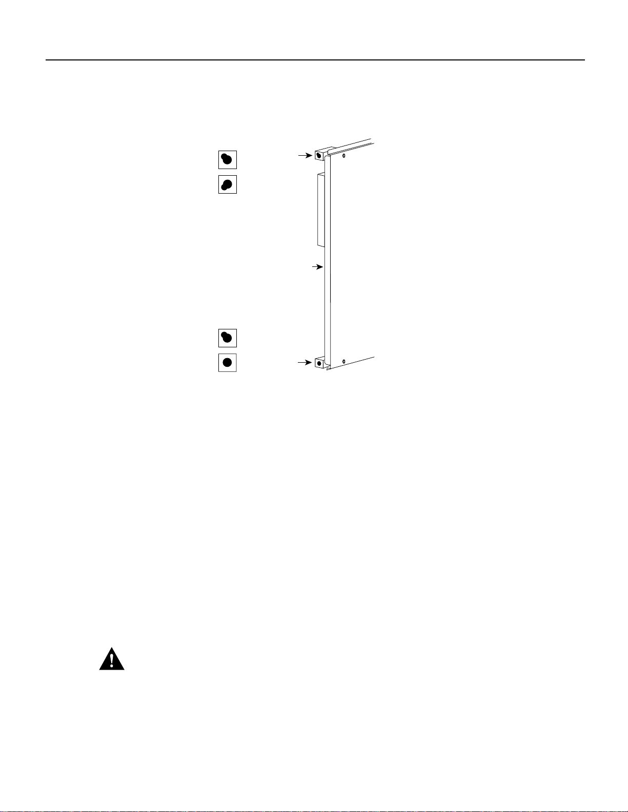
Figure 5 Cisco 7507 System Backplane Slot Key Guides
Key guides on interface
processors and RSP2
Top
RSP2
Top
key guide
Product Overview
Interface processor
Interface processor
slots
RSP2
slots
Bottom
Rear of
processor card
Bottom
key guide
H3126
Spring-loaded ejectorlevers helpto ensure thatthe processormodules are eitherfully inserted inthe
backplane or fully dislodged from it. It is particularly important to use the ejector levers when
removing or installing processor modules because the bus connectors on the boards must be either
fully inserted in the backplane or fully dislodged from it when the system is operating. Any
processor module that is only partially connected to the backplane can hang the bus.
Captive installation screws at the top and bottom of each processor module faceplate, when
tightened, provide EMI shielding and also help ensure proper seating in the backplane. (See
Figure 8.) After using the ejector levers to install a processor module, tighten the top and bottom
captive installation screws to prevent the module from becoming partially dislodged from the
backplane. These screws must be tightened to meet EMI specifications.
For complete descriptionsof all system components, refer tothe Cisco 7000 Hardware Installation
and Maintenance or Cisco 7507 Hardware Installation and Maintenance publications.
Figure 8 on page 19 shows a detail ofthe bottom ejector lever function. Whenyou push the bottom
ejector leverupward, andpush thecorresponding topejector leverdownward,the ejector levers push
the board connectors into the backplane at the rear of the slot inside the chassis. Push the bottom
ejector lever a full 90 degrees upward, and push the upper ejector lever 90 degrees downward, to
ensure that the board connectors are fully seated in the backplane.
Caution The ejector levers ensure that the backplaneconnectors on the card are fully seatedin, or
fully ejectedfrom, the backplane. Failureto use theejector levers couldresult in a partialbackplane
connection, which can hang the system.
Cisco 7000 and Cisco 7507 Chassis Replacement Instructions 5
Page 6

Prerequisites
Prerequisites
Before you move a chassis or any of the system components, review the safety guidelines and
requirements in this section and ensure that you have the necessary parts and tools you will need.
Warning Thiswarning symbol meansdanger. You arein a situationthat could causebodily injury.
Before you work on any equipment, be aware of the hazards involved with electrical circuitry and
be familiar with standard practices for preventing accidents.
Waarschuwing Dit waarschuwingssymbool betekent gevaar. U verkeert in een situatie die
lichamelijk letselkan veroorzaken.Voordat uaan enige apparatuurgaat werken, dientu zichbewust
te zijn van de bij elektrische schakelingen betrokken risico's en dient u op de hoogte te zijn van
standaard maatregelen om ongelukken te voorkomen.
Varoitus Tämävaroitusmerkkimerkitsee vaaraa. Olettilanteessa,joka voijohtaaruumiinvammaan.
Ennen kuin työskentelet minkään laitteiston parissa, ota selvää sähkökytkentöihin liittyvistä
vaaroista ja tavanomaisista onnettomuuksien ehkäisykeinoista.
Attention Ce symbole d'avertissement indique un danger. Vous vous trouvez dans une situation
pouvant causer des blessures ou des dommages corporels. Avant de travailler sur un équipement,
soyez conscient des dangers posés par les circuits électriques et familiarisez-vous avec les
procédures couramment utilisées pour éviter les accidents.
Warnung Dieses Warnsymbol bedeutet Gefahr. Sie befinden sich in einer Situation, die zu einer
Körperverletzungführen könnte. Bevor Siemit derArbeit anirgendeinem Gerätbeginnen, seien Sie
sich der mit elektrischen Stromkreisen verbundenen Gefahren und der Standardpraktiken zur
Vermeidung von Unfällen bewußt.
Avvertenza Questo simbolo di avvertenza indica un pericolo. La situazione potrebbe causare
infortuni alle persone. Prima di lavorare su qualsiasi apparecchiatura, occorre conoscere i pericoli
relativiai circuitielettrici edessere alcorrentedelle pratichestandard perla prevenzione di incidenti.
Advarsel Dette varselsymbolet betyr fare. Du befinner deg i en situasjon som kan føre til
personskade. Før du utfører arbeid på utstyr, må du vare oppmerksom på de faremomentene som
elektriskekretser innebærer,samt gjøredeg kjentmed vanlig praksisnår detgjelder åunngå ulykker.
Aviso Este símbolo de aviso indicaperigo. Encontra-se numasituação que lhepoderá causar danos
físicos. Antes de começar a trabalhar com qualquer equipamento, familiarize-se com os perigos
relacionados com circuitos eléctricos, e com quaisquer práticas comuns que possam prevenir
possíveis acidentes.
¡Advertencia! Este símbolo de aviso significa peligro. Existe riesgo para su integridad física.
Antes de manipular cualquier equipo, considerar los riesgos que entraña la corriente eléctrica y
familiarizarse con los procedimientos estándar de prevención de accidentes.
Varning! Denna varningssymbol signalerar fara. Du befinner dig i en situation som kan leda till
personskada. Innan du utför arbete på någon utrustning måste du vara medveten om farorna med
elkretsar och känna till vanligt förfarande för att förebygga skador.
6 Cisco 7000 and Cisco 7507 Chassis Replacement Instructions
Page 7
Safety Guidelines
Prerequisites
The following guidelines will help to ensure your safety and protect the equipment. This list is not
inclusive of all potentially hazardous situations, so be alert.
Warning Before working on a system that has an on/off switch, turn OFF the power and unplug
the power cord. (For translations of this safety warning, refer to the section “Power Disconnection
Warning” on page 36.)
Warning Do not touch the power supply when the power cord is connected. For systems with a
power switch, line voltages are present within the power supply even when the power switch is off
and the power cord is connected. For systems without a power switch, line voltages are present
within the power supply whenthe power cord isconnected. (For translations ofthis safety warning,
refer to the section “Power Supply Warning” on page 36.)
Warning Before working on a chassis or working near power supplies, unplug the power cord on
AC units; disconnect the power at the circuit breaker on DC units. (For translations of this safety
warning, refer to the section “Power Supply Disconnection Warning” on page 37.)
Warning This unit might have more than one power cord. To reduce the risk of electric shock,
disconnect the two power supply cords before servicing the unit. (For translations of this safety
warning, refer to the section “Electric Shock Warning” on page 38.)
• Never try to lift the chassis by yourself; two people are required to lift the chassis.
• Use a hand truck or pallet jack to move the chassis between locations.
• Always disconnect all power cords and interface cables before moving the chassis.
• Keep tools and chassis components away from walk areas.
• Do not work alone when potentially hazardous conditions exist.
• Do not perform any action that creates a potential hazard to people or makes the equipment
unsafe.
• Carefully examine your work areafor possible hazards such as moist floors, ungrounded power
extension cables, and missing safety grounds.
Cisco 7000 and Cisco 7507 Chassis Replacement Instructions 7
Page 8
Prerequisites
Lifting the Chassis Safely
The chassis weighs 76pounds when empty (no processor modules or power supplies installed) and
145 pounds when fully configured with two power supplies and all interface slots populated.
Whenever you lift the chassis or any heavy object, follow these guidelines:
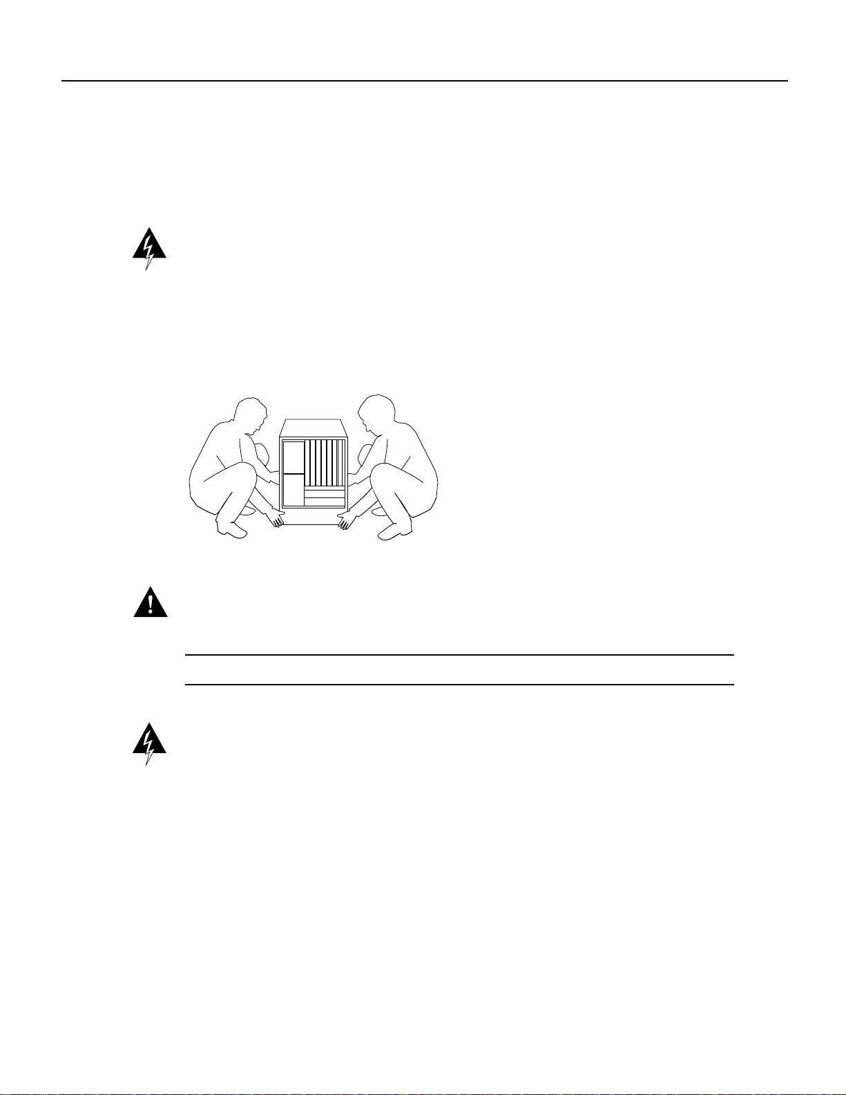
Warning Two people are required tolift the chassis. Grasp the chassis underneath the lower edge
and lift with both hands.To prevent injury, keep your back straightand lift with your legs, not your
back. To prevent damage to the chassis and components, never attempt to lift the chassis with the
handles on thepower supplies or on theinterface processors, or by theplastic panels on the front of
the chassis. These handles were not designed to supportthe weight of the chassis. (For translations
of this safety warning, refer to the section “Chassis Lifting Warning” on page 39.)
Figure 6 Lifting Safely
H2336
Caution To prevent damage,neverattempt tolift thechassis withthe handleson thepower supplies
or the interface processors. These handles are not designed to support the weight of the chassis.
Note The following warning is for units equipped with DC-input power supplies.
Warning Before performing any of the following procedures, ensure that power is removed from
the DC circuit. To ensure that all power is OFF, locate the circuit breaker on the panel board that
services theDC circuit, switch thecircuit breaker tothe OFF position,and tape the switchhandle of
the circuit breaker in the OFF position. (For translations of this safety warning, refer to the section
“DC Power Disconnection Warning” on page 40.)
• Remove all power supplies before lifting the chassis. Each supply weighs 20 pounds.
• Always disconnect all external cables before lifting or moving the chassis.
8 Cisco 7000 and Cisco 7507 Chassis Replacement Instructions
Page 9
Safety with Electricity
Prerequisites
Follow these basic guidelines when working with any electrical equipment:
• Before beginning any procedures, locate the emergency power-off switch forthe room in which
you are working.
• Never assume that power has been disconnected from a circuit; always check.
• Always disconnectall cables (including network interface andtelephone wiring) andremove all
power supplies before moving or lifting the chassis.
Warning Always disconnect all cables before moving or working on the chassis. Even when the
chassis is disconnected from all power sources, telephone wiring can still deliver potentially lethal
electrical surges.
• Never install telephone wiring during a lightning storm.
Warning Do not work on the system or connect or disconnect cables during periods of lightning
activity. (For translations of this safety warning, refer to the section “Lightning Activity Warning”
on page 41.)
• Never install telephone jacks in wet locations unless the jack is specifically designed for wet
• Never touch uninsulated telephone wires or terminals unless the telephone line has been
• Use caution when installing or modifying telephone lines.
Cable Strain Relief
If possible,position thenew replacementchassis close enoughto the existing systemso thatyou can
avoidhaving todisconnect powerand interface cables.Be sure to disengage anystrain reliefdevices
before attempting to pull the cables from the port. Following are descriptions of the different
methodsof strainrelief thatare usedon thepowersupplies andthe varioustypes ofnetworkinterface
ports:
• On the AC-input power supplies, a cable retention clip snaps up around the connector on the
• On the DC-input power supplies, two nylon cable ties provide strain relief for the DC-input
• Serial interface cables (alltypes) use thumbscrews on the cableconnectors that secure the cable
locations.
disconnected at the network interface.
power cord to prevent it from being inadvertently pulled out of the power supply port. Before
attempting to disconnect the power cord, be sure topush the retention clip down away from the
cable connector.
cables.
to the FSIP port.
• Ethernet interface cables use either slide-type locks or thumbscrews. The Ethernet Interface
Processor (EIP) ports are shipped from the factory with slide-type locks on each port; however,
a conversion kit is also shipped for replacing the slide-type locks with jackscrews to
accommodate Ethernet interface cables with thumbscrews.
Cisco 7000 and Cisco 7507 Chassis Replacement Instructions 9
Page 10

Prerequisites
• Multimode Fiber Distributed Data Interface (FDDI) connectors use small plastic arms on two
sides ofthe connectorthat actlike springsand areconstrained by theinside ofthe connectorport.
To remove a multimode cable from a FIP port, pinch the two plastic arms inward while pulling
the connector out of the port.
When removing any cable, pull the cable out at the connector; never pull or tug on the cable itself.
For detailed descriptions of the interface connectors and ports, refer to the Cisco 7000 Hardware
Installation and Maintenance or Cisco 7507 Hardware Installation and Maintenance publications.
List of Parts and Tools
You need someor all of thefollowing toolsand parts to performthis replacement procedure.Before
you begin, read through the procedure to determine which tools you need for this replacement
procedure.
• Number 2 Phillips or3/16-inch flat-blade screwdriver forthe captive installationscrews on each
processor module. (Most systems use Phillips screws, but some of the earlier systemsproduced
use slotted screws.)
• A 1/4-inchflat-blade or Number 2Phillips screwdriver toinstall the power supply. Earlier power
supplies (the first few hundred shipped) have a slotted-head captive installation screw.
• ESD-preventionequipment orthe disposable groundingwrist strapincluded withall upgrade kits
• Antistatic mat, foam pad, or bag for removed processor modules in case you are not able to
immediately insert them into the new chassis.
If your chassis is mounted in a rack, you will need the following tools to remove and replace the
mounting hardware:
• Number 2 Phillips screwdriver
• 3/16-inch flat-blade screwdrivers
• Tape measure
• Level
• One 7/16-inch open-end (or adjustable) wrench if you will remove the chassis feet
Preventing Electrostatic Discharge Damage
Electrostatic discharge (ESD) damage, which occurs when electronic boards or components are
improperly handled, can result in complete or intermittent failures. The processor modules each
comprise a printed circuit board thatis fixed in a metal carrier. Electromagnetic interference (EMI)
shielding, connectors,and ahandle are integral componentsof the carrier. TheLED board,however,
isnot intendedto behandled andhas noframe orshielding.Handle theLED boardby theedges only;
never touch the board components, traces, or connector pins.
Caution Always handle an LED board by the edges only; avoid touching the board components,
traces, or connector pins.
10 Cisco 7000 and Cisco 7507 Chassis Replacement Instructions
Page 11
Unpacking the Chassis
Following are guidelines for preventing ESD damage:
• Always use an ESD strap and ensure that it makes good skin contact.
• When removingor installing anLED board, connectthe equipment endof the groundstrap to an
unpainted surface of the chassis, suchas the vertical metal frame that is exposed when thefront
chassis panels are removed.
• Handle boards by the edges only; avoid touching the board components, traces, or connector
pins.
• Place a removed board component-side-up on an antistatic surfaceor in a staticshielding bag. If
you are returning the board tothe factory, immediately placeit in a static shielding bag to avoid
ESD damage.
• Avoid contactbetween the boardand clothing. Thewrist strap only protectsthe board fromESD
voltages on the body; ESD voltages on clothing can still cause damage.
Caution Forsafety,periodically checkthe resistancevalue ofthe antistaticstrap. Themeasurement
should be within the range of 1 and 10 megohms.
Preparing the Work Area
Althoughsome networkdowntime isunavoidablewhile youremove theRP andSP andreplacethem
in the new chassis, you can minimize network downtime by placing the old and new chassis close
together.If your existingchassis is mounted ina rack, and thereis space in thesame rack or another
rack close by, install the new chassis in the rack before shutting down the existing chassis. Leave
network interface cables connected to the interface ports only if the following conditions are true:
• You are able to place the new chassis next to the existing chassis, and moving the processor
modules to the new chassis will not strain the interface cables.
• You will not have to lift the new chassis after the processor modules and power supplies are
installed.
• The new chassis is already located in its permanent location, or you will need to move it only a
few feet into the space vacated by the old chassis when it is removed.
• Before removing anexisting chassis that israck mounted, you are ableto install the new chassis
in the same rack or an adjacent rack, and moving theprocessor modules to the new chassis will
not strain the interface cables.
If these conditionsare not true, for instance,if you must remove a rack-mountedchassis before you
can install the new chassis, you must disconnect all power and network interface cables.
Unpacking the Chassis
To unpack the new chassis, follow the directions in the document Cisco 7000 and Cisco 7507
Unpacking Instructions (DocumentNumber 78-1067-xx), which ships with every newchassis; this
document is also available on UniverCD.
Replacing a Rack-Mounted Chassis
This section describes how to replacethe chassis in a system that is installed in an equipment rack.
The order in which you remove the existing system, install the new chassis, and replace the
components will vary depending upon the space available in the rack and in the work area. Assess
your rack and lab configuration and choose the appropriate replacement plan from the following:
Cisco 7000 and Cisco 7507 Chassis Replacement Instructions 11
Page 12
Replacing a Rack-Mounted Chassis
• If there is sufficient space available in the same rack (or an adjacent rack) to install the
replacement(empty) chassisbefore youremovethe existingsystem, youcanminimize downtime
and avoidhaving to disconnectnetwork interfacecables byleaving theexisting systemoperating
whileyou installthe replacementchassis inthe rack.Justensure thatboth chassis,when installed,
will beclose enoughto avoidstraining cablesconnected tothe interfaceprocessors. If thisoption
is possible, proceed to the section “Adding a New Chassis to the Rack.”
• If sufficient rack space is not available to install both chassis (if you must remove the existing
system from therack to make room for thereplacement chassis), you will have to disconnect all
network interface cables and remove the power supplies before removing the existing system
from the rack. Be sure to label the interface cables to avoid crossing them when you reconnect
them tothe interface ports.As you disconnectcables from theinterface processors, completethe
configuration worksheetprovided atthe end ofthis document tohelp you reconnectthe cables to
the correct ports. (For the Cisco 7000, refer to Figure 17, and for the Cisco 7507, refer to
Figure 18.)
• If the existing system is installed in an enclosed rack, or if a power strip or other rack fixture
blocks access to the power supply bays, you may have to remove the existing system with the
power supplies intact and then install them in the replacement chassis before you install that
chassis in the rack.If you must choose this method,ensure that you have sufficient assistance to
lift and support the chassis and the rack. The chassis weights over 100 pounds with two power
supplies installed, and the rear of the chassis is heaviest.
Note Be sure that you have sufficient help (assistants) to lift and support the chassis and the rack
when performing these procedures. The empty replacement chassis weights 75 pounds. A fully
configured chassis weighs 145 pounds. Whenever possible, remove all power supplies before
moving or lifting the chassis.
Warning Two people are required tolift the chassis. Grasp the chassis underneath the lower edge
and lift with both hands.To prevent injury, keep your back straightand lift with your legs, not your
back. To prevent damage to the chassis and components, never attempt to lift the chassis with the
handles on thepower supplies or on theinterface processors, or by theplastic panels on the front of
the chassis. These handles were not designed to supportthe weight of the chassis. (For translations
of this safety warning, refer to the section “Chassis Lifting Warning” on page 39.)
12 Cisco 7000 and Cisco 7507 Chassis Replacement Instructions
Page 13
Adding a New Chassis to the Rack
If there is sufficient rack space to install the replacement chassis before you remove the existing
system, proceed as follows.
Step 1 Follow the instructions in the section “Unpacking the Chassis” on page 11 to unpack the
rack mounting hardware and, after the mounting hardware is installed, to unpack the
chassis.
Step 2 Ensurethat there are atleast 20 inches of verticalspace free in therack above or below the
existing system, or in a nearby rack, in which to install the replacement chassis.
Warning To prevent bodily injury when mounting or servicing this unit in a rack, you must take
special precautions to ensurethat the system remains stable. The followingguidelines are provided
to ensure your safety:
— This unit should be mounted at the bottom of the rack if it is the only unit in the rack.
— When mounting this unit in a partially filled rack, load the rack from the bottom to the top
with the heaviest component at the bottom of the rack.
— If the rack is provided with stabilizing devices, install the stabilizers before mounting or
servicing the unit in the rack. (For translations of this safety warning, refer to the section
“Chassis Warning—Rack-Mounting and Servicing” on page 42.)
Replacing a Rack-Mounted Chassis
Warning Do not use a ramp inclined at more than 10 degrees. (For translations of this safety
warning, refer to the section “Ramp Warning” on page 44.)
Step 3 Follow the instructions in the Cisco 7000 and Cisco 7507 Rack-Mount Kit Installation
Instructions (Document Number 78-1058-xx), which is included with the rack- mounting
hardware, to install the mounting hardware and replacement chassis in the rack.
Step 4 When the replacement chassis is secured in the rack, turn off all power supplies in the
existing system.
Step 5 Proceed to the section “Moving System Components” on page 18 to move the power
supplies and processor modules to the new chassis.
Caution When removing and replacing interface processors, be careful not to strain or bend
network interface cables.
Step 6 When all of the components are moved to the new chassis, ensure that all of the captive
installation screws on the power supplies and all interface processors are tightened.
Step 7 Proceedto the section“Verifying the Installation”on page 24to verify thatall components
are installed correctly.
Step 8 To remove the old chassis (which should now be empty), use a 1/4-inch flat-blade
screwdriver to loosen the four binder-head screws that secure the left and right ears to the
front mounting strips on the equipment rack. (See Figure 7).
Cisco 7000 and Cisco 7507 Chassis Replacement Instructions 13
Page 14
Replacing a Rack-Mounted Chassis
Caution To prevent damage,never attemptto lift orsupport the frontof the chassiswith the plastic
front panels. The panels can break away and allow the chassis to drop.
Step 9 To remove the empty chassis from the rack, position one person in the back of the rack to
push the chassis out the front, and position two people in front of the rack to support the
chassis as it is pushed forward out of the rack.
Caution The following step might shift the chassis’ center of gravity to the front of the rack and
may cause the rack or the chassis to tip or fall. Before proceeding, ensure that you have sufficient
assistance to prevent the rack from toppling and the chassis from falling out of the rack.
Step 10 Slowly push the chassis out of the front of the rack while the two assistants in the front of
the rackgrasp the chassis alongthe metal undersidesbehind the plastic frontpanels. When
the chassis is clear of the rack, lower it to the floor.
Step 11 Follow the safety guidelines in the section “Lifting the Chassis Safely” on page 8, and
remove the empty chassis from the area.
Replacing the Existing Rack-Mounted Chassis
If sufficient rackspace isnot available toinstall bothchassis (ifyou mustremove theexisting system
from the rack to make room for the replacement chassis), you will have to disconnect all network
interface cables and remove the powersupplies before removing the existing system from therack.
Be sureto labelthe interface cables to avoid crossingthem whenyou reconnect themto theinterface
ports. Asyou disconnectcables fromthe interfaceprocessors, complete theconfiguration worksheet
to help you reconnect the cables to the correct ports.
Step 1 Usethe configuration worksheetprovided at the endof this document oryour own method
to label the interface cables and record the port connection for each cable. (For the Cisco
7000, refer to Figure 17, and for the Cisco 7507, refer to Figure 18.)
Step 2 Turn all power supplies OFF.
Note The following warning is for units equipped with DC-input power supplies.
Warning Before performing any of the following procedures, ensure that power is removed from
the DC circuit. To ensure that all power is OFF, locate the circuit breaker on the panel board that
services theDC circuit, switch thecircuit breaker tothe OFF position,and tape the switchhandle of
the circuit breaker in the OFF position. (For translations of this safety warning, refer to the section
“DC Power Disconnection Warning” on page 40.)
Step 3 Afterreviewing thedescriptions in the section“Cable Strain Relief” on page9, disconnect
all power and network interface cables from the rear of the existing system.
14 Cisco 7000 and Cisco 7507 Chassis Replacement Instructions
Page 15

Replacing a Rack-Mounted Chassis
Caution If the existing chassis is installed in an enclosed rack, or if a power strip or other rack
fixture blocks access to the power supply bays, you might have to remove the existing system with
the power supplies intact, and then install them in the replacement chassis before you install that
chassis in the rack. Ensure that you have sufficient assistance to support the chassis and to prevent
the rack from tippingwhile you move the chassisinto or out of the rack.A fully-configured chassis
weighs 145 pounds, and the rear of the chassis is heaviest.
Step 4 Remove all power supplies from the existing system and place them aside (leave the
processor modules installedin the chassis.) Referto the section “Moving Power Supplies”
on page 21
Cisco 7000 and Cisco 7507 Chassis Replacement Instructions 15
Page 16

Replacing a Rack-Mounted Chassis
Step 5 Onthe frontof therack, use a1/4-inch flat-bladescrewdriver toloosen andremove thefour
binder-head screws that secure the left and right ears to the front mounting strips on the
equipment rack. (See Figure 7.) Keep the removedscrews together; you will need them to
secure the replacement chassis in the rack.
Figure 7 Rack Mounting Hardware
Bracket
Chassis ear with
captive sliding
H2292
grommets
Warning
M4 x 10-mm long Phillips
flat-head screws (to attach
ears to chassis)
The following step might shift the chassis’ center of gravity to the front of the rack and
10-32 x 5/8-inch long Phillips
pan-head screws with integral
square cone washers
(for mounting brackets and
chassis ears to rack posts)
may cause the rack or the chassis to tip or fall. Before proceeding, ensure that you have sufficient
assistance to prevent the rack from toppling and the chassis from falling out of the rack. Never
attempt to lift or support the front of the chassis with the plastic front panels.The panels can break
away and allow the chassis to drop.
16 Cisco 7000 and Cisco 7507 Chassis Replacement Instructions
Page 17

Replacing a Rack-Mounted Chassis
Step 6 Position one person in the back of the rack to push the chassis out the front, and position
two peoplein front of therack to supportthe chassis and lower it to thefloor as it is pushed
forward out of the rack. Slowly push the chassis out of the front of the rack while the two
assistants in the front of the rack grasp the chassis along the metal undersides behind the
plastic front panels. When the chassis is clear of the rack, lower it to the floor.
Step 7 Positionthe removedchassis sothat you willhave roomat the rearof the chassisto remove
the processor modules, and ensure that it will not be in the way when you install the
replacement chassis in the rack.
Step 8 Usea Number 2 Phillips screwdriver to remove the chassis ears from theremoved chassis
and install them on the replacement chassis in the same position. Figure 7 shows the ears
mounted on the front of the chassis; if you are installing the system with the rear of the
chassis facing out of the front of the rack, use the mounting holes nearest the edge of the
ears (farthest from the bend) to mount them to the chassis.
Warning If you must lift the new chassis with the power supplies installed, ensure that you have
sufficient assistance to lift the chassis and support the rack. A fully configured chassis weighs
145 pounds, and the rear of the chassis is heaviest.
Step 9 With one person positioned on each sideof the replacementchassis, grasp the undersideof
the chassisbehind thefront plastic panelsand liftthe replacement chassisup untilit is level
with the rails in the rack.
Step 10 Insert the rear of the chassisinto the rack and lower it until the bottom of the chassis rests
on the rails.
Step 11 Slide the chassis back into the rack until the ears on the chassis are flush against the front
mounting strip on the rack.
Step 12 Use the four binder-head screws you removed in Step 5 to secure the ears to the front
mounting strip on the rack. (See Figure 7).
Step 13 Proceed to the section “Moving System Components” on page 18 to move the power
supplies and processor modules to the new chassis.
Caution When removing and replacing interface processors, be careful not to strain or bend
network interface cables.
Step 14 Whenall of the componentsare moved tothe newchassis, reconnect all interfacecables to
the interface ports. Ifyou filled out the configuration worksheet, use it asa guideline. (For
the Cisco 7000, refer to Figure 17, and for the Cisco 7507, refer to Figure 18.)
Step 15 Proceedto the section “Verifyingthe Installation” onpage 24 to verify thatall components
are installed correctly.
Cisco 7000 and Cisco 7507 Chassis Replacement Instructions 17
Page 18

Moving System Components
Moving System Components
The following sections describe the procedures for removing each processor module and power
supply from the old chassis and installing it in the new chassis. Move and install all processor
modules before you move the power supplies. If you removed your existing chassis from an
equipment rack, the powersupplies should already be removed; however,do not install them in the
replacement chassis until all processor modules are installed. Each interface processor slot in the
replacement chassis contains a blank board carrier. Remove the blank carriers individually as you
prepare to move each interface processor from the corresponding slot in the existing chassis.
If you are able to place both chassis close enough to avoid straining the connected interface cables
when you move the interface processors to the new chassis, you can leave the interface cables
connected. If you must disconnect the cables, label each cable with its slot and port number before
you disconnect it. You can alsouse the optional configuration worksheet provided at the endof this
document to record the cable positions. (For the Cisco 7000, refer to Figure 17, and for the Cisco
7507, refer to Figure 18.)
Caution Be sure to wear an ESD-prevention device while performing these steps. Review the
guidelines in the section “Preventing Electrostatic Discharge Damage” on page 10 if necessary.
Step 1 Place the existing and replacement chassis side by side, if possible, and ensure that your
path between the two chassis is unobstructed.
Step 2 Slipon agrounding strap orother ESD-preventiondevice andattach it toone ofthe captive
installation screwson a power supply inthe rear of the chassis. (SeeFigure 1 or Figure 2.)
If you already removed the power supplies, clip the ESD-preventive strap to the captive
screw on any unfinished chassis surface.
Step 3 On the existing system, turn all power supply switches OFF (O) if you have not already
done so.
Step 4 On each interface cable connected to an interface processor, check the available slack to
determine whether removing the interface processor will strain the cable. Do not risk
straining the cables; if you are not sure if there is enough slack in the cable, disconnect it
before removing the interface processor.
Step 5 Checkthe slack on cables thatare connected to the RP(in the Cisco 7000) orRSP2 (in the
Cisco 7507) console or auxiliary ports and also disconnect those cables if necessary.
Step 6 If you must disconnect the cables, label each one and use the configuration worksheet at
theend ofthis documentto recordthe portconnections ofeach cableto avoid crossingthem
when you reconnect them to the new chassis. (For the Cisco 7000, refer to Figure 17, and
for the Cisco 7507, refer to Figure 18.) The section “Cable Strain Relief” on page 9
describes the different methods of strain relief used on the various interface types.
Moving the Processor Modules
Before removing any of the processor modules from the existing chassis, ensure that all system
power is off. Do not turn on the power for the replacement chassis until you have verified that all
components are installed properly.
After looseningthe captiveinstallation screws,use the ejectorlevers toremove andinstall processor
modules. The ejectorlevers help toensure that backplane connectorson the card are fully seated in,
or fully ejected from, the backplane. (Refer to the ejector lever description on page 5.)
18 Cisco 7000 and Cisco 7507 Chassis Replacement Instructions
Page 19

Moving System Components
Failureto use theejector leverscould result ina partialbackplane connectionand subsequentsystem
crash. Also,be sure totighten both the topand bottom captive installationscrews oneach module to
ensure that it will remain seated properly. When replacing components, work from right to left.
When you remove a processor module, immediatelyinstall it in the newchassis and secure it in the
identical slotbefore removing thenext processor module.Before removing processormodules, first
remove theblank board carrier from thecorresponding slot in thenew chassis so thatyou can move
the processor module directly into the same slot in the new chassis.
Follow these steps to move the processor modules to the new chassis:
Step 1 Use a screwdriver (Number 2 Phillips or 1/4-inch flat-blade) to loosen the captive
installation screws at the top and bottom of the faceplate. (See Figure 8a).
Figure 8 Bottom Ejector Lever and Captive Installation Screw
a
Processor
module
carrier guide
Captive
installation
screw
b
Bottom ejector lever
Processor module
slot
c
Stop
immediately
on contact
Cisco 7000 and Cisco 7507 Chassis Replacement Instructions 19
H1482a
Page 20

Moving System Components
Step 2 Place your thumbs on the upper and lower ejector levers and simultaneously push the top
Step 3 Grasp the carrier handle with one hand and place your other hand under the carrier to
Figure 9 Handling a Processor Module During Installation
leverup andthe bottom lever down to releasethe boardconnector from thebackplane. (See
Figure 8c.)
support and guide it out of the slot. (See Figure 9.) Avoid touching the board or any
connector pins.
H1355a
Step 4
Carefully pull the carrierstraight out of the slot, keepingyour other hand under the carrier
to guide it. (See Figure 9.) Keep the carrier at a 90-degree orientation to the backplane.
Immediately proceed to thefollowing step to install theremoved board in thereplacement
chassis.
Caution In the Cisco 7000, you must install the RP in the slot labeled RP, and the SP (or SSP) in
the slot labeled SP. The RP slot is the far right slot when viewing the chassis from the rear, and the
SP slot is immediately to the left of the RP. The interface processors can be installed in any of the
interface processor slots, labeled0-4. The slots are keyed forcorrect installation. Forcing the RP or
SP into the wrong slot can damage the backplane and board connectors.
In theCisco 7507, you mustinstall the RSP2 inslot 2 or 3.The interface processors can be installed
in any of the interface processor slots, labeled 0 and 1, and 4 through 6. The slots are keyed for
correct installation. Forcing a processor module into the wrong slot can damage the backplane and
board connectors.
Step 5 Place the back of the carrier in the appropriate slot in the new chassis and align the notch
on the top and bottom of the carrier with the groove in the top and bottom of the chassis
slot. (See Figure 8a and Figure 8b).
20 Cisco 7000 and Cisco 7507 Chassis Replacement Instructions
Page 21

Moving System Components
Step 6 While keeping the carrier at a 90-degree orientation to the backplane, carefully slide the
carrierinto theslot untilthe backof thefaceplatemakes contactwith theejector levers.(See
Figure 8b.)
Step 7 Usingthe thumb and forefinger of each hand, simultaneouslypush the top lever down and
the bottom lever up 90 degrees to fully seat the board connectors in the backplane. (See
Figure 8c.)
Caution Do notuse unnecessaryforce when installingprocessor modules. Always guidethe board
carrier into the slot only until the carrier faceplate is flush against the ejector lever, then use the
ejector levers to pushthe interface processor fully intothe slot and seat itin the backplane properly.
Step 8 Use a screwdriver (Number 2 Phillips or 1/4-inch flat-blade) to tighten the captive
installation screws on the top and bottom of the faceplate. (See Figure 8).
Step 9 RepeatSteps 1 through 8for each remaining processormodule, working from rightto left.
Before removing a processor module from the existing chassis, remove the blank board
carrier from the corresponding slot in the replacement chassis. Try to replace interface
processors in the same slot number you removed them from to avoid confusion when
reconnecting cables and checking the installation.
Step 10 Proceed to the next section to move the power supplies.
Note Leave the blank board carriers installed in all unfilled interface processor slots.
Moving Power Supplies
You can insert the power supplies and connect the power cables, but do not turn on system power
until you are ready to restart the system and check the installation. Always install the first power
supply in thelower power supply bayand the second, if any, in the upper bay. Remember to tighten
the captive installation screw on the top of each power supply. The screw prevents the supply from
becoming dislodged from the power connections inside the chassis and also provides proper
grounding for the system.
Follow these steps to move a power supply:
Step 1 If you have already removed all power supplies, proceed to Step 7.
Step 2 Ensure that the switch on each power supply is turned fully to OFF (O), then disconnect
Step 3 Disconnect the power cable from each power source.
Step 4 Disconnect the power cable from each power supply.
Step 5 Usea screwdriverto loosen the captive installationscrew on the power supply in the lower
all power cords from the power sources.
bay.
Step 6 Grasp the power supply handle and pull the supply out of the bay. Place one hand
underneath tosupport thebottom ofthe supplyas youpull itout ofthe bay. (SeeFigure 10.)
Immediately proceed to the following step to install the removed power supply in the
replacement chassis.
Cisco 7000 and Cisco 7507 Chassis Replacement Instructions 21
Page 22

Moving System Components
Note Use bothhands to handlepower supplies.Each weighs20 pounds. Ifthe powersupply resists
when you attempt to pull it out of the bay, the switch is probably not fully in the OFF (O) position,
or the captive installation screwat the top ofthe supply is notfully loosened. Turnthe power switch
fully counterclockwise to OFF (O), and check the captive installation screw, then try removing the
supply again.
Figure 10 Handling a Power Supply (AC-Input Power Supply Shown)
Captive
installation
screw
Step 7
DC FAIL
AC POWER
H1356a
I
0
Fill the lower power supply bay first. Insert the rear of the power supply into the bay and
align it so that it will go straight into the bay.
Step 8 Pushthe power supply all the wayinto the bay. Do notuse unnecessary force; firmly push
the supply back into the bay until the power supply front panel is flush against the chassis
rear panel.
Caution When inserting a power supply into the bay, do not useunnecessary force; slamming the
powersupply into thebay candamage the connectorson therear of the supply andinside thechassis.
Step 9 Use a screwdriver to tighten the captive installation screw on the top of the power supply.
Caution Alwaystighten the captive installationscrew atthe topof the powersupply beforeturning
on the power switch. This screw prevents the power supply from shifting away from the internal
connector and provides proper grounding for the supply.
Step 10 If you are removing or installing a second power supply, use a screwdriver to remove the
cover plate from the upper power supply bay. Store the removedcover plate and replace it
whenever the system is operating with one power supply.
Step 11 Repeat Steps 2 through 9 for the second power supply, if any.
Step 12 On each power supply in the new chassis, push the cable retention clip down, away from
the power cord port, and plug in the power cord.
22 Cisco 7000 and Cisco 7507 Chassis Replacement Instructions
Page 23

Moving System Components
Step 13 To secure the AC-input cable in the power supply AC receptacle, push up the cable
retention clip up until it snaps into place around the connector.
To secure the DC-input cable to the power supply, attach the three leads to the terminal
block, and thenattach two nyloncable ties around theDC-input cable and thebracket near
the terminal block. (See Figure 11.) Color code depends on your DC source.
Warning Whenstranded wiring isrequired, useapproved wiring terminations,such asclosed-loop
or spade-type with upturned lugs. These terminations should be the appropriate size for the wires
and shouldclamp both theinsulation and conductor. (For translationsof this safetywarning, referto
the section “DC Power Supply Warning” on page 44.)
Warning The illustration shows the DC power supply terminal block. Wire the DC power supply
using the appropriate lugsat the wiring end, as illustrated. Theproper wiring sequence is ground to
ground, positiveto positive (line toL), and negativeto negative (neutralto N). Note that the ground
wire shouldalways beconnected first anddisconnected last. (For translationsof this safetywarning,
refer to the section “DC Power Supply Wiring Warning” on page 45.)
Step 14 Place the terminal block cover over the terminal block and secure it with the two captive
installation screws. (See Figure 11.)
Figure 11 DC-Input Power Supply Cable Connections
DO NOT SHIP WITH POWER SUPPLY
INSTALLED
FASTENER TO BE FULLY ENGAGED
BEFORE OPERATING POWER SUPPLY
Captive installation
OUT FAIL
INPUT POWER
screw
Power leads attached
to terminal block
( ) negative
( ) positive
( ) ground
Nylon ties on cable
and metal bracket
INPUT VOLTAGE : 40-72 V=
Step 15
INPUT CURRENT : 24-13A
Connect the opposite end of each power cable to an appropriate power source.
H2530
Caution Do not turn on any power supplies until you are ready to power up the system. The
interlock switch that locks the power supply in the slot also turns on the system power.
Step 16 Proceedto the section“Verifying the Installation”on page 24to applypower andcheck the
installation.
Cisco 7000 and Cisco 7507 Chassis Replacement Instructions 23
Page 24

Verifying the Installation
Verifying the Installation
This section provides instructions for first ensuring that all connections are secure and then for
restarting the system and verifying that it operates correctly. If the system does not start up and
operate asexpected, the troubleshootingprocedures in this sectionwill help you isolate the cause of
the problem.
Checking Connections
Perform a final installation check of all components and cable connections as follows:
Step 1 Checkthe processor modules to makesure that eachis inserted allthe way intoits slot, and
that both the top and bottom captive installation screws are tightened.
Step 2 Checkthe interfacecable connections tothe interfaceprocessors, and ensurethat all cables
are fully seated in the ports and all strain relief systems are engaged.
Step 3 Ensure that the console cable is secured to the console port on the RP (in the Cisco 7000)
or the RSP2 (in the Cisco 7507), and that the console terminal is turned ON.
Step 4 Check the power supplies for the following:
• Each powersupply is insertedall the wayinto its bay, andthe captiveinstallation screw
on each one is tightened.
Restarting the System
When you have checked all of the connection points, you will restart the system by turning on the
power supplies, andthen verify that the system is operating properly by observing the LEDs on the
rear of the system.
Note The following warning is for units equipped with DC-input power supplies.
Warning Afterwiring theDC powersupply,removethe tapefrom thecircuit breakerswitch handle
and reinstatepower by moving the handleof the circuitbreaker to theON position. (Fortranslations
of this safety warning, refer to the section “DC Power Connection Warning” on page 46.)
Step 1 Turn ONthe lowerpowersupply byturning thepower supplyswitch clockwiseone-quarter
Note Ifthe powersupply switchresists, thepower supplyis probablynot fullyinserted intothe bay.
Turnthe power switch off (fully counterclockwiseto O), pull the power supply outof the bay about
two inches, then push the power supply firmly back into the slot. Do not slam the supply into the
slot; doing so can damage the connectors on the supply and the backplane. Tighten the captive
installation screw before proceeding.
• All power supply cables are inserted into the power supply and secured with the cable
retention clip.
turn. The lower power LED on the front of the chassis will go on.
24 Cisco 7000 and Cisco 7507 Chassis Replacement Instructions
Page 25

Verifying the Installation
Step 2 Afterturning onthe lower power supply, turnON theupper powersupply (ifone ispresent)
for redundant power. The upper power LED on the front of the chassis will go on.
Step 3 While the system initializes, the boot error LED on the RP (or the CPU halt LED on the
RSP2 and RP) goes on for about five seconds or less, then goes out when the boot is
complete. The interface processor LEDs also go on in irregular sequence as the RP (or
RSP2) initializes each one.
Step 4 Afterthe system boots thesoftware and initializes the interface processors (approximately
30 seconds), verify that the RP (or RSP2) LEDs are in the following states:
• Normal LED is on
• CPU halt LED is off (on the RSP2 and RP)
• Boot error LED is off (on the RP)
Step 5 Verify thatall of the enabledLEDs on all interfaceprocessors (and on theSP or SSP in the
Cisco 7000) are on.
Step 6 Verify that the console terminal displays a script and system banner.
When you have verified all of the conditions in Steps 1 through 6, the replacement procedure is
complete, and you can now resume normal operation.
An errorcondition exists ifno indicators go onat power upor after initialization, orif the booterror
or CPUhalt LEDs goon andremain on. Ifthis happens, proceedto thesection “Troubleshootingthe
Installation” to isolate the problem.
Cisco 7000 and Cisco 7507 Chassis Replacement Instructions 25
Page 26

Verifying the Installation
Troubleshooting the Installation
Followthe procedures inthis section ifthe system doesnot restart andboot as expected. Mostoften,
problems you encounter while replacing the components in a new chassis are caused by power
supplies or processor modules that are not properly installed and therefore are not connected
properly inside thechassis. Use the followingdescriptions of the normal startupsequence to isolate
the problem, then use the troubleshooting procedures whenever the system fails to operate as
expected. If you are unable to successfully restart the system, contact a service representative.
LED Descriptions
Following are descriptions ofthe functions of the LEDs on the power supplies, chassis front panel,
and the RP. These are the states you should observe when you restart the system.
Power Supply LEDs
Each AC-input powersupply contains ACpower and DCfail LEDs anda power switchas shown in
Figure 12. The green AC power LED indicates that the power supply is turned on and is receiving
inputAC power.The yellow DCfailLED isnormally off,butgoes onif thepower supplyshuts down
for any of the following reasons:
• Power supply DCsection failure, which could be causedby loss of AC power (input line failure
or operator turned off system power), or an actual failure in the power supply
• Power supply shutdown initiated by the power supply because it detected an out-of-tolerance
temperature or voltage condition in the power supply
Figure 12 Power Supply LEDs
Captive
installation
DC FAIL
AC POWER
screw
Power supply
front panel
I
O
DC FAIL
AC POWER
LEDs
AC power
receptacle
On/off switch
26 Cisco 7000 and Cisco 7507 Chassis Replacement Instructions
H1314a
Locking device
Page 27

Verifying the Installation
In systems with a single DC-input power supply, and in systems with redundant power when both
powersupplies are shuttingdown, the outfail LED goeson momentarily asthe system rampsdown,
but goes out when the power supply has completely shut down. In systems with redundant power
and one power supply still active, the out fail LED on the failed power supply will remain on
(powered by the active supply).
The DC-input power supply LEDs include the input power LED and the out fail LED.
(See Figure 13.) The green inputpower LED is onwhen the input power isapplied. The yellow out
fail LED is normally off, but flashes at power on for a lamp test.
The out fail LED goes on if the power supply shuts down for either of the following reasons:
• Power supply DC-output failure, which could be caused by loss of DC-input power (input line
failure or operator turned off system power) or an actual failure in the DC-input power supply
• Power supply shutdown, initiated by the power supply because it detected an out-of-tolerance
temperature or voltage condition in the power supply
Figure 13 DC-Input Power Supply LEDs (Similar Location to the AC-Input Power Supply)
OUT FAIL
INPUT POWER
H2498
Caution
installation screw is tightened before restarting the system. The captive installation screw provides
proper groundingand preventsthe powersupply from slidingout ofthe bay anddislodging from the
backplane power connectors.
When youturn the power supplyon to powerup the system,the green ACpower LED onthe power
supply should go on and remain on, and the DC fail LED should remain off. The AC power LED
will not go on if the power supply switch is not fullyin the on (|) position, or if the power supplyis
not properly seated in the bay, and the connectors are not making proper contact,or if the supply is
not receiving AC input power.
The yellow DC fail LED is normally off, but goes on if the power supply shuts down for either of
the following reasons:
Always ensure that each power supply is fully seated in the bay and that the captive
• Power supply DCsection failure, which could be causedby loss of AC power (input line failure
or operator turned off system power), or an actual failure in the power supply
• Power supply shutdown, which is initiated by the power supply because it detected an
out-of-tolerance temperature or voltage condition in the power supply
Cisco 7000 and Cisco 7507 Chassis Replacement Instructions 27
Page 28

Verifying the Installation
In systems with a single power supply, and in systems with redundant power when both power
supplies are being shut down, the DC fail (or output fail) LED goes on momentarily as the system
ramps down, but goes out when the power supply has completely shut down. In systems with
redundant power and one power supply still active, the DC fail (or output fail) LED on the failed
power supply will remain on (powered by the active supply).
It is unlikely that the power supply will shut down during startup because of an overtemperature
condition; it can, however, shut down if it detects an overvoltage or undervoltage condition during
startup. Refer to the Cisco 7000 Hardware Installation and Maintenance or Cisco 7507 Hardware
Installation and Maintenance publications for descriptions of environmental monitoring functions.
System Front Panel LEDs
Three system status LEDs on the front of thechassis, shown in Figure 14, indicate the status of the
system and the power supplies. The normal LED (which is controlled by the RP or RSP2) goes on
to indicate that the system is in a normal operating state. The upper power and lower power LEDs
go on toindicate that a powersupply is installed in theindicated power supply bayand is providing
power tothe system. The chassis front panelupper or lower power LED shouldgo on whenever the
power supply in the corresponding bay is turned on, and thepower LED on the power supply is on.
Figure 14 Front Panel LEDs (Cisco 7000 Shown—Identical to Cisco 7507)
UPPER
POWER
LOWER
POWER
NORMAL
UPPER
LOWER
POWER
NORMAL
POWER
Cisco 7000
H1407a
28 Cisco 7000 and Cisco 7507 Chassis Replacement Instructions
Page 29

Verifying the Installation
Route Processor LEDs (Cisco 7000)
Figure 15 showsthe LEDs on an RP installedin the chassis. The three LEDson the RP indicate the
system andRP status. Whenthe system isturned on orrestarted, the booterror LED goeson for one
or two seconds, then goes out. The CPU halt LED, which goes on only if the system detects a
processor hardwarefailure, should nevergo on. If the booterror LED remains onfor more than five
seconds, the system is unable to boot and should be restarted. A successful boot is indicated when
the boot error LED goes out; however, this does not necessarily mean that the system has reached
normal operation. During normal operation, the CPU halt and boot error LEDs should be off, and
the normal LED should be on.
Figure 15 RP LEDs
NORMAL
CPU HALT
BOOT ERROR
H1363a
Cisco 7000 and Cisco 7507 Chassis Replacement Instructions 29
Page 30

Verifying the Installation
Route Switch Processor LEDs (Cisco 7507)
Figure 16 showsthe two LEDson the RSP2.They indicate thesystem and RSP2 status.The normal
LED goeson to indicate thatthe system is operational.During normal operation,the CPU halt LED
on the RSP2 should be off and stay off unless the system detects a processor hardware failure. A
successful boot is indicated when the normal LED comes on and stays on; however, this does not
necessarily mean thatthe system has reached normaloperation. The slot 0and slot 1 LEDs indicate
which PCMCIA slot is in use and blinkwhen either slot is being accessed by the system, if a Flash
memory card is installed.
Figure 16 RSP2 LEDs
NORMAL
SLOT 1
SLOT 0
MASTER
SLAVE
EJECT
SLAVE/MASTER
CPU HALT
RESET
H3071
30 Cisco 7000 and Cisco 7507 Chassis Replacement Instructions
Page 31

Interface Processor, SP, and SSP LEDs
The SP or SSP (onthe Cisco 7000) and all interface processors contain anenabled LED. When on,
this LED indicatesthat the SP orinterface processor is operational andthat it is powered up. Itdoes
not necessarily mean that the interface ports on the interface processors are functional or enabled.
When the bootsequence iscomplete, allof theenabled LEDs(on theSP andall interfaceprocessors)
should go on. If any do not go on, one of the following errors is indicated:
• The interface processor or SP is not installed correctly (it is not fully seated in the backplane
connector).
• The SP or interface processor has failed.
System Startup Sequence
By checking the state of the LEDs, you can determine when and where the system failed in the
startup sequence. Thefunctions of the chassisfront panel LEDs areduplicated on the RP(or RSP2)
and the power supplies.Because you turn on thesystem power withthe power supplyswitches, it is
easiest to observe the startup behavior from the rear of the chassis.
Most often,problems youencounter while replacingthe componentsin a new chassis willbe caused
by power supplies or processor modules that are not properly installed and, therefore, are not
connected properlyinside thechassis. Usethe followingdescriptions ofthe normal startupsequence
to isolate theproblem, then use the troubleshootingprocedures wherever thesystem fails to operate
as expected.
Verifying the Installation
When you start up the system by turning on the power supply switches (lower power supply first,
upper power supply second) you should observe the following:
Step 1 When you turn the lower power supply ON, the power LED on the lower power supply
should go on, and the DC fail (or output fail) LED should remain off.
• If the power supply switch resists, the power supply is probably not fully inserted into
the bay. Turn the power switch OFF (fully counterclockwise to O), pull the power
supply outof the bay abouttwo inches, thenpush the power supplyfirmly back into the
slot. Do not slam the supply into the slot; doing so can damage the connectors on the
supply and the backplane. Tighten the captive installation screw before proceeding.
• If thepowerLED goes on,the power sourceis good,and thepower supplyis functional.
• If theDC fail (oroutput fail) LED goeson, or ifthe power LEDdoes not goon, suspect
the power supplyor the power source.Try topower up thesystem withthe upper power
supply if one is present.
Step 2 When you turn the upper power supply ON, the power LED on the upper power supply
should go on, and the DC fail (or output fail) LED should remain off.
• If thepowerLED goes on,the power sourceis good,and thepower supplyis functional.
• If theDC fail (oroutput fail) LED goeson, or ifthe power LEDdoes not goon, suspect
the power supplyor thepower source.If thelowerpower supplyis functioningproperly,
continue monitoring the startup sequence.
• If the LEDs on one or both power supplies fail to go on as expected, suspect a power
supply or input power failure. Before contacting a service representative, refer to the
Cisco 7000 Hardware Installation and Maintenance or Cisco 7507 Hardware
Installation and Maintenance publications for power subsystem troubleshooting
procedures.
Cisco 7000 and Cisco 7507 Chassis Replacement Instructions 31
Page 32

Verifying the Installation
Step 3 Listen for the system blower. It generates about 60 dB, so you should immediately hear it
Step 4 Whenyou have verified thatthe power suppliesare functioningproperly,observe theLEDs
start operating. If youdetermine that the power suppliesare functioning normally and that
the blower isfaulty,contact a servicerepresentative.If the systemblower doesnot function
properly at initial startup, there are no installation adjustments that you should make.
on the RP (or RSP2). While the system initializes, the boot error LED on the RP goes on
for about five seconds or less, then goes out when the boot is complete.
• If the boot error goes on then goes off as expected, proceed to Step 5.
• If noneof the RP (orRSP2) LEDs goon, suspect thatit is notproperly connected to the
backplane connector. Turnall power supplyswitches OFF, then usethe ejector levers at
the top and bottom of the RP (or RSP2) faceplate to ensure that it is seated properly.
Push the top lever down while pushing the bottom lever up until both levers are at a
90-degree orientation to the rear of the chassis.(Refer to page 19 for a description and
illustration of the ejector levers.) Tighten both the top and bottom captive installation
screws, then restart the system.
• If all RP(or RSP2) LEDs stillfail to go on,suspect that an improperlyconnected SP or
interface processor hashung the bus. Turn all power supplyswitches OFF,then use the
ejector levers to ensure that each board is seated properly. On each ejector lever pair,
push the top lever down while pushing the bottom lever up until both levers are at a
90-degree orientation to the rear of the chassis.(Refer to page 19 for a description and
illustration of theejector levers.)Tighten all captive installation screws, thenrestart the
system.
• Proceed with the startup verification to determine whether or not the RP (or RSP2)
initializes the remaining processor modules. If it does continue, and the enabled LED
goeson andthe remainingprocessor modulesdo notgo on,allow thesystem tocontinue
operation and contact a service representative.
• If the boot errorLED (on the RP) stays on longerthan 10 seconds, or if itgoes on after
system initialization, a boot error has occurred. Restart the system. If this does not
correct the problem, suspect a system software error.
Step 5 The CPU halt LED on the RP (or RSP2) should always remain OFF. If it goes on during
the startup sequence, the system has encountered a processor hardware error.
• Turnall powerOFF,then removethe RP (orRSP2) and checkthe configuration register
settings.Refer tothe Cisco7000 Hardware Installationand Maintenanceor Cisco7507
Hardware Installation and Maintenance publications for a description of the settings.
• If the LEDgoes on duringa second startupattempt, suspect aprocessor hardware error.
Step 6 During the boot process, the LEDs on most of the interfaces go on in irregular sequence;
this does not indicate correct system startup or failure.
32 Cisco 7000 and Cisco 7507 Chassis Replacement Instructions
Page 33

Verifying the Installation
Step 7 When the system boot is complete, the RP (or RSP2) begins to initialize the interface
processors. During this initialization, the LEDs on each interface processor behave
differently (most flash on and off). The enabled LED on each interface processor goes on
when initialization has been completed.
• If theenabled LED on theSP (in theCisco 7000) andall interface processorsgo on, the
system has booted successfully, and the system is now functional.
• If the RP (or RSP2) LEDs previously indicated a successful system boot, but none of
the enabled LEDs goes on, on the SP (in the Cisco 7000) or the interface processors,
suspect that one of them has shifted out of its backplane connector and hung the bus.
Turn all system power OFF, then use the ejector levers to ensure that the SP and each
interface processor is fully seated in the backplane. Push the top lever down while
pushing the bottom lever up until both levers are at a 90-degree orientation to the rear
of the chassis. (Referto page 19 for a description and illustrationof the ejector levers.)
Tightenthe captive installationscrewsat thetop andbottom ofthe SPand eachinterface
processor, then restart the system by turning ON all power supply switches.
• If the enabled LED on a single interface processor is not on, suspect that the interface
processor has shifted out of its slot. You do not have to turn off the system power to
remove and replace an interface processor. Use the ejector levers to ensure that the
interface processor is seated in the backplane. Push the top lever down while pushing
the bottom lever up until both levers are at a 90-degree orientation to the rear of the
chassis.(Refer topage 19 fora descriptionand illustrationofthe ejectorlevers.)Tighten
the captiveinstallation screwsat the topand bottomof theinterface processorfaceplate.
After thesystem reinitializes theinterfaces, the enabledLED on theinterface processor
should go on.
• If the enabled LEDs still fail to go on after performing these steps, suspect that the SP
(on the Cisco 7000) or an interface processor has failed.
Step 8 When the system boot is complete, and the SP (on the Cisco 7000) and all interface
processors have been initialized, the console screen displays a script and system banner.
• If all ofthe previous conditionsare met and this banneris displayed, the systemstartup
was successful, and your installation is complete.
• If an error message is displayed on the terminal, refer to the Router Products
Configuration Guide publication for error message definitions.
• If theconsole screen is blank,check the terminaland ensure that itis turned on and that
the console cable is correctly connected between the terminal and the console port on
the RP (or RSP2).
• Check theterminal settingsand ensurethat the terminalis setfor 9600 baud,8 data bits,
no parity, and 2 stop bits.
• If theterminal isset correctlyand still fails tooperate, suspectthat theterminal is faulty.
Connect adifferent terminaland thenrestart the systemby turningON all power supply
switches.
If thesystem stillfails to startup oroperate properly afteryou have performedthese troubleshooting
procedures, or if you isolate the cause of the problem to a failed component, contact a service
representative for further assistance.
Thiscompletes thechassis replacementprocedure.For completesystem hardwaredescriptions, refer
to theCisco 7000HardwareInstallation andMaintenance orCisco 7507 Hardware Installationand
Maintenance publication. For software command descriptions and examples, refer to the Router
Products Command Reference publication.
Cisco 7000 and Cisco 7507 Chassis Replacement Instructions 33
Page 34

Verifying the Installation
Figure 17 Cisco 7000 Port Configuration Worksheet
O
01234SPRP
I
Chassis
serial number
Slot 0
Circle one:
AIP/CIP/EIP/FIP/
FSIP/HIP/TRIP
0/0
0/1
0/2
0/3
0/4
0/5
0/6
0/7
Router name
Location
Slot 1
Circle one:
AIP/CIP/EIP/FIP/
FSIP/HIP/TRIP
1/0
1/1
1/2
1/3
1/4
1/5
1/6
1/7
Slot 2
Circle one:
AIP/CIP/EIP/FIP/
FSIP/HIP/TRIP
2/0
2/1
2/2
2/3
2/4
2/5
2/6
2/7
Prepared by
Date
Slot 3
Circle one:
AIP/CIP/EIP/FIP/
FSIP/HIP/TRIP
3/0
3/1
3/2
3/3
3/4
3/5
3/6
3/7
Slot 4
Circle one:
AIP/CIP/EIP/FIP/
FSIP/HIP/TRIP
4/0
4/1
4/2
4/3
4/4
4/5
4/6
4/7
H1324a
34 Cisco 7000 and Cisco 7507 Chassis Replacement Instructions
Page 35

Figure 18 Cisco 7507 Port Configuration Worksheet
0123456
I
O
Verifying the Installation
Chassis
serial number
Slot 0
Circle one:
AIP/CIP/EIP/FEIP/FIP/
FSIP/HIP/TRIP/MIP
0/0
0/1
0/2
0/3
0/4
0/5
0/6
0/7
Router name
Location
Slot 1
Circle one:
AIP/CIP/EIP/FEIP/FIP/
FSIP/HIP/TRIP/MIP
1/0
1/1
1/2
1/3
1/4
1/5
1/6
1/7
Slot 2
RSP2
Slot 3
RSP2
Slot 4
Circle one:
AIP/CIP/EIP/FEIP/FIP/
FSIP/HIP/TRIP/MIP
4/0
4/1
4/2
4/3
4/4
4/5
4/6
4/7
Prepared by
Date
Slot 5
Circle one:
AIP/CIP/EIP/FEIP/FIP/
FSIP/HIP/TRIP/MIP
5/0
5/1
5/2
5/3
5/4
5/5
5/6
5/7
Slot 6
Circle one:
AIP/CIP/EIP/FEIP/FIP/
FSIP/HIP/TRIP/MIP
6/0
6/1
6/2
6/3
6/4
6/5
6/6
6/7
H3889
Cisco 7000 and Cisco 7507 Chassis Replacement Instructions 35
Page 36

Translated Safety Warnings
Translated Safety Warnings
Following are translations of the safety warnings that appear throughout this publication:
Power Disconnection Warning
Warning Before working on a system that has an on/off switch, turn OFF the power and unplug
the power cord.
Waarschuwing Voordat u aan een systeem werkt dat een aan/uit schakelaar heeft, dient u de
stroomvoorziening UIT te schakelen en de stekker van het netsnoer uit het stopcontact te halen.
Varoitus Ennen kuin teet mitään sellaiselle järjestelmälle, jossa on kaksiasentokytkin, katkaise
siitä virta ja kytke virtajohto irti.
Attention Avant de travailler sur un système équipé d'un commutateur marche-arrêt, mettre
l'appareil à l'arrêt (OFF) et débrancher le cordon d'alimentation.
Warnung BevorSie an einemSystem mitEin/Aus-Schalter arbeiten,schalten Sie dasSystem AUS
und ziehen das Netzkabel aus der Steckdose.
Avvertenza Prima di lavorare su un sistema dotato di un interruttore on/off, spegnere (OFF) il
sistema e staccare il cavo dell’alimentazione.
Advarsel Slå AV strømmen og trekk ut strømledningen før det utføres arbeid på et systemsom er
utstyrt med en av/på-bryter.
Aviso Antes de começar a trabalhar num sistema que tem um interruptor on/off, DESLIGUE a
corrente eléctrica e retire o cabo de alimentação da tomada.
¡Advertencia! Antesde utilizarcualquier sistemaequipado coninterruptorde Encendido/Apagado
(ON/OFF), cortar la alimentación y desenchufar el cable de alimentación.
Varning! Slå AV strömmen och dra ur nätsladden innan du utför arbete på ett system med
strömbrytare.
Power Supply Warning
Warning Do not touch the power supply when the power cord is connected. For systems with a
power switch, line voltages are present within the power supply even when the power switch is off
and the power cord is connected. For systems without a power switch, line voltages are present
within the power supply when the power cord is connected.
Waarschuwing U dient de voeding niet aan te raken zolang het netsnoer aangesloten is. Bij
systemen meteen stroomschakelaarzijn erlijnspanningen aanwezigin devoeding, zelfswanneer de
stroomschakelaar uitgeschakeld is en het netsnoer aangesloten is. Bij systemen zonder een
stroomschakelaar zijn er lijnspanningen aanwezig in de voeding wanneer het netsnoer aangesloten
is.
36 Cisco 7000 and Cisco 7507 Chassis Replacement Instructions
Page 37

Translated Safety Warnings
Varoitus Älä kosketa virtalähdettä virtajohdon ollessa kytkettynä. Virrankatkaisimella
varustetuissa järjestelmissä on virtalähteen sisällä jäljellä verkkojännite, vaikka virrankatkaisin on
katkaistu-asennossa virtajohdon ollessa kytkettynä. Järjestelmissä, joissa ei ole virrankatkaisinta,
on virtalähteen sisällä verkkojännite, kun virtajohto on kytkettynä.
Attention Ne pas toucher le bloc d'alimentation quand le cordon d'alimentation est branché. Avec
les systèmes munis d'un commutateur marche-arrêt, des tensions de ligne sont présentes dans
l'alimentation quand le cordonest branché, même si le commutateur està l'arrêt. Avec les systèmes
sans commutateur marche-arrêt, l'alimentation est sous tension quand le cordon d'alimentation est
branché.
Warnung Berühren Sie das Netzgerät nicht, wenn das Netzkabelangeschlossen ist. Bei Systemen
mit Netzschalter liegen Leitungsspannungen im Netzgerät vor, wenn das Netzkabel angeschlossen
ist, auch wenn das System ausgeschaltet ist. Bei Systemen ohne Netzschalter liegen
Leitungsspannungen im Netzgerät vor, wenn das Netzkabel angeschlossen ist.
Avvertenza Non toccarel’alimentatore se il cavodell’alimentazione è collegato. Peri sistemi con
un interruttore di alimentazione, tensioni di linea sono presenti all’interno dell’alimentatore anche
quando l’interruttore di alimentazione è en posizione di disattivazione (off), se il cavo
dell’alimentazione è collegato. Per i sistemi senza un interruttore, tensioni di linea sono presenti
all’interno dell’alimentatore quando il cavo di alimentazione è collegato.
Advarsel Berør ikke strømforsyningsenheten når strømledningen er tilkoblet. I systemer som har
en strømbryter, er det spenning i strømforsyningsenheten selv om strømbryteren er slått av og
strømledningen er tilkoblet. Når det gjelder systemer uten en strømbryter, er det spenning i
strømforsyningsenheten når strømledingen er tilkoblet.
Aviso Nãotoque na unidadeabastecedora de energiaquando o cabode alimentação estiver ligado.
Em sistemas com interruptor, a corrente eléctrica estará presente na unidade abastecedora, sempre
que o cabo de alimentação de energia estiver ligado, mesmo quando o interruptor se encontrar
desligado. Parasistemas seminterruptor, atensão eléctrica dentroda unidade abastecedorasó estará
presente quando o cabo de alimentação estiver ligado.
¡Advertencia! No tocar la fuente de alimentación mientras el cable esté enchufado. En sistemas
con interruptor de alimentación, hay voltajes de línea dentro de la fuente, incluso cuando el
interruptoresté enApagado (OFF)y elcable dealimentación enchufado. Ensistemas sininterruptor
de alimentación, hay voltajes de línea en la fuente cuando el cable está enchufado.
Varning! Vidrör inte strömförsörjningsenheten när nätsladden är ansluten. För system med
strömbrytarefinns detnätspänning iströmförsörjningsenheten ävennär strömmenhar slagitsavmen
nätsladden är ansluten. För system utan strömbrytare finns det nätspänning i
strömförsörjningsenheten när nätsladden är ansluten.
Power Supply Disconnection Warning
Warning Before working on a chassis or working near power supplies, unplug the power cord on
AC units; disconnect the power at the circuit breaker on DC units.
Waarschuwing Voordat u aan een frame of in de nabijheid van voedingen werkt, dient u bij
wisselstroom toestellen de stekker van het netsnoer uit het stopcontact te halen; voor gelijkstroom
toestellen dient u de stroom uit te schakelen bij de stroomverbreker.
Varoitus Kytke irti vaihtovirtalaitteiden virtajohto ja katkaise tasavirtalaitteiden virta
suojakytkimellä, ennen kuin teet mitään asennuspohjalle tai työskentelet virtalähteiden
läheisyydessä.
Cisco 7000 and Cisco 7507 Chassis Replacement Instructions 37
Page 38

Translated Safety Warnings
Attention Avant de travailler sur un châssis ou à proximité d'une alimentation électrique,
débrancherle cordond'alimentation desunités encourant alternatif; couperl'alimentation desunités
en courant continu au niveau du disjoncteur.
Warnung Bevor Sie an einem Chassis oder in der Nähe von Netzgeräten arbeiten, ziehen Sie bei
Wechselstromeinheiten dasNetzkabel ab bzw. schalten Siebei Gleichstromeinheiten den Stromam
Unterbrecher ab.
Avvertenza Prima di lavorare su un telaio o intorno ad alimentatori, scollegare il cavo di
alimentazione sulle unità CA; scollegare l'alimentazione all’interruttore automatico sulle unità CC.
Advarsel Før det utføres arbeid på kabinettet eller det arbeides i nærheten av
str¿mforsyningsenheter, skal str¿mledningen trekkes ut pŒ vekselstrømsenheter og strømmen
kobles fra ved strømbryteren på likestrømsenheter.
Aviso Antes detrabalhar num chassis, ou antesde trabalhar perto de unidades defornecimento de
energia, desligue o cabo de alimentação nas unidades de corrente alternada; desligue a corrente no
disjuntor nas unidades de corrente contínua.
¡Advertencia! Antes de manipular el chasis de un equipo o trabajar cerca de una fuente de
alimentación, desenchufar el cablede alimentación en los equipos de corriente alterna (CA);cortar
la alimentación desde el interruptor automático en los equipos de corriente continua (CC).
Varning! Innan du arbetar med ett chassi eller nära strömförsörjningsenheter skall du för
växelströmsenheter dra ur nätsladden och för likströmsenheter bryta strömmen vid
överspänningsskyddet.
Electric Shock Warning
Warning This unit might have more than one power cord. To reduce the risk of electric shock,
disconnect the two power supply cords before servicing the unit.
Waarschuwing Dit toestel kan meer dan één netsnoer hebben. Om het risico van een elektrische
schok teverminderen,dient u destekkers van detwee netsnoerenuit hetstopcontact te halenvoordat
u het toestel een servicebeurt geeft.
Varoitus Tässä laitteessa saattaaolla useampi kuin yksivirtajohto. Irrota molemmat virtalähteestä
tulevat johtimet ennen laitteen huoltamista, jotta vältät sähköiskun vaaran.
Attention Il estpossible quecette unité soitmunie de plusieurs cordons d'alimentation.Pour éviter
les risques d'électrocution, débrancher les deux cordons d'alimentation avant de réparer l'unité.
Warnung Diese Einheit hat möglicherweise mehr als ein Netzkabel. Zur Verringerung der
Stromschlaggefahr trennen Sie beide Netzgerätekabel ab, bevor Sie die Einheit warten.
Avvertenza Questa unità potrebbe essere dotata di più di un cavo di alimentazione. Per ridurre il
rischio di scossa elettrica, scollegare i due cavi di alimentazione prima di procedere alla
manutenzione dell’unità.
Advarsel Denne enheten kan være utstyrt med mer enn én strømledning. Koble fra de to
strømledningene før detutføres reparasjonsarbeid på enhetenfor å redusere farenfor elektriske støt.
Aviso Estaunidade poderá termais doque um cabode alimentação.Para reduziro risco dechoque
eléctrico, desligue os dois cabos de alimentação antes de efectuar reparações na unidade.
38 Cisco 7000 and Cisco 7507 Chassis Replacement Instructions
Page 39

¡Advertencia! Puede ser que este equipo posea más de un cable de alimentación. Para reducir el
riesgo de descarga eléctrica, desenchufar los dos cables antes de proceder al mantenimiento de la
unidad.
Varning! Dennaenhetkan varaförsedd medmerän ennätsladd. Föratt minskariskenför elektriska
stötar skall båda nätsladdarna dras ur innan du utför underhållsarbete på enheten.
Chassis Lifting Warning
Warning Two people are required tolift the chassis. Grasp the chassis underneath the lower edge
and lift with both hands.To prevent injury, keep your back straightand lift with your legs, not your
back. To prevent damage to the chassis and components, never attempt to lift the chassis with the
handles on thepower supplies or on theinterface processors, or by theplastic panels on the front of
the chassis. These handles were not designed to support the weight of the chassis.
Waarschuwing Er zijn twee mensen nodig om het frame op te tillen. Het frame dient onder de
onderste rand vastgegrepen en met beide handenomhooggetild te worden. Om te voorkomen dat u
letsel oploopt,dient uuw rug rechtte houdenen met behulpvan uwbenen, niet uwrug, tetillen. Om
schade aanhet frameen deonderdelen tevoorkomen, magu nooit proberen om hetframe opte tillen
aan de handvatten op de voedingenof op de interface-processorsof aan de kunststofpanelen aan de
voorkant van het frame. Deze handvatten zijn niet ontworpen om het gewicht van het frame te
dragen.
Translated Safety Warnings
Varoitus Asennuspohjan nostamiseentarvitaan kaksi henkilöä.Ota ote asennuspohjanalareunasta
ja nosta molemmin käsin. Pitäen selkäsi suorana nosta jalkojen (ei selän) avulla, jotta välttäisit
loukkaantumista. Älä yritä nostaa asennuspohjaa virtalähteen tai liitäntäprosessorin kahvoista tai
asennuspohjan etuosanmuovipaneeleista,jotta estät asennuspohjanja rakenneosien vaurioitumisen.
Näitä kahvoja ei ole suunniteltu kestämään asennuspohjan painoa.
Attention Il faut deux personnes pour soulever le châssis. Le saisir par son rebord inférieur et
soulever des deux mains. Pour éviter tout trauma de la région lombaire, garder le dos droit et
souleverla charge enredressant les jambes.Pour éviter d'endommagerle châssis etses composants,
ne jamais tenter de le soulever par les poignées des blocs d'alimentation ou des processeurs
d'interface, ni par les panneaux en plastique à l'avant du châssis. Ces poignées ne sont pas prévues
pour supporter le poids du châssis.
Warnung Zum Anheben des Chassis werden zwei Personen benötigt. Fassen Sie das Chassis
unterhalb derunteren Kantean undheben esmit beidenHänden an.Um Verletzungen zuvermeiden,
ist der Rücken aufrecht zu halten und das Gewicht mit den Beinen, nicht mit dem Rücken,
anzuheben. Um Schäden an Chassisund Bauteilen zu vermeiden, heben Sie das Chassisnie an den
Kunststoffabdeckungen vorne am Chassis oder mit den Griffen am Netzgerät oder an den
Schnittstellenprozessoren an.Diese Griffesind nichtso konstruiert,daß siedas Gewichtdes Chassis
tragen könnten.
Avvertenza Il telaio va sollevato da due persone. Afferrare il telaio al di sotto del bordo inferiore
esollevare conentrambele mani.Per evitareinfortuni,mantenere laschiena dirittae sollevareil peso
con le gambe, non con la schiena. Per evitare danni al telaio ed ai componenti, non provare mai a
sollevareil telaio tramitele manigliesugli alimentatori osui processori diinterfaccia oppuretramite
i pannelli in plastica sulla parte anteriore del telaio. Queste maniglie non sono state progettate per
sostenere il peso del telaio.
Cisco 7000 and Cisco 7507 Chassis Replacement Instructions 39
Page 40

Translated Safety Warnings
Advarsel Det er nødvendig med to personer for å løfte kabinettet. Ta tak i kabinettet under den
nedre kanten, og løft med begge hender. Unngå personskade ved å holde ryggen rett og løfte med
bena, ikke ryggen. Unngå skadepå kabinettet og komponentene ved å aldri prøve å løfte kabinettet
etter håndtakenepå strømforsyningsenhetene,grensesnittprosessorene elleri plastpanelene foranpå
kabinettet. Disse håndtakene er ikke beregnet på å tåle vekten av kabinettet.
Aviso Sãonecessárias duaspessoas paralevantaro chassis.Agarre ochassis imediatamenteabaixo
da margem inferior, e levante-o com ambas as mãos. Para evitar lesões, mantenha as suas costas
direitas e levante o peso com ambas as pernas,sem forçar as costas. Para prevenir danosno chassis
e nos seus componentes, nunca tente levantá-lo pelas asas das unidades abastecedoras de energia,
nem pelos processadores de interface, ou pelos painéis plásticos localizados na frente do chassis.
Estas asas não foram criadas para suportar o peso do chassis.
¡Advertencia! Se necesitandos personaspara levantar elchasis. Sujeteel chasiscon lasdos manos
por debajodel borde inferiory levántelo. Para evitar lesiones,mantenga la espaldarecta y levántelo
con la fuerza de las piernas y no de la espalda. Para evitar daños al chasis y a sus componentes, no
intente nunca levantar el chasis porlas asas de las fuentes de alimentación ode los procesadores de
interfase, ni por los paneles de plástico situados en el frontal del chasis. Las asas no han sido
diseñadas para soportar el peso del chasis.
Varning! Detkrävs två personer föratt lyfta chassit. Fattatag i chassit underden nedre kanten och
lyft med båda händerna. För att undvika skador skalldu hålla ryggen rak och lyfta med benen, inte
ryggen. Chassit och delarna kan skadas om du försöker lyfta chassit i handtagen på
strömförsörjningsenheterna eller gränssnittsprocessorerna, eller i plastpanelerna på chassits
framsida. Handtagen är inte konstruerade för att hålla chassits tyngd.
DC Power Disconnection Warning
Warning Before performing any of the following procedures, ensure that power is removed from
the DC circuit. To ensure that all power is OFF, locate the circuit breaker on the panel board that
services theDC circuit, switch thecircuit breaker tothe OFF position,and tape the switchhandle of
the circuit breaker in the OFF position.
Waarschuwing Voordat u een van de onderstaande procedures uitvoert, dient u te controleren of
de stroom naar het gelijkstroom circuit uitgeschakeld is. Om u ervan te verzekeren dat alle stroom
UIT is geschakeld, kiest u op het schakelbord de stroomverbreker die het gelijkstroom circuit
bedient, draait de stroomverbreker naar de UIT positie en plakt de schakelaarhendel van de
stroomverbreker met plakband in de UIT positie vast.
Varoitus Varmista, että tasavirtapiirissä ei ole virtaa ennen seuraavien toimenpiteiden
suorittamista. Varmistaaksesi, ettävirta onKATKAISTUtäysin, paikannatasavirrastahuolehtivassa
kojetaulussa sijaitseva suojakytkin, käännä suojakytkin KATKAISTU-asentoon ja teippaa
suojakytkimen varsi niin, että se pysyy KATKAISTU-asennossa.
Attention Avant depratiquer l'une quelconquedes procédures ci-dessous, vérifierque le circuit en
courant continu n'estplus sous tension. Pouren être sûr,localiser le disjoncteur situésur le panneau
de service du circuit en courant continu, placer le disjoncteur en position fermée (OFF) et, à l'aide
d'un ruban adhésif, bloquer la poignée du disjoncteur en position OFF.
Warnung Vor Ausführung der folgenden Vorgänge ist sicherzustellen, daß die
Gleichstromschaltung keinenStrom erhält. Um sicherzustellen,daß sämtlicher Strom abgestelltist,
machen Sieauf der Schalttafelden Unterbrecher fürdie Gleichstromschaltung ausfindig,stellen Sie
den Unterbrecherauf AUS, undkleben Sieden Schaltergriff desUnterbrechers mitKlebeband inder
AUS-Stellung fest.
40 Cisco 7000 and Cisco 7507 Chassis Replacement Instructions
Page 41

Translated Safety Warnings
Avvertenza Prima di svolgere una qualsiasidelle procedure seguenti, verificare cheil circuito CC
non sia alimentato. Per verificare che tutta l’alimentazione sia scollegata (OFF), individuare
l’interruttore automatico sul quadro strumenti che alimenta il circuito CC, mettere l’interruttore in
posizione OFF e fissarlo con nastro adesivo in tale posizione.
Advarsel Før noen av disse prosedyrene utføres, kontroller at strømmen er frakoblet
likestrømkretsen. Sørg for at all strøm er slått AV. Dette gjøres ved å lokalisere strømbryteren på
brytertavlen som betjener likestrømkretsen, slå strømbryteren AV og teipe bryterhåndtaket på
strømbryteren i AV-stilling.
Aviso Antes de executar um dos seguintes procedimentos, certifique-se que desligou a fonte de
alimentação de energia do circuito de corrente contínua. Para se assegurar que toda a corrente foi
DESLIGADA, localize o disjuntor no painel que serve o circuito de corrente contínua e coloque-o
na posição OFF (Desligado), segurando nessa posição a manivela do interruptor do disjuntor com
fita isoladora.
¡Advertencia! Antes de proceder con los siguientes pasos, comprobar que la alimentación del
circuito decorriente continua (CC) estécortada (OFF). Paraasegurarse de quetoda la alimentación
esté cortada (OFF), localizar el interruptor automático en el panel que alimenta al circuito de
corriente continua,cambiar el interruptor automáticoa la posición de Apagado (OFF), ysujetar con
cinta la palanca del interruptor automático en posición de Apagado (OFF).
Varning! Innandu utför någon avföljande procedurer måste dukontrollera att strömförsörjningen
till likströmskretsenär bruten.Kontrollera attall strömförsörjningär BRUTEN genomatt slåAV det
överspänningsskydd som skyddar likströmskretsen och tejpa fast överspänningsskyddets
omkopplare i FRÅN-läget.
Lightning Activity Warning
Warning Do not work on the system or connect or disconnect cables during periods of lightning
activity.
Waarschuwing Tijdens onweer dat gepaard gaat met bliksem, dient u niet aan het systeem te
werken of kabels aan te sluiten of te ontkoppelen.
Varoitus Älä työskentele järjestelmän parissa äläkä yhdistä tai irrota kaapeleita ukkosilmalla.
Attention Ne pas travailler sur le système ni brancher ou débrancher les câbles pendant un orage.
Warnung Arbeiten Sie nicht am System und schließen Sie keine Kabel an bzw. trennen Sie keine
ab, wenn es gewittert.
Avvertenza Nonlavorare sulsistema ocollegare oppurescollegarei cavidurante untemporale con
fulmini.
Advarsel Utføraldri arbeidpå systemet,eller koblekabler tileller frasystemet nårdet tordner eller
lyner.
Aviso Não trabalhe no sistema ou ligue e desligue cabos durante períodos de mau tempo
(trovoada).
¡Advertencia! No operar el sistema ni conectar o desconectar cables durante el transcurso de
descargas eléctricas en la atmósfera.
Varning! Vid åska skall du aldrig utföra arbete på systemet eller ansluta eller koppla loss kablar.
Cisco 7000 and Cisco 7507 Chassis Replacement Instructions 41
Page 42

Translated Safety Warnings
Chassis Warning—Rack-Mounting and Servicing
Warning To prevent bodily injury when mounting or servicing this unit in a rack, you must take
special precautions to ensurethat the system remains stable. The followingguidelines are provided
to ensure your safety:
— This unit should be mounted at the bottom of the rack if it is the only unit in the rack.
— When mounting this unit in a partially filled rack, load the rack from the bottom to the top
with the heaviest component at the bottom of the rack.
— If the rack is provided with stabilizing devices, install the stabilizers before mounting or
servicing the unit in the rack.
Waarschuwing Om lichamelijk letsel te voorkomen wanneer u dit toestel in een rek monteert of
het daar een servicebeurt geeft, moet u speciale voorzorgsmaatregelen nemen om ervoor te zorgen
dat het toestel stabiel blijft. De onderstaande richtlijnen worden verstrekt om uw veiligheid te
verzekeren:
— Dittoestel dient onderaanin het rekgemonteerd teworden als hettoestel het enigein het rek
is.
— Wanneer u dit toestel in een gedeeltelijk gevuld rek monteert, dient u het rek van onderen
naar boven te laden met het zwaarste onderdeel onderaan in het rek.
— Alshet rek voorzienis van stabiliseringshulpmiddelen,dient u de stabilisatorente monteren
voordat u het toestel in het rek monteert of het daar een servicebeurt geeft.
Varoitus Kun laite asetetaan telineeseen tai huolletaan sen ollessa telineessä, on noudatettava
erityisiä varotoimia järjestelmän vakavuuden säilyttämiseksi, jotta vältytään loukkaantumiselta.
Noudata seuraavia turvallisuusohjeita:
— Jos telineessä ei ole muita laitteita, aseta laite telineen alaosaan.
— Jos laite asetetaan osaksi täytettyyn telineeseen, aloita kuormittaminen sen alaosasta
kaikkein raskaimmalla esineellä ja siirry sitten sen yläosaan.
— Jos telinettä varten on vakaimet, asenna ne ennen laitteen asettamista telineeseen tai sen
huoltamista siinä.
Attention Pour évitertoute blessurecorporelle pendant lesopérations demontage ou deréparation
de cetteunité en casier,il convientde prendre desprécautions spéciales afin demaintenir la stabilité
du système. Les directives ci-dessous sont destinées à assurer la protection du personnel :
— Si cette unité constitue la seule unité montée en casier, elle doit être placée dans le bas.
— Sicette unité estmontée dans uncasier partiellement rempli,charger lecasier de basen haut
en plaçant l'élément le plus lourd dans le bas.
— Sile casier estéquipé de dispositifsstabilisateurs, installer lesstabilisateurs avantde monter
ou de réparer l'unité en casier.
42 Cisco 7000 and Cisco 7507 Chassis Replacement Instructions
Page 43

Translated Safety Warnings
Warnung Zur Vermeidung von Körperverletzung beim Anbringen oder Warten dieser Einheit in
einem Gestell müssen Sie besondere Vorkehrungen treffen, um sicherzustellen, daß das System
stabil bleibt. Die folgenden Richtlinien sollen zur Gewährleistung Ihrer Sicherheit dienen:
— Wenn diese Einheit dieeinzige im Gestell ist, solltesie unten im Gestellangebracht werden.
— Bei Anbringungdieser Einheit in einemzum Teilgefüllten Gestell ist das Gestellvon unten
nach oben zu laden, wobei das schwerste Bauteil unten im Gestell anzubringen ist.
— Wird das Gestell mit Stabilisierungszubehör geliefert, sind zuerst die Stabilisatoren zu
installieren, bevor Sie die Einheit im Gestell anbringen oder sie warten.
Avvertenza Per evitare infortuni fisici durante il montaggio o la manutenzione di questa unità in
un supporto, occorreosservare speciali precauzioni per garantireche il sistema rimanga stabile. Le
seguenti direttive vengono fornite per garantire la sicurezza personale:
— Questa unità deve venire montata sul fondo del supporto, se si tratta dell’unica unità da
montare nel supporto.
— Quando questa unità viene montata in un supporto parzialmente pieno, caricare il supporto
dal basso all’alto, con il componente più pesante sistemato sul fondo del supporto.
— Seil supporto è dotatodi dispositivi stabilizzanti, installaretali dispositivi primadi montare
o di procedere alla manutenzione dell’unità nel supporto.
Advarsel Unngåfysiske skader under monteringeller reparasjonsarbeid på denne enheten når den
befinner seg i et kabinett. Vær nøye med at systemet er stabilt. Følgende retningslinjer er gitt for å
verne om sikkerheten:
— Denneenheten bør monteresnederst ikabinettet hvis detteer deneneste enheten ikabinettet.
— Ved montering av denne enheten i et kabinett som er delvis fylt, skal kabinettet lastes fra
bunnen og opp med den tyngste komponenten nederst i kabinettet.
— Hvis kabinettet er utstyrt med stabiliseringsutstyr, skal stabilisatorene installeres før
montering eller utføring av reparasjonsarbeid på enheten i kabinettet.
Aviso Para se prevenir contra danos corporais ao montar ou reparar esta unidade numa estante,
deverá tomarprecauções especiais para se certificar deque o sistema possui um suporte estável. As
seguintes directrizes ajudá-lo-ão a efectuar o seu trabalho com segurança:
— Esta unidade deverá ser montada na parte inferior da estante, caso seja esta a única unidade
a ser montada.
— Ao montaresta unidade numa estante parcialmente ocupada, coloqueos itens mais pesados
na parte inferior da estante, arrumando-os de baixo para cima.
— Se a estante possuir um dispositivo de estabilização, instale-o antes de montar ou reparar a
unidade.
¡Advertencia! Para evitar lesiones durante el montaje de este equipo sobre un bastidor, o
posteriormente durante su mantenimiento, se debe poner mucho cuidado en que el sistema quede
bien estable. Para garantizar su seguridad, proceda según las siguientes instrucciones:
— Colocar el equipo en la parte inferior del bastidor, cuando sea la única unidad en el mismo.
— Cuando este equipo se vaya a instalar en un bastidor parcialmente ocupado, comenzar la
instalación desde la parte inferior hacia la superior colocando el equipo más pesado en la
parte inferior.
— Si el bastidor dispone de dispositivos estabilizadores, instalar éstos antes de montar o
proceder al mantenimiento del equipo instalado en el bastidor.
Cisco 7000 and Cisco 7507 Chassis Replacement Instructions 43
Page 44
Translated Safety Warnings
Varning! Föratt undvikakroppsskada närdu installerar ellerutför underhållsarbetepå dennaenhet
på enställning måstedu vidta särskildaförsiktighetsåtgärder föratt försäkra digom attsystemet står
stadigt. Följande riktlinjer ges för att trygga din säkerhet:
— Om denna enhet är den enda enheten på ställningen skall den installeras längst ned på
— Om denna enhet installeras på en delvis fylld ställning skall ställningen fyllas nedifrån och
— Om ställningen är försedd med stabiliseringsdon skall dessa monteras fast innan enheten
Ramp Warning
Warning Do not use a ramp inclined at more than 10 degrees.
Waarschuwing Gebruik een oprijplaat niet onder een hoek van meer dan 10 graden.
Varoitus Älä käytä sellaista kaltevaa pintaa, jonka kaltevuus ylittää 10 astetta.
ställningen.
upp, med de tyngsta enheterna längst ned på ställningen.
installeras eller underhålls på ställningen.
Attention Ne pas utiliser une rampe dont l’inclinaison est supérieure à 10 degrés.
Warnung Keine Rampen mit einer Neigung von mehr als 10 Grad verwenden.
Avvertenza Non usare una rampa con pendenza superiore a 10 gradi.
Advarsel Bruk aldri en rampe som heller mer enn 10 grader.
Aviso Não utilize uma rampa com uma inclinação superior a 10 graus.
¡Advertencia! No usar una rampa inclinada más de 10 grados.
Varning! Använd inte ramp med en lutning på mer än 10 grader.
DC Power Supply Warning
Warning Whenstranded wiring isrequired, useapproved wiring terminations,such asclosed-loop
or spade-type with upturned lugs. These terminations should be the appropriate size for the wires
and should clamp both the insulation and conductor.
Waarschuwing Wanneer geslagen bedrading vereist is, dient u bedrading te gebruiken die
voorzien is van goedgekeurde aansluitingspunten, zoals het gesloten-lus type of het grijperschop
type waarbij de aansluitpunten omhoog wijzen. Deze aansluitpunten dienen de juiste maat voor de
draden te hebben en dienen zowel de isolatie als de geleider vast te klemmen.
Varoitus Jos säikeellinen johdin on tarpeen, käytä hyväksyttyä johdinliitäntää, esimerkiksi
suljettua silmukkaatai kourumaistaliitäntää, jossa onylöspäin käännetytkiinnityskorvat. Tällaisten
liitäntöjen tulee olla kooltaan johtimiin sopivia ja niiden tulee puristaa yhteen sekä eristeen että
johdinosan.
44 Cisco 7000 and Cisco 7507 Chassis Replacement Instructions
Page 45

Translated Safety Warnings
Attention Quand des fils torsadés sont nécessaires, utiliser des douilles terminales homologuées
telles que celles à circuit fermé ou du type à plage ouverte avec cosses rebroussées. Ces douilles
terminales doivent êtrede lataille qui convient auxfils etdoivent êtrerefermées sur lagaine isolante
et sur le conducteur.
Warnung Wenn Litzenverdrahtungerforderlich ist, sindzugelassene Verdrahtungsabschlüsse, z.B.
für einen geschlossenen Regelkreis oder gabelförmig, mit nach oben gerichteten Kabelschuhen zu
verwenden. Diese Abschlüsse sollten die angemessene Größefür die Drähte haben und sowohl die
Isolierung als auch den Leiter festklemmen.
Avvertenza Quando occorre usare trecce, usare connettori omologati, comequelli a occhiello o a
forcella con linguetterivolte versol’alto. I connettori devono averela misura adatta peril cablaggio
e devono serrare sia l’isolante che il conduttore.
Advarsel Hvisdet ernødvendig medflertrådede ledninger, brukes godkjenteledningsavslutninger,
som for eksempel lukket sløyfe eller spadetype med oppoverbøyde kabelsko. Disse avslutningene
skal hariktig størrelse iforhold tilledningene, og skalklemme sammen bådeisolasjonen og lederen.
Aviso Quando forem requeridas montagens de instalação eléctrica de cabo torcido, use
terminações de cabo aprovadas, tais como, terminações de cabo em circuito fechado e planas com
terminais de orelha voltados para cima. Estas terminações de cabo deverão ser do tamanho
apropriado para os respectivos cabos, e deverão prender simultaneamente o isolamento e o fio
condutor.
¡Advertencia! Cuando se necesitehilo trenzado,utilizar terminalespara cableshomologados, tales
como las de tipo "bucle cerrado" o "espada", con las lengüetas de conexión vueltas hacia arriba.
Estos terminales deberán ser del tamaño apropiado para los cables que se utilicen, y tendrán que
sujetar tanto el aislante como el conductor.
Varning! När flertrådiga ledningar krävs måste godkända ledningskontakter användas, t.ex.
kabelsko av sluten eller öppen typ med uppåtvänd tapp. Storleken på dessa kontakter måste vara
avpassad till ledningarna och måste kunna hålla både isoleringen och ledaren fastklämda.
DC Power Supply Wiring Warning
Warning The illustration shows the DC power supply terminal block. Wire the DC power supply
using the appropriate lugsat the wiring end, as illustrated. Theproper wiring sequence is ground to
ground, positiveto positive (line toL), and negativeto negative (neutralto N). Note that the ground
wire should always be connected first and disconnected last.
Waarschuwing De figuur toont de aansluitstrip van de gelijkstroomvoeding. Breng de bedrading
aan voor de gelijkstroomvoeding met behulp van de juiste aansluitpunten aan het draadeinde zoals
aangegeven.De juiste bedradingsvolgorde is aarde naar aarde, positief naar positief (lijn naarL) en
negatief naar negatief (neutraal naar N). Let op dat de aarddraad altijd het eerst verbonden en het
laatst losgemaakt wordt.
Varoitus Kuva esittää tasavirran pääterasiaa. Liitä tasavirtalähde johdon avulla käyttäen sopivia
kiinnityskorvia johdon päässä kuvan esittämällä tavalla. Oikea kytkentäjärjestys on maajohto
maajohtoon, positiivinen positiiviseen (johto L:ään) ja negatiivinen negatiiviseen (nollajohto
N:ään). Ota huomioon, että maajohto on aina yhdistettävä ensin ja irrotettava viimeisenä.
Cisco 7000 and Cisco 7507 Chassis Replacement Instructions 45
Page 46
Translated Safety Warnings
Attention La figure illustre le bloc de connexion de l'alimentation en courant continu. Câbler
l'alimentation en courant continu en fixant les cosses qui conviennent aux extrémités câblées
conformément au schéma. La séquence de câblage à suivre est terre-terre, positif-positif (ligne sur
L), etnégatif-négatif (neutre sur N).Noter que lefil de masse doittoujours être connectéen premier
et déconnecté en dernier.
Warnung DieAbbildung zeigtden Terminalblock des Gleichstrom-Netzgeräts. Verdrahten Sie das
Gleichstrom-Netzgerät unter Verwendung von geeigneten Kabelschuhen am Verdrahtungsende
(siehe Abbildung). Die richtige Verdrahtungsfolge ist Erde an Erde, positiv an positiv (Leitung an
L) und negativ an negativ (neutral an N). BeachtenSie bitte, daß der Erdungsdraht immer alserster
verbunden und als letzter abgetrennt werden sollte.
Avvertenza L’illustrazione mostra la morsettieradell alimentatore CC. Cablarel’alimentatore CC
usando i connettori adatti all’estremità del cablaggio, come illustrato. La corretta sequenza di
cablaggio è da massa a massa, da positivo a positivo (da linea ad L) e da negativo a negativo (da
neutro aN). Tenere presenteche il filodi massa devesempre venirecollegato per primoe scollegato
per ultimo.
Advarsel Figuren viser likestrømforsyningsenhetens tilkoplingsterminal.
Likestrømforsyningsenheten tilkoples ved hjelp av passende kabelsko som festes i enden av
ledningene, slik som vist i figuren. Riktig tilkoplingssekvens erjord til jord, positiv til positv (linje
til L), og negativ til negativ (nøytral til N). Husk at jordingsledningen alltid bør tilkoples først og
frakoples sist.
Aviso A figura mostra o bloco do terminal de fornecimento de corrente contínua. Ligue o
fornecimento de corrente contínua utilizando as extremidades apropriadas no final do cabo,
conforme ilustrado. A sequência correcta de instalação é terra-a-terra, positivo-positivo (linha para
L), e negativo-negativo (neutro para N). Note que o fio de terra deverá ser sempre o primeiro a ser
ligado, e o último a ser desligado.
¡Advertencia! La figura muestra la caja de bornes de la fuente de alimentación. Cablear la fuente
de alimentación de corriente continua, usando las lengüetas de conexión apropiadas, en el extremo
del cable tal como se muestra. Las conexiones deben realizarse en el siguiente orden: tierra con
tierra, positivo conpositivo (lalínea con laL) y negativo connegativo(el neutro con la N). Tenga en
cuenta que el conductorde tierra siempre tiene que conectarseel primero y desconectarse el último.
Varning! Illustrationen visar anslutningsplinten för likströmförsörjningsenheten. Koppla
ledningarna till strömförsörjningsenheten med lämpliga kabelskor i ledningsändarna som bilden
visar. Korrekt kopplingssekvens är jord till jord, positiv till positiv (linje till L) och negativ till
negativ (neutral till N). Observera att jordledningen alltid skall anslutas först och kopplas bort sist.
DC Power Connection Warning
Warning Afterwiring theDC powersupply,removethe tapefrom thecircuit breakerswitch handle
and reinstate power by moving the handle of the circuit breaker to the ON position.
Waarschuwing Nadat de bedrading van de gelijkstroom voeding aangebracht is, verwijdert u het
plakband van de schakelaarhendel van de stroomverbreker en schakelt de stroom weer in door de
hendel van de stroomverbreker naar de AAN positie te draaien.
Varoitus Yhdistettyäsi tasavirtalähteenjohdon avullapoista teippisuojakytkimen varrestaja kytke
virta uudestaan kääntämällä suojakytkimen varsi KYTKETTY-asentoon.
Attention Une fois l'alimentation connectée, retirer le ruban adhésif servant à bloquer la poignée
du disjoncteur et rétablir l'alimentation en plaçant cette poignée en position de marche (ON).
46 Cisco 7000 and Cisco 7507 Chassis Replacement Instructions
Page 47

Translated Safety Warnings
Warnung Nach Verdrahtung des Gleichstrom-Netzgeräts entfernen Sie das Klebeband vom
Schaltergriff des Unterbrechers und schalten den Strom erneut ein, indem Sie den Griff des
Unterbrechers auf EIN stellen.
Avvertenza Dopo aver eseguito il cablaggio dell’alimentatore CC, togliere il nastro adesivo
dall’interruttore automatico e ristabilire l’alimentazione spostando all'interruttore automatico in
posizione ON.
Advarsel Etter atlikestrømsenheten er tilkoblet, fjernes teipen fra håndtaketpå strømbryteren, og
deretter aktiveres strømmen ved å dreie håndtaket på strømbryteren til PÅ-stilling.
Aviso Depois de ligar o sistema de fornecimento de corrente contínua, retire a fita isoladora da
manivela dodisjuntor, e volte a ligar acorrente ao deslocar a manivela paraa posição ON (Ligado).
¡Advertencia! Después de cablear la fuentede alimentación de corriente continua, retirarla cinta
de la palanca del interruptor automático, y restablecer la alimentación cambiando la palanca a la
posición de Encendido (ON).
Varning! Närdu har kopplat ledningarnatill strömförsörjningsenheten för inmatadlikström tar du
bort tejpen från överspänningsskyddets omkopplare och slår på strömmen igen genom att ställa
överspänningsskyddets omkopplare i TILL-läget.
Cisco 7000 and Cisco 7507 Chassis Replacement Instructions 47
Page 48

Cisco Information Online
Cisco Information Online
Cisco InformationOnline (CIO)is CiscoSystems’ primary, real-timesupport channel.Maintenance
customers and partners can self-register on CIO to obtain additional content and services.
Available24 hoursa day, 7days aweek, CIOprovides awealth ofstandard andvalue-addedservices
to Cisco’s customers and business partners. CIO services include product information, software
updates, release notes, technical tips, the Bug Navigator, configuration notes, brochures,
descriptions of service offerings, and download access to public and authorized files.
CIO serves a wide variety of users through two interfaces that are updated and enhanced
simultaneously—a character-based version anda multimediaversion thatresides onthe World Wide
Web (WWW). The character-based CIO (called “CIO Classic”) supports Zmodem, Kermit,
Xmodem, FTP, Internet e-mail, and fax download options, and is excellent for quick access to
information over lower bandwidths. The WWW version of CIO provides richly formatted
documents with photographs, figures, graphics, and video, as well as hyperlinks to related
information.
You can access CIO in the following ways:
• WWW: http://www.cisco.com
• Telnet: cio.cisco.com
• Modem: From North America, 408 526-8070; from Europe, 33 1 64 46 40 82. Use the
following terminal settings: VT100 emulation; data bits: 8; parity: none; stop bits: 1; and baud
rates up to 14.4 kbps.
For a copy of CIO’s Frequently Asked Questions (FAQ), contact cio-help@cisco.com. For
additional information, contact cio-team@cisco.com.
Note If you are a network administrator and need personal technical assistance with a Cisco
product that is under warranty or covered by a maintenance contract, contact Cisco’s Technical
Assistance Center (TAC) at 800 553-2447, 408 526-7209, or tac@cisco.com. To obtain general
information about Cisco Systems, Cisco products, or upgrades, contact 800 553-6387,
408 526-7208, or cs-rep@cisco.com.
This document can be used in conjunction with the Cisco 7000 Hardware Installation and Maintenance or Cisco 7507 Hardware Installation and Maintenance publication.
(1064ch70.fm)
2
Catalyst, CD-PAC,CiscoFusion, Cisco IOS, CiscoPro, CiscoView, CiscoVision, CiscoWorks, ControlStream, EtherChannel,HubSwitch, LAN
Remote Office, LAN
VirtualStream, WNIC, Workgroup Director, Workgroup Stack, and XCI are trademarks, Access by Cisco and Bringing the power of internetworking to everyone are service marks, and
Cisco, Cisco Systems, the Cisco Systems logo, EtherSwitch, IGRP, Kalpana, LightStream, and UniverCD are registered trademarks of Cisco Systems, Inc. All other trademarks, service
marks, registered trademarks, or registered service marks mentioned in this document are the property of their respective owners.
Copyright © 1995, Cisco Systems, Inc.
All rights reserved. Printed in USA
958(2)R
2
PC, Newport Systems Solutions, Packet, PC2LAN/X.25, Point and Click Internetworking, RouteStream, SMARTnet, SwitchProbe, SynchroniCD,The Cell,
LAN, LAN2LAN Enterprise, LAN2LAN
48 Cisco 7000 and Cisco 7507 Chassis Replacement Instructions
 Loading...