

Page 1

Cisco Content Security Management Appliance M195, M395, M695, and M695F Hardware Installation Guide
First Published: 2019-07-08
Last Modified: 2019-08-06
Americas Headquarters
Cisco Systems, Inc.
170 West Tasman Drive
San Jose, CA 95134-1706
USA
http://www.cisco.com
Tel: 408 526-4000
800 553-NETS (6387)
Fax: 408 527-0883
Page 2

THE SPECIFICATIONS AND INFORMATION REGARDING THE PRODUCTS IN THIS MANUAL ARE SUBJECT TO CHANGE WITHOUT NOTICE. ALL STATEMENTS,
INFORMATION, AND RECOMMENDATIONS IN THIS MANUAL ARE BELIEVED TO BE ACCURATE BUT ARE PRESENTED WITHOUT WARRANTY OF ANY KIND,
EXPRESS OR IMPLIED. USERS MUST TAKE FULL RESPONSIBILITY FOR THEIR APPLICATION OF ANY PRODUCTS.
THE SOFTWARE LICENSE AND LIMITED WARRANTY FOR THE ACCOMPANYING PRODUCT ARE SET FORTH IN THE INFORMATION PACKET THAT SHIPPED WITH
THE PRODUCT AND ARE INCORPORATED HEREIN BY THIS REFERENCE. IF YOU ARE UNABLE TO LOCATE THE SOFTWARE LICENSE OR LIMITED WARRANTY,
CONTACT YOUR CISCO REPRESENTATIVE FOR A COPY.
The Cisco implementation of TCP header compression is an adaptation of a program developed by the University of California, Berkeley (UCB) as part of UCB's public domain version of
the UNIX operating system. All rights reserved. Copyright©1981, Regents of the University of California.
NOTWITHSTANDING ANY OTHER WARRANTY HEREIN, ALL DOCUMENT FILES AND SOFTWARE OF THESE SUPPLIERS ARE PROVIDED “AS IS" WITH ALL FAULTS.
CISCO AND THE ABOVE-NAMED SUPPLIERS DISCLAIM ALL WARRANTIES, EXPRESSED OR IMPLIED, INCLUDING, WITHOUT LIMITATION, THOSE OF
MERCHANTABILITY, FITNESS FOR A PARTICULAR PURPOSE AND NONINFRINGEMENT OR ARISING FROM A COURSE OF DEALING, USAGE, OR TRADE PRACTICE.
IN NO EVENT SHALL CISCO OR ITS SUPPLIERS BE LIABLE FOR ANY INDIRECT, SPECIAL, CONSEQUENTIAL, OR INCIDENTAL DAMAGES, INCLUDING, WITHOUT
LIMITATION, LOST PROFITS OR LOSS OR DAMAGE TO DATA ARISING OUT OF THE USE OR INABILITY TO USE THIS MANUAL, EVEN IF CISCO OR ITS SUPPLIERS
HAVE BEEN ADVISED OF THE POSSIBILITY OF SUCH DAMAGES.
Any Internet Protocol (IP) addresses and phone numbers used in this document are not intended to be actual addresses and phone numbers. Any examples, command display output, network
topology diagrams, and other figures included in the document are shown for illustrative purposes only. Any use of actual IP addresses or phone numbers in illustrative content is unintentional
and coincidental.
All printed copies and duplicate soft copies of this document are considered uncontrolled. See the current online version for the latest version.
Cisco has more than 200 offices worldwide. Addresses and phone numbers are listed on the Cisco website at www.cisco.com/go/offices.
Cisco and the Cisco logo are trademarks or registered trademarks of Cisco and/or its affiliates in the U.S. and other countries. To view a list of Cisco trademarks, go to this URL: www.cisco.com
go trademarks. Third-party trademarks mentioned are the property of their respective owners. The use of the word partner does not imply a partnership relationship between Cisco and any
other company. (1721R)
©
2019 Cisco Systems, Inc. All rights reserved.
Page 3

CONTENTS
CHAPTER 1
CHAPTER 2
Overview 1
Features 1
Package Contents 4
Serial Number Locations 4
Front Panel 6
Front Panel LEDs 8
Rear Panel 11
Rear Panel LEDs 14
Power Supply 15
Hardware Specifications 16
Product ID Numbers 17
Power Cord Specifications 18
Installation Preparation 27
Installation Warnings 27
Safety Recommendations 28
CHAPTER 3
Maintain Safety with Electricity 29
Prevent ESD Damage 29
Site Environment 30
Site Considerations 30
Power Supply Considerations 30
Rack Configuration Considerations 31
Rack-Mount the Chassis 33
Unpack and Inspect the Chassis 33
Rack-Mount the Chassis 33
Cisco Content Security Management Appliance M195, M395, M695, and M695F Hardware Installation Guide
iii
Page 4

Contents
CHAPTER 4
Maintenance and Upgrade 37
Power Button Shut Down 37
Enable RPC 38
Reset the Chassis Remotely 39
Install/Uninstall the Locking Faceplate 39
Remove and Replace a Drive 40
Remove and Replace a Power Supply 43
Cisco Content Security Management Appliance M195, M395, M695, and M695F Hardware Installation Guide
iv
Page 5

Features
CHAPTER 1
Overview
• Features, on page 1
• Package Contents, on page 4
• Serial Number Locations, on page 4
• Front Panel, on page 6
• Front Panel LEDs, on page 8
• Rear Panel, on page 11
• Rear Panel LEDs, on page 14
• Power Supply, on page 15
• Hardware Specifications, on page 16
• Product ID Numbers, on page 17
• Power Cord Specifications, on page 18
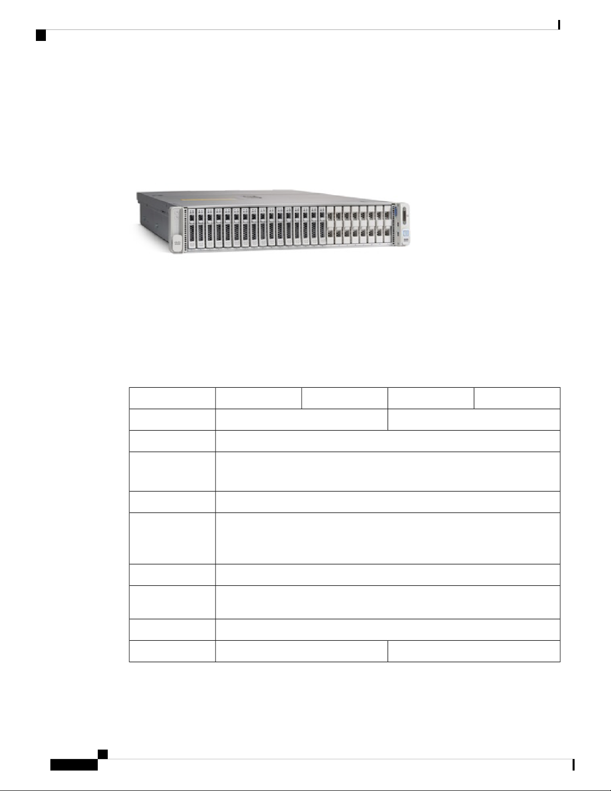
The Cisco Content Security Management Appliances (SMA) M195, M395, M695, and M695F centralize
reporting, tracking, management of quarantined email messages, and web security appliance configuration
settings. They also allow automated data backups.
The SMA M195, M395, M695, and M695F support Cisco AsyncOS version 12.5 and later. See Product ID
Numbers, on page 17 for a list of field-replaceable product IDs (PIDs) associated with the SMA security
management appliances.
The following figures show the Cisco Content Security Appliances.
Figure 1: Cisco Content Security M195 and M395
Cisco Content Security Management Appliance M195, M395, M695, and M695F Hardware Installation Guide
1
Page 6
Features
Overview
Figure 2: Cisco Content Security M695 and M695F
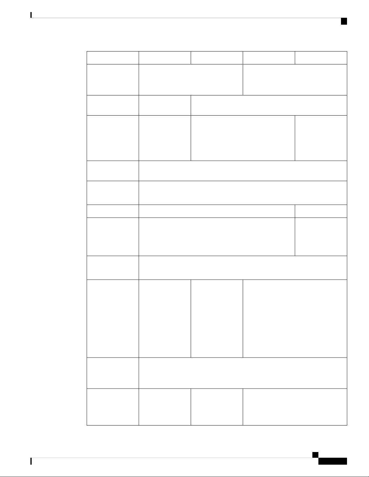
The following table lists the features of the SMA M195, M395, M695, and M695F.
Table 1: SMA M195, M395, M695, and M695F Features
2 RU1 RUForm factor
Standard 19-in. (48.3 cm) 4-post EIA rackRack mount
Airflow
Front to rear
Cold aisle to hot aisle
Displays the serial numberPullout asset card
Grounding holes
Two threaded holes for dual-hole grounding lug
Use is optional; the supported AC power supplies have internal grounding, so no
additional chassis grounding is required.
OptionalLocking faceplate
YesUnit identification
button
YesPower button
M695FM695M395M195Feature
16-GB RAMMemory
Cisco Content Security Management Appliance M195, M395, M695, and M695F Hardware Installation Guide
2
32-GB RAM
Page 7
Overview
Features
M695FM695M395M195Feature
RDIMMs
Management port
Network ports
cycling (RPC)
USB ports
One 16-GB
Internal component only; not
field-replaceable
One built-in port (MGMT)One built-in port
(DATA 1)
One Gigabit
Ethernet (DATA 2)
Five Gigabit Ethernet (DATA 1, DATA
2, DATA 3, DATA 4, DATA 5)
Accessed through the 1-Gb dedicated portRemote power
Two
USB 3.0 Type A
NoSFP+ ports
—Supported SFP+
Two 16-GB
Internal component only; not
field-replaceable
One Gigabit
Ethernet (DATA 1)
Two fiber optic
(DATA 2 and
DATA 3)
Two fiber optic
GLC-SX-MMD (1
Gb) (optional)
SFP-10G-SR (10
Gb) (optional)
Serial console port
AC power supply
Note
Do not
mix
power
supply
type or
wattage
between
models.
Fans
Storage
One 1-Gb RJ-45 serial port running RS-232 (RS-232D TIA-561)
Directly connects a computer to the chassis
One
770-W AC
You can order a
second power
Two
770-W AC
Hot-swappable and
redundant as 1+1
Two
1050-W AC
Hot-swappable and redundant as 1+1
supply for
redundancy as 1+1.
Six fans for front-to-rear cooling
Internal component only; not field-replaceable. If one fan fails, you must send your
chassis for RMA.
Two 600-GB SAS
HDDs
RAID 1,
hot-swappable
Eight 600-GB SAS
HDDs
RAID 10,
hot-swappable
Sixteen 600-GB SAS HDDs
RAID 10, hot-swappable
Cisco Content Security Management Appliance M195, M395, M695, and M695F Hardware Installation Guide
3
Page 8
Package Contents
Package Contents
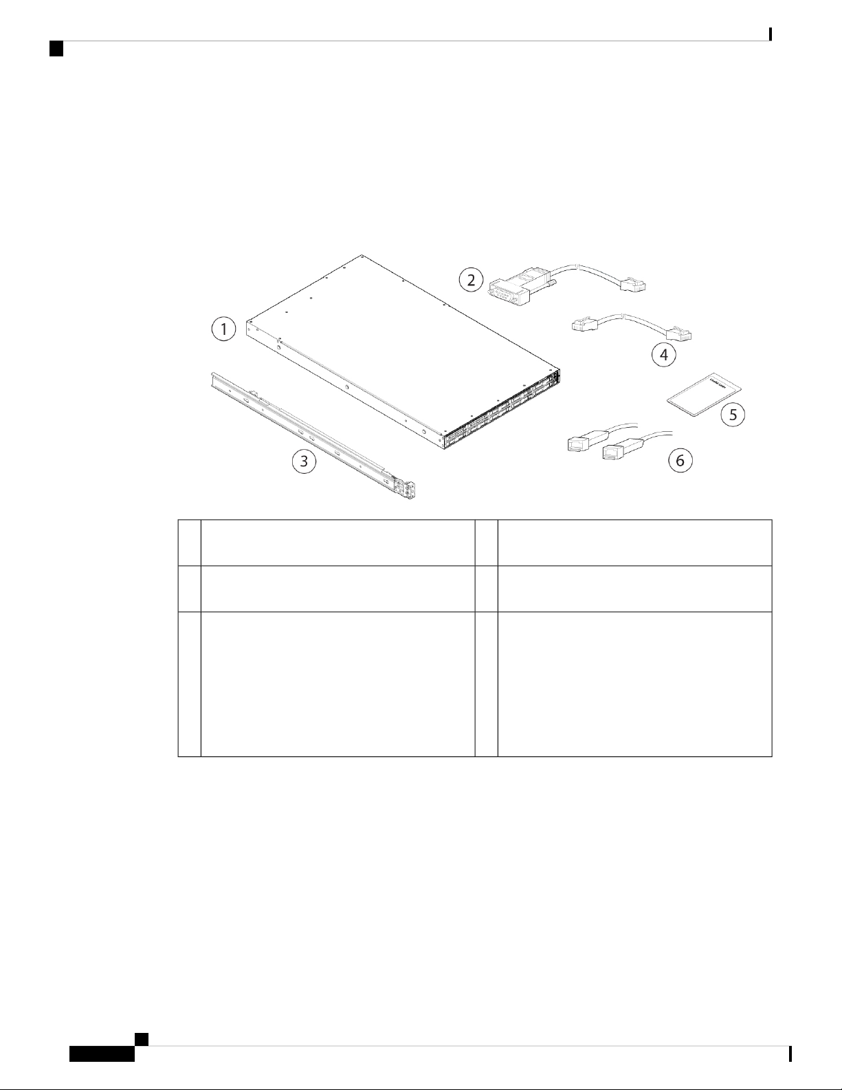
The following figure shows the package contents for the SMA M195, M395, M695, and M695F. Note that
the contents are subject to change and your exact contents might contain additional or fewer items.
Figure 3: Package Contents
Overview
5
The steps in the Useful Links document send you
to the documentation you need to install, set up,
and configure your SMA appliance.
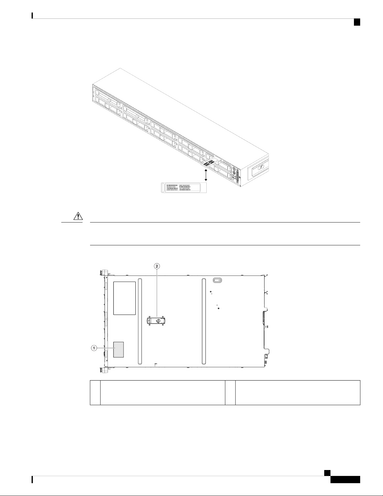
Serial Number Locations
The serial number (SN) for the SMA M195, M395, M695, and M695F is printed on the pullout asset card
located on the front panel as shown in the following figure.
RJ-45 to DB9-RS232 console cable (Cisco part
2Chassis1
number 72-3383-XX)
RJ-45 to RJ-45 Cat 5 Ethernet cable, yellow six
4Cisco rail kit (Cisco part number 800-43376-02)3
feet long (Cisco part number 72-1482-XX)
Two 1-Gb or 10-Gb SFP+ fiber optic transceivers
6Useful Links document
with cables
Note
Supported on the M695F. You cannot
mix SFP transceiver types in the same
chassis. You can either have two 1-Gb
or two 10-Gb SFPs in the same
chassis.
Cisco Content Security Management Appliance M195, M395, M695, and M695F Hardware Installation Guide
4
Page 9
Overview
Serial Number Locations
Figure 4: Serial Number on Pullout Asset Card
Caution
The serial number is also on the label on the cover of the chassis as shown in the following figure.
The cover latch on the top of the chassis cover is not supported. There are no internal field-replaceable parts
in the SMA M195, M395, M695, and M695F.
Figure 5: Serial Number Location on Cover
Cover latch
2Serial number label1
Not supported
Cisco Content Security Management Appliance M195, M395, M695, and M695F Hardware Installation Guide
5
Page 10
Front Panel
Front Panel
Overview
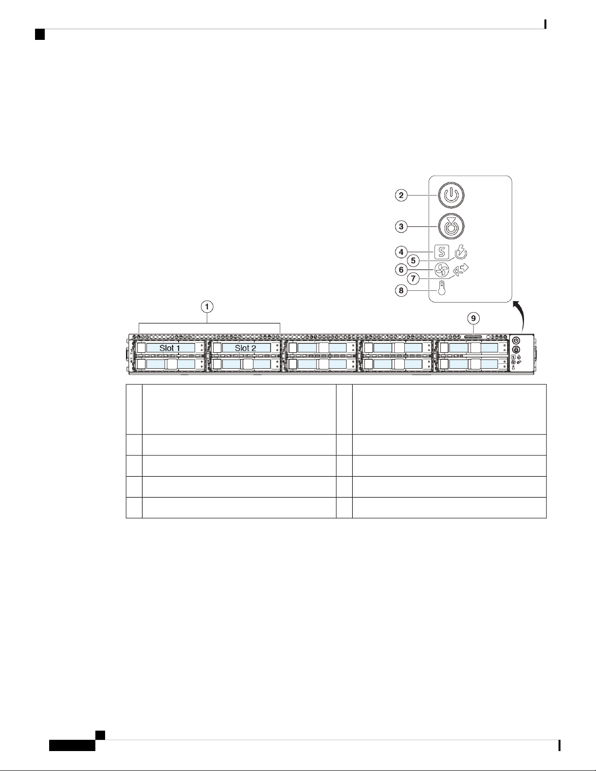
The following figure shows the front panel features and disk-drive configuration for the SMA M195. See
Front Panel LEDs, on page 8 for a description of the LEDs.
Figure 6: M195 Front Panel
1
Supports two 600-GB SAS HDDs in slots 1 and
2
Pullout asset card9
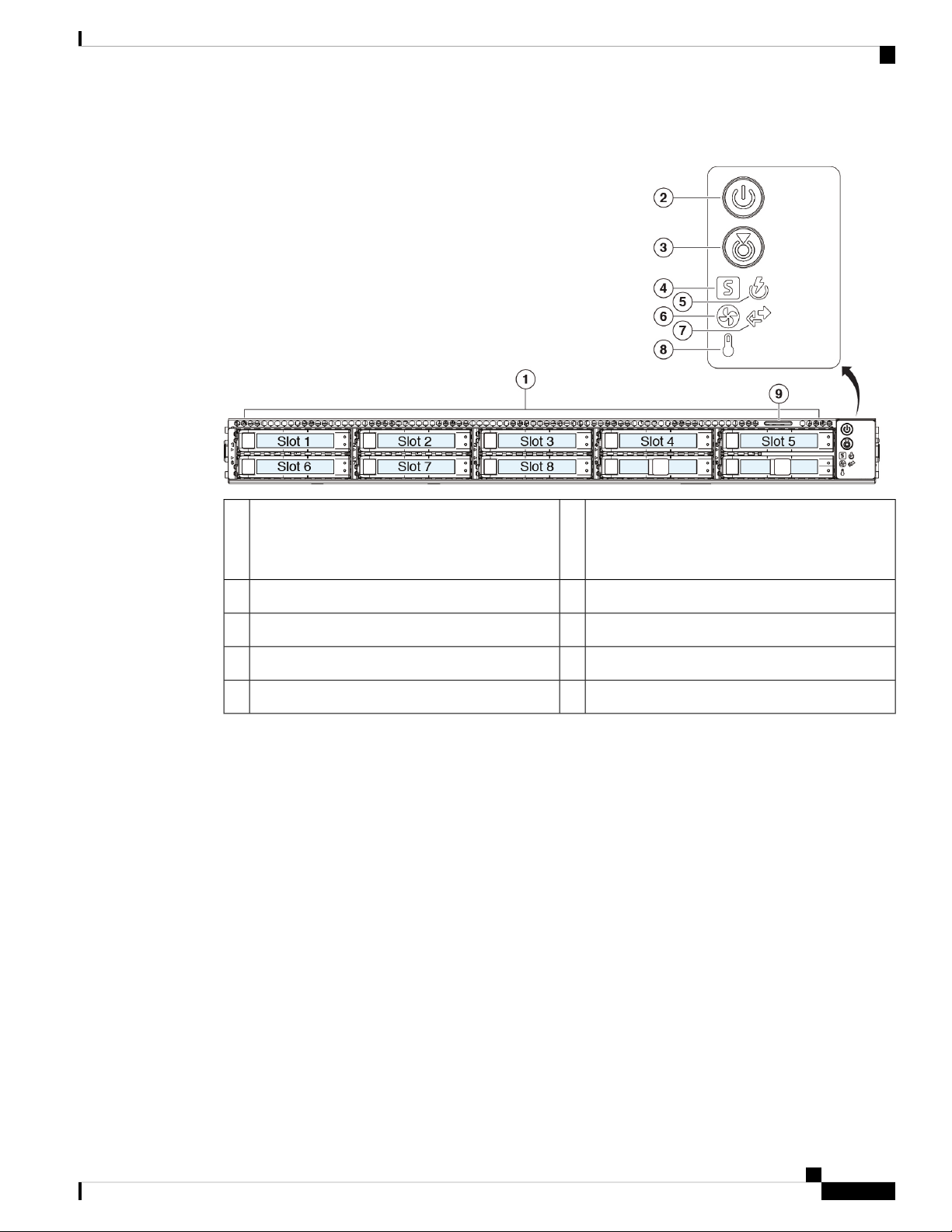
The following figure shows the front panel features and disk-drive configuration for the SMA M395. See
Front Panel LEDs, on page 8 for a description of the LEDs.
Power button/power status LED2Drive bays
System status LED4Unit identification button/LED3
Fan status LED6Power supply status LED5
Temperature status LED8Network link activity LED7
Cisco Content Security Management Appliance M195, M395, M695, and M695F Hardware Installation Guide
6
Page 11
Overview
Front Panel
Figure 7: M395 Front Panel
1
Power button/power status LED2Drive bays
Supports eight 600-GB SAS HDDs in slots 1
through 8
System status LED4Unit identification button/LED3
Fan status LED6Power supply status LED5
Temperature status LED8Network link activity LED7
Pullout asset card9
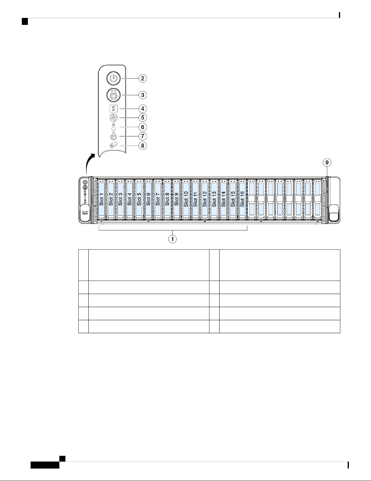
The following figure shows the front panel features and disk-drive configuration for the SMA M695 and
M695F. See Front Panel LEDs, on page 8 for a description of the LEDs.
Cisco Content Security Management Appliance M195, M395, M695, and M695F Hardware Installation Guide
7
Page 12
Front Panel LEDs
Overview
Figure 8: M695 and M695F Front Panel
1
Supports sixteen 600-GB SAS HDDs in slots 1
through 16
Pullout asset card9
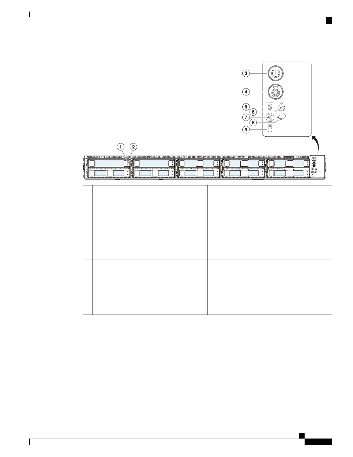
Front Panel LEDs
The following figure shows the front panel LEDs for the M195, M395, M695, and M695F, and describes
their states.
Power button/power status LED2Drive bays
System status LED4Unit identification button/LED3
Temperature status LED6Fan status LED5
Network link activity LED8Power supply status LED7
Cisco Content Security Management Appliance M195, M395, M695, and M695F Hardware Installation Guide
8
Page 13
Overview
Front Panel LEDs
Figure 9: Front Panel LEDs and Their States
Drive activity LED:
1
• Off—The drive is operating properly.
• Amber—Drive fault detected.
• Amber, flashing—The drive is rebuilding.
• Amber, flashing with 1-second
interval—Drive locate function activated in
2Drive fault LED:
• Off—There is no drive in the drive tray (no
access, no fault).
• Green—The drive is ready.
• Green, flashing—The drive is reading or
writing data.
the software.
Unit identification LED:
3
• Off—There is no AC power to the chassis.
• Amber—The chassis is in standby mode.
• Green—The chassis is in main power mode.
Power is supplied to all components.
4Power LED:
• Off—The unit identification function is not
in use.
• Blue, flashing—The unit identification
function is activated.
Cisco Content Security Management Appliance M195, M395, M695, and M695F Hardware Installation Guide
9
Page 14

Front Panel LEDs
Overview
Power supply status LED:
5
6System status LED:
• Green—The chassis is running in normal
operating condition.
• Green, flashing—The chassis is performing
system initialization and memory check.
• Amber—The chassis is in a degraded
operational state (minor fault).
• Power supply redundancy is lost.
• CPUs are mismatched.
• At least one CPU is faulty.
• At least one DIMM is faulty.
• At least one drive in a RAID
configuration failed.
• Amber, 2 flashes—There is a major fault
with the system board.
• Amber, 3 flashes—There is a major fault
with the DIMMs.
• Amber, 4 flashes—There is a major fault
with the CPUs.
• Green—All power supplies are operating
normally.
• Amber—One or more power supplies are in
a degraded operational state.
• Amber, flashing—One or more power
supplies are in a critical fault state.
7
• Green—All fans are operating properly.
• Amber, flashing—One or more fans
breached the nonrecoverable threshold.
Temperature status LED:
9
• Green—The chassis is operating at normal
temperature.
• Amber—One or more temperature sensors
breached the critical threshold.
• Amber, flashing—One or more temperature
sensors breached the nonrecoverable
threshold.
Network link activity LED:
8Fan status LED:
• Off—The Ethernet port link is idle.
• Green—One or more Ethernet ports are
link-active, but there is no activity.
• Green, flashing—One or more Ethernet ports
are link-active with activity.
Cisco Content Security Management Appliance M195, M395, M695, and M695F Hardware Installation Guide
10
Page 15
Overview
Rear Panel
Rear Panel
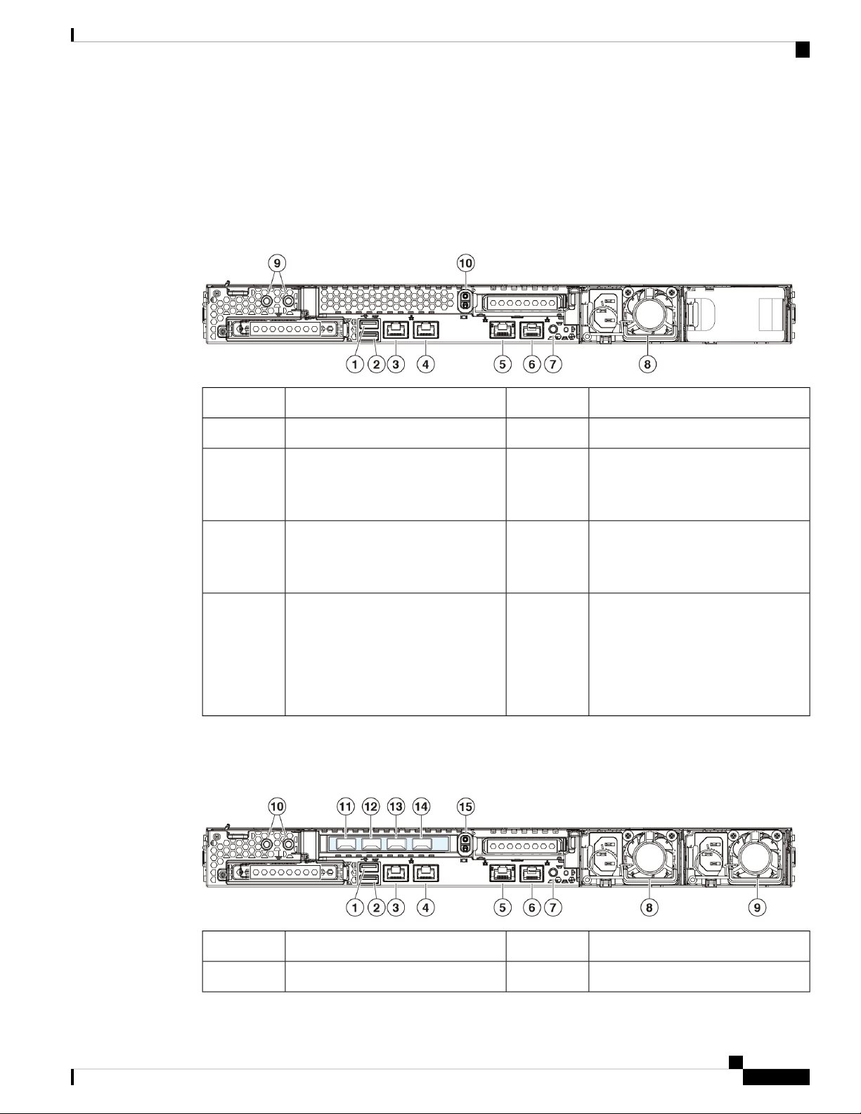
The following figure shows the rear panel of the SMA M195. See Rear Panel LEDs, on page 14 for a
description of the LEDs.
Figure 10: M195 Rear Panel
USB 3.0 Type A (USB 2)2USB 3.0 Type A (USB 1)1
Data interface (DATA 2)4Management interface (DATA 1)3
6RPC port (RPC)5
Serial console port (Console)
RJ-45 connector that directly connects
a computer to the appliance.
8Unit identification button7
One 770-W AC power supply
You can order a second power supply
to provide redundancy as 1 + 1.
9
10Threaded holes for dual-hole
grounding lug
Riser handle
Not supported
Use is optional; the supported AC
power supplies have internal
grounding, so no additional chassis
grounding is required.
The following figure shows the rear panel of the SMA M395. See Rear Panel LEDs, on page 14 for a
description of the LEDs.
Figure 11: M395 Rear Panel
USB 3.0 Type A (USB 2)2USB 3.0 Type A (USB 1)1
Data interface (DATA 5)4Management interface (MGMT)3
Cisco Content Security Management Appliance M195, M395, M695, and M695F Hardware Installation Guide
11
Page 16

Rear Panel
Overview
6RPC port (RPC)5
Serial console port (Console)
RJ-45 connector that directly connects
a computer to the appliance.
770-W AC power supply (PSU 1)8Unit identification button7
10770-W AC power supply (PSU 2)9
Threaded holes for dual-hole
grounding lug
Use is optional; the supported AC
power supplies have internal
grounding, so no additional chassis
grounding is required.
Data interface (DATA 2)12Data interface (DATA 1)11
Data interface (DATA 4)14Data interface (DATA 3)13
15
Riser handle
Not supported
The following figure shows the rear panel of the SMA M695. See Rear Panel LEDs, on page 14 for a
description of the LEDs.
Figure 12: M695 Rear Panel
Data interface (DATA 2)2Data interface (DATA 1)1
Data interface (DATA 4)4Data interface (DATA 3)3
1050-W AC power supply (PSU 2)61050-W AC power supply (PSU1)5
7
USB 3.0 Type A (USB 1)8Threaded holes for dual-hole
grounding lug
Use is optional; the supported AC
power supplies have internal
grounding, so no additional chassis
grounding is required.
Management interface (MGMT)10USB 3.0 Type A (USB 2)9
Cisco Content Security Management Appliance M195, M395, M695, and M695F Hardware Installation Guide
12
Page 17

Overview
Rear Panel
RPC port (RPC)12Data interface (DATA 5)11
13
Unit identification button14Serial console port (Console)
RJ-45 connector that directly connects
a computer to the appliance.
The following figure shows the rear panel of the SMA M695F. See Rear Panel LEDs, on page 14 for a
description of the LEDs.
Figure 13: M695F Rear Panel
1
2Data interface (DATA 2)
1/10-Gigabit SFP+ fiber optic support
Use only Cisco-supported SFP+
transceivers.
Data interface (DATA 3)
1/10-Gigabit SFP+ fiber optic support
Use only Cisco-supported SFP+
transceivers.
5
11
1050-W AC power supply (PSU 2)41050-W AC power supply (PSU 1)3
USB 3.0 Type A (USB 1)6Threaded holes for dual-hole
grounding lug
Use is optional; the supported AC
power supplies have internal
grounding, so no additional chassis
grounding is required.
Management interface (MGMT)8USB 3.0 Type A (USB 2)7
RPC port (RPC)10Data interface (DATA 1)9
Unit identification button12Serial console port (Console)
RJ-45 connector that directly connects
a computer to the appliance.
Cisco Content Security Management Appliance M195, M395, M695, and M695F Hardware Installation Guide
13
Page 18

Rear Panel LEDs
Rear Panel LEDs
The following figure shows the rear panel LEDs of the SMA M195 model and describes the LED states. The
M395, M695, and M695F have the same LEDs except that these models have more data interfaces; the speed
and status LED descriptions are the same.
Figure 14: Rear Panel LEDs and Their States
Overview
1
• Off—Link speed is 100 Mbps.
• Amber—Link speed is 1 Gbps.
• Green—Link speed is 10 Gbps.
3
• Off—Link speed is 10 Mbps.
• Amber—Link speed is 100 Mbps.
• Green—Link speed is 1 Gbps.
2Management interface link speed:
4Data interface link speed:
Management interface link status:
• Off—No link is present.
• Green—Link is active.
• Green, flashing—Traffic is
present on the active link.
Data interface link status:
• Off—No link is present.
• Green—Link is active.
• Green, flashing—Traffic is
present on the active link.
Cisco Content Security Management Appliance M195, M395, M695, and M695F Hardware Installation Guide
14
Page 19

Overview
Power Supply
5
• Off—The unit identification
function is not in use.
• Blue, flashing—The unit
identification function is
activated.
6Rear unit identification:
Power supply (one LED for each
power supply):
• Off—No AC input (12-V main
power off; 12-V standby power
off)
• Green, flashing—12-V main
power off; 12-V standby power
on.
• Green—12-V main power on;
12-V standby power on.
• Amber, flashing—Warning
threshold detected but 12-V main
power on.
• Amber—Critical error detected;
12-V main power off ( for
example, overcurrent,
overvoltage, or overtemperature
failure).
Power Supply
The following table lists the specifications for the 770-W AC power supply (Cisco part number 341-0591-04)
used in the SMA M195 and M395.
Table 2: 770-W Power Supply Specifications
AC input voltage range
AC input frequency
Maximum AC input current
SpecificationDescription
Nominal range: 100 to 120 V AC, 200 to 240 V AC
Range: 90–132 V AC, 180–264 V AC
Nominal range: 50–60 Hz
Range: 47–63 Hz
9.5 A peak at 100-V AC
4.5 A peak at 208 V AC
950 VA at 100 V ACMaximum input volt amperes
770 WMaximum output power for each power supply
15 A (subcycle duration)Maximum inrush current
12 ms at 770 WMaximum hold-up time
12 V DCPower supply output voltage
Cisco Content Security Management Appliance M195, M395, M695, and M695F Hardware Installation Guide
15
Page 20

Hardware Specifications
Overview
SpecificationDescription
12 V DCPower supply standby voltage
Efficiency rating
The following table lists the specifications for the 1050-W AC power supply (Cisco part number 341-0638-03)
used in the SMA M695 and 695F.
Table 3: 1050-W Power Supply Specifications
AC input voltage range
AC input frequency
Maximum AC input current
Climate Savers Platinum Efficiency (80 Plus Platinum
certified)
RSP2Form factor
IEC320 C13/C15Input connector
SpecificationDescription
Nominal range: 100 to 120 V AC, 200 to 240 V AC
Range: 90–132 V AC, 180–264 V AC
Nominal range: 50–60 Hz
Range: 47–63 Hz
12.5 A peak at 100 V AC
6.0 A peak at 208 V AC
1250 VA at 100 V ACMaximum input volt amperes
Efficiency rating
Hardware Specifications
The following table lists the hardware specifications for the SMA M195, M395, M695, and M695F.
1050 WMaximum output power for each power supply
15 A (subcycle duration)Maximum inrush current
12 ms at 1050 WMaximum hold-up time
12 V DCPower supply output voltage
12 V DCPower supply standby voltage
Climate Savers Platinum Efficiency (80 Plus Platinum
certified)
RSP2Form factor
IEC320 C14Input connector
Cisco Content Security Management Appliance M195, M395, M695, and M695F Hardware Installation Guide
16
Page 21

Overview
Product ID Numbers
Table 4: M195, M395, M695, and M695F Hardware Specifications
M695FM695M395M195Specification
Dimensions (H x W
x D)
Temperature
Relative humidity
Altitude
Sound power level
Sound pressure level
1.7 x 16.89 x 29.8 in. (4.32 x 43.0 x 75.6
cm)
35.3 lbs (16.01 kg)30.5 lbs (13.84 kg)Weight
3.4 x 16.9 x 29.5 in. (8.64 x 42.92 x 74.93
cm)
51.4 lbs (23.31 kg)51.2 lbs (23.22 kg)
Operating: 41 to 95°F (5 to 35°C)
Derate the maximum temperature by 1°C for every 1000 ft (305 m) of altitude above
sea level.
Nonoperating: –40 to 149°F (–40 to 65°C)
When stored or transported
Operating: 10 to 90% noncondensing
Nonoperating: 5 to 93% noncondensing
Operating: 0 to 10,000 ft
Nonoperating: 0 to 40,000 ft
When stored or transported
5.5 Bels (measure A-weighted per ISO7779 LWAd)
Operation at 73°F (23°C)
40 dBa (measure A-weighted per ISO7779 LpAM)
Product ID Numbers
The following table lists the field-replaceable PIDs associated with SMA M195, M395, M695, and M695F.
The spare components are ones that you can order and replace yourself. If any internal components fail, you
must RMA the entire chassis including the SFPs and SFP cables. Remove the drives and power supplies before
you send the chassis for RMA.
Table 5: SMA C195, C395, C695, and C695F PIDs
Operation at 73°F (23°C)
DescriptionPID
SMA M195, M395, M695, M695F HDDCCS-HDD-600GB10K
SMA M195, M395, M695, M695F HDD (spare)CCS-HDD-600GB10K=
SMA M195 and M395 770 AC power supplyCCS-PSU1-770AC
SMA M195 and M395 770 AC power supply (spare)CCS-PSU1-770AC=
SMA M695 and M695F 1050 AC power supplyCCS-PSU1-1050AC
Cisco Content Security Management Appliance M195, M395, M695, and M695F Hardware Installation Guide
17
Page 22

Power Cord Specifications
Overview
DescriptionPID
CCS-PSU1-1050AC=
UCSC-BZL-C240M5=
Power Cord Specifications
SMA M695 and M695F 1050 AC power supply
(spare)
SMA M195, M395, M695, and M695F rail kitUCSC-RAILB-M4
SMA M195, M395, M695, and M695F rail kit (spare)UCSC-RAILB-M4=
SMA M195 and M395 1 RU locking faceplateUCSC-BZL-C220M5
SMA M195 and M395 1 RU locking faceplate (spare)UCSC-BZL-C220M5=
SMA M695 and M695F 2 RU locking faceplateUCSC-BZL-C240M5
SMA M695 and M695F 2 RU locking faceplate
(spare)
ESA C695F 10-Gb SFPSFP-10G-SR
ESA C695F 10-Gb SFP (spare)SFP-10G-SR=
ESA C695F 1-Gb SFPGLC-SX-MMD
ESA C695F 1-Gb SFP (spare)GLC-SX-MMD=
Each power supply has a separate power cord. Standard power cords or jumper power cords are available for
connection to the SMA. The jumper power cords for use in racks are available as an optional alternative to
the standard power cords.
If you do not order the optional power cord with the system, you are responsible for selecting the appropriate
power cord for the product. Using a incompatible power cord with this product may result in electrical safety
hazard. Orders delivered to Argentina, Brazil, and Japan must have the appropriate power cord ordered with
the system.
The following power cords and jumper cords are supported.
Figure 15: Argentina CAB-250V-10A-AR
Cord set rating: 10 A, 250 V2Plug: IRAM 20731
Cisco Content Security Management Appliance M195, M395, M695, and M695F Hardware Installation Guide
18
Page 23

Overview
Power Cord Specifications
Connector: IEC 60320/C133
Figure 16: Australia CAB-9K10A-AU
Cord set rating: 10 A, 250 V2Plug: A.S. 3112-20001
Connector: IEC 60320/C153
Figure 17: Brazil PWR-250V-10A-BZ
Connector: IEC 60320/C133
Figure 18: Cabinet Jumper CAB-C13-C14-2M
Connector: HS10S, C-13 to C-143
Cord set rating: 10 A, 250 V2Plug: NBR 141361
Cord set rating: 10A, 250V2Plug: SS10A1
Cisco Content Security Management Appliance M195, M395, M695, and M695F Hardware Installation Guide
19
Page 24

Power Cord Specifications
Figure 19: Cabinet Jumper CAB-C13-C14-AC
3
Figure 20: Cabinet Jumper CAB-C13-CBN
Overview
Cord set rating: 10 A, 250 V2Plug: SS10A1
Connector: HS10S, C-13 to C-14 (recessed
receptacle)
Connector: HS10S, C-13 to C-143
Figure 21: China CAB-250V-10A-CH
Connector: IEC 60320/C133
Cord set rating: 10 A, 250 V2Plug: SS10A1
Cord set rating: 10 A, 250 V2Plug: GB2099.1/20081
Cisco Content Security Management Appliance M195, M395, M695, and M695F Hardware Installation Guide
20
Page 25

Overview
Power Cord Specifications
Figure 22: Europe CAB-9K10A-EU
Cord set rating: 10 A/16 A, 250 V2Plug: CEE 7/7 (M2511)1
Connector: IEC 60320/C15 (VSCC 15)3
Figure 23: India CAB-250V-10A-ID
Connector: IEC 60320-C133
Figure 24: Israel CAB-250V-10A-IS
Connector: IEC 60320-C133
Cord set rating: 16 A, 250 V2Plug: IS 6538-19711
Cord set rating: 10 A, 250 V2Plug: SI-321
Cisco Content Security Management Appliance M195, M395, M695, and M695F Hardware Installation Guide
21
Page 26

Power Cord Specifications
Figure 25: Italy CAB-9K10A-IT
3
Figure 26: Japan CAB-JPN-3PIN
Overview
Cord set rating: 10 A, 250 V2Plug: CEI 23-16/VII (I/3G)1
Connector: IEC 60320/C15
(EN 60320/C15M)
Connector: IEC 60320/C133
Figure 27: Japan CAB-C13-C14-2M-JP
Connector: EN 60320/C13 to C143
Cord set rating: 12 A, 125 V2Plug: JIS 83031
Cord set rating: 10 A, 250 V2Plug: EN 60320-2-2/E1
Cisco Content Security Management Appliance M195, M395, M695, and M695F Hardware Installation Guide
22
Page 27

Overview
Power Cord Specifications
Figure 28: Korea CAB-9K10S-KOR
Cord set rating: 10 A, 250 V2Plug: EL211 (KSC 8305)1
Connector: IEC 60320/C153
Figure 29: North America CAB-9K12A-NA
Connector: IEC 60320/C153
Figure 30: North America CAB-N5K6A-NA
Connector: IEC 60320/C133
Cord set rating: 13 A, 125 V2Plug: NEMA5-15P1
Cord set rating: 10 A, 125 V2Plug: NEMA6-15P1
Cisco Content Security Management Appliance M195, M395, M695, and M695F Hardware Installation Guide
23
Page 28

Power Cord Specifications
Figure 31: North America CAB-AC-L620-C13
Figure 32: Switzerland CAB-9K10A-SW
Overview
Cord set rating: 13 A, 250 V2Plug: NEMA L6-20 (molded twist lock)1
Connector: IEC 60320/C133
Connector: IEC 60320/C153
Figure 33: Taiwan CAB-ACTW
Connector: IEC 60320/C133
Cord set rating: 10 A, 250 V2Plug: SEV 1011 (MP232-R)1
Cord set rating: 10 A, 125 V2Plug: EL 302 (CNS10917)1
Cisco Content Security Management Appliance M195, M395, M695, and M695F Hardware Installation Guide
24
Page 29

Overview
Power Cord Specifications
Figure 34: United Kingdom CAB-9K10A-UK
Cord set rating: 10 A, 250 V2Plug: BS1363A/SS1451
Connector: IEC 60320/C153
Cisco Content Security Management Appliance M195, M395, M695, and M695F Hardware Installation Guide
25
Page 30

Power Cord Specifications
Overview
Cisco Content Security Management Appliance M195, M395, M695, and M695F Hardware Installation Guide
26
Page 31

Installation Preparation
• Installation Warnings, on page 27
• Safety Recommendations, on page 28
• Maintain Safety with Electricity, on page 29
• Prevent ESD Damage, on page 29
• Site Environment, on page 30
• Site Considerations, on page 30
• Power Supply Considerations, on page 30
• Rack Configuration Considerations, on page 31
Installation Warnings
Read the Regulatory Compliance and Safety Information document before installing the chassis.
Take note of the following warnings:
CHAPTER 2
Warning
Note
Statement 1071—Warning Definition
IMPORTANT SAFETY INSTRUCTIONS
This warning symbol means danger. You are in a situation that could cause bodily injury. Before you work
on any equipment, be aware of the hazards involved with electrical circuitry and be familiar with standard
practices for preventing accidents. Use the statement number provided at the end of each warning to locate
its translation in the translated safety warnings that accompanied this device.
SAVE THESE INSTRUCTIONS
Statement 1005—Circuit Breaker
This product relies on the building's installtion for short-circuit (overcurrent) protection. Ensure that the
protective device is rated not great than: 250 V, 15 A.
Cisco Content Security Management Appliance M195, M395, M695, and M695F Hardware Installation Guide
27
Page 32

Safety Recommendations
Installation Preparation
Warning
Warning
Warning
Statement 1006—Chassis Warning for Rack-Mounting and Servicing
To prevent bodily injury when mounting or servicing this unit in a rack, you must take special precautions to
ensure that the system remains stable. The following guidelines are provided to ensure your safety:
• This unit should be mounted at the bottom of the rack if it is the only unit in the rack.
• When mounting this unit in a partially filled rack, load the rack from the bottom to the top with the
heaviest component at the bottom of the rack.
• If the rack is provided with stabilizing devices, install the stabilizers before mounting or servicing the
unit in the rack.
Statement 1017—Restricted Area
This unit is intended for installation in restricted access areas. A restricted access area can be accessed by
skilled, instructed or qualified personnel.
Statement 1019—Main Disconnecting Device
The plug-socket combination must be accessible at all times, because it serves as the main disconnecting
device.
Note
Statement 1047—Overheating Prevention
To prevent the system from overheating, do not operate it in an area that exceeds the maximum recommended
ambient temperature of: 95° F (35° C).
Warning
Statement 1074—Comply with Local and National Electrical Codes
To reduce risk of electric shock or fire, installation of the equipment must comply with local and national
electrical codes.
Safety Recommendations
Observe these safety guidelines:
• Keep the area clear and dust free before, during, and after installation.
• Keep tools away from walkways, where you and others might trip over them.
• Do not wear loose clothing or jewelry, such as earrings, bracelets, or chains that could get caught in the
chassis.
Cisco Content Security Management Appliance M195, M395, M695, and M695F Hardware Installation Guide
28
Page 33

Installation Preparation
• Wear safety glasses if you are working under any conditions that might be hazardous to your eyes.
• Do not perform any action that creates a potential hazard to people or makes the equipment unsafe.
• Never attempt to lift an object that is too heavy for one person.
Maintain Safety with Electricity
Maintain Safety with Electricity
Warning
Before working on a chassis, be sure the power cord is unplugged.
Read the Regulatory Compliance and Safety Information document before installing the chassis.
Follow these guidelines when working on equipment powered by electricity:
• Before beginning procedures that require access to the interior of the chassis, locate the emergency
power-off switch for the room in which you are working. Then, if an electrical accident occurs, you can
act quickly to turn off the power.
• Do not work alone if potentially hazardous conditions exist anywhere in your work space.
• Never assume that power is disconnected; always check.
• Look carefully for possible hazards in your work area, such as moist floors, ungrounded power extension
cables, frayed power cords, and missing safety grounds.
• If an electrical accident occurs:
• Use caution; do not become a victim yourself.
• Disconnect power from the chassis.
• If possible, send another person to get medical aid. Otherwise, assess the condition of the victim,
and then call for help.
• Determine whether the person needs rescue breathing or external cardiac compressions; then take
appropriate action.
• Use the chassis within its marked electrical ratings and product usage instructions.
• The Cisco Content Security Appliance x95 Series are equipped with an AC-input power supply, which
is shipped with a three-wire electrical cord with a grounding-type plug that fits into a grounding-type
power outlet only. Do not circumvent this safety feature. Equipment grounding should comply with local
and national electrical codes.
Prevent ESD Damage
ESD occurs when electronic components are improperly handled, and it can damage equipment and impair
electrical circuitry, which can result in intermittent or complete failure of your equipment.
Always follow ESD-prevention procedures when removing and replacing components. Ensure that the chassis
is electrically connected to an earth ground. Wear an ESD-preventive wrist strap, ensuring that it makes good
Cisco Content Security Management Appliance M195, M395, M695, and M695F Hardware Installation Guide
29
Page 34

Site Environment
skin contact. Connect the grounding clip to an unpainted surface of the chassis frame to safely ground ESD
voltages. To properly guard against ESD damage and shocks, the wrist strap and cord must operate effectively.
If no wrist strap is available, ground yourself by touching the metal part of the chassis.
For safety, periodically check the resistance value of the antistatic strap, which should be between one and
10 megohms.
Site Environment
See Hardware Specifications, on page 16 for information about physical specifications.
When planning the site layout and equipment locations, consider the information in the next section to help
avoid equipment failures and reduce the possibility of environmentally caused shutdowns. If you are currently
experiencing shutdowns or unusually high error rates with your existing equipment, these considerations may
help you isolate the cause of failures and prevent future problems.
Site Considerations
Installation Preparation
Considering the following helps you plan an acceptable operating environment for the chassis, and avoid
environmentally-caused equipment failures.
• Electrical equipment generates heat. Ambient air temperature might not be adequate to cool equipment
to acceptable operating temperatures without adequate circulation. Make sure that the room in which
you operate your system has adequate air circulation.
• Ensure that the chassis cover is secure. The chassis is designed to allow cooling air to flow effectively
within it. An open chassis allows air leaks, which may interrupt and redirect the flow of cooling air from
the internal components.
• Always follow ESD-prevention procedures to avoid damage to equipment. Damage from static discharge
can cause immediate or intermittent equipment failure.
Power Supply Considerations
See Power Supply, on page 15 for more detailed information about the power supply in the chassis.
When installing the chassis, consider the following:
• Check the power at the site before installing the chassis to ensure that it is free of spikes and noise. Install
a power conditioner, if necessary, to ensure proper voltages and power levels in the appliance-input
voltage.
• Install proper grounding for the site to avoid damage from lightning and power surges.
• The chassis does not have a user-selectable operating range. Refer to the label on the chassis for the
correct appliance input-power requirement.
• Several styles of AC-input power supply cords are available for the chassis; make sure that you have the
correct style for your site.
Cisco Content Security Management Appliance M195, M395, M695, and M695F Hardware Installation Guide
30
Page 35

Installation Preparation
• If you are using dual redundant (1+1) power supplies, we recommend that you use independent electrical
circuits for each power supply.
• Install an uninterruptible power source for your site, if possible.
Rack Configuration Considerations
See Rack-Mount the Chassis, on page 33 for the rack-mount procedure.
Consider the following when planning a rack configuration:
• If you are mounting a chassis in an open rack, make sure that the rack frame does not block the intake
or exhaust ports.
• Be sure enclosed racks have adequate ventilation. Make sure that the rack is not overly congested as each
chassis generates heat. An enclosed rack should have louvered sides and a fan to provide cooling air.
• In an enclosed rack with a ventilation fan in the top, heat generated by equipment near the bottom of the
rack can be drawn upward and into the intake ports of the equipment above it in the rack. Ensure that
you provide adequate ventilation for equipment at the bottom of the rack.
Rack Configuration Considerations
• Baffles can help to isolate exhaust air from intake air, which also helps to draw cooling air through the
chassis. The best placement of the baffles depends on the airflow patterns in the rack. Experiment with
different arrangements to position the baffles effectively.
Cisco Content Security Management Appliance M195, M395, M695, and M695F Hardware Installation Guide
31
Page 36

Rack Configuration Considerations
Installation Preparation
Cisco Content Security Management Appliance M195, M395, M695, and M695F Hardware Installation Guide
32
Page 37

CHAPTER 3
Rack-Mount the Chassis
• Unpack and Inspect the Chassis, on page 33
• Rack-Mount the Chassis, on page 33
Unpack and Inspect the Chassis
Note
The chassis is thoroughly inspected before shipment. If any damage occurred during transportation or any
items are missing, contact your customer service representative immediately. Keep the shipping container in
case you need to send the chassis back due to damage.
See Package Contents, on page 4 for a list of what shipped with the chassis.
Step 1 Remove the chassis from its cardboard container and save all packaging material.
Step 2 Compare the shipment to the equipment list provided by your customer service representative. Verify that you have all
items.
Step 3 Check for damage and report any discrepancies or damage to your customer service representative. Have the following
information ready:
• Invoice number of shipper (see the packing slip)
• Model and serial number of the damaged unit
• Description of damage
• Effect of damage on the installation
Rack-Mount the Chassis
You can install the chassis in a rack using the Cisco rack kit (part number 800-43376-02).
The rack must be of the following type:
Cisco Content Security Management Appliance M195, M395, M695, and M695F Hardware Installation Guide
33
Page 38

Rack-Mount the Chassis
Note
Rack-Mount the Chassis
• A standard 19-in. (48.3-cm) wide, 4-post EIA rack with mounting posts that conform to English universal
hole spacing per section 1 of ANSI/EIA-310-D-1992.
• The rack post holes can be square 0.38-in. (9.6 mm), round 0.28-in. (7.1 mm), #12-24 UNC, or #10-32
UNC when you use the supplied slide rails.
• The minimum vertical rack space per appliance must be 1 RU, equal to 1.75 in. (44.45 mm).
• The slide rails for the chassis have an adjustment range of 24 to 36 in. (610 to 914 mm).
The slide rails that ship with the chassis do not require tools for installation if you install them in a rack that
has square 0.38-in. (9.6 mm), round 0.28-in. (7.1 mm), or #12-24 UNC threaded holes.
Before you begin
Take note of the following warning:
Warning
Statement 1006—Chassis Warning for Rack-Mounting and Servicing
To prevent bodily injury when mounting or servicing this unit in a rack, you must take special precautions to
ensure that the system remains stable. The following guidelines are provided to ensure your safety:
• This unit should be mounted at the bottom of the rack if it is the only unit in the rack.
• When mounting this unit in a partially filled rack, load the rack from the bottom to the top with the
heaviest component at the bottom of the rack.
• If the rack is provided with stabilizing devices, install the stabilizers before mounting or servicing the
unit in the rack.
Step 1 Attach the inner rails to the sides of the chassis:
a) Align an inner rail with one side of the chassis so that the three keyed slots in the rail align with the three pegs on the
side of the chassis.
b) Set the keyed slots over the pegs, and then slide the rail toward the front to lock it in place on the pegs. The front slot
has a metal clip that locks over the front peg.
c) Install the second inner rail to the opposite side of the chassis.
Figure 35: Attach the Inner Rail to Side of Server
Locking clip on inner rail2Front of chassis1
Cisco Content Security Management Appliance M195, M395, M695, and M695F Hardware Installation Guide
34
Page 39

Rack-Mount the Chassis
Rack-Mount the Chassis
Step 2 Open the front securing plate on both slide-rail assemblies. The front end of the slide-rail assembly has a spring-loaded
securing plate that must be open before you can insert the mounting pegs into the rack-post holes.
On the outside of the assembly, push the green arrow button toward the rear to open the securing plate.
Figure 36: Front Securing Mechanism, Inside of Front End
Securing plate shown pulled back to open position3
Step 3 Install the slide rails into the rack:
a) Align one slide-rail assembly front end with the front rack-post holes that you want to use.
The slide rail front end wraps around the outside of the rack post and the mounting pegs enter the rack-post holes
from the outside-front.
Note
The rack post must be between the mounting pegs and the open securing plate.
b) Push the mounting pegs into the rack-post holes from the outside-front.
c) Press the securing plate release button, marked “PUSH.” The spring-loaded securing plate closes to lock the pegs in
place.
d) Attach the second slide-rail assembly to the opposite side of the rack. Make sure that the two slide-rail assemblies
are at the same height with each other and are level front-to-back.
e) Pull the inner slide rails on each assembly out toward the rack front until they hit the internal stops and lock in place.
Step 4 Insert the chassis into the slide rails:
a) Align the rear of the inner rails that are attached to the chassis sides with the front ends of the empty slide rails on
the rack.
b) Push the inner rails into the slide rails on the rack until they stop at the internal stops.
c) Slide the release clip toward the rear on both inner rails, and then continue pushing the chassis into the rack until its
front slam latches engage with the rack posts
Rack post2Front mounting pegs1
Cisco Content Security Management Appliance M195, M395, M695, and M695F Hardware Installation Guide
35
Page 40

Rack-Mount the Chassis
Rack-Mount the Chassis
Figure 37: Inner Rail Release Clip
Inner rail attached to chassis and inserted into outer
2Inner rail release clip1
rail
Outer rail attached to rack post3
Step 5 (Optional) Secure the chassis in the rack more permanently by using the two screws that are provided with the slide rails.
Perform this step if you plan to move the rack with chassis installed. With the chassis fully pushed into the slide rails,
open a hinged slam latch lever on the front of the chassis and insert the screw through the hole that is under the lever.
The screw threads into the static part of the rail on the rack post and prevents the chassis from being pulled out. Repeat
for the opposite slam latch.
What to do next
Install the cables according to your default software configuration as described in the Getting Started Guide
for your software version.
Cisco Content Security Management Appliance M195, M395, M695, and M695F Hardware Installation Guide
36
Page 41

Maintenance and Upgrade
• Power Button Shut Down, on page 37
• Enable RPC, on page 38
• Reset the Chassis Remotely, on page 39
• Install/Uninstall the Locking Faceplate, on page 39
• Remove and Replace a Drive, on page 40
• Remove and Replace a Power Supply, on page 43
Power Button Shut Down
The chassis runs in two modes:
• Main power mode—Power is supplied to all components and all operating systems can run.
• Standby power mode—Power is supplied only to the service processor and certain components. You can
safely remove power cords from the chassis in this mode.
CHAPTER 4
Caution
Step 1 Check the Power LED:
• Amber—The chassis is already in standby mode and you can safely remove power.
• Green—The chassis is in main power mode and you must shut it down before you can safely remove power.
Step 2 Perform a graceful shutdown or a hard shutdown:
Caution
• Graceful shutdown—Press and release the Power button. The operating system performs a graceful shutdown and
After you shut down the chassis to standby power, electric current is still present in the chassis. To completely
remove power as directed in some maintenance procedures, you must disconnect all power cords from all
power supplies in the chassis.
You can shut down the chassis using the front panel Power button or software management.
To avoid data loss or damage to your operating system, perform a graceful shutdown of the operating system.
the chassis goes into standby mode. The power LED is amber.
Cisco Content Security Management Appliance M195, M395, M695, and M695F Hardware Installation Guide
37
Page 42

Maintenance and Upgrade
Enable RPC
• Emergency shutdown—Press and hold the Power button for four seconds to force the main power off and immediately
enter standby mode.
Step 3 If a maintenance procedure instructs you to completely remove power from the chassis, disconnect all power cords from
the power supplies.
Enable RPC
You must enable and configure RPC before you can remotely reset chassis power.
Before you begin
• Cable the RPC port directly to a secure network.
• Open necessary ports through the firewall to make sure the chassis is accessible remotely.
• RPC requires a unique IPv4 address for the RPC port. You must use the following procedure to configure
the RPC port. You cannot configure it using the ipconfig command.
• To cycle chassis power you must have a third-party tool that supports the Intelligent Platform Management
Interface (IPMI) version 2.0.
Step 1 Use SSH or the serial console port to access the CLI.
Step 2 Log in using an account with Administrator access.
Step 3 Enter the following commands:
remotepower
setup
Step 4 Follow the prompts to specify the following:
• The dedicated IP address for the RPC port, netmask, and gateway.
• The username and password required to execute the power-cycle command.
These credentials are independent of other credentials used to access your appliance. Store this information for
administrators who may need to set up RPC in the future.
Step 5 Enter commit to save your changes.
Step 6 Test your configuration to verify that you can remotely manage chassis power.
What to do next
Reset the Chassis Remotely
Cisco Content Security Management Appliance M195, M395, M695, and M695F Hardware Installation Guide
38
Page 43

Maintenance and Upgrade
Reset the Chassis Remotely
Reset the Chassis Remotely
If the chassis requires a hard reset, you can reboot the chassis remotely using a third-party IPMI tool.
Before you begin
• You must enable RPC in advance. See Enable RPC, on page 38 for the procedure.
• Only the following IPMI commands are supported. Refer to your IPMI tool documentation on how to
use them.
status, on, off, cycle, reset, diag, soft
• Set up a utility that can manage devices using IPMI version 2.0.
Step 1 Use IPMI to issue a supported power-cycling command to the IP address assign to the RPC port.
Note
For example, issue the following command from a UNIX computer with IPMI support:
ipmitool -I lan -H ip-address -U remoteresetuser -P password chassis power reset
Step 2 Wait at least 11 minutes for the chassis to reboot.
The RPC port must be configured with the required credentials. See Enable RPC, on page 38 for more
information.
Install/Uninstall the Locking Faceplate
The locking faceplate (Cisco part number 74-115098-01 for a 1 RU chassis and Cisco part number 74-115099-01
for a 2 RU chassis) ships with the key you need to lock the faceplate to the front panel of the chassis. The
locking faceplate clicks in between the two side handles on the front panel.
Step 1 Insert the right side of the locking faceplate by aligning the two plastic tabs with the two cutouts on the right side handle
on the front of the chassis.
Cisco Content Security Management Appliance M195, M395, M695, and M695F Hardware Installation Guide
39
Page 44

Remove and Replace a Drive
Figure 38: Locking Faceplate
Maintenance and Upgrade
Key hole2Latch1
Spring-mounted tab4Spring-mounted tab3
Step 2 Press in the left side of the faceplate into the left side handle on the front panel. The tabs are spring-mounted to the latch,
so they push in as the faceplate is installed.
Step 3 Lock the faceplate using the key that shipped with the faceplate.
Step 4 To uninstall the faceplate, unlock the faceplate, push the latch to the right, and pull the faceplate out.
Remove and Replace a Drive
Note
The drives are hot-swappable. You do not have to shut down the chassis to remove or replace drives.
Cisco Content Security Management Appliance M195, M395, M695, and M695F Hardware Installation Guide
40
Page 45

Maintenance and Upgrade
Note
Remove and Replace a Drive
You cannot add more drives to the chassis. You can only replace the drives in the slots that are supported for
your model.
Before you begin
Warning
Warning
Warning
Warning
Statement 1018—Supply Circuit
To reduce risk of electric shock and fire, take care when connecting units to the supply circuit so that wiring
is not overloaded.
Statement 1019—Main Disconnecting Device
The plug-socket combination must be accessible at all times, because it serves as the main disconnecting
device.
Statement 1024—Ground Conductor
This equipment must be grounded. To reduce the risk of electric shock, never defeat the ground conductor or
operate the equipment in the absence of a suitably installed ground conductor. Contact the appropriate electrical
inspection authority or an electrician if you are uncertain that suitable grounding is available.
Statement 1030—Equipment Installation
Only trained and qualified personnel should be allowed to install, replace, or service this equipment.
Warning
Statement 1073—No User-Serviceable Parts
No serviceable parts inside. To avoid risk of electric shock, do not open.
Warning
Statement 1074—Comply with Local and National Electrical Codes
To reduce risk of electric shock or fire, installation of the equipment must comply with local and national
electrical codes.
Step 1 Remove the drive that you are replacing:
a) Press the release button on the face of the drive tray.
b) Grasp and open the ejector lever and then pull the drive tray out of the slot.
Cisco Content Security Management Appliance M195, M395, M695, and M695F Hardware Installation Guide
41
Page 46

Remove and Replace a Drive
Figure 39: Remove the Drive
Maintenance and Upgrade
Release button2Ejector handle1
Step 2 Remove the four drive-tray screws that secure the drive to the tray and then lift the drive out of the tray.
Figure 40: Remove the Drive Tray
Cisco Content Security Management Appliance M195, M395, M695, and M695F Hardware Installation Guide
42
Page 47

Maintenance and Upgrade
Drive removed from drive tray2Drive tray screws ( two on each side)1
Step 3 Install a new drive:
a) Place a new drive in the empty drive tray and install the four drive-tray screws.
b) With the ejector lever on the drive tray open, insert the drive tray into the empty drive bay.
c) Push the tray into the slot until it touches the backplane, and then close the ejector lever to lock the drive in place.
Remove and Replace a Power Supply
Two power supplies ship with the chassis; they are redundant and hot-swappable. One is the active power
supply and the other is the standby power supply (1+1).
Note
The M195 ships with one power supply, but you can add another one for redundancy.
Remove and Replace a Power Supply
Caution
Trouble
Warning
The chassis also supports cold redundancy. Depending on the power being drawn by the chassis, one power
supply might actively provide all power to the system while the remaining power supply is put into a standby
state. For example, if the power consumption can be satisfied by power supply 1, then power supply 2 is put
into a standby state.
When you replace power supplies, do not mix power supply types in the chassis. Both power supplies must
be the same wattage and Cisco PID.
Power supply health monitoring notifies you if the power supply loses power or malfunctions so that redundancy
is lost. Check the power supply cables to make sure they are functioning. If they are and errors are still
occurring, replace the power supply.
Before you begin
Take note of the following warnings:
Statement 1018—Supply Circuit
To reduce risk of electric shock and fire, take care when connecting units to the supply circuit so that wiring
is not overloaded.
Cisco Content Security Management Appliance M195, M395, M695, and M695F Hardware Installation Guide
43
Page 48

Remove and Replace a Power Supply
Maintenance and Upgrade
Warning
Warning
Warning
Warning
Statement 1019—Main Disconnecting Device
The plug-socket combination must be accessible at all times, because it serves as the main disconnecting
device.
Statement 1024—Ground Conductor
This equipment must be grounded. To reduce the risk of electric shock, never defeat the ground conductor or
operate the equipment in the absence of a suitably installed ground conductor. Contact the appropriate electrical
inspection authority or an electrician if you are uncertain that suitable grounding is available.
Statement 1030—Equipment Installation
Only trained and qualified personnel should be allowed to install, replace, or service this equipment.
Statement 1073—No User-Serviceable Parts
No serviceable parts inside. To avoid risk of electric shock, do not open.
Warning
Statement 1074—Comply with Local and National Electrical Codes
To reduce risk of electric shock or fire, installation of the equipment must comply with local and national
electrical codes.
Step 1 Remove the power supply that you are replacing or the blank panel from an empty bay:
a) Do one of the following actions:
• If the chassis has one power supply, shut down and remove power from the chassis. See Power Button Shut
Down, on page 37 for the procedure.
• If the chassis has two power supplies, you do not have to shut down the chassis.
b) Remove the power cord from the power supply that you are replacing.
c) Grasp the power supply handle while pinching the release lever toward the handle.
d) Pull the power supply out of the bay.
Cisco Content Security Management Appliance M195, M395, M695, and M695F Hardware Installation Guide
44
Page 49

Maintenance and Upgrade
Figure 41: Remove and Replace the AC Power Supply
Remove and Replace a Power Supply
Step 2 Install a new power supply:
a) Grasp the power supply handle and insert the new power supply into the empty bay.
b) Push the power supply into the bay until the release lever locks.
c) Connect the power cord to the new power supply.
d) If you shut down the chassis, press the Power button to return it to main power mode.
Handle2Release lever1
Cisco Content Security Management Appliance M195, M395, M695, and M695F Hardware Installation Guide
45
Page 50

Remove and Replace a Power Supply
Maintenance and Upgrade
Cisco Content Security Management Appliance M195, M395, M695, and M695F Hardware Installation Guide
46
 Loading...