

Page 1

Doc. No. 78-1127-01 Rev. A0
JackscrewInstallationInstructions (for EIP Ports)
For Cisco Part Number 51-0385-01
Customer Order Number: DOC-781127=
This document provides instructions for replacing the slide-type Ethernet connector
locks with jackscrew type connector locks. Typically, Ethernet ports and cable
connectors have either slide-type or screw-type locks, both of which provide strain
relief and secure the cable to the router port. The slide-type lock is most common, and
it is standard on EIP ports.
If your Ethernet cables use thumbscrews rather than posts, you must replace the
slide-type lock with jackscrews before you can connect the cables to the ports.
You can complete this replacement while the EIP is installed and operating in the
chassis; however, we recommend that you shut downan enabled interfaces before you
work on the port.
The sections in this document include the following:
■ “Obtaining Technical Assistance,” page 2
If you encounter installation problems that you cannot resolve, this section
provides instructions for obtaining technical assistance and lists the information
you will need to provide to the customer service or TAC representative when you
call
■ “Product Overview,” page 2
A brief illustrated description of the EIP and the two types of cable locks
■ “Prerequisites,” page 4
Safety guidelines to prevent damage to the equipment from electrostatic discharge
(ESD) and the tools and parts you will need for this replacement
■ “Installation,” page 6
Procedures for shutting down interfaces that are already enabled, for replacing the
slide-type lock bracket with jackscrews, and for verifying that you are able to bring
the interfaces back up and resume operation
Copyright © 1993, Cisco Systems, Inc.1
All rights reserved.
Page 2
Obtaining Technical Assistance
This document contains instructions for replacing the slide-type connector locks that
are standard on Cisco 7000 EIP ports with jackscrews so that you can connect cables
with thumbscrews to the ports. If you encounter problems that you are unable to
resolve, contact a customer service representative or the Technical Assistance Center
(TAC) for assistance. You can phone the TAC at 800 553-2447, or send email to
tac@cisco.com.
Before you call the TAC or a customer service representative, have the following
information ready:
■ Date you received the Cisco 7000
■ Chassis serial number (located on a label on the right rear deck of the chassis)
■ Type of software and version number
■ Type of installation or upgrade you are performing (replacing EIP cable locks)
■ Title and Doc. No. of this document (from the front page)
■ Brief description of the problem you are having
■ Brief explanation of the steps you have already taken to isolate and resolve the
problem
■ Maintenance agreement or warranty information
Product Overview
Refer to the Cisco 7000 Hardware Installation and Maintenance publication for
complete system installation and startup procedures, and for physical descriptions of
chassis components.
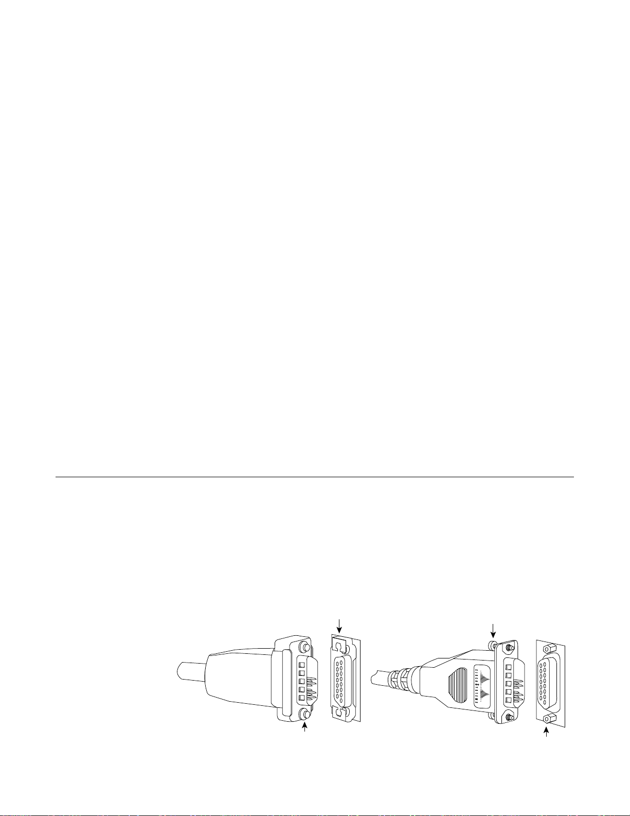
The type of connector lock you use on the EIP ports depends on the type of Ethernet
interfacecables you use. Cables with two short posts on the cable connector need a port
with a slide-type lock—a bracket on the port slides (or snaps) around the posts on the
cable connector to secure it. Cables with knurled thumbscrews (screws you can tighten
with your fingers) on the cable connector need a port with jackscrews (into which you
insert and tighten the thumbscrews). Both types of locks are shown in Figure 1.
Sliding bracket
Thumbscrew
2Jackscrew Installation Instructions (for EIP Ports)
Post
H1887
Jackscrew
Page 3
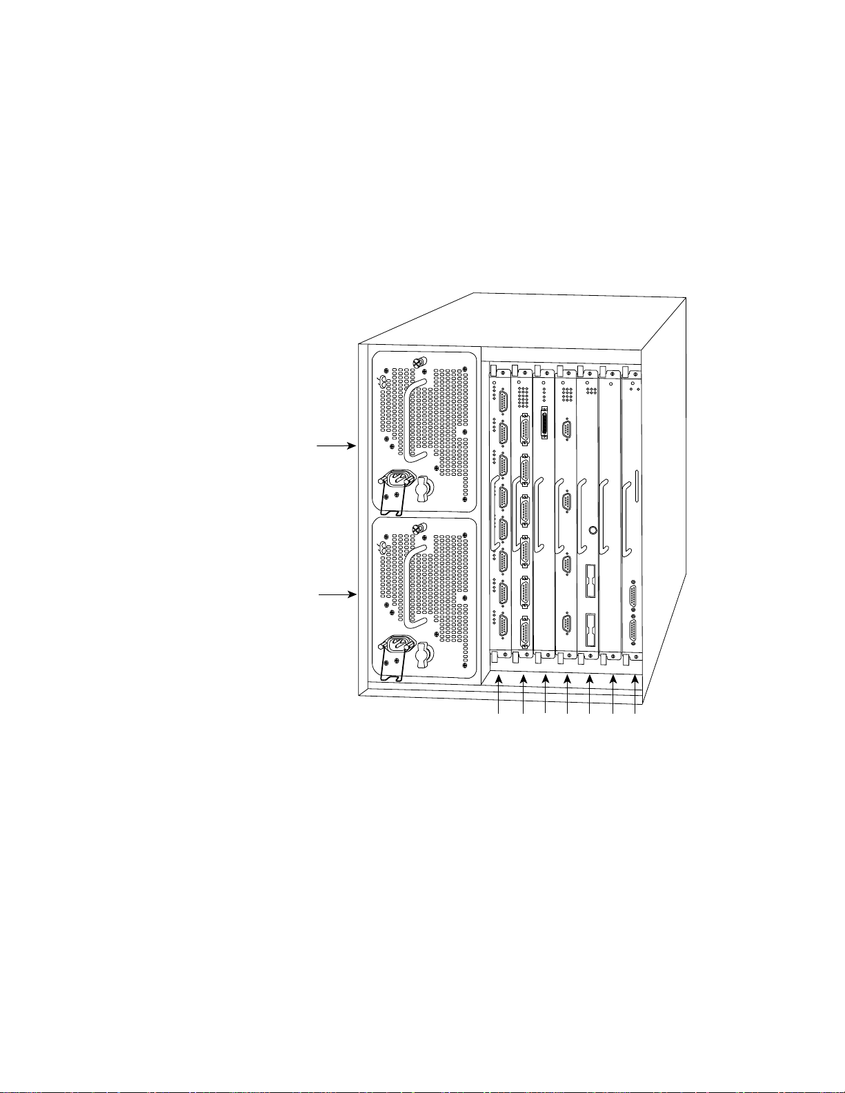
Figure 1 Ethernet Connector Locks, Slide-Type and Jackscrew-Type
TheEIP is the 2, 4, or 6-porthigh-speed Ethernet interface processor for the Cisco 7000
router. The EIP and other interface processors (IPs) slide into slots in the rear of the
router chassis (which is shown in Figure 2) and connect directly to the backplane. You
can replace the connector locks while the EIP is installed in the chassis, provided that
you first shut down the interface ports on which you will change connector locks.
Figure 2 shows a 6-port EIP installed in IP slot 1.
DC FAIL
AC POWER
Upper
power supply
I
O
DC FAIL
AC POWER
H1725
Lower
power supply
I
O
Slot 0
2
1
34SP
slotRPslot
Figure 2 Cisco 7000 Chassis Rear View
Figure 3 shows a 6-port EIP as it is shipped from the factory, with the standard
slide-type locks on all six ports.
The Enabled LED lights to indicate that the EIP is receiving power and is enabled for
operation. The bank of 18 LEDs indicate the state of the individual interfaces, with one
horizontal row of 3 LEDs for each of the 6 ports (numbered 0 through 5). The LEDs
light when the indicated port detects the following network activity:
■ Collision—Lights when a frame collision has been detected.
Jackscrew Installation Instructions (for EIP Ports) 3
Page 4

■ Transmit—Lights when frames are being transmitted. When frames are
transmitted, the Receive LED also lights up because valid traffic is being sent on
the network.
■ Receive—Lights when frames are being received. It indicates that valid traffic is
being received from the network.
ENABLED
0
1
2
3
4
5
COLLISION
TRANSMIT
RECEIVE
ENABLED
Figure 3 Ethernet Interface Processor (EIP)
U101
H1325a
Prerequisites
Before replacing the EIP connector locks, ensure that you have the necessary parts and
tools you will need to perform the installation without interruption.
Required Tools
You need the following tools to perform this replacement procedure.
■ 1/8-inch flat-blade screwdriver to remove the small screws that secure the
slide-lock bracket to the EIP port
■ 3/16-inch nut driver to tighten the jackscrews
■ ESD-prevention equipment or the disposable grounding wrist strap included with
the replacement kit
4Jackscrew Installation Instructions (for EIP Ports)
Page 5
Required Parts
1
The following parts are included in each jackscrew replacement kit. Because the holes
in the EIP are threaded, you need only two lock washers and two jackscrews for each
port. Discard the extra flat washers and hex nuts included in the kit.
■ 2 jackscrews
■ 2 lockwashers
■ 4 flat washers (discard)
■ 2 hex nuts (discard)
Preventing Electrostatic Discharge (ESD) Damage
Electrostatic discharge (ESD) damage, which occurs when electronic cards or
componentsare improperly handled, can result in completeor intermittent failures. The
EIP comprises a printed circuit board that is fixed in a metal carrier. Electromagnetic
interference (EMI) shielding, connectors, and a handle are integral components of the
carrier. Although the metal carrier helps to protect the board from ESD, you can still
damage the board by touching the connector pins. Always use a preventive antistatic
strap whenever working on the EIP, and avoid touching the connector pins.
Following are guidelines for preventing ESD damage:
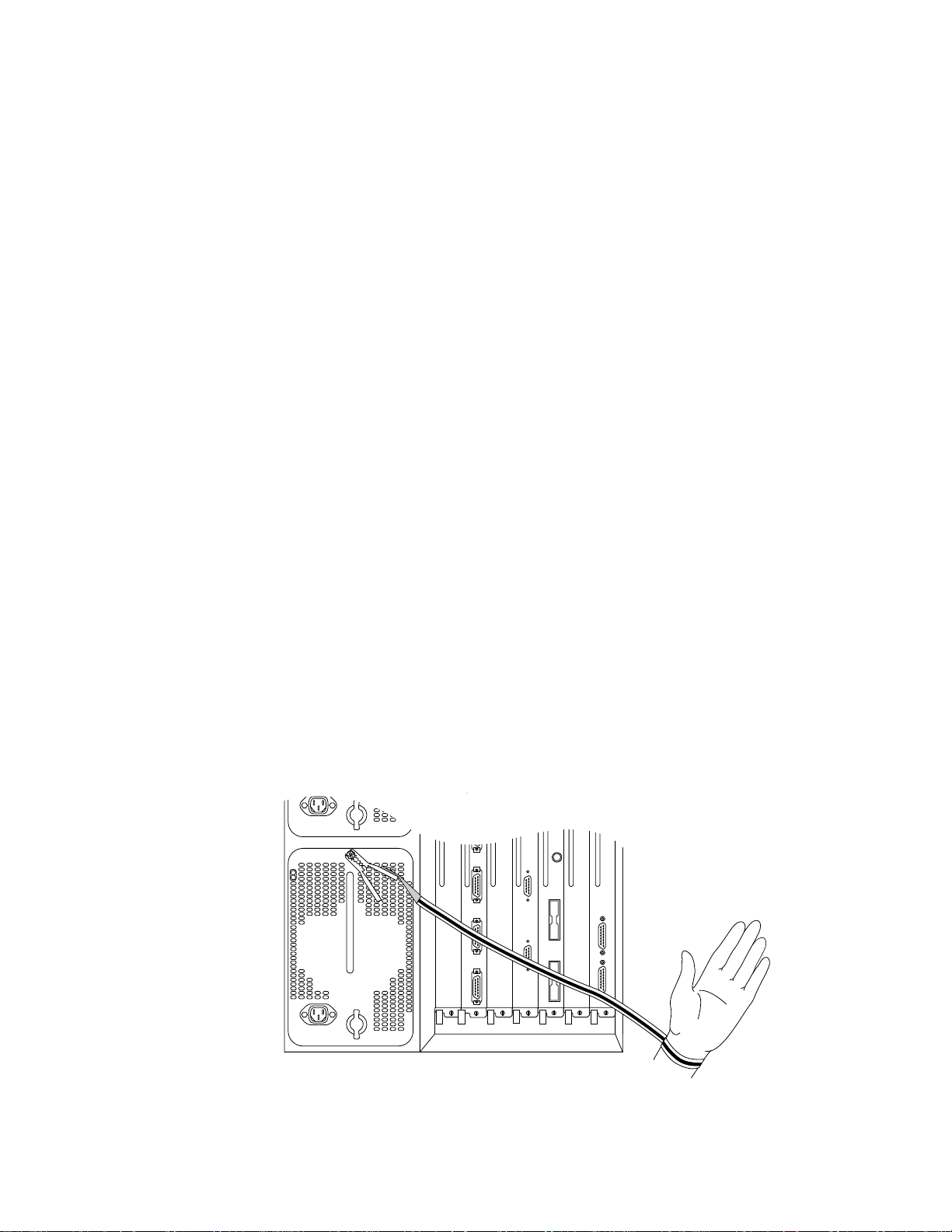
■ Always use an ESD wrist strap or ankle strap and ensure that it makes good skin
contact.
■ Connect the equipment end of the strap to one of the captive installation screws on
an installed power supply (see Figure 4).
■ Handle carriers by the handles and carrier edges only; avoid touching the board or
any connector pins.
■ Avoid contact between the EIP and clothing. The wrist strap only protects the EIP
from ESD voltages on the body; ESD voltages on clothing can still cause damage.
0
I
O
Figure 4 Placement of ESD Wrist Strap
Jackscrew Installation Instructions (for EIP Ports) 5
H1362a
Page 6

Note: For safety, periodically check the resistance value of the antistatic strap. The
measurement should be within the range of 1 and 10 Mohms.
Installation
The following installation process describes the procedure for shutting down the
interfaces on which you will replace connector locks, removing the slide-type lock
bracket, and installing jackscrews to accommodate screw-type cable connectors.
Note: Although shutting down an interface before replacing the lock is not required,
Cisco Systems recommends that you do so as a precaution to protect the electronic
components in the system and to avoid creating problems on your network.
Shutting Down Interfaces
It is unlikely that interface ports will be enabled if you have not been able to connect
the network interface cables. However, if any of the interfaces are already enabled, you
canavoidpotentialproblemsbyadministrativelyshuttingtheinterfacedownand,when
the replacement is complete, enabling the interface again with commands you enter
from the console terminal.
The shutdown interface subcommand disables all functions and prevents all packet
transmission on the interface that you specify with the interface type slot/port
command. The no shutdown interface subcommand turns the interface back on.
Because interface is a privileged-level configuration command, you may need a
password to enable the privileged level of the EXEC command interpreter.
Following is an example session to first enter the privileged level and configuration
mode, and then to specify and shut down each of the first two Ethernet ports (port 0 and
port 1) on an EIP installed in slot 1 of the Cisco 7000. Entering Ctrl-Z saves the
configuration and returns you to the EXEC command interpreter.
Router>enable
Password:secretword
Router#configure
Configuring from terminal, memory, or network [terminal]?
interface ethernet 1/0
shutdown
interface ethernet 1/1
shutdown
^Z
6Jackscrew Installation Instructions (for EIP Ports)
Page 7

After you have replaced the connector locks, reenable the interfaces by entering the
command no shutdown, as shown in the following partial example.
interface ethernet 1/1
no shutdown
^Z
You can display the current state of an individual Ethernet interface by entering the
command show interface type slot/port, or you can omit the interface type and address
to display interface information for all network interfaces in the router.
Followingis a partial, sample session that displays information about the first Ethernet
port (port 0) on an EIP installed in slot 1. Only the first few lines of the display are
included in the example, because the state of the interface (up or down) is indicated on
the first line of the display.
Router>show interface ethernet 1/0
Ethernet1/0 is administratively down, line protocol is down
Hardware is cxBus Ethernet, address is 0000.0c (bia.0c02.d0cc)
(display text deleted)
Router>show int eth 1/1
Ethernet1/1 is up, line protocol is up
Hardware is cxBus Ethernet, address is 0000.0c (bia.0c02.d0ce)
You can also use the show configuration command to display the status of all
interfaces. Refer to the 9.17 Addendum to the Router Products Configuration and
Reference publication for complete command descriptions and instructions.
Removing the Slide Lock
The bracket for slide-type locks is secured to the EIP port with two small screws. You
can complete this replacement procedure without removing the EIP from the chassis.
Follow these steps to remove the slide-type locks from the EIP ports.
Step 1: Ensurethat the ESD-preventionstrap you are wearing is clipped to a captive
Step 2: On the first connector port to be changed, use the 1/8-inch screwdriver to
Step 3: Pull the slide-lock bracket, which is shown in Figure 5, off the connector.
(display text deleted)
installation screw on the power supply or another unpainted area of the
chassis where it makes good contact.
loosen and remove the two small screws that secure the bracket to the
connector port.
.
Figure 5 Connector Slide-Type Lock Bracket
Jackscrew Installation Instructions (for EIP Ports) 7
H1457a
Page 8

Step 4: Repeat steps 2 and 3 for all addition ports that require jackscrews.
Step 5: Place the removed brackets and slotted screws aside; you can discard them
after the jackscrews are installed, and the installation is complete.
Installing the Screw-Type Lock
Use the hardware provided in the replacement kit to reinstall the connector.Do not use
any of the hardware you removed from the slide-type lock bracket.
Step 1: Ensurethattheslide-typelock bracket, showninFigure 5, has been removed
from the connector port.
Step 2: Insert a lock washer onto the shaft of a jackscrew and push it up to the head
of the jackscrew.
EIP
H1458a
Figure 6 Jackscrew and Lock Washer Installation
Step 3: Insertthejackscrewinto one of the threaded holes on the connector.Turn the
jackscrew clockwise about two full turns to thread it into the hole.
Step 4: Repeat steps 2 and 3 for the second jackscrew and lock washer, placing the
second jackscrew in the other threaded hole on the connector. Turn the
jackscrew clockwise about two full turns to thread it into the hole.
Step 5: Observe both jackscrews edge-on and turn them another half turn to ensure
they are threaded properly.
Step 6: Use the 3/16-inch nut driver to tighten the jackscrews in the connector. Do
not overtighten the screws; the lock washer will secure the jackscrews in
place, and the thumbscrews on the cable connector, when inserted and
tightened, will further tighten the jackscrews.
Step 7: Repeat steps 1 through 6 for all addition ports that require jackscrews.
Step 8: Proceed to the next section to check the installation.
8Jackscrew Installation Instructions (for EIP Ports)
Page 9

Checking the Installation
To check the interfaces, you will connect network interface cables to the EIP ports,
reenable any interfaces you shut down, if any, then check the LEDs and console
displays to verify the status of the interfaces.
Step 1: Connect network interface cables to the EIP ports.
Step 2: If any ports are shut down, use the no shutdown interface subcommand to
Step 3: Observe the EIP LEDs (shown in Figure 3) to check the state of the
Step 4: If the system fails to recognize an Ethernet interface, check the cables that
Step 5: If you installed a new cable on an interface port that was previously
Step 6: Use show commands to display the state of the interfaces as follows:
reenable them. Refer to “Shutting Down Interfaces” on page 6 for examples.
interfaces. The LEDs should light to indicate traffic or detected activity on
each port that has been brought up.
are connected to the EIP ports. Ensure that the cables are inserted in the EIP
ports and that the connections are secured with the slide locks or
thumbscrews.
functioning properly, suspect the new cable. Check the cable for the correct
polarity and type; if another cable is available, swap out the cable and
observe the EIP LEDs to see if the interface responds with a different cable.
■ Enter the command show int [type slot/port] to display information
about a specific interface port.
■ Enter the command show interfaces to display information about all
interfaces
■ Enter the command show configuration to check the configured state
(up or administratively down) of all interfaces.
Step 7: If the EIP itself appears to have failed (if the Enabled LED is not lit), use the
show controller cxbus command to display information about all cxbus
interface processors.
Step 8: If an error message is displayed on the terminal, refer to the Cisco 7000
Addendum to Router Products Configuration and Reference publication for
error message definitions.
An error condition exists if any of the previously configured interfaces fail to show any
activity, or of the EIP appears to be malfunctioning. If this happens, refer to the
instructions in “Obtaining Technical Assistance” on page 2 to contact a service
representative or the TAC.
When you have verified that all interfaces are in the state they were in before this
procedure, the installation is complete. You can now resume normal operation. Refer
to the 9.17 Addendum to Router Products Configuration and Reference or the EIP
Installation and Configuration Instructions publications to configure new interfaces.
Jackscrew Installation Instructions (for EIP Ports) 9
Page 10

This document is to be used in conjunction with the Cisco 7000 Hardware Installation and Maintenance publication.
APPI, ciscoBus, Cisco Systems, CiscoWorks, CxBus, Netscape, The Packet, and SMARTnet trademarks, and the Cisco logo is a registered
trademark of Cisco Systems, Inc. All other products or services mentioned in this document are the trademarks, service marks, registered
trademarks, or registered service marks of their respective owners.
Copyright © 1993, Cisco Systems, Inc.
All rights reserved.
 Loading...