

Cisco Systems ISM-BTS-R2, BTS-R3 User Manual

Navini Networks, Inc. Ripwave Base Station I&C Guide
Chapter 3
Chapter 3: Commissioning
This chapter provides post-installation instructions on provisioning, configuring, calibrating,
testing, and commissioning the Ripwave Base Station.
Review Customer Network Plans
As part of preparing to put the BTS into commission, it is important to review the actual installed
site against the customer Network Architecture Plan - i.e., checking that all equipment and
software are installed and available for use. Verify that all routers are installed and IP addresses
are correct. Finally, make sure the installation is approved and signed off by all responsible
parties.
Install EMS Server
The EMS is the management interface for all elements in the Ripwave system. The EMS Server
has to be installed on a computer that is connected directly to the Base Station (called the Test
EMS) or through the system backhaul (customer EMS).
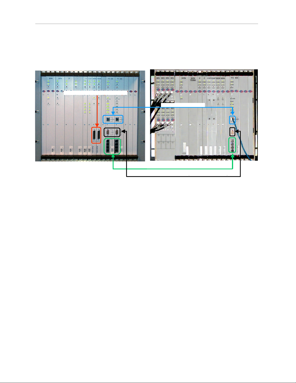
For testing purposes, the Test EMS Server is connected through an Ethernet hub or switch to the
Ethernet port found on the front of the BTS (Figure 48). Note that the EMS Server does not
support more than one Network Interface Card (NIC).
The other port on the front of the CC card is a Serial (Universal Data) Port, also known as the
Console Port. Using a laptop/portable computer connected through the data port, an on-site
technician can communicate directly with the BTS using a terminal emulation software package.
However, this is not recommended. It is always best to rely on the EMS interface for BTS
information.
When connecting the Ripwave equipment to the backhaul, refer to the Regulatory Information in
Chapter 1, Page 8 – specifically regarding cabling to Ethernet or T1 backhauls. Ethernet
connections require a UL497B listed protection device to be installed between the BTS and the
first network device. T1 connections must be routed from the BTS through a UL497 listed
protection device at the demarcation point. The interconnect cables for T1 backhauls must be a
minimum #26 AWG wire, in accordance with NEC/CEC standards.
Part #40-00047-07 Rev F v1.0 (TTA) 75
October 9, 2003
Ripwave Base Station I&C Guide Navini Networks, Inc.
Chapter 3
Figure 48: Ports on CC and MDM Cards
Combo/Split Chassis TTA
Combo/Split Chassis TTA
Serial Ports (factory use only)
Serial Ports (factory use only)Serial Ports (factory use only)
Ethernet Connectors
Ethernet ConnectorsEthernet Connectors
T1 Connectors
T1 Connectors
Serial Port (a.k.a. Console Port)
Serial Port (a.k.a. Console Port)
If the customer’s EMS is installed and can be accessed through the backhaul, it can be connected
via T1 or Ethernet to the BTS and used for testing purposes. The EMS software installation
procedures can be found in the EMS Software Installation Guide, P/N 40-00017-00.
After the EMS Server and Client applications are installed, the EMS database needs to be
configured with the settings that are designated for the Base Station. The settings are found in the
Network Architecture Plan provided by the customer.
Verify Cable Connections
Before proceeding, verify that all power is connected and present. Ensure that all T1 or Ethernet
connections are installed correctly and are active. Verify that the BTS and the RFS are properly
installed and that all cables are connected.
76 Part #40-00047-07 Rev F v1.0 (TTA)
October 9, 2003

Navini Networks, Inc. Ripwave Base Station I&C Guide
Chapter 3
Configure & Power Up the BTS
Overview
During initial power up a minimal set of configuration parameters have to be input to the BTS
through the serial port on the CC card. These early configuration parameters are referred to as
the “boot parameters”. They are required to get the BTS to communicate with the EMS Server so
that all the configuration data can be downloaded from EMS to the BTS.
The PC used at this point is a Test EMS Server (i.e., laptop). If the customer’s actual EMS
Server is available, a separate Test EMS (i.e., laptop) may not be necessary. For simplification,
whether it is a Test EMS laptop or the customer’s EMS Server, we refer to the device at this
stage as the Test EMS.
Set Up the Test EMS
Typical ly, in order to keep a constant link an Ethernet hub (10/100 Base-T) connects the Test
EMS to the BTS via a male to female RS-232 cable connected to the CC serial port. A
connection between the serial port on the CC and the serial port on the Test EMS is also used.
Standard communication software, i.e., a standard terminal emulation program, such as Windows
HyperTerm or TeraTerm, is used during these early configuration stages.
Step 1. Verify all RF cables going to the BTS are securely connected to the proper connector.
Step 2. Connect an Ethernet cable to the Ethernet connector located on the CC card and to an
Ethernet hub. Connect another Ethernet cable from the Ethernet hub to the Ethernet
connector on the PC containing the Test EMS Server and Client applications.
Step 3. Connect an RS-232 cable (DB-9 male to female) to the serial port (UART) located on
the CC card to the serial port connector on the Test EMS computer.
Note: A VT 100 terminal or any standard Windows based ASCII terminal emulation
program can be used for connecting to the serial port. The connection for
HyperTerminal is explained here. The steps to get to the HyperTerminal program may
be different due to variances in the Operating Systems and in the setup of the PC.
Step 4. Power on the Test EMS Server.
Step 5. On the desktop, go to Start > Programs > Accessories > HyperTerminal >
HyperTerminal (using whichever terminal emulation program you are running).
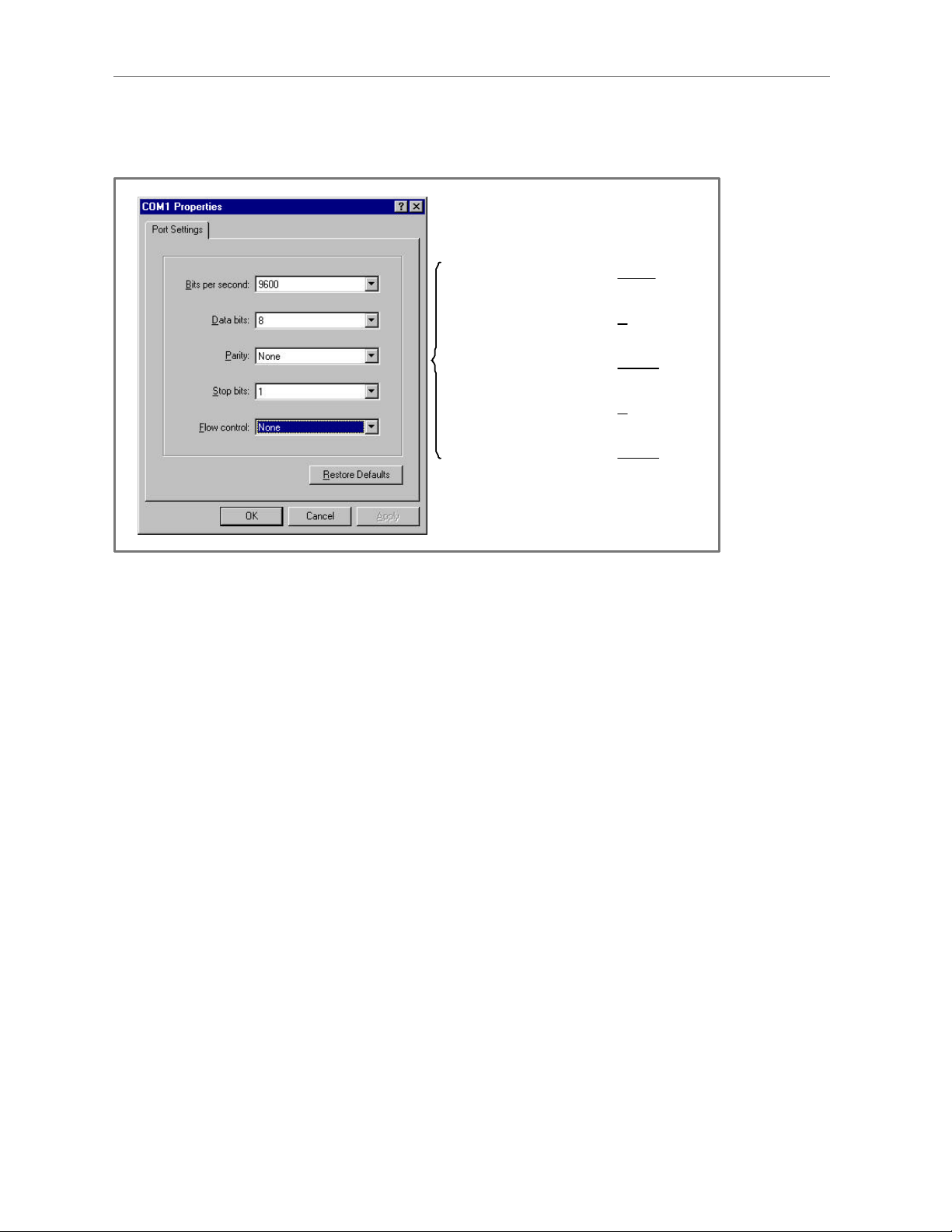
Step 6. In the COM1 Properties window (Figure 49), under the Port Settings tab, enter the
following configuration options. Click OK.
Part #40-00047-07 Rev F v1.0 (TTA) 77
October 9, 2003
Ripwave Base Station I&C Guide Navini Networks, Inc.
Chapter 3
Figure 49: COM1 Properties
Bits per second: 9600
Bits per second: 9600
Data Bits: 8
Data Bits: 8
Parity: None
Parity: None
Stop Bits: 1
Stop Bits: 1
Flow Control: None
Flow Control: None
Step 7. On the Test EMS Server, click on the Server icon to start the EMS Server. NOTE: This
step assumes you have loaded and configured the EMS Server & Client applications.
Step 8. Click on the EMS Configuration & Alarm Manager (CAM) icon to start the EMS
Client GUI.
Step 9. At the EMS Configuration & Alarm Manager login screen, enter the user name and
password. The defaults are both emsAdmin.
Add BTS in EMS
Once you have the CAM application running on the Test EMS server, you will need to click on
the BTS element tab to add the new BTS. Only the minimal configuration parameters have to be
completed at this time - i.e., BTS name, ID, IP address, subnet mask, and gateway. Follow the
Network Architecture Plan designed for this system.
Also configure the GPS offset time. The default is 0 minutes, indicating the BTS would be
located in the same time zone as Greenwich Mean Time (GMT). Change this value to whatever
time is appropriate to the location of the BTS in relation to GMT time zone. For example, if the
BTS is located in Dallas, Texas, which is 6 hours behind GMT time zone, you would enter –360.
As you will see in the section that follows, you will also configure the RFS splitter loss at this
time. For more details about configuring a BTS, refer to the Ripwave Configuration Guide.
78 Part #40-00047-07 Rev F v1.0 (TTA)
October 9, 2003

Navini Networks, Inc. Ripwave Base Station I&C Guide
Chapter 3
Configure RFS (Splitter Loss Value)
Each RFS shipped is pre-programmed for the customer’s specific operating environment. An
RFS Configuration CD accompanies the RFS equipment when it is shipped. The CD includes an
RFS script and a Quick Guide with procedures on selecting the appropriate splitter loss values to
be entered into the EMS database for the given Base Station. Each Configuration disk is unique
to the individual RFS that is shipped. You cannot use the same disk on other RFS equipment.
RFS Configuration Procedure
Step 1. Remove the RFS Configuration disk from the RFS packaging, and insert it in the
floppy drive of the Test EMS.
Step 2. Copy the folder named “RFS” that is on the disk to the Test EMS Server:
<ems install dir>/scripts.
It will take approximately 20 seconds to complete.
Step 3. Open the new folder on the EMS server. You will see a list of file names. The format
of the file names is as follows:
RFS_serial number_frequency.cli
Example: “RFS_024300001_2402500.cli” - This example of the configuration file is
for an RFS with serial number 024300001 and a center frequency of 2.4025.
Verify the correct serial number in the file name against the serial number of the RFS
equipment. The equipment serial number may be found on the back of the RFS panel
or on the side of the bottom cylinder of the omni antenna.
Step 4. Determine which file you need to run, depending on the provisioned frequency of your
BTS.
NOTE: For 2.6 GHz systems, select the frequency that is closest to your provisioned
center frequency. To find the provisioned center frequency for your BTS, open the
EMS Configuration & Alarm Manager (CAM) application. Select the BTS tab and
specific BTS, then Air Interface / Layer 2 / Carrier Data / Show Configuration. This
will display the center frequency information.
Step 5. Open the selected CLI file for editing using any text processing application program.
Note the power splitter values listed there (i.e., write them down or print them out).
Step 6. Modify the line that starts with “bts” by changing the BTS ID for your BTS. The
default is “BTS 1”. For example, if the ID for your BTS is 252, change the “1” to
“252”.
Part #40-00047-07 Rev F v1.0 (TTA) 79
October 9, 2003

Ripwave Base Station I&C Guide Navini Networks, Inc.
Chapter 3
Step 7. Save this file as text, and then close it.
Step 8. Start the EMS Config CLI application to run “script <CLI script>”. Do this by entering
the following:
>enable <user name> <password>
>configure
>script scripts/rfs/rfs_<serial number>_<7-digit frequency>.cli
NOTE: For Unix operating systems, the CLI text is case sensitive and the slash marks
should be backward slashes instead of forward slashes.
Step 9. View the Power Splitter values in EMS to verify that the CLI script ran as expected.
The Power Splitter values may be found under Layer 1 / Show Configuration >
Antenna Table. You will need to “Refresh” the active screen to view the updated
information.
Step 10. Type “Exit” twice to exit the Config CLI edit mode.
Power Up BTS
Now you are ready to power up the BTS.
Step 1. Ensure that input power has been connected to the BTS.
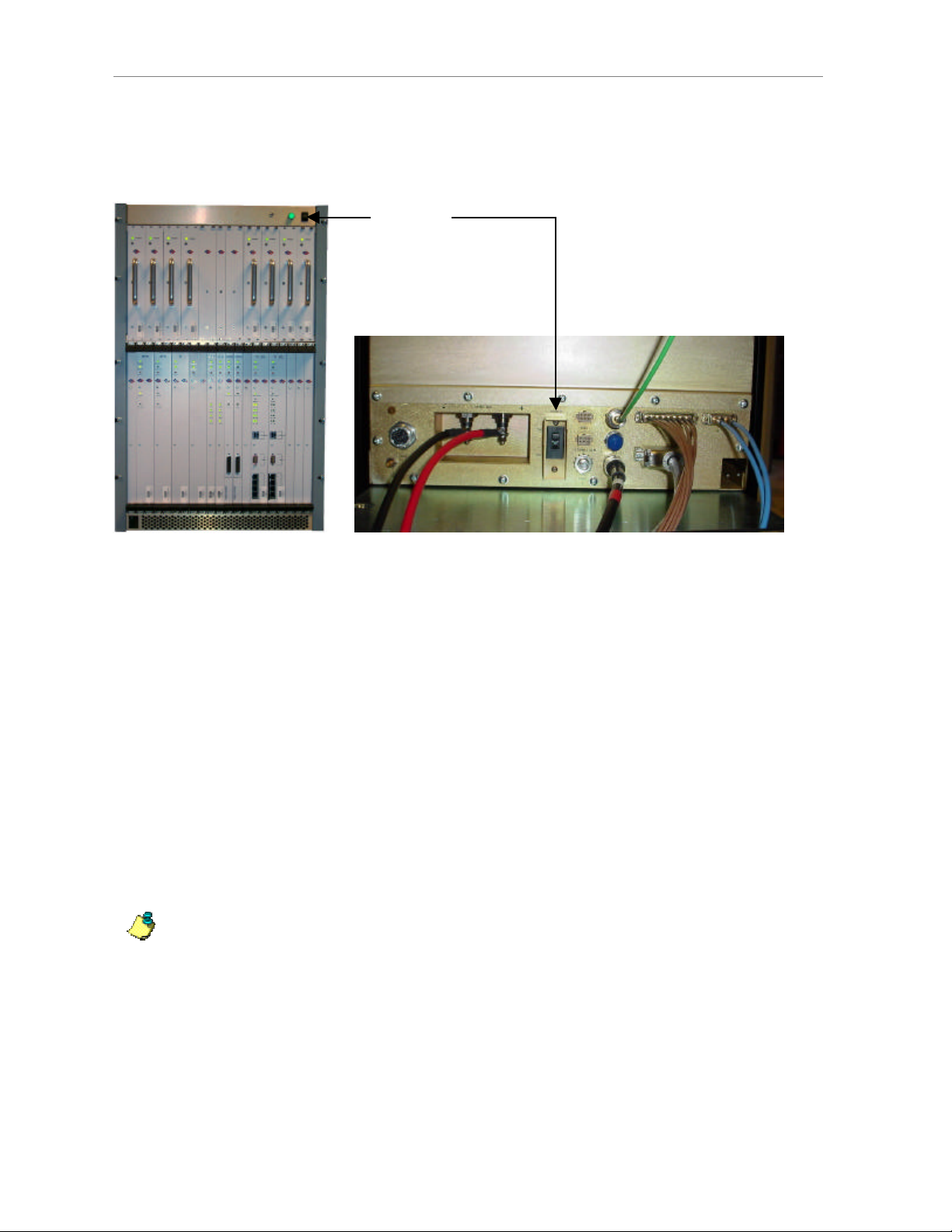
Step 2. Switch the Power to ON. If the BTS is a Combo Chassis, the switch is located on the
top right front of the BTS. The green Power On light next to the switch will illuminate
(Figure 50).
If the BTS is a Split Chassis, the Power ON switch is located on the back lower middle
of the Digital shelf. The green LEDs on the RF/PA modules and the circuit cards in the
BTS chassis should illuminate.
The Power switch for the TTA is located on the lower middle back of the chassis.
80 Part #40-00047-07 Rev F v1.0 (TTA)
October 9, 2003
Navini Networks, Inc. Ripwave Base Station I&C Guide
Chapter 3
Figure 50: BTS Power On Switches
Combo Chassis
Combo Chassis
Power
Power
ON/OFF
ON/OFF
Off/On switch
Off/On switch
Split Chassis
Split Chassis
Step 3. Watch for the auto-boot countdown command. Type in config on the computer
keyboard to interrupt the standard boot sequence. The window of time to type in
“config” after auto-boot starts is 20 seconds.
BTS Bootup
The BTS is shipped with a default value of a 20-second countdown to interrupt the standard
bootup sequence. You can escape the standard bootup when the display shows the following:
autoboot countdown : quick [quick|delayed]
To escape the initialization sequence, type in config before the 20-second counter reaches zero.
Note: Under the next section, “Boot Prompt”, you will see how to disable the 20-second
countdown in lieu of a shorter, 1-second countdown. This will minimize downtime
during unattended restart conditions, for example, if there is a power outage and the BTS
is recovering.
Part #40-00047-07 Rev F v1.0 (TTA) 81
October 9, 2003

Ripwave Base Station I&C Guide Navini Networks, Inc.
Chapter 3
Boot Prompt
After you have escaped from the automated boot sequence, the console will display a
rudimentary Boot prompt:
[Navini Boot]:
This prompt offers the ability to perform a small set of operations. Enter ‘?’ or ‘h’ followed by
the Enter key to display a list of commands (Exhibit 1). To invoke any of the commands, simply
enter the single letter command with optional parameters, followed by the Enter key.
.
Exhibit 1: Boot Commands
[Navini Boot]: ?
? - print this list
@ - resume boot sequence
p - print boot params
c - change boot params
d adrs[,n] - display memory
m adrs - modify memory
f adrs, nbytes, value - fill memory
t adrs, adrs, nbytes - copy memory
@ – Use this command once all parameters have been set as desired. This will resume the boot
initialization sequence that you escaped from previously.
p – This command displays a concise representation of the current parameters used for boot
configuration.
c – Use this command to alter the current boot parameters. Once selected, a detailed sequence of
options is prompted, and is covered in detail later. After all of the items in this list are completed,
you return to the [Navini Boot]: prompt. This option sequence allows you either to accept the
current value by pressing the Enter key or to enter a new value from the range or values listed,
followed by the Enter key. Additionally, you can enter ‘.’ followed by the Enter key to erase the
current value of an item and return it to a default state. If you make an error, you can choose ‘-‘
(hyphen) followed by the Enter key to return to the previous item in the list. Alternatively, you
can fix an error by proceeding with the selections and select ‘change' when you return to the
[Navini Boot]: prompt.
d – Display memory allows you to display portions of the BTSs memory with user-defined
values. It should only be performed with the assistance of a certified Navini service technician.
m – Modify memory allows you to alter portions of the BTSs memory with user defined values.
It should only be performed with the assistance of a certified Navini service technician.
82 Part #40-00047-07 Rev F v1.0 (TTA)
October 9, 2003

Navini Networks, Inc. Ripwave Base Station I&C Guide
Chapter 3
f – Fill memory allows you to alter portions of the BTSs memory with a fixed pattern. It should
only be performed with the assistance of a certified Navini service technician.
t – Fill memory allows you to alter portions of the BTSs memory with a pattern from another
area of memory. It should only be performed with the assistance of a certified Navini service
technician.
Ethernet Configuration
The Ethernet configuration is grouped into three sections: general, EMS, and traffic path. An
example of the Ethernet configuration parameters is shown in Exhibit 2.
Exhibit 2: Ethernet Configuration
[Navini Boot]: p
date and time : 01/09/2003[10:19] MM/dd/yyyy[hh:mm]
autoboot countdown : delayed [quick|delayed]
ems inet : 172.16.0.10
snmp community : public
traffic path : enet [enet|atm]
mac address : 00:04:6a:00:01:20
ip on enet (active) : 172.16.23.181
ip on enet (standby) : 172.16.23.182
netmask on enet : 255.255.0.0
ip on backplane : 10.0.0.1
gateway on enet : 172.16.0.100
General
The general section offers you the ability to change the date and time manually. If a GPS has
been installed, the BTS will automatically set the date and time:
date and time : 08/21/2002[13:21] MM/dd/yyyy[hh:mm]
When this line is displayed, the current date (08/21/2002) and time [13:21] are displayed. Accept
the defaults by pressing the Enter key, or enter “date” at the console and a new value using the
format indicated in military time (Hours 1-24). All 5 fields must be entered as specified. Leading
zeroes can be omitted.
Previously, it was mentioned that the 20-second auto-boot countdown timer can be disabled and
a 1 second countdown can be used instead. To enable this feature, change the autoboot
countdown item from “delayed” (which is 20 seconds) to “quick”, which is 1 second:
autoboot countdown : delayed [quick|delayed]
Part #40-00047-07 Rev F v1.0 (TTA) 83
October 9, 2003

Ripwave Base Station I&C Guide Navini Networks, Inc.
Chapter 3
EMS
This section concerns the configuration of the EMS Server itself. First, the Internet (inet) IP
address of the Server is specified. Make sure to fill this field with the address of the Server used
to configure this BTS. Your BTS is shipped with this field un-initialized. You must provide a
valid 4-digit IP address before you can proceed. For example:
ems inet : 172.16.0.10
The second parameter that you must specify to allow the EMS Server to recognize this BTS is a
community string for the EMSs Simple Network Management Protocol (SNMP) interface. The
default community string shipped with the BTS is “public”. Press the Enter key to accept this
default, or type in a new value and press the Enter key to alter it:
snmp community : public
Traffic Path
The last major block of configurations required for an Ethernet backhaul to the BTS is the traffic
path parameters. The first prompt instructs the BTS to use the Ethernet as the WAN (backhaul)
configuration. It must be set to “enet” for an Ethernet backhaul.
If “atm” is selected, proceed with the description in the ATM or IMA sections. The BTS is preconfigured to use Ethernet for the WAN connection. Press the Enter key to accept this default:
traffic path : enet [enet|atm]
The BTS address is specified next. Every BTS must be uniquely addressed and have values that
equate in the EMS configurations. This address information defines the Layer 2 parameters first,
and then it defines the Layer 3 parameters. For Layer 2, you are only given an opportunity to see
the Ethernet Media Access Control (MAC) address used by this BTS. This is a unique number
programmed in the BTS. You cannot alter it. However, situations may develop in which you
need to know the MAC address and, therefore, need to display the information. For example:
mac address : 00:04:6a:00:01:20
Next are the IP addresses that represent this BTS: one for the active CC card and one for the
standby CC card. Enter the IP for the active controller card, for 172.16.23.181, and the next IP
(172.16.23.182) is automatically assigned to the Standby card.
ip on enet (active) : 172.16.23.181
ip on enet (standby) : 172.16.23.182
84 Part #40-00047-07 Rev F v1.0 (TTA)
October 9, 2003

Navini Networks, Inc. Ripwave Base Station I&C Guide
Chapter 3
The standby field is only displayed for your convenience and cannot be altered. Note that the
BTS automatically handles switching the address when a failure occurs on an active Controller
card, requiring the standby Controller to go into service. However, the MAC addresses remain
fixed.
Coupled with any IP configuration is a need to specify the corresponding subnet mask. Refer to
common network administration literature for guides on addresses, networks, masks, and
gateways. In short, the subnet mask identifies the portion of the IP address that is common to
those devices connected to the same Ethernet. The most important “other” device is the BTSs
default gateway (specified later).
The portion is identified using a logical “and” of the mask with the address. For example, a
subnet mask of 255.255.0.0 and with an IP address of 172.16.23.182 yields a network of
172.16.x.x. In this case, the default gateway must also be on the 172.16.x.x network. The BTS
requires that this association be met. If not, you will be asked to try again.
netmask on enet : 255.255.0.0
The BTS uses a high-speed Serial Line Internet Protocol (SLIP) connection to communicate with
the redundant T1/Controller Card. This interface is only used internally and has a fixed subnet
mask of 255.255.255.252.
The host portion of the address –that is, the least significant 2 bits– is automatically provided by
the software based upon slot ID. However, you may want to alter the default network address to
avoid conflict with your network.
The BTS is shipped with the 10.0.0.0 network as the internal network. This is a reserved network
not used on the Internet. However, if your private network utilizes this private address space, you
may need to change it to avoid the conflict.
ip on backplane : 10.0.0.1
As for the default gateway for the BTS, all traffic routed outside the directly connected Ethernet
port goes through the gateway. Furthermore, the gateway must be reachable on the directly
connected Ethernet port. Therefore, the BTS will prevent you from entering a default gateway
address that fails the logical “and” test discussed previously. This address is specified on the line
item shown below:
gateway on enet : 172.16.0.100
Part #40-00047-07 Rev F v1.0 (TTA) 85
October 9, 2003
 Loading...