

Page 1
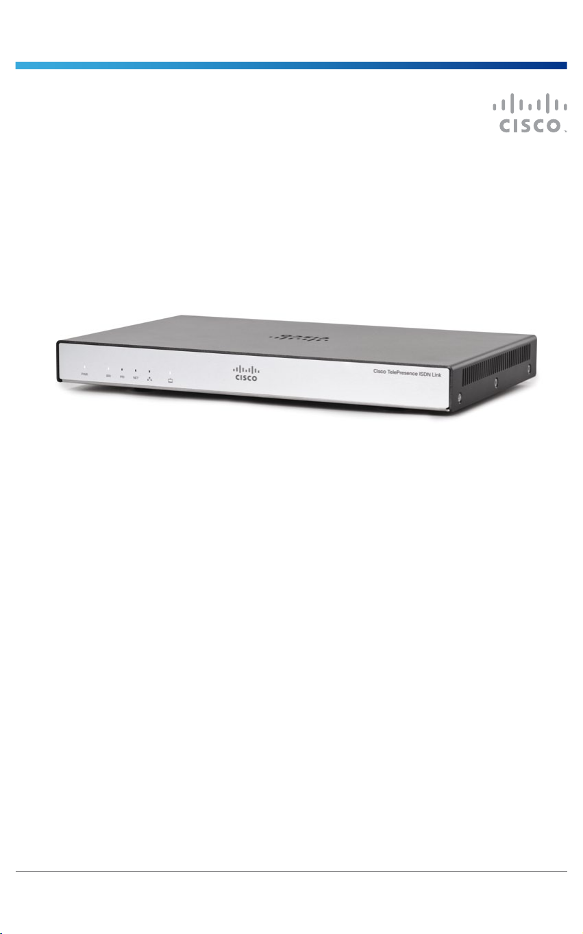
Cisco TelePresence ISDN Link
Installation guide
Package contents:
• ISDN Link
• Power Adapter
• LAN Cable
• Foot bumpers
• Installation Guide
78-20749-02 | JANUARY 2013.
Copyright © 2013 Cisco Systems, Inc. All rights reserved.
Page 2
Cisco TelePresence ISDN Link
Installation guide
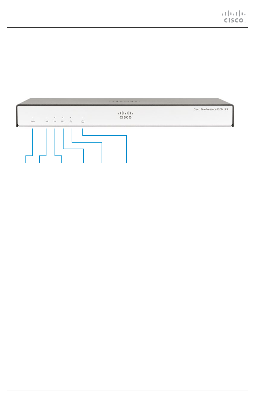
Front panel
The LED indicators are located on the front panel of the unit.
Power BRI PRI NET LAN Endpoint
Power The LED lights up and remains lit when the ISDN Link is powered up.
When the ISDN Link is not congured correctly this LED will be red. This will
typically happen when you power up the unit for the rst time.
The LED typically turns red when there is an error with the selected interface
(BRI/PRI/NET), or possibly other system errors that require attendance. Check
the ISDN Link status information for errors:
• When used in automatic pairing mode the ISDN Link status information is
available from the TelePresence system’s web interface.
• When used in manual pairing mode, see the user documentation for further
details.
BRI/PRI/NET The BRI/PRI/NET LED indicates the activated network interface type. The LED
blinks while there is call activity on the selected interface type.
LAN The LED ickers when there is activity on the LAN network.
Endpoint The LED ickers when there is activity between the ISDN Link and the
endpoint (codec / video system).
78-20749-02 JANUARY 2013 Page 2 of 16 Copyright © 2013 Cisco Systems, Inc. All rights reserved.
Page 3
Cisco TelePresence ISDN Link
Installation guide
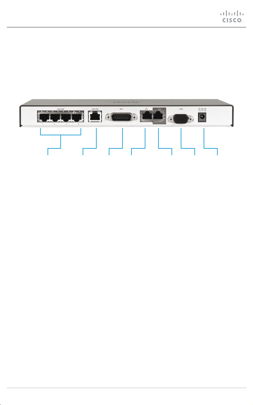
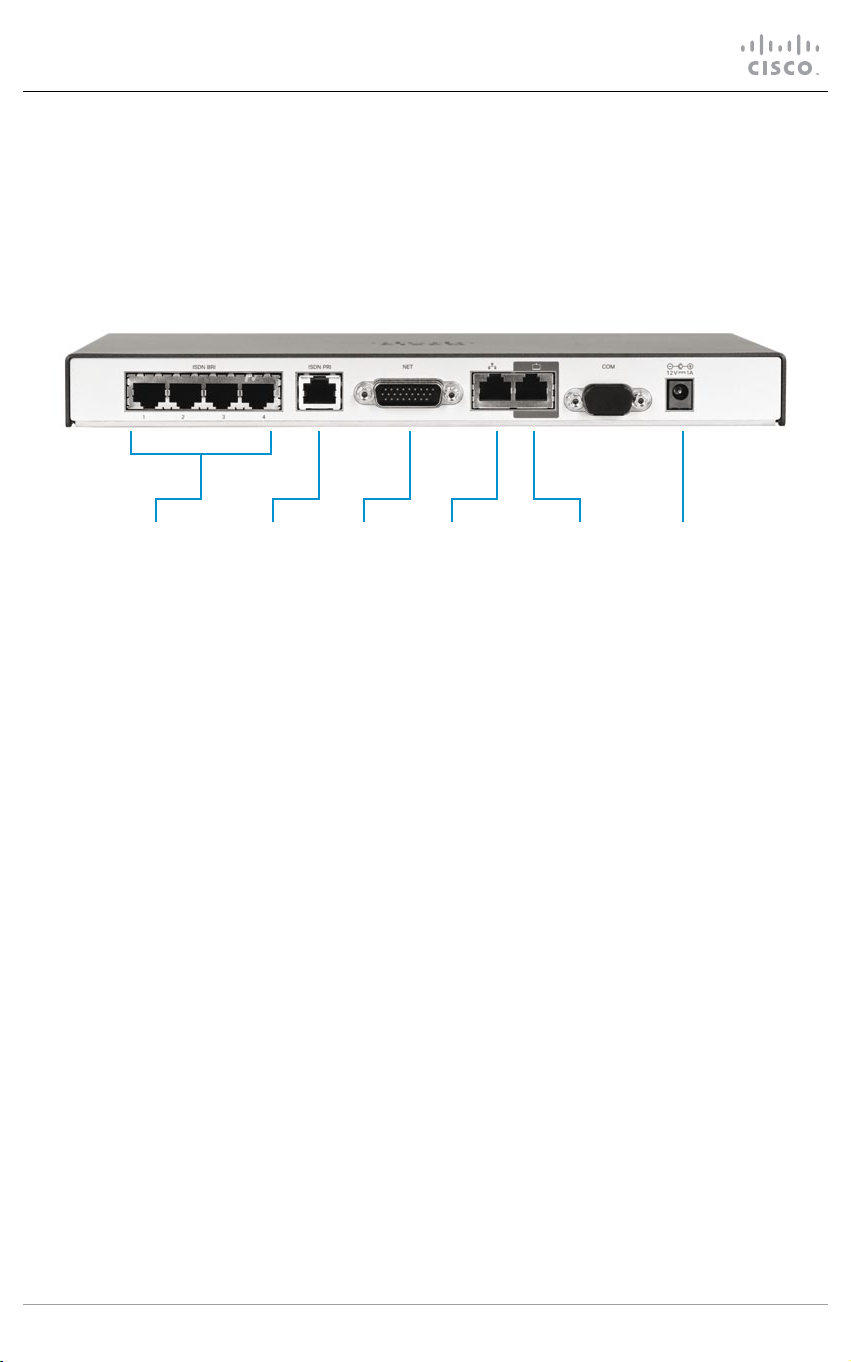
Rear panel
The connectors are located on the rear panel.
ISDN BRI ISDN PRI NET LAN Endpoint COM Power
1-4
Select one of the three options
• ISDN BRI S/T (RJ45) 512 kbps (4 × 128 kbps)
• ISDN PRI (RJ45) 1920 kbps (E1) / 1472 kbps (T1)
• NET (External Network, V.35/RS449/RS366/RS530) 1920 kbps
LAN (Ethernet 10/100/1000 Mbps, RJ45)
Connect to the IP network.
Endpoint (Ethernet 10/100/1000 Mbps, RJ45)
Connect to the endpoint (codec / video system).
COM/Serial port (RS-232)
Connect to a PC/laptop for conguration. Use: 115200 bps, 8 data bits, 1 stop bit, no parity.
Power
External power adapter with 12 V/1.25 A DC output supports 100/240 VAC and 50/60 Hz
inputs.
78-20749-02 JANUARY 2013 Page 3 of 16 Copyright © 2013 Cisco Systems, Inc. All rights reserved.
Page 4
Cisco TelePresence ISDN Link
Installation guide
Installation
Connect the cables as described in step 1 to 4.
1A 2 3 41B 1C
1. Select one of the three options for the
ISDN line connection:
A. Connect the ISDN cable(s) between
the ISDN BRI port(s) and the ISDN
line(s),
B. or, connect the ISDN cable between
the ISDN PRI port and the ISDN line,
C. or, connect the V.35 cable between
the NET port and the external
network line.
2. For system conguration, connect a
Category 5e Ethernet cable between the
Ethernet port on the ISDN Link and the
LAN network.
3. Connect a Category 5e Ethernet cable
between the Endpoint port on the
ISDN Link and the Ethernet port on the
endpoint.
4. Connect the supplied power adapter
between the power connector and an
electrical outlet.
CAUTION: Always use the AC-DC adapter
shipped with the product.
78-20749-02 JANUARY 2013 Page 4 of 16 Copyright © 2013 Cisco Systems, Inc. All rights reserved.
Page 5
Cisco TelePresence ISDN Link
Installation guide
Automatic pairing mode
Pairing is a process in which the ISDN Link and endpoint communicate with each other in
order to establish a connection. The ISDN Link is shipped with pairing mode set to Auto,
which enables the ISDN Link to be discovered by an endpoint. When pairing is completed the
ISDN Link is dedicated to the endpoint it has been paired with. The automatic pairing mode
provides an improved user experience, but requires that the endpoint supports this feature.
Supported versions
Automatic pairing mode is supported in software version IL1.1, and later, for Cisco
TelePresence MX-, SX-, EX-, and C-Series running TC6.0, and later. If using software earlier
than TC6/IL1.1 see the About manual pairing mode section.
NOTE: The endpoint and ISDN Link must be on the same subnet. The Ethernet cable should
be directly connected between the Endpoint port, on the ISDN Link, and the Ethernet 1 port,
on the endpoint.
Start pairing
1. Open a web browser, enter the address of the endpoint, and login.
2. From the top menu, go to Conguration > Peripherals.
3. Click the Manage ISDN Link button. This will open the ISDN Link page.
4. Click the Search for devices button.
5. Choose your ISDN Link from the list and Click the Pair! button.
During the pairing process a message will display: Pairing with device: <MAC address>.
The ISDN Link is identied by the MAC Address, which is found on a label
underneath the unit.
6. When sucessfully paired the following text will appear on the ISDN Link page:
This TelePresence device is paired with an ISDN Link.
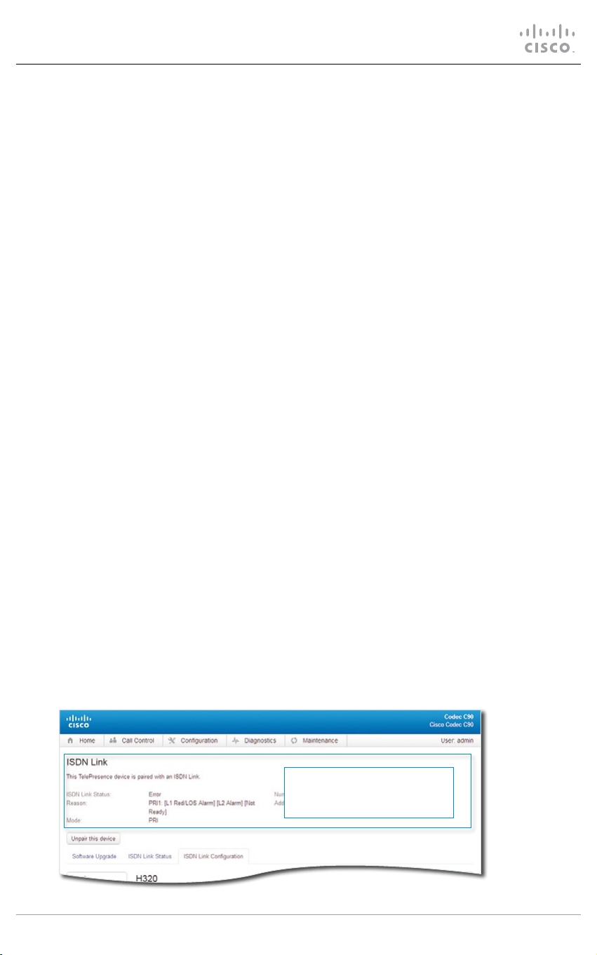
Checking the status of the ISDN Link
Navigate to Conguration > Peripherals > Manage ISDN Link > ISDN Link Conguration.
After having congured the
ISDN Link, check this area to
see the status of the pairing.
78-20749-02 JANUARY 2013 Page 5 of 16 Copyright © 2013 Cisco Systems, Inc. All rights reserved.
Page 6

Cisco TelePresence ISDN Link
Installation guide
Conguring the ISDN Link
Navigate to Conguration > Peripherals > Manage ISDN Link > ISDN Link Conguration.
Click ISDN Link
Conguration
to open the
conguration
menu.
78-20749-02 JANUARY 2013 Page 6 of 16 Copyright © 2013 Cisco Systems, Inc. All rights reserved.
Page 7

Cisco TelePresence ISDN Link
Installation guide
Conguration example with PRI E1 mode
First choose from the list of menus to the left, then congure the parameters.
Navigate to H320 > General
Settings > NetType.
In this example the H320 Net
Type is:
• PRI
Click the Save button.
Navigate to ISDN > PRI >
SwitchType.
In this example the ISDN PRI
Switch Type is:
• Euro
Click the Save button.
Navigate to ISDN > PRI >
Interface 1.
Enter the number of high and
maximum channels for the
PRI Euro switch:
• HighChannel: 31
• MaxChannels: 30
Enter your ISDN PRI number:
• NumberRangeStart: xxx
• NumberRangeStop: xxx
Click the Save buttons.
Go to Conguration > Peripherals and check the ISDN status information to conrm there are no
errors before proceeding. If any errors, or if the power LED is red, please check your conguration.
78-20749-02 JANUARY 2013 Page 7 of 16 Copyright © 2013 Cisco Systems, Inc. All rights reserved.
Page 8

Cisco TelePresence ISDN Link
Installation guide
A few more conguration examples for the ISDN Link
You can skip this page if you already have congured the ISDN Link.
On this page you can see a few more conguration examples for the ISDN Link. The ISDN
Link is congured from the TelePresence system’s web interface. Navigate to Conguration
> Peripherals > Manage ISDN Link > ISDN Link Conguration. See the previous pages for
guideance on how to access the menus.
The examples on this page are from the web interface of the TelePresence endpoint.
Example with PRI T1 mode
H320 > General Settings > NetType: PRI (Set the net type)
ISDN > PRI > SwitchType: NI (Set the PRI switch type)
ISDN > PRI Interface 1 > MaxChannels: 23 (Set the number of PRI channels)
ISDN > PRI Interface 1 > HighChannel: 23 (Set the number of the high PRI channel)
ISDN > PRI Interface 1 > NumberRangeStart: xxx (Enter your PRI number)
ISDN > PRI Interface 1 > NumberRangeStop: xxx (Enter your PRI number)
Example with BRI Euro type
H320 > General Settings > NetType: BRI (Set the net type)
ISDN > BRI > SwitchType: Euro (Set the BRI switch type)
ISDN > BRI Interface [1 to 4] > Mode: On (Enable the BRI interfaces in use)
ISDN > BRI Interface [1 to 4] > DirectoryNumber Number [1 and 2]: xxx (Enter the BRI numbers
according to assigned numbers for each interface in use.)
Example with External Network
H320 > General Settings > NetType: External (Set the net type)
ExternalNetwork > Interface 1 > CallControl: RS366 (Set call control protocol)
ExternalNetwork > Interface 1 > Clocking: Dual (Set clocking mode)
ExternalNetwork > Interface 1 > DtrPulse: On (If using RS530, set DTRPulse to On; else set to O).
See the ISDN Link Administrator Guide for further details. Go to: http://www.cisco.com/go/
isdnlink-docs and navigate to the Maintain and Operate > Maintain and Operate Guides section.
78-20749-02 JANUARY 2013 Page 8 of 16 Copyright © 2013 Cisco Systems, Inc. All rights reserved.
Page 9

Cisco TelePresence ISDN Link
Installation guide
Conguring the endpoint for ISDN (H320)
When paired to ISDN Link, the default call setttings for the TelePresence endpoint can be
congured for ISDN (H320), or you can set the call protocol and call rate each time you make
a call.
Conguring the default call settings to ISDN (H320)
1. Open a web browser and log in to the TelePresence endpoint.
2. Navigate to Conguration > System conguration > Conference 1 > DefaultCall and set
the Protocol to H320, and click the Save button.
Conguring the call settings to ISDN (H320) by each call
• If using a Touch device, see the section: Making a call using the Touch controller.
• If using a remote control, see the section: Making a call using the remote control.
78-20749-02 JANUARY 2013 Page 9 of 16 Copyright © 2013 Cisco Systems, Inc. All rights reserved.
Page 10

Cisco TelePresence ISDN Link
Installation guide
Making a call using the Touch controller
Touch the panel gently to wake
up the system.
1. Tap DialPad or Contacts and
enter the ISDN number you
want to call.
If your the default call
protocol is set to ISDN
(H320), proceed to Step 6,
else proceed to Step 2.
Navigate to Call settings:
1
2. Tap the right arrow button to
open the call dialog.
3. Tap Call settings button to
open the ISDN call settings.
4. In the Call settings menu,
move the call protocol slider
and choose ISDN.
5. In the Call settings menu,
move the bandwidth slider to
set the appropriate call rate.
If dialing a telephone number,
use the slider to choose
Audio Only.
6. Tap the green Call button to
make the call.
2
3
4
5
Connecting the call may take
up to 30 seconds.
78-20749-02 JANUARY 2013 Page 10 of 16 Copyright © 2013 Cisco Systems, Inc. All rights reserved.
6
Page 11

Cisco TelePresence ISDN Link
Installation guide
Making a call using the remote control
Press any button on the remote control
to wake up the system.
1. Press
the Home menu.
2. Press
Call menu.
3. Use the numeric pad and enter the
ISDN number you want to call.
If your the default call protocol is
set to ISDN (H320), proceed to
Step 6, else proceed to Step 4.
(home) button to open
(right arrow) to open the
4
5
1
(home)
(ok)
(ok)
2
(right arrow)
3
4. Press the fth soft button to display the
Call Type menu. Use the arrow keys to
navigate and choose ISDN. Press
to conrm your selection.
5. Press the fourth soft button to display the
Call Rate menu. Use the arrow keys to
navigate and choose the call rate.
If dialing a telephone number, choose
Audio Only. Press
selection.
(ok) to conrm your
(ok)
6. Press
Tap the green Call button to make
the call.
Connecting the call may take up
to 30 seconds. A message will
show on screen while the call is
connecting.
78-20749-02 JANUARY 2013 Page 11 of 16 Copyright © 2013 Cisco Systems, Inc. All rights reserved.
(call) to connect the call.
6
(call)
Page 12

Cisco TelePresence ISDN Link
Installation guide
About manual pairing mode
You can skip this page if using the ISDN Link in automatic pairing mode.
Manual pairing mode of the ISDN Link is managed from a command line interface. Connect to
the ISDN Link through the serial port (COM) or through SSH over the network.
Supported versions
Manual pairing mode is supported from software version IL1.0, and later, for TelePresence
EX-, MX-. SX-, and C-Series running TC5. If you have TC6/IL1.1 please use automatic pairing
mode as described in the Automatic pairing mode section.
Manual pairing of the ISDN Link
See the ISDN Link API Reference Guide (IL1.1) for further details on manual pairing mode.
Go to: http://www.cisco.com/go/isdnlink-docs and navigate to the Reference Guides >
Command References section.
78-20749-02 JANUARY 2013 Page 12 of 16 Copyright © 2013 Cisco Systems, Inc. All rights reserved.
Page 13

Cisco TelePresence ISDN Link
Installation guide
Wall mounting
If you want to mount the ISDN Link on a wall, follow the instructions below. The unit must be
mounted with the front panel facing up.
It is of great importance that the wall mount unit is safely installed, that the wall is able to
support the product and that the screws or mounting means used are suitable for the wall
and the weight of the product.
This type of equipment is to be installed by the submittor’s/dealer’s qualied installer. Installer
is responsible for obtaining safety inspection of the structural integrity of the installation by the
local authority/inspection department.
Front panel
180 mm / 7.1 in
facing up.
110 mm / 4.3 in
Bottom view of the unit.
Connectors
facing down.
Table stand
Mount the the four foot bumpers on its feets if you would like to place the ISDN Link on a
table.
78-20749-02 JANUARY 2013 Page 13 of 16 Copyright © 2013 Cisco Systems, Inc. All rights reserved.
Page 14

Cisco TelePresence ISDN Link
Installation guide
Where to nd additional support and information
for your Cisco TelePresence product
ISDN Link documentation
For more information about conguring and using your Cisco TelePresence
ISDN Link, see the user documentation that is available on our web site:
http://www.cisco.com/go/isdnlink-docs
Safety Information
Before connecting the power supply, read the Regulatory Compliance and Safety
Information (RCSI) document that is available on our web site:
http://www.cisco.com/en/US/docs/telepresence/endpoint/isdn-link/
compliance_safety_guide/isdn-link_compliance_and_safety_guide.pdf
Support
For support, go to: http://www.cisco.com/support
78-20749-02 JANUARY 2013 Page 14 of 16 Copyright © 2013 Cisco Systems, Inc. All rights reserved.
Page 15

Cisco TelePresence ISDN Link
China RoHS Hazardous Substance Table
Installation guide
Note This Table is a regulatory document required for products shipped to the People’s
Republic of China.
EMC Class A declaration for China
Applies to the systems that complies with the EMC Directive Standard EN 55022, Class A.
声明
此为A级产品,在生活环境中,该产品可能会造成无线电干扰。在这种 情况下,
可能需要用户对其干扰采取切实可行的措施。
WARNING:
This is a class A product. In a domestic environment this product may cause radio
interference in which case the user may be required to take adequate measures.
78-20749-02 JANUARY 2013 Page 15 of 16 Copyright © 2013 Cisco Systems, Inc. All rights reserved.
Page 16

Cisco TelePresence ISDN Link
Installation guide
On our web site you can nd an overview of the worldwide Cisco contacts.
Go to: http://www.cisco.com/web/siteassets/contacts
Corporate Headquarters
Cisco Systems, Inc.
170 West Tasman Dr.
San Jose, CA 95134 USA
Cisco, Cisco Systems, the Cisco logo, and the Cisco Systems logo are registred trademarks or trademarks
of Cisco Systems, Inc. and/or its aliates in the Unites States and certain other countries. All other
trademarks mentioned in this document or web site are the property of their respective owners. The use of
the word partner does not imply a partnership relationship between Cisco and any other company. (0705R)
78-20749-02 JANUARY 2013 Page 16 of 16 Copyright © 2013 Cisco Systems, Inc. All rights reserved.
 Loading...