

Page 1

CHA PT ER
2
Product Overview
This chapter provides an overview of the features available for the Cisco IR800 Integrated Services
Routers (ISRs) and contains the following sections:
• General Description, page 2-3
• Hardware Overview, page 2-4
–
IR829 Product Overview, page 2-4
–
IR809 Product Overview, page 2-8
–
Reset Button, page 2-11
• Software Overview, page 2-13
• Hardware Differences Between IR809, IR829, and the C819HG, page 2-14
• Antenna Recommendations, page 2-16
• Features Supported in Different IOS Releases, page 2-16
• Related Documentation, page 2-17
General Description
The 800 Series Industrial Integrated Services Routers are compact, ruggedized, Cisco IOS Software
routers. They offer support for integrated 4G LTE wireless WAN (both 809 and 829 models) and wireless
LAN capabilities (829 model only). The IR829 offers an Internal WLAN Access Point which runs
on-board the router. The AP803 runs its own IOS software independently from the IR829 IOS, and
requires configuring. The AP803 works as a standalone access point or with a wireless controller.
They offer:
• Easily and rapidly deployable
• Highly available, highly secure, and reliable
• Designed for machine-to-machine (M2M) communication and for mobile vehicle communication in
harsh environmental conditions
• Designed to withstand hostile environments, tolerating a wide temperature range
These industrialized routers deliver enterprise-class features, including highly secure data, voice, and
video communications to stationary and mobile network nodes across wired and wireless links. They can
deliver enterprise-grade, wireline-like functionality.
Cisco IR800 Integrated Services Router Software Configuration Guide
2-3
Page 2
Chapter 2 Product Overview
The routers also support Cisco IOx Software, providing an open, extensible environment for hosting
additional operating systems and applications directly at the network edge. They can enhance other
Cisco IoT System products across multiple industries, including transportation, manufacturing,
electrical utilities, and others.
For a complete listing of the routers capabilities, see the Cisco 829 Industrial Integrated Services Routers
Product Information.
Hardware Overview
This section covers the overview of the IR809 and IR829.
IR829 Product Overview
Figure 2-1 shows the IR829.
Figure 2-1 Cisco IR829 Integrated Services Router
Hardware Overview
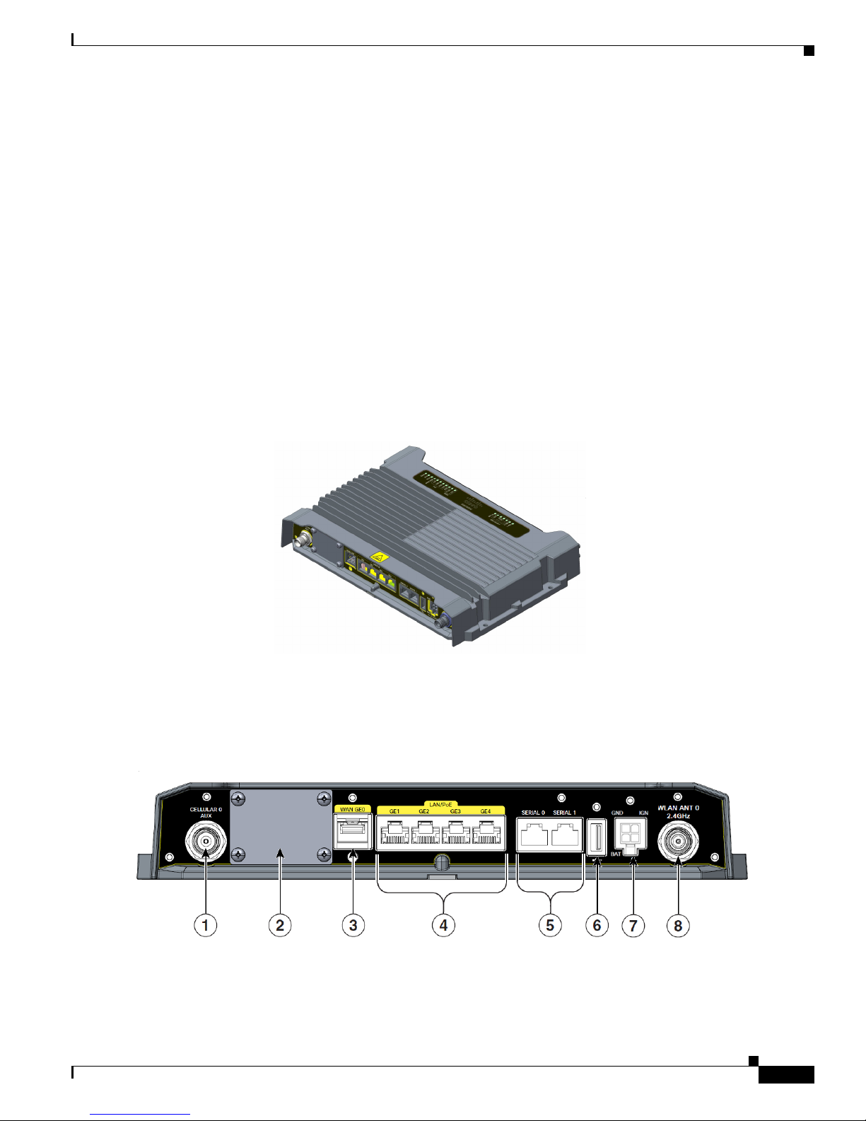
Figure 2-2 shows the front panel details of the Cisco IR829 Single Modem.
Figure 2-2 Cisco IR829 Front Panel Single Modem
Cisco IR800 Integrated Services Router Software Configuration Guide
2-4
Page 3
Chapter 2 Product Overview
1 CELLULAR 0 AUX 5 Serial Ports
2 Limited Modularity Slot 6 USB-A Port
3 Gigabit WAN (SFP) 7 Power Input, Battery, and Ignition connector.
4 Gigabit Ethernet LAN/PoE (RJ45) 8 WLAN ANT 0 2.4GHz
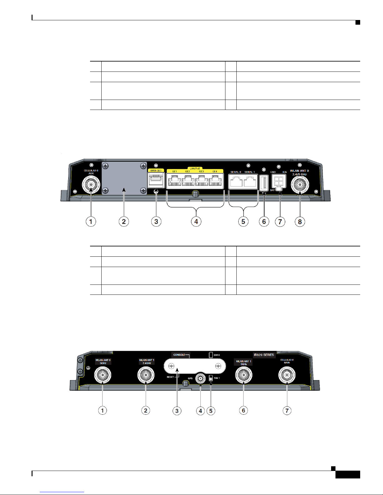
Figure 2-3 shows the front panel details of the Cisco IR829 Dual Modem.
Figure 2-3 Cisco IR829 Front Panel Duel Modem
Hardware Overview
Refer to the DC Power section for pin-outs.
1 CELLULAR 0 AUX 5 Serial Ports
2 Limited Modularity Slot 6 USB-A Port
3 Gigabit WAN (SFP) 7 Power Input, Battery, and Ignition connector.
Refer to the DC Power section for pin-outs.
4 Gigabit Ethernet LAN/PoE (RJ45) 8 WLAN ANT 0 2.4/5GHz
Figure 2-4 shows the back panels details of the Cisco IR829 Single Modem.
Figure 2-4 Cisco IR829 Back Panel Single Modem
Cisco IR800 Integrated Services Router Software Configuration Guide
2-5
Page 4
Chapter 2 Product Overview
1 WLAN ANT 0 5GHz 5 Denotes SIM card order, SIM0 on top and
2 WLAN ANT 1 2.4GHz 6 WLAN ANT 1 5GHz
3 Cover over SIM cards, reset button and
4 GPS SMA
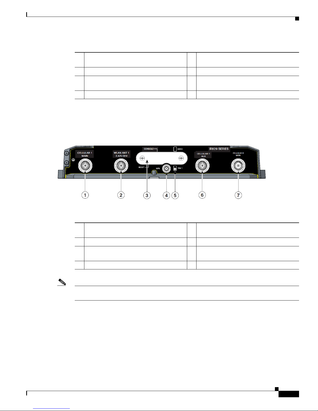
Figure 2-5 shows the back panels details of the Cisco IR829 Dual Modem.
Figure 2-5 Cisco IR829 Back Panel Dual Modem
Hardware Overview
SIM1 on bottom.
7 CELLULAR 0 MAIN
console port cover, see Figure 2-6
1 Cellular 1 Main 5 Denotes SIM card order, SIM0 on top and
SIM1 on bottom.
2 WLAN ANT 1 2.4/5GHz 6 Cellular 1 AUX
3 Cover over SIM cards, reset button and
7 CELLULAR 0 MAIN
console port cover, see Figure 2-6
4 GPS SMA
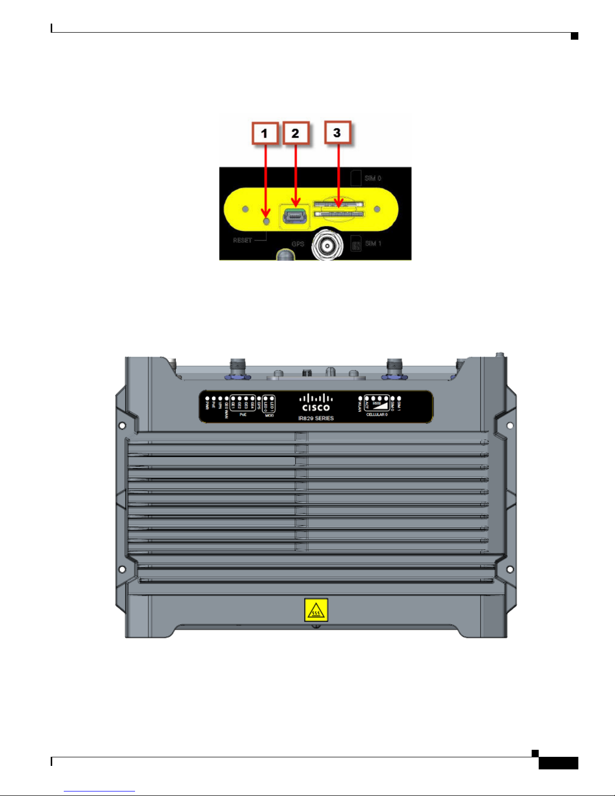
Note Behind the SIM Door Assembly, there is a reset switch (1), Mini USB console port (2), and Dual SIM
slots (3). See Figure 2-6 for details
Cisco IR800 Integrated Services Router Software Configuration Guide
2-6
Page 5
Chapter 2 Product Overview
Figure 2-6 Behind the SIM Door
Figure 2-7 shows the top of the Cisco IR829.
Figure 2-7 Cisco IR829 Top Cover
Hardware Overview
Figure 2-8 shows the LED detail from the Dual Modem SKU. Single Modem SKUs will only have
Cellular0 LEDs.
Cisco IR800 Integrated Services Router Software Configuration Guide
2-7
Page 6

Chapter 2 Product Overview
Figure 2-8 Cisco IR829 LED Detail
IR809 Product Overview
Figure 2-1 shows the IR809.
Figure 2-9 Cisco IR809 Integrated Services Router
Hardware Overview
Figure 2-2 shows the front panel details of the Cisco IR809.
Cisco IR800 Integrated Services Router Software Configuration Guide
2-8
Page 7

Chapter 2 Product Overview
Figure 2-10 Cisco IR809 Front Panel
Hardware Overview
1 S0 RS232 DCE/RS485 Combo Port 8 Grounding Point
2 S1 RS232 DTE only 9 Mini type-B USB console/debug port
3 GE0 (10/100/1000) 10 SYS LED
4 GE1 (10/100/1000) 11 Alarm LED
5 USB 2.0 (Type-A Host Port) 12 WAN/WWAN LEDs
6 RESET Button 13 SIM Card LEDs
7 DC Power/Alarm Connector
Note LEDs are viewable from the top and from the front of the IR809.
Figure 2-4 shows the back panels details of the Cisco IR809.
Cisco IR800 Integrated Services Router Software Configuration Guide
2-9
Page 8

Chapter 2 Product Overview
Figure 2-11 Cisco IR809 Back Panel
Hardware Overview
1 DIV TNC connector for 4G Modem
2 SMA connector for GPS
3 SIM0 and SIM1 Card Slots
4 MAIN TNC connector for 4G Modem
Figure 2-12 shows the back panels details of the Cisco IR809.
Cisco IR800 Integrated Services Router Software Configuration Guide
2-10
Page 9

Chapter 2 Product Overview
Figure 2-12 Cisco IR809 Top Cover
Hardware Overview
Note See the respective Hardware Installation Guides for detailed description of the LEDs.
Reset Button
Note On the IR829, the rear cover must be removed to expose the reset switch.
The reset button resets the router configuration to the default configuration set by the factory. To restore
the router configuration to the default configuration set by the factory, use a standard size #1 paper clip
with wire gauge 0.033 inch or smaller and simultaneously press the reset button while applying power
to the router.
Starting with release 15.6(1)T, the IR809 and IR829 have changed the way the reset button works. The
IR800 series platforms now perform in the same manner as the C819. The high level description of the
functionality works like this:
• Press and hold the reset button while powering up the router
• During warm reboot this button has no impact on performance
• Simply pressing the button at any time does not reset the router
• The router will not react to the reset button if it is pressed after power-up because the button needs
to be pushed before turning ON/inserting power – to make sure that the condition is detected.
• The push-button cannot be used to boot a IOS image from network. The golden image has to be on
flash: only
Cisco IR800 Integrated Services Router Software Configuration Guide
2-11
Page 10

Chapter 2 Product Overview
Note For the location of the reset button see the appropriate IR809 or IR829 Hardware Installation Guide.
Perform the following steps to use this feature:
Step 1 Unplug power.
Step 2 Press the reset button on the router.
Step 3 Power up the system while holding down the reset button.
The system LED blinks four times indicating that the router has accepted the button push.
Tip The IR800 series of routers do not support password recovery. If needed, use the above procedure to
bring the router to its initial configuration, or to a previously set backup configuration.
Hardware Overview
Booting a Default IOS Image and Default Configuration
The IR800 differs from traditional IOS routers when booting a default IOS image and a default
configuration. These steps apply on a device running 15.6(1)T or later.
Method 1:
Step 1 Save a copy of your IR800 IOS image with the .default extension on flash. For example:
ios-image.default.
Step 2 Save a copy of your IR800 Hypervisor image with the .default extension on bootstrap. For example:
hypervisor-image.default.
Step 3 Save your desired default configuration file with the .cfg extension on flash. For example: config.cfg.
Step 4 Reset your IR800 router by powering it down, then press and hold the RESET button while powering up
the device.
The IR800 router will automatically boot hypervisor-image.default, then ios-image.default, and load the
config.cfg.
Step 5 Make sure there exists only one IOS image with a .default extension, only one configuration file with
the .cfg extension on the flash, and only one hypervisor image with the .default extension on bootstrap.
If you do not have a config.cfg on flash, it will boot with the Cisco default configuration (aka: empty)
startup-config.
Method 2:
Step 1 Check the “boot system” setting configuration in the default configuration file (prior to saving it to
startup-config), and verify that it points to an existing IOS image on the flash: partition.
Cisco IR800 Integrated Services Router Software Configuration Guide
2-12
Page 11

Chapter 2 Product Overview
Note If that particular IOS image is not present, the device will drop in rommon-2 mode and you will
Step 2 Copy your desired default config file to the startup-config.
Step 3 Reload the router. Do NOT enter Yes if prompted whether you want to save the running-config to
startup-config.
Note To simplify the boot process, the IR800 routers do not support the ROMMON configuration register and
the associated CLI commands. The IR800 either boots the pre-configured images, or stops at the
ROMMON prompt for user intervention. In the event of a boot failure, see Chapter 3, “IR800 Bootstrap
Sequence and Troubleshooting” for additional information.
An example of the log activity after a reboot follows:
IR800# show log
*Nov 30 19:31:04.925: %LINEPROTO-5-UPDOWN: Line protocol on Interface GigabitEthernet0,
changed state to down
*Nov 30 19:31:10.651: %PLATFORM-5-RESET_BUTTON: Reset Button pressed during boot up.
*Nov 30 19:31:11.527: %LINK-3-UPDOWN: Interface Async0, changed state to up
*Nov 30 19:31:11.595: %SYS-5-RESTART: System restarted -Cisco IOS Software, ir800 Software (ir800-UNIVERSALK9-M), Version 15.6(1)T, RELEASE
SOFTWARE (fc1)
Software Overview
need to manually boot an IOS image from there.
Software Overview
The IR800 series offers a rich IOS feature set. This section provides a brief overview of these features.
Note Features may be dependent of platform and releases
Feature Description
Cellular Connectivity
Wi-Fi (829 only)
Cisco IOx Application Support Provides an open, extensible environment for hosting OS and applications at the
• 4G LTE, 3.7G, 3.5G, or 3G Cellular WAN link
• External, dual 4G antennas with main and receive diversity for maximum signal
strength connectivity
• Dual subscriber identity module (SIM) capability
• Dual radio 802.11n concurrent 2.4 GHz and 5.0 GHz with embedded 2X3 MIMO
• Up to 300 Mbps data rate per radio
network edge; expansion module slot to enable additional future communication
technologies.
Cisco IR800 Integrated Services Router Software Configuration Guide
2-13
Page 12

Chapter 2 Product Overview
Hardware Differences Between IR809, IR829, and the C819HG
Feature Description
Security Advanced security features that support:
• Access control
• Data confidentiality and data privacy
• Threat detection and mitigation
• Device and platform integrity
Cisco IOT Field Network
Director
Available as the optional Cisco Industrial Operations Kit. This is a software platform
that manages a multiservice network and security infrastructure for IoT applications
such as transportation, smart grid, services, distribution automation and substation
automation.
Cisco IOS Mobile IP Features
• Mobile IP offers transparent roaming for mobile networks, establishing a
transparent Internet connection regardless of location or movement. This enables
mission-critical applications to stay connected even when roaming between
networks.
• Assigned IP addresses to the home network are maintained in private or public
networks.
Cisco IOS Mobile Network
Features
QoS Features
Allows an entire subnet or mobile network to maintain connectivity to the home
network while roaming.
• Provides traffic precedence to delay-sensitive or prioritized applications.
• Facilitates low-latency routing of delay-sensitive industrial applications.
Management and
Manageability
• Network managers can remotely manage and monitor networks with SNMP,
Telnet, or HTTP/HTTPS/SSH, and locally through a console port.
• Support for extensive 3G and 4G LTE-based MIBs allows for centralized
management of remote devices and gives network managers visibility into and
control over the network configuration at the remote site.
• Network managers can reset to a predesignated golden image, as well as
configure an 829 through Cisco IOS Software or through an external reset button.
• Network managers can upgrade 3G, 3.5G, 3.7G, and 4G LTE firmware and router
configurations remotely.
The tight integration with Cisco IOS Software enables router to self-monitor the LTE
WAN link and automatically recover from a radio link failure.
Cisco IOS Software
Requirement
• Cisco IOS Software feature set: Universal Cisco IOS Software
• Cisco IOS Software Release - 15.5(3)M, or later, and modem firmware - 5.5.58,
or later
Hardware Differences Between IR809, IR829, and the C819HG
The IR809 is a very compact cellular (3G and 4G/LTE) industrial routers for remote deployment in
various industries. They enable reliable and secure cellular connectivity for remote asset monitoring and
machine-to-machine (M2M) solutions such as distribution automation, pipeline monitoring, and
roadside infrastructure monitoring.
Cisco IR800 Integrated Services Router Software Configuration Guide
2-14
Page 13

Chapter 2 Product Overview
Hardware Differences Between IR809, IR829, and the C819HG
The IR829 is a highly ruggedized compact cellular (3G and 4G LTE with GPS and dual SIM) and WLAN
(2.4/5GHz) industrial routers supporting for scalable, reliable, and secure management of fleet vehicles
and mass transit applications.
The 819HG-LTE-MNA-K9: Multimode Cisco LTE 2.0 for carriers that operate LTE 700 MHz (band 17),
1900 MHz (band 2 PCS), 850 MHz (band 5), 700 MHz (band 13), 1900 MHz (band 25 extended PCS)
networks; or 1700/2100 MHz (band 4 AWS) networks; backward-compatible with UMTS and HSPA+:
850 MHz (band 5), 900 MHz (band 8), 1900 MHz (band 2 PCS), and 1700/2100 MHz (band 4 AWS),
with EVDO Rev A/CDMA 1x BC0, BC1, BC10.
Hardware Comparison
Feature IR809 IR829 C819HG
OIR of SIM Yes Yes Yes
Guest OS Support Yes Yes Yes
2G/3G/4G Support Yes, dual SIM support, SKUs available per region
See the Chapter 4, “Cellular Interface”for additional
information.
USB Flash Yes Yes No
USB type A Interface Yes Yes No
Console Port Mini USB Mini USB RJ-45
Alarm Port One Alarm input on IR809 No No
IEEE 802.11a/b/g/n WiFi No Yes, depending on the
platform type.
Power Requirements Nominal voltage: 12-48V
DC
Min/max voltage: 9.6 –
60V DC input
Max, Min current: 3A,
0.5A
Nominal voltage: 12V, 24V
DC
Min/max voltage: 9-32V
DC input
Max/Min current: 7.8 A,
2.8 A
819(H)G-4G supports dual-SIM
Different SKU’s per region.
SW MC 7750,7700,7710
No
Nominal voltage: 12V, 24V DC
Min/max voltage: 10-36V DC
Maximum power consumption:
26W
Ethernet Ports 2 x RJ45 10/100/1000Mbs 4 x RJ45 10/100/1000Mbs
Serial Ports 2 x RJ45 (1xRS-232 and 1xRS232/RS-485 12 in 1 Smart Serial
Antenna: Main, Diversity
Yes Yes 819(H)G-4G has Active GPS
and GPS
Maximum power
consumption: 40 W (no
PoE) and 70W (PoE)
4 x RJ45 10/100 Mbs
1 x SFP 1000Mbs
1 x GE 10/100/1000Mbs
SMA Connector and option for 2
4G antennas
Cisco IR800 Integrated Services Router Software Configuration Guide
2-15
Page 14

Chapter 2 Product Overview
Antenna Recommendations
Neither the IR809 or IR829 are shipped with antennas. They must be ordered separately. The IR829
must be installed with 2 antennas (Main & Aux) to guarantee the best performance level. Using a single
antenna may impact the downlink performance by a minimum 3dB, and can be much greater (10-20dB)
due to multipath fading (destructive interference between direct and reflected radio waves).
In case of 3G UMTS, a solo antenna would not be able to switch to the diversity port.
With the IR829, it must be guaranteed >15dB isolation between the WiFi and LTE antennas at all
frequencies of 4G LTE and WiFi operation, for minimum impact to performance. This is ideally
20-25dB.
The Sierra Wireless MC73xx modem series supports MIMO on LTE. WCDMA UMTS HSPA
DC-HSPA+ is diversity only, without MIMO.
Note Poorly installed MIMO antennas, such that the two (or more in case of 3x3, 4x4 MIMO) antennas have
a strong correlation coefficient. This may cause the two streams to interfere with each other (otherwise
known as lack of diversity), since the system has trouble separating the two. The multi-element antennas
(5-in-1, 3-in-1, 2-in-1) have good diversity
Antenna Recommendations
For detailed information about Cisco Antennas, please refer to the following guides:
Cisco Industrial Routers Antenna Guide:
http://www.cisco.com/c/en/us/td/docs/routers/connectedgrid/antennas/installing-combined/industrial-r
outers-antenna-guide.html
Connected Grid Antennas Installation Guide:
http://www.cisco.com/c/en/us/td/docs/routers/connectedgrid/antennas/installing/cg_antenna_install_gu
ide.html
Cisco Aironet Antennas and Accessories Reference Guide
http://www.cisco.com/c/en/us/products/collateral/wireless/aironet-antennas-accessories/product_data_
sheet09186a008008883b.html
Features Supported in Different IOS Releases
The IR800 series was originally released with IOS software version 15.5(3)M. The following lists the
software releases with the features added.
15.5(3)M (initial release)
• Software based Crypto
15.5(3)Mx
• Hardware based Crypto
15.6(1)T
• IR809 Input alarm port, including SNMP Trap support
• SLIP & PPP serial encapsulation on serial interfaces
• Reset button behavior changed to match other 800 series
Cisco IR800 Integrated Services Router Software Configuration Guide
2-16
Page 15

Chapter 2 Product Overview
• IOX phase 2 CAF, 64 bits Linux, IR800-IOXVM image
• Guest OS Serial port access
15.6(2)T
• Ignition power management on the IR829
• Performance improvements on IR800s
15.6(3)M
• Boot time reduction
• Copper SFP support on the IR829
• Serial Baud Rate configuration support
• USB EHCI emulation to GOS Support
• Memory allocation optimization between VDS, IOS and GOS
15.6(3)M0a
• Support added for the Sierra Wireless MC7430 series modems on the IR829.
Related Documentation
15.6(3)M1
• 4G LTE IPv6 Support
• Accelerometer and Gyroscope Support
• IOXVM Storage Partition Enhancement
• IOXVM Graceful Shutdown
• Sierra Wireless MC7430 modem support on the IR809.
15.6(3)M2
• 100Mbs SFP Support on the IR829
• Bridge Virtual Interface Support for IR800 Guest-OS
• New Features for LTE Modems
–
Assisted-GPS support on IR800 MC73xx modems
–
Multi-PDN support on IR800 MC73xx and MC74xx modems
–
2000B MTU support on cellular interface for MC73xx modems
Related Documentation
The following documentation is available:
• Cross-Platform Release Notes for Cisco IOS Release 15.6M&T:
http://www.cisco.com/c/en/us/td/docs/ios/15_6m_and_t/release/notes/15_6m_and_t.html
• All of the Cisco IR800 Industrial Integrated Services Router documentation can be found here:
http://www.cisco.com/c/en/us/support/routers/800-series-industrial-routers/tsd-products-support-s
eries-home.html
Cisco IR800 Integrated Services Router Software Configuration Guide
2-17
 Loading...